EP2503443A2 - Touch screen and method for providing stable touches - Google Patents
Touch screen and method for providing stable touches Download PDFInfo
- Publication number
- EP2503443A2 EP2503443A2 EP12160824A EP12160824A EP2503443A2 EP 2503443 A2 EP2503443 A2 EP 2503443A2 EP 12160824 A EP12160824 A EP 12160824A EP 12160824 A EP12160824 A EP 12160824A EP 2503443 A2 EP2503443 A2 EP 2503443A2
- Authority
- EP
- European Patent Office
- Prior art keywords
- touch screen
- touch
- region
- button
- user
- Prior art date
- Legal status (The legal status is an assumption and is not a legal conclusion. Google has not performed a legal analysis and makes no representation as to the accuracy of the status listed.)
- Withdrawn
Links
Images


Classifications
-
- G—PHYSICS
- G06—COMPUTING; CALCULATING OR COUNTING
- G06F—ELECTRIC DIGITAL DATA PROCESSING
- G06F3/00—Input arrangements for transferring data to be processed into a form capable of being handled by the computer; Output arrangements for transferring data from processing unit to output unit, e.g. interface arrangements
- G06F3/01—Input arrangements or combined input and output arrangements for interaction between user and computer
- G06F3/048—Interaction techniques based on graphical user interfaces [GUI]
- G06F3/0487—Interaction techniques based on graphical user interfaces [GUI] using specific features provided by the input device, e.g. functions controlled by the rotation of a mouse with dual sensing arrangements, or of the nature of the input device, e.g. tap gestures based on pressure sensed by a digitiser
- G06F3/0488—Interaction techniques based on graphical user interfaces [GUI] using specific features provided by the input device, e.g. functions controlled by the rotation of a mouse with dual sensing arrangements, or of the nature of the input device, e.g. tap gestures based on pressure sensed by a digitiser using a touch-screen or digitiser, e.g. input of commands through traced gestures
- G06F3/04886—Interaction techniques based on graphical user interfaces [GUI] using specific features provided by the input device, e.g. functions controlled by the rotation of a mouse with dual sensing arrangements, or of the nature of the input device, e.g. tap gestures based on pressure sensed by a digitiser using a touch-screen or digitiser, e.g. input of commands through traced gestures by partitioning the display area of the touch-screen or the surface of the digitising tablet into independently controllable areas, e.g. virtual keyboards or menus
-
- G—PHYSICS
- G06—COMPUTING; CALCULATING OR COUNTING
- G06F—ELECTRIC DIGITAL DATA PROCESSING
- G06F3/00—Input arrangements for transferring data to be processed into a form capable of being handled by the computer; Output arrangements for transferring data from processing unit to output unit, e.g. interface arrangements
- G06F3/01—Input arrangements or combined input and output arrangements for interaction between user and computer
- G06F3/011—Arrangements for interaction with the human body, e.g. for user immersion in virtual reality
- G06F3/013—Eye tracking input arrangements
-
- G—PHYSICS
- G06—COMPUTING; CALCULATING OR COUNTING
- G06F—ELECTRIC DIGITAL DATA PROCESSING
- G06F3/00—Input arrangements for transferring data to be processed into a form capable of being handled by the computer; Output arrangements for transferring data from processing unit to output unit, e.g. interface arrangements
- G06F3/01—Input arrangements or combined input and output arrangements for interaction between user and computer
- G06F3/03—Arrangements for converting the position or the displacement of a member into a coded form
- G06F3/041—Digitisers, e.g. for touch screens or touch pads, characterised by the transducing means
- G06F3/0416—Control or interface arrangements specially adapted for digitisers
- G06F3/0418—Control or interface arrangements specially adapted for digitisers for error correction or compensation, e.g. based on parallax, calibration or alignment
-
- G—PHYSICS
- G06—COMPUTING; CALCULATING OR COUNTING
- G06F—ELECTRIC DIGITAL DATA PROCESSING
- G06F3/00—Input arrangements for transferring data to be processed into a form capable of being handled by the computer; Output arrangements for transferring data from processing unit to output unit, e.g. interface arrangements
- G06F3/01—Input arrangements or combined input and output arrangements for interaction between user and computer
- G06F3/048—Interaction techniques based on graphical user interfaces [GUI]
- G06F3/0481—Interaction techniques based on graphical user interfaces [GUI] based on specific properties of the displayed interaction object or a metaphor-based environment, e.g. interaction with desktop elements like windows or icons, or assisted by a cursor's changing behaviour or appearance
- G06F3/04812—Interaction techniques based on cursor appearance or behaviour, e.g. being affected by the presence of displayed objects
-
- B—PERFORMING OPERATIONS; TRANSPORTING
- B32—LAYERED PRODUCTS
- B32B—LAYERED PRODUCTS, i.e. PRODUCTS BUILT-UP OF STRATA OF FLAT OR NON-FLAT, e.g. CELLULAR OR HONEYCOMB, FORM
- B32B2457/00—Electrical equipment
- B32B2457/20—Displays, e.g. liquid crystal displays, plasma displays
- B32B2457/208—Touch screens
-
- G—PHYSICS
- G06—COMPUTING; CALCULATING OR COUNTING
- G06F—ELECTRIC DIGITAL DATA PROCESSING
- G06F2203/00—Indexing scheme relating to G06F3/00 - G06F3/048
- G06F2203/048—Indexing scheme relating to G06F3/048
- G06F2203/04808—Several contacts: gestures triggering a specific function, e.g. scrolling, zooming, right-click, when the user establishes several contacts with the surface simultaneously; e.g. using several fingers or a combination of fingers and pen
Definitions
- the exemplary embodiments described herein generally relate to touch screens and more particularly to a method for providing stable touches to a touch screen.
- a touch panel offers intuitive input for a computer or other data processing devices, but may be affected by movement of the touch panel and/or the pilot caused by, for example, turbulence, aircraft vibration, and/or G forces.
- a system and method are provided for a touch screen whose input is less subject to the movement turbulence, G forces, and/or equipment vibrations.
- a method of selecting one of a plurality of buttons displayed on a touch screen includes preventing at least one button on a first portion of the touch screen from registering a touch; sensing a portion of a hand on the first portion; and sensing a touch on another of the plurality of buttons on a second portion of the touch screen.
- a method of selecting one of a plurality of buttons displayed on a touch screen includes preventing a first portion of the touch screen from registering a touch, and sensing a touch to one of the plurality of buttons within a second portion of the touch screen.
- a touch screen includes a display screen; first circuitry configured to display at least one character through the display screen on each of a plurality of buttons; second circuitry configured to sense touches applied to each of the plurality of buttons; and a processor configured to define a region in which a touch to at least a portion of an underlying button will be ignored.
- FIG. 1 is a block diagram of an aircraft system including a touch screen display
- FIGS. 2-4 are frontal views of a touch screen in accordance with a first exemplary embodiment
- FIGS. 5-6 are frontal views of a touch screen in accordance with a second exemplary embodiment
- FIGS. 7-8 are frontal views of a touch screen in accordance with a third exemplary embodiment.
- FIG. 9 is a frontal view of a touch screen in accordance with a fourth exemplary embodiment.
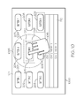
- FIG. 10 is a frontal view of a touch screen in accordance with a fifth exemplary embodiment
- FIGS. 11-12 are frontal views of a touch screen in accordance with a sixth exemplary embodiment
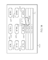
- FIGS. 13-14 are frontal views of a touch screen in accordance with a seventh exemplary embodiment
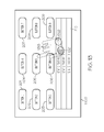
- FIGS 15-16 are frontal views of a touch screen in accordance with an eight exemplary embodiment
- FIG. 17 is a flow chart of a first method in accordance with the exemplary embodiments.
- FIG. 18 is a flow chart of a second method in accordance with the exemplary embodiments.
- processor devices can carry out the described operations, tasks, and functions by manipulating electrical signals representing data bits at memory locations in the system memory, as well as other processing of signals.
- the memory locations where data bits are maintained are physical locations that have particular electrical, magnetic, optical, or organic properties corresponding to the data bits.
- an embodiment of a system or a component may employ various integrated circuit components, e.g., memory elements, digital signal processing elements, logic elements, look-up tables, or the like, which may carry out a variety of functions under the control of one or more microprocessors or other control devices.
- various integrated circuit components e.g., memory elements, digital signal processing elements, logic elements, look-up tables, or the like, which may carry out a variety of functions under the control of one or more microprocessors or other control devices.
- a system and method are provided for stabilizing the hand of a user for the touching of interactive graphical items on a touch screen.
- the system comprises first circuitry configured to display at least one character through the display screen on each of a plurality of buttons, and second circuitry configured to sense touches applied to each of the plurality of buttons.
- a processor defines a region that is configured to ignore touches to a portion of the touch screen (prevents touches from being registered by underlying touch sensitive regions), which may include a portion of or all of one or more of the plurality of buttons.
- turbulence it is likely that the user's accuracy will be reduced and touch locations may miss the desired interactive graphical item rather than being on target as they would be under calm conditions or in stable operating environments. Placing a portion of the user's hand on the touch screen will stabilize the touching of the interactive graphical item so as to improve the user's chance of hitting the target.
- a first exemplary embodiment includes strategically placing two or more regions around the interactive graphical items, e.g., buttons. A portion of a hand is placed on one of the regions and a digit of the hand touches the desired button.
- a second exemplary embodiment comprises a larger shaped region in which a palm of a hand may be rested.
- a third exemplary embodiment has a target button identified by the gaze of the user, and a region strategically placed nearby.
- a fourth exemplary embodiment has a touch sensitive area identified by a gaze, with the remainder of the touch screen being non-sensitive to a touch.
- a fifth exemplary embodiment includes a viewport around a sensitive area, wherein the area around the viewport is non-sensitive.
- the viewport is sensitive to touch and may be sized and moved.
- a sixth exemplary embodiment designates a plurality of touch points derived from the placement of a hand on the touch screen to define a area that may be moved and sized with movement of the hand.
- a seventh exemplary embodiment determines areas sensed from the placement of a hand on the touch screen, and determines a region by combining the areas and the area therebetween.
- An eighth exemplary embodiment determines a region from a gesture made by the user.
- Each of the regions in the above described embodiments may be dragged to a better position for the touching of the button, and a button, or a portion thereof, beneath the regions may be viewed, but a touch thereto will be ignored.
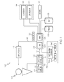
- a flight deck display system 100 includes a user interface 102, a processor 104, one or more terrain databases 106 sometimes referred to as a Terrain Avoidance and Warning System (TAWS), one or more navigation databases 108, sensors 112, external data sources 114, and one or more display devices 116.
- the user interface 102 is in operable communication with the processor 104 and is configured to receive input from a user 109 (e.g., a pilot) and, in response to the user input, supplies command signals to the processor 104.
- a user 109 e.g., a pilot
- the user interface 102 may be any one, or combination, of various known user interface devices including, but not limited to, one or more buttons, switches, or knobs (not shown).
- the user interface 102 includes a touch screen 107 and a touch screen controller 111.
- the touch screen controller 111 provides drive signals 113 to a touch screen 107, and a sense signal 115 is provided from the touch screen 107 to the touch screen controller 111, which periodically provides a controller signal 117 of the determination of a touch to the processor 104.
- the processor 104 interprets the controller signal 117, determines the application of the digit on the touch screen 107, and provides, for example, a controller signal 117 to the touch screen controller 111 and a signal 119 to the display device 116.
- the flight deck system 100 includes a gaze detecting system 130 comprising a gaze tracking controller 132 coupled between the processor 104 and each of an emitter 134 and a sensor 136, and in other exemplary embodiments, an accelerator 135.
- the processor 104 may be implemented or realized with a general purpose processor, a content addressable memory, a digital signal processor, an application specific integrated circuit, a field programmable gate array, any suitable programmable logic device, discrete gate or transistor logic, discrete hardware components, or any combination designed to perform the functions described herein.
- a processor device may be realized as a microprocessor, a controller, a microcontroller, or a state machine.
- a processor device may be implemented as a combination of computing devices, e.g., a combination of a digital signal processor and a microprocessor, a plurality of microprocessors, one or more microprocessors in conjunction with a digital signal processor core, or any other such configuration.
- the processor 104 includes on-board RAM (random access memory) 103, and on-board ROM (read-only memory) 105.
- the program instructions that control the processor 104 may be stored in either or both the RAM 103 and the ROM 105.
- the operating system software may be stored in the ROM 105
- various operating mode software routines and various operational parameters may be stored in the RAM 103.
- the software executing the exemplary embodiment is stored in either the ROM 105 or the RAM 103. It will be appreciated that this is merely exemplary of one scheme for storing operating system software and software routines, and that various other storage schemes may be implemented.
- the memory 103, 105 may be realized as RAM memory, flash memory, EPROM memory, EEPROM memory, registers, a hard disk, a removable disk, a CD-ROM, or any other form of storage medium known in the art.
- the memory 103, 105 can be coupled to the processor 104 such that the processor 104 can be read information from, and write information to, the memory 103, 105.
- the memory 103, 105 may be integral to the processor 104.
- the processor 104 and the memory 103, 105 may reside in an ASIC.
- a functional or logical module/component of the display system 100 might be realized using program code that is maintained in the memory 103, 105.
- the memory 103, 105 can be used to store data utilized to support the operation of the display system 100, as will become apparent from the following description.
- the processor 104 is in operable communication with the terrain databases 106, the navigation databases 108, and the display devices 116, and is coupled to receive various types of inertial data from the sensors 112, and various other avionics-related data from the external data sources 114.
- the processor 104 is configured, in response to the inertial data and the avionics-related data, to selectively retrieve terrain data from one or more of the terrain databases 106 and navigation data from one or more of the navigation databases 108, and to supply appropriate display commands to the display devices 116.
- the display devices 116 in response to the display commands, selectively render various types of textual, graphic, and/or iconic information.
- the terrain databases 106 include various types of data representative of the terrain over which the aircraft is flying, and the navigation databases 108 include various types of navigation-related data.
- the sensors 112 may be implemented using various types of inertial sensors, systems, and or subsystems, now known or developed in the future, for supplying various types of inertial data, for example, representative of the state of the aircraft including aircraft speed, heading, altitude, and attitude.
- the ILS 118 provides aircraft with horizontal (or localizer) and vertical (or glide slope) guidance just before and during landing and, at certain fixed points, indicates the distance to the reference point of landing on a particular runway.
- the GPS receiver 124 is a multi-channel receiver, with each channel tuned to receive one or more of the GPS broadcast signals transmitted by the constellation of GPS satellites (not illustrated) orbiting the earth.
- the display devices 116 in response to display commands supplied from the processor 104, selectively render various textual, graphic, and/or iconic information, and thereby supplies visual feedback to the user 109.
- the display device 116 may be implemented using any one of numerous known display devices suitable for rendering textual, graphic, and/or iconic information in a format viewable by the user 109.
- Non-limiting examples of such display devices include various cathode ray tube (CRT) displays, and various flat screen displays such as various types of LCD (liquid crystal display) and TFT (thin film transistor) displays.
- the display devices 116 may additionally be implemented as a screen mounted display, or any one of numerous known technologies.
- the display devices 116 may be configured as any one of numerous types of aircraft flight deck displays. For example, it may be configured as a multi-function display, a horizontal situation indicator, or a vertical situation indicator, just to name a few. In the depicted embodiment, however, one of the display devices 116 is configured as a primary flight display (PFD).
- PFD primary flight display
- the display device 116 is also configured to process the current flight status data for the host aircraft.
- the sources of flight status data generate, measure, and/or provide different types of data related to the operational status of the host aircraft, the environment in which the host aircraft is operating, flight parameters, and the like.
- the sources of flight status data may be realized using line replaceable units (LRUs), transducers, accelerometers, instruments, sensors, and other well known devices.
- LRUs line replaceable units
- the data provided by the sources of flight status data may include, without limitation: airspeed data; groundspeed data; altitude data; attitude data, including pitch data and roll data; yaw data; geographic position data, such as GPS data; time/date information; heading information; weather information; flight path data; track data; radar altitude data; geometric altitude data; wind speed data; wind direction data; etc.
- the display device 116 is suitably designed to process data obtained from the sources of flight status data in the manner described in more detail herein.
- touch screen sensing technologies including capacitive, resistive, infrared, surface acoustic wave, and embedded optical. All of these technologies sense touches on a screen.
- US patent 6,492,979 discloses the use of a combination of capacitive touch screen and force sensors
- US patent 7,196,694 discloses the use of force sensors at the peripherals of the touch screen to determine the position of a touch
- US patent publication 2007/0229464 discloses the use of a capacitive force sensor array, overlaying a display to form a touch screen. While a touch screen is described wherein the application of the touch is determined by a change in resistance, there are many other technologies available that could be used, including Infrared and capacitive.
- a touch screen having a plurality of buttons, each configured to display one or more symbols.
- a button as used herein is a defined visible location on the touch screen that encompasses the symbol(s). Symbols as used herein are defined to include alphanumeric characters, icons, signs, words, terms, and phrases, either alone or in combination. A particular symbol is selected by sensing the application (touch) of a digit, such as a finger or a stylus, to a touch-sensitive object associated with that symbol.
- a touch-sensitive object as used herein is a touch-sensitive location that includes a button and may extend around the button. Each button including a symbol has a touch-sensing object associated therewith for sensing the application of the digit or digits.
- a touch screen 200 includes a plurality of buttons 201-209, an optional text field 210, and at least one visible region 211-214 providing physical support to the interacting hand(s) of a user to improve the probability of touching a desired button 201-209 and for reducing fatigue. While four regions 211-214 are shown, any number of at least one may be provided.
- a user may rest a portion of a hand 215, such as a thumb, on one of the regions 211-214, for example region 213, to steady the hand 215 during a touching of one of the buttons 201-209 during turbulence, vibrations of the display, or the like.
- the regions 211-214 define an area configured by the processor to ignore touches to that portion of the touch screen (prevents touches from being registered by underlying touch sensitive regions).
- the location of the regions 211-214 are determined by the location of the buttons 201-209 and the distance required to reach the buttons 201-209, offering maximum accessibility to interactive graphical items (buttons 201-209) with minimum region 211-214 movement.
- a region 211-214 may be moved by the user touching a region 211-214 and dragging the touch across the screen 200 so as to place a digit over one of the buttons 201-209 without providing any unintended touch commands.
- the user has touched the region 213 (represented by the dotted region 213 in FIG. 3 ) and moved the region 213 up and to the left towards the desired button 204 (the region 213 being moved is numbered 213' and may be enlarged while being moved).
- the moving region 213' is in a position where the user may easily touch the desired button 306, the user stops moving the region 213'.
- the region 213' assumes its original shape as region 213" ( FIG. 4 ).
- region 211-214 When a region 211-214 overlies a button 201-209, such as region 213', 213" overlying button 205, that portion of the button 205 will not register a touch. Furthermore, the region 213' 213" is semi-transparent, allowing the user to see the button beneath the region 213', 213".
- the borders of the regions 211-214 are visible for the user to quickly perceive its geometry and available area to support an interacting hand. Furthermore, the border can be animated, for example, moving dashes, for easy recognition. Additionally, the regions 211-214 may be made available, for example, when the touch screen is displaying, when the user selects the option, or during unstable environments, for example, turbulence or vibrations as sensed by the accelerator 135 ( FIG. 1 ).
- the regions 211-214 are located in the lower half of the touch screen 200 in FIGS. 2-4 , they may be located anywhere on the touch screen 200.
- the non-sensitive regions 211-214 are strategically located in consideration of the location of the buttons 201-209 and in consideration of the shape of a user's hand 215.
- a touch screen 500 includes a region 511 having a rectangular shape of a size large enough to receive a palm of a hand 515, which may be more suitable for a large touch screen.
- the region 511 may be drug towards button 205, for example, so the user may touch the button 204 with a finger ( FIG. 6 ).
- the region 511 when the region 511 overlies a button 201-209, such as region 511 overlying button 206, that portion of the button 206 will not register a touch.
- the region 511 is semi-transparent, allowing the user to see the button beneath the region 511.
- the direction of a gaze (which portion of the touch screen 200, 500 is being viewed) of an aircraft member is determined.
- the flight deck controller includes a gaze tracking controller 132, an emitter 134, and a sensor 136.
- the emitter 134 is positioned on the head of the user for emitting a signal that is sensed by one or more sensors 136 positioned near the touch screen.
- the gaze tracking controller 132 in response to the sensed signal, communicates with the touch screen 102 to identify a portion of the touch screen being viewed.
- the gaze determining system 130 determines that the user is looking at button 208 and activates a region 711 in a position near the button 208 with appropriate offset and orientation.
- the user may place a digit from the hand 715 ( FIG. 8 ) on the region 711 and then touch button 208. If the region 711 is not close enough to the button 208, the user may drag the region 711 closer to the button 208. When the region 711 overlies a button 201-209, such as region 711 overlying button 209, that portion of the button 209 will not register a touch. Furthermore, the region 711 is semi-transparent, allowing the user to see the button 209 beneath the region 711. When the user is not looking at the touch screen 700 (the touch screen 700 is not in use), the region 711 does not appear.
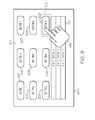
- the gaze determining system 130 determines that the user is looking at button 209 and activates a sensing area 912 around the button 209 and a region 911 (that prevents a touch from being registered) for the remainder of the touch screen 900.
- the user may place a digit, e.g., a thumb, a palm, or the like, from the hand 915 anywhere on the region 911 (anywhere on the touch screen 900 except for in the sensing region 912) and then touch button 209 with a digit.
- the boundary of the sensing area 912 may be displayed around a single or a group of graphical objects (buttons to indicate the augmented touch sensitive area corresponding to the gaze. For example, if the gaze target contains closely placed buttons like numeric entry or a keypad, the boundary would be displayed such that it surrounds all of the graphical objects.
- a manual method is provided for selecting, relocating, and resizing a touch sensitive zone 1022 for selecting one of the buttons 201-209 on the touch screen 1000.
- the area outside the viewport 1024 is a region 1011.
- the viewport 1024 may be manually instantiated, for example, by menu selection.
- the viewport 1024 defines a touch sensitive area that may be used for moving and resizing the viewport 1024.
- the user may place a digit, e.g., a thumb, a palm, or the like, from the hand 1015 anywhere on the region 1011 (anywhere on the touch screen 1000 except for within the outer boundary 1026 of the viewport 1024) and then touch button 205 with a digit.
- a button 201-209 such as region 1011 overlying buttons 201-203, 207-209
- that portion of the button will not register a touch.
- the region 1011 is semi-transparent, allowing the user to see the buttons 201-203, 207-209 beneath the region 1011.
- the viewport 1024 is semi-transparent, allowing the user to see the buttons 204-206 beneath the viewport 1024.
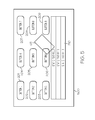
- touch points 1121-1125 are determined and a polygonal region 1111 is defined.
- the user may drag the hand 1115 ( FIG. 12 ) causing a new polygon region 1112 defined by the touch points 1125-1129 to where the user may touch the button 202, for example.
- the region 1111 overlies a button 201-209, such as region 1111 overlying button 206, that portion of the button 206 will not register a touch.
- the region 1111, 1112 is semi-transparent, allowing the user to see the buttons 206, 203 beneath the region 1111, 1112.
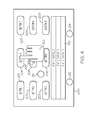
- the touch screen 1300 may sense two or more separate areas of the hand 1315 (dotted for illustration) placed on the touch screen 1300, thereby creating two or more regions 1321, 1322, and then combine these two or more regions 1321, 1322, including the area of the touch screen between the two or more areas, to form a combined single region 1323.
- the user creates a region 1511 by making a gesture 1510 on the touch screen 1500.
- the gesture 1510 for example a circular motion by a finger, may comprise any size or shape, and may be drug across the touch screen 1500 by the user to provide access to any of the buttons 201-209, for example, button 205 in FIG. 16 .
- FIGS. 17 and 18 are flow charts that illustrate exemplary embodiments of a touch screen 107 suitable for use with a flight deck system 100.
- Processes 1700 and 1800 represent two implementations of a method for stabilizing the hand for touching a desired button on an onboard display element of a host aircraft.
- the various tasks performed in connection with process 1700, 1800 may be performed by software, hardware, firmware, or any combination thereof.
- the following description of processes 1700, 1800 may refer to elements mentioned above in connection with the figures.
- portions of processes 1700, 1800 may be performed by different elements of the described system, e.g., a processor, a display element, or a data communication component.
- processes 1700, 1800 may include any number of additional or alternative tasks, the tasks shown in FIGS. 17, 18 need not be performed in the illustrated order, and processes 1700, 1800 may be incorporated into a more comprehensive procedure or process having additional functionality not described in detail herein. Moreover, one or more of the tasks shown in FIGS. 17, 18 could be omitted from an embodiment of the process 1700, 1800, respectively, as long as the intended overall functionality remains intact.
- the method includes preventing 1702 at least one button on a first portion of the touch screen from registering a touch; sensing 1704 a portion of a hand on the first portion; and sensing a touch 1706 of another of the plurality of buttons on a second portion of the touch screen.
- the method of FIG. 18 includes preventing 1802 a first portion of the touch screen from registering a touch, and sensing 1804 a touch to one of the plurality of buttons within a second portion of the touch screen
Abstract
Description
- This application claims the benefit of
U.S. Provisional Application No. 61/467,752 filed 25 March 2011 - The exemplary embodiments described herein generally relate to touch screens and more particularly to a method for providing stable touches to a touch screen.
- World wide air traffic is projected to double every ten to fourteen years and the International Civil Aviation Organization (ICAO) forecasts world air travel growth of five percent per annum until the year 2020. Such growth may have an influence on flight performance and may increase the workload of the flight crew. One such influence on flight performance has been the ability for the flight crew to input data while paying attention to other matters within and outside of the cockpit, especially during periods when movement makes it difficult to touch the panel in the desired manner or location. The ability to easily and quickly input data can significantly improve situational awareness of the flight crew.
- Many electronic devices, such as aircraft flight deck operational equipment, cursor control devices (CCDs), hard knobs, switches, and hardware keyboards, are increasingly being replaced by touch panels. A touch panel offers intuitive input for a computer or other data processing devices, but may be affected by movement of the touch panel and/or the pilot caused by, for example, turbulence, aircraft vibration, and/or G forces.
- Accordingly, it is desirable to provide a touch screen whose input is less subject to the movement turbulence, G forces, and/or equipment vibrations. Furthermore, other desirable features and characteristics of the exemplary embodiments will become apparent from the subsequent detailed description and the appended claims, taken in conjunction with the accompanying drawings and the foregoing technical field and background.
- A system and method are provided for a touch screen whose input is less subject to the movement turbulence, G forces, and/or equipment vibrations.
- In an exemplary embodiment, a method of selecting one of a plurality of buttons displayed on a touch screen includes preventing at least one button on a first portion of the touch screen from registering a touch; sensing a portion of a hand on the first portion; and sensing a touch on another of the plurality of buttons on a second portion of the touch screen.
- In another exemplary embodiment, a method of selecting one of a plurality of buttons displayed on a touch screen includes preventing a first portion of the touch screen from registering a touch, and sensing a touch to one of the plurality of buttons within a second portion of the touch screen.
- In yet another exemplary embodiment, a touch screen includes a display screen; first circuitry configured to display at least one character through the display screen on each of a plurality of buttons; second circuitry configured to sense touches applied to each of the plurality of buttons; and a processor configured to define a region in which a touch to at least a portion of an underlying button will be ignored.
- The present invention will hereinafter be described in conjunction with the following drawing figures, wherein like numerals denote like elements, and
-
FIG. 1 is a block diagram of an aircraft system including a touch screen display; -
FIGS. 2-4 are frontal views of a touch screen in accordance with a first exemplary embodiment; -
FIGS. 5-6 are frontal views of a touch screen in accordance with a second exemplary embodiment; -
FIGS. 7-8 are frontal views of a touch screen in accordance with a third exemplary embodiment; and -
FIG. 9 is a frontal view of a touch screen in accordance with a fourth exemplary embodiment; -
FIG. 10 is a frontal view of a touch screen in accordance with a fifth exemplary embodiment; -
FIGS. 11-12 are frontal views of a touch screen in accordance with a sixth exemplary embodiment; -
FIGS. 13-14 are frontal views of a touch screen in accordance with a seventh exemplary embodiment; -
FIGS 15-16 are frontal views of a touch screen in accordance with an eight exemplary embodiment; -
FIG. 17 is a flow chart of a first method in accordance with the exemplary embodiments; and -
FIG. 18 is a flow chart of a second method in accordance with the exemplary embodiments. - The following detailed description is merely illustrative in nature and is not intended to limit the embodiments of the subject matter or the application and uses of such embodiments. Any implementation described herein as exemplary is not necessarily to be construed as preferred or advantageous over other implementations. Furthermore, there is no intention to be bound by any expressed or implied theory presented in the preceding technical field, background, brief summary, or the following detailed description.
- Techniques and technologies may be described herein in terms of functional and/or logical block components, and with reference to symbolic representations of operations, processing tasks, and functions that may be performed by various computing components or devices. Such operations, tasks, and functions are sometimes referred to as being computer-executed, computerized, software-implemented, or computer-implemented. In practice, one or more processor devices can carry out the described operations, tasks, and functions by manipulating electrical signals representing data bits at memory locations in the system memory, as well as other processing of signals. The memory locations where data bits are maintained are physical locations that have particular electrical, magnetic, optical, or organic properties corresponding to the data bits. It should be appreciated that the various block components shown in the figures may be realized by any number of hardware, softwasre, and/or firmware components configured to perform the specified functions. For example, an embodiment of a system or a component may employ various integrated circuit components, e.g., memory elements, digital signal processing elements, logic elements, look-up tables, or the like, which may carry out a variety of functions under the control of one or more microprocessors or other control devices.
- For the sake of brevity, conventional techniques related to graphics and image processing, navigation, flight planning, aircraft controls, aircraft data communication systems, and other functional aspects of certain systems and subsystems (and the individual operating components thereof) may not be described in detail herein. Furthermore, the connecting lines shown in the various figures contained herein are intended to represent exemplary functional relationships and/or physical couplings between the various elements. It should be noted that many alternative or additional functional relationships or physical connections may be present in an embodiment of the subject matter.
- A system and method are provided for stabilizing the hand of a user for the touching of interactive graphical items on a touch screen. The system comprises first circuitry configured to display at least one character through the display screen on each of a plurality of buttons, and second circuitry configured to sense touches applied to each of the plurality of buttons. A processor defines a region that is configured to ignore touches to a portion of the touch screen (prevents touches from being registered by underlying touch sensitive regions), which may include a portion of or all of one or more of the plurality of buttons. In unstable operating environments, for example, turbulence, it is likely that the user's accuracy will be reduced and touch locations may miss the desired interactive graphical item rather than being on target as they would be under calm conditions or in stable operating environments. Placing a portion of the user's hand on the touch screen will stabilize the touching of the interactive graphical item so as to improve the user's chance of hitting the target.
- A first exemplary embodiment includes strategically placing two or more regions around the interactive graphical items, e.g., buttons. A portion of a hand is placed on one of the regions and a digit of the hand touches the desired button.
- A second exemplary embodiment comprises a larger shaped region in which a palm of a hand may be rested. A third exemplary embodiment has a target button identified by the gaze of the user, and a region strategically placed nearby. A fourth exemplary embodiment has a touch sensitive area identified by a gaze, with the remainder of the touch screen being non-sensitive to a touch.
- A fifth exemplary embodiment includes a viewport around a sensitive area, wherein the area around the viewport is non-sensitive. The viewport is sensitive to touch and may be sized and moved. A sixth exemplary embodiment designates a plurality of touch points derived from the placement of a hand on the touch screen to define a area that may be moved and sized with movement of the hand. A seventh exemplary embodiment determines areas sensed from the placement of a hand on the touch screen, and determines a region by combining the areas and the area therebetween. An eighth exemplary embodiment determines a region from a gesture made by the user.
- Each of the regions in the above described embodiments may be dragged to a better position for the touching of the button, and a button, or a portion thereof, beneath the regions may be viewed, but a touch thereto will be ignored.
- Though the method and touch screen of the exemplary embodiments may be used in any type of electronic device, for example, vehicles and heavy machinery, and small handheld mobile devices such as smart phones, the use in an aircraft system is described as an example. Referring to
FIG. 1 , a flightdeck display system 100 includes auser interface 102, aprocessor 104, one ormore terrain databases 106 sometimes referred to as a Terrain Avoidance and Warning System (TAWS), one ormore navigation databases 108,sensors 112,external data sources 114, and one ormore display devices 116. Theuser interface 102 is in operable communication with theprocessor 104 and is configured to receive input from a user 109 (e.g., a pilot) and, in response to the user input, supplies command signals to theprocessor 104. Theuser interface 102 may be any one, or combination, of various known user interface devices including, but not limited to, one or more buttons, switches, or knobs (not shown). In the depicted embodiment, theuser interface 102 includes atouch screen 107 and atouch screen controller 111. Thetouch screen controller 111 providesdrive signals 113 to atouch screen 107, and asense signal 115 is provided from thetouch screen 107 to thetouch screen controller 111, which periodically provides acontroller signal 117 of the determination of a touch to theprocessor 104. Theprocessor 104 interprets thecontroller signal 117, determines the application of the digit on thetouch screen 107, and provides, for example, acontroller signal 117 to thetouch screen controller 111 and asignal 119 to thedisplay device 116. Therefore, theuser 109 uses thetouch screen 107 to provide an input as more fully described hereinafter. Furthermore, in some exemplary embodiments, theflight deck system 100 includes agaze detecting system 130 comprising agaze tracking controller 132 coupled between theprocessor 104 and each of anemitter 134 and asensor 136, and in other exemplary embodiments, anaccelerator 135. - The
processor 104 may be implemented or realized with a general purpose processor, a content addressable memory, a digital signal processor, an application specific integrated circuit, a field programmable gate array, any suitable programmable logic device, discrete gate or transistor logic, discrete hardware components, or any combination designed to perform the functions described herein. A processor device may be realized as a microprocessor, a controller, a microcontroller, or a state machine. Moreover, a processor device may be implemented as a combination of computing devices, e.g., a combination of a digital signal processor and a microprocessor, a plurality of microprocessors, one or more microprocessors in conjunction with a digital signal processor core, or any other such configuration. In the depicted embodiment, theprocessor 104 includes on-board RAM (random access memory) 103, and on-board ROM (read-only memory) 105. The program instructions that control theprocessor 104 may be stored in either or both theRAM 103 and theROM 105. For example, the operating system software may be stored in theROM 105, whereas various operating mode software routines and various operational parameters may be stored in theRAM 103. The software executing the exemplary embodiment is stored in either theROM 105 or theRAM 103. It will be appreciated that this is merely exemplary of one scheme for storing operating system software and software routines, and that various other storage schemes may be implemented. - The
memory memory processor 104 such that theprocessor 104 can be read information from, and write information to, thememory memory processor 104. As an example, theprocessor 104 and thememory display system 100 might be realized using program code that is maintained in thememory memory display system 100, as will become apparent from the following description. - No matter how the
processor 104 is specifically implemented, it is in operable communication with theterrain databases 106, thenavigation databases 108, and thedisplay devices 116, and is coupled to receive various types of inertial data from thesensors 112, and various other avionics-related data from theexternal data sources 114. Theprocessor 104 is configured, in response to the inertial data and the avionics-related data, to selectively retrieve terrain data from one or more of theterrain databases 106 and navigation data from one or more of thenavigation databases 108, and to supply appropriate display commands to thedisplay devices 116. Thedisplay devices 116, in response to the display commands, selectively render various types of textual, graphic, and/or iconic information. - The
terrain databases 106 include various types of data representative of the terrain over which the aircraft is flying, and thenavigation databases 108 include various types of navigation-related data. Thesensors 112 may be implemented using various types of inertial sensors, systems, and or subsystems, now known or developed in the future, for supplying various types of inertial data, for example, representative of the state of the aircraft including aircraft speed, heading, altitude, and attitude. TheILS 118 provides aircraft with horizontal (or localizer) and vertical (or glide slope) guidance just before and during landing and, at certain fixed points, indicates the distance to the reference point of landing on a particular runway. The GPS receiver 124 is a multi-channel receiver, with each channel tuned to receive one or more of the GPS broadcast signals transmitted by the constellation of GPS satellites (not illustrated) orbiting the earth. - The
display devices 116, as noted above, in response to display commands supplied from theprocessor 104, selectively render various textual, graphic, and/or iconic information, and thereby supplies visual feedback to theuser 109. It will be appreciated that thedisplay device 116 may be implemented using any one of numerous known display devices suitable for rendering textual, graphic, and/or iconic information in a format viewable by theuser 109. Non-limiting examples of such display devices include various cathode ray tube (CRT) displays, and various flat screen displays such as various types of LCD (liquid crystal display) and TFT (thin film transistor) displays. Thedisplay devices 116 may additionally be implemented as a screen mounted display, or any one of numerous known technologies. It is additionally noted that thedisplay devices 116 may be configured as any one of numerous types of aircraft flight deck displays. For example, it may be configured as a multi-function display, a horizontal situation indicator, or a vertical situation indicator, just to name a few. In the depicted embodiment, however, one of thedisplay devices 116 is configured as a primary flight display (PFD). - In operation, the
display device 116 is also configured to process the current flight status data for the host aircraft. In this regard, the sources of flight status data generate, measure, and/or provide different types of data related to the operational status of the host aircraft, the environment in which the host aircraft is operating, flight parameters, and the like. In practice, the sources of flight status data may be realized using line replaceable units (LRUs), transducers, accelerometers, instruments, sensors, and other well known devices. The data provided by the sources of flight status data may include, without limitation: airspeed data; groundspeed data; altitude data; attitude data, including pitch data and roll data; yaw data; geographic position data, such as GPS data; time/date information; heading information; weather information; flight path data; track data; radar altitude data; geometric altitude data; wind speed data; wind direction data; etc. Thedisplay device 116 is suitably designed to process data obtained from the sources of flight status data in the manner described in more detail herein. - There are many types of touch screen sensing technologies, including capacitive, resistive, infrared, surface acoustic wave, and embedded optical. All of these technologies sense touches on a screen. For example,
US patent 6,492,979 discloses the use of a combination of capacitive touch screen and force sensors,US patent 7,196,694 discloses the use of force sensors at the peripherals of the touch screen to determine the position of a touch, andUS patent publication 2007/0229464 discloses the use of a capacitive force sensor array, overlaying a display to form a touch screen. While a touch screen is described wherein the application of the touch is determined by a change in resistance, there are many other technologies available that could be used, including Infrared and capacitive. - A touch screen is disclosed having a plurality of buttons, each configured to display one or more symbols. A button as used herein is a defined visible location on the touch screen that encompasses the symbol(s). Symbols as used herein are defined to include alphanumeric characters, icons, signs, words, terms, and phrases, either alone or in combination. A particular symbol is selected by sensing the application (touch) of a digit, such as a finger or a stylus, to a touch-sensitive object associated with that symbol. A touch-sensitive object as used herein is a touch-sensitive location that includes a button and may extend around the button. Each button including a symbol has a touch-sensing object associated therewith for sensing the application of the digit or digits.
- Referring to
FIG. 2 and in accordance with an exemplary embodiment, atouch screen 200 includes a plurality of buttons 201-209, anoptional text field 210, and at least one visible region 211-214 providing physical support to the interacting hand(s) of a user to improve the probability of touching a desired button 201-209 and for reducing fatigue. While four regions 211-214 are shown, any number of at least one may be provided. A user may rest a portion of ahand 215, such as a thumb, on one of the regions 211-214, forexample region 213, to steady thehand 215 during a touching of one of the buttons 201-209 during turbulence, vibrations of the display, or the like. The regions 211-214 define an area configured by the processor to ignore touches to that portion of the touch screen (prevents touches from being registered by underlying touch sensitive regions). The location of the regions 211-214 are determined by the location of the buttons 201-209 and the distance required to reach the buttons 201-209, offering maximum accessibility to interactive graphical items (buttons 201-209) with minimum region 211-214 movement. - In one exemplary embodiment, a region 211-214 may be moved by the user touching a region 211-214 and dragging the touch across the
screen 200 so as to place a digit over one of the buttons 201-209 without providing any unintended touch commands. For example, referring toFIG. 3 , the user has touched the region 213 (represented by the dottedregion 213 inFIG. 3 ) and moved theregion 213 up and to the left towards the desired button 204 (theregion 213 being moved is numbered 213' and may be enlarged while being moved). When the moving region 213' is in a position where the user may easily touch the desired button 306, the user stops moving the region 213'. When the movement ceases, the region 213' assumes its original shape asregion 213" (FIG. 4 ). When a region 211-214 overlies a button 201-209, such asregion 213', 213" overlyingbutton 205, that portion of thebutton 205 will not register a touch. Furthermore, the region 213' 213" is semi-transparent, allowing the user to see the button beneath theregion 213', 213". The borders of the regions 211-214 are visible for the user to quickly perceive its geometry and available area to support an interacting hand. Furthermore, the border can be animated, for example, moving dashes, for easy recognition. Additionally, the regions 211-214 may be made available, for example, when the touch screen is displaying, when the user selects the option, or during unstable environments, for example, turbulence or vibrations as sensed by the accelerator 135 (FIG. 1 ). - While the regions 211-214 are located in the lower half of the
touch screen 200 inFIGS. 2-4 , they may be located anywhere on thetouch screen 200. Preferably, the non-sensitive regions 211-214 are strategically located in consideration of the location of the buttons 201-209 and in consideration of the shape of a user'shand 215. - Furthermore, the regions 211-214 may assume any predetermined size and shape, which may be determined at software design or during runtime for the most appropriate use for the given usage context. For example, referring to
FIG. 5 , atouch screen 500 includes aregion 511 having a rectangular shape of a size large enough to receive a palm of ahand 515, which may be more suitable for a large touch screen. Theregion 511 may be drug towardsbutton 205, for example, so the user may touch thebutton 204 with a finger (FIG. 6 ). As in the previous embodiment, when theregion 511 overlies a button 201-209, such asregion 511overlying button 206, that portion of thebutton 206 will not register a touch. Furthermore, theregion 511 is semi-transparent, allowing the user to see the button beneath theregion 511. - In the following described embodiment, the direction of a gaze (which portion of the
touch screen gaze tracking controller 132, anemitter 134, and asensor 136. Theemitter 134 is positioned on the head of the user for emitting a signal that is sensed by one ormore sensors 136 positioned near the touch screen. Thegaze tracking controller 132, in response to the sensed signal, communicates with thetouch screen 102 to identify a portion of the touch screen being viewed. In one exemplary embodiment ofFIG. 7 , thegaze determining system 130 determines that the user is looking atbutton 208 and activates aregion 711 in a position near thebutton 208 with appropriate offset and orientation. The user may place a digit from the hand 715 (FIG. 8 ) on theregion 711 and then touchbutton 208. If theregion 711 is not close enough to thebutton 208, the user may drag theregion 711 closer to thebutton 208. When theregion 711 overlies a button 201-209, such asregion 711overlying button 209, that portion of thebutton 209 will not register a touch. Furthermore, theregion 711 is semi-transparent, allowing the user to see thebutton 209 beneath theregion 711. When the user is not looking at the touch screen 700 (thetouch screen 700 is not in use), theregion 711 does not appear. - In yet another exemplary embodiment of
FIG. 9 , thegaze determining system 130 determines that the user is looking atbutton 209 and activates asensing area 912 around thebutton 209 and a region 911 (that prevents a touch from being registered) for the remainder of thetouch screen 900. The user may place a digit, e.g., a thumb, a palm, or the like, from thehand 915 anywhere on the region 911 (anywhere on thetouch screen 900 except for in the sensing region 912) and then touchbutton 209 with a digit. The boundary of thesensing area 912 may be displayed around a single or a group of graphical objects (buttons to indicate the augmented touch sensitive area corresponding to the gaze. For example, if the gaze target contains closely placed buttons like numeric entry or a keypad, the boundary would be displayed such that it surrounds all of the graphical objects. - In still another exemplary embodiment (
FIG. 10 ), a manual method is provided for selecting, relocating, and resizing a touchsensitive zone 1022 for selecting one of the buttons 201-209 on thetouch screen 1000. Aviewport 1024 having anouter boundary 1026 and aninner boundary 1028 encompasses the touchsensitive zone 1022. The area outside theviewport 1024 is aregion 1011. Theviewport 1024 may be manually instantiated, for example, by menu selection. Theviewport 1024 defines a touch sensitive area that may be used for moving and resizing theviewport 1024. The user may place a digit, e.g., a thumb, a palm, or the like, from thehand 1015 anywhere on the region 1011 (anywhere on thetouch screen 1000 except for within theouter boundary 1026 of the viewport 1024) and then touchbutton 205 with a digit. When theregion 1011 overlies a button 201-209, such asregion 1011 overlying buttons 201-203, 207-209, that portion of the button will not register a touch. Furthermore, theregion 1011 is semi-transparent, allowing the user to see the buttons 201-203, 207-209 beneath theregion 1011. Likewise, theviewport 1024 is semi-transparent, allowing the user to see the buttons 204-206 beneath theviewport 1024. - When the user places a hand 1115 (dotted for illustration) on the
touch screen 1100 for the exemplary embodiment ofFIG. 11 , touch points 1121-1125 are determined and apolygonal region 1111 is defined. The user may drag the hand 1115 (FIG. 12 ) causing anew polygon region 1112 defined by the touch points 1125-1129 to where the user may touch thebutton 202, for example. When theregion 1111 overlies a button 201-209, such asregion 1111overlying button 206, that portion of thebutton 206 will not register a touch. Furthermore, theregion buttons region - In another exemplary embodiment of
FIGS. 13-14 , thetouch screen 1300 may sense two or more separate areas of the hand 1315 (dotted for illustration) placed on thetouch screen 1300, thereby creating two ormore regions 1321, 1322, and then combine these two ormore regions 1321, 1322, including the area of the touch screen between the two or more areas, to form a combinedsingle region 1323. - Referring to
FIGS. 15 and16 , the user creates aregion 1511 by making agesture 1510 on thetouch screen 1500. Thegesture 1510, for example a circular motion by a finger, may comprise any size or shape, and may be drug across thetouch screen 1500 by the user to provide access to any of the buttons 201-209, for example,button 205 inFIG. 16 . -
FIGS. 17 and 18 are flow charts that illustrate exemplary embodiments of atouch screen 107 suitable for use with aflight deck system 100.Processes process processes processes FIGS. 17, 18 need not be performed in the illustrated order, and processes 1700, 1800 may be incorporated into a more comprehensive procedure or process having additional functionality not described in detail herein. Moreover, one or more of the tasks shown inFIGS. 17, 18 could be omitted from an embodiment of theprocess - Referring to
FIG. 17 , the method includes preventing 1702 at least one button on a first portion of the touch screen from registering a touch; sensing 1704 a portion of a hand on the first portion; and sensing atouch 1706 of another of the plurality of buttons on a second portion of the touch screen. - The method of
FIG. 18 includes preventing 1802 a first portion of the touch screen from registering a touch, and sensing 1804 a touch to one of the plurality of buttons within a second portion of the touch screen - While at least one exemplary embodiment has been presented in the foregoing detailed description, it should be appreciated that a vast number of variations exist. It should also be appreciated that the exemplary embodiment or exemplary embodiments are only examples, and are not intended to limit the scope, applicability, or configuration of the invention in any way. Rather, the foregoing detailed description will provide those skilled in the art with a convenient road map for implementing an exemplary embodiment of the invention, it being understood that various changes may be made in the function and arrangement of elements described in an exemplary embodiment without departing from the scope of the invention as set forth in the appended claims.
Claims (15)
- A method of selecting one of a plurality of buttons displayed on a touch screen, comprising:preventing a first portion of the touch screen from registering a touch; andsensing a touch to one of the plurality of buttons within a second portion of the touch screen.
- The method of claim 1 wherein the preventing step comprises:providing a plurality of regions on the touch screen whose locations are based on the location of the plurality of buttons; andsensing a portion of a hand on one of the plurality of regions.
- The method of claim 2 further comprising:sensing the movement of one of the regions.
- The method of claim 3 further comprising:changing the shape of the region during the movement.
- The method of claim 4 further comprising:changing the region to its shape prior to the movement when the movement has ceased.
- The method of claim 1 wherein the preventing step comprises:providing a region of a size sufficient to receive a palm of a hand.
- The method of claim 1 further comprising:determining a button at which a user is gazing; andplacing a region on the touch screen based on the location of the button for which the gaze is directed.
- The method of claim 1 further comprising:determining a button at which a user is gazing; anddeactivating at least one other button from sensing a touch.
- The method of claim 1 further comprising:determining a button at which a user is gazing; anddefining a viewport surrounding the desired button.
- The method of claim 9 further comprising:moving the viewport by the application of a moving touch.
- The method of claim 1 wherein the preventing step comprises:sensing a touch of the touch screen to define a plurality of touch points that define a region.
- The method of claim 1 further comprising:sensing the movement of the hand to change the location and shape of the region.
- The method of claim 1 wherein the preventing step comprises:sensing a gesture of a user to define a region.
- A touch screen comprising:a display screen;first circuitry configured to display at least one character through the display screen on each of a plurality of buttons; andsecond circuitry configured to sense touches applied to each of the plurality of buttons; anda processor configured to:define a region in which a touch to at least a portion of an underlying button will be ignored.
- The touch screen of claim 14 wherein the processor is further configured to:determine a button at which a user is gazing; andplace a region on the touch screen based on the location of the button for which the gaze is directed.
Applications Claiming Priority (2)
| Application Number | Priority Date | Filing Date | Title |
|---|---|---|---|
| US201161467752P | 2011-03-25 | 2011-03-25 | |
| US13/162,679 US8766936B2 (en) | 2011-03-25 | 2011-06-17 | Touch screen and method for providing stable touches |
Publications (2)
| Publication Number | Publication Date |
|---|---|
| EP2503443A2 true EP2503443A2 (en) | 2012-09-26 |
| EP2503443A3 EP2503443A3 (en) | 2016-05-25 |
Family
ID=45928694
Family Applications (1)
| Application Number | Title | Priority Date | Filing Date |
|---|---|---|---|
| EP12160824.4A Withdrawn EP2503443A3 (en) | 2011-03-25 | 2012-03-22 | Touch screen and method for providing stable touches |
Country Status (6)
| Country | Link |
|---|---|
| US (1) | US8766936B2 (en) |
| EP (1) | EP2503443A3 (en) |
| JP (1) | JP2012203912A (en) |
| KR (1) | KR20120109403A (en) |
| CN (1) | CN102866797B (en) |
| TW (1) | TW201246034A (en) |
Cited By (6)
| Publication number | Priority date | Publication date | Assignee | Title |
|---|---|---|---|---|
| WO2014062246A1 (en) * | 2012-10-15 | 2014-04-24 | The Boeing Company | Turbulence mitigation for touch screen systems |
| CN103870059A (en) * | 2012-12-07 | 2014-06-18 | 霍尼韦尔国际公司 | System and method for interacting with touch screen interface utilizing intelligent stencil mask |
| FR3013861A1 (en) * | 2013-11-27 | 2015-05-29 | Airbus Operations Sas | METHOD FOR VALIDATING AN INTERACTION ON A TOUCH SURFACE BY OCCULOMETRY |
| EP2894545A1 (en) * | 2014-01-10 | 2015-07-15 | Samsung Electronics Co., Ltd | Method and apparatus for processing inputs in an electronic device |
| EP2829954A4 (en) * | 2012-03-23 | 2015-10-28 | Ntt Docomo Inc | Information terminal, method for controlling input acceptance, and program for controlling input acceptance |
| EP2939088A4 (en) * | 2012-12-28 | 2016-09-07 | Nokia Technologies Oy | Responding to user input gestures |
Families Citing this family (29)
| Publication number | Priority date | Publication date | Assignee | Title |
|---|---|---|---|---|
| JP5278461B2 (en) * | 2011-02-03 | 2013-09-04 | 株式会社デンソー | Gaze detection device and gaze detection method |
| US9345072B2 (en) * | 2012-01-11 | 2016-05-17 | General Electric Company | Induction cooking electromagnetic induced rejection methods |
| GB201203830D0 (en) * | 2012-03-05 | 2012-04-18 | Elliptic Laboratories As | Touchless user interfaces |
| US9733707B2 (en) | 2012-03-22 | 2017-08-15 | Honeywell International Inc. | Touch screen display user interface and method for improving touch interface utility on the same employing a rules-based masking system |
| US9423871B2 (en) | 2012-08-07 | 2016-08-23 | Honeywell International Inc. | System and method for reducing the effects of inadvertent touch on a touch screen controller |
| US20140062893A1 (en) * | 2012-08-28 | 2014-03-06 | Honeywell International Inc. | System and method for reducing the probability of accidental activation of control functions on a touch screen |
| US20140104191A1 (en) * | 2012-10-17 | 2014-04-17 | Perceptive Pixel, Inc. | Input Classification for Multi-Touch Systems |
| US20140152593A1 (en) * | 2012-12-03 | 2014-06-05 | Industrial Technology Research Institute | Method And System For Operating Portable Devices |
| CN103279218A (en) * | 2012-12-24 | 2013-09-04 | 李永贵 | Tablet computer without frame |
| US9658716B2 (en) * | 2013-02-12 | 2017-05-23 | Shenzhen Seefaa Scitech Co., Ltd. | Method and device of deactivating portion of touch screen to prevent accidental activation |
| US9542040B2 (en) * | 2013-03-15 | 2017-01-10 | Smart Technologies Ulc | Method for detection and rejection of pointer contacts in interactive input systems |
| JP2014194363A (en) * | 2013-03-28 | 2014-10-09 | Fujitsu Ltd | Guidance device, guidance method, and program |
| US20140300555A1 (en) * | 2013-04-05 | 2014-10-09 | Honeywell International Inc. | Avionic touchscreen control systems and program products having "no look" control selection feature |
| US20170115693A1 (en) * | 2013-04-25 | 2017-04-27 | Yonggui Li | Frameless Tablet |
| FR3011648B1 (en) * | 2013-10-07 | 2015-12-11 | Ece | METHOD AND TOUCH INTERFACE FOR CONTROLLING PROTECTED EQUIPMENT OR FUNCTION |
| US9114887B2 (en) * | 2013-10-31 | 2015-08-25 | Gulfstream Aerospace Corporation | Methods and systems for displaying aircraft information |
| WO2015065478A1 (en) * | 2013-11-01 | 2015-05-07 | Intel Corporation | Gaze-assisted touchscreen inputs |
| KR102278559B1 (en) * | 2013-12-30 | 2021-07-15 | 엘지디스플레이 주식회사 | Touch module and Method for detecting touch position |
| CN104808836B (en) * | 2014-01-23 | 2017-12-01 | 京瓷办公信息系统株式会社 | Electronic equipment and operation assisting method |
| US9588611B2 (en) | 2015-01-19 | 2017-03-07 | Honeywell International Inc. | System and method for guarding emergency and critical touch targets |
| US10340593B2 (en) | 2016-02-25 | 2019-07-02 | Raytheon Company | Systems and methods for phased array beam control |
| US9817511B1 (en) * | 2016-09-16 | 2017-11-14 | International Business Machines Corporation | Reaching any touch screen portion with one hand |
| US10338812B2 (en) | 2017-01-10 | 2019-07-02 | International Business Machines Corporation | Replacement of physical buttons with virtual controls |
| US10649555B2 (en) * | 2017-09-28 | 2020-05-12 | Htc Corporation | Input interface device, control method and non-transitory computer-readable medium |
| CN109101110A (en) * | 2018-08-10 | 2018-12-28 | 北京七鑫易维信息技术有限公司 | A kind of method for executing operating instructions, device, user terminal and storage medium |
| US10768699B2 (en) * | 2018-09-10 | 2020-09-08 | Lenovo (Singapore) Pte. Ltd. | Presentation to user of indication of object at which another person is looking |
| US20200192485A1 (en) * | 2018-12-12 | 2020-06-18 | Lenovo (Singapore) Pte. Ltd. | Gaze-based gesture recognition |
| US11568640B2 (en) | 2019-09-30 | 2023-01-31 | Lenovo (Singapore) Pte. Ltd. | Techniques for providing vibrations at headset |
| US11144759B1 (en) * | 2020-05-12 | 2021-10-12 | Lenovo (Singapore) Pte. Ltd. | Presentation of graphical objects on display based on input from rear-facing camera |
Citations (3)
| Publication number | Priority date | Publication date | Assignee | Title |
|---|---|---|---|---|
| US6492979B1 (en) | 1999-09-07 | 2002-12-10 | Elo Touchsystems, Inc. | Dual sensor touchscreen utilizing projective-capacitive and force touch sensors |
| US7196694B2 (en) | 2001-04-13 | 2007-03-27 | 3M Innovative Properties Company | Force sensors and touch panels using same |
| US20070229464A1 (en) | 2006-03-30 | 2007-10-04 | Apple Computer, Inc. | Force Imaging Input Device and System |
Family Cites Families (104)
| Publication number | Priority date | Publication date | Assignee | Title |
|---|---|---|---|---|
| US5128672A (en) | 1990-10-30 | 1992-07-07 | Apple Computer, Inc. | Dynamic predictive keyboard |
| US7489303B1 (en) | 2001-02-22 | 2009-02-10 | Pryor Timothy R | Reconfigurable instrument panels |
| US6160536A (en) | 1995-03-27 | 2000-12-12 | Forest; Donald K. | Dwell time indication method and apparatus |
| US5956020A (en) | 1995-07-27 | 1999-09-21 | Microtouch Systems, Inc. | Touchscreen controller with pen and/or finger inputs |
| US5764222A (en) | 1996-05-28 | 1998-06-09 | International Business Machines Corporation | Virtual pointing device for touchscreens |
| US5689619A (en) | 1996-08-09 | 1997-11-18 | The United States Of America As Represented By The Secretary Of The Army | Eyetracker control of heads-up displays |
| US5870083A (en) | 1996-10-04 | 1999-02-09 | International Business Machines Corporation | Breakaway touchscreen pointing device |
| US7834855B2 (en) | 2004-08-25 | 2010-11-16 | Apple Inc. | Wide touchpad on a portable computer |
| EP1717684A3 (en) | 1998-01-26 | 2008-01-23 | Fingerworks, Inc. | Method and apparatus for integrating manual input |
| US6181328B1 (en) | 1998-03-02 | 2001-01-30 | International Business Machines Corporation | Method and system for calibrating touch screen sensitivities according to particular physical characteristics associated with a user |
| US7030863B2 (en) * | 2000-05-26 | 2006-04-18 | America Online, Incorporated | Virtual keyboard system with automatic correction |
| US6459424B1 (en) | 1999-08-10 | 2002-10-01 | Hewlett-Packard Company | Touch-sensitive input screen having regional sensitivity and resolution properties |
| US6636897B1 (en) | 1999-09-28 | 2003-10-21 | Microsoft Corporation | Selective information subset synchronization based on single user action |
| US7289102B2 (en) | 2000-07-17 | 2007-10-30 | Microsoft Corporation | Method and apparatus using multiple sensors in a device with a display |
| JP2002287889A (en) * | 2001-03-23 | 2002-10-04 | Sharp Corp | Pen input device |
| US7730401B2 (en) | 2001-05-16 | 2010-06-01 | Synaptics Incorporated | Touch screen with user interface enhancement |
| US7895522B2 (en) | 2001-09-28 | 2011-02-22 | Ntt Docomo, Inc. | Layout of platform specific graphical user interface widgets migrated between heterogeneous device platforms |
| TW528981B (en) | 2001-10-25 | 2003-04-21 | Compal Electronics Inc | Portable computer and related method for preventing input interruption by write-tracking input region |
| US7023427B2 (en) | 2002-06-28 | 2006-04-04 | Microsoft Corporation | Method and system for detecting multiple touches on a touch-sensitive screen |
| US20040150626A1 (en) | 2003-01-30 | 2004-08-05 | Raymond Husman | Operator interface panel with control for visibility of desplayed objects |
| US20040212601A1 (en) | 2003-04-24 | 2004-10-28 | Anthony Cake | Method and apparatus for improving accuracy of touch screen input devices |
| KR100522940B1 (en) * | 2003-07-25 | 2005-10-24 | 삼성전자주식회사 | Touch screen system having active area setting function and control method thereof |
| US7499040B2 (en) | 2003-08-18 | 2009-03-03 | Apple Inc. | Movable touch pad with added functionality |
| US9274598B2 (en) | 2003-08-25 | 2016-03-01 | International Business Machines Corporation | System and method for selecting and activating a target object using a combination of eye gaze and key presses |
| US7411575B2 (en) | 2003-09-16 | 2008-08-12 | Smart Technologies Ulc | Gesture recognition method and touch system incorporating the same |
| US7176902B2 (en) | 2003-10-10 | 2007-02-13 | 3M Innovative Properties Company | Wake-on-touch for vibration sensing touch input devices |
| US7942743B2 (en) | 2004-01-20 | 2011-05-17 | Nintendo Co., Ltd. | Game apparatus and storage medium storing game program |
| US7561143B1 (en) | 2004-03-19 | 2009-07-14 | The University of the Arts | Using gaze actions to interact with a display |
| US7653883B2 (en) | 2004-07-30 | 2010-01-26 | Apple Inc. | Proximity detector in handheld device |
| US7847789B2 (en) | 2004-11-23 | 2010-12-07 | Microsoft Corporation | Reducing accidental touch-sensitive device activation |
| US20060221061A1 (en) | 2005-03-31 | 2006-10-05 | Tyco Electronic Corporation | Touch sensor and control with random pulse spacing |
| US9019209B2 (en) | 2005-06-08 | 2015-04-28 | 3M Innovative Properties Company | Touch location determination involving multiple touch location processes |
| US8018440B2 (en) | 2005-12-30 | 2011-09-13 | Microsoft Corporation | Unintentional touch rejection |
| GB0605386D0 (en) * | 2006-03-17 | 2006-04-26 | Malvern Scient Solutions Ltd | Character input method |
| KR100866484B1 (en) | 2006-05-17 | 2008-11-03 | 삼성전자주식회사 | Apparatus and method for sensing movement of fingers using multi-touch sensor arrays |
| US7693869B2 (en) | 2006-09-06 | 2010-04-06 | International Business Machines Corporation | Method and apparatus for using item dwell time to manage a set of items |
| US20080100586A1 (en) | 2006-10-26 | 2008-05-01 | Deere & Company | Method and system for calibrating a touch screen |
| US8269727B2 (en) | 2007-01-03 | 2012-09-18 | Apple Inc. | Irregular input identification |
| KR100881186B1 (en) | 2007-01-04 | 2009-02-05 | 삼성전자주식회사 | Touch screen display device |
| US20080284739A1 (en) | 2007-05-17 | 2008-11-20 | Microsoft Corporation | Human Interface Device |
| US8085252B1 (en) | 2007-05-29 | 2011-12-27 | Cypress Semiconductor Corporation | Method and apparatus to determine direction of motion in a sensor array of a touch sensing device |
| JP2009025858A (en) * | 2007-07-17 | 2009-02-05 | Kyocera Mita Corp | Electronic apparatus |
| US20090058819A1 (en) | 2007-08-31 | 2009-03-05 | Richard Gioscia | Soft-user interface feature provided in combination with pressable display surface |
| US8587559B2 (en) | 2007-09-28 | 2013-11-19 | Samsung Electronics Co., Ltd. | Multipoint nanostructure-film touch screen |
| ITBO20070820A1 (en) | 2007-12-13 | 2009-06-14 | Technogym Spa | GINNICA MACHINE WITH ADAPTIVE INTERFACE. |
| JP4990753B2 (en) | 2007-12-28 | 2012-08-01 | パナソニック株式会社 | Electronic device input device, input operation processing method, and input control program |
| US20090174676A1 (en) | 2008-01-04 | 2009-07-09 | Apple Inc. | Motion component dominance factors for motion locking of touch sensor data |
| US20090174679A1 (en) * | 2008-01-04 | 2009-07-09 | Wayne Carl Westerman | Selective Rejection of Touch Contacts in an Edge Region of a Touch Surface |
| JP5383053B2 (en) * | 2008-01-29 | 2014-01-08 | 京セラ株式会社 | Terminal device with display function |
| TW200943140A (en) | 2008-04-02 | 2009-10-16 | Asustek Comp Inc | Electronic apparatus and control method thereof |
| TWI366776B (en) | 2008-04-21 | 2012-06-21 | Htc Corp | Operating method and system and stroage device using the same |
| US8526767B2 (en) | 2008-05-01 | 2013-09-03 | Atmel Corporation | Gesture recognition |
| JP4982430B2 (en) | 2008-05-27 | 2012-07-25 | 株式会社エヌ・ティ・ティ・ドコモ | Character input device and character input method |
| WO2009150285A1 (en) | 2008-06-10 | 2009-12-17 | Nokia Corporation | Touch button false activation suppression |
| US8754855B2 (en) | 2008-06-27 | 2014-06-17 | Microsoft Corporation | Virtual touchpad |
| JP4672756B2 (en) | 2008-06-30 | 2011-04-20 | 株式会社東芝 | Electronics |
| DE102008035090B4 (en) | 2008-07-28 | 2010-09-23 | Airbus Deutschland Gmbh | Flexible passenger cabin control unit for controlling cabin functions, aircraft and their use |
| TW201011605A (en) | 2008-09-01 | 2010-03-16 | Turbotouch Technology Inc E | Method capable of preventing mistakenly triggering a touch panel |
| EP2175352A3 (en) | 2008-10-07 | 2010-05-05 | Research In Motion Limited | Portable electronic device and method of controlling same |
| KR100971501B1 (en) | 2008-10-24 | 2010-07-21 | 주식회사 애트랩 | Touch sensor device |
| US8856690B2 (en) | 2008-10-31 | 2014-10-07 | Sprint Communications Company L.P. | Associating gestures on a touch screen with characters |
| US8502787B2 (en) | 2008-11-26 | 2013-08-06 | Panasonic Corporation | System and method for differentiating between intended and unintended user input on a touchpad |
| KR101050642B1 (en) | 2008-12-04 | 2011-07-19 | 삼성전자주식회사 | Watch phone and method of conducting call in watch phone |
| US20100146459A1 (en) | 2008-12-08 | 2010-06-10 | Mikko Repka | Apparatus and Method for Influencing Application Window Functionality Based on Characteristics of Touch Initiated User Interface Manipulations |
| KR101030398B1 (en) | 2008-12-15 | 2011-04-20 | 삼성전자주식회사 | Touch sensitivity changeable touch sensor depending on user interface mode of terminal and the providing method thereof |
| KR101534109B1 (en) | 2008-12-23 | 2015-07-07 | 삼성전자주식회사 | Capacitive touch panel and touch system having the same |
| US8291348B2 (en) | 2008-12-31 | 2012-10-16 | Hewlett-Packard Development Company, L.P. | Computing device and method for selecting display regions responsive to non-discrete directional input actions and intelligent content analysis |
| US8279184B2 (en) | 2009-01-27 | 2012-10-02 | Research In Motion Limited | Electronic device including a touchscreen and method |
| JP4771183B2 (en) | 2009-01-30 | 2011-09-14 | 株式会社デンソー | Operating device |
| CN101794179B (en) * | 2009-02-04 | 2012-01-25 | 倚天资讯股份有限公司 | Electronic device with touch function |
| US8570290B2 (en) * | 2009-02-06 | 2013-10-29 | Panasonic Corporation | Image display device |
| TWI378382B (en) | 2009-02-13 | 2012-12-01 | Htc Corp | Method, apparatus and computer program product for preventing on-screen buttons from being mistakenly touched |
| DE102010009607A1 (en) | 2009-02-27 | 2010-09-30 | Stoneridge Control Devices, Inc., Canton | Touch-sensitive sensor system for B-column of automobile, has memory i.e. cache-memory, connected with controller for storing code in time interval and providing code in another time interval, which is initiated after ending former interval |
| US8570280B2 (en) | 2009-03-25 | 2013-10-29 | Lenovo (Singapore) Pte. Ltd. | Filtering of inadvertent contact with touch pad input device |
| WO2010118292A1 (en) | 2009-04-09 | 2010-10-14 | Dynavox Systems, Llc | Calibration free, motion tolerant eye-gaze direction detector with contextually aware computer interaction and communication methods |
| KR101537706B1 (en) | 2009-04-16 | 2015-07-20 | 엘지전자 주식회사 | Mobile terminal and control method thereof |
| KR20100118366A (en) | 2009-04-28 | 2010-11-05 | 삼성전자주식회사 | Operating method of touch screen and portable device including the same |
| US9354751B2 (en) | 2009-05-15 | 2016-05-31 | Apple Inc. | Input device with optimized capacitive sensing |
| US20110006996A1 (en) | 2009-07-08 | 2011-01-13 | Smith Nathan J | Private data entry |
| TW201104531A (en) | 2009-07-17 | 2011-02-01 | Egalax Empia Technology Inc | Method and device for palm rejection |
| US8279189B2 (en) | 2009-08-11 | 2012-10-02 | Atmel Corporation | Touch-sensitive user interface |
| US9696856B2 (en) | 2009-09-29 | 2017-07-04 | Elo Touch Solutions, Inc. | Method and apparatus for detecting simultaneous touch events on a bending-wave touchscreen |
| US10068728B2 (en) | 2009-10-15 | 2018-09-04 | Synaptics Incorporated | Touchpad with capacitive force sensing |
| US8587532B2 (en) | 2009-12-18 | 2013-11-19 | Intel Corporation | Multi-feature interactive touch user interface |
| US9507418B2 (en) | 2010-01-21 | 2016-11-29 | Tobii Ab | Eye tracker based contextual action |
| JP5556423B2 (en) * | 2010-01-29 | 2014-07-23 | ブラザー工業株式会社 | Input device and input control program |
| US20110187651A1 (en) | 2010-02-03 | 2011-08-04 | Honeywell International Inc. | Touch screen having adaptive input parameter |
| US20110214162A1 (en) | 2010-02-26 | 2011-09-01 | Nokia Corporation | Method and appartus for providing cooperative enablement of user input options |
| US9361018B2 (en) | 2010-03-01 | 2016-06-07 | Blackberry Limited | Method of providing tactile feedback and apparatus |
| US9740364B2 (en) | 2010-05-03 | 2017-08-22 | Microsoft Technology Licensing, Llc | Computer with graphical user interface for interaction |
| US20110283241A1 (en) | 2010-05-14 | 2011-11-17 | Google Inc. | Touch Gesture Actions From A Device's Lock Screen |
| US9411459B2 (en) | 2010-05-19 | 2016-08-09 | Lg Electronics Inc. | Mobile terminal and control method thereof |
| US8797280B2 (en) | 2010-05-26 | 2014-08-05 | Atmel Corporation | Systems and methods for improved touch screen response |
| US9946459B2 (en) | 2010-05-28 | 2018-04-17 | Lenovo (Singapore) Pte. Ltd. | Systems and methods for determining intentional touch screen contact |
| JP5501992B2 (en) | 2010-05-28 | 2014-05-28 | パナソニック株式会社 | Information terminal, screen component display method, program, and recording medium |
| US20110310001A1 (en) | 2010-06-16 | 2011-12-22 | Visteon Global Technologies, Inc | Display reconfiguration based on face/eye tracking |
| US8674959B2 (en) | 2010-06-28 | 2014-03-18 | Intel Corporation | Dynamic bezel for a mobile device |
| KR101667586B1 (en) * | 2010-07-12 | 2016-10-19 | 엘지전자 주식회사 | Mobile terminal and method for controlling the same |
| JP5618665B2 (en) | 2010-07-16 | 2014-11-05 | キヤノン株式会社 | Control device, control method, and program |
| FR2963121B1 (en) | 2010-07-22 | 2014-04-11 | Airbus Operations Sas | METHOD AND DEVICE FOR PROTECTING SOFTWARE CONTROLS IN AN AIRCRAFT COCKPIT |
| FR2963690B1 (en) | 2010-08-06 | 2012-08-03 | Thales Sa | SECURE CLIENT-SERVER COMPUTER SYSTEM FOR INTERACTIVE APPLICATIONS |
| US8994646B2 (en) | 2010-12-17 | 2015-03-31 | Microsoft Corporation | Detecting gestures involving intentional movement of a computing device |
| US9285950B2 (en) | 2011-03-30 | 2016-03-15 | Google Inc. | Hover-over gesturing on mobile devices |
| US9141280B2 (en) | 2011-11-09 | 2015-09-22 | Blackberry Limited | Touch-sensitive display method and apparatus |
-
2011
- 2011-06-17 US US13/162,679 patent/US8766936B2/en not_active Expired - Fee Related
-
2012
- 2012-03-22 EP EP12160824.4A patent/EP2503443A3/en not_active Withdrawn
- 2012-03-23 TW TW101110261A patent/TW201246034A/en unknown
- 2012-03-23 JP JP2012067414A patent/JP2012203912A/en active Pending
- 2012-03-23 KR KR1020120030040A patent/KR20120109403A/en not_active Application Discontinuation
- 2012-03-24 CN CN201210161700.XA patent/CN102866797B/en not_active Expired - Fee Related
Patent Citations (3)
| Publication number | Priority date | Publication date | Assignee | Title |
|---|---|---|---|---|
| US6492979B1 (en) | 1999-09-07 | 2002-12-10 | Elo Touchsystems, Inc. | Dual sensor touchscreen utilizing projective-capacitive and force touch sensors |
| US7196694B2 (en) | 2001-04-13 | 2007-03-27 | 3M Innovative Properties Company | Force sensors and touch panels using same |
| US20070229464A1 (en) | 2006-03-30 | 2007-10-04 | Apple Computer, Inc. | Force Imaging Input Device and System |
Cited By (11)
| Publication number | Priority date | Publication date | Assignee | Title |
|---|---|---|---|---|
| EP2829954A4 (en) * | 2012-03-23 | 2015-10-28 | Ntt Docomo Inc | Information terminal, method for controlling input acceptance, and program for controlling input acceptance |
| WO2014062246A1 (en) * | 2012-10-15 | 2014-04-24 | The Boeing Company | Turbulence mitigation for touch screen systems |
| US8825234B2 (en) | 2012-10-15 | 2014-09-02 | The Boeing Company | Turbulence mitigation for touch screen systems |
| CN104718522A (en) * | 2012-10-15 | 2015-06-17 | 波音公司 | Turbulence mitigation for touch screen systems |
| JP2018060553A (en) * | 2012-10-15 | 2018-04-12 | ザ・ボーイング・カンパニーThe Boeing Company | Turbulence mitigation for touch screen systems |
| CN104718522B (en) * | 2012-10-15 | 2019-05-28 | 波音公司 | The alleviation of jolting of touch-screen system |
| CN103870059A (en) * | 2012-12-07 | 2014-06-18 | 霍尼韦尔国际公司 | System and method for interacting with touch screen interface utilizing intelligent stencil mask |
| CN103870059B (en) * | 2012-12-07 | 2018-06-05 | 霍尼韦尔国际公司 | For the system and method interacted using intelligent template mask with touch screen interface |
| EP2939088A4 (en) * | 2012-12-28 | 2016-09-07 | Nokia Technologies Oy | Responding to user input gestures |
| FR3013861A1 (en) * | 2013-11-27 | 2015-05-29 | Airbus Operations Sas | METHOD FOR VALIDATING AN INTERACTION ON A TOUCH SURFACE BY OCCULOMETRY |
| EP2894545A1 (en) * | 2014-01-10 | 2015-07-15 | Samsung Electronics Co., Ltd | Method and apparatus for processing inputs in an electronic device |
Also Published As
| Publication number | Publication date |
|---|---|
| US8766936B2 (en) | 2014-07-01 |
| EP2503443A3 (en) | 2016-05-25 |
| TW201246034A (en) | 2012-11-16 |
| CN102866797A (en) | 2013-01-09 |
| JP2012203912A (en) | 2012-10-22 |
| KR20120109403A (en) | 2012-10-08 |
| US20120242591A1 (en) | 2012-09-27 |
| CN102866797B (en) | 2017-09-08 |
Similar Documents
| Publication | Publication Date | Title |
|---|---|---|
| US8766936B2 (en) | Touch screen and method for providing stable touches | |
| EP2383642B1 (en) | Touch screen and method for adjusting screen objects | |
| EP3246810B1 (en) | System and method of knob operation for touchscreen devices | |
| JP6242964B2 (en) | How to magnify characters displayed on an adaptive touchscreen keypad | |
| US20110187651A1 (en) | Touch screen having adaptive input parameter | |
| EP2787428A1 (en) | Avionic touchscreen control systems and program products having no look control selection feature | |
| US8159464B1 (en) | Enhanced flight display with improved touchscreen interface | |
| US9128580B2 (en) | System and method for interacting with a touch screen interface utilizing an intelligent stencil mask | |
| EP2555105A2 (en) | Touch screen having adaptive input requirements | |
| US20140240242A1 (en) | System and method for interacting with a touch screen interface utilizing a hover gesture controller | |
| US20110128235A1 (en) | Big key touch input device | |
| EP2818994A1 (en) | Touch screen and method for adjusting touch sensitive object placement thereon | |
| EP2767891A2 (en) | Slider control for graphical user interface and method for use thereof | |
| US9671868B2 (en) | System and method for volumetric computing |
Legal Events
| Date | Code | Title | Description |
|---|---|---|---|
| PUAI | Public reference made under article 153(3) epc to a published international application that has entered the european phase |
Free format text: ORIGINAL CODE: 0009012 |
|
| 17P | Request for examination filed |
Effective date: 20120322 |
|
| AK | Designated contracting states |
Kind code of ref document: A2 Designated state(s): AL AT BE BG CH CY CZ DE DK EE ES FI FR GB GR HR HU IE IS IT LI LT LU LV MC MK MT NL NO PL PT RO RS SE SI SK SM TR |
|
| AX | Request for extension of the european patent |
Extension state: BA ME |
|
| RAP1 | Party data changed (applicant data changed or rights of an application transferred) |
Owner name: HONEYWELL INTERNATIONAL INC. |
|
| PUAL | Search report despatched |
Free format text: ORIGINAL CODE: 0009013 |
|
| AK | Designated contracting states |
Kind code of ref document: A3 Designated state(s): AL AT BE BG CH CY CZ DE DK EE ES FI FR GB GR HR HU IE IS IT LI LT LU LV MC MK MT NL NO PL PT RO RS SE SI SK SM TR |
|
| AX | Request for extension of the european patent |
Extension state: BA ME |
|
| RIC1 | Information provided on ipc code assigned before grant |
Ipc: G06F 3/01 20060101ALI20160419BHEP Ipc: G06F 3/048 20060101AFI20160419BHEP |
|
| 17Q | First examination report despatched |
Effective date: 20160511 |
|
| GRAJ | Information related to disapproval of communication of intention to grant by the applicant or resumption of examination proceedings by the epo deleted |
Free format text: ORIGINAL CODE: EPIDOSDIGR1 |
|
| GRAP | Despatch of communication of intention to grant a patent |
Free format text: ORIGINAL CODE: EPIDOSNIGR1 |
|
| GRAP | Despatch of communication of intention to grant a patent |
Free format text: ORIGINAL CODE: EPIDOSNIGR1 |
|
| INTG | Intention to grant announced |
Effective date: 20190411 |
|
| STAA | Information on the status of an ep patent application or granted ep patent |
Free format text: STATUS: THE APPLICATION IS DEEMED TO BE WITHDRAWN |
|
| 18D | Application deemed to be withdrawn |
Effective date: 20190822 |
|
| P01 | Opt-out of the competence of the unified patent court (upc) registered |
Effective date: 20230525 |