EP2501523B1 - Manually guided press device - Google Patents
Manually guided press device Download PDFInfo
- Publication number
- EP2501523B1 EP2501523B1 EP10781667.0A EP10781667A EP2501523B1 EP 2501523 B1 EP2501523 B1 EP 2501523B1 EP 10781667 A EP10781667 A EP 10781667A EP 2501523 B1 EP2501523 B1 EP 2501523B1
- Authority
- EP
- European Patent Office
- Prior art keywords
- pressing
- electric motor
- motor
- manually guided
- control device
- Prior art date
- Legal status (The legal status is an assumption and is not a legal conclusion. Google has not performed a legal analysis and makes no representation as to the accuracy of the status listed.)
- Active
Links
- 238000004804 winding Methods 0.000 claims description 2
- 238000000034 method Methods 0.000 claims 1
- 238000006243 chemical reaction Methods 0.000 description 9
- 230000005540 biological transmission Effects 0.000 description 6
- 238000012423 maintenance Methods 0.000 description 6
- 230000006835 compression Effects 0.000 description 2
- 238000007906 compression Methods 0.000 description 2
- 230000007423 decrease Effects 0.000 description 2
- 238000013461 design Methods 0.000 description 2
- 239000012530 fluid Substances 0.000 description 2
- 244000089486 Phragmites australis subsp australis Species 0.000 description 1
- 230000006978 adaptation Effects 0.000 description 1
- 238000010276 construction Methods 0.000 description 1
- 238000002788 crimping Methods 0.000 description 1
- 238000011161 development Methods 0.000 description 1
- 238000006073 displacement reaction Methods 0.000 description 1
- 238000010438 heat treatment Methods 0.000 description 1
- 238000011835 investigation Methods 0.000 description 1
- 238000004519 manufacturing process Methods 0.000 description 1
- 238000012544 monitoring process Methods 0.000 description 1
- 230000003287 optical effect Effects 0.000 description 1
- 238000005086 pumping Methods 0.000 description 1
Images

Classifications
-
- B—PERFORMING OPERATIONS; TRANSPORTING
- B25—HAND TOOLS; PORTABLE POWER-DRIVEN TOOLS; MANIPULATORS
- B25B—TOOLS OR BENCH DEVICES NOT OTHERWISE PROVIDED FOR, FOR FASTENING, CONNECTING, DISENGAGING OR HOLDING
- B25B27/00—Hand tools, specially adapted for fitting together or separating parts or objects whether or not involving some deformation, not otherwise provided for
- B25B27/02—Hand tools, specially adapted for fitting together or separating parts or objects whether or not involving some deformation, not otherwise provided for for connecting objects by press fit or detaching same
- B25B27/10—Hand tools, specially adapted for fitting together or separating parts or objects whether or not involving some deformation, not otherwise provided for for connecting objects by press fit or detaching same inserting fittings into hoses
-
- B—PERFORMING OPERATIONS; TRANSPORTING
- B21—MECHANICAL METAL-WORKING WITHOUT ESSENTIALLY REMOVING MATERIAL; PUNCHING METAL
- B21D—WORKING OR PROCESSING OF SHEET METAL OR METAL TUBES, RODS OR PROFILES WITHOUT ESSENTIALLY REMOVING MATERIAL; PUNCHING METAL
- B21D39/00—Application of procedures in order to connect objects or parts, e.g. coating with sheet metal otherwise than by plating; Tube expanders
- B21D39/04—Application of procedures in order to connect objects or parts, e.g. coating with sheet metal otherwise than by plating; Tube expanders of tubes with tubes; of tubes with rods
- B21D39/048—Application of procedures in order to connect objects or parts, e.g. coating with sheet metal otherwise than by plating; Tube expanders of tubes with tubes; of tubes with rods using presses for radially crimping tubular elements
-
- Y—GENERAL TAGGING OF NEW TECHNOLOGICAL DEVELOPMENTS; GENERAL TAGGING OF CROSS-SECTIONAL TECHNOLOGIES SPANNING OVER SEVERAL SECTIONS OF THE IPC; TECHNICAL SUBJECTS COVERED BY FORMER USPC CROSS-REFERENCE ART COLLECTIONS [XRACs] AND DIGESTS
- Y10—TECHNICAL SUBJECTS COVERED BY FORMER USPC
- Y10T—TECHNICAL SUBJECTS COVERED BY FORMER US CLASSIFICATION
- Y10T29/00—Metal working
- Y10T29/53—Means to assemble or disassemble
- Y10T29/5367—Coupling to conduit
Landscapes
- Engineering & Computer Science (AREA)
- Mechanical Engineering (AREA)
- Control Of Motors That Do Not Use Commutators (AREA)
- Auxiliary Devices For And Details Of Packaging Control (AREA)
- Battery Mounting, Suspending (AREA)
- Press Drives And Press Lines (AREA)
- Control Of Presses (AREA)
Description
Die Erfindung betrifft ein handgeführtes Pressgerät zum Verbinden von zwei Werkstücken. Insbesondere ist das erfindungsgemäße Pressgerät zum Verbinden eines Rohrs mit einem Pressfitting durch Verpressen geeignet. Ferner betrifft die Erfindung handgeführte Presswerkzeuge zum Verpressen von Kabelschuhen.The invention relates to a hand-held pressing device for connecting two workpieces. In particular, the pressing device according to the invention is suitable for connecting a pipe to a press fitting by pressing. Furthermore, the invention relates hand-held pressing tools for pressing cable lugs.
Derartige handgeführte Pressgeräte weisen ein Presswerkzeug mit mehreren Pressbacken auf. Die Pressbacken umschließen bei einem Presswerkzeug für Rohrverbindungen das über das Rohr gesteckte Pressfitting. Durch Schließen der Pressbacken erfolgt ein Verformen bzw. Verpressen des Pressfittings und des Rohrs. Bei Presswerkzeugen für Kabelschuhe werden diese durch Schließen von Pressbacken verpresst, wobei der Kabelschuh zwischen mindestens zwei Pressbacken angeordnet ist. Eine der Pressbacken kann hierbei feststehend sein. Zur Erzeugung der erforderlichen hohen Presskräfte ist das Presswerkzeug mit einer üblicherweise elektrohydraulischen oder elektromechanischem Umwandlungseinrichtung verbunden. Die Umwandlungseinrichtung wird in der Regel über einen Elektromotor unter Zwischenschaltung eines Getriebes angetrieben. Eine hydraulische Umwandlungseinrichtung weist eine Hydraulikpumpe auf, bei der es sich üblicherweise um eine Kolbenpumpe oder eine Zahnradpumpe handelt. Die Pumpe wird von einem Bürstenmotor angetrieben. Die eingesetzten Pumpen, durch die ein hohes Drehmoment erzeugt werden muss, verlangen bauartbedingt eine relativ geringe Antriebsdrehzahl von üblicherweise 2.000 bis 5.000 Umdrehungen pro Minute. Da der Bürstenmotor jedoch mit erheblich höheren Drehzahlen betrieben wird, ist zwischen dem Motor und der Pumpe ein Untersetzungsgetriebe angeordnet. Bei einer hydraulischen Umwandlungseinrichtung wird durch das von der Pumpe geförderte Hydraulikmedium ein Arbeitskolben verschoben. Der Arbeitskolben ist mit den Pressbacken verbunden, so dass über den Arbeitskolben hohe Presskräfte auf die Pressbacken übertragen werden können. Sobald die eingestellte bzw. vorgegebene maximale Presskraft erreicht ist, wird die zur Betätigung des Arbeitskolbens vorgesehene Druckkammer durch ein üblicherweise als Nadelventil ausgebildetes Ventil geöffnet, so dass eine schlagartige Druckreduzierung in der Druckkammer erfolgt. Die Druckreduzierung führt zu einer Drehzahlerhöhung der Pumpe, die über einen Drehzahlsensor detektiert wird und zu einem automatischen Abschalten des Elektromotors führt. Über eine Rückstellfeder erfolgt sodann ein Zurückdrücken des Arbeitskolbens und somit ein Öffnen der Pressbacken.Such hand-held pressing devices have a pressing tool with several pressing jaws. The press jaws enclose the press fitting inserted over the pipe in a press tool for pipe connections. By closing the pressing jaws a deformation or pressing of the press fitting and the tube takes place. In pressing tools for cable lugs these are pressed by closing of pressing jaws, the lug is arranged between at least two pressing jaws. One of the press jaws can be fixed here. To generate the required high pressing forces, the pressing tool is connected to a usually electro-hydraulic or electromechanical conversion device. The conversion device is usually driven by an electric motor with the interposition of a transmission. A hydraulic conversion device has a hydraulic pump in which it is Usually is a piston pump or a gear pump. The pump is driven by a brush motor. The pumps used, through which a high torque must be generated, require a design-related relatively low drive speed of usually 2,000 to 5,000 revolutions per minute. However, since the brush motor operates at significantly higher speeds, a reduction gear is interposed between the motor and the pump. In a hydraulic conversion device, a working piston is displaced by the hydraulic medium conveyed by the pump. The working piston is connected to the pressing jaws so that high pressing forces can be transmitted to the pressing jaws via the working piston. As soon as the set or predetermined maximum pressing force is reached, the pressure chamber provided for actuating the working piston is opened by a valve, which is usually designed as a needle valve, so that a sudden pressure reduction takes place in the pressure chamber. The pressure reduction leads to a speed increase of the pump, which is detected by a speed sensor and leads to an automatic shutdown of the electric motor. A return spring is then used to push back the working piston and thus open the pressing jaws.
Aus
Derartige handgeführte Pressgeräte müssen in regelmäßigen Intervallen gewartet werden. Untersuchungen haben gezeigt, dass das das Wartungsintervall bestimmende Bauteil der Bürstenmotor ist. Aufgrund des häufigen Anfahrens unter Last sowie aufgrund des Vorsehens von Stoppfunktionen, bei denen über die Bürste ein Kurzschluss erzeugt wird, sind die Bürsten des Bürstenmotors sehr starkem Verschleiß ausgesetzt.Such hand-held pressing devices must be maintained at regular intervals. Investigations have shown that the maintenance interval determining component is the brush motor. Due to the frequent start-up under load and due to the provision of stop functions, in which a short circuit is generated via the brush, the brushes of the brush motor are exposed to very heavy wear.
Aufgabe der Erfindung ist es, ein handgeführtes Pressgerät zu schaffen, bei dem längere Wartungsintervalle realisiert sind.The object of the invention is to provide a hand-held pressing device, are realized in the longer maintenance intervals.
Die Lösung der Aufgabe erfolgt erfindungsgemäß durch die Merkmale des Anspruchs 1.The object is achieved according to the invention by the features of claim 1.
Das erfindungsgemäße handgeführte Pressgerät zum Verbinden eines Rohrs mit einem Pressfitting durch Verpressen weist ein Presswerkzeug mit mehreren Pressbacken auf. Das Presswerkzeug wird über einen Elektromotor unter Zwischenschaltung einer Umwandlungseinrichtung angetrieben. Bei der Umwandlungseinrichtung handelt es sich insbesondere um eine elektrohydraulische oder elektromechanische Umwandlungseinrichtung. Erfindungsgemäß handelt es sich bei dem Elektromotor um einen bürstenlosen Elektromotor. Ein bürstenloser Elektromotor hat gegenüber den in bekannten Presswerkzeugen verwendeten Bürstenmotor den erheblichen Vorteil, dass keine verschleißanfälligen Bürsten vorgesehen sind. Durch das Verwenden eines bürstenlosen Elektromotors können die aufgrund der starken Belastungen mit hohem Verschleiß belasteten Bürsten entfallen. Hierdurch ist es möglich, die Wartungszyklen deutlich zu verlängern. Die Anzahl der zwischen zwei Wartungen durchführbaren Verpressungen kann insbesondere mindestens verdoppelt oder gar verdreifacht werden. Ein erfindungsgemäßer Vorteil des Einsatzes eines bürstenlosen Elektromotors zum Betreiben des Pressgerätes besteht darin, dass durch einen bürstenlosen Elektromotor bzw. die Steuereinrichtung des bürstenlosen Elektromotors Zusatzfunktionen auf einfache Weise realisiert werden können. So erfolgt bei der Erfindung über eine mit dem Elektromotor verbundene oder in diesen integrierte Steuereinrichtung eine Steuerung der Drehzahl, die erforderlich ist um ein gewünschtes Drehmoment bzw. eine gewünschte Presskraft zu erzeugen. Erfindungsgemäß erfolgt mittels der Steuereinrichtung eine Bestimmung der aktuellen Motordrehzahl und der Elektromotor wird bei einem Drehzahlanstieg abgeschaltet.The hand-held pressing device according to the invention for connecting a pipe to a press fitting by pressing has a pressing tool with several pressing jaws. The pressing tool is driven by an electric motor with the interposition of a conversion device. The conversion device is, in particular, an electrohydraulic or electromechanical conversion device. According to the invention, the electric motor is a brushless electric motor. A brushless electric motor has the considerable advantage over the brush motor used in known pressing tools that no wear-prone brushes are provided. By using a brushless electric motor can be omitted due to the heavy loads with high wear brushes. This makes it possible to significantly extend the maintenance cycles. The number of compressions that can be carried out between two maintenance operations can in particular be at least doubled or even tripled. An inventive advantage of the use of a brushless electric motor for operating the pressing device is that additional functions can be realized in a simple manner by a brushless electric motor or the control device of the brushless electric motor. Thus, in the invention, control of the rotational speed, which is required to produce a desired torque or a desired pressing force, takes place via a control device connected to or integrated into the electric motor. According to the invention, by means of the control device, a determination of the current engine speed and the electric motor is turned off at a speed increase.
Ferner hat das erfindungsgemäße Verwenden eines bürstenlosen Elektromotors den Vorteil, dass die Wartungskosten reduziert werden, da ein Austausch der Bürsten oder des gesamten Bürstenmotors nicht erforderlich ist.Furthermore, the use of a brushless electric motor according to the invention has the advantage that the maintenance costs are reduced, since replacement of the brushes or the entire brush motor is not required.
Bei dem Elektromotor handelt es sich um einen Außen- oder Innenläufer-Motor. Vorzugsweise handelt es sich bei dem Elektromotor um einen bürstenlosen Außenläufermotor. Außenläufermotoren haben gegenüber bürstenlosen Innenläufermotoren den Vorteil, dass diese langsamer drehen und ein höheres Drehmoment bei gleicher Gesamtabmessung aufweisen. Beispielsweise weist ein siebenpoliger Außenläufermotor einen Stator mit zwölf Nuten auf, wobei jede zweite Nut bewickelt ist. Hieraus folgt, dass sich das Feld beim Wechseln der Phase um 60° dreht. Die den Stator umgebende Glocke bzw. der Außenläufer weist in diesem Beispiel vierzehn Magnete bzw. sieben Polpaare auf, die über 360° verteilt angeordnet sind. Beim Wechsel der Phase bewegt sich der Außenläufer siebenmal langsamer als das Feld, so dass sich der Außenläufer bei einer Bewegung des Feldes um 60° lediglich um 8,57° dreht. Hierdurch ist bei einem Außenläufer eine geringe Drehzahl realisiert.The electric motor is an external or internal rotor motor. Preferably, the electric motor is a brushless external rotor motor. External rotor motors have the advantage over brushless internal rotor motors that they rotate slower and have a higher torque with the same overall dimension. For example, a seven-pole external rotor motor has a stator with twelve slots, each second slot being wound. It follows that the field rotates by 60 ° when changing the phase. The bell surrounding the stator or the external rotor in this example has fourteen magnets or seven pole pairs, which are arranged distributed over 360 °. When changing the Phase, the external rotor moves seven times slower than the field, so that the outer rotor rotates by a movement of the field by 60 ° by only 8.57 °. As a result, a low speed is realized in an external rotor.
Bei einer besonders bevorzugten Ausführungsform ist der bürstenlose Elektromotor unmittelbar mit der Umwandeleinrichtung verbunden. Ein beim Verwenden von Bürstenmotoren zwingend erforderliches Untersetzungsgetriebe kann in dieser bevorzugten erfindungsgemäßen Weiterbildung entfallen. Beim Vorsehen einer elektrohydraulischen Umwandlungseinrichtung ist es somit besonders bevorzugt, dass die Abtriebswelle des Elektromotors unmittelbar mit der Hydraulikpumpe, d.h. mit der Antriebswelle der Hydraulikpumpe verbunden ist. Aufgrund des in dieser Ausführungsform möglichen Verzichts auf das Getriebe können die Kosten reduziert werden. Insbesondere kann jedoch der erforderliche Bauraum erheblich reduziert werden. Ein besonderer Vorteil der Verwendung des bürstenlosen Motors unter Weglassung oder starker Vereinfachung eines Untersetzungsgetriebes besteht darin, dass der Wirkungsgrad erheblich verbessert werden kann. Insbesondere aufgrund der in dem Getriebe auftretenden Reibung treten Verluste auf, die durch eine starke Vereinfachung oder sogar durch das vollständige Weglassen des Getriebes stark reduziert werden können. Durch ein Weglassen des Getriebes, was bei Verwenden eines bürstenlosen Motors möglich ist, kann eine Steigerung des Wirkungsgrades von insbesondere über 20% und besonders bevorzugt über 25% erzielt werden. Dies hat den Vorteil, dass die Betriebsdauer bei Verwendung desselben Akkus erheblich verlängert werden kann oder, bei gleicher Betriebsdauer, ein kleinerer und damit leichterer Akku eingesetzt werden kann. Ein weiterer Vorteil der Vereinfachung oder Weglassung des Getriebes liegt darin, dass eine erheblich geringere Geräuschentwicklung erfolgt. Auch sind die auftretenden Vibrationen sowie die hervorgerufene Erwärmung geringer.In a particularly preferred embodiment, the brushless electric motor is directly connected to the converter. A mandatory when using brush motors reduction gear can be omitted in this preferred embodiment of the invention. When providing an electro-hydraulic conversion device, it is thus particularly preferred that the output shaft of the electric motor is connected directly to the hydraulic pump, ie to the drive shaft of the hydraulic pump. Due to the possible omission of the transmission in this embodiment, the cost can be reduced. In particular, however, the required space can be significantly reduced. A particular advantage of using the brushless motor with omission or greatly simplifying a reduction gear is that the efficiency can be significantly improved. In particular, due to the friction occurring in the transmission losses occur which can be greatly reduced by a great simplification or even by completely omitting the transmission. By omitting the transmission, which is possible when using a brushless motor, an increase in the efficiency of in particular over 20% and particularly preferably over 25% can be achieved. This has the advantage that the operating time can be extended considerably when using the same battery or, for the same operating time, a smaller and thus lighter battery can be used. Another advantage of the simplification or omission of the transmission is that a considerably lower noise is generated. Also, the vibrations occurring and the heating caused are less.
Vorzugsweise ist die Abtriebswelle des Elektromotors derart angeordnet, dass sie zur Antriebswelle der Hydraulikpumpe koaxial ist. Hierdurch kann eine einfache Verbindung der Wellen bei geringem Bauraum realisiert werden.Preferably, the output shaft of the electric motor is arranged such that it is coaxial with the drive shaft of the hydraulic pump. As a result, a simple connection of the shafts can be realized in a small space.
Erfindungsgemäß erfolgt über eine mit dem Elektromotor verbundene oder in diesen integrierte Steuereinrichtung eine Bestimmung der aktuellen Drehzahl. Beispielsweise kann durch die in die Wicklungen induzierte Spannung ein Rückschluss auf die Motordrehzahl erfolgen. Hierdurch ist es möglich, auf einfache Weise zu detektieren, dass sich die Motordrehzahl erhöht. Ein sprunghafter Anstieg der Motordrehzahl erfolgt beim Öffnen des Druckventils, d.h. sobald die geforderte Presskraft erreicht ist. Dieser Drehzahlanstieg des Motors kann auf einfache Weise über die Steuereinrichtung bestimmt werden und zum Abschalten des Elektromotors genutzt werden. Der bei bekannten Pressgeräten erforderliche Drehzahlsensor, der zur Bestimmung des Drehzahlanstiegs beim Öffnen des Ventils zwingend notwendig ist, kann durch die erfindungsgemäße Verwendung eines bürstenlosen Elektromotors entfallen. Hierdurch können die Herstellungskosten reduziert werden. Insbesondere weist dies den Vorteil auf, dass ein für die Funktion des Pressgeräts wichtiges Bauteil durch die Steuereinrichtung des Motors ersetzt ist und hierdurch eine erheblich zuverlässigere Drehzahlbestimmung erfolgt. Ein Ausfallen des Drehzahlsensors, der zu einem erheblichen Beschädigen des Presswerkzeugs führen kann, kann nicht mehr auftreten.According to the invention, a determination of the current rotational speed takes place via a control device connected to or integrated into the electric motor. For example, the voltage induced in the windings can be used to draw conclusions about the engine speed. This makes it possible to detect in a simple manner that the engine speed increases. A sudden increase in the engine speed occurs when opening the pressure valve, ie as soon as the required pressing force is reached. This speed increase of the motor can be determined in a simple manner via the control device and used to switch off the electric motor. The speed sensor required in known pressing devices, which is absolutely necessary for determining the speed increase when opening the valve, can be eliminated by the inventive use of a brushless electric motor. As a result, the manufacturing cost can be reduced. In particular, this has the advantage that an important for the function of the pressing device component is replaced by the control device of the engine and thereby a much more reliable speed determination is carried out. Failure of the speed sensor, which can lead to significant damage to the pressing tool, can no longer occur.
Bei einer weiteren bevorzugten Ausführungsform erfolgt unmittelbar über die Parameter des bürstenlosen Elektromotors eine Bestimmung bzw. Berechnung des Motordrehmoments und/ oder der von den Pressbacken erzeugten Presskraft. Hierdurch ist es auf einfache Weise möglich, bei Erreichen der gewünschten bzw. eingestellten Presskraft automatisch ein Abschalten des Elektromotors zu realisieren. Insbesondere kann ggf. das die Druckkammer bei herkömmlichen Pressgeräten öffnende Ventil entfallen oder zumindest stark vereinfacht werden. Das Ventil, das bei bekannten Pressgeräten bei Erreichen der Presskraft geöffnet wird, kann bei dieser bevorzugten Ausführungsform zumindest derart vereinfacht werden, dass es sich nur noch um ein Notfallventil handelt, durch das ein Beschädigen des Pressgeräts beim Ausfall der Steuereinrichtung vermieden ist.In a further preferred embodiment, a determination or calculation of the engine torque and / or the pressing force generated by the pressing jaws takes place directly via the parameters of the brushless electric motor. As a result, it is possible in a simple manner to automatically realize a shutdown of the electric motor upon reaching the desired or set pressing force. In particular, if necessary, the valve which opens the pressure chamber in conventional pressing devices can be omitted or at least greatly simplified. The valve, which is opened in known pressing devices upon reaching the pressing force, can be simplified in this preferred embodiment, at least in such a way that it is only an emergency valve, which avoids damaging the pressing device in the event of failure of the control device.
Ein weiterer Vorteil des Verwendens eines bürstenlosen Elektromotors, insbesondere in Verbindung mit der bereits vorhandenen oder mit dem Elektromotor verbundenen Steuereinrichtung, besteht darin, dass bei Erreichen der eingestellten Presskraft oder bei Auftreten von Fehlern ein Abbremsen des Motors durch entsprechende Steuerbefehle bzw. durch Software erfolgen kann. Der bei Bürstenmotoren auftretende hohe Verschleiß, der beim Bremsen des Motors über den erzeugten Kurzschluss erfolgt, kann somit vermieden werden.Another advantage of using a brushless electric motor, in particular in connection with the already existing or connected to the electric motor control device, is that upon reaching the set pressing force or when errors occur, the motor can be decelerated by appropriate control commands or by software , The high wear occurring in brush motors, which occurs when braking the motor via the generated short circuit, can thus be avoided.
Ein weiterer Vorteil des Verwendens eines bürstenlosen Elektromotors besteht darin, dass eine sensorlose Kommutierung möglich ist. Das Vorsehen störanfälliger Drehzahlgeber zur Presskraftüberwachung bzw. zur Ablaufsteuerung ist daher nicht mehr notwendig.Another advantage of using a brushless electric motor is that sensorless commutation is possible. The provision of error-prone tachometer for pressing force monitoring or flow control is therefore no longer necessary.
In bevorzugter Weiterbildung des Pressgeräts ist eine Einstelleinrichtung vorgesehen. Mit Hilfe der Einstelleinrichtung können beispielsweise über Tasten und ein Display Pressparameter auf einfache Weise eingegeben werden. Diese werden an die Steuereinrichtung des Elektromotors übertragen, so dass eine unmittelbare einfache Steuerung des Elektromotors und damit des gesamten Pressgerätes möglich ist. Je nach Ausgestaltung der Steuereinrichtung und der durch die Steuereinrichtung bestimmten Parameter ist es somit möglich, dass die gewünschte Presskraft lediglich über die Einstelleinrichtung eingegeben werden muss. Eine mechanische Veränderung, durch die beispielsweise der Druckpunkt, an dem das Ventil öffnet, variiert wird, ist nicht erforderlich. Insofern ist der Aufbau des Pressgeräts erheblich vereinfacht. Ferner entfallen mechanische Bauteile, die, insbesondere aufgrund der auftretenden hohen Kräfte, ggf. beschädigt werden oder zumindest wartungsintensiver sind.In a preferred development of the pressing device, an adjustment device is provided. With the aid of the adjustment device, pressing parameters can be entered in a simple manner, for example, via keys and a display. These are transmitted to the control device of the electric motor, so that an immediate simple control of the electric motor and thus the entire pressing device is possible. Depending on the configuration of the control device and the parameters determined by the control device, it is thus possible for the desired pressing force to be input only via the setting device. A mechanical change by which, for example, the pressure point at which the valve opens is varied is not required. In this respect, the construction of the pressing device is considerably simplified. Furthermore, eliminates mechanical components that, in particular due to the high forces that occur, possibly damaged or at least maintenance-intensive.
Bei einer besonders bevorzugten Weiterbildung der Erfindung ist es beispielsweise über die Einstelleinrichtung möglich, die Art des verwendeten Presswerkzeugs einzugeben. Dies hat den Vorteil, dass ein handgeführtes Pressgerät vorgesehen werden kann, bei dem das Presswerkzeug auswechselbar ist. Eine aufwändige Anpassung des Pressgeräts an das Presswerkzeug ist hierbei nicht mehr erforderlich. Es ist lediglich erforderlich, beispielsweise eine Kennziffer des Presswerkzeuges einzugeben. In besonders bevorzugter Weiterbildung erfolgt ein automatisches Erkennen der Art des Presswerkzeugs durch das Pressgerät. Dies kann durch eine Kennzeichnung des Presswerkzeugs erfolgen, die insbesondere automatisch von der Steuereinrichtung erfasst wird. Der Benutzer kann somit das Presswerkzeug auswechseln und muss nicht darauf achten, dass die entsprechenden Pressparameter angepasst werden. Hierdurch ist beispielsweise vermieden, dass die für ein bestimmtes Presswerkzeug maximal zulässige Presskraft überschritten wird.In a particularly preferred embodiment of the invention, it is possible, for example via the setting, to enter the type of pressing tool used. This has the advantage that a hand-held pressing device can be provided, in which the pressing tool is replaceable. A complex adaptation of the pressing device to the pressing tool is no longer necessary. It is only necessary to enter, for example, a code of the pressing tool. In a particularly preferred embodiment, an automatic recognition of the type of pressing tool by the pressing device. This can be done by an identification of the pressing tool, which is detected in particular automatically by the control device. The user can thus replace the pressing tool and does not have to take care that the corresponding pressing parameters are adjusted. As a result, it is avoided, for example, that the maximum permissible pressing force for a particular pressing tool is exceeded.
Bei einer weiteren bevorzugten Ausführungsform der Erfindung ist mit der Steuereinrichtung des bürstenlosen Elektromotors eine Signalausgabeeinrichtung verbunden. Durch die Signalausgabeeinrichtung kann auf einfache Weise das Fertigstellen der Verpressung signalisiert werden. Auch das Auftreten von Störungen oder das Erfordernis, eine Wartung durchzuführen, kann durch die Signalausgabeeinrichtung signalisiert werden. Bei der Signalausgabeeinrichtung kann es sich um eine akustische und/ oder taktile (Vibration) Signalausgabeeinrichtung handeln. Die insbesondere akustische Signalausgabe kann hierbei unmittelbar durch die Steuereinrichtung verwirklicht werden. Zusätzlich kann die Signalausgabeeinrichtung auch ein Display aufweisen.In a further preferred embodiment of the invention, a signal output device is connected to the control device of the brushless electric motor. By the signal output device can be signaled in a simple way the completion of the compression. Also, the occurrence of disturbances or the need to perform maintenance can be signaled by the signal output device. The signal output device may be an acoustic and / or tactile (vibration) signal output device. The particular acoustic signal output can in this case be realized directly by the control device. In addition, the signal output device may also have a display.
Erfindungsgemäß wird das handgeführte Pressgerät in bevorzugter Ausführungsform derart betrieben, dass die mit dem Elektromotor verbundene Steuereinrichtung, wie vorstehend beschrieben, zum Bestimmen der Drehzahl und/ oder des Drehmoments und/ oder anderer Pressparameter verwendet wird. Zusätzlich kann die Steuereinrichtung auch zum Steuern einer Signalausgabeeinrichtung verwendet werden.According to the invention, the hand-held pressing device is operated in a preferred embodiment such that the control device connected to the electric motor, as described above, is used for determining the rotational speed and / or the torque and / or other pressing parameters. In addition, the controller may also be used to control a signal output device.
Nachfolgend wird die Erfindung anhand bevorzugter Ausführungsformen unter Bezugnahme auf die anliegenden Zeichnungen näher erläutert.The invention will be explained in more detail below with reference to preferred embodiments with reference to the accompanying drawings.
Es zeigen:
- Fig. 1
- eine schematische Schnittansicht einer erfindungsgemäßen Ausführungsform eines handgeführten Pressgeräts Zum Verbinden eines Rohrs mit einem Pressfitting durch Verpressen, und
- Fig. 2
- eine schematische Seitenansicht einer erfindungsgemäßen Ausführungsform eines handgeführten Pressgeräts zum Verpressen von Kabelschuhen.
- Fig. 1
- a schematic sectional view of an embodiment of a hand-held pressing device according to the invention For connecting a pipe with a press fitting by pressing, and
- Fig. 2
- a schematic side view of an embodiment of the invention of a hand-held pressing device for pressing cable lugs.
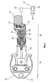
Das handgeführte Pressgerät zum Verbinden von Rohren mittels eines Pressfittings durch Verpressen (
Über ein Steuerventil 18 wird das Hydraulikfluid einer Kammer 20 zugeführt. Durch Pumpen des Hydraulikfluids in die Kammer 20 erfolgt ein Bewegen eines Arbeitskolbens 22 in der Zeichnung nach links. Das in der Figur linke Ende des Arbeitskolbens 22 ist mit den Pressbacken 24 des Presswerkzeugs 26 verbunden -. Durch Erhöhen des Drucks in der Kammer 20 und ein hierdurch hervorgerufenes Verschieben des Arbeitskolbens 22 nach links erfolgt somit ein Schließen der Pressbacken 24. Die Pressbacken 24 umschließen das nicht dargestellte Rohr sowie das das Rohr umgebende Pressfitting, die in einer Ausnehmung 25 angeordnet sind.Via a
Das dargestellte Pressgerät weist somit drei Hauptbestandteile, das Presswerkzeug 26, eine Umwandeleinrichtung 28 sowie den Elektromotor 10 auf.The illustrated pressing device thus has three main components, the
Bei der dargestellten Ausführungsform ist ein Nadelventil 30 vorgesehen, das bei Erreichen der Presskraft die Kammer 20 öffnet, so dass der Druck in der Kammer schlagartig abnimmt. Aufgrund dieser Druckabnahme in der Kammer 20 erhöht sich die Motordrehzahl signifikant. Diese Drehzahlerhöhung wird über eine Steuereinrichtung 32, die mit dem bürstenlosen Elektromotor 10 verbunden ist, detektiert und führt zum Abschalten des Elektromotors 10. Sobald der Elektromotor 10 abgeschaltet ist, wird der Arbeitskolben 22 durch die Feder 34 wieder in seine, in
Ferner kann die Steuereinrichtung 32 mit einer, insbesondere an dem nicht dargestellten Gehäuse des Pressgeräts vorgesehenen Einstelleinrichtung 34 verbunden sein. Über die Einstelleinrichtung 34, die beispielsweise ein Display 36 sowie Eingabetasten 38 aufweist, können Pumpenparameter, Presskräfte etc. vorgewählt werden. Ferner kann der erfindungsgemäß vorgesehene bürstenlose Elektromotor als Signalausgabeeinrichtung genutzt werden. Hierbei kann es sich um eine akustische Signalausgabe, eine taktile Signalausgabe, wie das Erzeugen von Vibrationen, oder auch um eine optische Signalausgabe über ein Display handeln. Selbstverständlich kann auch das bereits vorhandene Display 36 der Einstelleinrichtung zur Signalausgabe genutzt werden.Furthermore, the
Bei einer weiteren bevorzugten Ausführungsform eines Pressgeräts handelt es sich um ein Pressgerät für Kabelschuhe (
Im Übrigen entspricht der Aufbau des in
Claims (8)
- A manually guided press device for connecting two work pieces, in particular a pipe and a press fitting, by pressing, comprising
a pressing tool (26) with a plurality of pressing jaws (24), and
a converting device (28) connected to the pressing tool (26) and driven by an electric motor (10),
characterized in that
the electric motor (10) is designed as a brushless electric motor,
the electric motor (10) is connected to a control device (32) for controlling the rotational speed, and a determination of the current rotational speed of the motor is made by means of the control device (32), and the electric motor (10) is deactivated upon an increase in rotational speed. - The manually guided press device of claim 1, characterized in that the electric motor (10) is designed as a brushless external rotor motor.
- The manually guided press device of claim 1, characterized in that the electric motor (10) is designed as a brushless internal rotor motor.
- The manually guided press device of one of claims 1-3, characterized in that the electric motor (10) is directly connected to the converting device (28), in particular to a hydraulic pump (16) of the converting device (28).
- The manually guided press device of one of claims 1 - 4, characterized in that the control device (32) is used to determine the rotational speed of the motor and/or the pressing force generated by the pressing jaws (24).
- The manually guided press device of one of claims 1-5, characterized by a setting device (34) for inputting press parameters, the setting device being connected to the control device (32).
- The manually guided press device of one of claims 1 - 6, characterized by a signal output device (40) connected to the control device (32).
- A method for operating a manually guided press device of one of claims 1 - 7, wherein
the pressing is started,
the voltage induced into the windings of the motor is detected,
a rotational speed of the motor is determined based on the detected voltage, and
the motor is deactivated upon an increase in rotational speed.
Applications Claiming Priority (2)
| Application Number | Priority Date | Filing Date | Title |
|---|---|---|---|
| DE202009015515U DE202009015515U1 (en) | 2009-11-17 | 2009-11-17 | Hand-held pressing device |
| PCT/EP2010/067641 WO2011061212A1 (en) | 2009-11-17 | 2010-11-17 | Manually guided press device |
Publications (3)
| Publication Number | Publication Date |
|---|---|
| EP2501523A1 EP2501523A1 (en) | 2012-09-26 |
| EP2501523B1 true EP2501523B1 (en) | 2015-04-29 |
| EP2501523B2 EP2501523B2 (en) | 2023-04-19 |
Family
ID=43536575
Family Applications (1)
| Application Number | Title | Priority Date | Filing Date |
|---|---|---|---|
| EP10781667.0A Active EP2501523B2 (en) | 2009-11-17 | 2010-11-17 | Manually guided press device |
Country Status (7)
| Country | Link |
|---|---|
| US (1) | US20120284981A1 (en) |
| EP (1) | EP2501523B2 (en) |
| AU (1) | AU2010320961B2 (en) |
| DE (1) | DE202009015515U1 (en) |
| ES (1) | ES2543168T5 (en) |
| HK (1) | HK1175436A1 (en) |
| WO (1) | WO2011061212A1 (en) |
Cited By (2)
| Publication number | Priority date | Publication date | Assignee | Title |
|---|---|---|---|---|
| EP3650176A1 (en) | 2018-11-07 | 2020-05-13 | Von Arx AG | Pressing machine |
| EP3939746B1 (en) * | 2018-12-07 | 2023-08-23 | Emerson Professional Tools AG | Press apparatus with fuse |
Families Citing this family (18)
| Publication number | Priority date | Publication date | Assignee | Title |
|---|---|---|---|---|
| DE202009015515U1 (en) | 2009-11-17 | 2011-04-07 | Novopress Gmbh Pressen Und Presswerkzeuge & Co. Kommanditgesellschaft | Hand-held pressing device |
| DE202011101675U1 (en) * | 2011-06-10 | 2012-09-13 | Novopress Gmbh Pressen Und Presswerkzeuge & Co. Kg | Electrohydraulic pressing device |
| SE535919C2 (en) * | 2011-06-30 | 2013-02-19 | Atlas Copco Ind Tech Ab | Electrically powered tool |
| US10226826B2 (en) | 2013-10-22 | 2019-03-12 | Milwaukee Electric Tool Corporation | Hydraulic power tool |
| US10646987B2 (en) * | 2014-07-07 | 2020-05-12 | Cembre S.P.A. | Method of operating a hydrodynamic compression tool and hydrodynamic compression tool |
| DE102015102806A1 (en) * | 2015-02-27 | 2016-09-01 | Gustav Klauke Gmbh | Method for operating a hydraulically operated hand-held device and hydraulically operated hand-held device |
| CN107921522B (en) | 2015-06-15 | 2021-08-17 | 米沃奇电动工具公司 | Hydraulic press-connection machine tool |
| ITUA20161807A1 (en) * | 2016-03-18 | 2017-09-18 | Cembre Spa | HYDRAULIC COMPRESSION OR CUTTING TOOL |
| CA2989039C (en) * | 2016-05-06 | 2023-09-05 | Lukas Hydraulik Gmbh | Method for operating a work appliance or rescue appliance, work appliance or rescue appliance, and energy source |
| DE102016111874A1 (en) | 2016-06-29 | 2018-01-04 | Gustav Klauke Gmbh | Method for operating a hydraulically operated hand-held device and hydraulically operated hand-held device |
| WO2019108537A1 (en) * | 2017-11-28 | 2019-06-06 | Hubbell Incorporated | Force adjusting power tool with interchangeable head |
| DE112018006550A5 (en) * | 2017-12-21 | 2020-09-03 | WS Wieländer + Schill Engineering GmbH & Co. KG | Hydraulic tool for a pulling and / or pressing device |
| CN107900968B (en) * | 2017-12-25 | 2023-12-15 | 南阳淅减汽车减振器有限公司 | Shock absorber cylinder bottom pressure equipment device |
| EP3513911B1 (en) | 2018-01-17 | 2021-06-30 | Von Arx AG | Pressing machine |
| EP3737474B1 (en) * | 2018-04-17 | 2022-03-23 | Lukas Hydraulik GmbH | Method for operating a working device or rescue device, and working device or rescue device |
| EP3643422B8 (en) * | 2018-10-25 | 2023-07-26 | Emerson Professional Tools AG | Pressing device for work pieces |
| DE102019124845B4 (en) * | 2019-09-16 | 2023-11-02 | Viega Technology Gmbh & Co. Kg | Pressing force translator, pressing tool, system and method for producing a tight connection of a press connector with a workpiece |
| EP4005733A1 (en) * | 2020-11-27 | 2022-06-01 | Hilti Aktiengesellschaft | Eccentric transmission for a machine tool |
Citations (24)
| Publication number | Priority date | Publication date | Assignee | Title |
|---|---|---|---|---|
| DE2730142A1 (en) | 1977-07-04 | 1979-01-11 | Papst Motoren Kg | COLLECTORLESS DC MOTOR |
| US4603283A (en) | 1985-06-03 | 1986-07-29 | Bodine Electric Company | Variable speed control for a brushless direct current motor |
| US5339013A (en) | 1990-02-14 | 1994-08-16 | Matsushita Electric Industrial Co., Ltd. | Method and apparatus for driving a brushless motor including varying the duty cycle in response to variations in the rotational speed |
| US5353882A (en) * | 1992-12-18 | 1994-10-11 | Matsushita Electric Industrial Co., Ltd. | Screwing apparatus |
| DE29502032U1 (en) | 1995-02-08 | 1995-03-23 | Foell Remswerk | Press tool |
| DE4446504C1 (en) | 1994-12-25 | 1996-03-28 | Rothenberger Werkzeuge Masch | Press tool for radial pressing of workpieces esp. fittings and pipes |
| WO1996009142A2 (en) | 1994-09-13 | 1996-03-28 | Framatome Connectors International | Portable tool with variable displacement hydraulic pump |
| US5553478A (en) | 1994-04-08 | 1996-09-10 | Burndy Corporation | Hand-held compression tool |
| US5782610A (en) | 1995-12-07 | 1998-07-21 | Sanden Corp. | Method of stopping scroll compressor that is driven by 3-phase DC motor |
| EP0860220A2 (en) | 1997-02-21 | 1998-08-26 | NOVOPRESS GMBH PRESSEN UND PRESSWERKZEUGE & CO. KG. | Pressing device |
| US6123158A (en) * | 1996-08-03 | 2000-09-26 | Wacker-Werke Gmbh & Co., Kg | Electric tool with ducted cooled control electronics |
| EP1125682A2 (en) | 2000-02-16 | 2001-08-22 | Murata Kikai Kabushiki Kaisha | Press machine |
| US20010033742A1 (en) | 2000-01-07 | 2001-10-25 | Weaver J. Michael | Brushless DC motor |
| DE10106360C1 (en) | 2001-02-12 | 2002-07-11 | Rothenberger Werkzeuge Ag | Automatic control method for electro-hydraulic handtool has microprocessor controlling pump motor via hydraulic system pressure |
| US20030089511A1 (en) | 2001-11-12 | 2003-05-15 | Yukio Tsuneda | Electric tool |
| WO2005122386A1 (en) | 2004-06-05 | 2005-12-22 | Robert Bosch Gmbh | Handheld or stationary power tool comprising a drive unit |
| DE202006001889U1 (en) | 2006-02-03 | 2007-03-08 | Novopress Gmbh Pressen Und Presswerkzeuge & Co. Kg | Drive unit e.g. for press equipment, has motor and attached hydraulic unit which has piston cylinder unit with electric motor propels hydraulic pump having reservoir for hydraulic fluid and connected to piston cylinder unit |
| DE102007005837A1 (en) | 2006-02-03 | 2007-08-16 | Novopress Gmbh Pressen Und Presswerkzeuge & Co. Kg | Drive unit e.g. for press equipment, has motor and attached hydraulic unit which has piston cylinder unit with electric motor propels hydraulic pump having reservoir for hydraulic fluid and connected to piston cylinder unit |
| DE102006016448A1 (en) | 2006-04-07 | 2007-10-11 | Robert Bosch Gmbh | Electric machine tool and method of operating the same |
| EP1923978A2 (en) | 2006-11-17 | 2008-05-21 | Festool GmbH | Eccentric portable grinder with brushless motor |
| EP1930124A1 (en) | 2005-09-07 | 2008-06-11 | Yokota Industrial Co., Ltd. | Electric impact tightening tool |
| DE202009003196U1 (en) | 2009-03-10 | 2010-04-29 | Novopress Gmbh Pressen Und Presswerkzeuge & Co. Kommanditgesellschaft | Handleable drive device for a pressing device |
| EP2228178A2 (en) | 2009-03-10 | 2010-09-15 | Novopress GmbH Pressen und Presswerkzeuge & Co. KG | Handheld drive device for a press device and method for controlling a handheld drive device for a press device |
| DE202009015515U1 (en) | 2009-11-17 | 2011-04-07 | Novopress Gmbh Pressen Und Presswerkzeuge & Co. Kommanditgesellschaft | Hand-held pressing device |
-
2009
- 2009-11-17 DE DE202009015515U patent/DE202009015515U1/en not_active Expired - Lifetime
-
2010
- 2010-11-17 EP EP10781667.0A patent/EP2501523B2/en active Active
- 2010-11-17 AU AU2010320961A patent/AU2010320961B2/en active Active
- 2010-11-17 WO PCT/EP2010/067641 patent/WO2011061212A1/en active Application Filing
- 2010-11-17 ES ES10781667T patent/ES2543168T5/en active Active
- 2010-11-17 US US13/509,164 patent/US20120284981A1/en not_active Abandoned
-
2013
- 2013-03-04 HK HK13102646.9A patent/HK1175436A1/en active IP Right Maintenance
Patent Citations (27)
| Publication number | Priority date | Publication date | Assignee | Title |
|---|---|---|---|---|
| DE2730142A1 (en) | 1977-07-04 | 1979-01-11 | Papst Motoren Kg | COLLECTORLESS DC MOTOR |
| US4603283A (en) | 1985-06-03 | 1986-07-29 | Bodine Electric Company | Variable speed control for a brushless direct current motor |
| US5339013A (en) | 1990-02-14 | 1994-08-16 | Matsushita Electric Industrial Co., Ltd. | Method and apparatus for driving a brushless motor including varying the duty cycle in response to variations in the rotational speed |
| US5353882A (en) * | 1992-12-18 | 1994-10-11 | Matsushita Electric Industrial Co., Ltd. | Screwing apparatus |
| US5553478A (en) | 1994-04-08 | 1996-09-10 | Burndy Corporation | Hand-held compression tool |
| WO1996009142A2 (en) | 1994-09-13 | 1996-03-28 | Framatome Connectors International | Portable tool with variable displacement hydraulic pump |
| DE69530106T2 (en) | 1994-09-13 | 2003-12-18 | Framatome Connectors Int | THROUGH HYDRAULIC TOOL DRIVEN BY A MOTOR |
| DE4446504C1 (en) | 1994-12-25 | 1996-03-28 | Rothenberger Werkzeuge Masch | Press tool for radial pressing of workpieces esp. fittings and pipes |
| DE29502032U1 (en) | 1995-02-08 | 1995-03-23 | Foell Remswerk | Press tool |
| US5782610A (en) | 1995-12-07 | 1998-07-21 | Sanden Corp. | Method of stopping scroll compressor that is driven by 3-phase DC motor |
| US6123158A (en) * | 1996-08-03 | 2000-09-26 | Wacker-Werke Gmbh & Co., Kg | Electric tool with ducted cooled control electronics |
| EP0860223B1 (en) | 1997-02-21 | 2001-12-05 | NOVOPRESS GMBH PRESSEN UND PRESSWERKZEUGE & CO. KG. | Pressing device for connecting workpieces |
| EP0860220A2 (en) | 1997-02-21 | 1998-08-26 | NOVOPRESS GMBH PRESSEN UND PRESSWERKZEUGE & CO. KG. | Pressing device |
| US20010033742A1 (en) | 2000-01-07 | 2001-10-25 | Weaver J. Michael | Brushless DC motor |
| EP1125682A2 (en) | 2000-02-16 | 2001-08-22 | Murata Kikai Kabushiki Kaisha | Press machine |
| EP1230998B1 (en) | 2001-02-12 | 2009-10-21 | Rothenberger Aktiengesellschaft | Method of automatically controling electro-hydraulic handtools and assembly therefor |
| DE10106360C1 (en) | 2001-02-12 | 2002-07-11 | Rothenberger Werkzeuge Ag | Automatic control method for electro-hydraulic handtool has microprocessor controlling pump motor via hydraulic system pressure |
| US20030089511A1 (en) | 2001-11-12 | 2003-05-15 | Yukio Tsuneda | Electric tool |
| WO2005122386A1 (en) | 2004-06-05 | 2005-12-22 | Robert Bosch Gmbh | Handheld or stationary power tool comprising a drive unit |
| EP1930124A1 (en) | 2005-09-07 | 2008-06-11 | Yokota Industrial Co., Ltd. | Electric impact tightening tool |
| DE102007005837A1 (en) | 2006-02-03 | 2007-08-16 | Novopress Gmbh Pressen Und Presswerkzeuge & Co. Kg | Drive unit e.g. for press equipment, has motor and attached hydraulic unit which has piston cylinder unit with electric motor propels hydraulic pump having reservoir for hydraulic fluid and connected to piston cylinder unit |
| DE202006001889U1 (en) | 2006-02-03 | 2007-03-08 | Novopress Gmbh Pressen Und Presswerkzeuge & Co. Kg | Drive unit e.g. for press equipment, has motor and attached hydraulic unit which has piston cylinder unit with electric motor propels hydraulic pump having reservoir for hydraulic fluid and connected to piston cylinder unit |
| DE102006016448A1 (en) | 2006-04-07 | 2007-10-11 | Robert Bosch Gmbh | Electric machine tool and method of operating the same |
| EP1923978A2 (en) | 2006-11-17 | 2008-05-21 | Festool GmbH | Eccentric portable grinder with brushless motor |
| DE202009003196U1 (en) | 2009-03-10 | 2010-04-29 | Novopress Gmbh Pressen Und Presswerkzeuge & Co. Kommanditgesellschaft | Handleable drive device for a pressing device |
| EP2228178A2 (en) | 2009-03-10 | 2010-09-15 | Novopress GmbH Pressen und Presswerkzeuge & Co. KG | Handheld drive device for a press device and method for controlling a handheld drive device for a press device |
| DE202009015515U1 (en) | 2009-11-17 | 2011-04-07 | Novopress Gmbh Pressen Und Presswerkzeuge & Co. Kommanditgesellschaft | Hand-held pressing device |
Non-Patent Citations (6)
| Title |
|---|
| "RS-775VC/WC", DATENBLATT ZU GLEICHSTROMMOTOR MABUCHI RS-775WC, XP055290688, Retrieved from the Internet <URL:http://www.mabuchi-motor.co.jp/cgi-bin/catalog/e_catalog.cgi?CAT_ID=rs_775vcwc> |
| "Switched Reluctance Motor and Drive for Laundry Application", APPLIANCE MANUFACTURER, 1 January 1999 (1999-01-01), pages 38, XP055103547 * |
| ANONYMOUS: "Außenläufer", WIKIPEDIA, XP055290644, Retrieved from the Internet <URL:https://de.wikipedia.org/wiki/Außenläufer> |
| HEIKO HEMBACH: "Systematischer Vergleich von BLDC-Motorkonzepten mit Anwendung auf nass laufende Wasserpumpen kleiner Leistung", DISSERTATION, 18 October 2007 (2007-10-18), pages 6pp, 1 - 153, XP055290677, Retrieved from the Internet <URL:http://athene-forschung.unibw.de/node?id=86268> |
| IKZ PRAXIS, 1 May 2007 (2007-05-01), XP055290689, Retrieved from the Internet <URL:http://www.ikz.de/uploads/media/IKZPX_200705_961_Produkte.pdf> |
| LEANDRO CRAVERO: "Entwurf, Auslegung und Betriebsverhalten von dauermagneterregten bürstenlosen Motoren kleiner Leistung", DISSERTATION, 26 September 2005 (2005-09-26), pages 11, XP055290673, Retrieved from the Internet <URL:https://www.db-thueringen.de/servlets/MCRFileNodeServlet/dbt_derivate_00008046/ilm1-2005000236.pdf> |
Cited By (3)
| Publication number | Priority date | Publication date | Assignee | Title |
|---|---|---|---|---|
| EP3650176A1 (en) | 2018-11-07 | 2020-05-13 | Von Arx AG | Pressing machine |
| US11213938B2 (en) | 2018-11-07 | 2022-01-04 | Von Arx Ag | Pressing tool |
| EP3939746B1 (en) * | 2018-12-07 | 2023-08-23 | Emerson Professional Tools AG | Press apparatus with fuse |
Also Published As
| Publication number | Publication date |
|---|---|
| EP2501523B2 (en) | 2023-04-19 |
| AU2010320961A1 (en) | 2012-05-31 |
| EP2501523A1 (en) | 2012-09-26 |
| AU2010320961B2 (en) | 2015-10-08 |
| ES2543168T5 (en) | 2023-10-04 |
| HK1175436A1 (en) | 2013-07-05 |
| US20120284981A1 (en) | 2012-11-15 |
| ES2543168T3 (en) | 2015-08-17 |
| WO2011061212A1 (en) | 2011-05-26 |
| DE202009015515U1 (en) | 2011-04-07 |
Similar Documents
| Publication | Publication Date | Title |
|---|---|---|
| EP2501523B1 (en) | Manually guided press device | |
| DE102013105703B4 (en) | riveter | |
| EP1982073B1 (en) | Hydrostatic energy generation unit | |
| EP2986846B1 (en) | Drive and method for operating such a drive | |
| EP2984241A1 (en) | Vibrating ram arrangement, and method for operating the vibrating ram arrangement | |
| EP1930149A1 (en) | drive for eccenter press | |
| DE102010020573A1 (en) | Method for operating a hybrid drive and hybrid drive | |
| EP3643422B1 (en) | Pressing device for work pieces | |
| WO2014166935A2 (en) | Hydraulic press | |
| DE102014206230A1 (en) | vibration | |
| EP2513490B1 (en) | Method for operating a hydraulic working machine | |
| EP3650176A1 (en) | Pressing machine | |
| DE102012215810A1 (en) | Bolt cutter for e.g. separating bolts, has extendable device element arranged between cutting head and switching element and realized by insertable intermediate part, and drive unit realized by hydraulic unit and electrical drive | |
| DE102013007148A1 (en) | Hydraulic press drive with energy recovery | |
| EP2700149B1 (en) | Drive | |
| EP3380314B1 (en) | Method for operating a press, in particular a forging crank press | |
| EP2593679B1 (en) | Hydraulic assembly | |
| EP2088487A1 (en) | Drive device | |
| EP4111049B1 (en) | Hydroelectric power plant comprising a relief valve | |
| AT512059B1 (en) | DEVICE FOR AN INTERRUPTIONALLY FREE MECHANICAL DRIVE, IN PARTICULAR A PUMP | |
| EP2431166A1 (en) | Control system for a hydraulic folding press | |
| DE102004024770B4 (en) | Safety inspection of machine brakes | |
| DE10205260B4 (en) | Fail-safe force limitation for a linear actuator | |
| EP2554363B1 (en) | Electric drive for a press | |
| EP1453707B1 (en) | Windscreen wiper drive and windscreen wiper arrangement with a windscreen wiper drive |
Legal Events
| Date | Code | Title | Description |
|---|---|---|---|
| PUAI | Public reference made under article 153(3) epc to a published international application that has entered the european phase |
Free format text: ORIGINAL CODE: 0009012 |
|
| 17P | Request for examination filed |
Effective date: 20120426 |
|
| AK | Designated contracting states |
Kind code of ref document: A1 Designated state(s): AL AT BE BG CH CY CZ DE DK EE ES FI FR GB GR HR HU IE IS IT LI LT LU LV MC MK MT NL NO PL PT RO RS SE SI SK SM TR |
|
| DAX | Request for extension of the european patent (deleted) | ||
| 17Q | First examination report despatched |
Effective date: 20130430 |
|
| REG | Reference to a national code |
Ref country code: HK Ref legal event code: DE Ref document number: 1175436 Country of ref document: HK |
|
| GRAP | Despatch of communication of intention to grant a patent |
Free format text: ORIGINAL CODE: EPIDOSNIGR1 |
|
| INTG | Intention to grant announced |
Effective date: 20141022 |
|
| GRAS | Grant fee paid |
Free format text: ORIGINAL CODE: EPIDOSNIGR3 |
|
| GRAP | Despatch of communication of intention to grant a patent |
Free format text: ORIGINAL CODE: EPIDOSNIGR1 |
|
| INTG | Intention to grant announced |
Effective date: 20150306 |
|
| GRAA | (expected) grant |
Free format text: ORIGINAL CODE: 0009210 |
|
| STAA | Information on the status of an ep patent application or granted ep patent |
Free format text: STATUS: THE PATENT HAS BEEN GRANTED |
|
| AK | Designated contracting states |
Kind code of ref document: B1 Designated state(s): AL AT BE BG CH CY CZ DE DK EE ES FI FR GB GR HR HU IE IS IT LI LT LU LV MC MK MT NL NO PL PT RO RS SE SI SK SM TR |
|
| REG | Reference to a national code |
Ref country code: GB Ref legal event code: FG4D Free format text: NOT ENGLISH |
|
| REG | Reference to a national code |
Ref country code: CH Ref legal event code: EP |
|
| REG | Reference to a national code |
Ref country code: AT Ref legal event code: REF Ref document number: 724171 Country of ref document: AT Kind code of ref document: T Effective date: 20150515 |
|
| REG | Reference to a national code |
Ref country code: IE Ref legal event code: FG4D Free format text: LANGUAGE OF EP DOCUMENT: GERMAN |
|
| REG | Reference to a national code |
Ref country code: DE Ref legal event code: R096 Ref document number: 502010009449 Country of ref document: DE Effective date: 20150611 |
|
| REG | Reference to a national code |
Ref country code: SE Ref legal event code: TRGR |
|
| REG | Reference to a national code |
Ref country code: ES Ref legal event code: FG2A Ref document number: 2543168 Country of ref document: ES Kind code of ref document: T3 Effective date: 20150817 |
|
| REG | Reference to a national code |
Ref country code: NL Ref legal event code: VDEP Effective date: 20150429 |
|
| REG | Reference to a national code |
Ref country code: LT Ref legal event code: MG4D |
|
| PG25 | Lapsed in a contracting state [announced via postgrant information from national office to epo] |
Ref country code: NL Free format text: LAPSE BECAUSE OF FAILURE TO SUBMIT A TRANSLATION OF THE DESCRIPTION OR TO PAY THE FEE WITHIN THE PRESCRIBED TIME-LIMIT Effective date: 20150429 |
|
| PG25 | Lapsed in a contracting state [announced via postgrant information from national office to epo] |
Ref country code: HR Free format text: LAPSE BECAUSE OF FAILURE TO SUBMIT A TRANSLATION OF THE DESCRIPTION OR TO PAY THE FEE WITHIN THE PRESCRIBED TIME-LIMIT Effective date: 20150429 Ref country code: FI Free format text: LAPSE BECAUSE OF FAILURE TO SUBMIT A TRANSLATION OF THE DESCRIPTION OR TO PAY THE FEE WITHIN THE PRESCRIBED TIME-LIMIT Effective date: 20150429 Ref country code: LT Free format text: LAPSE BECAUSE OF FAILURE TO SUBMIT A TRANSLATION OF THE DESCRIPTION OR TO PAY THE FEE WITHIN THE PRESCRIBED TIME-LIMIT Effective date: 20150429 Ref country code: PT Free format text: LAPSE BECAUSE OF FAILURE TO SUBMIT A TRANSLATION OF THE DESCRIPTION OR TO PAY THE FEE WITHIN THE PRESCRIBED TIME-LIMIT Effective date: 20150831 Ref country code: NO Free format text: LAPSE BECAUSE OF FAILURE TO SUBMIT A TRANSLATION OF THE DESCRIPTION OR TO PAY THE FEE WITHIN THE PRESCRIBED TIME-LIMIT Effective date: 20150729 |
|
| REG | Reference to a national code |
Ref country code: FR Ref legal event code: PLFP Year of fee payment: 6 |
|
| PG25 | Lapsed in a contracting state [announced via postgrant information from national office to epo] |
Ref country code: LV Free format text: LAPSE BECAUSE OF FAILURE TO SUBMIT A TRANSLATION OF THE DESCRIPTION OR TO PAY THE FEE WITHIN THE PRESCRIBED TIME-LIMIT Effective date: 20150429 Ref country code: IS Free format text: LAPSE BECAUSE OF FAILURE TO SUBMIT A TRANSLATION OF THE DESCRIPTION OR TO PAY THE FEE WITHIN THE PRESCRIBED TIME-LIMIT Effective date: 20150829 Ref country code: GR Free format text: LAPSE BECAUSE OF FAILURE TO SUBMIT A TRANSLATION OF THE DESCRIPTION OR TO PAY THE FEE WITHIN THE PRESCRIBED TIME-LIMIT Effective date: 20150730 Ref country code: RS Free format text: LAPSE BECAUSE OF FAILURE TO SUBMIT A TRANSLATION OF THE DESCRIPTION OR TO PAY THE FEE WITHIN THE PRESCRIBED TIME-LIMIT Effective date: 20150429 |
|
| REG | Reference to a national code |
Ref country code: HK Ref legal event code: GR Ref document number: 1175436 Country of ref document: HK |
|
| REG | Reference to a national code |
Ref country code: DE Ref legal event code: R026 Ref document number: 502010009449 Country of ref document: DE |
|
| PG25 | Lapsed in a contracting state [announced via postgrant information from national office to epo] |
Ref country code: EE Free format text: LAPSE BECAUSE OF FAILURE TO SUBMIT A TRANSLATION OF THE DESCRIPTION OR TO PAY THE FEE WITHIN THE PRESCRIBED TIME-LIMIT Effective date: 20150429 Ref country code: DK Free format text: LAPSE BECAUSE OF FAILURE TO SUBMIT A TRANSLATION OF THE DESCRIPTION OR TO PAY THE FEE WITHIN THE PRESCRIBED TIME-LIMIT Effective date: 20150429 |
|
| PLBI | Opposition filed |
Free format text: ORIGINAL CODE: 0009260 |
|
| PLBI | Opposition filed |
Free format text: ORIGINAL CODE: 0009260 |
|
| PG25 | Lapsed in a contracting state [announced via postgrant information from national office to epo] |
Ref country code: PL Free format text: LAPSE BECAUSE OF FAILURE TO SUBMIT A TRANSLATION OF THE DESCRIPTION OR TO PAY THE FEE WITHIN THE PRESCRIBED TIME-LIMIT Effective date: 20150429 Ref country code: RO Free format text: LAPSE BECAUSE OF NON-PAYMENT OF DUE FEES Effective date: 20150429 Ref country code: SK Free format text: LAPSE BECAUSE OF FAILURE TO SUBMIT A TRANSLATION OF THE DESCRIPTION OR TO PAY THE FEE WITHIN THE PRESCRIBED TIME-LIMIT Effective date: 20150429 |
|
| 26 | Opposition filed |
Opponent name: GUSTAV KLAUKE GMBH Effective date: 20160127 |
|
| PLAX | Notice of opposition and request to file observation + time limit sent |
Free format text: ORIGINAL CODE: EPIDOSNOBS2 |
|
| 26 | Opposition filed |
Opponent name: ROTHENBERGER WERKZEUGE GMBH Effective date: 20160129 Opponent name: REHAU AG + CO Effective date: 20160129 |
|
| PG25 | Lapsed in a contracting state [announced via postgrant information from national office to epo] |
Ref country code: SI Free format text: LAPSE BECAUSE OF FAILURE TO SUBMIT A TRANSLATION OF THE DESCRIPTION OR TO PAY THE FEE WITHIN THE PRESCRIBED TIME-LIMIT Effective date: 20150429 |
|
| PLBB | Reply of patent proprietor to notice(s) of opposition received |
Free format text: ORIGINAL CODE: EPIDOSNOBS3 |
|
| PG25 | Lapsed in a contracting state [announced via postgrant information from national office to epo] |
Ref country code: LU Free format text: LAPSE BECAUSE OF FAILURE TO SUBMIT A TRANSLATION OF THE DESCRIPTION OR TO PAY THE FEE WITHIN THE PRESCRIBED TIME-LIMIT Effective date: 20151117 Ref country code: MC Free format text: LAPSE BECAUSE OF FAILURE TO SUBMIT A TRANSLATION OF THE DESCRIPTION OR TO PAY THE FEE WITHIN THE PRESCRIBED TIME-LIMIT Effective date: 20150429 |
|
| REG | Reference to a national code |
Ref country code: IE Ref legal event code: MM4A |
|
| PG25 | Lapsed in a contracting state [announced via postgrant information from national office to epo] |
Ref country code: IE Free format text: LAPSE BECAUSE OF NON-PAYMENT OF DUE FEES Effective date: 20151117 |
|
| REG | Reference to a national code |
Ref country code: FR Ref legal event code: PLFP Year of fee payment: 7 |
|
| PG25 | Lapsed in a contracting state [announced via postgrant information from national office to epo] |
Ref country code: BG Free format text: LAPSE BECAUSE OF FAILURE TO SUBMIT A TRANSLATION OF THE DESCRIPTION OR TO PAY THE FEE WITHIN THE PRESCRIBED TIME-LIMIT Effective date: 20150429 Ref country code: SM Free format text: LAPSE BECAUSE OF FAILURE TO SUBMIT A TRANSLATION OF THE DESCRIPTION OR TO PAY THE FEE WITHIN THE PRESCRIBED TIME-LIMIT Effective date: 20150429 Ref country code: HU Free format text: LAPSE BECAUSE OF FAILURE TO SUBMIT A TRANSLATION OF THE DESCRIPTION OR TO PAY THE FEE WITHIN THE PRESCRIBED TIME-LIMIT; INVALID AB INITIO Effective date: 20101117 |
|
| PG25 | Lapsed in a contracting state [announced via postgrant information from national office to epo] |
Ref country code: CY Free format text: LAPSE BECAUSE OF FAILURE TO SUBMIT A TRANSLATION OF THE DESCRIPTION OR TO PAY THE FEE WITHIN THE PRESCRIBED TIME-LIMIT Effective date: 20150429 |
|
| PG25 | Lapsed in a contracting state [announced via postgrant information from national office to epo] |
Ref country code: BE Free format text: LAPSE BECAUSE OF NON-PAYMENT OF DUE FEES Effective date: 20151130 |
|
| PG25 | Lapsed in a contracting state [announced via postgrant information from national office to epo] |
Ref country code: TR Free format text: LAPSE BECAUSE OF FAILURE TO SUBMIT A TRANSLATION OF THE DESCRIPTION OR TO PAY THE FEE WITHIN THE PRESCRIBED TIME-LIMIT Effective date: 20150429 Ref country code: MT Free format text: LAPSE BECAUSE OF FAILURE TO SUBMIT A TRANSLATION OF THE DESCRIPTION OR TO PAY THE FEE WITHIN THE PRESCRIBED TIME-LIMIT Effective date: 20150429 |
|
| REG | Reference to a national code |
Ref country code: FR Ref legal event code: PLFP Year of fee payment: 8 |
|
| APAH | Appeal reference modified |
Free format text: ORIGINAL CODE: EPIDOSCREFNO |
|
| APAW | Appeal reference deleted |
Free format text: ORIGINAL CODE: EPIDOSDREFNO |
|
| APBM | Appeal reference recorded |
Free format text: ORIGINAL CODE: EPIDOSNREFNO |
|
| APBP | Date of receipt of notice of appeal recorded |
Free format text: ORIGINAL CODE: EPIDOSNNOA2O |
|
| APBQ | Date of receipt of statement of grounds of appeal recorded |
Free format text: ORIGINAL CODE: EPIDOSNNOA3O |
|
| APBQ | Date of receipt of statement of grounds of appeal recorded |
Free format text: ORIGINAL CODE: EPIDOSNNOA3O |
|
| PG25 | Lapsed in a contracting state [announced via postgrant information from national office to epo] |
Ref country code: MK Free format text: LAPSE BECAUSE OF FAILURE TO SUBMIT A TRANSLATION OF THE DESCRIPTION OR TO PAY THE FEE WITHIN THE PRESCRIBED TIME-LIMIT Effective date: 20150429 |
|
| PG25 | Lapsed in a contracting state [announced via postgrant information from national office to epo] |
Ref country code: AL Free format text: LAPSE BECAUSE OF FAILURE TO SUBMIT A TRANSLATION OF THE DESCRIPTION OR TO PAY THE FEE WITHIN THE PRESCRIBED TIME-LIMIT Effective date: 20150429 |
|
| PLAB | Opposition data, opponent's data or that of the opponent's representative modified |
Free format text: ORIGINAL CODE: 0009299OPPO |
|
| R26 | Opposition filed (corrected) |
Opponent name: REHAU INDUSTRIES SE & CO. KG Effective date: 20160129 |
|
| APBU | Appeal procedure closed |
Free format text: ORIGINAL CODE: EPIDOSNNOA9O |
|
| REG | Reference to a national code |
Ref country code: FR Ref legal event code: PLFP Year of fee payment: 13 |
|
| PUAH | Patent maintained in amended form |
Free format text: ORIGINAL CODE: 0009272 |
|
| STAA | Information on the status of an ep patent application or granted ep patent |
Free format text: STATUS: PATENT MAINTAINED AS AMENDED |
|
| 27A | Patent maintained in amended form |
Effective date: 20230419 |
|
| AK | Designated contracting states |
Kind code of ref document: B2 Designated state(s): AL AT BE BG CH CY CZ DE DK EE ES FI FR GB GR HR HU IE IS IT LI LT LU LV MC MK MT NL NO PL PT RO RS SE SI SK SM TR |
|
| REG | Reference to a national code |
Ref country code: DE Ref legal event code: R102 Ref document number: 502010009449 Country of ref document: DE |
|
| P01 | Opt-out of the competence of the unified patent court (upc) registered |
Effective date: 20230530 |
|
| REG | Reference to a national code |
Ref country code: SE Ref legal event code: RPEO |
|
| REG | Reference to a national code |
Ref country code: HK Ref legal event code: AM43 Ref document number: 1175436 Country of ref document: HK |
|
| REG | Reference to a national code |
Ref country code: ES Ref legal event code: DC2A Ref document number: 2543168 Country of ref document: ES Kind code of ref document: T5 Effective date: 20231004 |
|
| PGFP | Annual fee paid to national office [announced via postgrant information from national office to epo] |
Ref country code: GB Payment date: 20231123 Year of fee payment: 14 |
|
| PGFP | Annual fee paid to national office [announced via postgrant information from national office to epo] |
Ref country code: ES Payment date: 20231215 Year of fee payment: 14 |
|
| PGFP | Annual fee paid to national office [announced via postgrant information from national office to epo] |
Ref country code: SE Payment date: 20231123 Year of fee payment: 14 Ref country code: IT Payment date: 20231130 Year of fee payment: 14 Ref country code: FR Payment date: 20231124 Year of fee payment: 14 Ref country code: DE Payment date: 20231129 Year of fee payment: 14 Ref country code: CZ Payment date: 20231103 Year of fee payment: 14 Ref country code: CH Payment date: 20231201 Year of fee payment: 14 Ref country code: AT Payment date: 20231117 Year of fee payment: 14 |