EP2484455A1 - Device displaying a dynamic visual motion effect and method for producing same - Google Patents
Device displaying a dynamic visual motion effect and method for producing same Download PDFInfo
- Publication number
- EP2484455A1 EP2484455A1 EP11153523A EP11153523A EP2484455A1 EP 2484455 A1 EP2484455 A1 EP 2484455A1 EP 11153523 A EP11153523 A EP 11153523A EP 11153523 A EP11153523 A EP 11153523A EP 2484455 A1 EP2484455 A1 EP 2484455A1
- Authority
- EP
- European Patent Office
- Prior art keywords
- coating
- pigment particles
- hardened
- magnetic
- substrate
- Prior art date
- Legal status (The legal status is an assumption and is not a legal conclusion. Google has not performed a legal analysis and makes no representation as to the accuracy of the status listed.)
- Granted
Links
- 238000004519 manufacturing process Methods 0.000 title claims abstract description 5
- 230000000694 effects Effects 0.000 title description 19
- 230000009012 visual motion Effects 0.000 title description 6
- 238000000576 coating method Methods 0.000 claims abstract description 163
- 239000000049 pigment Substances 0.000 claims abstract description 119
- 239000011248 coating agent Substances 0.000 claims abstract description 116
- 239000002245 particle Substances 0.000 claims abstract description 81
- 239000000758 substrate Substances 0.000 claims abstract description 72
- 238000000034 method Methods 0.000 claims abstract description 23
- 239000011230 binding agent Substances 0.000 claims abstract description 12
- 230000005291 magnetic effect Effects 0.000 claims description 56
- 239000008199 coating composition Substances 0.000 claims description 39
- 239000000203 mixture Substances 0.000 claims description 13
- 238000007639 printing Methods 0.000 claims description 11
- 229920000307 polymer substrate Polymers 0.000 claims description 10
- 239000010409 thin film Substances 0.000 claims description 7
- 239000000463 material Substances 0.000 claims description 5
- 230000005293 ferrimagnetic effect Effects 0.000 claims description 4
- 230000005294 ferromagnetic effect Effects 0.000 claims description 4
- 238000001723 curing Methods 0.000 claims description 3
- 238000001227 electron beam curing Methods 0.000 claims description 3
- 238000007646 gravure printing Methods 0.000 claims description 3
- 238000003847 radiation curing Methods 0.000 claims description 3
- 239000004986 Cholesteric liquid crystals (ChLC) Substances 0.000 claims description 2
- 229920000106 Liquid crystal polymer Polymers 0.000 claims description 2
- 239000007771 core particle Substances 0.000 claims description 2
- 230000000007 visual effect Effects 0.000 description 11
- 230000033001 locomotion Effects 0.000 description 10
- XEEYBQQBJWHFJM-UHFFFAOYSA-N Iron Chemical compound [Fe] XEEYBQQBJWHFJM-UHFFFAOYSA-N 0.000 description 4
- 238000005286 illumination Methods 0.000 description 4
- 239000007787 solid Substances 0.000 description 4
- 238000003848 UV Light-Curing Methods 0.000 description 3
- 238000001035 drying Methods 0.000 description 3
- 239000011888 foil Substances 0.000 description 3
- 239000010410 layer Substances 0.000 description 3
- 239000006249 magnetic particle Substances 0.000 description 3
- 230000005415 magnetization Effects 0.000 description 3
- 238000005096 rolling process Methods 0.000 description 3
- 229920000742 Cotton Polymers 0.000 description 2
- 241000237858 Gastropoda Species 0.000 description 2
- 239000011247 coating layer Substances 0.000 description 2
- 239000000470 constituent Substances 0.000 description 2
- 229910052742 iron Inorganic materials 0.000 description 2
- 238000005304 joining Methods 0.000 description 2
- 230000000737 periodic effect Effects 0.000 description 2
- 230000010287 polarization Effects 0.000 description 2
- 238000000926 separation method Methods 0.000 description 2
- 229910052712 strontium Inorganic materials 0.000 description 2
- CIOAGBVUUVVLOB-UHFFFAOYSA-N strontium atom Chemical compound [Sr] CIOAGBVUUVVLOB-UHFFFAOYSA-N 0.000 description 2
- 229910000859 α-Fe Inorganic materials 0.000 description 2
- 239000000654 additive Substances 0.000 description 1
- 230000000996 additive effect Effects 0.000 description 1
- 239000003086 colorant Substances 0.000 description 1
- 230000000295 complement effect Effects 0.000 description 1
- 230000001419 dependent effect Effects 0.000 description 1
- 230000008014 freezing Effects 0.000 description 1
- 238000007710 freezing Methods 0.000 description 1
- 238000010348 incorporation Methods 0.000 description 1
- 239000000696 magnetic material Substances 0.000 description 1
- 229910052751 metal Inorganic materials 0.000 description 1
- 239000002184 metal Substances 0.000 description 1
- 230000005405 multipole Effects 0.000 description 1
- 230000003287 optical effect Effects 0.000 description 1
- 239000004033 plastic Substances 0.000 description 1
- 238000004088 simulation Methods 0.000 description 1
- 230000003595 spectral effect Effects 0.000 description 1
- 238000001228 spectrum Methods 0.000 description 1
- 238000009281 ultraviolet germicidal irradiation Methods 0.000 description 1
- 230000016776 visual perception Effects 0.000 description 1
Images


Classifications
-
- B—PERFORMING OPERATIONS; TRANSPORTING
- B42—BOOKBINDING; ALBUMS; FILES; SPECIAL PRINTED MATTER
- B42D—BOOKS; BOOK COVERS; LOOSE LEAVES; PRINTED MATTER CHARACTERISED BY IDENTIFICATION OR SECURITY FEATURES; PRINTED MATTER OF SPECIAL FORMAT OR STYLE NOT OTHERWISE PROVIDED FOR; DEVICES FOR USE THEREWITH AND NOT OTHERWISE PROVIDED FOR; MOVABLE-STRIP WRITING OR READING APPARATUS
- B42D25/00—Information-bearing cards or sheet-like structures characterised by identification or security features; Manufacture thereof
- B42D25/30—Identification or security features, e.g. for preventing forgery
- B42D25/36—Identification or security features, e.g. for preventing forgery comprising special materials
- B42D25/369—Magnetised or magnetisable materials
-
- B—PERFORMING OPERATIONS; TRANSPORTING
- B41—PRINTING; LINING MACHINES; TYPEWRITERS; STAMPS
- B41M—PRINTING, DUPLICATING, MARKING, OR COPYING PROCESSES; COLOUR PRINTING
- B41M3/00—Printing processes to produce particular kinds of printed work, e.g. patterns
- B41M3/14—Security printing
- B41M3/148—Transitory images, i.e. images only visible from certain viewing angles
-
- B—PERFORMING OPERATIONS; TRANSPORTING
- B42—BOOKBINDING; ALBUMS; FILES; SPECIAL PRINTED MATTER
- B42D—BOOKS; BOOK COVERS; LOOSE LEAVES; PRINTED MATTER CHARACTERISED BY IDENTIFICATION OR SECURITY FEATURES; PRINTED MATTER OF SPECIAL FORMAT OR STYLE NOT OTHERWISE PROVIDED FOR; DEVICES FOR USE THEREWITH AND NOT OTHERWISE PROVIDED FOR; MOVABLE-STRIP WRITING OR READING APPARATUS
- B42D25/00—Information-bearing cards or sheet-like structures characterised by identification or security features; Manufacture thereof
- B42D25/20—Information-bearing cards or sheet-like structures characterised by identification or security features; Manufacture thereof characterised by a particular use or purpose
- B42D25/21—Information-bearing cards or sheet-like structures characterised by identification or security features; Manufacture thereof characterised by a particular use or purpose for multiple purposes
-
- B—PERFORMING OPERATIONS; TRANSPORTING
- B42—BOOKBINDING; ALBUMS; FILES; SPECIAL PRINTED MATTER
- B42D—BOOKS; BOOK COVERS; LOOSE LEAVES; PRINTED MATTER CHARACTERISED BY IDENTIFICATION OR SECURITY FEATURES; PRINTED MATTER OF SPECIAL FORMAT OR STYLE NOT OTHERWISE PROVIDED FOR; DEVICES FOR USE THEREWITH AND NOT OTHERWISE PROVIDED FOR; MOVABLE-STRIP WRITING OR READING APPARATUS
- B42D25/00—Information-bearing cards or sheet-like structures characterised by identification or security features; Manufacture thereof
- B42D25/20—Information-bearing cards or sheet-like structures characterised by identification or security features; Manufacture thereof characterised by a particular use or purpose
- B42D25/23—Identity cards
-
- B—PERFORMING OPERATIONS; TRANSPORTING
- B42—BOOKBINDING; ALBUMS; FILES; SPECIAL PRINTED MATTER
- B42D—BOOKS; BOOK COVERS; LOOSE LEAVES; PRINTED MATTER CHARACTERISED BY IDENTIFICATION OR SECURITY FEATURES; PRINTED MATTER OF SPECIAL FORMAT OR STYLE NOT OTHERWISE PROVIDED FOR; DEVICES FOR USE THEREWITH AND NOT OTHERWISE PROVIDED FOR; MOVABLE-STRIP WRITING OR READING APPARATUS
- B42D25/00—Information-bearing cards or sheet-like structures characterised by identification or security features; Manufacture thereof
- B42D25/20—Information-bearing cards or sheet-like structures characterised by identification or security features; Manufacture thereof characterised by a particular use or purpose
- B42D25/24—Passports
-
- B—PERFORMING OPERATIONS; TRANSPORTING
- B42—BOOKBINDING; ALBUMS; FILES; SPECIAL PRINTED MATTER
- B42D—BOOKS; BOOK COVERS; LOOSE LEAVES; PRINTED MATTER CHARACTERISED BY IDENTIFICATION OR SECURITY FEATURES; PRINTED MATTER OF SPECIAL FORMAT OR STYLE NOT OTHERWISE PROVIDED FOR; DEVICES FOR USE THEREWITH AND NOT OTHERWISE PROVIDED FOR; MOVABLE-STRIP WRITING OR READING APPARATUS
- B42D25/00—Information-bearing cards or sheet-like structures characterised by identification or security features; Manufacture thereof
- B42D25/20—Information-bearing cards or sheet-like structures characterised by identification or security features; Manufacture thereof characterised by a particular use or purpose
- B42D25/25—Public transport tickets
-
- B—PERFORMING OPERATIONS; TRANSPORTING
- B42—BOOKBINDING; ALBUMS; FILES; SPECIAL PRINTED MATTER
- B42D—BOOKS; BOOK COVERS; LOOSE LEAVES; PRINTED MATTER CHARACTERISED BY IDENTIFICATION OR SECURITY FEATURES; PRINTED MATTER OF SPECIAL FORMAT OR STYLE NOT OTHERWISE PROVIDED FOR; DEVICES FOR USE THEREWITH AND NOT OTHERWISE PROVIDED FOR; MOVABLE-STRIP WRITING OR READING APPARATUS
- B42D25/00—Information-bearing cards or sheet-like structures characterised by identification or security features; Manufacture thereof
- B42D25/20—Information-bearing cards or sheet-like structures characterised by identification or security features; Manufacture thereof characterised by a particular use or purpose
- B42D25/29—Securities; Bank notes
-
- B—PERFORMING OPERATIONS; TRANSPORTING
- B42—BOOKBINDING; ALBUMS; FILES; SPECIAL PRINTED MATTER
- B42D—BOOKS; BOOK COVERS; LOOSE LEAVES; PRINTED MATTER CHARACTERISED BY IDENTIFICATION OR SECURITY FEATURES; PRINTED MATTER OF SPECIAL FORMAT OR STYLE NOT OTHERWISE PROVIDED FOR; DEVICES FOR USE THEREWITH AND NOT OTHERWISE PROVIDED FOR; MOVABLE-STRIP WRITING OR READING APPARATUS
- B42D25/00—Information-bearing cards or sheet-like structures characterised by identification or security features; Manufacture thereof
- B42D25/40—Manufacture
-
- B—PERFORMING OPERATIONS; TRANSPORTING
- B05—SPRAYING OR ATOMISING IN GENERAL; APPLYING FLUENT MATERIALS TO SURFACES, IN GENERAL
- B05D—PROCESSES FOR APPLYING FLUENT MATERIALS TO SURFACES, IN GENERAL
- B05D3/00—Pretreatment of surfaces to which liquids or other fluent materials are to be applied; After-treatment of applied coatings, e.g. intermediate treating of an applied coating preparatory to subsequent applications of liquids or other fluent materials
- B05D3/20—Pretreatment of surfaces to which liquids or other fluent materials are to be applied; After-treatment of applied coatings, e.g. intermediate treating of an applied coating preparatory to subsequent applications of liquids or other fluent materials by magnetic fields
-
- B—PERFORMING OPERATIONS; TRANSPORTING
- B05—SPRAYING OR ATOMISING IN GENERAL; APPLYING FLUENT MATERIALS TO SURFACES, IN GENERAL
- B05D—PROCESSES FOR APPLYING FLUENT MATERIALS TO SURFACES, IN GENERAL
- B05D5/00—Processes for applying liquids or other fluent materials to surfaces to obtain special surface effects, finishes or structures
- B05D5/06—Processes for applying liquids or other fluent materials to surfaces to obtain special surface effects, finishes or structures to obtain multicolour or other optical effects
- B05D5/065—Processes for applying liquids or other fluent materials to surfaces to obtain special surface effects, finishes or structures to obtain multicolour or other optical effects having colour interferences or colour shifts or opalescent looking, flip-flop, two tones
-
- B42D2033/04—
-
- B42D2033/10—
-
- B42D2033/16—
-
- B42D2033/20—
-
- B42D2035/20—
-
- B42D2035/26—
-
- B42D2035/36—
Definitions
- the present invention is in the field of devices for the protection of banknotes, documents of value, or articles in general. It concerns a printed image comprising oriented pigment particles.
- the image according to the invention shows a dynamic visual motion effect upon tilting, such that one part of the image appears to move in a different plane than the rest.
- Said devices comprise a lenticular array, embodied in a plastic foil or the like, which is associated with microprinted indicia on the document, e.g. through an affixing of the said foil to the document.
- a first visual effect is based on a pigment orientation imitating a positively (i.e. towards the observer) curved surface across the coating.
- the observer sees a specular reflection zone, which moves with the rotation sense of tilting.
- a second visual effect is based on a pigment orientation imitating a negatively (i.e. away from the observer) curved surface across the coating.
- the observer sees a specular reflection zone, which moves against the rotation sense of tilting.
- the dynamic visual motion effect is some sort of optical illusion, simulating parallax, which is perceived upon changing the angle of view, and which is displayed by the said combination of first and second zones of coatings having said particular pigment orientations.
- the device is useful as a security element or security feature for the protection of banknotes, value documents, identity documents or, generally any article which requires authentication.
- a "security element” or “security feature” shall designate an element on a banknote or another security document for the purpose of determining its authenticity and protecting it against counterfeits.
- the device according to the invention comprises thus a substrate (S), and on said substrate (S) a plurality of jointly visible zones of first (1) and of second (2) hardened coatings comprising oriented pigment particles (P1, P2) in a transparent binder (M1, M2), said first (1) hardened coating having a pigment orientation imitating a first curved surface and said second (2) hardened coating having a pigment orientation imitating a second curved surface different from said first curved surface, and is characterized in that, along a linear section through the device, at least one zone of said second (2) hardened coating is contiguously located between two zones of said first (1) hardened coating.
- first and of second (2) hardened coatings are herein to be understood as zones along a linear section through the device, along which the first, the second, and again the first, etc. coating visibly appear in a sequence.
- said first and said second hardened coatings may, on the other hand, be present as arbitrarily shaped areas, such as the intertwined "snail" structure shown in Fig. 6b , which comprises only each a single area of the first and of the second coating, but in which the intertwining produces a larger plurality of first and second zones in a sequence across a linear section.
- the effect of the invention is noteworthy achieved through the combined view of several alternating juxtaposed zones of the first and the second coating, regardless on whether these zones form united areas or not.
- Said first and said second coatings may further be disposed either aside each other and/or on top of each other. "Aside each other" means that the material coatings are either contiguous or visually adjacent without substantial amounts of intermediate space between them. Minor amounts of intermediate space, such as a margin or a separation line, which do not break up the "visual adjacency", shall however still be comprised under “aside each other”.
- the coatings are present in a hardened state, having the oriented particles fixed in their respective positions and orientations.
- “Imitate a curved surface” means herein that the individual pigment particles, in particular pigment flakes, in the hardened flat coating layer have orientations which correspond to the tangential planes to the said curved surface at the respective projected locations of the particles onto the said curved surface.
- Fig. 2a, 2b illustrate for a negatively and a positively curved surface, respectively, how the pigment orientation in the coating imitates the respective curved surface.
- “Jointly visible” means herein that the plurality of first and second zones is visible as a combination, producing thereby the effect of the invention.
- Contiguously located means herein that the visible zones are either contiguous or visually adjacent, without substantial amounts of intermediate space between them. Minor amounts of intermediate space, such as a margin or a separation line, which do not break up the "visual adjacency", shall however still be comprised under “contiguously located”.
- Transparent in the context of the present description shall mean that the “transparent” item has at least one open spectral window in the 400 nm to 700 nm wavelength range, which allows a human observer to see through it.
- a "magnet” in the context of the present description shall stand for a single magnet, which may be a multipole magnet, or for an assembly of single magnets forming a magnetization unit; the single magnets may herein be permanent magnets or electromagnets; a single magnet may further be statically fixed within a magnetization unit, or dynamically movable, e.g. rotatable, with respect to the magnetization unit and to the coating whose pigment particles are to be magnetically oriented. Certain magnetic orientation patterns can noteworthy only be produced through a rotation or other relative movement of a magnet with respect to the coating whose pigment particles are to be magnetically oriented.
- the delimitation between said first and said second zone needs not to be a straight line; said delimitation may in fact be of any form or shape.
- Said second zone can in particular be also any type of form or shape enclosed within said first zone, or vice versa.
- the device in addition to at least one zone of said second (2) hardened coating being contiguously located between two zones of said first (1) hardened coating, at least one of said two zones of said first (1) hardened coating is contiguously located within two zones of said second (2) hardened coating.
- a device which is defined by at least two first and two second zones in a sequence along said linear section through the device even better displays said dynamic effect of first and second planes in space. Even more preferably, to produce a perfect optical illusion of first and second planes in space, the device has, along a linear section, an alternating contiguous pattern of more than two zones of said first (1) and/or more than two zones of said second (2) hardened coatings.
- Said first and said second curved surfaces in the device according to the present invention must be different from each other in at least one of the following properties: i) the sign of curvature, which may be positive, towards the observer, or negative, away from the observer; ii) the amount of curvature, which may be high or low; iii) the direction or axis of curvature; iv) the nature of curvature which may in particular be cylindrical, conical, elliptical, spherical or saddle-shaped.
- the locations of the apices of the said curved surfaces may be chosen at convenience, e.g. if cylindrically curved surfaces of positive and negative curvature are represented by coating (1) and coating (2), respectively, the alternating zones may be aligned such as to make coincide all apices, forming a "channel" of e.g. alternating positive and negative curvature.
- the zones may also be disposed such that the apices look in a traverse or oblique sense, such as to form an "undulated" structure. In particular, any spatial arrangement may be used.
- the respective curvatures must be sufficiently different from each other, such that a relative movement of the image in the zones of the first coating against the image in the contiguously located zones of the second coating, i.e. the dynamic motion effect, can be clearly observed upon tilting the device.
- the substrate of the device according to the present invention may be chosen among all suitable substrate materials, particularly preferred is a paper substrate, an opaque or opacified polymer substrate, a transparent polymer substrate or a metallic substrate such as a metal or preferably a metallized foil.
- said first (1) and said second (2) hardened coating may further be disposed on the recto and on the verso side, respectively, of the substrate.
- Said first and/or said second hardened coating my further be present in the form of indicia selected from the group consisting of the simple geometric figures or patterns, the letters, the texts, the logos and the images.
- Examples of a simple geometric figure or pattern comprise a "fractured bar” ( Fig. 7 ) or a "checkered” pattern.
- said first and/or said second coatings are present in the form of indicia, such as a text or a logo or an image; e.g. a second, fine-line coating representing second indicia can be applied over a first, coarse-line coating representing first indicia.
- said first and second indicia Upon tilting the device, said first and second indicia appear to move relative to each other, such that they are visually perceived as belonging to different planes in space, resulting in a dynamic 3-dimensional depth effect through simulation of parallax.
- the visual perception of the said first and the said second coating as belonging to different planes in space can be further enhanced through the choice of different colors and the use of different pigments in said first and second coatings.
- the pigment particles in the individual coatings may in particular be oriented according to a one-dimensionally curved surface (e.g. a cylinder or conical surface) or according to a two-dimensionally curved surface (e.g. a spherical, elliptical, or saddle-shaped surface).
- a two-dimensionally curved surface e.g. a spherical, elliptical, or saddle-shaped surface.
- the curvatures in the first and in the second dimension may noteworthy be different (e.g. an elliptically curved surface or a saddle-shaped surface).
- a two-dimensionally curved pigment orientation has the advantage that a dynamic 3-dimensional depth effect can be produced for viewing and tilting along all directions.
- the dynamic depth effect is restricted to a preferred viewing and tilting direction.
- the orienting of the pigment particles is most easily performed through the application of correspondingly structured magnetic fields during or following the application of the coating composition containing them, as known from WO 2004/007095 , WO 2005/002866 , WO 2008/009569 , or WO 2008/046702 .
- the pigment particles must be magnetic, which means that they must comprise a permanent magnetic or a magnetizable, i.e. a hard-magnetic or a soft-magnetic material of the ferromagnetic or ferrimagnetic type.
- the oriented pigment particle in said first and/or said second hardened coating are preferably selected from the group comprising the flake-shaped vacuum-deposited magnetic thin-film interference pigment particles.
- Preferred oriented pigment particles (P) in said first and/or said second hardened coating are optically variable magnetic pigment particles.
- Most preferred pigments are the vacuum-deposited optically variable magnetic thin-film interference pigments, such as the optically variable magnetic pigment flakes of the type disclosed in US 4,838,648 and WO 02/073250 .
- the coating compositions (C1, C2) for embodying the present invention can be formulated according to WO 2007/131833 . They are preferably formulated for and applied by a printing method chosen from the group of silkscreen printing, flexographic printing, and gravure printing.
- the coating composition is hardened, thereby freezing the orientations and positions of the pigment particles in the transparent binder containing them.
- an instant hardening (curing) of the applied composition through radiation curing, i.e. UV-curing or electron beam curing.
- UV-curing shall herein also comprise curing by short-wave visible light in the violet, blue, and green range of the spectrum.
- More than two different areas of coatings comprising oriented pigment particles in a solid transparent binder wherein said pigment particles are oriented according to different curved surfaces, may be applied to the substrate; the device may noteworthy comprise a plurality of areas of coatings, aside each other and/or on top of each other, visible in different regions of the coated surface, wherein said curved surfaces differ from each other in at least one of the following properties: i) the sign of curvature, which may be positive, towards the observer, or negative, away from the observer; ii) the amount of curvature, which may be high or low; iii) the direction or axis of curvature; iv) the nature of curvature which may in particular be cylindrical, conical, elliptical, spherical or saddle-shaped.
- first and second coatings are used for windows and security threads or stripes.
- interesting complementary effects can be produced by applying said combination of first and second coatings either on a same side or else on different sides of the transparent substrate.
- Said first and said second coatings may furthermore overlap each other.
- first and second coatings with at least one further coating, applied aside the others and/or on top of the others, comprising oriented pigment particles.
- Said first coating may e.g. represent first fine-line indicia on a transparent substrate, which are visible from below through the substrate; said second coating may e.g. represent a coarse-line background serving for both, viewing from below and viewing from above, and said further coating may, e.g. represent second fine-line indicia which are visible from above the substrate.
- Said first and/or said second hardened coating may additionally comprise at least one further additional color-shifting pigment selected from the group consisting of the vacuum-deposited optically variable thin-film interference pigments having an all-dielectric or a metal-dielectric interference design, the coated metal-core particles, the coated dielectric particles, the cholesteric liquid crystal polymer pigments, the embossed holographic pigments, and the mixtures thereof.
- Said first and/or said second hardened coating may further additionally comprise a dye and/or at least one further, non-color-shifting pigment, which may be selected from the group consisting of the metallic pigments, the subtractive color pigments, the additive color pigments, the non-color-shifting interference pigments, and the mixtures thereof.
- the device according to the present invention may further comprise a combination of areas coated with a composition comprising optically variable pigment and areas coated with a composition not comprising optically variable pigment.
- said zones of first (C1) and of second (C2) coating compositions are applied such that additionally at least one of said two zones of said first (1) hardened coating is contiguously located within two zones of said second (2) hardened coating.
- Said first and said second curved surfaces are different from each other in at least one of the following properties: i) the sign of curvature, which may be positive, towards the observer, or negative, away from the observer; ii) the amount of curvature, which may be high or low; iii) the direction or axis of curvature; iv) the nature of curvature which may in particular be cylindrical, conical, elliptical, spherical or saddle-shaped.
- Said substrate (S) is preferably selected from the group consisting of the paper substrates, the opaque or opacified polymer substrates, the transparent polymer substrates and the metallic substrates.
- Said first and said second coatings are each preferably applied by a printing process chosen from silkscreen printing, flexographic printing and gravure printing, using coating compositions which are formulated such as to fit the chosen printing process.
- At least one of said first and second coatings comprises optically variable magnetic pigment of the type disclosed in US 4,838,648 and WO 02/073250 .
- optically variable magnetic pigment allows for the incorporation of viewing-angle dependent color shifting properties as a supplementary security feature.
- the coating composition is preferably formulated for and hardened by radiation curing, selected from UV-curing and electron-beam curing.
- said first and said second coating compositions (C1, C2) can be applied to the recto and to the verso side, respectively, of a transparent substrate (S).
- Said pigment particles (P1, P2) in said first and said second coating compositions (C1, C2) are preferably magnetic pigment particles, comprising a permanent-magnetic or a magnetizable material of the ferromagnetic or ferrimagnetic type, and said orienting the pigment particles (P1, P2) in said applied first and second coating compositions (C1, C2) is correspondingly performed by applying magnetic fields.
- Said pigment particles (P1, P2) in said first and/or said second coating compositions (C1, C2) are preferably selected from the group comprising the flake-shaped vacuum-deposited magnetic thin-film interference pigment particles.
- said pigment particles (P1, P2) in said first and/or said second coating compositions (C1, C2) are optically variable magnetic pigment particles.
- the first hardened coating (1) can be produced, i.e. applied, oriented, and hardened, subsequent to the second hardened coating (2), or vice versa.
- the subsequent production of the coatings (1, 2) has the advantage of allowing the coatings to be applied on top of each other.
- the steps of applying, orienting, and hardening a coating composition comprising pigment particles (P1, P2) in a transparent binder (M1, M2) may be repeated at will, to produce further coatings on said substrate (S) and/or said coatings (1, 2).
- the first hardened coating (1) and the second hardened coating (2) are produced in a single operation through the following sequence of steps
- the magnetic pigment particles (P, P1) are oriented according to said first curved surface by applying a magnet a first time from the bottom of the substrate, and the magnetic pigment particles (P, P2) are oriented according to said second curved surface by applying a magnet a second time from the top of the substrate, or vice versa, as illustrated in Fig. 5 .
- the device according to the present invention can be used as a security element for the protection of security documents such as banknotes, value documents, passports, identity cards, banking cards, credit cards, access documents or access cards, transportation tickets or cards, tax banderoles, product labels, as well as for commercial goods.
- security documents such as banknotes, value documents, passports, identity cards, banking cards, credit cards, access documents or access cards, transportation tickets or cards, tax banderoles, product labels, as well as for commercial goods.
- a security document such as a banknote, a value document, a passport, an identity card, a banking card, a credit card, an access document or access card, a transportation ticket or card, a tax banderole, a product label or a commercial good, carrying one or more devices according to the present invention.
- a first coating (1) is applied in the form of two square zones of 100 mm 2 each, printed 10 mm apart, as illustrated in Fig. 7c , on a sheet of cotton-based paper with a silkscreen UV-drying ink containing platelet-like magnetic optically variable pigment particles as described in example 2a of EP 2 024 451 B1 .
- a magnetic field is used to orient said platelet-like magnetic particles in said two zones, while the ink is still wet.
- the magnetic field used to orient said particles is generated by a permanent magnet (Strontium ferrite, 10 mm x 10 mm x 40 mm) located 3 mm below the substrate, on the side of the substrate opposite said coating (1), with the axis of polarization of the magnet parallel to the substrate, and perpendicular to an imaginary line joining the centers of each one of said two zones, thus creating a negatively curved reflective surface according to the invention.
- a permanent magnet Strontium ferrite, 10 mm x 10 mm x 40 mm
- a second coating (2) is applied to form a third zone of 100 mm 2 located in between said first two zones using the same ink composition.
- This second coating while still wet on the substrate, is subjected to a magnetic field generated by said magnet, located 3 mm above the surface of the substrate, on the same side as the coating (2), thus creating a positively curved reflective surface according to the present invention.
- said zone With the flake-like pigments oriented, said zone reflects light in such a way that it visually resembles the internal surface of a hollow metallic cylinder.
- Said second coating is cured under ultraviolet illumination, permanently locking the orientation of the reflective flakes.
- Example 1 shows a conspicuous visual effect characterized by a downward movement of the reflections emanating from the two zones in coating 1 accompanied by a simultaneous upward movement of the reflection emanating from the single zone in coating 2, as the print is tilted backwards.
- tilting backwards means rotating the printed substrate about an axis located in the plane of the substrate, passing through all 3 printed zones, so that the top of the substrate moves away from the observer whilst the bottom of the substrate moves toward the observer.
- a first coating (1) is applied in the form of two square zones of 100 mm 2 each, printed 10 mm apart, as illustrated in Fig. 7e , on a sheet of transparent polymer substrate with a silkscreen LTV-drying ink containing platelet-like magnetic optically variable pigment particles as described in example 3 of EP 2 024 451 B1 .
- a magnetic field is used to orient said platelet-like magnetic particles in said two zones, while the ink is still wet.
- the magnetic field used to orient said particles is generated by two permanent magnets (Strontium ferrite, 10 mm x 12 mm x 24 mm), 20 mm apart from each other, located 3 mm below the substrate, i.e.
- each of said two zones reflects light in such a way that its visual aspect resembles part of a shiny solid metallic cylinder.
- the ink in coating 1 is cured under UV irradiation, permanently locking the orientation of the reflective colour-shifting flakes.
- a second coating (2) is applied on the opposite side of the substrate relative to the first coating, to form a second set of two zones of 100 mm 2 located above and below one of said first two zones, as depicted in Fig. 7e , using the same ink composition.
- This second coating while still wet on the substrate, is subjected to a magnetic field generated by said set of two magnets, positioned 3 mm below the surface of the substrate, on the side opposite the coating (2), thus creating positively curved reflective surfaces according to the present invention when observed from the side printed with coating (1).
- said zones reflect light in such a way that each zone visually resembles the internal surface of a hollow metallic cylinder.
- Said second coating (2) is cured under ultraviolet irradiation, permanently locking the orientation of the reflective flakes.
- example 2 shows a conspicuous visual effect characterized by a downward movement of the reflections emanating from the two zones in coating (1) accompanied by a simultaneous upward movement of the reflection emanating from the two zones in coating (2), as the print is tilted backwards.
- tilting backwards means rotating the printed substrate about an axis located in the plane of the substrate, passing through the center of the printed surface and perpendicular to the imaginary line connecting the center of the four printed zones, so that the top of the substrate moves away from the observer whilst the bottom of the substrate moves toward the observer.
- Example three shown in Fig. 6 , comprises two areas printed with an ink composition containing orientable reflective flakes.
- a first coating (1) is applied in the form a solid circular area with a diameter of 29 mm, printed, on a sheet of cotton-based paper with a silkscreen UV-drying ink containing platelet-like magnetic optically variable pigment particles as described in example 2a of EP 2 024 451 B1 .
- a spatially periodic magnetic field is used to orient said platelet-like magnetic particles in said area, while the ink is still wet.
- the magnetic field used to orient said particles is generated by a flat multipolar magnetic device located 1.5 mm above the substrate, thus creating a positively curved reflective surface according to the invention.
- said zone reflects light in such a way that it resembles the surface of a shiny corrugated iron sheet.
- the ink in coating (1) is cured under UV illumination, permanently locking the orientation of the reflective colour-shifting flakes.
- a second coating (2) is applied using the same ink composition to cover an area located essentially within said first circular area, forming a broad spiral shape. Applying coating (2) in said shape has the effect of creating a plurality of zones within coating (1) and coating (2). Said second coating, while still wet on top of the cured coating (1), is subjected to a periodic magnetic field generated by said magnetic device, located 1.5 mm below the surface of the substrate, on the same side as coating (2), thus creating a negatively curved reflective surface according to the present invention.
- said second zone reflects light in such a way that it resembles the surface of a shiny corrugated iron sheet.
- Said second coating is cured under ultraviolet illumination, permanently locking the orientation of the reflective flakes.
- Example 3 shows a conspicuous visual effect characterized by a downward movement of the reflections emanating from all zones in coating (1) accompanied by a simultaneous upward movement of the reflection emanating from all zones in coating (2), as the print is tilted backwards.
Abstract
Description
- The present invention is in the field of devices for the protection of banknotes, documents of value, or articles in general. It concerns a printed image comprising oriented pigment particles. The image according to the invention shows a dynamic visual motion effect upon tilting, such that one part of the image appears to move in a different plane than the rest.
- Devices for the protection of documents, which display a visual motion effect upon tilting, have been disclosed in
US 7,738,175 by Steenblik et al. Said devices comprise a lenticular array, embodied in a plastic foil or the like, which is associated with microprinted indicia on the document, e.g. through an affixing of the said foil to the document. - Other types of devices for the protection of documents, which display visual motion or " 3 -dimensional" optical effects, have been disclosed in
US 2004/0051297 and in the corresponding international applicationWO 2004/007095 , as well as inWO 2008/009569 . These effects are based on surface coatings comprising oriented pigment particles, whose orientation changes gradually across the coated surface. - According to
WO 2004/007095 , a first visual effect, called "Flip-Flop" effect (Fig. 1a ), is based on a pigment orientation imitating a positively (i.e. towards the observer) curved surface across the coating. The observer sees a specular reflection zone, which moves with the rotation sense of tilting. According toWO 2004/007095 , a second visual effect, called "Rolling Bar" effect (Fig. 1b ), is based on a pigment orientation imitating a negatively (i.e. away from the observer) curved surface across the coating. The observer sees a specular reflection zone, which moves against the rotation sense of tilting. -
US 2005/0106367 , a continuation in part ofUS 2004/0051297 , further discloses a "double rolling bar". Upon tilting the document the two "rolling bars" seem to move against each other. Also disclosed is a "double-tilt" feature, wherein, upon tilting the document, a bright zone switches from one part of the document to another. - Present inventors have found that, by an extension of the principle outlined in
US 2005/0106367 , by combining first and second coatings applied to a plurality of first and second contiguous zones on a substrate, wherein said first coating comprises oriented pigment particles whose orientations imitate a first curved surface, and said second coating comprises oriented pigment particles whose orientations imitate a second curved surface different from said first curved surface, a device showing a dynamic visual motion effect can be produced, wherein the image represented by said first zones and the image represented by said second zones appear to move in different planes in space upon tilting the substrate. The dynamic visual motion effect is some sort of optical illusion, simulating parallax, which is perceived upon changing the angle of view, and which is displayed by the said combination of first and second zones of coatings having said particular pigment orientations. The device is useful as a security element or security feature for the protection of banknotes, value documents, identity documents or, generally any article which requires authentication. Herein, a "security element" or "security feature" shall designate an element on a banknote or another security document for the purpose of determining its authenticity and protecting it against counterfeits. - The device according to the invention comprises thus a substrate (S), and on said substrate (S) a plurality of jointly visible zones of first (1) and of second (2) hardened coatings comprising oriented pigment particles (P1, P2) in a transparent binder (M1, M2), said first (1) hardened coating having a pigment orientation imitating a first curved surface and said second (2) hardened coating having a pigment orientation imitating a second curved surface different from said first curved surface, and is characterized in that, along a linear section through the device, at least one zone of said second (2) hardened coating is contiguously located between two zones of said first (1) hardened coating.
- Said zones of first (1) and of second (2) hardened coatings are herein to be understood as zones along a linear section through the device, along which the first, the second, and again the first, etc. coating visibly appear in a sequence. On the substrate, said first and said second hardened coatings may, on the other hand, be present as arbitrarily shaped areas, such as the intertwined "snail" structure shown in
Fig. 6b , which comprises only each a single area of the first and of the second coating, but in which the intertwining produces a larger plurality of first and second zones in a sequence across a linear section. The effect of the invention is noteworthy achieved through the combined view of several alternating juxtaposed zones of the first and the second coating, regardless on whether these zones form united areas or not. - Said first and said second coatings may further be disposed either aside each other and/or on top of each other. "Aside each other" means that the material coatings are either contiguous or visually adjacent without substantial amounts of intermediate space between them. Minor amounts of intermediate space, such as a margin or a separation line, which do not break up the "visual adjacency", shall however still be comprised under "aside each other".
- The coatings are present in a hardened state, having the oriented particles fixed in their respective positions and orientations.
- "Imitate a curved surface" means herein that the individual pigment particles, in particular pigment flakes, in the hardened flat coating layer have orientations which correspond to the tangential planes to the said curved surface at the respective projected locations of the particles onto the said curved surface.
Fig. 2a, 2b illustrate for a negatively and a positively curved surface, respectively, how the pigment orientation in the coating imitates the respective curved surface. - "Jointly visible" means herein that the plurality of first and second zones is visible as a combination, producing thereby the effect of the invention.
- "Contiguously located" means herein that the visible zones are either contiguous or visually adjacent, without substantial amounts of intermediate space between them. Minor amounts of intermediate space, such as a margin or a separation line, which do not break up the "visual adjacency", shall however still be comprised under "contiguously located".
- "Transparent" in the context of the present description shall mean that the "transparent" item has at least one open spectral window in the 400 nm to 700 nm wavelength range, which allows a human observer to see through it.
- A "magnet" in the context of the present description shall stand for a single magnet, which may be a multipole magnet, or for an assembly of single magnets forming a magnetization unit; the single magnets may herein be permanent magnets or electromagnets; a single magnet may further be statically fixed within a magnetization unit, or dynamically movable, e.g. rotatable, with respect to the magnetization unit and to the coating whose pigment particles are to be magnetically oriented. Certain magnetic orientation patterns can noteworthy only be produced through a rotation or other relative movement of a magnet with respect to the coating whose pigment particles are to be magnetically oriented.
- The delimitation between said first and said second zone needs not to be a straight line; said delimitation may in fact be of any form or shape. Said second zone can in particular be also any type of form or shape enclosed within said first zone, or vice versa.
- In a particularly preferred embodiment of the device according to the present invention, along a linear section through the device, in addition to at least one zone of said second (2) hardened coating being contiguously located between two zones of said first (1) hardened coating, at least one of said two zones of said first (1) hardened coating is contiguously located within two zones of said second (2) hardened coating. A device which is defined by at least two first and two second zones in a sequence along said linear section through the device even better displays said dynamic effect of first and second planes in space. Even more preferably, to produce a perfect optical illusion of first and second planes in space, the device has, along a linear section, an alternating contiguous pattern of more than two zones of said first (1) and/or more than two zones of said second (2) hardened coatings.
- Said first and said second curved surfaces in the device according to the present invention must be different from each other in at least one of the following properties: i) the sign of curvature, which may be positive, towards the observer, or negative, away from the observer; ii) the amount of curvature, which may be high or low; iii) the direction or axis of curvature; iv) the nature of curvature which may in particular be cylindrical, conical, elliptical, spherical or saddle-shaped.
- The locations of the apices of the said curved surfaces may be chosen at convenience, e.g. if cylindrically curved surfaces of positive and negative curvature are represented by coating (1) and coating (2), respectively, the alternating zones may be aligned such as to make coincide all apices, forming a "channel" of e.g. alternating positive and negative curvature. Alternatively, the zones may also be disposed such that the apices look in a traverse or oblique sense, such as to form an "undulated" structure. In particular, any spatial arrangement may be used.
- In said combination of first and second curved surfaces, the respective curvatures must be sufficiently different from each other, such that a relative movement of the image in the zones of the first coating against the image in the contiguously located zones of the second coating, i.e. the dynamic motion effect, can be clearly observed upon tilting the device.
- The substrate of the device according to the present invention may be chosen among all suitable substrate materials, particularly preferred is a paper substrate, an opaque or opacified polymer substrate, a transparent polymer substrate or a metallic substrate such as a metal or preferably a metallized foil.
- In case of a transparent substrate, said first (1) and said second (2) hardened coating may further be disposed on the recto and on the verso side, respectively, of the substrate.
- Said first and/or said second hardened coating my further be present in the form of indicia selected from the group consisting of the simple geometric figures or patterns, the letters, the texts, the logos and the images. Examples of a simple geometric figure or pattern comprise a "fractured bar" (
Fig. 7 ) or a "checkered" pattern. - In a more sophisticated embodiment, said first and/or said second coatings are present in the form of indicia, such as a text or a logo or an image; e.g. a second, fine-line coating representing second indicia can be applied over a first, coarse-line coating representing first indicia. Upon tilting the device, said first and second indicia appear to move relative to each other, such that they are visually perceived as belonging to different planes in space, resulting in a dynamic 3-dimensional depth effect through simulation of parallax.
- The visual perception of the said first and the said second coating as belonging to different planes in space can be further enhanced through the choice of different colors and the use of different pigments in said first and second coatings.
- The pigment particles in the individual coatings may in particular be oriented according to a one-dimensionally curved surface (e.g. a cylinder or conical surface) or according to a two-dimensionally curved surface (e.g. a spherical, elliptical, or saddle-shaped surface). In case of a two-dimensionally curved surface, the curvatures in the first and in the second dimension may noteworthy be different (e.g. an elliptically curved surface or a saddle-shaped surface). A two-dimensionally curved pigment orientation has the advantage that a dynamic 3-dimensional depth effect can be produced for viewing and tilting along all directions. For a one-dimensionally curved pigment orientation, the dynamic depth effect is restricted to a preferred viewing and tilting direction.
- The orienting of the pigment particles is most easily performed through the application of correspondingly structured magnetic fields during or following the application of the coating composition containing them, as known from
WO 2004/007095 ,WO 2005/002866 ,WO 2008/009569 , orWO 2008/046702 . - To this aim, the pigment particles must be magnetic, which means that they must comprise a permanent magnetic or a magnetizable, i.e. a hard-magnetic or a soft-magnetic material of the ferromagnetic or ferrimagnetic type.
- The oriented pigment particle in said first and/or said second hardened coating are preferably selected from the group comprising the flake-shaped vacuum-deposited magnetic thin-film interference pigment particles.
- Preferred oriented pigment particles (P) in said first and/or said second hardened coating are optically variable magnetic pigment particles.
- Most preferred pigments are the vacuum-deposited optically variable magnetic thin-film interference pigments, such as the optically variable magnetic pigment flakes of the type disclosed in
US 4,838,648 andWO 02/073250 - The coating compositions (C1, C2) for embodying the present invention can be formulated according to
WO 2007/131833 . They are preferably formulated for and applied by a printing method chosen from the group of silkscreen printing, flexographic printing, and gravure printing. - After complete orientation of the pigment particles, the coating composition is hardened, thereby freezing the orientations and positions of the pigment particles in the transparent binder containing them. Most preferred is an instant hardening (curing) of the applied composition through radiation curing, i.e. UV-curing or electron beam curing. The term "UV-curing" shall herein also comprise curing by short-wave visible light in the violet, blue, and green range of the spectrum.
- More than two different areas of coatings, comprising oriented pigment particles in a solid transparent binder wherein said pigment particles are oriented according to different curved surfaces, may be applied to the substrate; the device may noteworthy comprise a plurality of areas of coatings, aside each other and/or on top of each other, visible in different regions of the coated surface, wherein said curved surfaces differ from each other in at least one of the following properties: i) the sign of curvature, which may be positive, towards the observer, or negative, away from the observer; ii) the amount of curvature, which may be high or low; iii) the direction or axis of curvature; iv) the nature of curvature which may in particular be cylindrical, conical, elliptical, spherical or saddle-shaped.
- In the case of transparent polymer substrates (as used for windows and security threads or stripes), interesting complementary effects can be produced by applying said combination of first and second coatings either on a same side or else on different sides of the transparent substrate. Said first and said second coatings may furthermore overlap each other.
- Of further interest is a combination of said first and second coatings with at least one further coating, applied aside the others and/or on top of the others, comprising oriented pigment particles.
- Said first coating may e.g. represent first fine-line indicia on a transparent substrate, which are visible from below through the substrate; said second coating may e.g. represent a coarse-line background serving for both, viewing from below and viewing from above, and said further coating may, e.g. represent second fine-line indicia which are visible from above the substrate.
- Said first and/or said second hardened coating may additionally comprise at least one further additional color-shifting pigment selected from the group consisting of the vacuum-deposited optically variable thin-film interference pigments having an all-dielectric or a metal-dielectric interference design, the coated metal-core particles, the coated dielectric particles, the cholesteric liquid crystal polymer pigments, the embossed holographic pigments, and the mixtures thereof.
- Said first and/or said second hardened coating may further additionally comprise a dye and/or at least one further, non-color-shifting pigment, which may be selected from the group consisting of the metallic pigments, the subtractive color pigments, the additive color pigments, the non-color-shifting interference pigments, and the mixtures thereof.
- The device according to the present invention may further comprise a combination of areas coated with a composition comprising optically variable pigment and areas coated with a composition not comprising optically variable pigment.
- Disclosed is further a method for producing the device according to the present invention, the method comprising the step of applying to a substrate (S) a plurality of areas of first (C1) and of second (C2) coating compositions comprising pigment particles (P1, P2) in a transparent binder (M1, M2), orienting the pigment particles (P1) in said applied first (C1) coating composition such as to imitate a first curved surface, orienting the pigment particles (P2) in said applied second (C2) coating composition such as to imitate a second curved surface different from said first curved surface, and hardening said first and said second coating compositions to obtain first and second hardened coatings (1,2) having the oriented particles fixed in their respective positions and orientations wherein said areas of first (C1) and of second (C2) coating compositions are applied such that, along a linear section through the device, at least one zone of said second (2) hardened coating is contiguously located between two zones of said first (1) hardened coating.
- In a variant of the method, said zones of first (C1) and of second (C2) coating compositions are applied such that additionally at least one of said two zones of said first (1) hardened coating is contiguously located within two zones of said second (2) hardened coating.
- Said first and said second curved surfaces are different from each other in at least one of the following properties: i) the sign of curvature, which may be positive, towards the observer, or negative, away from the observer; ii) the amount of curvature, which may be high or low; iii) the direction or axis of curvature; iv) the nature of curvature which may in particular be cylindrical, conical, elliptical, spherical or saddle-shaped.
- Said substrate (S) is preferably selected from the group consisting of the paper substrates, the opaque or opacified polymer substrates, the transparent polymer substrates and the metallic substrates.
- Said first and said second coatings are each preferably applied by a printing process chosen from silkscreen printing, flexographic printing and gravure printing, using coating compositions which are formulated such as to fit the chosen printing process.
- In a particularly preferred embodiment, at least one of said first and second coatings comprises optically variable magnetic pigment of the type disclosed in
US 4,838,648 andWO 02/073250 - The coating composition is preferably formulated for and hardened by radiation curing, selected from UV-curing and electron-beam curing.
- In a particular embodiment, said first and said second coating compositions (C1, C2) can be applied to the recto and to the verso side, respectively, of a transparent substrate (S).
- Said pigment particles (P1, P2) in said first and said second coating compositions (C1, C2) are preferably magnetic pigment particles, comprising a permanent-magnetic or a magnetizable material of the ferromagnetic or ferrimagnetic type, and said orienting the pigment particles (P1, P2) in said applied first and second coating compositions (C1, C2) is correspondingly performed by applying magnetic fields.
- Said pigment particles (P1, P2) in said first and/or said second coating compositions (C1, C2) are preferably selected from the group comprising the flake-shaped vacuum-deposited magnetic thin-film interference pigment particles.
- Most preferably, said pigment particles (P1, P2) in said first and/or said second coating compositions (C1, C2) are optically variable magnetic pigment particles.
- The first hardened coating (1) can be produced, i.e. applied, oriented, and hardened, subsequent to the second hardened coating (2), or vice versa. The subsequent production of the coatings (1, 2) has the advantage of allowing the coatings to be applied on top of each other. The steps of applying, orienting, and hardening a coating composition comprising pigment particles (P1, P2) in a transparent binder (M1, M2) may be repeated at will, to produce further coatings on said substrate (S) and/or said coatings (1, 2).
- In a particular embodiment of the method, the first hardened coating (1) and the second hardened coating (2) are produced in a single operation through the following sequence of steps
- a) applying a coating composition (C), comprising magnetic or magnetizable pigment particles (P) onto a substrate (S);
- b) orienting said magnetic or magnetizable pigment particles (P) according to said first curved surface by applying a first magnetic field;
- c) selectively hardening said applied coating composition (C) in first areas (A1), hereby fixing the magnetic pigment particles (P) in their positions and orientations;
- d) orienting said magnetic or magnetizable pigment particles (P) in the unhardened part of the coating composition (C) according to said second curved surface by applying a second magnetic field;
- e) hardening said applied coating composition (C) in second areas (A2), hereby fixing the magnetic pigment particles (P) in their positions and orientations.
- In a particular embodiment of the method, the magnetic pigment particles (P, P1) are oriented according to said first curved surface by applying a magnet a first time from the bottom of the substrate, and the magnetic pigment particles (P, P2) are oriented according to said second curved surface by applying a magnet a second time from the top of the substrate, or vice versa, as illustrated in
Fig. 5 . - The device according to the present invention can be used as a security element for the protection of security documents such as banknotes, value documents, passports, identity cards, banking cards, credit cards, access documents or access cards, transportation tickets or cards, tax banderoles, product labels, as well as for commercial goods.
- Disclosed is also a security document such as a banknote, a value document, a passport, an identity card, a banking card, a credit card, an access document or access card, a transportation ticket or card, a tax banderole, a product label or a commercial good, carrying one or more devices according to the present invention.
- The invention is now further explained with the help of illustrative figures and worked examples.
- Fig. 1a
- schematically illustrates a pigment orientation of the prior art, producing a visual "Flip-Flop" effect;
- Fig. 1b
- schematically illustrates a pigment orientation of the prior art, producing a visual "Rolling-Bar" effect;
- Fig. 2a, 2b
- illustrate for a negatively and a positively curved surface, respectively, how the pigment flakes (1) in the coating layer (2) imitate the curved surface (3) by their orientation in the coating.
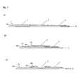
- Fig. 3a
- schematically depicts a first embodiment of the device of the present invention, having a zone of a second hardened coating (2) contiguously located between two zones of a first hardened coating (1) on a substrate (S). The first and second coatings comprise oriented pigment particles (P) in a transparent binder (M).
- Fig. 3b
- schematically depicts a second embodiment of the device of the present invention, having, on a substrate (S), a smaller area of a second hardened coating (2), comprising oriented pigment particles (P2) in a transparent binder (M2), applied over a larger area of a first hardened coating (1), comprising oriented pigment particles (P1) in a transparent binder (M1) such that said first (1) coating appears contiguously located between two zones of said second (2) coating.
- Fig 3c
- schematically depicts a third embodiment of the device of the present invention, wherein said first (1) and said second (2) hardened coatings partially overlap each other.
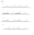
- Fig. 4
- schematically depicts a linear cross-section through a device of the present invention, having a "checkered" structure: a) a first embodiment having a plurality of first (1) and second (2) coatings contiguously located between each other on a substrate (S); b) a second embodiment having a plurality of second coatings (2) printed over a first coating (1) on a substrate (S) such that said first (1) and second (2) coatings appear contiguously located between each other; c) a third embodiment having a plurality of first coatings (1) applied to the recto side of a flat transparent substrate (S) and a plurality of second coatings (2) applied to the verso side of said flat transparent substrate (S) such that said first (1) and second (2) coatings appear contiguously located between each other; d) a fourth embodiment, similar to the embodiment of
Fig. 4c , wherein said first (1) and said second (2) coatings partially overlap each other. - Fig. 5
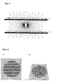
- schematically illustrates the use of a same type of magnet or magnetic field to orient magnetically orientable pigment particles in first (1) and second (2) coatings according to first and second curved surfaces, respectively: (1) application from below the substrate/coating for producing a pigment orientation imitating a negatively curved surface, and (2) application from above the substrate/coating for producing a pigment orientation imitating a positively curved surface.
- Fig. 6
- shows a photographic picture of a device according to the present invention, a) in orthogonal (left image) and b) in oblique (tilted) view (right image). Upon tilting the device, the "snail" appears to float above the plane of the background.
- Fig. 7
- schematically depicts a "fractured bar" type device according to the present invention. A zone of a second coating imitating a second curved surface is contiguously located between two zones of a first coating imitating a first curved surface. Upon tilting the device (up, down), said first and second zones appear to move in different planes in space with respect to each other.
- a) shows a zone of positive cylindrical curvature located between two zones of negative cylindrical curvature, having their apices aligned such as to form an "undulated" structure;
- b) shows a zone of negative cylindrical curvature located between two zones of positive cylindrical curvature, having their apices aligned such as to form a "channel" structure;
- c) shows a zone of positive cylindrical curvature located between two zones of negative cylindrical curvature, having their apices aligned such as to form a "channel" structure
- d) illustrates the pigment orientation in a device of the type of
Fig. 7 c) ; - e) shows a further extension of the device of the type of
Fig. 7a ).
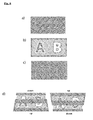
- Fig. 8
- schematically illustrates a further embodiment of the device of the present invention, wherein the first and the second coating appear in the form of indicia: a) background layer of negative curvature; b) second, overprinted layer of positive curvature (the hashed parts are printed); c) superposition of background and second layers; d) "double-rolling-bar" effect displayed by the superposition upon tilting: The bright zone of letter "A" moves with the rotational sense of tilting; the bright zone of letter "B" moves against the rotational sense of tilting.
- The present invention is further described by reference to non-limiting examples and drawings.
- A first coating (1) is applied in the form of two square zones of 100 mm2 each, printed 10 mm apart, as illustrated in
Fig. 7c , on a sheet of cotton-based paper with a silkscreen UV-drying ink containing platelet-like magnetic optically variable pigment particles as described in example 2a ofEP 2 024 451 B1coating 1 accompanied by a simultaneous upward movement of the reflection emanating from the single zone incoating 2, as the print is tilted backwards. Here tilting backwards means rotating the printed substrate about an axis located in the plane of the substrate, passing through all 3 printed zones, so that the top of the substrate moves away from the observer whilst the bottom of the substrate moves toward the observer. - A first coating (1) is applied in the form of two square zones of 100 mm2 each, printed 10 mm apart, as illustrated in
Fig. 7e , on a sheet of transparent polymer substrate with a silkscreen LTV-drying ink containing platelet-like magnetic optically variable pigment particles as described in example 3 ofEP 2 024 451 B1coating 1 is cured under UV irradiation, permanently locking the orientation of the reflective colour-shifting flakes. A second coating (2) is applied on the opposite side of the substrate relative to the first coating, to form a second set of two zones of 100 mm2 located above and below one of said first two zones, as depicted inFig. 7e , using the same ink composition. This second coating, while still wet on the substrate, is subjected to a magnetic field generated by said set of two magnets, positioned 3 mm below the surface of the substrate, on the side opposite the coating (2), thus creating positively curved reflective surfaces according to the present invention when observed from the side printed with coating (1). Once oriented, said zones reflect light in such a way that each zone visually resembles the internal surface of a hollow metallic cylinder. Said second coating (2) is cured under ultraviolet irradiation, permanently locking the orientation of the reflective flakes. When observed from the side printed with coating (1), example 2 shows a conspicuous visual effect characterized by a downward movement of the reflections emanating from the two zones in coating (1) accompanied by a simultaneous upward movement of the reflection emanating from the two zones in coating (2), as the print is tilted backwards. Here tilting backwards means rotating the printed substrate about an axis located in the plane of the substrate, passing through the center of the printed surface and perpendicular to the imaginary line connecting the center of the four printed zones, so that the top of the substrate moves away from the observer whilst the bottom of the substrate moves toward the observer. When observed from the side printed with coating (2), the apparent motion of each bright reflection is reversed. - Example three, shown in
Fig. 6 , comprises two areas printed with an ink composition containing orientable reflective flakes. A first coating (1) is applied in the form a solid circular area with a diameter of 29 mm, printed, on a sheet of cotton-based paper with a silkscreen UV-drying ink containing platelet-like magnetic optically variable pigment particles as described in example 2a ofEP 2 024 451 B1
Claims (31)
- Device comprising a substrate (S), and on said substrate (S) a plurality of jointly visible zones of first (1) and of second (2) hardened coatings comprising oriented pigment particles (P1, P2) in a transparent binder (M1, M2), said first (1) hardened coating having a pigment orientation imitating a first curved surface and said second (2) hardened coating having a pigment orientation imitating a second curved surface different from said first curved surface, characterized in that, along a linear section through the device, at least one zone of said second (2) hardened coating is contiguously located between two zones of said first (1) hardened coating.
- Device according to claim 1, wherein, along a linear section through the device, additionally at least one of said two zones of said first (1) hardened coating is contiguously located within two zones of said second (2) hardened coating.
- Device according to one of claims 1 or 2, wherein said first and said second curved surfaces are different from each other in at least one of the following properties: i) the sign of curvature, which may be positive, towards the observer, or negative, away from the observer; ii) the amount of curvature, which may be high or low; iii) the direction or axis of curvature; iv) the nature of curvature which may in particular be cylindrical, conical, elliptical, spherical or saddle-shaped.
- Device according to one of claims 1 to 3, wherein said first and said second coatings are disposed either aside each other and/or on top of each other.
- Device according to one of claims 1 to 4, wherein said substrate is selected from the group consisting of the paper substrates, the opaque or opacified polymer substrates, the transparent polymer substrates and the metallic substrates.
- Device according to one of claims 1 to 5, wherein said first (1) and said second (2) hardened coatings are disposed on the recto and on the verso side, respectively, of a transparent substrate.
- Device according to one of claims 1 to 6, comprising a combination of said first and said second coatings with at least one further coating, comprising oriented pigment particles.
- Device according to one of claims 1 to 7, wherein said first and/or said second hardened coating is present in the form of indicia selected from the group consisting of the simple geometric figures or patterns, the letters, the texts, the logos and the images.
- Device according to one of claims 1 to 8, wherein said oriented pigment particle in said first and/or said second hardened coating is a magnetic pigment particle, comprising a permanent-magnetic or a magnetizable material of the ferromagnetic or ferrimagnetic type.
- Device according to one of claims 1 to 9, wherein said oriented pigment particle in said first and/or said second hardened coating is selected from the group comprising the flake-shaped vacuum-deposited magnetic thin-film interference pigment particles.
- Device according to one of claims 1 to 10, wherein said oriented pigment particle (P) in said first and/or said second hardened coating is an optically variable magnetic pigment particle.
- Device according to one of claims 1 to 11, wherein said first and/or said second hardened coating additionally comprises at least one further color-shifting pigment selected from the group consisting of the vacuum-deposited optically variable thin-film interference pigments having an all-dielectric or a metal-dielectric interference design, the coated metal-core particles, the coated dielectric particles, the cholesteric liquid crystal polymer pigments, the embossed holographic pigments, and the mixtures thereof.
- Device according to one of claims 1 to 12, wherein said first and/or said second hardened coating additionally comprises a dye and/or at least one further, non-color-shifting pigment.
- Device according to one of claims 1 to 13, wherein the device comprises a combination of areas coated with a composition comprising optically variable pigment and areas coated with a composition not comprising optically variable pigment.
- Method for producing the device of one of claims 1 to 14, comprising the step of applying to a substrate (S) a plurality of areas of first (C1) and of second (C2) coating compositions comprising pigment particles (P1, P2) in a transparent binder (M1, M2), orienting the pigment particles (P1) in said applied first (C1) coating composition such as to imitate a first curved surface, orienting the pigment particles (P2) in said applied second (C2) coating composition such as to imitate a second curved surface different from said first curved surface, and hardening said first and said second coating compositions to obtain first and second hardened coatings (1, 2) having the oriented particles fixed in their respective positions and orientations wherein said areas of first (C1) and of second (C2) coating compositions are applied such that, along a linear section through the device, at least one zone of said second (2) hardened coating is contiguously located between two zones of said first (1) hardened coating.
- Method according to claim 15, wherein said areas of first (C1) and of second (C2) coating compositions are applied such that additionally at least one of said two zones of said first (1) hardened coating is contiguously located within two zones of said second (2) hardened coating.
- Method according to one of claims 15 to 16, wherein said first and said second curved surfaces are different from each other in at least one of the following properties: i) the sign of curvature, which may be positive, towards the observer, or negative, away from the observer; ii) the amount of curvature, which may be high or low; iii) the direction or axis of curvature; iv) the nature of curvature which may in particular be cylindrical, conical, elliptical, spherical or saddle-shaped.
- Method according to one of claims 15 to 17, wherein said substrate (S) is selected from the group consisting of the paper substrates, the opaque or opacified polymer substrates, the transparent polymer substrates and the metallic substrates.
- Method according to one of claims 15 to 18, wherein said first and said second coatings are applied by a printing process chosen from silkscreen printing, flexographic printing and gravure printing, using a corresponding coating composition.
- Method according to one of claims 15 to 19, wherein the coating composition is formulated for and hardened by radiation curing, selected from LTV-curing and electron-beam curing.
- Method according to one of claims 15 to 20, wherein said first and said second coating compositions (C1, C2) are applied to the recto and to the verso side, respectively, of a transparent substrate (S).
- Method according to one of claims 15 to 21, wherein said pigment particles (P1, P2) in said first and said second coating compositions (C1, C2) are magnetic pigment particles, comprising a permanent-magnetic or a magnetizable material of the ferromagnetic or ferrimagnetic type, and wherein said orienting the pigment particles (P1, P2) in said applied first and second coating compositions (C1, C2) is performed by applying magnetic fields.
- Method according to one of claims 15 to 22, wherein said pigment particles (P1, P2) in said first and/or said second coating compositions (C1, C2) are selected from the group comprising the flake-shaped vacuum-deposited magnetic thin-film interference pigment particles.
- Method according to one of claims 15 to 23, wherein said pigment particles (P1, P2) in said first and/or said second coating compositions (C1, C2) are optically variable magnetic pigment particles.
- Method according to one of claims 15 to 24, wherein the first hardened coating (1) is produced, i.e. applied, oriented, and hardened, subsequent to the second hardened coating (2), or vice versa.
- Method according to one of claims 15 to 25, wherein said first and said second coatings are applied either aside each other and/or on top of each other.
- Method according to one of claims 15 to 24, wherein the first hardened coating (1) and the second hardened coating (2) are produced in a single operation through the following sequence of stepsa) applying a coating composition (C), comprising magnetic or magnetizable pigment particles (P) onto a substrate (S);b) orienting said magnetic or magnetizable pigment particles (P) according to said first curved surface by applying a first magnetic field;c) selectively hardening said applied coating composition (C) in first areas (A1), hereby fixing the magnetic pigment particles (P) in their positions and orientations;d) orienting said magnetic or magnetizable pigment particles (P) in the unhardened part of the coating composition (C) according to said second curved surface by applying a second magnetic field;e) hardening said applied coating composition (C) in second areas (A2), hereby fixing the magnetic pigment particles (P) in their positions and orientations.
- Method according to one of claims 15 to 27, wherein the steps of applying, orienting, and hardening a coating composition comprising pigment particles (P) in a transparent binder (M) are repeated to produce further coatings on said substrate (S) and/or said coatings (1, 2).
- Method according to one of claims 15 to 28, wherein the magnetic pigment particles (P, P1) are oriented according to said first curved surface by applying a magnet from the bottom of the substrate, and the magnetic pigment particles (P, P2) are oriented according to said second curved surface by applying a magnet from the top of the substrate, or vice versa.
- Use of a device according to one of claims 1 to 14 for the protection of a commercial good or of a security document selected from the group consisting of the banknotes, value documents, passports, identity cards, banking cards, credit cards, access documents or cards, transportation tickets or cards, tax banderoles, and product labels
- Article selected from the commercial goods and the group of security document consisting of the banknotes, value documents, passports, identity cards, banking cards, credit cards, access documents or cards, transportation tickets or
cards, tax banderoles, and product labels, characterized in that the article carries one or more devices according to one of claims 1 to 14.
Priority Applications (24)
| Application Number | Priority Date | Filing Date | Title |
|---|---|---|---|
| RS20150145A RS53855B1 (en) | 2011-02-07 | 2011-02-07 | Device displaying a dynamic visual motion effect and method for producing same |
| EP11153523.3A EP2484455B1 (en) | 2011-02-07 | 2011-02-07 | Device displaying a dynamic visual motion effect and method for producing same |
| DK11153523T DK2484455T3 (en) | 2011-02-07 | 2011-02-07 | A device for displaying a dynamic visual movement effect and process for producing same |
| PT111535233T PT2484455E (en) | 2011-02-07 | 2011-02-07 | Device displaying a dynamic visual motion effect and method for producing same |
| ES11153523.3T ES2532531T3 (en) | 2011-02-07 | 2011-02-07 | Device that exhibits a dynamic visual movement effect and a method to produce the same |
| PL11153523T PL2484455T3 (en) | 2011-02-07 | 2011-02-07 | Device displaying a dynamic visual motion effect and method for producing same |
| MYPI2013701233A MY161330A (en) | 2011-02-04 | 2012-02-03 | Device displaying a dynamic visual motion effect and method for producing same |
| BR112013019624-6A BR112013019624B1 (en) | 2011-02-04 | 2012-02-03 | DEVICE DISPLAYING EFFECT OF DYNAMIC MOVEMENT, METHOD TO PRODUCE THE SAME, USE OF THAT DEVICE AND ARTICLE |
| AU2012213714A AU2012213714B2 (en) | 2011-02-04 | 2012-02-03 | Device displaying a dynamic visual motion effect and method for producing same |
| JP2013552139A JP6051432B2 (en) | 2011-02-04 | 2012-02-03 | Mechanism for displaying dynamic visual motion effect and method for manufacturing the same |
| ARP120100352A AR087229A1 (en) | 2011-02-04 | 2012-02-03 | DEVICE SHOWING A DYNAMIC VISUAL MOVEMENT EFFECT AND METHOD TO PRODUCE IT |
| KR1020137022355A KR101887719B1 (en) | 2011-02-04 | 2012-02-03 | Device displaying a dynamic visual motion effect and method for producing same |
| MX2013008977A MX2013008977A (en) | 2011-02-04 | 2012-02-03 | Device displaying a dynamic visual motion effect and method for producing same. |
| EA201300883A EA025147B1 (en) | 2011-02-04 | 2012-02-03 | Security element and method for producing same |
| TW101103458A TWI559986B (en) | 2011-02-04 | 2012-02-03 | Device displaying a dynamic visual motion effect and method for producing same, method of protecting a commercial good or a security document, and an article selected from commercial goods and security documents |
| MA36157A MA34888B1 (en) | 2011-02-04 | 2012-02-03 | DEVICE DISPLAYING A DYNAMIC VISUAL MOTION EFFECT AND METHOD FOR PRODUCING THE SAME |
| US13/365,846 US9199502B2 (en) | 2011-02-04 | 2012-02-03 | Security element displaying a visual motion effect and method for producing same |
| PCT/EP2012/000488 WO2012104098A1 (en) | 2011-02-04 | 2012-02-03 | Device displaying a dynamic visual motion effect and method for producing same |
| CA2825899A CA2825899C (en) | 2011-02-04 | 2012-02-03 | Device displaying a dynamic visual motion effect and method for producing same |
| CN201280007103.XA CN103338871B (en) | 2011-02-04 | 2012-02-03 | For showing device and the manufacture method thereof of dynamic vision movement effects |
| CL2013002225A CL2013002225A1 (en) | 2011-02-04 | 2013-08-02 | Device comprising a sutrate with a plurality of zones with a first and a second hardened coating comprising pigment particles with different orientation, where at least one area of said second coating is located adjacently between two zones of said first hardened coating. |
| ZA2013/06578A ZA201306578B (en) | 2011-02-04 | 2013-09-02 | Device displaying a dynamic visual motion effect and method for producing same |
| CO13208724A CO6761333A2 (en) | 2011-02-04 | 2013-09-03 | Device that exhibits a dynamic visual movement effect and a method to produce the same |
| HK13112826.0A HK1185305A1 (en) | 2011-02-04 | 2013-11-15 | Device displaying a dynamic visual motion effect and method for producing same |
Applications Claiming Priority (1)
| Application Number | Priority Date | Filing Date | Title |
|---|---|---|---|
| EP11153523.3A EP2484455B1 (en) | 2011-02-07 | 2011-02-07 | Device displaying a dynamic visual motion effect and method for producing same |
Publications (2)
| Publication Number | Publication Date |
|---|---|
| EP2484455A1 true EP2484455A1 (en) | 2012-08-08 |
| EP2484455B1 EP2484455B1 (en) | 2014-12-24 |
Family
ID=43970452
Family Applications (1)
| Application Number | Title | Priority Date | Filing Date |
|---|---|---|---|
| EP11153523.3A Active EP2484455B1 (en) | 2011-02-04 | 2011-02-07 | Device displaying a dynamic visual motion effect and method for producing same |
Country Status (21)
| Country | Link |
|---|---|
| US (1) | US9199502B2 (en) |
| EP (1) | EP2484455B1 (en) |
| JP (1) | JP6051432B2 (en) |
| KR (1) | KR101887719B1 (en) |
| CN (1) | CN103338871B (en) |
| AR (1) | AR087229A1 (en) |
| AU (1) | AU2012213714B2 (en) |
| BR (1) | BR112013019624B1 (en) |
| CA (1) | CA2825899C (en) |
| CO (1) | CO6761333A2 (en) |
| DK (1) | DK2484455T3 (en) |
| EA (1) | EA025147B1 (en) |
| ES (1) | ES2532531T3 (en) |
| MA (1) | MA34888B1 (en) |
| MX (1) | MX2013008977A (en) |
| MY (1) | MY161330A (en) |
| PL (1) | PL2484455T3 (en) |
| PT (1) | PT2484455E (en) |
| RS (1) | RS53855B1 (en) |
| TW (1) | TWI559986B (en) |
| WO (1) | WO2012104098A1 (en) |
Cited By (15)
| Publication number | Priority date | Publication date | Assignee | Title |
|---|---|---|---|---|
| WO2014006416A2 (en) * | 2012-07-06 | 2014-01-09 | De La Rue International Limited | Security devices |
| EP2944381A3 (en) * | 2014-05-12 | 2016-01-20 | Viavi Solutions Inc. | Optically variable device comprising magnetic flakes |
| EP2868483B1 (en) | 2013-10-30 | 2016-07-20 | Giesecke & Devrient GmbH | Method for making a security element |
| WO2016193252A1 (en) * | 2015-06-02 | 2016-12-08 | Sicpa Holding Sa | Processes for producing optical effects layers |
| KR20170037897A (en) * | 2014-07-30 | 2017-04-05 | 시크파 홀딩 에스에이 | Belt-driven processes for producing optical effect layers |
| EP3007832B1 (en) * | 2013-06-14 | 2019-03-06 | Sicpa Holding Sa | Permanent magnet assemblies for generating concave field lines and process for creating optical effect coating therewith (inverse rolling bar) |
| CN110143076A (en) * | 2019-05-28 | 2019-08-20 | 成都印钞有限公司 | A kind of magnetic optically ink determines magnetism method |
| WO2019233625A1 (en) * | 2018-06-05 | 2019-12-12 | Giesecke+Devrient Currency Technology Gmbh | Effect pigment, printing ink, security element, data carrier and production method |
| DE102018127936A1 (en) * | 2018-11-08 | 2020-05-14 | Koenig & Bauer Ag | Device, printing machine and method for producing a security element on a substrate |
| WO2020148076A1 (en) * | 2019-01-15 | 2020-07-23 | Sicpa Holding Sa | Process for producing optical effect layers |
| WO2021259527A1 (en) * | 2020-06-23 | 2021-12-30 | Sicpa Holding Sa | Methods for producing optical effect layers comprising magnetic or magnetizable pigment particles |
| CN114728537A (en) * | 2019-11-27 | 2022-07-08 | 捷德货币技术有限责任公司 | Effect pigments, method for the production thereof, valuable documents and printing inks |
| EP3459758B1 (en) | 2017-09-22 | 2022-11-09 | Giesecke+Devrient Currency Technology GmbH | Method for producing a valuable document and printing device |
| RU2798616C2 (en) * | 2019-01-15 | 2023-06-23 | Сикпа Холдинг Са | Method for obtaining layers with optical effect |
| WO2023161464A1 (en) * | 2022-02-28 | 2023-08-31 | Sicpa Holding Sa | Methods for producing optical effect layers comprising magnetic or magnetizable pigment particles and exhibiting one or more indicia |
Families Citing this family (37)
| Publication number | Priority date | Publication date | Assignee | Title |
|---|---|---|---|---|
| AR094362A1 (en) * | 2013-01-09 | 2015-07-29 | Sicpa Holding Sa | LAYERS OF OPTICAL EFFECTS THAT SHOW AN OPTICAL EFFECT THAT DEPENDS ON THE VISION ANGLE; PROCESSES AND DEVICES FOR THE PRODUCTION OF THESE LAYERS, ITEMS THAT HAVE A LAYER OF OPTICAL EFFECTS AND USES OF THESE LAYERS |
| WO2014177375A1 (en) | 2013-05-01 | 2014-11-06 | Sicpa Holding Sa | Security elements exhibiting a dynamic visual motion |
| KR20160002943A (en) | 2013-05-02 | 2016-01-08 | 시크파 홀딩 에스에이 | Processes for producing security threads or stripes |
| TWI641660B (en) | 2013-08-05 | 2018-11-21 | 瑞士商西克帕控股有限公司 | Magnetic or magnetisable pigment particles and optical effect layers |
| RU2641864C2 (en) | 2013-12-11 | 2018-01-22 | Сикпа Холдинг Са | Optically variable security threads and strips |
| ES2755149T3 (en) | 2013-12-13 | 2020-04-21 | Sicpa Holding Sa | Processes to produce effect layers |
| EP3105064B1 (en) * | 2014-02-13 | 2017-09-13 | Sicpa Holding SA | Security threads and stripes |
| PT2965920T (en) | 2014-07-09 | 2018-01-16 | Sicpa Holding Sa | Optically variable magnetic security threads and stripes |
| TW201605655A (en) * | 2014-07-29 | 2016-02-16 | 西克帕控股有限公司 | Processes for in-field hardening of optical effect layers produced by magnetic-field generating devices generating concave field lines |
| CN104260572B (en) * | 2014-09-26 | 2016-11-23 | 惠州市华阳光学技术有限公司 | A kind of magnetic orientation pattern and preparation method thereof |
| JP6620340B2 (en) * | 2014-11-27 | 2019-12-18 | シクパ ホルディング ソシエテ アノニムSicpa Holding Sa | Device and method for orienting platelet-shaped magnetic or magnetizable pigment particles |
| DE102015005911A1 (en) * | 2015-05-07 | 2016-11-10 | Giesecke & Devrient Gmbh | Optically variable security element |
| DE102015005969A1 (en) * | 2015-05-08 | 2016-11-10 | Giesecke & Devrient Gmbh | Optically variable security element |
| CN106650872A (en) * | 2015-10-30 | 2017-05-10 | 北京柯斯元科技有限公司 | An anti-counterfeiting mark, an anti-counterfeiting system, texture particles for the anti-counterfeiting mark and a use method for the anti-counterfeiting mark |
| EP3502755A4 (en) * | 2016-08-19 | 2020-06-10 | Zeon Corporation | Display medium for assessment and method for manufacturing same |
| RU2754983C2 (en) * | 2016-08-31 | 2021-09-08 | Виави Солюшнз Инк. | Product with inclined reflective segments |
| US10357991B2 (en) * | 2016-12-19 | 2019-07-23 | Viavi Solutions Inc. | Security ink based security feature |
| JP2019080055A (en) * | 2017-10-20 | 2019-05-23 | キヤノン株式会社 | Composite magnetic material, magnet, motor, and method of producing composite magnetic material |
| CN109917626B (en) * | 2017-12-12 | 2022-04-05 | 株式会社爱睦悉缇 | Pattern forming method using magnetic ink and magnetic force and jig therefor |
| TWI772576B (en) | 2018-01-17 | 2022-08-01 | 瑞士商西克帕控股有限公司 | Processes for producing optical effects layers |
| US10642214B2 (en) * | 2018-08-13 | 2020-05-05 | Viavi Solutions Inc. | Optical security device based on a surface of revolution |
| TWI829734B (en) * | 2018-09-10 | 2024-01-21 | 瑞士商西克帕控股有限公司 | Optical effect layers, processes for producing the same, and security documents, decorative elements, and objects comprising the same |
| SG11202109245YA (en) | 2019-02-28 | 2021-09-29 | Sicpa Holding Sa | Verifiable access credential |
| TW202100960A (en) | 2019-02-28 | 2021-01-01 | 瑞士商西克帕控股有限公司 | Method for authenticating a magnetically induced mark with a portable device |
| CN111776471B (en) * | 2019-08-16 | 2022-07-12 | 西安印钞有限公司 | Scene change anti-counterfeiting structure, anti-counterfeiting plastic package and preparation method |
| WO2021072105A1 (en) * | 2019-10-08 | 2021-04-15 | Viavi Solutions Inc. | Security pigment and optical security element |
| BR112022023694A2 (en) | 2020-05-26 | 2022-12-20 | Sicpa Holding Sa | MAGNETIC ASSEMBLIES AND METHODS FOR PRODUCING OPTICAL EFFECT LAYERS COMPRISING ORIENTED PLATELET-FORMED MAGNETIC OR MAGNETIZABLE PIGMENT PARTICLES |
| AR123351A1 (en) | 2020-09-02 | 2022-11-23 | Sicpa Holding Sa | SECURITY DOCUMENTS OR ARTICLES INCLUDING OPTICAL EFFECT COATINGS COMPRISING MAGNETIC OR MAGNETIZABLE PIGMENT PARTICLES AND METHODS FOR PRODUCING SUCH OPTICAL EFFECT LAYERS |
| CN112712995A (en) * | 2020-12-18 | 2021-04-27 | 成都佳驰电子科技有限公司 | Preparation method of high-orientation magnetic wave-absorbing film |
| CN112672626A (en) * | 2020-12-18 | 2021-04-16 | 成都佳驰电子科技有限公司 | Multi-band magnetic wave-absorbing film and preparation method thereof |
| CN112644200A (en) * | 2021-01-05 | 2021-04-13 | 彭亮 | Phase-change optical anti-counterfeiting element |
| TW202239482A (en) | 2021-03-31 | 2022-10-16 | 瑞士商西克帕控股有限公司 | Methods for producing optical effect layers comprising magnetic or magnetizable pigment particles and exhibiting one or more indicia |
| CA3221708A1 (en) * | 2021-06-11 | 2022-12-15 | Evgeny LOGINOV | Optical effect layers comprising magnetic or magnetizable pigment particles and methods for producing said optical effect layers |
| CN113547834B (en) * | 2021-07-14 | 2023-04-07 | 中钞印制技术研究院有限公司 | Multi-color light-variable printing device and printing method thereof |
| CN114633574A (en) * | 2022-03-24 | 2022-06-17 | 彭亮 | Safety line or strip with dynamic visual three-dimensional effect |
| WO2024028408A1 (en) | 2022-08-05 | 2024-02-08 | Sicpa Holding Sa | Methods for producing optical effect layers comprising magnetic or magnetizable pigment particles and exhibiting one or more indicia |
| EP4338854A2 (en) | 2023-12-20 | 2024-03-20 | Sicpa Holding SA | Processes for producing optical effects layers |
Citations (12)
| Publication number | Priority date | Publication date | Assignee | Title |
|---|---|---|---|---|
| US4838648A (en) | 1988-05-03 | 1989-06-13 | Optical Coating Laboratory, Inc. | Thin film structure having magnetic and color shifting properties |
| EP0428933A2 (en) * | 1989-11-16 | 1991-05-29 | MERCK PATENT GmbH | Materials coated with plate like pigmets |
| WO2002073250A2 (en) | 2001-03-09 | 2002-09-19 | Sicpa Holding S.A. | Magnetic thin film interference device or pigment and method of making it, printing ink or coating composition, security document and use of such a magnetic thin film interference device |
| WO2004007095A2 (en) | 2002-07-15 | 2004-01-22 | Jds Uniphase Corporation | Method and apparatus for orienting magnetic flakes and image obtained by said method |
| WO2004024836A2 (en) * | 2002-09-13 | 2004-03-25 | Jds Uniphase Corporation | Alignable diffractive pigment flakes |
| WO2005002866A1 (en) | 2003-07-03 | 2005-01-13 | Sicpa Holding S.A. | Method and means for producing a magnetically induced design in a coating containing magnetic particles |
| US20050106367A1 (en) | 2002-07-15 | 2005-05-19 | Jds Uniphase Corporation | Method and apparatus for orienting magnetic flakes |
| EP1710756A1 (en) * | 2005-04-06 | 2006-10-11 | JDS Uniphase Corporation | Dynamic appearance-changing optical devices (DACOD) printed in a shaped magnetic field including printable fresnel structures |
| WO2007131833A1 (en) | 2006-05-12 | 2007-11-22 | Sicpa Holding S.A. | Coating composition for producing magnetically induced images |
| WO2008009569A2 (en) | 2006-07-19 | 2008-01-24 | Sicpa Holding S.A. | Oriented image coating on transparent substrate |
| WO2008046702A1 (en) | 2006-10-17 | 2008-04-24 | Sicpa Holding S.A. | Method and means for producing a magnetically induced indicia in a coating containing magnetic particles |
| US7738175B2 (en) | 2003-11-21 | 2010-06-15 | Visual Physics, Llc | Micro-optic security and image presentation system providing modulated appearance of an in-plane image |
Family Cites Families (7)
| Publication number | Priority date | Publication date | Assignee | Title |
|---|---|---|---|---|
| KR910009851B1 (en) * | 1989-04-22 | 1991-11-30 | 삼성전자 주식회사 | Double recording preventing circuit of laser disk driving device |
| JPH07232492A (en) * | 1994-02-24 | 1995-09-05 | Nok Corp | Magnetic visible card |
| JPH11302613A (en) * | 1998-04-27 | 1999-11-02 | Nippon Paint Co Ltd | Decorative pressure-sensitive adhesive film and its production |
| US7604855B2 (en) * | 2002-07-15 | 2009-10-20 | Jds Uniphase Corporation | Kinematic images formed by orienting alignable flakes |
| US6808806B2 (en) * | 2001-05-07 | 2004-10-26 | Flex Products, Inc. | Methods for producing imaged coated articles by using magnetic pigments |
| US7674501B2 (en) * | 2002-09-13 | 2010-03-09 | Jds Uniphase Corporation | Two-step method of coating an article for security printing by application of electric or magnetic field |
| DK1745940T3 (en) * | 2005-07-20 | 2014-03-03 | Jds Uniphase Corp | Two-step FOR COATING OF AN OBJECT OF SAFETY PRESSURE |
-
2011
- 2011-02-07 EP EP11153523.3A patent/EP2484455B1/en active Active
- 2011-02-07 ES ES11153523.3T patent/ES2532531T3/en active Active
- 2011-02-07 RS RS20150145A patent/RS53855B1/en unknown
- 2011-02-07 DK DK11153523T patent/DK2484455T3/en active
- 2011-02-07 PT PT111535233T patent/PT2484455E/en unknown
- 2011-02-07 PL PL11153523T patent/PL2484455T3/en unknown
-
2012
- 2012-02-03 BR BR112013019624-6A patent/BR112013019624B1/en active IP Right Grant
- 2012-02-03 AR ARP120100352A patent/AR087229A1/en not_active Application Discontinuation
- 2012-02-03 WO PCT/EP2012/000488 patent/WO2012104098A1/en active Application Filing
- 2012-02-03 JP JP2013552139A patent/JP6051432B2/en active Active
- 2012-02-03 KR KR1020137022355A patent/KR101887719B1/en active IP Right Grant
- 2012-02-03 TW TW101103458A patent/TWI559986B/en not_active IP Right Cessation
- 2012-02-03 CA CA2825899A patent/CA2825899C/en active Active
- 2012-02-03 US US13/365,846 patent/US9199502B2/en active Active
- 2012-02-03 MA MA36157A patent/MA34888B1/en unknown
- 2012-02-03 CN CN201280007103.XA patent/CN103338871B/en active Active
- 2012-02-03 EA EA201300883A patent/EA025147B1/en not_active IP Right Cessation
- 2012-02-03 MX MX2013008977A patent/MX2013008977A/en unknown
- 2012-02-03 MY MYPI2013701233A patent/MY161330A/en unknown
- 2012-02-03 AU AU2012213714A patent/AU2012213714B2/en active Active
-
2013
- 2013-09-03 CO CO13208724A patent/CO6761333A2/en unknown
Patent Citations (14)
| Publication number | Priority date | Publication date | Assignee | Title |
|---|---|---|---|---|
| US4838648A (en) | 1988-05-03 | 1989-06-13 | Optical Coating Laboratory, Inc. | Thin film structure having magnetic and color shifting properties |
| EP0428933A2 (en) * | 1989-11-16 | 1991-05-29 | MERCK PATENT GmbH | Materials coated with plate like pigmets |
| WO2002073250A2 (en) | 2001-03-09 | 2002-09-19 | Sicpa Holding S.A. | Magnetic thin film interference device or pigment and method of making it, printing ink or coating composition, security document and use of such a magnetic thin film interference device |
| US20050106367A1 (en) | 2002-07-15 | 2005-05-19 | Jds Uniphase Corporation | Method and apparatus for orienting magnetic flakes |
| WO2004007095A2 (en) | 2002-07-15 | 2004-01-22 | Jds Uniphase Corporation | Method and apparatus for orienting magnetic flakes and image obtained by said method |
| US20040051297A1 (en) | 2002-07-15 | 2004-03-18 | Flex Products, Inc., A Jds Uniphase Company | Method and apparatus for orienting magnetic flakes |
| WO2004024836A2 (en) * | 2002-09-13 | 2004-03-25 | Jds Uniphase Corporation | Alignable diffractive pigment flakes |
| WO2005002866A1 (en) | 2003-07-03 | 2005-01-13 | Sicpa Holding S.A. | Method and means for producing a magnetically induced design in a coating containing magnetic particles |
| US7738175B2 (en) | 2003-11-21 | 2010-06-15 | Visual Physics, Llc | Micro-optic security and image presentation system providing modulated appearance of an in-plane image |
| EP1710756A1 (en) * | 2005-04-06 | 2006-10-11 | JDS Uniphase Corporation | Dynamic appearance-changing optical devices (DACOD) printed in a shaped magnetic field including printable fresnel structures |
| WO2007131833A1 (en) | 2006-05-12 | 2007-11-22 | Sicpa Holding S.A. | Coating composition for producing magnetically induced images |
| EP2024451B1 (en) | 2006-05-12 | 2009-09-30 | Sicpa Holding S.A. | Coating composition for producing magnetically induced images |
| WO2008009569A2 (en) | 2006-07-19 | 2008-01-24 | Sicpa Holding S.A. | Oriented image coating on transparent substrate |
| WO2008046702A1 (en) | 2006-10-17 | 2008-04-24 | Sicpa Holding S.A. | Method and means for producing a magnetically induced indicia in a coating containing magnetic particles |
Cited By (26)
| Publication number | Priority date | Publication date | Assignee | Title |
|---|---|---|---|---|
| WO2014006416A3 (en) * | 2012-07-06 | 2014-03-06 | De La Rue International Limited | Security devices |
| WO2014006416A2 (en) * | 2012-07-06 | 2014-01-09 | De La Rue International Limited | Security devices |
| US10543710B2 (en) | 2012-07-06 | 2020-01-28 | De La Rue International Limited | Security devices |
| US9902186B2 (en) | 2012-07-06 | 2018-02-27 | De La Rue International Limited | Security devices |
| EP3007832B1 (en) * | 2013-06-14 | 2019-03-06 | Sicpa Holding Sa | Permanent magnet assemblies for generating concave field lines and process for creating optical effect coating therewith (inverse rolling bar) |
| EP2868483B1 (en) | 2013-10-30 | 2016-07-20 | Giesecke & Devrient GmbH | Method for making a security element |
| EP2944381A3 (en) * | 2014-05-12 | 2016-01-20 | Viavi Solutions Inc. | Optically variable device comprising magnetic flakes |
| KR20170037897A (en) * | 2014-07-30 | 2017-04-05 | 시크파 홀딩 에스에이 | Belt-driven processes for producing optical effect layers |
| CN107710075A (en) * | 2015-06-02 | 2018-02-16 | 锡克拜控股有限公司 | The manufacture method of optical effect layer |
| US10328739B2 (en) | 2015-06-02 | 2019-06-25 | Sicpa Holding Sa | Processes for producing optical effects layers |
| CN107710075B (en) * | 2015-06-02 | 2019-11-08 | 锡克拜控股有限公司 | The manufacturing method of optical effect layer |
| WO2016193252A1 (en) * | 2015-06-02 | 2016-12-08 | Sicpa Holding Sa | Processes for producing optical effects layers |
| EP3459758B1 (en) | 2017-09-22 | 2022-11-09 | Giesecke+Devrient Currency Technology GmbH | Method for producing a valuable document and printing device |
| WO2019233625A1 (en) * | 2018-06-05 | 2019-12-12 | Giesecke+Devrient Currency Technology Gmbh | Effect pigment, printing ink, security element, data carrier and production method |
| DE102018127936A1 (en) * | 2018-11-08 | 2020-05-14 | Koenig & Bauer Ag | Device, printing machine and method for producing a security element on a substrate |
| WO2020094291A1 (en) | 2018-11-08 | 2020-05-14 | Koenig & Bauer Ag | Device, printing machine, and method for producing a security element on a substrate |
| US11214052B2 (en) | 2018-11-08 | 2022-01-04 | Koenig & Bauer Ag | Device and printing press for producing a security element on a substrate |
| WO2020148076A1 (en) * | 2019-01-15 | 2020-07-23 | Sicpa Holding Sa | Process for producing optical effect layers |
| RU2798616C2 (en) * | 2019-01-15 | 2023-06-23 | Сикпа Холдинг Са | Method for obtaining layers with optical effect |
| CN110143076A (en) * | 2019-05-28 | 2019-08-20 | 成都印钞有限公司 | A kind of magnetic optically ink determines magnetism method |
| CN114728537A (en) * | 2019-11-27 | 2022-07-08 | 捷德货币技术有限责任公司 | Effect pigments, method for the production thereof, valuable documents and printing inks |
| CN114728537B (en) * | 2019-11-27 | 2023-10-31 | 捷德货币技术有限责任公司 | Effect pigment, method for producing the same, value document and printing ink |
| WO2021259527A1 (en) * | 2020-06-23 | 2021-12-30 | Sicpa Holding Sa | Methods for producing optical effect layers comprising magnetic or magnetizable pigment particles |
| CN115768566A (en) * | 2020-06-23 | 2023-03-07 | 锡克拜控股有限公司 | Method for producing an optical effect layer comprising magnetic or magnetizable pigment particles |
| CN115768566B (en) * | 2020-06-23 | 2024-04-12 | 锡克拜控股有限公司 | Method for producing an optical effect layer containing magnetic or magnetizable pigment particles |
| WO2023161464A1 (en) * | 2022-02-28 | 2023-08-31 | Sicpa Holding Sa | Methods for producing optical effect layers comprising magnetic or magnetizable pigment particles and exhibiting one or more indicia |
Also Published As
| Publication number | Publication date |
|---|---|
| CN103338871B (en) | 2016-04-06 |
| US20120205905A1 (en) | 2012-08-16 |
| DK2484455T3 (en) | 2015-03-09 |
| AR087229A1 (en) | 2014-03-12 |
| KR20140020870A (en) | 2014-02-19 |
| PT2484455E (en) | 2015-03-18 |
| EA025147B1 (en) | 2016-11-30 |
| MA34888B1 (en) | 2014-02-01 |
| BR112013019624B1 (en) | 2021-03-23 |
| WO2012104098A1 (en) | 2012-08-09 |
| CA2825899A1 (en) | 2012-08-09 |
| RS53855B1 (en) | 2015-08-31 |
| PL2484455T3 (en) | 2015-05-29 |
| EP2484455B1 (en) | 2014-12-24 |
| ES2532531T3 (en) | 2015-03-27 |
| JP2014510651A (en) | 2014-05-01 |
| MY161330A (en) | 2017-04-14 |
| KR101887719B1 (en) | 2018-08-10 |
| EA201300883A1 (en) | 2013-12-30 |
| US9199502B2 (en) | 2015-12-01 |
| CN103338871A (en) | 2013-10-02 |
| AU2012213714B2 (en) | 2016-04-21 |
| BR112013019624A2 (en) | 2020-11-10 |
| MX2013008977A (en) | 2013-11-01 |
| TWI559986B (en) | 2016-12-01 |
| JP6051432B2 (en) | 2016-12-27 |
| AU2012213714A1 (en) | 2013-08-01 |
| CA2825899C (en) | 2019-03-12 |
| CO6761333A2 (en) | 2013-09-30 |
| TW201236769A (en) | 2012-09-16 |
Similar Documents
| Publication | Publication Date | Title |
|---|---|---|
| EP2484455B1 (en) | Device displaying a dynamic visual motion effect and method for producing same | |
| US11504990B2 (en) | Security device formed by printing with special effect inks | |
| AU2011210194B2 (en) | Security elements and methods and apparatus for their manufacture | |
| EP1674282B1 (en) | Kinematic images formed by orienting alignable pigment flakes | |
| KR102242089B1 (en) | Articles with angled reflective segments | |
| TW202249273A (en) | Magnetic assemblies and methods for producing optical effect layers comprising oriented platelet-shaped magnetic or magnetizable pigment particles | |
| OA17623A (en) | Device displaying a dynamic visual motion effect and method for producing same. | |
| AU2015200595B2 (en) | Security elements and methods and apparatus for their manufacture | |
| UA111189C2 (en) | THE DEVICE FOR CREATING THE DYNAMIC EFFECT OF VISUAL MOVEMENT AND THE METHOD OF MANUFACTURING THIS |
Legal Events
| Date | Code | Title | Description |
|---|---|---|---|
| PUAI | Public reference made under article 153(3) epc to a published international application that has entered the european phase |
Free format text: ORIGINAL CODE: 0009012 |
|
| 17P | Request for examination filed |
Effective date: 20110207 |
|
| AK | Designated contracting states |
Kind code of ref document: A1 Designated state(s): AL AT BE BG CH CY CZ DE DK EE ES FI FR GB GR HR HU IE IS IT LI LT LU LV MC MK MT NL NO PL PT RO RS SE SI SK SM TR |
|
| AX | Request for extension of the european patent |
Extension state: BA ME |
|
| 17Q | First examination report despatched |
Effective date: 20130816 |
|
| REG | Reference to a national code |
Ref country code: DE Ref legal event code: R079 Ref document number: 602011012456 Country of ref document: DE Free format text: PREVIOUS MAIN CLASS: B05D0003140000 Ipc: B42D0015000000 |
|
| GRAP | Despatch of communication of intention to grant a patent |
Free format text: ORIGINAL CODE: EPIDOSNIGR1 |
|
| RIC1 | Information provided on ipc code assigned before grant |
Ipc: B42D 15/00 20060101AFI20140709BHEP Ipc: B41M 3/14 20060101ALI20140709BHEP Ipc: B42D 25/00 20140101ALI20140709BHEP Ipc: B05D 3/14 20060101ALI20140709BHEP |
|
| INTG | Intention to grant announced |
Effective date: 20140729 |
|
| GRAS | Grant fee paid |
Free format text: ORIGINAL CODE: EPIDOSNIGR3 |
|
| GRAA | (expected) grant |
Free format text: ORIGINAL CODE: 0009210 |
|
| AK | Designated contracting states |
Kind code of ref document: B1 Designated state(s): AL AT BE BG CH CY CZ DE DK EE ES FI FR GB GR HR HU IE IS IT LI LT LU LV MC MK MT NL NO PL PT RO RS SE SI SK SM TR |
|
| REG | Reference to a national code |
Ref country code: GB Ref legal event code: FG4D |
|
| REG | Reference to a national code |
Ref country code: CH Ref legal event code: EP |
|
| REG | Reference to a national code |
Ref country code: IE Ref legal event code: FG4D |
|
| REG | Reference to a national code |
Ref country code: AT Ref legal event code: REF Ref document number: 702933 Country of ref document: AT Kind code of ref document: T Effective date: 20150115 |
|
| REG | Reference to a national code |
Ref country code: DE Ref legal event code: R096 Ref document number: 602011012456 Country of ref document: DE Effective date: 20150219 |
|
| REG | Reference to a national code |
Ref country code: RO Ref legal event code: EPE |
|
| REG | Reference to a national code |
Ref country code: DK Ref legal event code: T3 Effective date: 20150306 |
|
| REG | Reference to a national code |
Ref country code: NL Ref legal event code: T3 Ref country code: PT Ref legal event code: SC4A Free format text: AVAILABILITY OF NATIONAL TRANSLATION Effective date: 20150309 |
|
| REG | Reference to a national code |
Ref country code: SE Ref legal event code: TRGR |
|
| REG | Reference to a national code |
Ref country code: ES Ref legal event code: FG2A Ref document number: 2532531 Country of ref document: ES Kind code of ref document: T3 Effective date: 20150327 |
|
| PG25 | Lapsed in a contracting state [announced via postgrant information from national office to epo] |
Ref country code: FI Free format text: LAPSE BECAUSE OF FAILURE TO SUBMIT A TRANSLATION OF THE DESCRIPTION OR TO PAY THE FEE WITHIN THE PRESCRIBED TIME-LIMIT Effective date: 20141224 Ref country code: LT Free format text: LAPSE BECAUSE OF FAILURE TO SUBMIT A TRANSLATION OF THE DESCRIPTION OR TO PAY THE FEE WITHIN THE PRESCRIBED TIME-LIMIT Effective date: 20141224 |
|
| REG | Reference to a national code |
Ref country code: NO Ref legal event code: T2 Effective date: 20141224 |
|
| REG | Reference to a national code |
Ref country code: LT Ref legal event code: MG4D |
|
| REG | Reference to a national code |
Ref country code: GR Ref legal event code: EP Ref document number: 20150400533 Country of ref document: GR Effective date: 20150421 |
|
| PG25 | Lapsed in a contracting state [announced via postgrant information from national office to epo] |
Ref country code: LV Free format text: LAPSE BECAUSE OF FAILURE TO SUBMIT A TRANSLATION OF THE DESCRIPTION OR TO PAY THE FEE WITHIN THE PRESCRIBED TIME-LIMIT Effective date: 20141224 Ref country code: HR Free format text: LAPSE BECAUSE OF FAILURE TO SUBMIT A TRANSLATION OF THE DESCRIPTION OR TO PAY THE FEE WITHIN THE PRESCRIBED TIME-LIMIT Effective date: 20141224 |
|
| REG | Reference to a national code |
Ref country code: PL Ref legal event code: T3 |
|
| PG25 | Lapsed in a contracting state [announced via postgrant information from national office to epo] |
Ref country code: SK Free format text: LAPSE BECAUSE OF FAILURE TO SUBMIT A TRANSLATION OF THE DESCRIPTION OR TO PAY THE FEE WITHIN THE PRESCRIBED TIME-LIMIT Effective date: 20141224 Ref country code: EE Free format text: LAPSE BECAUSE OF FAILURE TO SUBMIT A TRANSLATION OF THE DESCRIPTION OR TO PAY THE FEE WITHIN THE PRESCRIBED TIME-LIMIT Effective date: 20141224 |
|
| REG | Reference to a national code |
Ref country code: HU Ref legal event code: AG4A Ref document number: E023861 Country of ref document: HU |
|
| PG25 | Lapsed in a contracting state [announced via postgrant information from national office to epo] |
Ref country code: IS Free format text: LAPSE BECAUSE OF FAILURE TO SUBMIT A TRANSLATION OF THE DESCRIPTION OR TO PAY THE FEE WITHIN THE PRESCRIBED TIME-LIMIT Effective date: 20150424 |
|
| REG | Reference to a national code |
Ref country code: DE Ref legal event code: R097 Ref document number: 602011012456 Country of ref document: DE |
|
| PG25 | Lapsed in a contracting state [announced via postgrant information from national office to epo] |
Ref country code: LU Free format text: LAPSE BECAUSE OF FAILURE TO SUBMIT A TRANSLATION OF THE DESCRIPTION OR TO PAY THE FEE WITHIN THE PRESCRIBED TIME-LIMIT Effective date: 20150207 |
|
| PG25 | Lapsed in a contracting state [announced via postgrant information from national office to epo] |
Ref country code: MC Free format text: LAPSE BECAUSE OF FAILURE TO SUBMIT A TRANSLATION OF THE DESCRIPTION OR TO PAY THE FEE WITHIN THE PRESCRIBED TIME-LIMIT Effective date: 20141224 |
|
| PLBE | No opposition filed within time limit |
Free format text: ORIGINAL CODE: 0009261 |
|
| STAA | Information on the status of an ep patent application or granted ep patent |
Free format text: STATUS: NO OPPOSITION FILED WITHIN TIME LIMIT |
|
| 26N | No opposition filed |
Effective date: 20150925 |
|
| REG | Reference to a national code |
Ref country code: FR Ref legal event code: PLFP Year of fee payment: 6 |
|
| PG25 | Lapsed in a contracting state [announced via postgrant information from national office to epo] |
Ref country code: SI Free format text: LAPSE BECAUSE OF FAILURE TO SUBMIT A TRANSLATION OF THE DESCRIPTION OR TO PAY THE FEE WITHIN THE PRESCRIBED TIME-LIMIT Effective date: 20141224 |
|
| REG | Reference to a national code |
Ref country code: AT Ref legal event code: UEP Ref document number: 702933 Country of ref document: AT Kind code of ref document: T Effective date: 20141224 |
|
| REG | Reference to a national code |
Ref country code: FR Ref legal event code: PLFP Year of fee payment: 7 |
|
| PGFP | Annual fee paid to national office [announced via postgrant information from national office to epo] |
Ref country code: NL Payment date: 20170123 Year of fee payment: 7 |
|
| PGFP | Annual fee paid to national office [announced via postgrant information from national office to epo] |
Ref country code: NO Payment date: 20170124 Year of fee payment: 7 Ref country code: RO Payment date: 20170201 Year of fee payment: 7 |
|
| PG25 | Lapsed in a contracting state [announced via postgrant information from national office to epo] |
Ref country code: SM Free format text: LAPSE BECAUSE OF FAILURE TO SUBMIT A TRANSLATION OF THE DESCRIPTION OR TO PAY THE FEE WITHIN THE PRESCRIBED TIME-LIMIT Effective date: 20141224 |
|
| PGFP | Annual fee paid to national office [announced via postgrant information from national office to epo] |
Ref country code: BE Payment date: 20170119 Year of fee payment: 7 Ref country code: CZ Payment date: 20170125 Year of fee payment: 7 Ref country code: IE Payment date: 20170123 Year of fee payment: 7 Ref country code: DK Payment date: 20170120 Year of fee payment: 7 Ref country code: BG Payment date: 20170120 Year of fee payment: 7 Ref country code: HU Payment date: 20170131 Year of fee payment: 7 Ref country code: PT Payment date: 20170201 Year of fee payment: 7 Ref country code: PL Payment date: 20170123 Year of fee payment: 7 Ref country code: RS Payment date: 20170124 Year of fee payment: 7 |
|
| PG25 | Lapsed in a contracting state [announced via postgrant information from national office to epo] |
Ref country code: CY Free format text: LAPSE BECAUSE OF FAILURE TO SUBMIT A TRANSLATION OF THE DESCRIPTION OR TO PAY THE FEE WITHIN THE PRESCRIBED TIME-LIMIT Effective date: 20141224 |
|
| REG | Reference to a national code |
Ref country code: FR Ref legal event code: PLFP Year of fee payment: 8 |
|
| PG25 | Lapsed in a contracting state [announced via postgrant information from national office to epo] |
Ref country code: MK Free format text: LAPSE BECAUSE OF FAILURE TO SUBMIT A TRANSLATION OF THE DESCRIPTION OR TO PAY THE FEE WITHIN THE PRESCRIBED TIME-LIMIT Effective date: 20141224 |
|
| REG | Reference to a national code |
Ref country code: DK Ref legal event code: EBP Effective date: 20180228 Ref country code: NO Ref legal event code: MMEP |
|
| REG | Reference to a national code |
Ref country code: NL Ref legal event code: MM Effective date: 20180301 |
|
| PG25 | Lapsed in a contracting state [announced via postgrant information from national office to epo] |
Ref country code: AL Free format text: LAPSE BECAUSE OF FAILURE TO SUBMIT A TRANSLATION OF THE DESCRIPTION OR TO PAY THE FEE WITHIN THE PRESCRIBED TIME-LIMIT Effective date: 20141224 Ref country code: PT Free format text: LAPSE BECAUSE OF NON-PAYMENT OF DUE FEES Effective date: 20180807 Ref country code: RO Free format text: LAPSE BECAUSE OF NON-PAYMENT OF DUE FEES Effective date: 20180207 Ref country code: NO Free format text: LAPSE BECAUSE OF NON-PAYMENT OF DUE FEES Effective date: 20180228 Ref country code: HU Free format text: LAPSE BECAUSE OF NON-PAYMENT OF DUE FEES Effective date: 20180208 |
|
| REG | Reference to a national code |
Ref country code: BE Ref legal event code: FP Effective date: 20150309 Ref country code: BE Ref legal event code: MM Effective date: 20180228 |
|
| PG25 | Lapsed in a contracting state [announced via postgrant information from national office to epo] |
Ref country code: RS Free format text: LAPSE BECAUSE OF NON-PAYMENT OF DUE FEES Effective date: 20180810 Ref country code: CZ Free format text: LAPSE BECAUSE OF NON-PAYMENT OF DUE FEES Effective date: 20180207 |
|
| REG | Reference to a national code |
Ref country code: IE Ref legal event code: MM4A |
|
| PG25 | Lapsed in a contracting state [announced via postgrant information from national office to epo] |
Ref country code: NL Free format text: LAPSE BECAUSE OF NON-PAYMENT OF DUE FEES Effective date: 20180301 |
|
| PG25 | Lapsed in a contracting state [announced via postgrant information from national office to epo] |
Ref country code: BG Free format text: LAPSE BECAUSE OF NON-PAYMENT OF DUE FEES Effective date: 20180903 Ref country code: DK Free format text: LAPSE BECAUSE OF NON-PAYMENT OF DUE FEES Effective date: 20180228 Ref country code: IE Free format text: LAPSE BECAUSE OF NON-PAYMENT OF DUE FEES Effective date: 20180207 |
|
| PG25 | Lapsed in a contracting state [announced via postgrant information from national office to epo] |
Ref country code: BE Free format text: LAPSE BECAUSE OF NON-PAYMENT OF DUE FEES Effective date: 20180228 |
|
| PG25 | Lapsed in a contracting state [announced via postgrant information from national office to epo] |
Ref country code: PL Free format text: LAPSE BECAUSE OF NON-PAYMENT OF DUE FEES Effective date: 20180207 |
|
| PGFP | Annual fee paid to national office [announced via postgrant information from national office to epo] |
Ref country code: FR Payment date: 20230119 Year of fee payment: 13 Ref country code: ES Payment date: 20230301 Year of fee payment: 13 Ref country code: CH Payment date: 20230307 Year of fee payment: 13 Ref country code: AT Payment date: 20230120 Year of fee payment: 13 |
|
| PGFP | Annual fee paid to national office [announced via postgrant information from national office to epo] |
Ref country code: TR Payment date: 20230125 Year of fee payment: 13 Ref country code: SE Payment date: 20230119 Year of fee payment: 13 Ref country code: IT Payment date: 20230120 Year of fee payment: 13 Ref country code: GR Payment date: 20230120 Year of fee payment: 13 Ref country code: GB Payment date: 20230120 Year of fee payment: 13 Ref country code: DE Payment date: 20230119 Year of fee payment: 13 |
|
| P01 | Opt-out of the competence of the unified patent court (upc) registered |
Effective date: 20230523 |
|
| PGFP | Annual fee paid to national office [announced via postgrant information from national office to epo] |
Ref country code: MT Payment date: 20230127 Year of fee payment: 13 |
|
| PGFP | Annual fee paid to national office [announced via postgrant information from national office to epo] |
Ref country code: GR Payment date: 20240125 Year of fee payment: 14 |
|
| PGFP | Annual fee paid to national office [announced via postgrant information from national office to epo] |
Ref country code: ES Payment date: 20240301 Year of fee payment: 14 |