EP2468330A1 - Auto-injector - Google Patents
Auto-injector Download PDFInfo
- Publication number
- EP2468330A1 EP2468330A1 EP10196067A EP10196067A EP2468330A1 EP 2468330 A1 EP2468330 A1 EP 2468330A1 EP 10196067 A EP10196067 A EP 10196067A EP 10196067 A EP10196067 A EP 10196067A EP 2468330 A1 EP2468330 A1 EP 2468330A1
- Authority
- EP
- European Patent Office
- Prior art keywords
- auto
- housing
- injector
- shroud
- needle shroud
- Prior art date
- Legal status (The legal status is an assumption and is not a legal conclusion. Google has not performed a legal analysis and makes no representation as to the accuracy of the status listed.)
- Ceased
Links
Images


Classifications
-
- A—HUMAN NECESSITIES
- A61—MEDICAL OR VETERINARY SCIENCE; HYGIENE
- A61M—DEVICES FOR INTRODUCING MEDIA INTO, OR ONTO, THE BODY; DEVICES FOR TRANSDUCING BODY MEDIA OR FOR TAKING MEDIA FROM THE BODY; DEVICES FOR PRODUCING OR ENDING SLEEP OR STUPOR
- A61M5/00—Devices for bringing media into the body in a subcutaneous, intra-vascular or intramuscular way; Accessories therefor, e.g. filling or cleaning devices, arm-rests
- A61M5/178—Syringes
- A61M5/20—Automatic syringes, e.g. with automatically actuated piston rod, with automatic needle injection, filling automatically
- A61M5/2033—Spring-loaded one-shot injectors with or without automatic needle insertion
-
- A—HUMAN NECESSITIES
- A61—MEDICAL OR VETERINARY SCIENCE; HYGIENE
- A61M—DEVICES FOR INTRODUCING MEDIA INTO, OR ONTO, THE BODY; DEVICES FOR TRANSDUCING BODY MEDIA OR FOR TAKING MEDIA FROM THE BODY; DEVICES FOR PRODUCING OR ENDING SLEEP OR STUPOR
- A61M5/00—Devices for bringing media into the body in a subcutaneous, intra-vascular or intramuscular way; Accessories therefor, e.g. filling or cleaning devices, arm-rests
- A61M5/50—Devices for bringing media into the body in a subcutaneous, intra-vascular or intramuscular way; Accessories therefor, e.g. filling or cleaning devices, arm-rests having means for preventing re-use, or for indicating if defective, used, tampered with or unsterile
-
- A—HUMAN NECESSITIES
- A61—MEDICAL OR VETERINARY SCIENCE; HYGIENE
- A61M—DEVICES FOR INTRODUCING MEDIA INTO, OR ONTO, THE BODY; DEVICES FOR TRANSDUCING BODY MEDIA OR FOR TAKING MEDIA FROM THE BODY; DEVICES FOR PRODUCING OR ENDING SLEEP OR STUPOR
- A61M5/00—Devices for bringing media into the body in a subcutaneous, intra-vascular or intramuscular way; Accessories therefor, e.g. filling or cleaning devices, arm-rests
- A61M5/178—Syringes
- A61M5/20—Automatic syringes, e.g. with automatically actuated piston rod, with automatic needle injection, filling automatically
- A61M2005/206—With automatic needle insertion
-
- A—HUMAN NECESSITIES
- A61—MEDICAL OR VETERINARY SCIENCE; HYGIENE
- A61M—DEVICES FOR INTRODUCING MEDIA INTO, OR ONTO, THE BODY; DEVICES FOR TRANSDUCING BODY MEDIA OR FOR TAKING MEDIA FROM THE BODY; DEVICES FOR PRODUCING OR ENDING SLEEP OR STUPOR
- A61M5/00—Devices for bringing media into the body in a subcutaneous, intra-vascular or intramuscular way; Accessories therefor, e.g. filling or cleaning devices, arm-rests
- A61M5/178—Syringes
- A61M5/20—Automatic syringes, e.g. with automatically actuated piston rod, with automatic needle injection, filling automatically
- A61M2005/2073—Automatic syringes, e.g. with automatically actuated piston rod, with automatic needle injection, filling automatically preventing premature release, e.g. by making use of a safety lock
- A61M2005/208—Release is possible only when device is pushed against the skin, e.g. using a trigger which is blocked or inactive when the device is not pushed against the skin
-
- A—HUMAN NECESSITIES
- A61—MEDICAL OR VETERINARY SCIENCE; HYGIENE
- A61M—DEVICES FOR INTRODUCING MEDIA INTO, OR ONTO, THE BODY; DEVICES FOR TRANSDUCING BODY MEDIA OR FOR TAKING MEDIA FROM THE BODY; DEVICES FOR PRODUCING OR ENDING SLEEP OR STUPOR
- A61M5/00—Devices for bringing media into the body in a subcutaneous, intra-vascular or intramuscular way; Accessories therefor, e.g. filling or cleaning devices, arm-rests
- A61M5/178—Syringes
- A61M5/31—Details
- A61M5/32—Needles; Details of needles pertaining to their connection with syringe or hub; Accessories for bringing the needle into, or holding the needle on, the body; Devices for protection of needles
- A61M5/3205—Apparatus for removing or disposing of used needles or syringes, e.g. containers; Means for protection against accidental injuries from used needles
- A61M5/321—Means for protection against accidental injuries by used needles
- A61M5/3243—Means for protection against accidental injuries by used needles being axially-extensible, e.g. protective sleeves coaxially slidable on the syringe barrel
- A61M5/326—Fully automatic sleeve extension, i.e. in which triggering of the sleeve does not require a deliberate action by the user
Landscapes
- Health & Medical Sciences (AREA)
- Vascular Medicine (AREA)
- Engineering & Computer Science (AREA)
- Anesthesiology (AREA)
- Biomedical Technology (AREA)
- Heart & Thoracic Surgery (AREA)
- Hematology (AREA)
- Life Sciences & Earth Sciences (AREA)
- Animal Behavior & Ethology (AREA)
- General Health & Medical Sciences (AREA)
- Public Health (AREA)
- Veterinary Medicine (AREA)
- Infusion, Injection, And Reservoir Apparatuses (AREA)
Abstract
According to the invention, an auto-injector (1) for administering a dose of a liquid medicament (M) comprises
- a substantially cylindrical housing (2) arranged to contain a pre-filled syringe (5) filled with the medicament (M),
- a needle shroud (3) slibably arranged with respect to the housing (2) and adapted to rest on the skin of a patient receiving an injection,
- a releasable drive means (8) arranged within the housing (2) that is capable of, upon release, translating the needle shroud (3) in a proximal direction (P) towards a safe position (PS) and
- a rotating collar (14) rotatably arranged within the housing (2). The needle shroud (3) in the safe position (PS) surrounds the injection needle (12) after the injection has been carried out. The rotating collar (14) engages the needle shroud (3) in a manner that forces the rotating collar (14) to rotate within the housing (2) when the needle shroud (3) is translated in the proximal direction (P).
Description
- The invention relates to an auto-injector for administering a dose of a liquid medicament.
- Administering an injection is a process which presents a number of risks and challenges for users and healthcare professionals, both mental and physical.
- Injection devices (i.e. devices capable of delivering medicaments from a medication container) typically fall into two categories - manual devices and auto-injectors.
- In a manual device - the user must provide the mechanical energy to drive the fluid through the needle. This is typically done by some form of button / plunger that has to be continuously pressed by the user during the injection. There are numerous disadvantages to the user from this approach. If the user stops pressing the button /plunger then the injection will also stop. This means that the user can deliver an underdose if the device is not used properly (i.e. the plunger is not fully pressed to its end position). Injection forces may be too high for the user, in particular if the patient is elderly or has dexterity problems.
- The extension of the button/plunger may be too great. Thus it can be inconvenient for the user to reach a fully extended button. The combination of injection force and button extension can cause trembling / shaking of the hand which in turn increases discomfort as the inserted needle moves.
- Auto-injector devices aim to make self-administration of injected therapies easier for patients. Current therapies delivered by means of self-administered injections include drugs for diabetes (both insulin and newer GLP-1 class drugs), migraine, hormone therapies, anticoagulants etc.
- Auto-injectors are devices which completely or partially replace activities involved in parenteral drug delivery from standard syringes. These activities may include removal of a protective syringe cap, insertion of a needle into a patient's skin, injection of the medicament, removal of the needle, shielding of the needle and preventing reuse of the device. This overcomes many of the disadvantages of manual devices. Injection forces / button extension, hand-shaking and the likelihood of delivering an incomplete dose are reduced. Triggering may be performed by numerous means, for example a trigger button or the action of the needle reaching its injection depth. In some devices the energy to deliver the fluid is provided by a spring.
-
US 2002/0095120 A1 discloses an automatic injection device which automatically injects a pre-measured quantity of fluid medicine when a tension spring is released. The tension spring moves an ampoule and the injection needle from a storage position to a deployed position when it is released. The content of the ampoule is thereafter expelled by the tension spring forcing a piston forward inside the ampoule. After the fluid medicine has been injected, torsion stored in the tension spring is released and the injection needle is automatically retracted back to its original storage position. - It is an object of the present invention to provide an improved auto-injector.
- The object is achieved by an auto-injector according to
claim 1. - Preferred embodiments of the invention are given in the dependent claims.
- In the context of this specification, the terms distal and proximal are defined from the point of view of a person receiving an injection. Consequently, a proximal direction refers to a direction pointing towards the body of a patient receiving the injection and a proximal end defines an end of an element that is directed towards the body of the patient. Respectively, the distal end of an element or the distal direction is directed away from the body of the patient receiving the injection and opposite to the proximal end or proximal direction.
- According to the invention, an auto-injector for administering a dose of a liquid medicament comprises
- a substantially cylindrical housing arranged to contain a pre-filled syringe filled with the medicament,
- a needle shroud slidably arranged with respect to the housing and adapted to rest on the skin of a patient receiving an injection,
- a releasable drive means arranged within the housing that is capable of, upon release, translating the needle shroud in a proximal direction towards a safe position and
- a rotating collar rotatably arranged within the housing. The needle shroud in the safe position surrounds the injection needle after the injection has been carried out. The rotating collar engages the needle shroud in a manner that forces the rotating collar to rotate within the housing when the needle shroud is translated in the proximal direction.
- A stopper may be arranged in the syringe barrel arranged to seal its distal end and to expel the dose of medicament. A coupling shroud may be slidably arranged within the housing and releasably coupled to a plunger that is connected to the stopper. The drive means may be arranged between a distal end of the housing and the coupling shroud to bias the coupling shroud in a proximal direction towards the skin of a patient receiving an injection.
- The rotating collar creates friction to slow down a proximal movement of the needle shroud that rests on the skin of the patient during the injection. The rotating collar acts as a dampening element that alleviates the pressure exerted upon the skin of the patient by the needle shroud that is driven by the drive means. Thus, the risk of injuries is reduced and, in particular, bruises may be avoided. Furthermore, the modulus of resilience of the single drive means may be chosen to be sufficiently large without having to worry about potential injury risks. Thus, the modulus of residence of the drive means is adapted to reliably provide an energy supply for executing a plurality of actions comprising, among others, the advancing and releasing of the needle shroud, the displacement of the stopper to expel the medicament and the decoupling of the plunger and the coupling shroud.
- Preferably, the rotating collar comprises a pin that engages a helical recess formed into the needle shroud. The engagement of the helical recess and the pin forces the rotating collar to rotate around the needle shroud when the needle shroud is translated. This dampens the proximal movement of the needle shroud and thus reduces the pressure exerted upon the skin of the patient by generating friction.
- According to a possible embodiment of the invention, the needle shroud is slidable in a distal direction from an advanced position to a retracted position. In particular, the needle shroud may be slid to the retracted position by placing the auto-injector onto the skin of the patient receiving the injection and pressing the needle shroud against the skin of the patient. The needle shroud in the retracted position indicates the correct placement of the auto-injector. An activation of a mechanism of the auto-injector delivering the medicament to the patient requires the needle shroud to be positioned in the retracted position to ensure that the auto-injector is properly used. The needle shroud is slidable in the proximal direction from the retracted position to the safe position, wherein the needle shroud surrounds an injection needle of the pre-filled syringe to prevent accidental needle stick injuries after the injection has been carried out.
- According to another possible embodiment of the invention, the drive means is arranged to be released by manual actuation of a release element that is hinged to a lateral side of the housing. Conventional auto-injectors are commonly activated by actuating a push button or the like arranged at a distal end of the auto-injector. An inexperienced user of such a conventional auto-injector may easily mistake the distal end for a proximal end of the auto-injector and thus may pierce his finger while trying to actuate the auto-injector. The lateral arrangement of the release element is a simple means to prevent such accidental needle stick injuries resulting from a misuse of the auto-injector.
- Alternatively, the release element is in slidable arrangement with the housing and may be translated with respect to the housing in the proximal direction to release the drive means. The auto-injector according to this embodiment of the invention is particularly intuitive to operate.
- According to another possible embodiment of the invention, the auto-injector comprises safety means that cooperate with the needle shroud that is arranged to prevent a release of the drive means when the needle shroud is in the advanced position and hence is not pushed against the skin of the patient. This mechanism avoids an early release of the drive means and thus a premature expelling of the medicament. Furthermore, injuries resulting from an activation of the drive means when the auto-injector is not placed, or not properly placed onto the skin of the patient are reduced.
- The safety means may comprise a blocking element slidably arranged relative to the housing. The blocking element is arranged to limit a pivoting movement of the release element hinged to the lateral side of the housing when the needle shroud is in the advanced position. A release of the drive means is thus prevented. The release element is allowed to pivot about the hinge when the needle shroud is moved to the retracted position by pressing the needle shroud against the skin surface of the patient receiving the injection.
- In one possible embodiment of the invention, the safety means comprises an elastic bushing that engages a plunger of the pre-filled syringe and/or a coupling shroud that is biased by the drive means and coupled to the plunger of the pre-filled syringe. The elastic bushing is firmly attached to a proximal end of the housing and may engage the coupling shroud and/or the plunger to prevent an inadvertent release of the drive means.
- In another preferred embodiment of the invention, the drive means is capable of, upon release, driving the coupling shroud releasably coupled to the plunger from a first position in the proximal direction. The coupling shroud is driven by the drive means to interact with different components of the auto-injector, so that the resilient force provided by the drive means may be used to power a variety of functions of the auto-injector. The proximal translatory movement of the coupling shroud with respect to the housing
- translates a syringe retainer receiving the pre-filled syringe in the proximal direction to expose the injection needle of the pre-filled syringe,
- depresses the plunger connected to a stopper into the syringe barrel to expel the dose of medicament and
- translates the needle shroud in the proximal direction. The coupling shroud mediates the resilient force provided by the drive means to this variety of different components of the auto-injector and thus allows for a compact design of the auto-injector. In particular, the auto-injector may be powered by just a single drive means to accomplish a plurality of tasks necessary for safely carrying out the injection.
- According to yet another possible embodiment of the invention, the syringe retainer is releasably mounted to the housing. The needle shroud in the retracted position releases the syringe retainer to allow for the proximal translation of the syringe retainer with respect to the housing. Thus, a proximal movement of the syringe retainer that in particular inserts the injection needle into the skin of the patient is prevented until the auto-injector is correctly placed upon the skin of the patient and the needle shroud is pushed against the skin surface towards the retracted position. This prevents an inadvertent early release of the drive means.
- The coupling shroud is initially in a first position, and coupled to the plunger to translate the syringe retainer proximally, whereby the injection needle is inserted into the skin of the patient, and to depress the stopper into the syringe barrel to expel the medicament. The plunger and the coupling shroud are decoupled from each other at the proper pre-determined second position after the medicament has been completely or partially delivered. The pre-determined second position is defined by a longitudinal aperture in the housing.
- According to another possible embodiment of the invention, a coupling catch is arranged to abut against a shoulder formed to the plunger as a particularly simple and reliable means to releasably couple the plunger to the coupling shroud. The coupling shroud is moved by the action of the relaxing drive means in the proximal direction and is coupled to the plunger connected to the stopper to insert the injection needle before the injection and to expel the medication during the injection. The aperture formed into the lateral side of the housing at the second position allows the coupling catch to deflect radially outwards at the second position, so that the coupling shroud is decoupled from the plunger after the medicament is partially or completely delivered.
- Preferably, the drive means is arranged as a single compression spring. The mechanism of the auto-injector is arranged in a manner that a plurality of functions is executed by the single drive means. The injection needle is inserted into the skin of the patient, the plunger is translated to expel the medicament and the needle shroud is moved proximally to provide needle safety after the injection is completed by the action of the spring means. Conventional auto-injectors usually comprise a plurality of spring means to accomplish these tasks. The auto-injector according to the invention comprises only few parts and is particularly inexpensive to mass-produce. Consequently, the auto-injector is particularly suited as a single-use device that may be disposed after an injection has been carried out.
- The auto-injector may preferably be used for subcutaneous or intra-muscular injection, particularly for delivering one of an analgetic, an anticoagulant, insulin, an insulin derivate, heparin, Lovenox, a vaccine, a growth hormone, a peptide hormone, a proteine, antibodies and complex carbohydrates.
- Further scope of applicability of the present invention will become apparent from the detailed description given hereinafter. However, it should be understood that the detailed description and specific examples, while indicating preferred embodiments of the invention, are given by way of illustration only, since various changes and modifications within the spirit and scope of the invention will become apparent to those skilled in the art from this detailed description.
- The present invention will become more fully understood from the detailed description given hereinbelow and the accompanying drawings which are given by way of illustration only, and thus, are not limitive of the present invention, and wherein:
- Figures 1A und 1 B
- show two different sectional views of an auto-injector according to a first embodiment of the invention with a hinged release element before an injection,
- Figure 2
- an expanded sectional view of the auto-injector according to the first embodiment, wherein the release element is blocked to prevent an inadvertent release of a drive means,
- Figure 3
- an expanded sectional view of the hinged release element that is actuated to release the drive means,
- Figures 4A and 4B
- two different sectional views of the auto-injector according to the first embodiment after a drug has been delivered,
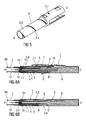
- Figure 5
- an isometric view of a needle shroud,
- Figures 6A and 6B
- two different sectional views of the auto-injector according to the first embodiment after an injection has been performed,
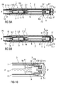
- Figures 7A and 7B
- two different sectional views of an auto-injector according to a second embodiment of the invention,
- Figure 8
- a sectional view of a distal end section of the auto-injector according to the second embodiment of the invention,
- Figure 9A and 9B
- two different sectional views of an auto-injector according to a third embodiment of the invention,
- Figure 10
- a sectional view of a distal end section of the auto-injector according to the third embodiment of the invention.
- Corresponding parts are marked with the same reference symbols in all figures.
-
Figures 1A and 1B show two sectional views of an essentially cylindrical auto-injector 1 according to a first embodiment of the invention, wherein the sectional plane shown infigure 1A is oriented perpendicularly to the one shown infigure 1B . The auto-injector 1 comprises ahousing 2, aproximal needle shroud 3, asyringe retainer 4 adapted to mount and move translatably with apre-filled syringe 5 within thehousing 2, acoupling shroud 6 slidably arranged within thehousing 2 and arelease element 7 hinged to a lateral side of the substantiallycylindrical housing 2 of the auto-injector 1. - A single drive means 8 is arranged between the distal end of the
housing 2 and thecoupling shroud 6 to bias thecoupling shroud 6 in a proximal direction P towards the skin of a patient receiving an injection. - According to one possible embodiment of the invention, the drive means 8 is arranged as a single, conventional compression spring.
- The
coupling shroud 6 is releasably coupled to aplunger 9 that is connected to astopper 10 fluid-tightly sealing a distal end of asyringe barrel 11 containing a dose of a medicament M. An inner cavity of thesyringe barrel 11 is in fluid communication with aninjection needle 12, so that the dose of the medicament M may be expelled through theinjection needle 12 by displacing thestopper 10 in the proximal direction P. - Before the injection, the
coupling shroud 6 abuts against a distal end of therelease element 7 to releasably retain thecoupling shroud 6 in a first position I, wherein thecoupling shroud 7 is located at a distal end of thehousing 2. The drive means 8 is compressed, so that thecoupling shroud 6 is strongly biased in the proximal direction P. - The
plunger 9 extends from thesyringe barrel 11 in a distal direction D and comprises a shoulder 9.1 of increased diameter. Thecoupling shroud 6 comprises an inwardly protruding coupling catch 6.1 that bears against the shoulder 9.1 so that theplunger 9 and thecoupling shroud 6 may be jointly moved in the proximal direction P by the action of the relaxing drive means 8. - The proximal end of the
needle shroud 3 is designed to be pushed against the skin surface of the patient during the injection. Edges of theneedle shroud 3 may thus be smoothed to avoid injuries. Theneedle shroud 3 is slidably arranged within thehousing 2 of the auto-injector 1, so that theneedle shroud 3 may be pushed from an advanced position PA shown infigures 1A and 1B in the distal direction D. A biasing means 13 bears against theneedle shroud 3 and thehousing 2 to bias theneedle shroud 3 towards the advanced position PA. - An annular
rotating collar 14 engages an outer surface of theneedle shroud 3. The rotatingcollar 14 rotates around an axis of the substantially cylindrical auto-injector 1 when theneedle shroud 3 is longitudinally displaced in the proximal and/or the distal direction P, D. The rotatingcollar 14 acts as a damping means that creates friction to slow down the movement of theneedle shroud 3 and to reduce the pressure exerted onto the skin of the patient receiving the injection. - The
release element 7 hinged to thehousing 2 works like a see-saw: a proximal section may be pushed radially inwards, whereby therelease element 7 pivots about ahinge 15, so that the distal section of therelease element 7 moves radially outwards and thecoupling shroud 6 is disengaged to release the drive means 8. - The auto-
injector 1 comprises safety means S that prevent an early release of the drive means 8. The safety means S ensure that theneedle shroud 3 is pushed against the skin of the person receiving the injection before the drive means 8 may be released. - According to the first embodiment of the invention, the safety means S comprise a blocking
element 16 slidably arranged with thehousing 2. When theneedle shroud 3 is positioned in the advanced position PA, the blockingelement 16 is positioned to prevent a pivoting movement of therelease element 7 and thus a release of thecoupling shroud 6. A radially outwards protruding blocking projection 16.1 of the blockingelement 16 is located opposite to an inward protrusion 7.1 formed to therelease element 7. If the proximal section of therelease element 7 is pushed inwards, the inward protrusion 7.1 abuts against the blocking projection 16.1 to limit the pivoting movement of therelease element 7, so that a release of thecoupling shroud 6 and the drive means 8 is prevented. -
Figure 2 shows a proximal section of the auto-injector 1 in a sectional view with the blockingelement 16 positioned to prevent an inadvertent actuation of the hingedrelease element 7 to release the drive means 8. - A distal end of the
needle shroud 3 is clipped to thehousing 2 and retained between two inwardly protruding retaining protrusions 2.1 formed into an inner surface of thehousing 2. The two retaining protrusions 2.1 are longitudinally displaced from each other to limit the range of axial displacement of theneedle shroud 3 with respect to thehousing 2. A boss 3.1 formed into an outer surface of theneedle shroud 3 bears against an inner surface of the blockingelement 16, so that the blockingelement 16 may move with theneedle shroud 3 in the proximal direction P to deblock therelease element 7. - The blocking projection 16.1 comprises a central indention that forces a user of the auto-
injector 1 to perform a sequence of actions necessary to inject the dose of the medicament M in the proper order. If therelease element 7 is pushed inwards before theneedle shroud 3 is moved proximally from the advanced position PA towards a retracted position PR (seeFigure 3 ) by pushing theneedle shroud 3 towards the skin of the patient, the inward projection 7.1 is retained in the central indentation of the blocking projection 16.1, so that both the longitudinal displacement of theneedle shroud 3 and the pivoting movement of therelease element 7 is blocked. - A proper sequence of actions for injecting the dose of the medicament M is described in the following. First, the user pushes the
needle shroud 3 against the skin to move theneedle shroud 3 distally to the retracted position PR illustrated infigure 3 . The blockingelement 16 jointly moves with theneedle shroud 3 in the distal direction D, so that therelease element 7 may be manually actuated to pivot about thehinge 15, whereby the drive means 8 are released. - Upon release of the drive means 8, the
coupling shroud 6 is urged in the proximal direction P. The single and fully compressed drive means 8 drives thecoupling shroud 6 and theplunger 9 coupled thereto in the proximal direction P. Thecoupling shroud 6 first pushes thesyringe retainer 4 by means ofplunger 9,stopper 10 and the friction betweenstopper 10 andsyringe 11 proximally to insert theinjection needle 12 into the skin of the patient and a first clip connection 2.2 formed into a lateral side of thehousing 2 latches to an outward protrusion 4.1 of thesyringe retainer 4, as illustrated in more detail infigure 4B . - The
syringe retainer 4 and thepre-filled syringe 5 mounted thereto is now locked to thehousing 2. Thecoupling shroud 6 is moved further in the proximal direction P by the action of the relaxing drive means 8, whereby theplunger 9 is depressed into thesyringe barrel 11 to expel the dose of the medicament M contained therein through theinjection needle 12. -
Figure 4A and 4B show two sectional views of the auto-injector 1 according to the first embodiment of the invention with theplunger 9 fully depressed within thesyringe barrel 11. The dose of the medicament M has been delivered beneath the skin of the patient. Thecoupling shroud 6 is located in an intermediate second position II. The drive means 8 is not yet completely discharged and biases thecoupling shroud 6 in the proximal direction P. The shoulder 9.1 engages a ramp of the coupling catch 6.1 to deflect the coupling catch 6.1 in a radial outward direction. An aperture 2.3 is formed into thehousing 2 to allow for a radial outward deflection of the coupling catch 6.1, so that the coupling catch 6.1 overcomes the shoulder 9.1 decoupling thecoupling shroud 6 from theplunger 9. - In a possible embodiment of the invention, the aperture 2.3 defining the second position II is located at a longitudinal position along the
housing 2 that allows for a full depression of theplunger 9 completely emptying thesyringe barrel 11 before theplunger 9 is decoupled from thecoupling shroud 6. - Alternatively, the aperture 2.3 defining the second position II may be located at a longitudinal position along the
housing 2 that allows for an adjustment space accounting for manufacturing tolerances. The adjustment space is dimensioned as to allow for a reliable decoupling of theplunger 9 from thecoupling shroud 6 even if the parts constituting the auto-injector 1 comprise mismatch in mould or are slightly misaligned. In this alternative embodiment, the dose of the medicament M may or may not be completely expelled before theplunger 9 is decoupled from thecoupling shroud 6. - The retaining protrusions 2.1 are elastically supported and may be deflected radially outwards to release the
needle shroud 3. Thecoupling shroud 6 engages a ramp of the retaining protrusions 2.1 and splays the retaining protrusions 2.1 outwards, whereby theneedle shroud 3 is released and allowed to move proximally from the retracted position PR towards an extended safe position PS. - The drive means 8 is still partially loaded when the
coupling shroud 6 is located in the second position II. In a possible embodiment of the invention the biasing force of the drive means 8 exerted on thecoupling shroud 6 in the second position II is about 10 N. - The
coupling shroud 6 bears against a distal end of theneedle shroud 3, so that theneedle shroud 3 may be moved to the safe position PS by the action of the further relaxing drive means 8. As the biasing force exerted onto theneedle shroud 3 by the drive means 8 may be relatively large and could even bruise the patient, the rotatingcollar 14 is arranged within thehousing 2 to partially absorb the excess energy of the drive means 8 and slow down the proximal movement of theneedle shroud 3 by generating friction. -
Figure 5 shows an isometric view of theneedle shroud 3. A helical recess 3.2 is formed into a tubular proximal section 3.3 of theneedle shroud 3. The proximal section 3.3 of theneedle shroud 3 is inserted into the annularrotating collar 14, wherein a pin 14.1 formed to an inner surface of therotating collar 14 protrudes into the helical recess 3.2 as shown infigure 6A . The linear translatory movement ofneedle shroud 3 towards the safe position PS thus causes therotating collar 14 to rotate within thehousing 2 around the axis of the auto-injector 1. -
Figures 6A and 6B show two different sectional views of the auto-injector 1 according to the first embodiment of the invention after the injection has been performed. Theneedle shroud 3 is permanently locked to the safe position PS by a second clip connection 2.4 formed into thehousing 2. Theneedle shroud 3 surrounds theinjection needle 12 and extends a suitable distance proximally beyond the needle tip to avoid accidental needle stick injuries after the auto-injector 1 has been used. -
Figures 7A and 7B show two different sectional views of an auto-injector 1 according to a second embodiment of the invention before the injection. The sectional plane shown infigure 7A is oriented perpendicularly to the sectional plane shown infigure 7B . - The
needle shroud 3 of the auto-injector 1 according to the second embodiment substantially extends over the axial length of thehousing 2. Before the injection, theneedle shroud 3 is mounted to thehousing 2 by the retaining protrusions 2.1 that protrude into orifices formed into a lateral side of theneedle shroud 3. The orifices comprise a longitudinal length that allows theneedle shroud 3 to be slid from the advanced position PA to the retracted position PR. - A retaining catch 2.5 is formed to an inner surface of the
housing 2 and protrudes through an opening formed into theneedle shroud 3 to releasably mount thesyringe retainer 4 retaining thepre-filled syringe 5. The retaining catch 2.5 comprises a bevelled ramp and is deflectable in a radial outward direction. The retaining catch 2.5 latches to the outward protrusion 4.1 formed to the outer surface of thesyringe retainer 4 when theneedle shroud 3 is in the advanced position PA - The
needle shroud 3 abuts against the bevelled ramp of the retaining catch 2.5 when theneedle shroud 3 is moved from the advanced position PA in the distal direction D, whereby the retaining catch 2.5 is deflected in a radial outward direction and disengages the outward protrusion 4.1, so that thesyringe retainer 4 may be moved in the proximal direction P. - The
release element 7, shown in more detail infigure 8 , is arranged as a push button and mounted to a distal end of thehousing 2. Therelease element 7 may be pushed in the proximal direction P to release the drive means 8 when theneedle shroud 3 is in the retracted position PR, whereas therelease element 7 and thus the release of the drive means 8 is blocked when theneedle shroud 7 is in the advanced position PA. - According to the second embodiment of the invention, the safety means S that prevent the early release of the drive means 8 comprises clips 2.6 that may deflect in a radial outward direction and a
bushing 17 locking theplunger 9 before use of the auto-injector 1. - Before the auto-
injector 1 is used, the clips 2.6 formed to thehousing 8 latch to therelease element 7. (SeeFigure 7B ) The clips 2.6 block the movement of therelease element 7 in the proximal direction P, so that a manual actuation of therelease element 7 is prevented as long as theneedle shroud 3 is in the advanced position PA. A distal movement of therelease element 7 is blocked by a first detent 2.7 engaging an inner surface of therelease element 7. - The clip 2.6 comprises a ramp that the
needle shroud 3 engages when pushed distally from the advanced position PA to the retracted position PR, whereby the clip 2.6 is deflected radially outwards to disengage theneedle shroud 3. Therelease element 7 may be pushed in the proximal direction P when theneedle shroud 3 is in the retracted position PR. - The
plunger 9 comprises a distal end 9.2 of increased diameter that is retained in thebushing 17 firmly attached to a distal end of thehousing 2. Thebushing 17 comprises an inner surface corresponding to the distal end 9.2 of theplunger 9 that engages the distal end 9.2 in a locked position L to lock theplunger 9 and thecoupling shroud 6 coupled thereto to thehousing 2 before use of the auto-injector 1. Thebushing 17 abuts radially against an annular inner collar 7.2 of therelease element 7 in the locked position L shown infigures 7A and 7B . A radial outward deflection of thebushing 17 releasing theplunger 9 is thus prevented. -
Figure 8 shows a sectional view of a distal end section of the auto-injector 1 according to the second embodiment of the invention. Theneedle shroud 3 is located in the retracted position PR and therelease element 7 is pushed in the proximal direction P, so that thebushing 17 disengages the annular inner collar 7.2 of therelease element 7. Thebushing 17 is positioned in an unlocked position U and may deflect outwardly to release theplunger 9. - Furthermore, the
bushing 17 acts as a counter bearing for the drive means 8 bearing against thebushing 17 in the distal direction D. -
Figure 9A and 9B show two different sectional views of an auto-injector 1 according to a third embodiment of the invention, wherein therelease element 7 is arranged as an outer sleeve extending over a substantial length of the auto-injector 1. - According to the third embodiment of the invention, the safety means S that prevent the early release of the drive means 8 comprise clips 2.6, second and third detents 2.8, 7.3, a locking catch 6.2 formed to the
coupling shroud 6 and thebushing 17 that comprises an inner sleeve 17.1 receiving a lug 7.4, wherein the locking catch 6.2 latches to a collar 17.2 of the inner sleeve 17.1. - The
release element 7 of the third embodiment is gripped by a user to perform the injection. When theneedle shroud 3 is in the advanced position PA, the proximal displacement of therelease element 7 is blocked by the clips 2.6 in a similar manner as in the second embodiment described herein above. - Additionally, the release element is releasably retained in position before the injection by the second and the third detents 2.8, 7.3 respectively formed to an outer surface of the
housing 2 and to an inner surface of therelease element 7, wherein the second and third detents 2.8, 7.3 comprise correspondingly shaped ramps facing each other. - The
bushing 17 of the third embodiment comprises the inner sleeve 17.1 that receives the lug 7.4 formed to an inner surface of therelease element 7. A proximal end of the lug 7.4 snugly fits in the central aperture of the inner sleeve 17.1, so that an inward deflection of the inner sleeve 17.1 is prevented. - The inner sleeve 17.1 comprises a collar 17.2. An inwardly protruding locking catch 6.2 of the
coupling shroud 6 latches to the collar 17.2 before use of the auto-injector 1 to releasably retain thecoupling shroud 6 in the first position I. -
Figure 10 shows a sectional view of a distal end section of the auto-injector 1 according to the third embodiment of the invention. Therelease element 7 is actuated and moved in the proximal direction P. The proximal end of the lug 7.4 disengages the inner sleeve 17.1 of thebushing 17, so that the inner sleeve 17.1 may bend radially inwards, whereby the locking catch 6.2 disengages the collar 17.2 and releases thecoupling shroud 8 and the drive means 8. -
- 1
- auto-injector
- 2
- housing
- 2.1
- retaining protrusion
- 2.2
- first clip connection
- 2.3
- aperture
- 2.4
- second clip connection
- 2.5
- retaining catch
- 2.6
- clip
- 2.7
- first detent
- 2.8
- second detent
- 3
- needle shroud
- 3.1
- boss
- 3.2
- helical recess
- 3.3
- proximal section
- 4
- syringe retainer
- 4.1
- outward protrusion
- 5
- pre-filled syringe
- 6
- coupling shroud
- 6.1
- coupling catch
- 6.2
- locking catch
- 7
- release element
- 7.1
- inward protrusion
- 7.2
- inner collar
- 7.3
- second detent
- 7.4
- lug
- 8
- drive means
- 9
- plunger
- 9.1
- shoulder
- 9.2
- distal end
- 10
- stopper
- 11
- syringe barrel
- 12
- injection needle
- 13
- biasing means
- 14
- rotating collar
- 14.1
- pin
- 15
- hinge
- 16
- blocking element
- 16.1
- blocking projection
- 17
- bushing
- 17.1
- inner sleeve
- 17.2
- collar
- M
- medicament
- S
- safety means
- I
- first position
- II
- second position
- PA
- advanced position
- PR
- retracted Position
- PS
- safe position
- L
- locked position
- U
- unlocked position
- P
- proximal direction
- D
- distal direction
Claims (13)
- Auto-injector (1) for administering a dose of a liquid medicament (M), comprising- a substantially cylindrical housing (2) arranged to contain a pre-filled syringe (5) filled with the medicament (M),- a needle shroud (3) slibably arranged with respect to the housing (2) and adapted to rest on the skin of a patient receiving an injection,- a releasable drive means (8) arranged within the housing (2) that is capable of, upon release, translating the needle shroud (3) in a proximal direction (P) towards a safe position (PS),- a rotating collar (14) rotatably arranged within the housing (2),
wherein the needle shroud (3) in the safe position (PS) surrounds the injection needle (12) and wherein the rotating collar (14) engages the needle shroud (3) in a manner that forces the rotating collar (14) to rotate within the housing (2) when the needle shroud (3) is translated in the proximal direction (P) towards the safe position (PS). - Auto-injector (1) according to claim 1,
characterized in that the rotating collar (14) comprises a pin (14.1) that engages a helical recess (3.2) formed into the needle shroud (3). - Auto-injector (1) according to claim 1 or 2,
characterized in that the needle shroud (3) is slidable from an advanced position (PA) in a distal direction (D) to a retracted position (PR) and from the retracted position (PR) in the proximal direction (P) to the safe position (PS). - Auto-injector (1) according to one of the previous claims,
characterized in that the drive means (8) arranged to be released by manual actuation of a release element (7) that is hinged to the housing (2) or slidably arranged with respect to the housing (2). - Auto-injector (1) according to claim 3 or 4,
characterized in that safety means (S) are arranged to cooperate with the needle shroud (3) to prevent a release of the drive means (8) when the needle shroud (3) is in the advanced position (PA). - Auto-injector (1) according to claim 5,
characterized in that the safety means (S) comprise a blocking element (16) that is slidably arranged relative to the housing (2), wherein the blocking element (16) is arranged to limit a pivoting movement of the release element (7) hinged to a lateral side of the housing (2) when the needle shroud (3) is in the advanced position (PA) and wherein the blocking element (16) is arranged to allow the release element (7) to pivot about a hinge (15) when the needle shroud (3) is in the retracted position (PR). - Auto-injector (1) according to claim 5,
characterized in that the safety means (S) comprise a bushing (17) that engages a plunger (9) of the pre-filled syringe (5) and/or a coupling shroud (6) slidably arranged within the housing (2) to prevent the release of the drive means (8). - Auto-injector (1) according to claim 7,
characterized in that the drive means (8) is capable of, upon release, driving the coupling shroud (6) releasably coupled to the plunger (9) from a first position (I) in the proximal direction (P), wherein the proximal translatory movement of the coupling shroud (6) with respect to the housing (2)- translates a syringe retainer (4) receiving the pre-filled syringe (5) in the proximal direction (P) to expose the injection needle (12) of the pre-filled syringe (5),- depresses the plunger (9) connected to a stopper (10) into the syringe barrel (11) to expel the dose of medicament (M) and- translates the needle shroud (3) in the proximal direction (P). - Auto-injector (1) according to claim 8,
characterized in that the syringe retainer (4) is releasably mounted to the housing (2), wherein the needle shroud (3) in the retracted position (PR) is arranged to release the syringe retainer (4) to allow for the proximal translation of the syringe retainer (4) with respect to the housing (2). - Auto-injector (1) according to one of the claims 7 to 9,
characterized in that the coupling shroud (6) is arranged to be decoupled from the plunger (9) at a pre-determined second position (II) defined by an aperture (2.3) formed into the housing (2). - Auto-injector (1) according to one of the claims 7 to 10,
characterized in that a coupling catch (6.1) is arranged to abut against a shoulder (9.1) formed to the plunger (9) to releasably couple the plunger (9) to the coupling shroud (6). - Auto-injector (1) according to claim 11,
characterized in that the aperture (2.3) allows the coupling catch (6.1) to deflect radially outwards to decouple the coupling shroud (6) from the plunger (9) at the second position (II). - Auto injector (1) according to one of the previous claims,
characterized in that the drive means (8) is arranged as a single compression spring.
Priority Applications (17)
| Application Number | Priority Date | Filing Date | Title |
|---|---|---|---|
| EP10196067A EP2468330A1 (en) | 2010-12-21 | 2010-12-21 | Auto-injector |
| PCT/EP2011/073502 WO2012085021A1 (en) | 2010-12-21 | 2011-12-21 | Auto-injector |
| DK11802930.5T DK2654840T3 (en) | 2010-12-21 | 2011-12-21 | AUTO INJECTOR |
| EP22174833.8A EP4070831A1 (en) | 2010-12-21 | 2011-12-21 | Auto-injector |
| JP2013545329A JP6080775B2 (en) | 2010-12-21 | 2011-12-21 | Automatic syringe |
| CA2821635A CA2821635A1 (en) | 2010-12-21 | 2011-12-21 | Auto-injector |
| US13/993,528 US9724472B2 (en) | 2010-12-21 | 2011-12-21 | Auto-injector |
| EP22156158.2A EP4015021A1 (en) | 2010-12-21 | 2011-12-21 | Auto-injector |
| EP11802930.5A EP2654840B1 (en) | 2010-12-21 | 2011-12-21 | Auto-injector |
| US15/669,571 US10729853B2 (en) | 2010-12-21 | 2017-08-04 | Auto-injector |
| US16/909,107 US11833331B2 (en) | 2010-12-21 | 2020-06-23 | Auto-injector |
| US17/706,444 US11458252B2 (en) | 2010-12-21 | 2022-03-28 | Auto-injector |
| US17/706,389 US11400217B2 (en) | 2010-12-21 | 2022-03-28 | Auto-injector |
| US17/845,521 US11471601B1 (en) | 2010-12-21 | 2022-06-21 | Auto-injector |
| US17/952,801 US11612691B2 (en) | 2010-12-21 | 2022-09-26 | Auto-injector |
| US17/994,961 US11607495B1 (en) | 2010-12-21 | 2022-11-28 | Auto-injector |
| US18/498,416 US20240058536A1 (en) | 2010-12-21 | 2023-10-31 | Auto-Injector |
Applications Claiming Priority (1)
| Application Number | Priority Date | Filing Date | Title |
|---|---|---|---|
| EP10196067A EP2468330A1 (en) | 2010-12-21 | 2010-12-21 | Auto-injector |
Publications (1)
| Publication Number | Publication Date |
|---|---|
| EP2468330A1 true EP2468330A1 (en) | 2012-06-27 |
Family
ID=43837882
Family Applications (4)
| Application Number | Title | Priority Date | Filing Date |
|---|---|---|---|
| EP10196067A Ceased EP2468330A1 (en) | 2010-12-21 | 2010-12-21 | Auto-injector |
| EP22156158.2A Pending EP4015021A1 (en) | 2010-12-21 | 2011-12-21 | Auto-injector |
| EP22174833.8A Pending EP4070831A1 (en) | 2010-12-21 | 2011-12-21 | Auto-injector |
| EP11802930.5A Active EP2654840B1 (en) | 2010-12-21 | 2011-12-21 | Auto-injector |
Family Applications After (3)
| Application Number | Title | Priority Date | Filing Date |
|---|---|---|---|
| EP22156158.2A Pending EP4015021A1 (en) | 2010-12-21 | 2011-12-21 | Auto-injector |
| EP22174833.8A Pending EP4070831A1 (en) | 2010-12-21 | 2011-12-21 | Auto-injector |
| EP11802930.5A Active EP2654840B1 (en) | 2010-12-21 | 2011-12-21 | Auto-injector |
Country Status (6)
| Country | Link |
|---|---|
| US (9) | US9724472B2 (en) |
| EP (4) | EP2468330A1 (en) |
| JP (1) | JP6080775B2 (en) |
| CA (1) | CA2821635A1 (en) |
| DK (1) | DK2654840T3 (en) |
| WO (1) | WO2012085021A1 (en) |
Cited By (21)
| Publication number | Priority date | Publication date | Assignee | Title |
|---|---|---|---|---|
| WO2014198793A1 (en) * | 2013-06-11 | 2014-12-18 | Cilag Gmbh International | Sliding sleeve attachment for an injection device |
| US8939958B2 (en) | 2008-06-19 | 2015-01-27 | Cilag Gmbh International | Fluid transfer assembly for a syringe |
| US8968236B2 (en) | 2005-04-06 | 2015-03-03 | Cilag Gmbh International | Injection device |
| CN104582765A (en) * | 2012-08-20 | 2015-04-29 | 赛诺菲-安万特德国有限公司 | Drug delivery device and method for detecting contact |
| US9028453B2 (en) | 2008-06-19 | 2015-05-12 | Cilag Gmbh International | Reusable auto-injector |
| US9028451B2 (en) | 2006-06-01 | 2015-05-12 | Cilag Gmbh International | Injection device |
| US9072833B2 (en) | 2006-06-01 | 2015-07-07 | Cilag Gmbh International | Injection device |
| US9358346B2 (en) | 2005-08-30 | 2016-06-07 | Cilag Gmbh International | Needle assembly for a prefilled syringe system |
| US9649441B2 (en) | 2005-04-06 | 2017-05-16 | Cilag Gmbh International | Injection device (bayonet cap removal) |
| US9675758B2 (en) | 2004-05-28 | 2017-06-13 | Cilag Gmbh International | Injection device |
| US9675757B2 (en) | 2004-05-28 | 2017-06-13 | Cilag Gmbh International | Injection device |
| US9682194B2 (en) | 2008-06-19 | 2017-06-20 | Cilag Gmbh International | Re-useable auto-injector with filling means |
| US9731080B2 (en) | 2005-04-06 | 2017-08-15 | Cilag Gmbh International | Injection device |
| US9757520B2 (en) | 2006-06-01 | 2017-09-12 | Cilag Gmbh International | Injection device |
| US9770558B2 (en) | 2005-09-27 | 2017-09-26 | Cilag Gmbh International | Auto-injection device with needle protecting cap having outer and inner sleeves |
| US9895493B2 (en) | 2004-05-28 | 2018-02-20 | Cilag Gmbh International | Injection device |
| US10709849B2 (en) | 2013-06-11 | 2020-07-14 | Cilag Gmbh International | Guide for an injection device |
| US10799646B2 (en) | 2013-06-11 | 2020-10-13 | Cilag Gmbh International | Injection device |
| US11123492B2 (en) | 2013-06-11 | 2021-09-21 | Cilag Gmbh International | Injection device |
| WO2021198483A1 (en) * | 2020-04-03 | 2021-10-07 | Sanofi | Injector device with distraction mechanism |
| US11173255B2 (en) | 2013-06-11 | 2021-11-16 | Cilag Gmbh International | Injection device |
Families Citing this family (25)
| Publication number | Priority date | Publication date | Assignee | Title |
|---|---|---|---|---|
| JP5807021B2 (en) | 2010-02-18 | 2015-11-10 | サノフィ−アベンティス・ドイチュラント・ゲゼルシャフト・ミット・ベシュレンクテル・ハフツング | Automatic syringe |
| EP2399635A1 (en) | 2010-06-28 | 2011-12-28 | Sanofi-Aventis Deutschland GmbH | Auto-injector |
| EP2438944A1 (en) * | 2010-10-08 | 2012-04-11 | Sanofi-Aventis Deutschland GmbH | Auto-injector |
| EP2468332A1 (en) * | 2010-12-21 | 2012-06-27 | Sanofi-Aventis Deutschland GmbH | Auto-injector |
| EP2468330A1 (en) | 2010-12-21 | 2012-06-27 | Sanofi-Aventis Deutschland GmbH | Auto-injector |
| EP2468333A1 (en) | 2010-12-21 | 2012-06-27 | Sanofi-Aventis Deutschland GmbH | Auto-injector |
| USRE48593E1 (en) | 2010-12-21 | 2021-06-15 | Sanofi-Aventis Deutschland Gmbh | Auto-injector |
| US9084849B2 (en) | 2011-01-26 | 2015-07-21 | Kaleo, Inc. | Medicament delivery devices for administration of a medicament within a prefilled syringe |
| ES2627823T3 (en) * | 2012-10-05 | 2017-07-31 | Carebay Europe Limited | DRUG ADMINISTRATION DEVICE |
| EP2823841A1 (en) | 2013-07-09 | 2015-01-14 | Sanofi-Aventis Deutschland GmbH | Autoinjector |
| CN105828851B (en) | 2013-11-28 | 2020-04-28 | 艾斯曲尔医疗公司 | Housing for a medicament delivery device |
| SG10201400686VA (en) * | 2014-03-14 | 2015-10-29 | Sg Meditech Pte Ltd | A cannulation assembly and method |
| EP2923714A1 (en) | 2014-03-28 | 2015-09-30 | Sanofi-Aventis Deutschland GmbH | Autoinjector triggered by skin contact |
| AU2015372441A1 (en) | 2014-12-23 | 2017-08-10 | Automed Pty Ltd | Delivery apparatus, system and associated methods |
| GB2537638A (en) * | 2015-04-21 | 2016-10-26 | Consort Medical Plc | Medicament delivery device |
| JP6830067B2 (en) | 2015-06-30 | 2021-02-17 | カレオ,インコーポレイテッド | Automatic syringe that administers medication in a prefilled syringe |
| US11033686B2 (en) * | 2016-05-18 | 2021-06-15 | Shl Medical Ag | Administration mechanism for a medicament delivery device |
| US10702652B2 (en) * | 2016-11-15 | 2020-07-07 | Adam Teach | Injection device |
| CA3043593C (en) | 2016-11-15 | 2021-04-20 | Eli Lilly And Company | Medication delivery device with mechanical locking system |
| AU2017379094B2 (en) | 2016-12-23 | 2023-08-24 | Kaleo, Inc. | Medicament delivery device and methods for delivering drugs to infants and children |
| US10357619B1 (en) | 2018-02-08 | 2019-07-23 | Chalbourne Brasington | Auto-injection device |
| WO2019175665A2 (en) | 2018-03-13 | 2019-09-19 | Mylan Uk Healthcare Ltd. | Devices for injecting medicaments and methods of use |
| EP3801694A4 (en) | 2018-06-08 | 2022-03-16 | Antares Pharma, Inc. | Auto-insert injector |
| CA3145580A1 (en) | 2019-08-09 | 2021-02-18 | Kaleo, Inc. | Devices and methods for delivery of substances within a prefilled syringe |
| US11957542B2 (en) | 2020-04-30 | 2024-04-16 | Automed Patent Holdco, Llc | Sensing complete injection for animal injection device |
Citations (4)
| Publication number | Priority date | Publication date | Assignee | Title |
|---|---|---|---|---|
| US20020095120A1 (en) | 2000-08-29 | 2002-07-18 | Andre Larsen | Automatic injection device |
| GB2438592A (en) * | 2006-06-01 | 2007-12-05 | Cilag Gmbh Int | Injection device with a damper |
| WO2009040602A1 (en) * | 2007-09-25 | 2009-04-02 | Becton Dickinson France | Autoinject0r with deactivating means moveable by a safety shield |
| WO2009062508A1 (en) * | 2007-11-12 | 2009-05-22 | Bang & Olufsen Medicom A/S | Auto injector with a rotatable release shaft |
Family Cites Families (145)
| Publication number | Priority date | Publication date | Assignee | Title |
|---|---|---|---|---|
| US4964866A (en) | 1989-11-22 | 1990-10-23 | Becton, Dickinson And Company | Needle sheath assembly |
| ES2074771T3 (en) | 1991-07-24 | 1995-09-16 | Medico Dev Investment Co | INJECTOR. |
| DE4229068C2 (en) | 1992-09-01 | 1994-06-16 | Bosch Gmbh Robert | Accelerator switch and manufacturing method |
| DE69427226T2 (en) * | 1993-03-24 | 2001-08-30 | Owen Mumford Ltd | DEVICE FOR INJECTION |
| US5478316A (en) | 1994-02-02 | 1995-12-26 | Becton, Dickinson And Company | Automatic self-injection device |
| US5843036A (en) | 1996-08-23 | 1998-12-01 | Becton Dickinson And Company | Non-dosing cartridge for an injection device |
| IE970782A1 (en) | 1997-10-22 | 1999-05-05 | Elan Corp | An improved automatic syringe |
| WO1999022792A1 (en) | 1997-11-03 | 1999-05-14 | Ermanno Greco | Self-injection device |
| EP1003581B1 (en) | 1998-01-30 | 2000-11-08 | Novo Nordisk A/S | An injection syringe |
| GB9808408D0 (en) | 1998-04-18 | 1998-06-17 | Owen Mumford Ltd | Improvements relating to injection devices |
| DE19819409A1 (en) | 1998-04-30 | 1999-11-11 | Schering Ag | Injection device |
| DE19822031C2 (en) | 1998-05-15 | 2000-03-23 | Disetronic Licensing Ag | Auto injection device |
| SE9803662D0 (en) | 1998-10-26 | 1998-10-26 | Pharmacia & Upjohn Ab | autoinjector |
| EP1200144A1 (en) | 1999-07-30 | 2002-05-02 | Medrad, Inc. | Injector systems and syringe adapters for use therewith |
| US6277099B1 (en) | 1999-08-06 | 2001-08-21 | Becton, Dickinson And Company | Medication delivery pen |
| US6673035B1 (en) | 1999-10-22 | 2004-01-06 | Antares Pharma, Inc. | Medical injector and medicament loading system for use therewith |
| US6692472B2 (en) | 2000-05-04 | 2004-02-17 | Novo Nordisk A/S | Injection device, a preassembled dose setting and injection mechanism for an injection device, and a method of assembling an injection device |
| US6663602B2 (en) | 2000-06-16 | 2003-12-16 | Novo Nordisk A/S | Injection device |
| SE518981C2 (en) * | 2000-12-14 | 2002-12-17 | Shl Medical Ab | autoinjector |
| EP2258425B1 (en) | 2001-05-16 | 2013-01-30 | Eli Lilly and Company | Medication injector apparatus |
| US20030105430A1 (en) * | 2001-11-30 | 2003-06-05 | Elan Pharma International Limited Wil House | Automatic injector |
| JP2005515383A (en) | 2002-01-25 | 2005-05-26 | ノボ・ノルデイスク・エー/エス | Linear actuator and medical dosing device incorporating such a linear actuator |
| DE10237258B4 (en) | 2002-08-14 | 2006-09-21 | Tecpharma Licensing Ag | injection device |
| GB0229345D0 (en) | 2002-12-17 | 2003-01-22 | Safe T Ltd | Hollow needle applicators |
| GB0304822D0 (en) | 2003-03-03 | 2003-04-09 | Dca Internat Ltd | Improvements in and relating to a pen-type injector |
| US20050027255A1 (en) | 2003-07-31 | 2005-02-03 | Sid Technologies, Llc | Automatic injector |
| DE20311996U1 (en) * | 2003-08-01 | 2003-10-16 | Hoelzle Dieter Tech Projekte | injection device |
| WO2005018721A1 (en) | 2003-08-12 | 2005-03-03 | Eli Lilly And Company | Medication dispensing apparatus with triple screw threads for mechanical advantage |
| DE10342058B4 (en) * | 2003-09-11 | 2007-10-25 | Tecpharma Licensing Ag | Administration device for an injectable product with a trigger safety device |
| IL157981A (en) * | 2003-09-17 | 2014-01-30 | Elcam Medical Agricultural Cooperative Ass Ltd | Auto-injector |
| DE10351596B4 (en) * | 2003-11-05 | 2007-10-11 | Tecpharma Licensing Ag | Autoinjector with variable dose |
| US20050101919A1 (en) | 2003-11-07 | 2005-05-12 | Lennart Brunnberg | Device for an injector |
| EP1541185A1 (en) | 2003-12-08 | 2005-06-15 | Novo Nordisk A/S | Automatic syringe with priming mechanism |
| EP1703929B1 (en) | 2003-12-18 | 2009-10-21 | Tecpharma Licensing AG | Releasable injection device |
| US20050222539A1 (en) | 2004-03-30 | 2005-10-06 | Pediamed Pharmaceuticals, Inc. | Automatic injection device |
| GB2414401B (en) | 2004-05-28 | 2009-06-17 | Cilag Ag Int | Injection device |
| GB2414775B (en) | 2004-05-28 | 2008-05-21 | Cilag Ag Int | Releasable coupling and injection device |
| CN101084028B (en) | 2004-10-21 | 2010-06-09 | 诺和诺德公司 | Injection device with torsion spring and rotatable display |
| ATE445429T1 (en) | 2004-10-21 | 2009-10-15 | Novo Nordisk As | INJECTION DEVICE WITH INTERNAL DOSE INDICATOR |
| JP4934051B2 (en) | 2004-11-24 | 2012-05-16 | エスホーエル メディカル アクチボラゲット | Injection device |
| CN101119761B (en) | 2004-11-24 | 2010-08-18 | Shl医药公司 | Injection device |
| DE102004063644A1 (en) | 2004-12-31 | 2006-07-20 | Tecpharma Licensing Ag | Device for the dosed administration of a fluid product with torsion spring drive |
| CA2595069C (en) | 2005-01-18 | 2011-05-03 | Wockhardt Americas Inc | Pen shaped medication injection devices |
| ES2633917T3 (en) | 2005-01-21 | 2017-09-26 | Novo Nordisk A/S | Automatic injection device with a superior release mechanism |
| GB2424838B (en) | 2005-04-06 | 2011-02-23 | Cilag Ag Int | Injection device (adaptable drive) |
| US20060276753A1 (en) | 2005-06-01 | 2006-12-07 | Victor Kronestedt | Device for delivering medicament |
| US9011386B2 (en) | 2005-06-01 | 2015-04-21 | Shl Group Ab | Device for delivering medicament |
| DE102005025424A1 (en) | 2005-06-02 | 2006-12-07 | Tecpharma Licensing Ag | Injection device, especially automatic injector or injection pen, has drive-off member propelled by surrounding torsional spring, for efficient delivery of product to patient |
| US20080234633A1 (en) | 2005-07-08 | 2008-09-25 | Novo Nordisk A/S | Injection Device |
| DE102005052502A1 (en) | 2005-11-03 | 2007-05-16 | Tecpharma Licensing Ag | Auto-injector activation trigger element |
| GB2433032A (en) | 2005-12-08 | 2007-06-13 | Owen Mumford Ltd | Syringe with dose adjustment means |
| GB0601309D0 (en) | 2006-01-23 | 2006-03-01 | Medical House The Plc | Injection device |
| US20090005735A1 (en) | 2006-03-03 | 2009-01-01 | Shl Group Ab | Medical Device with Orientation Sensitive Priming Mechanism |
| FR2899482A1 (en) | 2006-04-11 | 2007-10-12 | Becton Dickinson France Soc Pa | Automatic medicament/product injection device for patient, has safety shield coupled to housing, and provided in active state at end of needle insertion step before which product/medicament injection step is not started |
| WO2007129324A2 (en) | 2006-05-09 | 2007-11-15 | Gil Yigal | A disposable injecting device with auto-retraction mechanism |
| GB2438629B (en) * | 2006-06-01 | 2011-02-23 | Cilag Gmbh Int | Injection device |
| DE102006038103B4 (en) | 2006-08-14 | 2017-02-23 | Tecpharma Licensing Ag | Injection device with variable thread guide |
| EP2076302A1 (en) | 2006-09-15 | 2009-07-08 | TecPharma Licensing AG | Injection device with an automatically resettable dose limitation unit |
| FR2908753B1 (en) | 2006-11-16 | 2011-11-11 | Becton Dickinson France | DEVICE FOR AUTOMATICALLY DELIVERING SUCCESSIVE PRODUCT DOSES |
| DK1932558T3 (en) | 2006-12-13 | 2011-09-05 | Shl Group Ab | autoinjector |
| DE202007000578U1 (en) | 2007-01-15 | 2007-03-08 | Cilag Gmbh International | Injection device for operating with a nozzle has a cap with corresponding threads, a casing, an outlet opening, a sleeve and a central hub |
| JP5362591B2 (en) * | 2007-03-09 | 2013-12-11 | イーライ リリー アンド カンパニー | Delay mechanism for automatic injection equipment |
| JP5307038B2 (en) | 2007-03-23 | 2013-10-02 | エス・ホー・エル・グループ・アクチボラゲット | Automatic syringe |
| DE102007016811A1 (en) | 2007-04-05 | 2008-10-09 | Tecpharma Licensing Ag | Device for administering a fluid substance from a multi-chamber ampoule |
| JP5128658B2 (en) | 2007-04-05 | 2013-01-23 | テクファーマ・ライセンシング・アクチェンゲゼルシャフト | Administration device with functional drive element |
| RU2434651C1 (en) | 2007-06-19 | 2011-11-27 | Схл Груп Аб | Device for medication supply |
| US9242044B2 (en) | 2007-07-06 | 2016-01-26 | Novo Nordisk A/S | Automatic injection device |
| EP2192938B1 (en) | 2007-09-18 | 2017-10-25 | SHL Group AB | Automatic injection device with needle insertion |
| JP5432151B2 (en) | 2007-09-25 | 2014-03-05 | ベクトン・ディキンソン・フランス・エス.エー.エス. | Automatic syringe housed in external socket |
| WO2009040607A1 (en) | 2007-09-25 | 2009-04-02 | Becton Dickinson France | Autoinjector with deactivating means moveable by a safety shield |
| US8992484B2 (en) | 2008-01-23 | 2015-03-31 | Novo Nordisk A/S | Device for injecting apportioned doses of liquid drug |
| JP4977252B2 (en) | 2008-02-12 | 2012-07-18 | エス・ホー・エル・グループ・アクチボラゲット | Automatic syringe |
| DE102008011885A1 (en) | 2008-02-29 | 2009-09-10 | Tecpharma Licensing Ag | Dual function spring |
| EP2123317A1 (en) | 2008-05-20 | 2009-11-25 | Sanofi-Aventis Deutschland GmbH | Drive assembly suitable for use in drug delivery device and drug delivery device |
| US8177749B2 (en) | 2008-05-20 | 2012-05-15 | Avant Medical Corp. | Cassette for a hidden injection needle |
| EP2318075B1 (en) | 2008-08-05 | 2019-05-22 | Antares Pharma, Inc. | Multiple dosage injector |
| CN102202710B (en) | 2008-09-18 | 2013-08-21 | 贝克顿·迪金森公司 | Medical injector with rotatable body portions |
| WO2010033778A2 (en) | 2008-09-18 | 2010-03-25 | Becton, Dickinson And Company | Medical injector with dose knob activation for automated reconstitution |
| EP2362795B1 (en) * | 2008-09-29 | 2018-04-25 | Becton Dickinson France | Automatic injection device |
| JP5324656B2 (en) | 2008-10-01 | 2013-10-23 | エス・ホー・エル・グループ・アクチボラゲット | Drug delivery device driven by spiral spring |
| TWI555546B (en) | 2008-12-02 | 2016-11-01 | 賽諾菲阿凡提斯德意志有限公司 | Medication delivery device and method for operating a medication delivery device |
| US8840591B2 (en) | 2008-12-12 | 2014-09-23 | Sanofi-Aventis Deutschland Gmbh | Drive mechanism for a medication delivery device and medication delivery device |
| US8366680B2 (en) | 2008-12-12 | 2013-02-05 | Sanofi-Aventis Deutschland Gmbh | Resettable drive mechanism for a medication delivery device and medication delivery device |
| MY159791A (en) | 2008-12-12 | 2017-01-31 | Sanofi Aventis Deutschland | Resettable drive mechanism for a medication delivery device and medication delivery device |
| US9089652B2 (en) | 2008-12-12 | 2015-07-28 | Sanofi-Aventis Deutschland Gmbh | Drive mechanism for a medication delivery device and medication delivery device |
| US8968258B2 (en) | 2008-12-12 | 2015-03-03 | Sanofi-Aventis Deutschland Gmbh | Resettable drive mechanism for a medication delivery device and medication delivery device |
| GB0900930D0 (en) | 2009-01-20 | 2009-03-04 | Future Injection Technologies Ltd | Injection device |
| EP2208503A1 (en) | 2009-01-20 | 2010-07-21 | Sanofi-Aventis Deutschland GmbH | Drive assembly and medication delivery device |
| BRPI1008514A2 (en) | 2009-02-05 | 2016-03-08 | Sanofi Aventis Deutschland | "drug shipping device" |
| AU2010210158B2 (en) | 2009-02-05 | 2014-09-25 | Sanofi-Aventis Deutschland Gmbh | Medicament delivery devices |
| EP2401009B1 (en) | 2009-02-26 | 2012-11-28 | Tecpharma Licensing AG | Product container holder for an injection device and for receiving a product container |
| UA103228C2 (en) | 2009-03-13 | 2013-09-25 | Елі Ліллі Енд Компані | Apparatus for injecting a pharmaceutical with automatic syringe retraction following injection |
| EP2408493A1 (en) | 2009-03-20 | 2012-01-25 | Antares Pharma, Inc. | Hazardous agent injection system |
| DK2414004T3 (en) | 2009-03-31 | 2015-07-27 | Sanofi Aventis Deutschland | Improvements in and relating to devices for drug feed |
| US8617124B2 (en) | 2009-06-05 | 2013-12-31 | Shl Group Ab | Medicament delivery device |
| GB0913385D0 (en) | 2009-07-31 | 2009-09-16 | Medical House The Plc | Improved autoinjector |
| TW201127435A (en) | 2009-09-30 | 2011-08-16 | Sanofi Aventis Deutschland | Drive mechanism for a drug delivery device |
| GB0918145D0 (en) | 2009-10-16 | 2009-12-02 | Owen Mumford Ltd | Injector apparatus |
| DK2493529T3 (en) | 2009-10-26 | 2016-05-17 | Shl Group Ab | Drug delivery device |
| DK2536455T3 (en) | 2010-02-18 | 2014-06-23 | Sanofi Aventis Deutschland | FINGER PROTECTION FOR AN INJECTION DEVICE |
| EP2536453B1 (en) | 2010-02-18 | 2014-08-20 | Sanofi-Aventis Deutschland GmbH | Auto-injector |
| DK2536451T3 (en) | 2010-02-18 | 2018-07-16 | Sanofi Aventis Deutschland | Auto injector with a torsion spring |
| CA2790280A1 (en) | 2010-02-22 | 2011-08-25 | Sanofi-Aventis Deutschland Gmbh | Auto - injector with needle shroud and needle protection cap |
| WO2011101383A1 (en) | 2010-02-22 | 2011-08-25 | Sanofi-Aventis Deutschland Gmbh | Force transmission arrangement for auto-injector |
| DK2538993T3 (en) | 2010-02-22 | 2017-02-06 | Sanofi Aventis Deutschland | Auto injector with gearbox |
| UA117742C2 (en) | 2010-03-01 | 2018-09-25 | Елі Ліллі Енд Компані | DEVICE FOR AUTOMATIC IMMEDIATE INJECTION WITH DELAY MECHANISM, INCLUDING DUAL DESTINATION |
| EP2364740A1 (en) | 2010-03-09 | 2011-09-14 | Sanofi-Aventis Deutschland GmbH | Arrangement for transferring a translation of a drive means to a plunger |
| DK2544741T3 (en) | 2010-03-09 | 2016-08-29 | Shl Group Ab | DRUG ADMINISTRATIVE DEVICE |
| IT1398501B1 (en) | 2010-03-10 | 2013-03-01 | Menarini Int Operations Lu Sa | AUTOINECTOR DEVICE FOR TWO DRUG DOSES |
| RU2012138044A (en) | 2010-03-25 | 2014-04-27 | Нью Инджекшн Системз Лтд | SPRAYER |
| EP2583710B1 (en) | 2010-03-31 | 2021-11-10 | SHL Medical AG | Medicament delivery device comprising feedback signalling means |
| JP5722992B2 (en) | 2010-04-07 | 2015-05-27 | エス・ホー・エル・グループ・アクチボラゲットShl Group Ab | Drug delivery device |
| CN102946931B (en) | 2010-04-26 | 2015-09-16 | Shl集团有限责任公司 | Medicament delivery device |
| CN102946926B (en) | 2010-05-07 | 2014-12-10 | Shl集团有限责任公司 | Medicament delivery device |
| DK2579927T3 (en) | 2010-06-11 | 2018-06-06 | Sanofi Aventis Deutschland | DRIVE MECHANISM FOR A PHARMACEUTICAL DISPENSER AND MEDICINE DISPENSER |
| WO2011154486A1 (en) | 2010-06-11 | 2011-12-15 | Sanofi-Aventis Deutschland Gmbh | Drive mechanism for a drug delivery device and drug delivery device |
| US8961473B2 (en) | 2010-06-11 | 2015-02-24 | Sanofi-Aventis Deutschland Gmbh | Drive mechanism for a drug delivery device and drug delivery device |
| EP2399631A1 (en) | 2010-06-28 | 2011-12-28 | Sanofi-Aventis Deutschland GmbH | Auto-injector with injection damper |
| EP2399633A1 (en) | 2010-06-28 | 2011-12-28 | Sanofi-Aventis Deutschland GmbH | Needle safety arrangement and method for operating it |
| EP2399635A1 (en) | 2010-06-28 | 2011-12-28 | Sanofi-Aventis Deutschland GmbH | Auto-injector |
| WO2012000875A1 (en) | 2010-06-28 | 2012-01-05 | Sanofi-Aventis Deutschland Gmbh | Auto-injector |
| EP2399634A1 (en) | 2010-06-28 | 2011-12-28 | Sanofi-Aventis Deutschland GmbH | Needle safety arrangement and method for operating it |
| PL2555820T3 (en) | 2010-07-02 | 2015-08-31 | Carebay Holding Ltd Company No 681498 | Preservative-free follicle stimulating hormone solution delivery device |
| US9067024B2 (en) | 2010-07-02 | 2015-06-30 | Sanofi-Aventis Deutschland Gmbh | Safety device for a pre-filled syringe and injection device |
| WO2012045350A1 (en) | 2010-10-06 | 2012-04-12 | Tecpharma Licensing Ag | Locking and retaining mechanism for the needle guard sleeve of an injection device |
| EP2438942A1 (en) | 2010-10-08 | 2012-04-11 | Sanofi-Aventis Deutschland GmbH | Auto-injector |
| EP2438944A1 (en) | 2010-10-08 | 2012-04-11 | Sanofi-Aventis Deutschland GmbH | Auto-injector |
| EP2452711A1 (en) | 2010-11-12 | 2012-05-16 | Sanofi-Aventis Deutschland GmbH | Drive mechanism for a drug delivery device and drug delivery device |
| TWI476024B (en) | 2010-11-18 | 2015-03-11 | Shl Group Ab | Medicament delivery device |
| EP2646079A1 (en) | 2010-11-29 | 2013-10-09 | Sanofi-Aventis Deutschland GmbH | Drug delivery device having a collar and a linkage component |
| EP2468337A1 (en) | 2010-12-21 | 2012-06-27 | Sanofi-Aventis Deutschland GmbH | Back-end device for an auto-injector and auto-injector |
| EP2468333A1 (en) | 2010-12-21 | 2012-06-27 | Sanofi-Aventis Deutschland GmbH | Auto-injector |
| EP2468335A1 (en) | 2010-12-21 | 2012-06-27 | Sanofi-Aventis Deutschland GmbH | Auto-injector |
| EP2468336A1 (en) | 2010-12-21 | 2012-06-27 | Sanofi-Aventis Deutschland GmbH | Auto-injector |
| EP2468342A1 (en) | 2010-12-21 | 2012-06-27 | Sanofi-Aventis Deutschland GmbH | Front end for an auto-injector |
| EP2468332A1 (en) | 2010-12-21 | 2012-06-27 | Sanofi-Aventis Deutschland GmbH | Auto-injector |
| EP2468331A1 (en) | 2010-12-21 | 2012-06-27 | Sanofi-Aventis Deutschland GmbH | Auto-injector |
| EP2468329A1 (en) | 2010-12-21 | 2012-06-27 | Sanofi-Aventis Deutschland GmbH | Auto injector with a torsion spring |
| USRE48593E1 (en) | 2010-12-21 | 2021-06-15 | Sanofi-Aventis Deutschland Gmbh | Auto-injector |
| EP2468330A1 (en) | 2010-12-21 | 2012-06-27 | Sanofi-Aventis Deutschland GmbH | Auto-injector |
| EP2468334A1 (en) | 2010-12-21 | 2012-06-27 | Sanofi-Aventis Deutschland GmbH | Auto-injector |
| EP2489382A1 (en) * | 2011-02-18 | 2012-08-22 | Sanofi-Aventis Deutschland GmbH | Auto-injector |
| EP2540329A1 (en) | 2011-06-28 | 2013-01-02 | Sanofi-Aventis Deutschland GmbH | Needle assembly attachment and removal device |
| KR20140105557A (en) | 2011-12-15 | 2014-09-01 | 에스에이치엘 그룹 에이비 | Auto-injection device |
| WO2021008839A1 (en) | 2019-07-18 | 2021-01-21 | Shl Medical Ag | Support structure, medicament delivery device and method of assemblying |
-
2010
- 2010-12-21 EP EP10196067A patent/EP2468330A1/en not_active Ceased
-
2011
- 2011-12-21 EP EP22156158.2A patent/EP4015021A1/en active Pending
- 2011-12-21 WO PCT/EP2011/073502 patent/WO2012085021A1/en active Application Filing
- 2011-12-21 EP EP22174833.8A patent/EP4070831A1/en active Pending
- 2011-12-21 JP JP2013545329A patent/JP6080775B2/en active Active
- 2011-12-21 US US13/993,528 patent/US9724472B2/en active Active
- 2011-12-21 CA CA2821635A patent/CA2821635A1/en not_active Abandoned
- 2011-12-21 EP EP11802930.5A patent/EP2654840B1/en active Active
- 2011-12-21 DK DK11802930.5T patent/DK2654840T3/en active
-
2017
- 2017-08-04 US US15/669,571 patent/US10729853B2/en active Active
-
2020
- 2020-06-23 US US16/909,107 patent/US11833331B2/en active Active
-
2022
- 2022-03-28 US US17/706,444 patent/US11458252B2/en active Active
- 2022-03-28 US US17/706,389 patent/US11400217B2/en active Active
- 2022-06-21 US US17/845,521 patent/US11471601B1/en active Active
- 2022-09-26 US US17/952,801 patent/US11612691B2/en active Active
- 2022-11-28 US US17/994,961 patent/US11607495B1/en active Active
-
2023
- 2023-10-31 US US18/498,416 patent/US20240058536A1/en active Pending
Patent Citations (4)
| Publication number | Priority date | Publication date | Assignee | Title |
|---|---|---|---|---|
| US20020095120A1 (en) | 2000-08-29 | 2002-07-18 | Andre Larsen | Automatic injection device |
| GB2438592A (en) * | 2006-06-01 | 2007-12-05 | Cilag Gmbh Int | Injection device with a damper |
| WO2009040602A1 (en) * | 2007-09-25 | 2009-04-02 | Becton Dickinson France | Autoinject0r with deactivating means moveable by a safety shield |
| WO2009062508A1 (en) * | 2007-11-12 | 2009-05-22 | Bang & Olufsen Medicom A/S | Auto injector with a rotatable release shaft |
Cited By (21)
| Publication number | Priority date | Publication date | Assignee | Title |
|---|---|---|---|---|
| US9895493B2 (en) | 2004-05-28 | 2018-02-20 | Cilag Gmbh International | Injection device |
| US9675757B2 (en) | 2004-05-28 | 2017-06-13 | Cilag Gmbh International | Injection device |
| US9675758B2 (en) | 2004-05-28 | 2017-06-13 | Cilag Gmbh International | Injection device |
| US9731080B2 (en) | 2005-04-06 | 2017-08-15 | Cilag Gmbh International | Injection device |
| US9649441B2 (en) | 2005-04-06 | 2017-05-16 | Cilag Gmbh International | Injection device (bayonet cap removal) |
| US8968236B2 (en) | 2005-04-06 | 2015-03-03 | Cilag Gmbh International | Injection device |
| US9358346B2 (en) | 2005-08-30 | 2016-06-07 | Cilag Gmbh International | Needle assembly for a prefilled syringe system |
| US9770558B2 (en) | 2005-09-27 | 2017-09-26 | Cilag Gmbh International | Auto-injection device with needle protecting cap having outer and inner sleeves |
| US9757520B2 (en) | 2006-06-01 | 2017-09-12 | Cilag Gmbh International | Injection device |
| US9028451B2 (en) | 2006-06-01 | 2015-05-12 | Cilag Gmbh International | Injection device |
| US9072833B2 (en) | 2006-06-01 | 2015-07-07 | Cilag Gmbh International | Injection device |
| US9028453B2 (en) | 2008-06-19 | 2015-05-12 | Cilag Gmbh International | Reusable auto-injector |
| US8939958B2 (en) | 2008-06-19 | 2015-01-27 | Cilag Gmbh International | Fluid transfer assembly for a syringe |
| US9682194B2 (en) | 2008-06-19 | 2017-06-20 | Cilag Gmbh International | Re-useable auto-injector with filling means |
| CN104582765A (en) * | 2012-08-20 | 2015-04-29 | 赛诺菲-安万特德国有限公司 | Drug delivery device and method for detecting contact |
| WO2014198793A1 (en) * | 2013-06-11 | 2014-12-18 | Cilag Gmbh International | Sliding sleeve attachment for an injection device |
| US10709849B2 (en) | 2013-06-11 | 2020-07-14 | Cilag Gmbh International | Guide for an injection device |
| US10799646B2 (en) | 2013-06-11 | 2020-10-13 | Cilag Gmbh International | Injection device |
| US11123492B2 (en) | 2013-06-11 | 2021-09-21 | Cilag Gmbh International | Injection device |
| US11173255B2 (en) | 2013-06-11 | 2021-11-16 | Cilag Gmbh International | Injection device |
| WO2021198483A1 (en) * | 2020-04-03 | 2021-10-07 | Sanofi | Injector device with distraction mechanism |
Also Published As
| Publication number | Publication date |
|---|---|
| US20200316298A1 (en) | 2020-10-08 |
| US20220218906A1 (en) | 2022-07-14 |
| US11612691B2 (en) | 2023-03-28 |
| US20170326298A1 (en) | 2017-11-16 |
| US20240058536A1 (en) | 2024-02-22 |
| US20220211947A1 (en) | 2022-07-07 |
| US20220313915A1 (en) | 2022-10-06 |
| EP2654840B1 (en) | 2022-04-20 |
| US10729853B2 (en) | 2020-08-04 |
| EP4015021A1 (en) | 2022-06-22 |
| US20230086760A1 (en) | 2023-03-23 |
| JP6080775B2 (en) | 2017-02-15 |
| US20230019806A1 (en) | 2023-01-19 |
| JP2014502878A (en) | 2014-02-06 |
| US11471601B1 (en) | 2022-10-18 |
| US11400217B2 (en) | 2022-08-02 |
| US20130274662A1 (en) | 2013-10-17 |
| US11607495B1 (en) | 2023-03-21 |
| US9724472B2 (en) | 2017-08-08 |
| US11458252B2 (en) | 2022-10-04 |
| EP2654840A1 (en) | 2013-10-30 |
| WO2012085021A1 (en) | 2012-06-28 |
| CA2821635A1 (en) | 2012-06-28 |
| DK2654840T3 (en) | 2022-07-11 |
| EP4070831A1 (en) | 2022-10-12 |
| US11833331B2 (en) | 2023-12-05 |
Similar Documents
| Publication | Publication Date | Title |
|---|---|---|
| US11833331B2 (en) | Auto-injector | |
| US9283327B2 (en) | Auto-injector | |
| US9446196B2 (en) | Auto-injector | |
| EP3366336A1 (en) | Auto-injector | |
| EP2438943A1 (en) | Auto-injector | |
| EP2476449A1 (en) | Auto-injector |
Legal Events
| Date | Code | Title | Description |
|---|---|---|---|
| AK | Designated contracting states |
Kind code of ref document: A1 Designated state(s): AL AT BE BG CH CY CZ DE DK EE ES FI FR GB GR HR HU IE IS IT LI LT LU LV MC MK MT NL NO PL PT RO RS SE SI SK SM TR |
|
| AX | Request for extension of the european patent |
Extension state: BA ME |
|
| PUAI | Public reference made under article 153(3) epc to a published international application that has entered the european phase |
Free format text: ORIGINAL CODE: 0009012 |
|
| STAA | Information on the status of an ep patent application or granted ep patent |
Free format text: STATUS: THE APPLICATION HAS BEEN REFUSED |
|
| 18R | Application refused |
Effective date: 20120731 |