EP2463156A1 - Lighting connector - Google Patents
Lighting connector Download PDFInfo
- Publication number
- EP2463156A1 EP2463156A1 EP10194468A EP10194468A EP2463156A1 EP 2463156 A1 EP2463156 A1 EP 2463156A1 EP 10194468 A EP10194468 A EP 10194468A EP 10194468 A EP10194468 A EP 10194468A EP 2463156 A1 EP2463156 A1 EP 2463156A1
- Authority
- EP
- European Patent Office
- Prior art keywords
- mirror
- assembly according
- mirror assembly
- light
- intermediate piece
- Prior art date
- Legal status (The legal status is an assumption and is not a legal conclusion. Google has not performed a legal analysis and makes no representation as to the accuracy of the status listed.)
- Granted
Links
- 238000005286 illumination Methods 0.000 claims description 11
- 230000006870 function Effects 0.000 description 7
- 239000011521 glass Substances 0.000 description 5
- 230000008878 coupling Effects 0.000 description 3
- 238000010168 coupling process Methods 0.000 description 3
- 238000005859 coupling reaction Methods 0.000 description 3
- 239000000463 material Substances 0.000 description 2
- 239000013307 optical fiber Substances 0.000 description 2
- 210000000481 breast Anatomy 0.000 description 1
- 238000010276 construction Methods 0.000 description 1
- 238000011161 development Methods 0.000 description 1
- 230000018109 developmental process Effects 0.000 description 1
- 238000009434 installation Methods 0.000 description 1
- 230000005855 radiation Effects 0.000 description 1
- 230000009131 signaling function Effects 0.000 description 1
- 125000006850 spacer group Chemical group 0.000 description 1
Images


Classifications
-
- B—PERFORMING OPERATIONS; TRANSPORTING
- B60—VEHICLES IN GENERAL
- B60R—VEHICLES, VEHICLE FITTINGS, OR VEHICLE PARTS, NOT OTHERWISE PROVIDED FOR
- B60R1/00—Optical viewing arrangements; Real-time viewing arrangements for drivers or passengers using optical image capturing systems, e.g. cameras or video systems specially adapted for use in or on vehicles
- B60R1/12—Mirror assemblies combined with other articles, e.g. clocks
- B60R1/1207—Mirror assemblies combined with other articles, e.g. clocks with lamps; with turn indicators
-
- B—PERFORMING OPERATIONS; TRANSPORTING
- B60—VEHICLES IN GENERAL
- B60Q—ARRANGEMENT OF SIGNALLING OR LIGHTING DEVICES, THE MOUNTING OR SUPPORTING THEREOF OR CIRCUITS THEREFOR, FOR VEHICLES IN GENERAL
- B60Q1/00—Arrangement of optical signalling or lighting devices, the mounting or supporting thereof or circuits therefor
- B60Q1/26—Arrangement of optical signalling or lighting devices, the mounting or supporting thereof or circuits therefor the devices being primarily intended to indicate the vehicle, or parts thereof, or to give signals, to other traffic
- B60Q1/2661—Arrangement of optical signalling or lighting devices, the mounting or supporting thereof or circuits therefor the devices being primarily intended to indicate the vehicle, or parts thereof, or to give signals, to other traffic mounted on parts having other functions
- B60Q1/2665—Arrangement of optical signalling or lighting devices, the mounting or supporting thereof or circuits therefor the devices being primarily intended to indicate the vehicle, or parts thereof, or to give signals, to other traffic mounted on parts having other functions on rear-view mirrors
Abstract
Description
Es wird ein unitäres Beleuchtungs-Zwischenstück für den Außenspiegel eines Fahrzeugs vorgeschlagen, wobei ein Teil der Beleuchtung eine erste Funktion wie eine Blinkerfunktion ausübt, während ein anderer Teil der Beleuchtung als eine zweite Funktion wie eine Warnanzeige für Assistenzsysteme dient, wobei die Beleuchtungseinheit als Zwischenstück zwischen Spiegelkopf und Spiegelfuß gestaltet ist.There is proposed a unitary lighting adapter for the exterior mirror of a vehicle, wherein a part of the lighting performs a first function such as a turn signal function, while another part of the lighting serves as a second function as a warning display for assistance systems, the lighting unit as an intermediate piece between Mirror head and mirror is designed.
Konventionelle Außenspiegel haben ein Design, das es erlaubt, den Spiegelkopf gegenüber dem Spiegelfuß von Hand oder motorisch in Fahrtrichtung des Fahrzeuges nach hinten abgeklappt werden kann. Zudem lässt sich der Spiegelglasträger im Spiegelkopf in der Regel vom Inneren des Fahrzeuges aus einstellen. Dadurch ist eine einwandfreie Sicht des Fahrers gewährleistet, wodurch eine hohe Verkehrssicherheit erreicht wird. Viele Außenspiegel weisen eine Blinkleuchte auf, die an der in Fahrtrichtung vorderen Seite des Spiegelgehäuses vorgesehen ist. Für neben oder hinter dem Außenspiegel befindliche Verkehrsteilnehmer ist die Blinkleuchte jedoch nicht oder nur ungenügend erkennbar. Daher werden Zusatz- LED s verwenden, die entgegen der Fahrtrichtung abstrahlen und am äußersten Rand des Außenspiegels im Blinker integriert sind,
Nach den ECE Regeln soll ein Zusatzblinklicht im Außenspiegel einen Bereich beginnend bei 5° von der Fahrzeuglängsachse bis zu 60° zur Fahrzeuglängsachse in Fahrtgegenrichtung ausleuchten.Conventional exterior mirrors have a design that allows the mirror head against the mirror base by hand or motor in the direction of travel of the vehicle can be folded backwards. In addition, the mirror glass carrier in the mirror head can usually be adjusted from the interior of the vehicle. As a result, a perfect view of the driver is ensured, whereby a high traffic safety is achieved. Many exterior mirrors have a flashing light, which is provided on the front in the direction of travel of the mirror housing. However, the flashing light is not or only insufficiently recognizable for road users located next to or behind the exterior mirror. Therefore, additional LED s will be used, which radiate against the direction of travel and are integrated into the outer edge of the outside mirror in the turn signal,
According to the ECE rules, an additional flashing light in the exterior mirror should illuminate an area starting at 5 ° from the vehicle's longitudinal axis up to 60 ° to the vehicle's longitudinal axis in the opposite direction.
Aus dem Stand der Technik ist einen Vielzahl an Lösungen für Blinker im Außenspiegel bekannt. Dabei werden Blinkermodule in das Gehäuse eines Außenspiegels integriert. Diese Blinkermodule enthalten je nach Design Lichtwellenleiter, Reflektoren, Leiterplatten, Linsen und Abdeckscheiben und Leuchtmittel. Die Leuchtmittel sind durch die bekannten Vorteile immer mehr LEDs.From the prior art, a variety of solutions for turn signals in the exterior mirror is known. This turn signal modules are integrated into the housing of an exterior mirror. These turn signal modules contain depending on the design Optical fibers, reflectors, printed circuit boards, lenses and cover plates and illuminants. The bulbs are due to the known advantages more and more LEDs.
Eine Ausführungsform ist aus der
Aus der
Weiterhin sind aus dem Stand der Technik Lösungen zur Anzeige einer Gefahrensituation bekannt, die an und/oder im Außenspiegel eines Fahrzeugs angebracht sind. Warnanzeigen müssen so angebracht sein, dass sie vom Fahrer des Fahrzeugs ahrgenommen werden, wenn sie aufleuchten. Es bietet sich daher eine Position an der inneren Gehäuseabdeckung des Außenspiegels an.Furthermore, solutions for displaying a dangerous situation are known from the prior art, which are attached to and / or in the exterior mirror of a vehicle. Warning indicators must be located so that they are picked up by the driver of the vehicle when they light up. It therefore offers a position on the inner housing cover of the outside mirror.
Hierzu sind Module bekannt, die von einem Assistenzsystem angesteuert werden und in Reaktion aufleuchten. Ein Beispiel ist die
Alle im Stand der Technik bekannten Beleuchtungselemente für unterschiedliche Aufgaben des Außenspiegels sind als einzelne Bauelemente aufgebaut und werden in den dafür vorgesehenen Öffnungen integriert. In der Serienproduktion wird durch die Öffnungen in den Abdeckungen die Anzahl der Varianten erhöht.All known in the prior art lighting elements for different tasks of the exterior mirror are constructed as individual components and are integrated in the appropriate openings. In series production, the number of variants is increased by the openings in the covers.
Es ist Aufgabe der Erfindung ein Beleuchtungsmodul zu schaffen, das die Anzahl der Varianten reduziert und so einen hohen Freiheitsgrad in der Gestaltung des Außenspiegels ermöglicht.It is an object of the invention to provide a lighting module that reduces the number of variants and thus allows a high degree of freedom in the design of the exterior mirror.
Die Aufgabe wird gelöst mit einem Spiegel mit einem Beleuchtungsmodul, das als Zwischenstück zwischen Spiegelkopf und Spiegelfuß ausgebildet ist und, wenn keine Beleuchtungsfunktionen gewünscht werden, durch eine Abdeckung auf einfache Weise ersetzt wird.The object is achieved with a mirror with a lighting module, which is designed as an intermediate piece between mirror head and mirror and, if no lighting functions are desired, is replaced by a cover in a simple manner.
Die nachfolgenden Figuren und die Beschreibung zeigen Ausführungsformen der Erfindung, die die Erfindung beispielhaft erläutern.
- Fig. 1
- zeigt einen beispielhaften Türbrüstungsspiegel
- Fig. 2
- zeigt eine zweite Ausführungsform eines Türbrüstungsspiegels
- Fig. 3
- zeigt einen Schnitt entlang der Drehachse
- Fig. 4
- zeigt eine Ausführungsform des Beleuchtungszwischenstücks
- Fig. 5
- zeigt eine zweite Ausführungsform
- Fig. 6
- a, 6b und 6c zeigen weitere Ausführungsformen
- Fig. 7
- und 8 zeigen einen Außenspiegel für die Montage am Spiegeldreieck
- Fig. 9
- zeigt einen speziellen Außenspiegel
- Fig. 10
- zeigt ein weiteres Beispiel eines Außenspiegels
- Fig. 1
- shows an exemplary door sill mirror
- Fig. 2
- shows a second embodiment of a door sill mirror
- Fig. 3
- shows a section along the axis of rotation
- Fig. 4
- shows an embodiment of the lighting adapter
- Fig. 5
- shows a second embodiment
- Fig. 6
- a, 6b and 6c show further embodiments
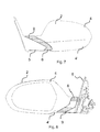
- Fig. 7
- and 8 show an outside mirror for mounting on the mirror triangle
- Fig. 9
- shows a special exterior mirror
- Fig. 10
- shows another example of an exterior mirror
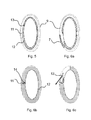
Der Spiegelkopf 2 ist mit Gehäuseabdeckungen 4,4' verschlossen, die ein- oder mehrteilig sein können.The
Das Beispiel aus
In diesem Ausführungsbeispiel kann das Beleuchtungs-Zwischenstück als Blinker oder als Warnanzeige eingesetzt werden. Auch einen Funktion als Sicherheitsleuchte oder Positionsleuchte ist möglich.In this embodiment, the lighting adapter can be used as a turn signal or as a warning display. Also a function as a safety light or position light is possible.
In
Im Schnittbild ist das Lichtfenster 9 zu sehen, das den gesamten unteren Rand der Gehäuseabdeckung abschließt. Hinter dem Lichtfenster 9 ist eine LED 11 angeordnet, die auf einer Gehäuserückwand 13 mit einer Leiterplatte 14 montiert ist. Das Beleuchtungs-Zwischenstück 6 wird als Modul von unten auf die Gehäuseabdeckungen 4, 4' befestigt. Alle Befestigungsarten sind dabei denkbar.In the sectional view, the
Soll der Spiegel keinen Beleuchtungselements aufweisen, wird ein von den Außendimensionen baugleiches Abdeckungsstück 4" montiert. Dieses Abdeckungsstück 4" ist ringförmig ausgebildet. Das Beleuchtungs-Zwischenstück 6 ist von allen Seiten sichtbar und weist eine geschlossene, ellipsoide Außenkontur auf. Das Beleuchtungs-Zwischenstück umfasst einen inneren Hohlraum und ist somit ringförmig ausgebildet. Der Begriff ellipsoide Kontur des Beleuchtungs-Zwischenstücks soll dabei Konturen vom Kreis, über eine Ellipse, sowie gepresste oder gestauchte Ellipsen oder Rechteckstrukturen mit abgeflachten Ecken sowie geschlossene Freiformen, die zu ringförmigen Zwischenstücken führen, umfassen.If the mirror does not have an illumination element, a
Das Beleuchtungs-Zwischenstück 6 wird über einen Kabelbaum, der durch den Hohlniet in das Innere des Spiegelkopfes geführt wird, mit elektrischer Spannung versorgt. Die Kontaktierung wird über Steckverbinder, der am Beleuchtungs-Zwischenstück angebracht ist erreicht. Die untere Abschlusskante 15 ist so ausgebildet, dass sie sich leicht gegen die Spiegelfußabdeckung bewegen kann, aber keinen zu großen Spalt gegen die Spiegelfußabdeckung aufweist, um Probleme mit Windgeräuschen zu vermeiden. Es ist auch möglich die untere Abschlusskante 15 mit einer angespritzten Dichtung zu versehen.The
In einer alternativen Ausführungsform ist das Beleuchtungs-Zwischenstück 6 nicht mit den Bauteilen des schwenkbaren Spiegelkopfes sondern mit der Spiegelfußabdeckung 5 verbunden. Das Beleuchtungs-Zwischenstück wird dann mit einer oberen Abschlusskante 16 ausgebildet, die gegen die Gehäuseabdeckungen 4,4' bewegbar ist. Die elektrische Versorgung in einer solchen Anordnung erfolgt über Abzweige des Kabelbaums im Spiegelfuß oder aber über eine elektrische Verbindung aus dem Spiegelkopf. Soll keine Beleuchtung im Spiegel montiert werden, wird das Beleuchtungs-Zwischenstück 6 durch ein Fuß - Abdeckteil 17, das lediglich aus einem einfachen Ring aus demselben Material wie die Fußabdeckung besteht, ersetzt.In an alternative embodiment, the
Durch das Beleuchtungs-Zwischenstück werden für beleuchtete oder unbeleuchtete Außenspiegel dieselben Gehäuseabdeckungen verwendet und nur entweder das Beleuchtungs-Zwischenstück oder das Abdeckstück mit denselben Außenmaßen eingesetzt.The lighting adapter uses the same housing covers for illuminated or unlit exterior mirrors and only uses either the lighting adapter or cover with the same external dimensions.
Es ist auch die Ausführung mit mehreren Lichtleiterabschnitten denkbar, die jeweils von LEDs mit Licht gespeist werden.It is also conceivable embodiment with multiple light guide sections, which are each fed by LEDs with light.
In einer alternativen Ausführungsform nach
In der Ausführungsform nach
Zwischenstück auf, das zwischen dem Spiegelfuß oder der Spiegelfußabdeckung und dem Spiegelkopf eingeschoben ist.Intermediate piece, which is inserted between the mirror base or the mirror base cover and the mirror head.
Die verwendeten Leuchtmittel sind vorzugsweise LEDs, aber die Erfindung ist nicht auf die Verwendung dieser Leuchtmittel beschränkt. Auch die Verwendung von Glühlampen, EL Folien, OLEDs oder weiteren Entwicklungen von Leuchtmitteln ist umfasst.The bulbs used are preferably LEDs, but the invention is not limited to the use of these bulbs. The use of incandescent lamps, EL films, OLEDs or further developments of lamps is also included.
- 11
- AußenspiegelMirrors
- 22
- Spiegelkopfmirror head
- 33
- Spiegelfußmirror
- 4,4'4,4 '
- Gehäuseabdeckunghousing cover
- 55
- Spiegelfußabdeckungmirror base
- 66
- Beleuchtungs-ZwischenstückLighting adapter
- 77
- Abdeckungcover
- 88th
- Öffnung für SpiegelglasOpening for mirror glass
- 99
- Lichtfensterlight window
- 1010
- Hohlnietrivet
- 1111
- LEDLED
- 1212
- Lichtleiteroptical fiber
- 1313
- GehäuserückwandRear panel
- 1414
- Leiterplattecircuit board
- 1515
- Abschlusskante untenEnd edge down
- 1616
- Abschlusskante obenTop edge at the top
- 1717
- Fuß-AbdeckteilFoot cover
- 1818
- Umlenkoptikdeflecting
Claims (13)
Priority Applications (1)
| Application Number | Priority Date | Filing Date | Title |
|---|---|---|---|
| EP20100194468 EP2463156B1 (en) | 2010-12-10 | 2010-12-10 | Lighting connector |
Applications Claiming Priority (1)
| Application Number | Priority Date | Filing Date | Title |
|---|---|---|---|
| EP20100194468 EP2463156B1 (en) | 2010-12-10 | 2010-12-10 | Lighting connector |
Publications (2)
| Publication Number | Publication Date |
|---|---|
| EP2463156A1 true EP2463156A1 (en) | 2012-06-13 |
| EP2463156B1 EP2463156B1 (en) | 2014-04-16 |
Family
ID=43923781
Family Applications (1)
| Application Number | Title | Priority Date | Filing Date |
|---|---|---|---|
| EP20100194468 Active EP2463156B1 (en) | 2010-12-10 | 2010-12-10 | Lighting connector |
Country Status (1)
| Country | Link |
|---|---|
| EP (1) | EP2463156B1 (en) |
Cited By (1)
| Publication number | Priority date | Publication date | Assignee | Title |
|---|---|---|---|---|
| EP3854635A1 (en) * | 2020-01-21 | 2021-07-28 | Bayerische Motoren Werke Aktiengesellschaft | Rear view mirror for a two-wheeled vehicle |
Citations (9)
| Publication number | Priority date | Publication date | Assignee | Title |
|---|---|---|---|---|
| EP0858932A2 (en) | 1997-02-18 | 1998-08-19 | Reitter & Schefenacker GmbH & Co. KG | Exterior rear view mirror for vehicles, in particular motor vehicles |
| US20040145901A1 (en) * | 2003-01-24 | 2004-07-29 | Rocky Lin | Vehicle rearview mirror assembly with color changing legs |
| DE202006019027U1 (en) * | 2006-12-16 | 2007-02-15 | Bühler, Edmund | External mirror for use in passenger car, has headlight lamp and/or light integrated in housing of mirror, where area of mirror with lamp and light is movably designed relative to mirror surface to serve as headlight for curve illumination |
| US7357549B2 (en) | 2005-09-09 | 2008-04-15 | Fer Fahrzeugelektrik Gmbh | Vehicle lamp |
| EP1914118A2 (en) * | 2006-10-06 | 2008-04-23 | Visiocorp Patents S.à.r.l. | External rear mirror with illumination device |
| EP1923265A2 (en) * | 2006-11-16 | 2008-05-21 | Kawasaki Jukogyo Kabushiki Kaisha | Combined viewing mirror and turn signal lamp for automotive vehicles |
| US20080186723A1 (en) * | 2007-02-05 | 2008-08-07 | Chi-San Huang | Two-sided light-passing device for the additional warning light of an automobile rear-view mirror |
| US7492281B2 (en) | 2005-07-06 | 2009-02-17 | Donnelly Corporation | Vehicle exterior mirror assembly with blind spot indicator |
| US20090073704A1 (en) * | 2007-09-19 | 2009-03-19 | Honda Motor Co., Ltd. | Blinker integrated rear-view mirror of saddle-ride type vehicle |
-
2010
- 2010-12-10 EP EP20100194468 patent/EP2463156B1/en active Active
Patent Citations (9)
| Publication number | Priority date | Publication date | Assignee | Title |
|---|---|---|---|---|
| EP0858932A2 (en) | 1997-02-18 | 1998-08-19 | Reitter & Schefenacker GmbH & Co. KG | Exterior rear view mirror for vehicles, in particular motor vehicles |
| US20040145901A1 (en) * | 2003-01-24 | 2004-07-29 | Rocky Lin | Vehicle rearview mirror assembly with color changing legs |
| US7492281B2 (en) | 2005-07-06 | 2009-02-17 | Donnelly Corporation | Vehicle exterior mirror assembly with blind spot indicator |
| US7357549B2 (en) | 2005-09-09 | 2008-04-15 | Fer Fahrzeugelektrik Gmbh | Vehicle lamp |
| EP1914118A2 (en) * | 2006-10-06 | 2008-04-23 | Visiocorp Patents S.à.r.l. | External rear mirror with illumination device |
| EP1923265A2 (en) * | 2006-11-16 | 2008-05-21 | Kawasaki Jukogyo Kabushiki Kaisha | Combined viewing mirror and turn signal lamp for automotive vehicles |
| DE202006019027U1 (en) * | 2006-12-16 | 2007-02-15 | Bühler, Edmund | External mirror for use in passenger car, has headlight lamp and/or light integrated in housing of mirror, where area of mirror with lamp and light is movably designed relative to mirror surface to serve as headlight for curve illumination |
| US20080186723A1 (en) * | 2007-02-05 | 2008-08-07 | Chi-San Huang | Two-sided light-passing device for the additional warning light of an automobile rear-view mirror |
| US20090073704A1 (en) * | 2007-09-19 | 2009-03-19 | Honda Motor Co., Ltd. | Blinker integrated rear-view mirror of saddle-ride type vehicle |
Cited By (1)
| Publication number | Priority date | Publication date | Assignee | Title |
|---|---|---|---|---|
| EP3854635A1 (en) * | 2020-01-21 | 2021-07-28 | Bayerische Motoren Werke Aktiengesellschaft | Rear view mirror for a two-wheeled vehicle |
Also Published As
| Publication number | Publication date |
|---|---|
| EP2463156B1 (en) | 2014-04-16 |
Similar Documents
| Publication | Publication Date | Title |
|---|---|---|
| EP1914118B1 (en) | External rear mirror with illumination device | |
| EP2762361B1 (en) | Lighting unit | |
| EP1598237B1 (en) | Vehicle exterior mirror | |
| EP1195296A2 (en) | Direction indicating side light | |
| EP1737701A1 (en) | Exterior rearview mirror for vehicles, especially for motor vehicles | |
| WO2005018987A1 (en) | Luminous device for vehicles | |
| WO2020043532A1 (en) | Lighting apparatus for a motor vehicle | |
| EP1160116A2 (en) | Combined instrument for a motor vehicle | |
| DE3803510A1 (en) | Exterior rearview mirror for motor vehicles | |
| DE102019210283A1 (en) | Exterior rear-view mirror arrangement with integrated battery charge indicator function | |
| DE102014104891A1 (en) | License plate lighting device with multiple layers | |
| DE10337615B3 (en) | Lighting device for vehicles | |
| EP2463156B1 (en) | Lighting connector | |
| EP3443188B1 (en) | Motor vehicle lock | |
| DE102010034927A1 (en) | Device for outdoor lighting in rear and lateral region of e.g. motor car during repair purposes, has lighting devices illuminating light, where maximum intensity of emitted light is measured at predefined angle in installed state | |
| WO2016096563A1 (en) | Lighting device for a motor vehicle | |
| EP3814172B1 (en) | Method for producing a blinker module, blinker module, rear-view device, and motor vehicle | |
| EP2500629B1 (en) | Rearview mirror for a vehicle with lighting units with micro-optics | |
| DE102006007884B4 (en) | Luminaire arrangement on a motor vehicle exterior mirror | |
| EP3853518A1 (en) | Light module, in particular for use in a lighting device for a motor vehicle | |
| DE102018208804A1 (en) | Vehicle with encompassing windshield and electrical component between the front pillar and windshield | |
| DE202005018233U1 (en) | Auxiliary light unit for vehicle`s e.g. car, exterior mirror, has backup headlight attached at inner side of indicator and comprising light source that operates only when lighting system and original return headlight are set in operation | |
| DE102011121251A1 (en) | Illuminating module for interior lighting of vehicle part of vehicle i.e. motor car, has lighting component including light entrance and exit surfaces, light source emitted by lighting component, and circuit board fastened to component | |
| DE10347635A1 (en) | Headlights of vehicle, divided in upper and lower part joined to bonnet, to lower part of body, respectively | |
| DE10243491B4 (en) | Side flashing and apron lighting arrangement |
Legal Events
| Date | Code | Title | Description |
|---|---|---|---|
| PUAI | Public reference made under article 153(3) epc to a published international application that has entered the european phase |
Free format text: ORIGINAL CODE: 0009012 |
|
| AK | Designated contracting states |
Kind code of ref document: A1 Designated state(s): AL AT BE BG CH CY CZ DE DK EE ES FI FR GB GR HR HU IE IS IT LI LT LU LV MC MK MT NL NO PL PT RO RS SE SI SK SM TR |
|
| AX | Request for extension of the european patent |
Extension state: BA ME |
|
| 17P | Request for examination filed |
Effective date: 20110802 |
|
| GRAP | Despatch of communication of intention to grant a patent |
Free format text: ORIGINAL CODE: EPIDOSNIGR1 |
|
| INTG | Intention to grant announced |
Effective date: 20131121 |
|
| GRAS | Grant fee paid |
Free format text: ORIGINAL CODE: EPIDOSNIGR3 |
|
| GRAA | (expected) grant |
Free format text: ORIGINAL CODE: 0009210 |
|
| AK | Designated contracting states |
Kind code of ref document: B1 Designated state(s): AL AT BE BG CH CY CZ DE DK EE ES FI FR GB GR HR HU IE IS IT LI LT LU LV MC MK MT NL NO PL PT RO RS SE SI SK SM TR |
|
| REG | Reference to a national code |
Ref country code: GB Ref legal event code: FG4D Free format text: NOT ENGLISH |
|
| REG | Reference to a national code |
Ref country code: CH Ref legal event code: EP |
|
| REG | Reference to a national code |
Ref country code: AT Ref legal event code: REF Ref document number: 662307 Country of ref document: AT Kind code of ref document: T Effective date: 20140515 |
|
| REG | Reference to a national code |
Ref country code: IE Ref legal event code: FG4D Free format text: LANGUAGE OF EP DOCUMENT: GERMAN |
|
| REG | Reference to a national code |
Ref country code: DE Ref legal event code: R096 Ref document number: 502010006659 Country of ref document: DE Effective date: 20140528 |
|
| REG | Reference to a national code |
Ref country code: NL Ref legal event code: VDEP Effective date: 20140416 |
|
| REG | Reference to a national code |
Ref country code: LT Ref legal event code: MG4D |
|
| PG25 | Lapsed in a contracting state [announced via postgrant information from national office to epo] |
Ref country code: GR Free format text: LAPSE BECAUSE OF FAILURE TO SUBMIT A TRANSLATION OF THE DESCRIPTION OR TO PAY THE FEE WITHIN THE PRESCRIBED TIME-LIMIT Effective date: 20140717 Ref country code: NL Free format text: LAPSE BECAUSE OF FAILURE TO SUBMIT A TRANSLATION OF THE DESCRIPTION OR TO PAY THE FEE WITHIN THE PRESCRIBED TIME-LIMIT Effective date: 20140416 Ref country code: IS Free format text: LAPSE BECAUSE OF FAILURE TO SUBMIT A TRANSLATION OF THE DESCRIPTION OR TO PAY THE FEE WITHIN THE PRESCRIBED TIME-LIMIT Effective date: 20140816 Ref country code: BG Free format text: LAPSE BECAUSE OF FAILURE TO SUBMIT A TRANSLATION OF THE DESCRIPTION OR TO PAY THE FEE WITHIN THE PRESCRIBED TIME-LIMIT Effective date: 20140716 Ref country code: LT Free format text: LAPSE BECAUSE OF FAILURE TO SUBMIT A TRANSLATION OF THE DESCRIPTION OR TO PAY THE FEE WITHIN THE PRESCRIBED TIME-LIMIT Effective date: 20140416 Ref country code: FI Free format text: LAPSE BECAUSE OF FAILURE TO SUBMIT A TRANSLATION OF THE DESCRIPTION OR TO PAY THE FEE WITHIN THE PRESCRIBED TIME-LIMIT Effective date: 20140416 Ref country code: NO Free format text: LAPSE BECAUSE OF FAILURE TO SUBMIT A TRANSLATION OF THE DESCRIPTION OR TO PAY THE FEE WITHIN THE PRESCRIBED TIME-LIMIT Effective date: 20140716 Ref country code: CY Free format text: LAPSE BECAUSE OF FAILURE TO SUBMIT A TRANSLATION OF THE DESCRIPTION OR TO PAY THE FEE WITHIN THE PRESCRIBED TIME-LIMIT Effective date: 20140416 |
|
| PG25 | Lapsed in a contracting state [announced via postgrant information from national office to epo] |
Ref country code: HR Free format text: LAPSE BECAUSE OF FAILURE TO SUBMIT A TRANSLATION OF THE DESCRIPTION OR TO PAY THE FEE WITHIN THE PRESCRIBED TIME-LIMIT Effective date: 20140416 Ref country code: SE Free format text: LAPSE BECAUSE OF FAILURE TO SUBMIT A TRANSLATION OF THE DESCRIPTION OR TO PAY THE FEE WITHIN THE PRESCRIBED TIME-LIMIT Effective date: 20140416 Ref country code: RS Free format text: LAPSE BECAUSE OF FAILURE TO SUBMIT A TRANSLATION OF THE DESCRIPTION OR TO PAY THE FEE WITHIN THE PRESCRIBED TIME-LIMIT Effective date: 20140416 Ref country code: LV Free format text: LAPSE BECAUSE OF FAILURE TO SUBMIT A TRANSLATION OF THE DESCRIPTION OR TO PAY THE FEE WITHIN THE PRESCRIBED TIME-LIMIT Effective date: 20140416 Ref country code: ES Free format text: LAPSE BECAUSE OF FAILURE TO SUBMIT A TRANSLATION OF THE DESCRIPTION OR TO PAY THE FEE WITHIN THE PRESCRIBED TIME-LIMIT Effective date: 20140416 Ref country code: PL Free format text: LAPSE BECAUSE OF FAILURE TO SUBMIT A TRANSLATION OF THE DESCRIPTION OR TO PAY THE FEE WITHIN THE PRESCRIBED TIME-LIMIT Effective date: 20140416 |
|
| PG25 | Lapsed in a contracting state [announced via postgrant information from national office to epo] |
Ref country code: PT Free format text: LAPSE BECAUSE OF FAILURE TO SUBMIT A TRANSLATION OF THE DESCRIPTION OR TO PAY THE FEE WITHIN THE PRESCRIBED TIME-LIMIT Effective date: 20140818 |
|
| REG | Reference to a national code |
Ref country code: DE Ref legal event code: R097 Ref document number: 502010006659 Country of ref document: DE |
|
| PG25 | Lapsed in a contracting state [announced via postgrant information from national office to epo] |
Ref country code: SK Free format text: LAPSE BECAUSE OF FAILURE TO SUBMIT A TRANSLATION OF THE DESCRIPTION OR TO PAY THE FEE WITHIN THE PRESCRIBED TIME-LIMIT Effective date: 20140416 Ref country code: RO Free format text: LAPSE BECAUSE OF FAILURE TO SUBMIT A TRANSLATION OF THE DESCRIPTION OR TO PAY THE FEE WITHIN THE PRESCRIBED TIME-LIMIT Effective date: 20140416 Ref country code: EE Free format text: LAPSE BECAUSE OF FAILURE TO SUBMIT A TRANSLATION OF THE DESCRIPTION OR TO PAY THE FEE WITHIN THE PRESCRIBED TIME-LIMIT Effective date: 20140416 Ref country code: DK Free format text: LAPSE BECAUSE OF FAILURE TO SUBMIT A TRANSLATION OF THE DESCRIPTION OR TO PAY THE FEE WITHIN THE PRESCRIBED TIME-LIMIT Effective date: 20140416 Ref country code: CZ Free format text: LAPSE BECAUSE OF FAILURE TO SUBMIT A TRANSLATION OF THE DESCRIPTION OR TO PAY THE FEE WITHIN THE PRESCRIBED TIME-LIMIT Effective date: 20140416 |
|
| PLBE | No opposition filed within time limit |
Free format text: ORIGINAL CODE: 0009261 |
|
| STAA | Information on the status of an ep patent application or granted ep patent |
Free format text: STATUS: NO OPPOSITION FILED WITHIN TIME LIMIT |
|
| 26N | No opposition filed |
Effective date: 20150119 |
|
| PG25 | Lapsed in a contracting state [announced via postgrant information from national office to epo] |
Ref country code: IT Free format text: LAPSE BECAUSE OF FAILURE TO SUBMIT A TRANSLATION OF THE DESCRIPTION OR TO PAY THE FEE WITHIN THE PRESCRIBED TIME-LIMIT Effective date: 20140416 |
|
| REG | Reference to a national code |
Ref country code: DE Ref legal event code: R097 Ref document number: 502010006659 Country of ref document: DE Effective date: 20150119 |
|
| PG25 | Lapsed in a contracting state [announced via postgrant information from national office to epo] |
Ref country code: BE Free format text: LAPSE BECAUSE OF NON-PAYMENT OF DUE FEES Effective date: 20141231 |
|
| PG25 | Lapsed in a contracting state [announced via postgrant information from national office to epo] |
Ref country code: LU Free format text: LAPSE BECAUSE OF FAILURE TO SUBMIT A TRANSLATION OF THE DESCRIPTION OR TO PAY THE FEE WITHIN THE PRESCRIBED TIME-LIMIT Effective date: 20141210 Ref country code: SI Free format text: LAPSE BECAUSE OF FAILURE TO SUBMIT A TRANSLATION OF THE DESCRIPTION OR TO PAY THE FEE WITHIN THE PRESCRIBED TIME-LIMIT Effective date: 20140416 |
|
| REG | Reference to a national code |
Ref country code: CH Ref legal event code: PL |
|
| REG | Reference to a national code |
Ref country code: IE Ref legal event code: MM4A |
|
| PG25 | Lapsed in a contracting state [announced via postgrant information from national office to epo] |
Ref country code: LI Free format text: LAPSE BECAUSE OF NON-PAYMENT OF DUE FEES Effective date: 20141231 Ref country code: CH Free format text: LAPSE BECAUSE OF NON-PAYMENT OF DUE FEES Effective date: 20141231 Ref country code: IE Free format text: LAPSE BECAUSE OF NON-PAYMENT OF DUE FEES Effective date: 20141210 |
|
| REG | Reference to a national code |
Ref country code: FR Ref legal event code: PLFP Year of fee payment: 6 |
|
| PG25 | Lapsed in a contracting state [announced via postgrant information from national office to epo] |
Ref country code: SM Free format text: LAPSE BECAUSE OF FAILURE TO SUBMIT A TRANSLATION OF THE DESCRIPTION OR TO PAY THE FEE WITHIN THE PRESCRIBED TIME-LIMIT Effective date: 20140416 |
|
| PG25 | Lapsed in a contracting state [announced via postgrant information from national office to epo] |
Ref country code: MC Free format text: LAPSE BECAUSE OF FAILURE TO SUBMIT A TRANSLATION OF THE DESCRIPTION OR TO PAY THE FEE WITHIN THE PRESCRIBED TIME-LIMIT Effective date: 20140416 |
|
| PG25 | Lapsed in a contracting state [announced via postgrant information from national office to epo] |
Ref country code: MT Free format text: LAPSE BECAUSE OF FAILURE TO SUBMIT A TRANSLATION OF THE DESCRIPTION OR TO PAY THE FEE WITHIN THE PRESCRIBED TIME-LIMIT Effective date: 20140416 Ref country code: TR Free format text: LAPSE BECAUSE OF FAILURE TO SUBMIT A TRANSLATION OF THE DESCRIPTION OR TO PAY THE FEE WITHIN THE PRESCRIBED TIME-LIMIT Effective date: 20140416 Ref country code: HU Free format text: LAPSE BECAUSE OF FAILURE TO SUBMIT A TRANSLATION OF THE DESCRIPTION OR TO PAY THE FEE WITHIN THE PRESCRIBED TIME-LIMIT; INVALID AB INITIO Effective date: 20101210 |
|
| REG | Reference to a national code |
Ref country code: FR Ref legal event code: PLFP Year of fee payment: 7 |
|
| REG | Reference to a national code |
Ref country code: AT Ref legal event code: MM01 Ref document number: 662307 Country of ref document: AT Kind code of ref document: T Effective date: 20151210 |
|
| PG25 | Lapsed in a contracting state [announced via postgrant information from national office to epo] |
Ref country code: AT Free format text: LAPSE BECAUSE OF NON-PAYMENT OF DUE FEES Effective date: 20151210 |
|
| REG | Reference to a national code |
Ref country code: FR Ref legal event code: PLFP Year of fee payment: 8 |
|
| PG25 | Lapsed in a contracting state [announced via postgrant information from national office to epo] |
Ref country code: MK Free format text: LAPSE BECAUSE OF FAILURE TO SUBMIT A TRANSLATION OF THE DESCRIPTION OR TO PAY THE FEE WITHIN THE PRESCRIBED TIME-LIMIT Effective date: 20140416 |
|
| PG25 | Lapsed in a contracting state [announced via postgrant information from national office to epo] |
Ref country code: AL Free format text: LAPSE BECAUSE OF FAILURE TO SUBMIT A TRANSLATION OF THE DESCRIPTION OR TO PAY THE FEE WITHIN THE PRESCRIBED TIME-LIMIT Effective date: 20140416 |
|
| REG | Reference to a national code |
Ref country code: DE Ref legal event code: R084 Ref document number: 502010006659 Country of ref document: DE |
|
| PGFP | Annual fee paid to national office [announced via postgrant information from national office to epo] |
Ref country code: GB Payment date: 20221223 Year of fee payment: 13 Ref country code: FR Payment date: 20221222 Year of fee payment: 13 |
|
| P01 | Opt-out of the competence of the unified patent court (upc) registered |
Effective date: 20230616 |
|
| PGFP | Annual fee paid to national office [announced via postgrant information from national office to epo] |
Ref country code: DE Payment date: 20231214 Year of fee payment: 14 |