EP2455836A1 - Electronic control for a rotary fluid device - Google Patents
Electronic control for a rotary fluid device Download PDFInfo
- Publication number
- EP2455836A1 EP2455836A1 EP12156078A EP12156078A EP2455836A1 EP 2455836 A1 EP2455836 A1 EP 2455836A1 EP 12156078 A EP12156078 A EP 12156078A EP 12156078 A EP12156078 A EP 12156078A EP 2455836 A1 EP2455836 A1 EP 2455836A1
- Authority
- EP
- European Patent Office
- Prior art keywords
- fluid device
- rotary fluid
- controller
- electric motor
- end portion
- Prior art date
- Legal status (The legal status is an assumption and is not a legal conclusion. Google has not performed a legal analysis and makes no representation as to the accuracy of the status listed.)
- Granted
Links
- 239000012530 fluid Substances 0.000 title claims abstract description 170
- 238000005086 pumping Methods 0.000 claims abstract description 21
- 238000006073 displacement reaction Methods 0.000 claims abstract description 7
- 230000004044 response Effects 0.000 description 5
- 230000001276 controlling effect Effects 0.000 description 3
- 230000007423 decrease Effects 0.000 description 2
- 230000003247 decreasing effect Effects 0.000 description 2
- 230000006870 function Effects 0.000 description 2
- 230000037361 pathway Effects 0.000 description 2
- 238000004804 winding Methods 0.000 description 2
- 230000005672 electromagnetic field Effects 0.000 description 1
- 238000005461 lubrication Methods 0.000 description 1
- 238000007620 mathematical function Methods 0.000 description 1
- 230000001105 regulatory effect Effects 0.000 description 1
- 239000004065 semiconductor Substances 0.000 description 1
Images


Classifications
-
- F—MECHANICAL ENGINEERING; LIGHTING; HEATING; WEAPONS; BLASTING
- F04—POSITIVE - DISPLACEMENT MACHINES FOR LIQUIDS; PUMPS FOR LIQUIDS OR ELASTIC FLUIDS
- F04B—POSITIVE-DISPLACEMENT MACHINES FOR LIQUIDS; PUMPS
- F04B49/00—Control, e.g. of pump delivery, or pump pressure of, or safety measures for, machines, pumps, or pumping installations, not otherwise provided for, or of interest apart from, groups F04B1/00 - F04B47/00
- F04B49/10—Other safety measures
- F04B49/103—Responsive to speed
-
- F—MECHANICAL ENGINEERING; LIGHTING; HEATING; WEAPONS; BLASTING
- F04—POSITIVE - DISPLACEMENT MACHINES FOR LIQUIDS; PUMPS FOR LIQUIDS OR ELASTIC FLUIDS
- F04B—POSITIVE-DISPLACEMENT MACHINES FOR LIQUIDS; PUMPS
- F04B1/00—Multi-cylinder machines or pumps characterised by number or arrangement of cylinders
- F04B1/12—Multi-cylinder machines or pumps characterised by number or arrangement of cylinders having cylinder axes coaxial with, or parallel or inclined to, main shaft axis
- F04B1/26—Control
- F04B1/30—Control of machines or pumps with rotary cylinder blocks
- F04B1/32—Control of machines or pumps with rotary cylinder blocks by varying the relative positions of a swash plate and a cylinder block
- F04B1/328—Control of machines or pumps with rotary cylinder blocks by varying the relative positions of a swash plate and a cylinder block by changing the inclination of the axis of the cylinder barrel relative to the swash plate
-
- F—MECHANICAL ENGINEERING; LIGHTING; HEATING; WEAPONS; BLASTING
- F04—POSITIVE - DISPLACEMENT MACHINES FOR LIQUIDS; PUMPS FOR LIQUIDS OR ELASTIC FLUIDS
- F04B—POSITIVE-DISPLACEMENT MACHINES FOR LIQUIDS; PUMPS
- F04B17/00—Pumps characterised by combination with, or adaptation to, specific driving engines or motors
- F04B17/03—Pumps characterised by combination with, or adaptation to, specific driving engines or motors driven by electric motors
-
- F—MECHANICAL ENGINEERING; LIGHTING; HEATING; WEAPONS; BLASTING
- F04—POSITIVE - DISPLACEMENT MACHINES FOR LIQUIDS; PUMPS FOR LIQUIDS OR ELASTIC FLUIDS
- F04B—POSITIVE-DISPLACEMENT MACHINES FOR LIQUIDS; PUMPS
- F04B49/00—Control, e.g. of pump delivery, or pump pressure of, or safety measures for, machines, pumps, or pumping installations, not otherwise provided for, or of interest apart from, groups F04B1/00 - F04B47/00
- F04B49/06—Control using electricity
- F04B49/065—Control using electricity and making use of computers
-
- F—MECHANICAL ENGINEERING; LIGHTING; HEATING; WEAPONS; BLASTING
- F04—POSITIVE - DISPLACEMENT MACHINES FOR LIQUIDS; PUMPS FOR LIQUIDS OR ELASTIC FLUIDS
- F04B—POSITIVE-DISPLACEMENT MACHINES FOR LIQUIDS; PUMPS
- F04B49/00—Control, e.g. of pump delivery, or pump pressure of, or safety measures for, machines, pumps, or pumping installations, not otherwise provided for, or of interest apart from, groups F04B1/00 - F04B47/00
- F04B49/10—Other safety measures
- F04B49/106—Responsive to pumped volume
-
- F—MECHANICAL ENGINEERING; LIGHTING; HEATING; WEAPONS; BLASTING
- F04—POSITIVE - DISPLACEMENT MACHINES FOR LIQUIDS; PUMPS FOR LIQUIDS OR ELASTIC FLUIDS
- F04B—POSITIVE-DISPLACEMENT MACHINES FOR LIQUIDS; PUMPS
- F04B49/00—Control, e.g. of pump delivery, or pump pressure of, or safety measures for, machines, pumps, or pumping installations, not otherwise provided for, or of interest apart from, groups F04B1/00 - F04B47/00
- F04B49/20—Control, e.g. of pump delivery, or pump pressure of, or safety measures for, machines, pumps, or pumping installations, not otherwise provided for, or of interest apart from, groups F04B1/00 - F04B47/00 by changing the driving speed
-
- F—MECHANICAL ENGINEERING; LIGHTING; HEATING; WEAPONS; BLASTING
- F04—POSITIVE - DISPLACEMENT MACHINES FOR LIQUIDS; PUMPS FOR LIQUIDS OR ELASTIC FLUIDS
- F04B—POSITIVE-DISPLACEMENT MACHINES FOR LIQUIDS; PUMPS
- F04B2203/00—Motor parameters
- F04B2203/02—Motor parameters of rotating electric motors
- F04B2203/0201—Current
-
- F—MECHANICAL ENGINEERING; LIGHTING; HEATING; WEAPONS; BLASTING
- F04—POSITIVE - DISPLACEMENT MACHINES FOR LIQUIDS; PUMPS FOR LIQUIDS OR ELASTIC FLUIDS
- F04B—POSITIVE-DISPLACEMENT MACHINES FOR LIQUIDS; PUMPS
- F04B2203/00—Motor parameters
- F04B2203/02—Motor parameters of rotating electric motors
- F04B2203/0202—Voltage
-
- F—MECHANICAL ENGINEERING; LIGHTING; HEATING; WEAPONS; BLASTING
- F04—POSITIVE - DISPLACEMENT MACHINES FOR LIQUIDS; PUMPS FOR LIQUIDS OR ELASTIC FLUIDS
- F04B—POSITIVE-DISPLACEMENT MACHINES FOR LIQUIDS; PUMPS
- F04B2203/00—Motor parameters
- F04B2203/02—Motor parameters of rotating electric motors
- F04B2203/0209—Rotational speed
Definitions
- Hydraulic systems having hydraulic pumps typically rely on mechanical pressure compensation devices to control torque and/or horsepower output from the hydraulic pump.
- Mechanical pressure compensation devices include yokes, springs, and mechanical valves disposed in the hydraulic system. While such devices are effective for the purpose of controlling torque or horsepower output of the hydraulic pump, such devices add complexity, cost and weight to hydraulic systems. In some applications, the complexity, cost and weight of the hydraulic pump is critical. Therefore, there is a need for a hydraulic system in which the torque or horsepower of a hydraulic pump can be controlled without the need of mechanical pressure compensation devices.
- the present disclosure relates to a fluid device system as it is defined in claim 1.
- the present disclosure relates to a fluid device system having a rotary fluid device.
- the rotary fluid device includes a housing having a main body with a first end portion and an opposite second end portion. The first end portion defines a first chamber and the second end portion defines a second chamber.
- a fixed displacement pumping assembly is disposed in the first chamber of the first end portion.
- An electric motor is disposed in the second chamber of the second end portion. The electric motor includes a shaft that is coupled to the pumping assembly.
- the fluid device system further includes a plurality of sensors that is adapted to sense operating parameters of the rotary fluid device and a controller.
- the controller is in electrical communication with the electric motor of the rotary fluid device and the plurality of sensors.
- the controller includes a microprocessor and a storage media.
- the storage media is in communication with the microprocessor and includes at least one lookup table that includes performance characteristics of the rotary fluid device. The lookup table is used by the controller to achieve a desired attribute of the rotary fluid device.
- FIG. 1 is a schematic representation of a hydraulic system having a fluid device system having exemplary features of aspects in accordance with the principles of the present disclosure.
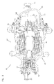
- FIG. 2 is a cross-sectional view of a rotary fluid device suitable for use with the fluid device system of FIG. 1 .
- FIG. 3 is a cross-sectional view of the rotary fluid device taken on line 3-3 of FIG. 2 .
- FIG. 4 is a schematic representation of a controller suitable for use with the fluid device system of FIG. 1 .
- FIG. 5 is an alternate schematic representation of a controller suitable for use with the fluid device system of FIG. 1 .
- the hydraulic system 10 includes a fluid device system, generally designated 12, in fluid communication with a fluid reservoir 14 and an actuator 16 (e.g., motor, cylinder, etc.).
- the fluid device system 12 includes a rotary fluid device, generally designated 18, and a controller, generally designated 20.
- the rotary fluid device 18 includes a fluid pump 22 and an electric motor 24.
- the fluid pump 22 is a fixed displacement type pump that is in engagement with or coupled to the electric motor 24.
- the fluid pump 22 is in fluid communication with the fluid reservoir 14 and the actuator 16. While the fluid pump 22 is shown in direct fluid communication with the fluid reservoir 14 and the actuator 16, it will be understood that the scope of the present disclosure is not limited to the fluid pump 22 being in direct fluid communication with the fluid reservoir 14 and the actuator 16 as any number of valves or other fluid components could be disposed between the fluid pump 22 and the fluid reservoir 14 and/or the actuator 16.
- the electric motor 24 is in electrical communication with the controller 20. As will be described in greater detail subsequently, the controller 20 outputs an electrical signal 25 to the electric motor 24. In response to the electrical signal 25, a shaft 26 of the electric motor 24 rotates. As the fluid pump 22 is a fixed displacement pump and as the fluid pump 22 is in engagement with the shaft 26 of the electric motor 24, the rotation of the shaft 26 causes the fluid pump 22 to transfer fluid from the fluid reservoir 14 to the actuator 16.
- the rotary fluid device 18 includes a housing, generally designated 28.
- the housing 28 includes a fluid inlet 30 and a fluid outlet 32.
- the housing 28 further includes a main body, generally designated 34, which includes a first end portion 36 and an opposite second end portion 38, a first end assembly, generally designated 40, which is adapted for engagement with the first end portion 36 of the main body 34, and a second end assembly, generally designated 42, which is adapted for engagement with the second end portion 38.
- the first end portion 36 of the main body 34 defines a first chamber 44 having a first opening 46 while the second end portion 38 defines a second chamber 48 having a second opening 50.
- the first and second openings 46, 50 are oppositely disposed along a longitudinal axis 52 of the main body 34.
- a passage 54 through the main body 34 connects the first chamber 44 to the second chamber 48.
- the first chamber 44 is adapted to receive the fluid pump 22 through the first opening 46 while the second chamber 48 is adapted to receive the electric motor 24 through the second opening 50.
- the shaft 26 of the electric motor 24 extends through the passage 54 and is engaged with the fluid pump 22.
- a pumping assembly, generally designated 56, is disposed in the first chamber 44 of the main body 34. While the pumping assembly 56 is shown as an axial piston assembly, it will be understood that the scope of the present disclosure is not limited to the pumping assembly 56 being an axial piston assembly as the pumping assembly 56 could be a vane assembly, gerotor assembly, cam lobe assembly, etc. In the subject embodiment, the pumping assembly 56 includes a barrel assembly 58 and an angle block 60.
- the barrel assembly 58 includes a cylinder barrel 62 defining an inner bore.
- the inner bore of the cylinder barrel 62 includes a plurality of internal teeth that are adapted for engagement with the shaft 26.
- the cylinder barrel 62 further defines a plurality of axially oriented cylinder bores 64. Disposed within each cylinder bore 64 is an axially reciprocal piston 66, which includes a generally spherical head that is pivotally received by a slipper member 68. The slipper members 68 slide along an inclined surface of the stationary angle block 60.
- the cylinder bores 64 and the pistons 66 cooperatively define a plurality of volume chambers 70.
- the cylinder barrel 62 rotates about a rotating axis causing the plurality of volume chambers 70 to expand and contract.
- the rotating axis is generally aligned with the longitudinal axis 52.
- the first end assembly 40 is engaged with the first end portion 36 of the main body 34.
- the first end assembly 40 includes a valving portion 72 having an inlet passage 74 and an outlet passage 76 (shown in FIG. 3 ).
- the inlet and outlet passages 74, 76 are arcuately shaped fluid passages.
- the inlet and outlet passages 74, 76 are adapted for commutating fluid communication with the volume chambers 70 of the barrel assembly 58.
- the expanding volume chambers 70 are in fluid communication with the inlet passage 74 while the contracting volume chambers 70 are in fluid communication with the outlet passage 76.
- the inlet passage 74 is in fluid communication with the fluid inlet 30 while the outlet passage 76 is in fluid communication with the fluid outlet 32.
- the fluid outlet 32 is defined by the first end assembly 40.
- the electric motor 24 is disposed in the second chamber 48 of the main body 34.
- the electric motor 24 is a 3-phase brushless DC motor. It will be understood, however, that the scope of the present disclosure is not limited to the electric motor 24 being a 3-phase brushless DC motor.
- the electric motor 24 includes a rotor 80 and a stator 82.
- the rotor 80 includes permanent magnets 84 engaged with the shaft 26.
- the permanent magnets 86 are keyed to the shaft 26 so that the permanent magnets 86 rotate with the shaft 26.
- the stator 82 is engaged with the second end portion 38 of the main body 34.
- the stator 82 includes a plurality of coils that create an electromagnetic field when current passes through the coils. By energizing the coils of the stator 82, the permanent magnets 86 rotate causing the shaft 26 to rotate as well.
- the second end assembly 42 is engaged with the second end portion 38 of the main body 34.
- the second end assembly 42 includes a plate assembly 88 and a cover assembly 90.
- the plate assembly 88 is engaged with the second opening 50 of the second end portion 38 of the main body 34.
- the plate assembly 88 defines a central passage 92 and a plurality of flow passages 94 (shown in FIG. 3 ).
- the central passage 92 is adapted to receive an end portion 96 of the shaft 26.
- a conventional bearing assembly 98 is engaged in the central passage 92 such that an inner race of the bearing assembly 98 is in tight-fit engagement with the shaft 26 while an outer race of the bearing assembly 98 is in tight-fit engagement with the central passage 92.
- the cover assembly 90 defines the fluid inlet 30 for the rotary fluid device 18.
- the cover assembly 90 and the plate assembly cooperatively define a third chamber 100 of the rotary fluid device 18.
- a plurality of sensors 102 is disposed in the third chamber 100.
- the plurality of sensors 102 includes a speed sensor 102a, a position sensor 102b, and a fluid temperature sensor 102c.
- a conventional resolver is used for the speed sensor 102a and the position sensor 102b.
- the resolver includes a stator portion and a rotor portion.
- the stator portion includes a plurality of wire windings through which current flows. As the rotor portion rotates, the relative magnitudes of voltages through the wire windings are measured and used to determine speed and position of the rotor portion.
- the rotor portion is disposed on the end portion 96 of the shaft 26.
- the fluid temperature sensor 102c measures the temperature of the fluid in the rotary fluid device 18.
- the fluid temperature sensor 102c is engaged with the plate assembly 88 and disposed adjacent to one of the plurality of flow passages 94.
- the fluid temperature sensor 102c is a conventional resistance temperature detector (RTD).
- the RTD includes a resistor that changes resistance value as its temperature changes.
- the fluid passes from the second chamber 48 to the first chamber 44 through a fluid pathway 104.
- the fluid pathway 104 is in fluid communication with the inlet passage 74.
- the fluid then enters the expanding volume chamber 70.
- the pistons 66 axially extend and retract from the cylinder bores 64.
- the volume chambers 70 expand thereby drawing fluid from the inlet passage 74 into the expanding volume chambers.
- the volume chambers 70 contract thereby expelling fluid from the contracting volume chambers 70 through the outlet passage 76 and through the fluid outlet 32.
- the controller 20 supplies an electrical signal 25 to the electric motor 24 in order to obtain a desired characteristic (e.g., constant horsepower, pressure compensation, etc.) from the rotary fluid device 18.
- the controller 20 uses a control algorithm and predefined performance data for the electric motor 24 and the fluid pump 22 to control or regulate the rotary fluid device 18.
- the control algorithm is a field oriented control and space vector pulse width modulation control algorithm.
- the rotary fluid device 18 can be controlled to have constant horsepower characteristics or pressure compensation characteristics without the use of typical mechanical pressure compensation devices (e.g., yokes, springs, valves, etc.).
- the controller 20 converts a direct current voltage input to an alternating phase current output, which is supplied to the electric motor 24 for driving the pumping assembly 56.
- the controller 20 includes a plurality of inputs 110.
- the plurality of inputs 110 include a voltage input 110a, a shaft speed input 110b, a shaft position input 110c and a fluid temperature input 110d.
- Voltage is supplied to the controller 20 through the voltage inlet 110a by a power supply.
- the power supply is a DC power supply.
- the speed sensor 102a and the position sensor 102b which are disposed in the third chamber 100 of the rotary fluid device 18, provide information to the controller 20 regarding the speed and position of the shaft 26 through the shaft speed input 110b and the shaft position input 110c.
- the fluid temperature sensor 102c which is disposed in the third chamber 100 of the rotary fluid device 18, provides information to the controller 20 regarding the fluid temperature in the rotary fluid device 18.
- the plurality of sensors 102 provides sensed operating parameters of the rotary fluid device 18 to the controller 20 continuously.
- the plurality of sensors 102 provides sensed operating conditions to the controller 20 on an intermittent basis.
- the plurality of sensors 102 provides sensed operating conditions to the controller 20 when the operating conditions sensed are different than the previously provided operating conditions.
- the controller 20 further includes a plurality of outputs 112 including a voltage output 112a, a phase current output 112b and a phase angle output 112c.
- each of the plurality of outputs 112 is in electrical communication with the electric motor 24.
- the controller 20 further includes a circuit 114 having a microprocessor 116 and a storage media 118.
- the microprocessor 116 is a field programmable gate array (FPGA).
- the FPGA 116 is a semiconductor device having programmable logic components, such as logic gates (e.g., AND, OR, NOT, XOR, etc.) or more complex combinational functions (e.g., decoders, mathematical functions, etc.), and programmable interconnects, which allow the logic blocks to be interconnected.
- the FPGA 116 is programmed to provide voltage and current to the electric motor 24 of the rotary fluid device 18 such that the rotary fluid device 18 responds in accordance with desired performance characteristics (e.g., constant horsepower, pressure compensation, constant speed, etc.).
- desired performance characteristics e.g., constant horsepower, pressure compensation, constant speed, etc.
- the FPGA 116 is a commercially available product from Actel Corporation, which is sold under product identification number A42MX24.
- the storage media 118 can be volatile memory (e.g., RAM), non-volatile memory (e.g., ROM, flash memory, etc.), or a combination of the two. In the subject embodiment, the storage media 118 is non-volatile memory.
- the storage media 118 includes program code for the FPGA 116 and a lookup table 120.
- the lookup table 120 includes performance data for the rotary fluid device 18.
- the lookup table 120 includes a relationship between phase current supplied to the electric motor 24 and the speed of the shaft 26 of the rotary fluid device 18.
- the lookup table 120 accounts for performance losses in the pumping assembly 56 and the electric motor 24. These performance losses include but are not limited to leakage.
- the lookup table 120 further provides a relationship between the phase angle between voltage and current supplied to the electric motor 24 and the torque output of the electric motor 24.
- the lookup table 120 is a multi-dimensional table.
- the variables of the lookup table 120 include phase current supplied to the electric motor 24, phase angle between voltage and current supplied to the electric motor 24, the speed of the shaft 26 of the rotary fluid device 18, torque output of the electric motor 24, and fluid temperature.
- the lookup table 120 includes temperature variables to account for changes in the relationship between phase current and shaft speed and phase angle and torque due to fluctuations in fluid temperature.
- the storage media 118 includes a first lookup table 120a and a second lookup table 120b.
- Each of the first and second lookup tables 120a, 120b provides performance data for the rotary fluid device 18.
- the first lookup table 120a provides a relationship between phase current supplied to the electric motor 24 and the speed of the shaft 26 of the rotary fluid device 18 while the second lookup table 120b provides a relationship between the phase angle between voltage and current supplied to the electric motor 24 and the torque output of the electric motor 24.
- Voltage is supplied to the circuit 114 of the controller 20 from a power source (e.g., battery, generator, etc.).
- a power source e.g., battery, generator, etc.
- the FPGA 116 receives sensed operating parameters of the rotary fluid device 18 from the plurality of sensors 102.
- the sensed operating parameters are received through the plurality of inputs 110.
- the FPGA 116 uses these sensed operating parameters and the lookup table 120 to determine parameters (e.g., voltage, phase current, phase angle, etc.) of the electrical signal 25 that correlate to the desired attribute (e.g., constant horsepower, constant torque, etc.) of the rotary fluid device.
- the controller 20 outputs the electrical single 25 having the determined parameters to the electric motor 24.
- the controller 20 can be used to maintain a generally constant horsepower from the pumping assembly 56 by controlling the voltage and current supplied to the electric motor 24 in response to information provided in the lookup table 120.
- the horsepower (i.e., HP motor-in ) supplied to the electric motor from the controller 20 can be computed by multiplying the voltage from the controller 20 times the current from the controller 20.
- the horsepower out (i.e., HP motor-out ) of the electric motor 24 can be computed by multiplying the horsepower (i.e., HP motor-in ) supplied to the electric motor 24 times the efficiency of the electric motor 24.
- the horsepower out (i.e., HP motor-out ) of the electric motor 24 is generally equal to the horsepower (i.e., HP pump-in ) supplied to the pumping assembly 56.
- the horsepower out (i.e., HP pump-out ) of the pumping assembly 56 can be computed by multiplying the horsepower (i.e., HP pump-in ) supplied to the pumping assembly 56 times the efficiency of the pumping assembly 56. Therefore, in the subject example, the horsepower (i.e., HP out ) out of the rotary fluid device 18 is equal to the voltage supplied by the controller 20 times the current supplied by the controller 20 times the efficiency of the rotary fluid device 18 (i.e., efficiency of the electric motor 24 times the efficiency of the pumping assembly 56).
- the controller 20 receives the efficiency of the rotary fluid device 18 from the lookup table 120 in response to information from at least one of the plurality of inputs 110 of the controller 20. In another embodiment, the controller computes the efficiency of the rotary fluid device 18 from the information provided by the lookup table 120 based on information from at least one of the plurality of inputs 110 of the controller 20. Based on this efficiency, the controller 20 can modify, adjust or regulate the voltage, current and phase angle accordingly to maintain a generally constant horsepower from the rotary fluid device 18.
- the controller 20 can be used as a pressure compensator for the pumping assembly 56 by controlling the voltage and current supplied to the electric motor 24 in response to information provided in the lookup table 120.
- the controller 20 regulates the outlet pressure from the pumping assembly 56 by regulating the speed of the electric motor 24, which controls the flow output of the rotary fluid device 18.
- the controller 20 can determine the torque output of the rotary fluid device 18 by using the lookup table 120. As torque is a function of pressure and displacement of the rotary fluid device 18 and as the displacement of the rotary fluid device 18 is fixed, the controller 20 can determine the pressure of the rotary fluid device 18 based on this torque determination.
- the controller 20 includes a predefined pressure and/or torque upper limit. If the controller 20 determines that the pressure or torque output of the rotary fluid device 18 is exceeding this limit, the controller 20 can reduce the pressure or torque by reducing the speed of the electric motor 24. As the speed of the electric motor 24 decreases, the pressure output from the rotary fluid device 18 also decreases. When the pressure or torque of the rotary fluid device 18 is below the limit, the controller 20 can regulate the speed of the electric motor 24 to maintain the pressure of the rotary fluid device 18.
- the controller 20 includes the predefined pressure and/or torque upper limit and a lower speed threshold. In this embodiment, if the speed of the electric motor 24 is decreased to the lower speed threshold and the pressure and/or torque of the rotary fluid device 18 has not decreased below the upper limit, the controller 20 stops supplying current to the electric motor 24. Once the pressure and/or torque of the rotary fluid device 18 falls below the upper limit, the controller 20 will supply current to the electric motor 24.
- the lookup table 120 for the FPGA 116 is stored in the storage media 118.
- the lookup table 120 provides performance characteristics for the rotary fluid device 18 for a desired operation output (e.g., constant horsepower, pressure compensation, constant speed, etc.). In one embodiment, it may be advantageous to control the rotary fluid device 18 as a constant horsepower device while in another embodiment it may be advantageous to control the rotary fluid device 18 as a pressure compensated device.
- One potential advantage of the fluid device system 12 is that the rotary fluid device 18 can be changed from one desired mode of operation (e.g., constant horsepower) to another desired mode of operation (e.g., pressure compensation) by changing the lookup table 120. In one embodiment, the lookup table 120 can be changed by uploading new lookup table 120 into the storage media 118.
- multiple lookup tables 120 are stored on the storage media 118.
- a user selects which lookup table 120 is used by the controller 20 based on the desired mode of operation of the rotary fluid device 18.
- the controller 20 may be in electrical communication with a multi-position switch. With the switch in a first position, a first lookup table 120 having performance characteristics for the rotary fluid device 18 in constant horsepower mode is used by the controller 20. With the switch in a second position, a second lookup table 120 having performance characteristics for the rotary fluid device 18 in pressure compensation mode is used by the controller 20.
- the switch can be manually or electronically operated.
- the multiple lookup tables 120 are selected based on a sensed parameter of the rotary fluid device 18. For example, in one embodiment, the controller 20 uses the first lookup table 120 if the speed of the shaft 26 of the rotary fluid device 18 is above a certain threshold such as 8,000 rpm while a second lookup table 120 is used if the speed of the shaft 26 of the rotary fluid device 18 is below a certain threshold, such as 8,000 rpm. It will be understood, however, that a single lookup table 120 could incorporate the performance characteristics of the first and second lookup tables 120.
- the multiple lookup tables 120 are selected based on power source to the electric motor 24. For example, if the power being supplied to the electric motor 24 through the controller 24 is from a power source having a limited reserve such as a battery, the controller uses the first lookup table 120 so that the horsepower output of the rotary fluid device 18 is held generally constant in order to conserve energy. If, however, the power being supplied to the electric motor 24 through the controller 24 is from a source having a greater reserve, the controller uses the second lookup table 120.
- the lookup table 120 which includes the performance characteristics of the rotary fluid device 18, can be updated. For example, if the rotary fluid device 18 is replaced or if the rotary fluid device 18 is rebuilt, a new lockup table 120 having the performance characteristics of the replacement or rebuilt rotary fluid device 18 can be uploaded or stored on the storage media 118.
Abstract
Description
- Hydraulic systems having hydraulic pumps, such as axial piston pumps, typically rely on mechanical pressure compensation devices to control torque and/or horsepower output from the hydraulic pump. Mechanical pressure compensation devices include yokes, springs, and mechanical valves disposed in the hydraulic system. While such devices are effective for the purpose of controlling torque or horsepower output of the hydraulic pump, such devices add complexity, cost and weight to hydraulic systems. In some applications, the complexity, cost and weight of the hydraulic pump is critical. Therefore, there is a need for a hydraulic system in which the torque or horsepower of a hydraulic pump can be controlled without the need of mechanical pressure compensation devices.
- The present disclosure relates to a fluid device system as it is defined in
claim 1. - In particular, the present disclosure relates to a fluid device system having a rotary fluid device. The rotary fluid device includes a housing having a main body with a first end portion and an opposite second end portion. The first end portion defines a first chamber and the second end portion defines a second chamber. A fixed displacement pumping assembly is disposed in the first chamber of the first end portion. An electric motor is disposed in the second chamber of the second end portion. The electric motor includes a shaft that is coupled to the pumping assembly. The fluid device system further includes a plurality of sensors that is adapted to sense operating parameters of the rotary fluid device and a controller. The controller is in electrical communication with the electric motor of the rotary fluid device and the plurality of sensors. The controller includes a microprocessor and a storage media. The storage media is in communication with the microprocessor and includes at least one lookup table that includes performance characteristics of the rotary fluid device. The lookup table is used by the controller to achieve a desired attribute of the rotary fluid device.
- A variety of additional aspects will be set forth in the description that follows. These aspects can relate to individual features and to combinations of features. It is to be understood that both the foregoing general description and the following detailed description are exemplary and explanatory only and are not restrictive of the broad concepts upon which the embodiments disclosed herein are based.
-
FIG. 1 is a schematic representation of a hydraulic system having a fluid device system having exemplary features of aspects in accordance with the principles of the present disclosure. -
FIG. 2 is a cross-sectional view of a rotary fluid device suitable for use with the fluid device system ofFIG. 1 . -
FIG. 3 is a cross-sectional view of the rotary fluid device taken on line 3-3 ofFIG. 2 . -
FIG. 4 is a schematic representation of a controller suitable for use with the fluid device system ofFIG. 1 . -
FIG. 5 is an alternate schematic representation of a controller suitable for use with the fluid device system ofFIG. 1 . - Reference will now be made in detail to the exemplary aspects of the present disclosure that are illustrated in the accompanying drawings. Wherever possible, the same reference numbers will be used throughout the drawings to refer to the same or like structure.
- Referring now to
FIG. 1 , a schematic representation of a simplified exemplary hydraulic system, generally designated 10, is shown. Thehydraulic system 10 includes a fluid device system, generally designated 12, in fluid communication with afluid reservoir 14 and an actuator 16 (e.g., motor, cylinder, etc.). Thefluid device system 12 includes a rotary fluid device, generally designated 18, and a controller, generally designated 20. - The
rotary fluid device 18 includes afluid pump 22 and anelectric motor 24. Thefluid pump 22 is a fixed displacement type pump that is in engagement with or coupled to theelectric motor 24. - In the depicted embodiment of
FIG. 1 , thefluid pump 22 is in fluid communication with thefluid reservoir 14 and theactuator 16. While thefluid pump 22 is shown in direct fluid communication with thefluid reservoir 14 and theactuator 16, it will be understood that the scope of the present disclosure is not limited to thefluid pump 22 being in direct fluid communication with thefluid reservoir 14 and theactuator 16 as any number of valves or other fluid components could be disposed between thefluid pump 22 and thefluid reservoir 14 and/or theactuator 16. - In the subject embodiment, the
electric motor 24 is in electrical communication with thecontroller 20. As will be described in greater detail subsequently, thecontroller 20 outputs anelectrical signal 25 to theelectric motor 24. In response to theelectrical signal 25, ashaft 26 of theelectric motor 24 rotates. As thefluid pump 22 is a fixed displacement pump and as thefluid pump 22 is in engagement with theshaft 26 of theelectric motor 24, the rotation of theshaft 26 causes thefluid pump 22 to transfer fluid from thefluid reservoir 14 to theactuator 16. - Referring now to
FIG. 2 , therotary fluid device 18 is shown. Therotary fluid device 18 includes a housing, generally designated 28. Thehousing 28 includes afluid inlet 30 and afluid outlet 32. Thehousing 28 further includes a main body, generally designated 34, which includes afirst end portion 36 and an oppositesecond end portion 38, a first end assembly, generally designated 40, which is adapted for engagement with thefirst end portion 36 of themain body 34, and a second end assembly, generally designated 42, which is adapted for engagement with thesecond end portion 38. - The
first end portion 36 of themain body 34 defines afirst chamber 44 having afirst opening 46 while thesecond end portion 38 defines asecond chamber 48 having asecond opening 50. In the subject embodiment, the first andsecond openings longitudinal axis 52 of themain body 34. Apassage 54 through themain body 34 connects thefirst chamber 44 to thesecond chamber 48. - In the subject embodiment, the
first chamber 44 is adapted to receive thefluid pump 22 through thefirst opening 46 while thesecond chamber 48 is adapted to receive theelectric motor 24 through thesecond opening 50. Theshaft 26 of theelectric motor 24 extends through thepassage 54 and is engaged with thefluid pump 22. - A pumping assembly, generally designated 56, is disposed in the
first chamber 44 of themain body 34. While thepumping assembly 56 is shown as an axial piston assembly, it will be understood that the scope of the present disclosure is not limited to thepumping assembly 56 being an axial piston assembly as thepumping assembly 56 could be a vane assembly, gerotor assembly, cam lobe assembly, etc. In the subject embodiment, thepumping assembly 56 includes abarrel assembly 58 and anangle block 60. - The
barrel assembly 58 includes acylinder barrel 62 defining an inner bore. In the subject embodiment, the inner bore of thecylinder barrel 62 includes a plurality of internal teeth that are adapted for engagement with theshaft 26. - The
cylinder barrel 62 further defines a plurality of axially orientedcylinder bores 64. Disposed within eachcylinder bore 64 is an axiallyreciprocal piston 66, which includes a generally spherical head that is pivotally received by aslipper member 68. Theslipper members 68 slide along an inclined surface of thestationary angle block 60. - The cylinder bores 64 and the
pistons 66 cooperatively define a plurality ofvolume chambers 70. In response to rotation of theshaft 26, thecylinder barrel 62 rotates about a rotating axis causing the plurality ofvolume chambers 70 to expand and contract. In the subject embodiment, the rotating axis is generally aligned with thelongitudinal axis 52. During rotation of thecylinder barrel 62, fluid from a fluid source (e.g., the fluid reservoir 14) is drawn into the expandingvolume chambers 70 while fluid from the contractingvolume chambers 70 is expelled to a fluid destination (e.g., the actuator 16). - The
first end assembly 40 is engaged with thefirst end portion 36 of themain body 34. Thefirst end assembly 40 includes avalving portion 72 having aninlet passage 74 and an outlet passage 76 (shown inFIG. 3 ). In the subject embodiment, the inlet andoutlet passages outlet passages volume chambers 70 of thebarrel assembly 58. The expandingvolume chambers 70 are in fluid communication with theinlet passage 74 while thecontracting volume chambers 70 are in fluid communication with theoutlet passage 76. Theinlet passage 74 is in fluid communication with thefluid inlet 30 while theoutlet passage 76 is in fluid communication with thefluid outlet 32. In the subject embodiment, thefluid outlet 32 is defined by thefirst end assembly 40. - The
electric motor 24 is disposed in thesecond chamber 48 of themain body 34. Theelectric motor 24 is a 3-phase brushless DC motor. It will be understood, however, that the scope of the present disclosure is not limited to theelectric motor 24 being a 3-phase brushless DC motor. Theelectric motor 24 includes arotor 80 and astator 82. - The
rotor 80 includes permanent magnets 84 engaged with theshaft 26. In one embodiment, the permanent magnets 86 are keyed to theshaft 26 so that the permanent magnets 86 rotate with theshaft 26. - The
stator 82 is engaged with thesecond end portion 38 of themain body 34. Thestator 82 includes a plurality of coils that create an electromagnetic field when current passes through the coils. By energizing the coils of thestator 82, the permanent magnets 86 rotate causing theshaft 26 to rotate as well. - The
second end assembly 42 is engaged with thesecond end portion 38 of themain body 34. In the subject embodiment, thesecond end assembly 42 includes aplate assembly 88 and acover assembly 90. - The
plate assembly 88 is engaged with thesecond opening 50 of thesecond end portion 38 of themain body 34. Theplate assembly 88 defines acentral passage 92 and a plurality of flow passages 94 (shown inFIG. 3 ). Thecentral passage 92 is adapted to receive anend portion 96 of theshaft 26. In the subject embodiment, aconventional bearing assembly 98 is engaged in thecentral passage 92 such that an inner race of the bearingassembly 98 is in tight-fit engagement with theshaft 26 while an outer race of the bearingassembly 98 is in tight-fit engagement with thecentral passage 92. - The
cover assembly 90 defines thefluid inlet 30 for therotary fluid device 18. In the subject embodiment, thecover assembly 90 and the plate assembly cooperatively define athird chamber 100 of therotary fluid device 18. - A plurality of sensors 102 is disposed in the
third chamber 100. The plurality of sensors 102 includes aspeed sensor 102a, aposition sensor 102b, and afluid temperature sensor 102c. In the subject embodiment, a conventional resolver is used for thespeed sensor 102a and theposition sensor 102b. The resolver includes a stator portion and a rotor portion. The stator portion includes a plurality of wire windings through which current flows. As the rotor portion rotates, the relative magnitudes of voltages through the wire windings are measured and used to determine speed and position of the rotor portion. In the subject embodiment, the rotor portion is disposed on theend portion 96 of theshaft 26. - The
fluid temperature sensor 102c measures the temperature of the fluid in therotary fluid device 18. In the subject embodiment, thefluid temperature sensor 102c is engaged with theplate assembly 88 and disposed adjacent to one of the plurality offlow passages 94. In a preferred embodiment, thefluid temperature sensor 102c is a conventional resistance temperature detector (RTD). The RTD includes a resistor that changes resistance value as its temperature changes. - Referring now to
FIGS. 2 and3 , the flow of fluid through therotary fluid device 18 will be described. As theshaft 26 of theelectric motor 24 rotates, fluid enters thefluid inlet 30 of thesecond end assembly 42. The fluid enters thethird chamber 100 and passes through theflow passages 94 in theplate assembly 88. The fluid then enters thesecond chamber 48 of themain body 34. In thesecond chamber 48, the fluid is in contact with theelectric motor 24. This fluid contact is potentially advantageous as it provides lubrication to theelectric motor 24. - The fluid passes from the
second chamber 48 to thefirst chamber 44 through afluid pathway 104. Thefluid pathway 104 is in fluid communication with theinlet passage 74. The fluid then enters the expandingvolume chamber 70. As thebarrel assembly 58 rotates about the rotating axis, thepistons 66 axially extend and retract from the cylinder bores 64. As thepistons 66 extend, thevolume chambers 70 expand thereby drawing fluid from theinlet passage 74 into the expanding volume chambers. As thepistons 66 contract, thevolume chambers 70 contract thereby expelling fluid from thecontracting volume chambers 70 through theoutlet passage 76 and through thefluid outlet 32. - Referring now to
FIG. 4 , a schematic representation of thecontroller 20 is shown. Thecontroller 20 supplies anelectrical signal 25 to theelectric motor 24 in order to obtain a desired characteristic (e.g., constant horsepower, pressure compensation, etc.) from therotary fluid device 18. Thecontroller 20 uses a control algorithm and predefined performance data for theelectric motor 24 and thefluid pump 22 to control or regulate therotary fluid device 18. In one embodiment, the control algorithm is a field oriented control and space vector pulse width modulation control algorithm. Through the use of the predefined performance data, therotary fluid device 18 can be controlled to have constant horsepower characteristics or pressure compensation characteristics without the use of typical mechanical pressure compensation devices (e.g., yokes, springs, valves, etc.). - In the subject embodiment, the
controller 20 converts a direct current voltage input to an alternating phase current output, which is supplied to theelectric motor 24 for driving the pumpingassembly 56. Thecontroller 20 includes a plurality of inputs 110. In the subject embodiment, and by way of example only, the plurality of inputs 110 include avoltage input 110a, ashaft speed input 110b, ashaft position input 110c and afluid temperature input 110d. - Voltage is supplied to the
controller 20 through thevoltage inlet 110a by a power supply. In the subject embodiment, the power supply is a DC power supply. Thespeed sensor 102a and theposition sensor 102b, which are disposed in thethird chamber 100 of therotary fluid device 18, provide information to thecontroller 20 regarding the speed and position of theshaft 26 through theshaft speed input 110b and theshaft position input 110c. Thefluid temperature sensor 102c, which is disposed in thethird chamber 100 of therotary fluid device 18, provides information to thecontroller 20 regarding the fluid temperature in therotary fluid device 18. In one embodiment, the plurality of sensors 102 provides sensed operating parameters of therotary fluid device 18 to thecontroller 20 continuously. In another embodiment, the plurality of sensors 102 provides sensed operating conditions to thecontroller 20 on an intermittent basis. In another embodiment, the plurality of sensors 102 provides sensed operating conditions to thecontroller 20 when the operating conditions sensed are different than the previously provided operating conditions. - The
controller 20 further includes a plurality of outputs 112 including avoltage output 112a, a phasecurrent output 112b and aphase angle output 112c. In the subject embodiment, each of the plurality of outputs 112 is in electrical communication with theelectric motor 24. - The
controller 20 further includes acircuit 114 having amicroprocessor 116 and astorage media 118. In the subject embodiment, themicroprocessor 116 is a field programmable gate array (FPGA). TheFPGA 116 is a semiconductor device having programmable logic components, such as logic gates (e.g., AND, OR, NOT, XOR, etc.) or more complex combinational functions (e.g., decoders, mathematical functions, etc.), and programmable interconnects, which allow the logic blocks to be interconnected. In the subject embodiment, theFPGA 116 is programmed to provide voltage and current to theelectric motor 24 of therotary fluid device 18 such that therotary fluid device 18 responds in accordance with desired performance characteristics (e.g., constant horsepower, pressure compensation, constant speed, etc.). In one embodiment, theFPGA 116 is a commercially available product from Actel Corporation, which is sold under product identification number A42MX24. - The
storage media 118 can be volatile memory (e.g., RAM), non-volatile memory (e.g., ROM, flash memory, etc.), or a combination of the two. In the subject embodiment, thestorage media 118 is non-volatile memory. Thestorage media 118 includes program code for theFPGA 116 and a lookup table 120. - In the subject embodiment, the lookup table 120 includes performance data for the
rotary fluid device 18. In one embodiment, and by way of example only, the lookup table 120 includes a relationship between phase current supplied to theelectric motor 24 and the speed of theshaft 26 of therotary fluid device 18. As the lookup table 120 provides performance characteristics of therotary fluid device 18, the lookup table 120 accounts for performance losses in the pumpingassembly 56 and theelectric motor 24. These performance losses include but are not limited to leakage. In the subject embodiment, the lookup table 120 further provides a relationship between the phase angle between voltage and current supplied to theelectric motor 24 and the torque output of theelectric motor 24. - In the subject embodiment, the lookup table 120 is a multi-dimensional table. In the subject embodiment, and by way of example only, the variables of the lookup table 120 include phase current supplied to the
electric motor 24, phase angle between voltage and current supplied to theelectric motor 24, the speed of theshaft 26 of therotary fluid device 18, torque output of theelectric motor 24, and fluid temperature. The lookup table 120 includes temperature variables to account for changes in the relationship between phase current and shaft speed and phase angle and torque due to fluctuations in fluid temperature. - Referring now to
FIG. 5 , an alternate schematic representation of thecontroller 20 is shown. In this alternate embodiment, thestorage media 118 includes a first lookup table 120a and a second lookup table 120b. Each of the first and second lookup tables 120a, 120b provides performance data for therotary fluid device 18. In one embodiment, and by way of example only, the first lookup table 120a provides a relationship between phase current supplied to theelectric motor 24 and the speed of theshaft 26 of therotary fluid device 18 while the second lookup table 120b provides a relationship between the phase angle between voltage and current supplied to theelectric motor 24 and the torque output of theelectric motor 24. - Referring now to
FIGS. 1 and4 , the operation of thefluid device system 12 will be described. Voltage is supplied to thecircuit 114 of thecontroller 20 from a power source (e.g., battery, generator, etc.). With thecircuit 114 in a powered state, theFPGA 116 receives sensed operating parameters of therotary fluid device 18 from the plurality of sensors 102. The sensed operating parameters are received through the plurality of inputs 110. TheFPGA 116 uses these sensed operating parameters and the lookup table 120 to determine parameters (e.g., voltage, phase current, phase angle, etc.) of theelectrical signal 25 that correlate to the desired attribute (e.g., constant horsepower, constant torque, etc.) of the rotary fluid device. Thecontroller 20 outputs the electrical single 25 having the determined parameters to theelectric motor 24. - In one example, the
controller 20 can be used to maintain a generally constant horsepower from the pumpingassembly 56 by controlling the voltage and current supplied to theelectric motor 24 in response to information provided in the lookup table 120. For example, the horsepower (i.e., HPmotor-in) supplied to the electric motor from thecontroller 20 can be computed by multiplying the voltage from thecontroller 20 times the current from thecontroller 20. The horsepower out (i.e., HPmotor-out) of theelectric motor 24 can be computed by multiplying the horsepower (i.e., HPmotor-in) supplied to theelectric motor 24 times the efficiency of theelectric motor 24. In the subject embodiment, the horsepower out (i.e., HPmotor-out) of theelectric motor 24 is generally equal to the horsepower (i.e., HPpump-in) supplied to the pumpingassembly 56. The horsepower out (i.e., HPpump-out) of the pumpingassembly 56 can be computed by multiplying the horsepower (i.e., HPpump-in) supplied to the pumpingassembly 56 times the efficiency of the pumpingassembly 56. Therefore, in the subject example, the horsepower (i.e., HPout) out of therotary fluid device 18 is equal to the voltage supplied by thecontroller 20 times the current supplied by thecontroller 20 times the efficiency of the rotary fluid device 18 (i.e., efficiency of theelectric motor 24 times the efficiency of the pumping assembly 56). In one embodiment, thecontroller 20 receives the efficiency of therotary fluid device 18 from the lookup table 120 in response to information from at least one of the plurality of inputs 110 of thecontroller 20. In another embodiment, the controller computes the efficiency of therotary fluid device 18 from the information provided by the lookup table 120 based on information from at least one of the plurality of inputs 110 of thecontroller 20. Based on this efficiency, thecontroller 20 can modify, adjust or regulate the voltage, current and phase angle accordingly to maintain a generally constant horsepower from therotary fluid device 18. - In another example, the
controller 20 can be used as a pressure compensator for the pumpingassembly 56 by controlling the voltage and current supplied to theelectric motor 24 in response to information provided in the lookup table 120. In the subject embodiment, thecontroller 20 regulates the outlet pressure from the pumpingassembly 56 by regulating the speed of theelectric motor 24, which controls the flow output of therotary fluid device 18. - Knowing the speed of the
shaft 26 of therotary fluid device 18 and the current supplied to theelectric motor 24, thecontroller 20 can determine the torque output of therotary fluid device 18 by using the lookup table 120. As torque is a function of pressure and displacement of therotary fluid device 18 and as the displacement of therotary fluid device 18 is fixed, thecontroller 20 can determine the pressure of therotary fluid device 18 based on this torque determination. - In one embodiment, the
controller 20 includes a predefined pressure and/or torque upper limit. If thecontroller 20 determines that the pressure or torque output of therotary fluid device 18 is exceeding this limit, thecontroller 20 can reduce the pressure or torque by reducing the speed of theelectric motor 24. As the speed of theelectric motor 24 decreases, the pressure output from therotary fluid device 18 also decreases. When the pressure or torque of therotary fluid device 18 is below the limit, thecontroller 20 can regulate the speed of theelectric motor 24 to maintain the pressure of therotary fluid device 18. - In another embodiment, the
controller 20 includes the predefined pressure and/or torque upper limit and a lower speed threshold. In this embodiment, if the speed of theelectric motor 24 is decreased to the lower speed threshold and the pressure and/or torque of therotary fluid device 18 has not decreased below the upper limit, thecontroller 20 stops supplying current to theelectric motor 24. Once the pressure and/or torque of therotary fluid device 18 falls below the upper limit, thecontroller 20 will supply current to theelectric motor 24. - In the subject embodiment, the lookup table 120 for the
FPGA 116 is stored in thestorage media 118. The lookup table 120 provides performance characteristics for therotary fluid device 18 for a desired operation output (e.g., constant horsepower, pressure compensation, constant speed, etc.). In one embodiment, it may be advantageous to control therotary fluid device 18 as a constant horsepower device while in another embodiment it may be advantageous to control therotary fluid device 18 as a pressure compensated device. One potential advantage of thefluid device system 12 is that therotary fluid device 18 can be changed from one desired mode of operation (e.g., constant horsepower) to another desired mode of operation (e.g., pressure compensation) by changing the lookup table 120. In one embodiment, the lookup table 120 can be changed by uploading new lookup table 120 into thestorage media 118. - In another embodiment, multiple lookup tables 120 are stored on the
storage media 118. A user selects which lookup table 120 is used by thecontroller 20 based on the desired mode of operation of therotary fluid device 18. For example, thecontroller 20 may be in electrical communication with a multi-position switch. With the switch in a first position, a first lookup table 120 having performance characteristics for therotary fluid device 18 in constant horsepower mode is used by thecontroller 20. With the switch in a second position, a second lookup table 120 having performance characteristics for therotary fluid device 18 in pressure compensation mode is used by thecontroller 20. The switch can be manually or electronically operated. - In another embodiment, the multiple lookup tables 120 are selected based on a sensed parameter of the
rotary fluid device 18. For example, in one embodiment, thecontroller 20 uses the first lookup table 120 if the speed of theshaft 26 of therotary fluid device 18 is above a certain threshold such as 8,000 rpm while a second lookup table 120 is used if the speed of theshaft 26 of therotary fluid device 18 is below a certain threshold, such as 8,000 rpm. It will be understood, however, that a single lookup table 120 could incorporate the performance characteristics of the first and second lookup tables 120. - In another embodiment, the multiple lookup tables 120 are selected based on power source to the
electric motor 24. For example, if the power being supplied to theelectric motor 24 through thecontroller 24 is from a power source having a limited reserve such as a battery, the controller uses the first lookup table 120 so that the horsepower output of therotary fluid device 18 is held generally constant in order to conserve energy. If, however, the power being supplied to theelectric motor 24 through thecontroller 24 is from a source having a greater reserve, the controller uses the second lookup table 120. - In another embodiment, the lookup table 120, which includes the performance characteristics of the
rotary fluid device 18, can be updated. For example, if therotary fluid device 18 is replaced or if therotary fluid device 18 is rebuilt, a new lockup table 120 having the performance characteristics of the replacement or rebuiltrotary fluid device 18 can be uploaded or stored on thestorage media 118.
Claims (5)
- A fluid device system (12) comprising:a rotary fluid device (18) including:a housing (28) having a main body (34) with a first end portion (36) and an opposite second end portion (38), the first end portion defining a first chamber (44) and the second end portion defining a second chamber (48);a fixed displacement pumping assembly (56) disposed in the first chamber of the first end portion;an electric motor (24) disposed in the second chamber of the second end portion,wherein the electric motor includes a shaft (26) that is coupled to the pumping assembly;a plurality of sensors (102) adapted to sense operating parameters of the rotary fluid device;a controller (20) in electrical communication with the electric motor of the rotary fluid device and the plurality of sensors, the controller including:a microprocessor (116);a storage media (118) in communication with the microprocessor, the storage media having at least one lookup table (120) that includes performance characteristics of the rotary fluid device; andwherein the lookup table is used by the controller to achieve a desired attribute of the rotary fluid device.
- A fluid device system as claimed in claim 1, wherein the desired attribute of the rotary fluid device is generally constant horsepower.
- A fluid device system as claimed in claim 1, wherein the plurality of sensors includes a speed sensor (102a) for sensing the rotational speed of the shaft and a position sensor (102b) for sensing the rotational position of the shaft and a temperature sensor (102c) for sensing temperature of fluid within the rotary fluid device.
- A fluid device system as claimed in claim 1, wherein the lookup table provides a correlation between current supplied to the rotary fluid device and speed of the rotary fluid device.
- A fluid device system as claimed in claim 1, wherein the lookup table provides a correlation between speed of the rotary fluid device, temperature of fluid within the rotary fluid device and a phase angle between voltage and current supplied to the rotary fluid device.
Applications Claiming Priority (2)
| Application Number | Priority Date | Filing Date | Title |
|---|---|---|---|
| US12/181,083 US10100827B2 (en) | 2008-07-28 | 2008-07-28 | Electronic control for a rotary fluid device |
| EP09786073A EP2307937B1 (en) | 2008-07-28 | 2009-07-27 | Electronic control for a rotary fluid device |
Related Parent Applications (1)
| Application Number | Title | Priority Date | Filing Date |
|---|---|---|---|
| EP09786073.8 Division | 2009-07-27 |
Publications (2)
| Publication Number | Publication Date |
|---|---|
| EP2455836A1 true EP2455836A1 (en) | 2012-05-23 |
| EP2455836B1 EP2455836B1 (en) | 2013-08-28 |
Family
ID=41478596
Family Applications (2)
| Application Number | Title | Priority Date | Filing Date |
|---|---|---|---|
| EP12156078.3A Active EP2455836B1 (en) | 2008-07-28 | 2009-07-27 | Electronic control for a rotary fluid device |
| EP09786073A Active EP2307937B1 (en) | 2008-07-28 | 2009-07-27 | Electronic control for a rotary fluid device |
Family Applications After (1)
| Application Number | Title | Priority Date | Filing Date |
|---|---|---|---|
| EP09786073A Active EP2307937B1 (en) | 2008-07-28 | 2009-07-27 | Electronic control for a rotary fluid device |
Country Status (5)
| Country | Link |
|---|---|
| US (1) | US10100827B2 (en) |
| EP (2) | EP2455836B1 (en) |
| CN (1) | CN102165386B (en) |
| AT (1) | ATE550703T1 (en) |
| WO (1) | WO2010013116A2 (en) |
Families Citing this family (66)
| Publication number | Priority date | Publication date | Assignee | Title |
|---|---|---|---|---|
| DE10224750A1 (en) | 2002-06-04 | 2003-12-24 | Fresenius Medical Care De Gmbh | Device for the treatment of a medical fluid |
| CA2767668C (en) | 2009-07-15 | 2017-03-07 | Fresenius Medical Care Holdings, Inc. | Medical fluid cassettes and related systems and methods |
| US9222575B2 (en) * | 2010-12-22 | 2015-12-29 | Gm Global Technology Operations, Llc | Electric pump |
| BRPI1100026A2 (en) * | 2011-01-26 | 2013-04-24 | Whirlpool Sa | reciprocal compressor system and control method |
| US9624915B2 (en) | 2011-03-09 | 2017-04-18 | Fresenius Medical Care Holdings, Inc. | Medical fluid delivery sets and related systems and methods |
| EP3006059B1 (en) | 2011-04-21 | 2017-09-27 | Fresenius Medical Care Holdings, Inc. | Medical fluid pumping systems and related devices and methods |
| US20130089437A1 (en) * | 2011-10-07 | 2013-04-11 | Robert C. Kennedy | Micro-sized fluid metering pump |
| JP5352663B2 (en) * | 2011-12-26 | 2013-11-27 | 株式会社豊田自動織機 | Hydraulic control device for forklift |
| JP5892559B2 (en) * | 2012-02-16 | 2016-03-23 | アルバック機工株式会社 | Pump device |
| WO2013130497A1 (en) * | 2012-02-27 | 2013-09-06 | Magna Powertrain Of America, Inc. | Electric motor -driven pump |
| US9610392B2 (en) | 2012-06-08 | 2017-04-04 | Fresenius Medical Care Holdings, Inc. | Medical fluid cassettes and related systems and methods |
| US9500188B2 (en) * | 2012-06-11 | 2016-11-22 | Fresenius Medical Care Holdings, Inc. | Medical fluid cassettes and related systems and methods |
| JP5835249B2 (en) * | 2013-02-27 | 2015-12-24 | 株式会社豊田自動織機 | Hydraulic control device for forklift |
| JP6269170B2 (en) * | 2013-06-17 | 2018-01-31 | 株式会社豊田自動織機 | Hydraulic drive device for cargo handling vehicle |
| CN104251201B (en) * | 2013-06-28 | 2016-12-28 | 伊顿公司 | The control system of pump based on converter and method and pumping system |
| ES2442640B2 (en) * | 2013-07-31 | 2014-05-21 | Universidad De La Rioja | Regenerative pressure reducing device (DRPR) and operating procedure |
| US20160265520A1 (en) * | 2013-10-29 | 2016-09-15 | Eaton Corporation | Electronic control for a rotary fluid device |
| US10697447B2 (en) * | 2014-08-21 | 2020-06-30 | Fenwal, Inc. | Magnet-based systems and methods for transferring fluid |
| EP3054158A1 (en) | 2015-02-09 | 2016-08-10 | Secop GmbH | Method for stopping a hermetic refrigerant compressor and control system for same |
| CA2996671C (en) | 2015-08-28 | 2023-06-13 | Olitek Pty Ltd | Control system |
| CN108336938B (en) * | 2017-01-19 | 2021-10-22 | 德昌电机(深圳)有限公司 | Pressure control device, system and method |
| USD880530S1 (en) | 2017-05-16 | 2020-04-07 | Enerpac Tool Corp. | Pump |
| US11415119B2 (en) | 2017-05-16 | 2022-08-16 | Enerpac Tool Group Corp. | Hydraulic pump |
| USD890815S1 (en) | 2017-05-16 | 2020-07-21 | Enerpac Tool Group Corp. | Pump |
| US11624326B2 (en) | 2017-05-21 | 2023-04-11 | Bj Energy Solutions, Llc | Methods and systems for supplying fuel to gas turbine engines |
| US11408445B2 (en) | 2018-07-12 | 2022-08-09 | Danfoss Power Solutions Ii Technology A/S | Dual power electro-hydraulic motion control system |
| US11104234B2 (en) | 2018-07-12 | 2021-08-31 | Eaton Intelligent Power Limited | Power architecture for a vehicle such as an off-highway vehicle |
| EP4191077A3 (en) | 2018-11-13 | 2023-09-13 | Enerpac Tool Group Corp. | Hydraulic power system and method for controlling same |
| JP2022519759A (en) | 2019-02-12 | 2022-03-24 | テルッツォ パワー システムズ,エルエルシー | Valveless hydraulic system |
| US11560845B2 (en) | 2019-05-15 | 2023-01-24 | Bj Energy Solutions, Llc | Mobile gas turbine inlet air conditioning system and associated methods |
| US10989180B2 (en) * | 2019-09-13 | 2021-04-27 | Bj Energy Solutions, Llc | Power sources and transmission networks for auxiliary equipment onboard hydraulic fracturing units and associated methods |
| US10815764B1 (en) | 2019-09-13 | 2020-10-27 | Bj Energy Solutions, Llc | Methods and systems for operating a fleet of pumps |
| US10961914B1 (en) | 2019-09-13 | 2021-03-30 | BJ Energy Solutions, LLC Houston | Turbine engine exhaust duct system and methods for noise dampening and attenuation |
| US10895202B1 (en) | 2019-09-13 | 2021-01-19 | Bj Energy Solutions, Llc | Direct drive unit removal system and associated methods |
| US11555756B2 (en) | 2019-09-13 | 2023-01-17 | Bj Energy Solutions, Llc | Fuel, communications, and power connection systems and related methods |
| CA3092829C (en) | 2019-09-13 | 2023-08-15 | Bj Energy Solutions, Llc | Methods and systems for supplying fuel to gas turbine engines |
| CA3092865C (en) | 2019-09-13 | 2023-07-04 | Bj Energy Solutions, Llc | Power sources and transmission networks for auxiliary equipment onboard hydraulic fracturing units and associated methods |
| US11002189B2 (en) | 2019-09-13 | 2021-05-11 | Bj Energy Solutions, Llc | Mobile gas turbine inlet air conditioning system and associated methods |
| US11015536B2 (en) | 2019-09-13 | 2021-05-25 | Bj Energy Solutions, Llc | Methods and systems for supplying fuel to gas turbine engines |
| US11015594B2 (en) | 2019-09-13 | 2021-05-25 | Bj Energy Solutions, Llc | Systems and method for use of single mass flywheel alongside torsional vibration damper assembly for single acting reciprocating pump |
| CA3197583A1 (en) | 2019-09-13 | 2021-03-13 | Bj Energy Solutions, Llc | Fuel, communications, and power connection systems and related methods |
| DE102019214650B3 (en) * | 2019-09-25 | 2020-12-10 | Hanon Systems Efp Deutschland Gmbh | Control unit for pressure regulation |
| JP2021055648A (en) * | 2019-10-01 | 2021-04-08 | 株式会社日立産機システム | Fluid machine device |
| US11708829B2 (en) | 2020-05-12 | 2023-07-25 | Bj Energy Solutions, Llc | Cover for fluid systems and related methods |
| US10968837B1 (en) | 2020-05-14 | 2021-04-06 | Bj Energy Solutions, Llc | Systems and methods utilizing turbine compressor discharge for hydrostatic manifold purge |
| US11428165B2 (en) | 2020-05-15 | 2022-08-30 | Bj Energy Solutions, Llc | Onboard heater of auxiliary systems using exhaust gases and associated methods |
| US11208880B2 (en) | 2020-05-28 | 2021-12-28 | Bj Energy Solutions, Llc | Bi-fuel reciprocating engine to power direct drive turbine fracturing pumps onboard auxiliary systems and related methods |
| US11109508B1 (en) | 2020-06-05 | 2021-08-31 | Bj Energy Solutions, Llc | Enclosure assembly for enhanced cooling of direct drive unit and related methods |
| US11208953B1 (en) | 2020-06-05 | 2021-12-28 | Bj Energy Solutions, Llc | Systems and methods to enhance intake air flow to a gas turbine engine of a hydraulic fracturing unit |
| US10961908B1 (en) | 2020-06-05 | 2021-03-30 | Bj Energy Solutions, Llc | Systems and methods to enhance intake air flow to a gas turbine engine of a hydraulic fracturing unit |
| US11022526B1 (en) | 2020-06-09 | 2021-06-01 | Bj Energy Solutions, Llc | Systems and methods for monitoring a condition of a fracturing component section of a hydraulic fracturing unit |
| US11111768B1 (en) | 2020-06-09 | 2021-09-07 | Bj Energy Solutions, Llc | Drive equipment and methods for mobile fracturing transportation platforms |
| US11066915B1 (en) | 2020-06-09 | 2021-07-20 | Bj Energy Solutions, Llc | Methods for detection and mitigation of well screen out |
| US10954770B1 (en) | 2020-06-09 | 2021-03-23 | Bj Energy Solutions, Llc | Systems and methods for exchanging fracturing components of a hydraulic fracturing unit |
| US11933153B2 (en) | 2020-06-22 | 2024-03-19 | Bj Energy Solutions, Llc | Systems and methods to operate hydraulic fracturing units using automatic flow rate and/or pressure control |
| US11028677B1 (en) | 2020-06-22 | 2021-06-08 | Bj Energy Solutions, Llc | Stage profiles for operations of hydraulic systems and associated methods |
| US11125066B1 (en) | 2020-06-22 | 2021-09-21 | Bj Energy Solutions, Llc | Systems and methods to operate a dual-shaft gas turbine engine for hydraulic fracturing |
| US11939853B2 (en) | 2020-06-22 | 2024-03-26 | Bj Energy Solutions, Llc | Systems and methods providing a configurable staged rate increase function to operate hydraulic fracturing units |
| US11473413B2 (en) | 2020-06-23 | 2022-10-18 | Bj Energy Solutions, Llc | Systems and methods to autonomously operate hydraulic fracturing units |
| US11466680B2 (en) | 2020-06-23 | 2022-10-11 | Bj Energy Solutions, Llc | Systems and methods of utilization of a hydraulic fracturing unit profile to operate hydraulic fracturing units |
| US11220895B1 (en) | 2020-06-24 | 2022-01-11 | Bj Energy Solutions, Llc | Automated diagnostics of electronic instrumentation in a system for fracturing a well and associated methods |
| US11149533B1 (en) | 2020-06-24 | 2021-10-19 | Bj Energy Solutions, Llc | Systems to monitor, detect, and/or intervene relative to cavitation and pulsation events during a hydraulic fracturing operation |
| US11193360B1 (en) | 2020-07-17 | 2021-12-07 | Bj Energy Solutions, Llc | Methods, systems, and devices to enhance fracturing fluid delivery to subsurface formations during high-pressure fracturing operations |
| US11639654B2 (en) | 2021-05-24 | 2023-05-02 | Bj Energy Solutions, Llc | Hydraulic fracturing pumps to enhance flow of fracturing fluid into wellheads and related methods |
| FR3127260A1 (en) | 2021-09-21 | 2023-03-24 | Eaton Intelligent Power Limited | Electronic pressure compensated hydraulic motor pump with variable power output |
| US20230417236A1 (en) * | 2022-06-27 | 2023-12-28 | Hamilton Sundstrand Corporation | Motor driven pump with prognostic health monitoring based on motor characteristics |
Citations (5)
| Publication number | Priority date | Publication date | Assignee | Title |
|---|---|---|---|---|
| US3130902A (en) * | 1961-08-28 | 1964-04-28 | Gen Electric | Refrigerator compressor |
| EP1585205A2 (en) * | 2004-04-09 | 2005-10-12 | A.O. Smith Corporation | Controller for a motor and a method of controlling the motor |
| US20070154321A1 (en) * | 2004-08-26 | 2007-07-05 | Stiles Robert W Jr | Priming protection |
| EP1897439A1 (en) * | 2006-09-01 | 2008-03-12 | Oase GmbH | Water pump for bodies of water containing suspended matter |
| US20100072760A1 (en) * | 2008-04-17 | 2010-03-25 | Levant Power Corporation | Regenerative shock absorber system |
Family Cites Families (38)
| Publication number | Priority date | Publication date | Assignee | Title |
|---|---|---|---|---|
| US4485623A (en) * | 1981-08-10 | 1984-12-04 | Clark Equipment Company | Vehicle hydraulic system with pump speed control |
| JPH0758069B2 (en) * | 1983-09-09 | 1995-06-21 | 株式会社日立製作所 | Compressor motor controller |
| US4794310A (en) * | 1986-04-15 | 1988-12-27 | Siemens Aktiengesellschaft | Phase angle control circuit for motors |
| US4841404A (en) * | 1987-10-07 | 1989-06-20 | Spring Valley Associates, Inc. | Pump and electric motor protector |
| US5677605A (en) * | 1989-08-22 | 1997-10-14 | Unique Mobility, Inc. | Brushless DC motor using phase timing advancement |
| US5216606A (en) * | 1989-12-26 | 1993-06-01 | General Motors Corporation | Compensated control method for filling a fluid-operated automatic transmission clutch |
| US5181837A (en) * | 1991-04-18 | 1993-01-26 | Vickers, Incorporated | Electric motor driven inline hydraulic apparatus |
| DE4120665A1 (en) * | 1991-06-22 | 1992-12-24 | Teves Gmbh Alfred | ELECTRICALLY DRIVEN HYDRAULIC PUMP |
| US5354182A (en) * | 1993-05-17 | 1994-10-11 | Vickers, Incorporated | Unitary electric-motor/hydraulic-pump assembly with noise reduction features |
| US5489831A (en) * | 1993-09-16 | 1996-02-06 | Honeywell Inc. | Pulse width modulating motor controller |
| JP3111790B2 (en) * | 1994-02-03 | 2000-11-27 | 株式会社日立製作所 | Flow control pump |
| US5580221A (en) * | 1994-10-05 | 1996-12-03 | Franklin Electric Co., Inc. | Motor drive circuit for pressure control of a pumping system |
| WO1996028660A1 (en) * | 1995-03-14 | 1996-09-19 | The Boeing Company | Aircraft hydraulic pump control system |
| US5778671A (en) * | 1996-09-13 | 1998-07-14 | Vickers, Inc. | Electrohydraulic system and apparatus with bidirectional electric-motor/hydraulic-pump unit |
| US5905648A (en) * | 1996-11-12 | 1999-05-18 | General Electric Company | Appliance performance control apparatus and method |
| US5915925A (en) * | 1997-01-07 | 1999-06-29 | North, Jr.; Howard L. | Pulseless liquid supply system for flow cytometry |
| US6226582B1 (en) * | 1997-07-21 | 2001-05-01 | Sre Controls, Inc. | Integrated control for electric lift trucks |
| US6045331A (en) * | 1998-08-10 | 2000-04-04 | Gehm; William | Fluid pump speed controller |
| JP3284985B2 (en) * | 1998-12-03 | 2002-05-27 | トヨタ自動車株式会社 | Hydraulic brake device |
| US6176086B1 (en) * | 1998-12-10 | 2001-01-23 | Sauer Inc. | Hydrostatic transmission in one housing |
| JP4493061B2 (en) * | 1999-04-22 | 2010-06-30 | 油研工業株式会社 | Hydraulic pump with built-in electric motor |
| US6264432B1 (en) * | 1999-09-01 | 2001-07-24 | Liquid Metronics Incorporated | Method and apparatus for controlling a pump |
| CA2405739C (en) * | 2000-04-14 | 2006-12-05 | Actuant Corporation | Variable speed hydraulic pump |
| US6688320B2 (en) * | 2000-11-10 | 2004-02-10 | Flowtronex Psi, Inc. | Utility conservation control methodology within a fluid pumping system |
| US6663349B1 (en) * | 2001-03-02 | 2003-12-16 | Reliance Electric Technologies, Llc | System and method for controlling pump cavitation and blockage |
| KR100395207B1 (en) | 2001-03-30 | 2003-08-19 | (주)모토닉 | Control method of brushless direct current motor for fuel supply pump and control apparatus thereof |
| US6484696B2 (en) * | 2001-04-03 | 2002-11-26 | Caterpillar Inc. | Model based rail pressure control for variable displacement pumps |
| AU2003263769A1 (en) * | 2002-07-01 | 2004-01-19 | Xidem, Inc. | Electronically controlled electric motor |
| US6979181B1 (en) * | 2002-11-27 | 2005-12-27 | Aspen Motion Technologies, Inc. | Method for controlling the motor of a pump involving the determination and synchronization of the point of maximum torque with a table of values used to efficiently drive the motor |
| JP2004204872A (en) * | 2002-12-24 | 2004-07-22 | Sankyo Seiki Mfg Co Ltd | Motor controller for flow rate controller |
| US7436139B2 (en) * | 2003-01-29 | 2008-10-14 | Matra Manufacturing & Services Sas | Phase advance angle optimization for brushless motor control |
| US6941785B2 (en) * | 2003-05-13 | 2005-09-13 | Ut-Battelle, Llc | Electric fuel pump condition monitor system using electrical signature analysis |
| US6949908B2 (en) * | 2003-10-06 | 2005-09-27 | Wavecrest Laboratories, Llc | Fault-tolerant electric motor control system |
| US7176648B2 (en) * | 2004-05-18 | 2007-02-13 | Husky Injection Molding Systems Ltd. | Energy management apparatus and method for injection molding systems |
| US7081728B2 (en) * | 2004-08-27 | 2006-07-25 | Sequence Controls Inc. | Apparatus for controlling heat generation and recovery in an induction motor |
| US7096772B2 (en) * | 2004-08-30 | 2006-08-29 | Caterpillar S.A.R.L. | System and method for controlling hydraulic fluid flow |
| DE102005060859A1 (en) | 2005-12-20 | 2007-06-28 | Robert Bosch Gmbh | Method and device for controlling an electric motor |
| US20090087319A1 (en) * | 2007-09-27 | 2009-04-02 | Liquidynamics, Inc. | Pump system including a variable frequency drive controller |
-
2008
- 2008-07-28 US US12/181,083 patent/US10100827B2/en active Active
-
2009
- 2009-07-27 CN CN2009801375543A patent/CN102165386B/en not_active Expired - Fee Related
- 2009-07-27 AT AT09786073T patent/ATE550703T1/en active
- 2009-07-27 EP EP12156078.3A patent/EP2455836B1/en active Active
- 2009-07-27 WO PCT/IB2009/006375 patent/WO2010013116A2/en active Application Filing
- 2009-07-27 EP EP09786073A patent/EP2307937B1/en active Active
Patent Citations (5)
| Publication number | Priority date | Publication date | Assignee | Title |
|---|---|---|---|---|
| US3130902A (en) * | 1961-08-28 | 1964-04-28 | Gen Electric | Refrigerator compressor |
| EP1585205A2 (en) * | 2004-04-09 | 2005-10-12 | A.O. Smith Corporation | Controller for a motor and a method of controlling the motor |
| US20070154321A1 (en) * | 2004-08-26 | 2007-07-05 | Stiles Robert W Jr | Priming protection |
| EP1897439A1 (en) * | 2006-09-01 | 2008-03-12 | Oase GmbH | Water pump for bodies of water containing suspended matter |
| US20100072760A1 (en) * | 2008-04-17 | 2010-03-25 | Levant Power Corporation | Regenerative shock absorber system |
Also Published As
| Publication number | Publication date |
|---|---|
| WO2010013116A2 (en) | 2010-02-04 |
| ATE550703T1 (en) | 2012-04-15 |
| EP2307937B1 (en) | 2012-03-21 |
| CN102165386B (en) | 2013-08-14 |
| US10100827B2 (en) | 2018-10-16 |
| US20100021313A1 (en) | 2010-01-28 |
| WO2010013116A3 (en) | 2010-11-18 |
| EP2455836B1 (en) | 2013-08-28 |
| CN102165386A (en) | 2011-08-24 |
| EP2307937A2 (en) | 2011-04-13 |
Similar Documents
| Publication | Publication Date | Title |
|---|---|---|
| EP2455836B1 (en) | Electronic control for a rotary fluid device | |
| EP3249225B1 (en) | Driving arrangement for a pump or compressor | |
| EP2055945B1 (en) | Method of operating a fluid working machine | |
| US20070253851A1 (en) | Leakage Loss Flow Control | |
| US20080166251A1 (en) | Variable Capacity Gerotor Pump | |
| US20100119383A1 (en) | Pump unit comprising a main pump and a charge pump with a variable pump capacity | |
| JPH08251868A (en) | Electrohydraulic hybrid motor | |
| EP2414680A2 (en) | High pressure variable displacement piston pump | |
| US8834140B2 (en) | Leakage loss flow control and associated media flow delivery assembly | |
| JP3584999B2 (en) | ELECTRO-HYDRAULIC HYBRID MOTOR, ITS CONTROL DEVICE, AND ITS CONTROL METHOD | |
| JP2010121485A (en) | Fuel supply device | |
| WO2015112025A1 (en) | Hydraulic machine valve displacement | |
| US20230102332A1 (en) | Electronic Pressure Compensated Hydraulic Motor Pump with Variable Output Power | |
| US20150211515A1 (en) | Micro-Sized Fluid Metering Pump | |
| WO1997007337A1 (en) | Outlet pressure control for internal gear pump | |
| CN104870820B (en) | Lubricating oil vane pump | |
| KR20170063776A (en) | System to pump fluid and control thereof | |
| JP3608688B2 (en) | Oil pump device | |
| AU2013201632B2 (en) | Driving arrangement for a pump or compressor | |
| JP2012072833A (en) | Discharge rate control device | |
| JPH1073084A (en) | Oil pump device | |
| JP6292105B2 (en) | Pressure regulation system | |
| JP6323308B2 (en) | Relief valve | |
| CN103403360B (en) | For operating the hydraulic means of clutch | |
| CN113309696A (en) | Rotary vane pump |
Legal Events
| Date | Code | Title | Description |
|---|---|---|---|
| PUAI | Public reference made under article 153(3) epc to a published international application that has entered the european phase |
Free format text: ORIGINAL CODE: 0009012 |
|
| 17P | Request for examination filed |
Effective date: 20120217 |
|
| AC | Divisional application: reference to earlier application |
Ref document number: 2307937 Country of ref document: EP Kind code of ref document: P |
|
| AK | Designated contracting states |
Kind code of ref document: A1 Designated state(s): AT BE BG CH CY CZ DE DK EE ES FI FR GB GR HR HU IE IS IT LI LT LU LV MC MK MT NL NO PL PT RO SE SI SK SM TR |
|
| GRAP | Despatch of communication of intention to grant a patent |
Free format text: ORIGINAL CODE: EPIDOSNIGR1 |
|
| RIC1 | Information provided on ipc code assigned before grant |
Ipc: G05D 27/02 20060101ALI20130204BHEP Ipc: G05D 16/20 20060101ALI20130204BHEP Ipc: G05D 7/06 20060101AFI20130204BHEP |
|
| RIN1 | Information on inventor provided before grant (corrected) |
Inventor name: DEVAN, STEPHEN M. Inventor name: WILLIAMS, KEVIN S. Inventor name: GALLOWAY, PHILLIP W. |
|
| GRAS | Grant fee paid |
Free format text: ORIGINAL CODE: EPIDOSNIGR3 |
|
| GRAA | (expected) grant |
Free format text: ORIGINAL CODE: 0009210 |
|
| AC | Divisional application: reference to earlier application |
Ref document number: 2307937 Country of ref document: EP Kind code of ref document: P |
|
| AK | Designated contracting states |
Kind code of ref document: B1 Designated state(s): AT BE BG CH CY CZ DE DK EE ES FI FR GB GR HR HU IE IS IT LI LT LU LV MC MK MT NL NO PL PT RO SE SI SK SM TR |
|
| REG | Reference to a national code |
Ref country code: GB Ref legal event code: FG4D |
|
| REG | Reference to a national code |
Ref country code: CH Ref legal event code: EP |
|
| REG | Reference to a national code |
Ref country code: AT Ref legal event code: REF Ref document number: 629674 Country of ref document: AT Kind code of ref document: T Effective date: 20130915 |
|
| REG | Reference to a national code |
Ref country code: IE Ref legal event code: FG4D |
|
| REG | Reference to a national code |
Ref country code: DE Ref legal event code: R096 Ref document number: 602009018469 Country of ref document: DE Effective date: 20131024 |
|
| REG | Reference to a national code |
Ref country code: AT Ref legal event code: MK05 Ref document number: 629674 Country of ref document: AT Kind code of ref document: T Effective date: 20130828 |
|
| REG | Reference to a national code |
Ref country code: LT Ref legal event code: MG4D |
|
| REG | Reference to a national code |
Ref country code: NL Ref legal event code: VDEP Effective date: 20130828 |
|
| PG25 | Lapsed in a contracting state [announced via postgrant information from national office to epo] |
Ref country code: NO Free format text: LAPSE BECAUSE OF FAILURE TO SUBMIT A TRANSLATION OF THE DESCRIPTION OR TO PAY THE FEE WITHIN THE PRESCRIBED TIME-LIMIT Effective date: 20131128 Ref country code: LT Free format text: LAPSE BECAUSE OF FAILURE TO SUBMIT A TRANSLATION OF THE DESCRIPTION OR TO PAY THE FEE WITHIN THE PRESCRIBED TIME-LIMIT Effective date: 20130828 Ref country code: HR Free format text: LAPSE BECAUSE OF FAILURE TO SUBMIT A TRANSLATION OF THE DESCRIPTION OR TO PAY THE FEE WITHIN THE PRESCRIBED TIME-LIMIT Effective date: 20130828 Ref country code: PT Free format text: LAPSE BECAUSE OF FAILURE TO SUBMIT A TRANSLATION OF THE DESCRIPTION OR TO PAY THE FEE WITHIN THE PRESCRIBED TIME-LIMIT Effective date: 20131230 Ref country code: IS Free format text: LAPSE BECAUSE OF FAILURE TO SUBMIT A TRANSLATION OF THE DESCRIPTION OR TO PAY THE FEE WITHIN THE PRESCRIBED TIME-LIMIT Effective date: 20131228 Ref country code: AT Free format text: LAPSE BECAUSE OF FAILURE TO SUBMIT A TRANSLATION OF THE DESCRIPTION OR TO PAY THE FEE WITHIN THE PRESCRIBED TIME-LIMIT Effective date: 20130828 Ref country code: SE Free format text: LAPSE BECAUSE OF FAILURE TO SUBMIT A TRANSLATION OF THE DESCRIPTION OR TO PAY THE FEE WITHIN THE PRESCRIBED TIME-LIMIT Effective date: 20130828 Ref country code: CY Free format text: LAPSE BECAUSE OF FAILURE TO SUBMIT A TRANSLATION OF THE DESCRIPTION OR TO PAY THE FEE WITHIN THE PRESCRIBED TIME-LIMIT Effective date: 20130828 |
|
| REG | Reference to a national code |
Ref country code: NL Ref legal event code: VDEP Effective date: 20130828 |
|
| PG25 | Lapsed in a contracting state [announced via postgrant information from national office to epo] |
Ref country code: LV Free format text: LAPSE BECAUSE OF FAILURE TO SUBMIT A TRANSLATION OF THE DESCRIPTION OR TO PAY THE FEE WITHIN THE PRESCRIBED TIME-LIMIT Effective date: 20130828 Ref country code: BE Free format text: LAPSE BECAUSE OF FAILURE TO SUBMIT A TRANSLATION OF THE DESCRIPTION OR TO PAY THE FEE WITHIN THE PRESCRIBED TIME-LIMIT Effective date: 20130828 Ref country code: SI Free format text: LAPSE BECAUSE OF FAILURE TO SUBMIT A TRANSLATION OF THE DESCRIPTION OR TO PAY THE FEE WITHIN THE PRESCRIBED TIME-LIMIT Effective date: 20130828 Ref country code: GR Free format text: LAPSE BECAUSE OF FAILURE TO SUBMIT A TRANSLATION OF THE DESCRIPTION OR TO PAY THE FEE WITHIN THE PRESCRIBED TIME-LIMIT Effective date: 20131129 Ref country code: PL Free format text: LAPSE BECAUSE OF FAILURE TO SUBMIT A TRANSLATION OF THE DESCRIPTION OR TO PAY THE FEE WITHIN THE PRESCRIBED TIME-LIMIT Effective date: 20130828 Ref country code: FI Free format text: LAPSE BECAUSE OF FAILURE TO SUBMIT A TRANSLATION OF THE DESCRIPTION OR TO PAY THE FEE WITHIN THE PRESCRIBED TIME-LIMIT Effective date: 20130828 |
|
| PG25 | Lapsed in a contracting state [announced via postgrant information from national office to epo] |
Ref country code: DK Free format text: LAPSE BECAUSE OF FAILURE TO SUBMIT A TRANSLATION OF THE DESCRIPTION OR TO PAY THE FEE WITHIN THE PRESCRIBED TIME-LIMIT Effective date: 20130828 Ref country code: NL Free format text: LAPSE BECAUSE OF FAILURE TO SUBMIT A TRANSLATION OF THE DESCRIPTION OR TO PAY THE FEE WITHIN THE PRESCRIBED TIME-LIMIT Effective date: 20130828 Ref country code: EE Free format text: LAPSE BECAUSE OF FAILURE TO SUBMIT A TRANSLATION OF THE DESCRIPTION OR TO PAY THE FEE WITHIN THE PRESCRIBED TIME-LIMIT Effective date: 20130828 Ref country code: SK Free format text: LAPSE BECAUSE OF FAILURE TO SUBMIT A TRANSLATION OF THE DESCRIPTION OR TO PAY THE FEE WITHIN THE PRESCRIBED TIME-LIMIT Effective date: 20130828 Ref country code: RO Free format text: LAPSE BECAUSE OF FAILURE TO SUBMIT A TRANSLATION OF THE DESCRIPTION OR TO PAY THE FEE WITHIN THE PRESCRIBED TIME-LIMIT Effective date: 20130828 Ref country code: CZ Free format text: LAPSE BECAUSE OF FAILURE TO SUBMIT A TRANSLATION OF THE DESCRIPTION OR TO PAY THE FEE WITHIN THE PRESCRIBED TIME-LIMIT Effective date: 20130828 |
|
| PG25 | Lapsed in a contracting state [announced via postgrant information from national office to epo] |
Ref country code: ES Free format text: LAPSE BECAUSE OF FAILURE TO SUBMIT A TRANSLATION OF THE DESCRIPTION OR TO PAY THE FEE WITHIN THE PRESCRIBED TIME-LIMIT Effective date: 20130828 Ref country code: IT Free format text: LAPSE BECAUSE OF FAILURE TO SUBMIT A TRANSLATION OF THE DESCRIPTION OR TO PAY THE FEE WITHIN THE PRESCRIBED TIME-LIMIT Effective date: 20130828 |
|
| REG | Reference to a national code |
Ref country code: DE Ref legal event code: R097 Ref document number: 602009018469 Country of ref document: DE |
|
| PLBE | No opposition filed within time limit |
Free format text: ORIGINAL CODE: 0009261 |
|
| STAA | Information on the status of an ep patent application or granted ep patent |
Free format text: STATUS: NO OPPOSITION FILED WITHIN TIME LIMIT |
|
| 26N | No opposition filed |
Effective date: 20140530 |
|
| REG | Reference to a national code |
Ref country code: DE Ref legal event code: R097 Ref document number: 602009018469 Country of ref document: DE Effective date: 20140530 |
|
| PG25 | Lapsed in a contracting state [announced via postgrant information from national office to epo] |
Ref country code: LU Free format text: LAPSE BECAUSE OF FAILURE TO SUBMIT A TRANSLATION OF THE DESCRIPTION OR TO PAY THE FEE WITHIN THE PRESCRIBED TIME-LIMIT Effective date: 20140727 |
|
| REG | Reference to a national code |
Ref country code: CH Ref legal event code: PL |
|
| REG | Reference to a national code |
Ref country code: IE Ref legal event code: MM4A |
|
| PG25 | Lapsed in a contracting state [announced via postgrant information from national office to epo] |
Ref country code: CH Free format text: LAPSE BECAUSE OF NON-PAYMENT OF DUE FEES Effective date: 20140731 Ref country code: LI Free format text: LAPSE BECAUSE OF NON-PAYMENT OF DUE FEES Effective date: 20140731 |
|
| PG25 | Lapsed in a contracting state [announced via postgrant information from national office to epo] |
Ref country code: IE Free format text: LAPSE BECAUSE OF NON-PAYMENT OF DUE FEES Effective date: 20140727 |
|
| PG25 | Lapsed in a contracting state [announced via postgrant information from national office to epo] |
Ref country code: SM Free format text: LAPSE BECAUSE OF FAILURE TO SUBMIT A TRANSLATION OF THE DESCRIPTION OR TO PAY THE FEE WITHIN THE PRESCRIBED TIME-LIMIT Effective date: 20130828 Ref country code: MC Free format text: LAPSE BECAUSE OF FAILURE TO SUBMIT A TRANSLATION OF THE DESCRIPTION OR TO PAY THE FEE WITHIN THE PRESCRIBED TIME-LIMIT Effective date: 20130828 |
|
| REG | Reference to a national code |
Ref country code: FR Ref legal event code: PLFP Year of fee payment: 8 |
|
| PG25 | Lapsed in a contracting state [announced via postgrant information from national office to epo] |
Ref country code: MT Free format text: LAPSE BECAUSE OF FAILURE TO SUBMIT A TRANSLATION OF THE DESCRIPTION OR TO PAY THE FEE WITHIN THE PRESCRIBED TIME-LIMIT Effective date: 20130828 Ref country code: BG Free format text: LAPSE BECAUSE OF FAILURE TO SUBMIT A TRANSLATION OF THE DESCRIPTION OR TO PAY THE FEE WITHIN THE PRESCRIBED TIME-LIMIT Effective date: 20130828 |
|
| PG25 | Lapsed in a contracting state [announced via postgrant information from national office to epo] |
Ref country code: TR Free format text: LAPSE BECAUSE OF FAILURE TO SUBMIT A TRANSLATION OF THE DESCRIPTION OR TO PAY THE FEE WITHIN THE PRESCRIBED TIME-LIMIT Effective date: 20130828 Ref country code: HU Free format text: LAPSE BECAUSE OF FAILURE TO SUBMIT A TRANSLATION OF THE DESCRIPTION OR TO PAY THE FEE WITHIN THE PRESCRIBED TIME-LIMIT; INVALID AB INITIO Effective date: 20090727 |
|
| REG | Reference to a national code |
Ref country code: FR Ref legal event code: PLFP Year of fee payment: 9 |
|
| REG | Reference to a national code |
Ref country code: FR Ref legal event code: PLFP Year of fee payment: 10 |
|
| PG25 | Lapsed in a contracting state [announced via postgrant information from national office to epo] |
Ref country code: MK Free format text: LAPSE BECAUSE OF FAILURE TO SUBMIT A TRANSLATION OF THE DESCRIPTION OR TO PAY THE FEE WITHIN THE PRESCRIBED TIME-LIMIT Effective date: 20130828 |
|
| REG | Reference to a national code |
Ref country code: GB Ref legal event code: 732E Free format text: REGISTERED BETWEEN 20181115 AND 20181130 |
|
| REG | Reference to a national code |
Ref country code: DE Ref legal event code: R082 Ref document number: 602009018469 Country of ref document: DE Ref country code: DE Ref legal event code: R081 Ref document number: 602009018469 Country of ref document: DE Owner name: EATON INTELLIGENT POWER LIMITED, IE Free format text: FORMER OWNER: EATON CORP., CLEVELAND, OHIO, US |
|
| P01 | Opt-out of the competence of the unified patent court (upc) registered |
Effective date: 20230521 |
|
| PGFP | Annual fee paid to national office [announced via postgrant information from national office to epo] |
Ref country code: FR Payment date: 20230621 Year of fee payment: 15 |
|
| PGFP | Annual fee paid to national office [announced via postgrant information from national office to epo] |
Ref country code: GB Payment date: 20230620 Year of fee payment: 15 |
|
| PGFP | Annual fee paid to national office [announced via postgrant information from national office to epo] |
Ref country code: DE Payment date: 20230620 Year of fee payment: 15 |