EP2429105A1 - Node in a wireless system and method for time and frequency synchronizing nodes in a wireless system - Google Patents
Node in a wireless system and method for time and frequency synchronizing nodes in a wireless system Download PDFInfo
- Publication number
- EP2429105A1 EP2429105A1 EP10176472A EP10176472A EP2429105A1 EP 2429105 A1 EP2429105 A1 EP 2429105A1 EP 10176472 A EP10176472 A EP 10176472A EP 10176472 A EP10176472 A EP 10176472A EP 2429105 A1 EP2429105 A1 EP 2429105A1
- Authority
- EP
- European Patent Office
- Prior art keywords
- node
- frequency
- slot
- synchronization
- offset
- Prior art date
- Legal status (The legal status is an assumption and is not a legal conclusion. Google has not performed a legal analysis and makes no representation as to the accuracy of the status listed.)
- Granted
Links
- 238000000034 method Methods 0.000 title claims description 31
- 230000005540 biological transmission Effects 0.000 claims abstract description 20
- 238000004891 communication Methods 0.000 claims abstract description 16
- 238000012937 correction Methods 0.000 claims description 11
- 238000004590 computer program Methods 0.000 claims description 10
- 230000008878 coupling Effects 0.000 claims description 6
- 238000010168 coupling process Methods 0.000 claims description 6
- 238000005859 coupling reaction Methods 0.000 claims description 6
- 238000012935 Averaging Methods 0.000 claims description 4
- 230000008859 change Effects 0.000 claims description 4
- 238000013459 approach Methods 0.000 description 26
- 230000006870 function Effects 0.000 description 16
- 238000010586 diagram Methods 0.000 description 8
- 230000001360 synchronised effect Effects 0.000 description 5
- 230000003111 delayed effect Effects 0.000 description 2
- 230000001419 dependent effect Effects 0.000 description 2
- 230000007613 environmental effect Effects 0.000 description 2
- 230000000737 periodic effect Effects 0.000 description 2
- 229920001690 polydopamine Polymers 0.000 description 2
- 230000008569 process Effects 0.000 description 2
- 238000012545 processing Methods 0.000 description 2
- 230000001413 cellular effect Effects 0.000 description 1
- 238000013461 design Methods 0.000 description 1
- 230000003203 everyday effect Effects 0.000 description 1
- 238000001914 filtration Methods 0.000 description 1
- 238000012905 input function Methods 0.000 description 1
- 238000005259 measurement Methods 0.000 description 1
- 238000012986 modification Methods 0.000 description 1
- 230000004048 modification Effects 0.000 description 1
- 238000005070 sampling Methods 0.000 description 1
- 238000012546 transfer Methods 0.000 description 1
Images


Classifications
-
- H—ELECTRICITY
- H04—ELECTRIC COMMUNICATION TECHNIQUE
- H04W—WIRELESS COMMUNICATION NETWORKS
- H04W56/00—Synchronisation arrangements
-
- H—ELECTRICITY
- H04—ELECTRIC COMMUNICATION TECHNIQUE
- H04W—WIRELESS COMMUNICATION NETWORKS
- H04W88/00—Devices specially adapted for wireless communication networks, e.g. terminals, base stations or access point devices
- H04W88/02—Terminal devices
-
- H—ELECTRICITY
- H04—ELECTRIC COMMUNICATION TECHNIQUE
- H04J—MULTIPLEX COMMUNICATION
- H04J3/00—Time-division multiplex systems
- H04J3/02—Details
- H04J3/06—Synchronising arrangements
- H04J3/0635—Clock or time synchronisation in a network
- H04J3/0685—Clock or time synchronisation in a node; Intranode synchronisation
- H04J3/0697—Synchronisation in a packet node
-
- H—ELECTRICITY
- H04—ELECTRIC COMMUNICATION TECHNIQUE
- H04L—TRANSMISSION OF DIGITAL INFORMATION, e.g. TELEGRAPHIC COMMUNICATION
- H04L7/00—Arrangements for synchronising receiver with transmitter
- H04L7/04—Speed or phase control by synchronisation signals
Definitions
- Embodiments of the invention relate to the field of network synchronization, and in particular to the field of decentralized network synchronization. Embodiments of the invention concern the frequency synchronization in such networks.
- wireless communication among electronic devices becomes more and more popular and common.
- One approach for such wireless communication among electronic devices is to organize the devices in an ad hoc network or in a peer-to-peer network, i.e. a decentralized network.
- Fig. 1 shows a schematic representation of an ad hoc network formed by a plurality of wireless devices MS that directly communicate with each other as indicated by the arrows.
- the ad hoc network is set up in such a way that some of the wireless devices MS directly communicate with each other while the communication between distant wireless devices MS like wireless devices 100 and 102 occurs via intermediate wireless devices.
- the wireless devices may be mobile stations or PDAs having a wireless communication capability or any other electronic device allowing for a wireless communication with its environment.
- the wireless devices shown in Fig. 1 are also referred to as the "nodes" of the wireless network.
- nodes form a fully meshed network, which can be true in a wireless network.
- this assumption does not hold for two reasons.
- a node can only communicate with nodes which are within its transmission range, i.e. with neighboring nodes, as mentioned above with regard to Fig. 1 .
- a fully meshed network requires nodes to transmit with very high power, which may not always be possible when nodes are very far apart and also causes high interference, so that that it is preferable to lower transmission power.
- the topology of a wireless network as shown in Fig. 1 is not a fully meshed one.
- Two devices in the network like the electronic devices 100 and 102 are not necessarily within transmission range, but they communicate by using neighboring nodes, thus forming a multi-hop network.
- Time synchronization is defined as aligning local time units in order to define a common slot structure among all nodes.
- the slot synchronization among the respective wireless devices MS is advantageous as it enables synchronous multicast services and coordinated multipoint (CoMP) schemes.
- CoMP coordinated multipoint
- the design of interference management algorithms may be simplified because synchronization is a basic form of coordination.
- the network shown in Fig. 1 can be considered a network of femtocells and each femtocell is typically equipped with a cheap local oscillator having a poor clock quality.
- a clock signal from a macrocell may be difficult to obtain indoors, so that, in accordance with known approaches, the synchronization is performed among the femtocells.
- clock generators and the clocks provided by them are inherently imperfect, i.e. there is no clock that can maintain a perfect track of time and frequency over time. Clock generators and their characteristics thus change over time, however, their characteristics also fluctuate when environmental conditions vary, for example, the temperature. This leads to clock jitter in time and in frequency, so that clocks need to be periodically re-synchronized.
- This known approach applies a biologically inspired technique to perform a decentralized slot synchronization in wireless networks.
- the phase of the clock is updated when a packet is received, based on the detected timing of packets ⁇ ij
- time synchronization is provided so that the also existing frequency offsets of the oscillators used are not addressed.
- Fig. 2 shows, as an example, the transmission slots of three nodes, namely node 1, node 2 and node 3 of a network as is shown in Fig. 1 .
- a network comprises either more or less nodes and the diagram of Fig. 2 is a schematic diagram for discussing the problems of a missing frequency synchronization in such networks.
- the start and duration of a slot are given by the slot clock ⁇ i (t).
- the start of a slot for each node is readjusted.
- the synchronization word S is received periodically, for example, in accordance with one known standard after five slots for readjusting the start of the slots again.
- time synchronization results in a common starting point in time, namely point to at which in each node the first slot starts.
- the duration of the slots is given by the frequency of the local clock generator.
- nodes 1, 2 and 3 have a duration for each slot of T 1 , T 2 and T 3 , respectively.
- the frequencies of the respective clock generators are not synchronized, i.e. each clock generator operates on its own frequency, so that, as can be seen from Fig. 2 , node 1 has a first slot duration T 1 that is longer than the slot duration T 2 of node 2, however, shorter than the slot duration T 3 of node 3.
- the slot of node 2 ends first at time T 1 .
- the slot of node 1 ends second at time T 2 .
- the longest slot is the one of node 3 that ends last at time T 3 .
- the start times of the following slots are no longer aligned, rather, as can be seen they spread over time, i.e. there is an offset of t 2 -t 1 between the start of the second slot of node 2 and the start of the second slot of node 1. Also, there is an offset, of t 3 -t 1 between the start of a second slot of node 2 and a second slot of node 3.
- the maximum offset between the shortest slot, the slot of node 2 and the longest slot, the slot of node 3 is indicated in Fig. 2 as O 1 .
- the slot length varies, that is the start of subsequent slots diverges over time.
- Embodiments of the invention provide a node in a wireless system, the wireless system using transmit/receive slots for a communication among the nodes in the wireless system, the node comprising:
- Embodiments of the invention provide a method for time and frequency synchronizing nodes in a wireless system, the wireless system using transmit/receive slots for a communication among the nodes of the wireless system, the method comprising:
- the clock generator includes a digital oscillator and the slot synchronization block is configured to modify the phase of the clock signal of a digital oscillator by updating the clock generator.
- the clock synchronization block may further be configured to modify the phase of the clock signal of the digital oscillator by delaying incrementing the phase in accordance with the time offset to provide for the time synchronization, and to change a slope of the phase in accordance with the frequency offset to provide for the frequency synchronization.
- the slot synchronization block may be configured to set the slot start of a slot based on the derived time offset every predefined number of slots, and to set the slot start of the other slots based on the derived frequency offset. For example, in accordance with a standard or a protocol time synchronization may occur every five slots, while the frequency synchronization occurs after the first slot, after the second slot, after the third slot and after the fourth slot. In accordance with other standards, a different number of slots may be used, for example, the number may be more than five slots or less than five slots, for example, it may be between 10 and 100.
- the reception block may be configured to derive the frequency offset on the basis of frequency information about the clock generator of the transmitting node in the synchronization signal.
- the synchronization signal may comprise a plurality of portions received subsequently at the node, wherein the reception block may then be configured to derive the frequency offset from the subsequent portions of the synchronization signal.
- the synchronization signal may be a synchronization word and the frequency offset may be derived from the receipt of two subsequent synchronization words at the node.
- the slot synchronization block may be configured to update the clock generator by correcting the frequency of the clock generator by a correction term calculated by an existing correction term and an upgrade function receiving the frequency offset as an input, wherein the input function defines a frequency to which the clock generator and the wireless system converges.
- a computer program product that stores program codes on a machine-readable carrier for performing the inventive method when being executed on a computer on a node of the wireless system.
- embodiments of the invention provide an approach combating clock imperfections due to clocks varying over time and over environmental changes and provide for a synchronization of local oscillators, wherein the frequency synchronization of running local slot clocks in the network is done in a completely decentralized manner by updating the clocks based on local frequency offsets.
- a solution for a decentralized frequency slot synchronization in wireless networks is provided which, in accordance with embodiments, is particularly suited for femtocell networks, where synchronizations through sniffing a macrocell network may be impossible or difficult.
- the approach in accordance with embodiments addresses the above described problems of frequency synchronization of the slot clock which determines the beginning and end of time slotted transmissions.
- the frequency offset that is calculated on the basis of a received signal is used to update the running frequency of an internal slot clock, whereas in accordance with the approach of embodiments of the invention time and frequency synchronization of the slot clocks are performed jointly.
- embodiments of the invention provide a plurality of advantages, e.g.:
- the frequency slot synchronization is performed utilizing the frequency offset obtained from the link-level synchronization to update the clock. Further, the frequency synchronization is performed in a step-by-step manner so that no predefined protocol on the transmission is needed.
- the shape of any updating function can be chosen from a variety of functions, whilst synchronization is still guaranteed.
- the measuring of the frequency of the slot clock can be done based on two consecutive transmissions of the synchronization signal or synchronization word (sync word).
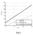
- Fig. 3 illustrating the evolution of a time t of an imperfect clock t i (t) that is subject clock drift (the slope of the clock process) and clock noise.
- the ideal time is shown as line 104.
- the perfect clock of the local oscillator corresponds to the desired time in seconds, e.g. after five seconds also the clock t i (t) indicates five seconds.
- no clock is perfect as a clock timing offset corrupts the time counter and the clock drift corrupts the frequency which requires the periodic synchronization of the oscillator.
- the desired time does not correspond to the time indicated by the clock.
- the oscillator will actually indicate a time between 13 and 14 seconds, and the offset will increase as can be seen from the steeper slope of the lines 106 when compared to line 104.
- the oscillator At a time that should be fifteen seconds after the start the oscillator actually indicates a time of more than 30 seconds.
- Embodiments of the invention avoid such a clock offset and clock drift by the joint time and frequency synchronization.
- the time synchronization adjusts the value of the clock, and in case of a slot synchronization the time is divided into slots of constant length and the nodes, as described above with regard to Fig. 2 , agree on the slot start and slot end, wherein the slot start is synchronized using the sync word.
- the frequency synchronization adjusts the slope of the clock in order to compensate for the clock drift.
- Fig. 4 shows a schematic block diagram of a node in a network as it is for example shown in Fig. 2 .
- the node 200 may be a mobile station of a cellular telephone network, or a PDA device or any other electronic device having wireless capabilities.
- the node 200 comprises an antenna 202 for receiving/transmitting signals between the node 200 and other nodes in the network.
- a switch 204 for example a duplexer is provided for selectively connecting the antenna to either a reception block 206 or to a transmission block 208.
- the switch 204 is controlled by a signal received via a control line 210 that is provided by a slot synchronization block 212.
- the reception block 206 comprises a demodulator 214, a decoder 116 and a synchronization word detector 218.
- the transmission block 208 comprises a frame generator 220 and a modulator 222.
- the slot synchronization block 212 comprises a delay element 224, a local oscillator 226 and a sample/hold-circuit 228.
- the incoming baseband signal from the antenna 202 is passed to the demodulation unit 214 where downconversion, sampling and matched filtering are applied to the signal. Further, the baseband signal is applied to the synchronization word detector 218 that detects a synchronization word, if present, in the baseband signal and derives from the synchronization word the timing and frequency offsets between the transmitting node and the receiving node 200, the timing offset said being denoted by ⁇ ij , and the frequency offset being denoted by ⁇ ij '
- the timing and frequency offsets are applied to the demodulator 214, and the demodulated signal is applied to the decoder 214 decoding the data from the received signal and outputting the data for further processing in other elements of the node which are not depicted in the figure.
- the slot synchronization block 212 comprises the local oscillator 226 providing the slot clock.
- the slot clock is updated on the basis of the detected time and frequency offset ⁇ ij and ⁇ ij .
- the frequency offset ⁇ ij detected by the synchronization word detector 218 is not only applied to the demodulator 214 of the reception block 206 but also to the local oscillator 226 of the slot synchronization block 212.
- the timing offset ⁇ ij detected by the synchronization word detector 218 is not only provided to the demodulator 214 and to the decoder 216 of the reception block 206 but also to the delay element 224 of the slot synchronization block 212.
- a start of a transmission may be delayed by T seconds before a discrete increment of the clock phase is applied.
- the delay element 224 outputs the delay signal to the local oscillator 226 which will be delayed in accordance with the above mentioned rules before putting a signal to the sample/hold-circuit 228 which receives a further input signal indicating whether a transmission mode or a reception mode is desired.
- This signal is applied via the control line Tx/Rx.
- the output signal from the sample/hold-circuit 228 is the control signal on line 210 for switching the switch 204 either to the reception block 206 or to the transmission block 208, thereby connecting the antenna with the respective block.
- the rules for frequency synchronization will be described in further detail below. Based on the slot clock provided by the local oscillator 206 and the Tx/Rx signal coming from a scheduler of the node the transmit and receive slots are determined.
- the transmission block 208 becomes active when data is available for transmission.
- the transmission block 208 receives the data signal via the line data and also a synchronization word via the line sync word.
- the data is multiplexed together with the sync word in the form frame unit 220 wherein, in accordance with embodiments of the invention, the syncword is common to all nodes in the network and is the one that is utilized by the sync word detector 218 in the reception block 206 of a node.
- the transmit frame passes through the modulator unit 222 where it is modulated and upconverted before transmission via the antenna 202.
- known slot synchronization scheme like the ones described in EP 1 852 998 A1 are extended.
- a measured frequency offset is utilized to update the running frequency of the internal slot clock provided by the local oscillator 226 so that in accordance with the approach of embodiments of the invention the frequency synchronization is jointly performed with the time synchronization.
- the drift of the internal clock provided by the local oscillator 226 is denoted as f i (t). This drifts corrupts the ideal internal clock, and by means of the approach of embodiments of the invention the local clocks of all nodes in the network are iteratively updated based on the received signals so that all clocks in the network agree on a common frequency.
- t + denotes a short time instant, for example a time instant 1 ⁇ s after receipt of the packet including the sync word at time t.
- the time difference may be in the range of the increment step of the digital oscillator, i.e. a digital oscillator divides the slot duration T into a number of steps, in the range 100-1000.
- the factor ⁇ is a scalar coupling factor which may be the same for all nodes, and g is an update function.
- averaging function will average all or a subset of the previously derived frequency offsets thereby yielding a convergence towards an average frequency of clock generators in the wireless system.
- the function including the forgetting factor considers only a subset of previously derived frequency offsets. Also, based on this update function nodes in a network converge to the average frequency of all oscillators.
- the update function may be a min/max function selecting for the update of the correction term a minimum or a maximum of the previously derived frequency offsets. This yields a fast convergence towards the frequency of that clock generator in the wireless system that has the minimum frequency or the maximum frequency.
- the scalar coupling factor of the scalar function is used to weigh the update function, wherein the scalar function or scalar coupling factor is selected based on a desired time to convergence or based on a topology of the wireless system.
- the local oscillator as used in the nodes may be digital oscillators as mentioned above, and a slot synchronization block determines the frequency of the clock generator according to the above mentioned equation and sets a slope of a phase signal of the digital oscillator of the clock generator in accordance with the determined frequency.
- the scalar factor ⁇ has a value between 0 and 1, and is selected to trade off between fast convergence ( ⁇ close to 1), and stability of the synchronization ( ⁇ close to 0).
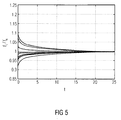
- Fig. 5 shows a diagram showing the evolution over time t of the local frequencies of 15 clocks. As can be seen, due to the approach of embodiments of the invention the frequencies of the local oscillators synchronize quite rapidly.
- Fig. 6 is an illustration similar to Fig. 2 , however, the results of the approach of embodiments of the invention, namely the frequency synchronization, can be seen here.
- a time instance to a synchronization word S is received at the nodes 1, 2 and 3.
- the time offset ⁇ ij , and the frequency offset ⁇ ij are derived as described in Fig.
- At the time to at least the start time of the slots is synchronized on the basis of ⁇ ij
- at the time to only the starting time of the slots may be adjusted, however, in other embodiments at the time to also the frequency may be adjusted on the basis of the derived frequency offset ⁇ ij
- the durations T 1 to T 3 are substantially the same so that the three first slots terminate at time t 1 .
- a frequency synchronization on the basis of the frequency offset derived from the synchronization word S is performed, thereby ensuring that the slot length of the subsequent slot, the respective second slots is also the same for all three nodes or at least substantially the same.
- the frequency synchronization may be performed at the end of each slot/at the beginning of each subsequent slot, i.e. at the instances t 2 , t 3 , t 4 and t 5 .
- the approach of embodiments of the invention is not limited to this scheme, rather dependent on the specifics of the respective nodes and the quality of the local oscillators known from the respective data sheets of the oscillators it may be not necessary to synchronize or update the frequency of a local oscillator in each node 1, 2 and 3 at each instance of time indicated in Fig. 6 . Rather, it may be sufficient to perform the frequency synchronization only every second or in every third slot, for example at time instance t 2 or time instance t 3 provided the stability of the oscillator used in the respective node is sufficient to maintain the constant slot lengths over the required time in accordance with a specified tolerance. Also, different frequency synchronization instances may be applied to different nodes dependent on the quality and the reliability of the oscillators used.
- node 1 may be updated with regard to the frequency every time instance t 1 , t 2 , t 3 , t 4 and t 5 while node 2 is only updated every second instance in time, i.e. at instance t 2 and t 4 .
- node 2 since following instance t 5 a new synchronization word S is received by all nodes, in node 2 only the setting of the start time would be adjusted, however, no frequency synchronization would be done here, as in accordance with the reliability of the local oscillator the next frequency synchronization is deemed to be necessary only at instance t 6 , i.e. following the first slot after having received the second synchronization word in Fig. 6 (not shown).
- Node 3 may comprise an even more reliable local oscillator requiring an update of the frequency or frequency synchronization only after each third slot, i.e. at instant t 3 . Then, in a similar manner as for node 2, upon receiving the following or subsequent synchronization work only the update of the start of the next slot at instance t 5 would be set on the basis of the information derived from the synchronization word, while the next frequency synchronization is done following this next slot, namely at instance t 6 .
- the instances at which a frequency synchronization is required for a node may be controlled dynamically inside the node, for example by determining inside the node a measure indicative of the drift of the local oscillator, for example by comparing the frequency on a regular or periodic basis to determine the drift thereof so that in case a predefined threshold is exceeded at the end of the current slot the frequency synchronization in accordance with the frequency offset information ⁇ ij is done.
- this dynamic approach may be used in each node without providing a predefined and fixed "update interval" for frequency synchronization, rather each node determines the drift of the local oscillator and sets the respective instance in time at which a frequency synchronization is necessary dynamically.
- the frequency offset information may be derived in a receiving node from the synchronization word, for example on the basis of information carried within the synchronization word being indicative of a frequency of the transmitting node. Knowing the time at which the synchronization word was sent the receiving node can determine the frequency offset between its local oscillator and the local oscillator of the transmitting node.
- the sync word may include data indicating the frequency of the oscillator of the transmitting node.
- the synchronization word may comprise two portions or two synchronization words may be received and from the two consecutive words the length of the slots is derived so that the frequency offset can be determined.
- the approach of embodiments of the invention as discussed above is advantageous as it provides for a reliable starting time of each slot in a multi-node wireless communication network wherein the slots have a substantially constant duration so that even after a predetermined number of slots was transmitted/received, i.e. within the interval until the next synchronization word is received, for example every second, all slots terminate at substantially the same instance in time as is shown in Fig. 6 .
- aspects have been described in the context of an apparatus, it is clear that these aspects also represent a description of the corresponding method, where a block or device corresponds to a method step or a feature of a method step. Analogously, aspects described in the context of a method step also represent a description of a corresponding block or item or feature of a corresponding apparatus.
- embodiments of the invention can be implemented in hardware or in software.
- the implementation can be performed using a digital storage medium, for example a floppy disk, a DVD, a CD, a ROM, a PROM, an EPROM, an EEPROM or a FLASH memory, having electronically readable control signals stored thereon, which cooperate (or are capable of cooperating) with a programmable computer system such that the respective method is performed.
- a digital storage medium for example a floppy disk, a DVD, a CD, a ROM, a PROM, an EPROM, an EEPROM or a FLASH memory, having electronically readable control signals stored thereon, which cooperate (or are capable of cooperating) with a programmable computer system such that the respective method is performed.
- Some embodiments according to the invention comprise a data carrier having electronically readable control signals, which are capable of cooperating with a programmable computer system, such that one of the methods described herein is performed.
- embodiments of the present invention can be implemented as a computer program product with a program code, the program code being operative for performing one of the methods when the computer program product runs on a computer.
- the program code may for example be stored on a machine readable carrier.
- inventions comprise the computer program for performing one of the methods described herein, stored on a machine readable carrier.
- an embodiment of the inventive method is, therefore, a computer program having a program code for performing one of the methods described herein, when the computer program runs on a computer.
- a further embodiment of the inventive methods is, therefore, a data carrier (or a digital storage medium, or a computer-readable medium) comprising, recorded thereon, the computer program for performing one of the methods described herein.
- a further embodiment of the inventive method is, therefore, a data stream or a sequence of signals representing the computer program for performing one of the methods described herein.
- the data stream or the sequence of signals may for example be configured to be transferred via a data communication connection, for example via the Internet.
- a further embodiment comprises a processing means, for example a computer, or a programmable logic device, configured to or adapted to perform one of the methods described herein.
- a processing means for example a computer, or a programmable logic device, configured to or adapted to perform one of the methods described herein.
- a further embodiment comprises a computer having installed thereon the computer program for performing one of the methods described herein.
- a programmable logic device for example a field programmable gate array
- a field programmable gate array may cooperate with a microprocessor in order to perform one of the methods described herein.
- the methods are preferably performed by any hardware apparatus.
Abstract
Description
- Embodiments of the invention relate to the field of network synchronization, and in particular to the field of decentralized network synchronization. Embodiments of the invention concern the frequency synchronization in such networks.
- In recent years many everyday items have gained wireless capabilities so that wireless communication among electronic devices becomes more and more popular and common. One approach for such wireless communication among electronic devices is to organize the devices in an ad hoc network or in a peer-to-peer network, i.e. a decentralized network.
-
Fig. 1 shows a schematic representation of an ad hoc network formed by a plurality of wireless devices MS that directly communicate with each other as indicated by the arrows. The ad hoc network is set up in such a way that some of the wireless devices MS directly communicate with each other while the communication between distant wireless devices MS likewireless devices Fig. 1 are also referred to as the "nodes" of the wireless network. - In such a network synchronization of the communication among the respective devices is required. Synchronization schemes known in the art assume that nodes form a fully meshed network, which can be true in a wireless network. However, in general this assumption does not hold for two reasons. First, when considering that nodes are spread over a large area or have low transmission power, a node can only communicate with nodes which are within its transmission range, i.e. with neighboring nodes, as mentioned above with regard to
Fig. 1 . Further, for communications between nodes in a peer-to-peer fashion, a fully meshed network requires nodes to transmit with very high power, which may not always be possible when nodes are very far apart and also causes high interference, so that that it is preferable to lower transmission power. Thus, in many cases the topology of a wireless network as shown inFig. 1 is not a fully meshed one. Two devices in the network, like theelectronic devices - Prior art approaches suggest a time synchronization in such a network in a distributed fashion. Time synchronization is defined as aligning local time units in order to define a common slot structure among all nodes. Basically, the slot synchronization among the respective wireless devices MS is advantageous as it enables synchronous multicast services and coordinated multipoint (CoMP) schemes. Further, the design of interference management algorithms may be simplified because synchronization is a basic form of coordination.
- The network shown in
Fig. 1 can be considered a network of femtocells and each femtocell is typically equipped with a cheap local oscillator having a poor clock quality. A clock signal from a macrocell may be difficult to obtain indoors, so that, in accordance with known approaches, the synchronization is performed among the femtocells. However, clock generators and the clocks provided by them are inherently imperfect, i.e. there is no clock that can maintain a perfect track of time and frequency over time. Clock generators and their characteristics thus change over time, however, their characteristics also fluctuate when environmental conditions vary, for example, the temperature. This leads to clock jitter in time and in frequency, so that clocks need to be periodically re-synchronized. This problem is even more severe in the above described femto networks using low-quality clock generators the characteristics of which will change more rapidly than the characteristics of high-quality clock generators. However, it has to be mentioned even in case of high-quality clock generators that there is no perfect clock. - In the art various forms of network synchronizations have been proposed, which typically rely on a master-slave type of architecture. A master clock dictates its timing and frequency to the slave clock. This solution requires a very high clock quality for the master, however, is prone to single points of failure because the slave clock completely depends on the master clock.
- An alternative known approach is to perform synchronization in a decentralized manner. In such a scenario each node updates its clock based on the detected neighboring clock and in return it influences also its neighbors. Therefore, in such approaches local update rules need to be designed that lead to the synchronization of the network. Decentralized network synchronization solutions have been proposed. Based on the theory of pulse-covered oscillators, a solution described by Tyrrell, A.; Auer, G. and Bettstetter, C. an "Emergent Slot Synchronization in Wireless Networks", IEEE Transactions on Mobile Computing, 2010, vol. 9, pp. 719-732, and also described in
EP 1 852 998 A1 - Another known solution is described by Ebner, A.; Rohling, H.; Halfmann, R. and Lott, M. "Synchronization in ad hoc networks based on UTRA TTD" Proceedings IEEE International Symposium on Personal, Indoor and Mobile Radio Communications (PIMRC), 2002. This approach is targeted at UMTS vehicular communications, however, it requires to first perform a time synchronization before performing the task of frequency synchronization. More specifically, in a first step a coarse or one-shot time synchronization is performed using GPS (GPS=Global Positioning System). Following this, a fine time synchronization is performed. Only once these two steps for time synchronization are completed a coarse frequency synchronization followed by a fine frequency synchronization is carried out. However, this approach requires to first perform the time synchronization before performing the frequency synchronization, that is without the first step this approach cannot cope with any initial timing misalignment. In addition, time synchronization is performed using GPS which is not available indoor for femtocells. Further, using the GPS approach already guarantees a time synchronization precision of microseconds that can also be used for frequency synchronization as GPS clocks are very accurate, as is described by Lewandowski, W.; Petit, G. and Thomas, C. "Precision and accuracy of GPS time transfer" IEEE Transactions on Instrumentation and Measurement, 1993, vol. 42, pp. 474-479.
- With regard to
Fig. 2 , the problems of a missing frequency synchronization in decentralized networks as is, for example, shown inFig. 1 , will be explained in further detail.Fig. 2 shows, as an example, the transmission slots of three nodes, namelynode 1,node 2 andnode 3 of a network as is shown inFig. 1 . Naturally, such a network comprises either more or less nodes and the diagram ofFig. 2 is a schematic diagram for discussing the problems of a missing frequency synchronization in such networks. In the nodes the start and duration of a slot are given by the slot clock φi(t). Upon receiving a synchronization word the start time of a slot at which φi(t)=0 is set to the same point of time in all nodes, and the duration of a slot within a node is given by the clock generator frequency that is defined as InFig. 2 , at time to a synchronization word S is received at each ofnodes nodes Fig. 2 ,node 1 has a first slot duration T1 that is longer than the slot duration T2 ofnode 2, however, shorter than the slot duration T3 ofnode 3. Thus, the slot ofnode 2 ends first at time T1. The slot ofnode 1 ends second at time T2. The longest slot is the one ofnode 3 that ends last at time T3. Thus, following the receipt of the time synchronization S after the first slot, the start times of the following slots are no longer aligned, rather, as can be seen they spread over time, i.e. there is an offset of t2-t1 between the start of the second slot ofnode 2 and the start of the second slot ofnode 1. Also, there is an offset, of t3-t1 between the start of a second slot ofnode 2 and a second slot ofnode 3. The maximum offset between the shortest slot, the slot ofnode 2 and the longest slot, the slot ofnode 3 is indicated inFig. 2 as O1. Due to this offset between the respective nodes, the starting times of the subsequent slots are no longer aligned, so that without frequency synchronization the spread in slot starts increases over time. This can be seen fromFig. 2 showing the offset between the shortest slot, the slot ofnode 2 and the longest slot, the slot ofnode 3, after five slots. This is indicated inFig. 2 at O2. As can be seen, this offset increases dramatically. Actually, in thisscenario node 2 already processed five slots whilenode 3 only processed four slots. - Thus, in case the nodes are not frequency synchronized, the slot length varies, that is the start of subsequent slots diverges over time.
- It is an object of the invention to provide an improved synchronization scheme for a wireless network reducing or avoiding slot length variations among slots of nodes in wireless networks.
- This object is achieved by a node in accordance with
claim 1 and by a method in accordance with claim 11. - Embodiments of the invention provide a node in a wireless system, the wireless system using transmit/receive slots for a communication among the nodes in the wireless system, the node comprising:
- a reception block, the reception block being configured to receive from a transmitting node in the wireless system a synchronization signal, and to derive from the synchronization signal a time offset and a frequency offset, between clock generators in the node and in the transmitting node;
- a slot synchronization block including the clock generator, the slot synchronization block being configured to update the clock generator based on the derived time offset and the derived frequency offset, and
- a transmission block configured to transmit data,
- wherein the slot synchronization block is configured to set a slot start of a slot based on the derived offset and to set a slot start of a subsequent slot based on the derived frequency offset.
- Embodiments of the invention provide a method for time and frequency synchronizing nodes in a wireless system, the wireless system using transmit/receive slots for a communication among the nodes of the wireless system, the method comprising:
- receiving at a receiving node from a transmitting node in the wireless system a synchronization signal;
- deriving from the synchronization signal a time offset and a frequency offset between clock generators in the receiving node and in the transmitting node; and
- updating the clock generator of the receiving node based on the derived time offset and the derived frequency offset,
- wherein a slot start of a slot is set based on the derived time offset, and a slot start of a subsequent slot is set based on the derived frequency offset.
- In accordance with embodiments, the clock generator includes a digital oscillator and the slot synchronization block is configured to modify the phase of the clock signal of a digital oscillator by updating the clock generator. In such an embodiment the clock synchronization block may further be configured to modify the phase of the clock signal of the digital oscillator by delaying incrementing the phase in accordance with the time offset to provide for the time synchronization, and to change a slope of the phase in accordance with the frequency offset to provide for the frequency synchronization.
- In accordance with embodiments of the invention, the slot synchronization block may be configured to set the slot start of a slot based on the derived time offset every predefined number of slots, and to set the slot start of the other slots based on the derived frequency offset. For example, in accordance with a standard or a protocol time synchronization may occur every five slots, while the frequency synchronization occurs after the first slot, after the second slot, after the third slot and after the fourth slot. In accordance with other standards, a different number of slots may be used, for example, the number may be more than five slots or less than five slots, for example, it may be between 10 and 100.
- In accordance with further embodiments, the reception block may be configured to derive the frequency offset on the basis of frequency information about the clock generator of the transmitting node in the synchronization signal.
- In accordance with another embodiment the synchronization signal may comprise a plurality of portions received subsequently at the node, wherein the reception block may then be configured to derive the frequency offset from the subsequent portions of the synchronization signal. The synchronization signal may be a synchronization word and the frequency offset may be derived from the receipt of two subsequent synchronization words at the node.
- In accordance with another embodiment of the invention the slot synchronization block may be configured to update the clock generator by correcting the frequency of the clock generator by a correction term calculated by an existing correction term and an upgrade function receiving the frequency offset as an input, wherein the input function defines a frequency to which the clock generator and the wireless system converges.
- In accordance with an embodiment of the invention, also a computer program product is provided that stores program codes on a machine-readable carrier for performing the inventive method when being executed on a computer on a node of the wireless system.
- Thus, embodiments of the invention provide an approach combating clock imperfections due to clocks varying over time and over environmental changes and provide for a synchronization of local oscillators, wherein the frequency synchronization of running local slot clocks in the network is done in a completely decentralized manner by updating the clocks based on local frequency offsets. Thus, a solution for a decentralized frequency slot synchronization in wireless networks is provided which, in accordance with embodiments, is particularly suited for femtocell networks, where synchronizations through sniffing a macrocell network may be impossible or difficult. The approach in accordance with embodiments addresses the above described problems of frequency synchronization of the slot clock which determines the beginning and end of time slotted transmissions. Local rules for achieving frequency synchronization in a decentralized manner are described. In accordance with embodiments of the invention, the frequency offset that is calculated on the basis of a received signal, like the synchronization signal, is used to update the running frequency of an internal slot clock, whereas in accordance with the approach of embodiments of the invention time and frequency synchronization of the slot clocks are performed jointly.
- When compared to conventional approaches, embodiments of the invention provide a plurality of advantages, e.g.:
- the frequency synchronization is performed simultaneously with the time synchronization, i.e. not consecutively,
- no additional overhead is required, as an existing synchronization sequence used for time synchronization is also sufficient for providing the necessary information for frequency synchronization,
- performing the frequency synchronization diminishes the required periodicity of resynchronization as clocks are more stable over time,
- synchronization is reached for any initial frequency offset,
- the synchronization is reached quicker overall, as both time and frequency synchronization tasks are completed jointly;
- compared to the prior art approaches described above, both time and frequency synchronization are performed faster and in a simpler manner,
- the synchronization is reached in an autonomous manner and does not rely on any external timing source.
- Further advantages of the approach of embodiments of the invention are that the frequency slot synchronization is performed utilizing the frequency offset obtained from the link-level synchronization to update the clock. Further, the frequency synchronization is performed in a step-by-step manner so that no predefined protocol on the transmission is needed. The shape of any updating function can be chosen from a variety of functions, whilst synchronization is still guaranteed. In one example the measuring of the frequency of the slot clock can be done based on two consecutive transmissions of the synchronization signal or synchronization word (sync word).
- In the following, embodiments of the invention will be described with respect to the accompanying drawings, in which:
- Fig. 1
- shows a schematic representation of an ad hoc network formed by a plurality of wireless devices MS;
- Fig. 2
- is a diagram illustrating the problems of a missing frequency synchronization in decentralized networks as shown in
Fig. 1 ; - Fig. 3
- illustrates the evolution of a time t of an imperfect clock ti(t) that is subject clock drift (the slope of the clock process) and clock noise;
- Fig. 4
- is a schematic block diagram of a node in a wireless;
- Fig. 5
- is a diagram showing the evolution over time t of the local frequencies of 15 clocks; and
- Fig. 6
- is a diagram similar to
Fig. 2 illustrating the results applying a frequency synchronization in accordance with embodiments of the invention. - In the subsequent description of embodiments of the invention same or similar elements will be denoted by the same reference signs.
- Prior to describing embodiments of the invention in further detail, reference is made to
Fig. 3 illustrating the evolution of a time t of an imperfect clock ti(t) that is subject clock drift (the slope of the clock process) and clock noise. InFig. 3 the ideal time is shown as line 104. As can be seen, for the ideal local oscillator the perfect clock of the local oscillator corresponds to the desired time in seconds, e.g. after five seconds also the clock ti(t) indicates five seconds. However, no clock is perfect as a clock timing offset corrupts the time counter and the clock drift corrupts the frequency which requires the periodic synchronization of the oscillator. As can be seen from the lines 106 representing the imperfect time due to the offset and drift, the desired time does not correspond to the time indicated by the clock. For example, as can be seen from a comparison of lines 104 and 106 after five seconds the oscillator will actually indicate a time between 13 and 14 seconds, and the offset will increase as can be seen from the steeper slope of the lines 106 when compared to line 104. At a time that should be fifteen seconds after the start the oscillator actually indicates a time of more than 30 seconds. Embodiments of the invention avoid such a clock offset and clock drift by the joint time and frequency synchronization. The time synchronization adjusts the value of the clock, and in case of a slot synchronization the time is divided into slots of constant length and the nodes, as described above with regard toFig. 2 , agree on the slot start and slot end, wherein the slot start is synchronized using the sync word. The frequency synchronization adjusts the slope of the clock in order to compensate for the clock drift. By means of the measures of time and frequency synchronization the actual behavior of the local oscillator (see lines 106 inFig. 3 ) is adjusted in such a way that it matches or is at least as close as possible to the ideal behavior shown at 104 inFig. 3 . -
Fig. 4 shows a schematic block diagram of a node in a network as it is for example shown inFig. 2 . InFig. 2 thenode 200 may be a mobile station of a cellular telephone network, or a PDA device or any other electronic device having wireless capabilities. Thenode 200 comprises anantenna 202 for receiving/transmitting signals between thenode 200 and other nodes in the network. Aswitch 204, for example a duplexer is provided for selectively connecting the antenna to either areception block 206 or to atransmission block 208. Theswitch 204 is controlled by a signal received via acontrol line 210 that is provided by aslot synchronization block 212. Thereception block 206 comprises ademodulator 214, a decoder 116 and asynchronization word detector 218. Thetransmission block 208 comprises aframe generator 220 and amodulator 222. Theslot synchronization block 212 comprises adelay element 224, alocal oscillator 226 and a sample/hold-circuit 228. - In the
reception block 206 the incoming baseband signal from theantenna 202 is passed to thedemodulation unit 214 where downconversion, sampling and matched filtering are applied to the signal. Further, the baseband signal is applied to thesynchronization word detector 218 that detects a synchronization word, if present, in the baseband signal and derives from the synchronization word the timing and frequency offsets between the transmitting node and the receivingnode 200, the timing offset said being denoted by τ̂ij , and the frequency offset being denoted by ε̂ ij ' The timing and frequency offsets are applied to thedemodulator 214, and the demodulated signal is applied to thedecoder 214 decoding the data from the received signal and outputting the data for further processing in other elements of the node which are not depicted in the figure. Theslot synchronization block 212 comprises thelocal oscillator 226 providing the slot clock. The slot clock is updated on the basis of the detected time and frequency offset τ̂ ij and ε̂ ij . The frequency offset ε̂ ij detected by thesynchronization word detector 218 is not only applied to thedemodulator 214 of thereception block 206 but also to thelocal oscillator 226 of theslot synchronization block 212. The timing offset τ̂ ij detected by thesynchronization word detector 218 is not only provided to thedemodulator 214 and to thedecoder 216 of thereception block 206 but also to thedelay element 224 of theslot synchronization block 212. For time synchronization known rules may be used, for example rules similar to the ones described inEP 1 852 998 A1delay element 224 outputs the delay signal to thelocal oscillator 226 which will be delayed in accordance with the above mentioned rules before putting a signal to the sample/hold-circuit 228 which receives a further input signal indicating whether a transmission mode or a reception mode is desired. This signal is applied via the control line Tx/Rx. The output signal from the sample/hold-circuit 228 is the control signal online 210 for switching theswitch 204 either to thereception block 206 or to thetransmission block 208, thereby connecting the antenna with the respective block. The rules for frequency synchronization will be described in further detail below. Based on the slot clock provided by thelocal oscillator 206 and the Tx/Rx signal coming from a scheduler of the node the transmit and receive slots are determined. - The
transmission block 208 becomes active when data is available for transmission. Thetransmission block 208 receives the data signal via the line data and also a synchronization word via the line sync word. The data is multiplexed together with the sync word in theform frame unit 220 wherein, in accordance with embodiments of the invention, the syncword is common to all nodes in the network and is the one that is utilized by thesync word detector 218 in thereception block 206 of a node. Once the transmit frame is formed it passes through themodulator unit 222 where it is modulated and upconverted before transmission via theantenna 202. - In accordance with embodiments of the invention, known slot synchronization scheme, like the ones described in
EP 1 852 998 A1local oscillator 226 so that in accordance with the approach of embodiments of the invention the frequency synchronization is jointly performed with the time synchronization. In accordance with the approach of embodiments of the invention, the frequency of theslot oscillator 226 is updated and in accordance with an embodiment of the invention the frequency of the oscillator is described by the first derivative of the phase function, which ideally is equal to a constant 1/T, also termed the nominal frequency fn = 1/T. The drift of the internal clock provided by thelocal oscillator 226 is denoted as fi(t). This drifts corrupts the ideal internal clock, and by means of the approach of embodiments of the invention the local clocks of all nodes in the network are iteratively updated based on the received signals so that all clocks in the network agree on a common frequency. Upon reception of a packet via theantenna 202 at a node at a time instance t, the oscillator frequency is updated by a correction term fc,¡(t), as follows:
where: - frequency of clock i

- fn : nominal frequency
- fd,i (t) : frequency drift
- fc,i (t) : frequency correction
- The correction term fc,i(t) is updated each time a packet is received, and is calculated based on the estimated local offset:

where t+ denotes a short time instant, for example a time instant 1 µs after receipt of the packet including the sync word at time t. Naturally, other time differences may be used, for example the time difference may be in the range of the increment step of the digital oscillator, i.e. a digital oscillator divides the slot duration T into a number of steps, in the range 100-1000. - The factor γ is a scalar coupling factor which may be the same for all nodes, and g is an update function. Different forms of the update function g may be used, for example, a simple averaging can be applied, e.g. using a first order filter (g(x) = x), or more sophisticated functions that include a forgetting factor may be applied. Using the averaging function will average all or a subset of the previously derived frequency offsets thereby yielding a convergence towards an average frequency of clock generators in the wireless system. The function including the forgetting factor considers only a subset of previously derived frequency offsets. Also, based on this update function nodes in a network converge to the average frequency of all oscillators. In another embodiment the update function may be a min/max function selecting for the update of the correction term a minimum or a maximum of the previously derived frequency offsets. This yields a fast convergence towards the frequency of that clock generator in the wireless system that has the minimum frequency or the maximum frequency.
- The scalar coupling factor of the scalar function is used to weigh the update function, wherein the scalar function or scalar coupling factor is selected based on a desired time to convergence or based on a topology of the wireless system. The local oscillator as used in the nodes may be digital oscillators as mentioned above, and a slot synchronization block determines the frequency of the clock generator according to the above mentioned equation and sets a slope of a phase signal of the digital oscillator of the clock generator in accordance with the determined frequency. The scalar factor γ has a value between 0 and 1, and is selected to trade off between fast convergence (γ close to 1), and stability of the synchronization (γ close to 0).
-
Fig. 5 shows a diagram showing the evolution over time t of the local frequencies of 15 clocks. As can be seen, due to the approach of embodiments of the invention the frequencies of the local oscillators synchronize quite rapidly. -
Fig. 6 is an illustration similar toFig. 2 , however, the results of the approach of embodiments of the invention, namely the frequency synchronization, can be seen here. In a similar manner as depicted inFig. 2 , at a time instance to a synchronization word S is received at thenodes Fig. 4 , and in accordance with one embodiment at the time to at least the start time of the slots is synchronized on the basis of τ̂ ij In accordance with embodiments at the time to only the starting time of the slots may be adjusted, however, in other embodiments at the time to also the frequency may be adjusted on the basis of the derived frequency offset ε̂ ij As to whether only the start of the slots or both the start and the duration of the slots, i.e. the frequency of the local oscillator, is set depends on the specifics of the wireless network in which the respective nodes are arranged. In either case, for the first slot it is assumed that the durations T1 to T3 are substantially the same so that the three first slots terminate at time t1. In accordance with an embodiment, at time t1 again, a frequency synchronization on the basis of the frequency offset derived from the synchronization word S is performed, thereby ensuring that the slot length of the subsequent slot, the respective second slots is also the same for all three nodes or at least substantially the same. The frequency synchronization may be performed at the end of each slot/at the beginning of each subsequent slot, i.e. at the instances t2, t3, t4 and t5. However, the approach of embodiments of the invention is not limited to this scheme, rather dependent on the specifics of the respective nodes and the quality of the local oscillators known from the respective data sheets of the oscillators it may be not necessary to synchronize or update the frequency of a local oscillator in eachnode Fig. 6 . Rather, it may be sufficient to perform the frequency synchronization only every second or in every third slot, for example at time instance t2 or time instance t3 provided the stability of the oscillator used in the respective node is sufficient to maintain the constant slot lengths over the required time in accordance with a specified tolerance. Also, different frequency synchronization instances may be applied to different nodes dependent on the quality and the reliability of the oscillators used. For example,node 1 may be updated with regard to the frequency every time instance t1, t2, t3, t4 and t5 whilenode 2 is only updated every second instance in time, i.e. at instance t2 and t4. In such a case, assuming that following instance t5 a new synchronization word S is received by all nodes, innode 2 only the setting of the start time would be adjusted, however, no frequency synchronization would be done here, as in accordance with the reliability of the local oscillator the next frequency synchronization is deemed to be necessary only at instance t6, i.e. following the first slot after having received the second synchronization word inFig. 6 (not shown).Node 3 may comprise an even more reliable local oscillator requiring an update of the frequency or frequency synchronization only after each third slot, i.e. at instant t3. Then, in a similar manner as fornode 2, upon receiving the following or subsequent synchronization work only the update of the start of the next slot at instance t5 would be set on the basis of the information derived from the synchronization word, while the next frequency synchronization is done following this next slot, namely at instance t6. - In accordance with embodiments, the instances at which a frequency synchronization is required for a node may be controlled dynamically inside the node, for example by determining inside the node a measure indicative of the drift of the local oscillator, for example by comparing the frequency on a regular or periodic basis to determine the drift thereof so that in case a predefined threshold is exceeded at the end of the current slot the frequency synchronization in accordance with the frequency offset informationε̂ ij is done. In an alternative embodiment, this dynamic approach may be used in each node without providing a predefined and fixed "update interval" for frequency synchronization, rather each node determines the drift of the local oscillator and sets the respective instance in time at which a frequency synchronization is necessary dynamically.
- The frequency offset information may be derived in a receiving node from the synchronization word, for example on the basis of information carried within the synchronization word being indicative of a frequency of the transmitting node. Knowing the time at which the synchronization word was sent the receiving node can determine the frequency offset between its local oscillator and the local oscillator of the transmitting node. Alternatively, the sync word may include data indicating the frequency of the oscillator of the transmitting node. In addition, the synchronization word may comprise two portions or two synchronization words may be received and from the two consecutive words the length of the slots is derived so that the frequency offset can be determined.
- Thus, the approach of embodiments of the invention as discussed above is advantageous as it provides for a reliable starting time of each slot in a multi-node wireless communication network wherein the slots have a substantially constant duration so that even after a predetermined number of slots was transmitted/received, i.e. within the interval until the next synchronization word is received, for example every second, all slots terminate at substantially the same instance in time as is shown in
Fig. 6 . - Although some aspects have been described in the context of an apparatus, it is clear that these aspects also represent a description of the corresponding method, where a block or device corresponds to a method step or a feature of a method step. Analogously, aspects described in the context of a method step also represent a description of a corresponding block or item or feature of a corresponding apparatus.
- Depending on certain implementation requirements, embodiments of the invention can be implemented in hardware or in software. The implementation can be performed using a digital storage medium, for example a floppy disk, a DVD, a CD, a ROM, a PROM, an EPROM, an EEPROM or a FLASH memory, having electronically readable control signals stored thereon, which cooperate (or are capable of cooperating) with a programmable computer system such that the respective method is performed.
- Some embodiments according to the invention comprise a data carrier having electronically readable control signals, which are capable of cooperating with a programmable computer system, such that one of the methods described herein is performed.
- Generally, embodiments of the present invention can be implemented as a computer program product with a program code, the program code being operative for performing one of the methods when the computer program product runs on a computer. The program code may for example be stored on a machine readable carrier.
- Other embodiments comprise the computer program for performing one of the methods described herein, stored on a machine readable carrier.
- In other words, an embodiment of the inventive method is, therefore, a computer program having a program code for performing one of the methods described herein, when the computer program runs on a computer.
- A further embodiment of the inventive methods is, therefore, a data carrier (or a digital storage medium, or a computer-readable medium) comprising, recorded thereon, the computer program for performing one of the methods described herein.
- A further embodiment of the inventive method is, therefore, a data stream or a sequence of signals representing the computer program for performing one of the methods described herein. The data stream or the sequence of signals may for example be configured to be transferred via a data communication connection, for example via the Internet.
- A further embodiment comprises a processing means, for example a computer, or a programmable logic device, configured to or adapted to perform one of the methods described herein.
- A further embodiment comprises a computer having installed thereon the computer program for performing one of the methods described herein.
- In some embodiments, a programmable logic device (for example a field programmable gate array) may be used to perform some or all of the functionalities of the methods described herein. In some embodiments, a field programmable gate array may cooperate with a microprocessor in order to perform one of the methods described herein. Generally, the methods are preferably performed by any hardware apparatus.
- The above described embodiments are merely illustrative for the principles of the present invention. It is understood that modifications and variations of the arrangements and the details described herein will be apparent to others skilled in the art. It is the intent, therefore, to be limited only by the scope of the impending patent claims and not by the specific details presented by way of description and explanation of the embodiments herein.
Claims (16)
- A node in a wireless system, the wireless system using transmit/receive slots for a communication among the nodes in the wireless system, the node comprising:a reception block (206), the reception block (206) being configured to receive from a transmitting node in the wireless system a synchronization signal (S), and to derive from the synchronization signal (S) a time offset (τ̂ ij ) and a frequency offset (τ̂ij), between clock generators in the node and in the transmitting node;a slot synchronization block (212) including the clock generator (226), the slot synchronization block(212) being configured to update the clock generator (226) based on the derived time offset (τ̂ ij ) and the derived frequency offset (ε̂ ¡j ), anda transmission block (208) configured to transmit data,wherein the slot synchronization block (212) is configured to set a slot start of a slot based on the derived offset (τ̂ ij ) and to set a slot start of a subsequent slot based on the derived frequency offset (ε̂ij ).
- The node of claim 1, wherein the slot synchronization block (212) is configured to update the clock generator for one or more of the subsequent slots based on the derived frequency offset (ε̂ ij ).
- The node of claim 1 or 2, wherein synchronization signals (S) are received at the node (200) at predefined time intervals,
wherein the start of a first slot following the receipt of the synchronization signal (S) is updated on the basis of the derived time offset (τ̂ ij )' and
wherein the start of at least one slot in the interval between subsequent synchronization signals (S) is set based on the derived frequency offset (ε̂ ij ). - The node of claim 3, wherein the start of each slot for a subset of slots in the interval between subsequent synchronization signals (S) is set the based on the derived frequency offset (ε̂ ij ).
- The node of claim 3 or 4, wherein the start of the first node is further set based on the derived frequency offset (ε̂ ij ).
- The node of one of claims 1 to 5, wherein the node is configured to determine a frequency drift of its clock generator (226), and to determine on the basis of the frequency drift an interval between slots at which it is required to set the start of a slot based on the derived frequency offset (ε̂ij ).
- The node of one of claims 1 to 6, wherein clock generator (226) includes a digital oscillator, and wherein the slot synchronization block (212) is configured to modify the phase of the clock signal of the digital oscillator for updating the clock generator (226).
- The node of one of claim 7, wherein the slot synchronization block (212) is configured to modify the phase of the clock signal of the digital oscillator by delaying incrementing the phase in accordance with a time offset (τ̂ ij ) to provide for the time synchronization, and to change a slope of the phase in accordance with the frequency offset (ε̂ ij ).to provide for the frequency synchronization.
- The node of one of claims 1 to 8, wherein the reception block (206) is configured to derive the frequency offset (ε̂ ij ) on the basis of frequency information about the clock generator (226) of the transmitting node in the synchronization signal (S).
- The node of one of claims 1 to 8, wherein the synchronization signal comprises a plurality of portions received subsequently at the node, and wherein the reception block (206) is configured to derive the frequency offset (ε̂ ij ) from the subsequent portions of the synchronization signal (S) or from subsequent synchronization signals (S) received at the node.
- The node of one of claims 1 to 10, wherein the slot synchronization block (212) is configured to update the clock generator (226) by correcting the frequency of the clock generator (226) by a correction term calculated from an existing correction term and an update function (g) receiving the frequency offset (ε̂ ij ) as an input, the update function (g) defining a frequency to which the clock generator (226) converges.
- The node of claim 11, wherein the update function(g) is
a min/max function selecting for the update of the correction term a minimum or a maximum of the previously derived frequency offsets, thereby yielding a fast convergence towards the frequency of that clock generator in the wireless system that has the minimum frequency or maximum frequency, or
an averaging function averaging all or a subset of the previously derived frequency offsets, thereby yielding a convergence towards an average frequency of clock generators in the wireless system, or
a function including a forgetting factor considering a subset of previously derived frequency offsets. - The method of claim 11 or 12, wherein the slot synchronization block (212) is configured to weigh the update function (g) by a scalar coupling factor (γ), the scalar coupling factor (γ) being selected based on a desired time to converge or based on a topology of the wireless system.
- The node of claim 13, wherein the slot synchronization block (212) is configured to determine the frequency of the clock generator (226) according to the following equation, and to set the slope of the phase signal of a digital oscillator of the clock generator (226) in accordance with the determined frequency:
 where:
 fn : nominal frequencyfd,i (t) : frequency driftfc,i (t) : frequency correctionwherein the correction term is updated each time a synchronization signal is received, and is calculated based on the estimated local offset:
where t + denotes a short time instant after the instant t at which the synchronization word (S) was received, γ is a scalar coupling factor, and (g) is the update function, and ε̂ij is the derived frequency offset. - A method for time and frequency synchronizing nodes (200) in a wireless system, the wireless system using transmit/receive slots for a communication among the nodes (200) of the wireless system, the method comprising:receiving at a receiving node (200) from a transmitting node in the wireless system a synchronization signal (S);deriving from the synchronization signal (S) a time offset (τ̂ ij ) and a frequency offset (ε̂ ij ) between clock generators (226) in the receiving node and in the transmitting node; andupdating the clock generator (226) of the receiving node based on the derived time offset (τ̂ ij ) and the derived frequency offset (ε̂ ij ),wherein a slot start of a slot is set based on the derived time offset (τ̂ ij ), and a slot start of a subsequent slot is set based on the derived frequency offset (̂ε̂ ij ).
- A computer program product comprising program code stored on a machine readable carrier, the program code performing the method of claim 15 when being executed on a computer or a node of a wireless system.
Priority Applications (5)
| Application Number | Priority Date | Filing Date | Title |
|---|---|---|---|
| EP10176472A EP2429105B1 (en) | 2010-09-13 | 2010-09-13 | Node in a wireless system with time and clock frequency synchronizing and corresponding method |
| JP2011199264A JP5318928B2 (en) | 2010-09-13 | 2011-09-13 | Node in wireless system and method of synchronizing time and frequency of node |
| US13/231,134 US8675636B2 (en) | 2010-09-13 | 2011-09-13 | Node in a wireless system and method for time and frequency synchronizing nodes in a wireless system |
| CN201110270379.4A CN102404840B (en) | 2010-09-13 | 2011-09-13 | Node in wireless system and method for time and frequency synchronizing nodes in wireless system |
| KR1020110092699A KR101275548B1 (en) | 2010-09-13 | 2011-09-14 | Node in a Wireless System and Method for Time and Frequency Synchronizing Nodes in a Wireless System |
Applications Claiming Priority (1)
| Application Number | Priority Date | Filing Date | Title |
|---|---|---|---|
| EP10176472A EP2429105B1 (en) | 2010-09-13 | 2010-09-13 | Node in a wireless system with time and clock frequency synchronizing and corresponding method |
Publications (2)
| Publication Number | Publication Date |
|---|---|
| EP2429105A1 true EP2429105A1 (en) | 2012-03-14 |
| EP2429105B1 EP2429105B1 (en) | 2013-03-27 |
Family
ID=43651398
Family Applications (1)
| Application Number | Title | Priority Date | Filing Date |
|---|---|---|---|
| EP10176472A Active EP2429105B1 (en) | 2010-09-13 | 2010-09-13 | Node in a wireless system with time and clock frequency synchronizing and corresponding method |
Country Status (5)
| Country | Link |
|---|---|
| US (1) | US8675636B2 (en) |
| EP (1) | EP2429105B1 (en) |
| JP (1) | JP5318928B2 (en) |
| KR (1) | KR101275548B1 (en) |
| CN (1) | CN102404840B (en) |
Cited By (1)
| Publication number | Priority date | Publication date | Assignee | Title |
|---|---|---|---|---|
| WO2018065061A1 (en) * | 2016-10-06 | 2018-04-12 | Huawei Technologies Co., Ltd. | Receiver and method for compensating a frequency error in a reference clock |
Families Citing this family (35)
| Publication number | Priority date | Publication date | Assignee | Title |
|---|---|---|---|---|
| US20120328061A1 (en) * | 2011-06-27 | 2012-12-27 | Nokia Corporation | Method, apparatus, and computer program product for using discovered clock in a first communications protocol to synchronize networking activity in a second communications protocol |
| FR2979506B1 (en) * | 2011-08-30 | 2013-08-30 | Bull Sas | METHOD FOR SYNCHRONIZING A CLUSTER OF SERVERS AND CLUSTER OF SERVERS USING THE METHOD |
| KR101967169B1 (en) * | 2012-05-16 | 2019-04-09 | 삼성전자주식회사 | Synchronization method and apparatus in device to device network |
| CN102710359B (en) * | 2012-06-27 | 2014-12-24 | 北京东土科技股份有限公司 | Accurate clock frequency synchronizing method and device based on IEEE1588 (institute of electrical and electronics engineers) |
| US8923464B2 (en) | 2012-11-16 | 2014-12-30 | Qualcomm Incorporated | Methods and apparatus for enabling distributed frequency synchronization |
| US9226251B2 (en) * | 2012-11-30 | 2015-12-29 | Qualcomm Incorporated | Systems and methods for optimization of synchronization message transmission intervals in a peer-to-peer network |
| US9277480B2 (en) | 2013-03-15 | 2016-03-01 | Facebook, Inc. | Cloud controller for next generation data network |
| KR102163492B1 (en) | 2013-07-15 | 2020-10-08 | 삼성전자 주식회사 | Method and apparatus for synchronization for device-to-device communication in wireless communication system |
| CN103414532B (en) * | 2013-07-24 | 2016-05-25 | 上海傲蓝信息科技有限公司 | A kind of clock synchronizing method |
| US9363776B2 (en) * | 2013-09-30 | 2016-06-07 | Qualcomm Incorporated | High precision access point to access point synchronization in an indoor position location system |
| KR101505038B1 (en) * | 2014-02-13 | 2015-03-24 | 삼지전자 주식회사 | System And Method For Syncronization Of Signal |
| US9952620B2 (en) * | 2014-04-10 | 2018-04-24 | Intel Corporation | Time-synchronizing a group of nodes |
| KR101634869B1 (en) * | 2014-10-13 | 2016-06-29 | 금오공과대학교 산학협력단 | Self-stabilized synchronization system and method in industrial wireless network |
| US9743354B2 (en) * | 2015-01-02 | 2017-08-22 | Texas Instruments Incorporated | Low power harmonic wake up radio |
| US9526078B1 (en) * | 2015-01-26 | 2016-12-20 | Sprint Communications Company L.P. | Wireless communication system to synchronize a single frequency network |
| US10313143B1 (en) * | 2015-02-23 | 2019-06-04 | Sprint Communications Company L.P. | Wireless communication system to provide buffering in a single frequency network |
| US9883230B1 (en) * | 2015-09-24 | 2018-01-30 | Amazon Technologies, Inc. | Self-organized time-synchronization network |
| CN105790874B (en) * | 2016-02-26 | 2018-03-02 | 国网江苏省电力有限公司检修分公司 | A kind of substation network setting means based on adaptive algorithm |
| CN105721095B (en) * | 2016-02-26 | 2018-03-02 | 江苏省电力公司检修分公司 | A kind of synchronous improved method of substation equipment clock |
| JP6508096B2 (en) * | 2016-03-16 | 2019-05-08 | カシオ計算機株式会社 | Satellite radio wave receiver, radio wave clock, date and time information output method, and program |
| US9787373B1 (en) | 2016-06-29 | 2017-10-10 | Facebook, Inc. | Hybrid node |
| US10356826B2 (en) | 2016-06-29 | 2019-07-16 | Facebook, Inc. | Simultaneous bidirectional wireless link |
| CN110945805B (en) | 2017-07-28 | 2022-07-19 | Lg电子株式会社 | Method for transmitting and receiving synchronization signal block and apparatus therefor |
| US11751147B2 (en) | 2017-09-08 | 2023-09-05 | Qualcomm Incorporated | Techniques and apparatuses for synchronization signal scanning based at least in part on a synchronization raster |
| CN108111293B (en) * | 2017-12-15 | 2021-03-23 | 深圳先进技术研究院 | Clock synchronization method and data transmission system |
| CN110831143B (en) * | 2018-08-08 | 2021-02-26 | 北京紫光展锐通信技术有限公司 | Method for indicating and acquiring position of synchronization signal block, base station, terminal and medium |
| US11644314B2 (en) * | 2019-03-28 | 2023-05-09 | Phasorlab, Inc. | Synthetic mega gyroscope |
| DE112020002365T5 (en) | 2019-05-14 | 2022-01-27 | Space Exploration Technologies Corp. | DIGITAL BEAM-FORMING DEVICE IN SEMI-DUPLEX MODE |
| US11133806B1 (en) | 2019-05-14 | 2021-09-28 | Space Exploration Technologies Corp. | Phase lock loop (PLL) synchronization |
| US11153067B2 (en) | 2019-05-14 | 2021-10-19 | Space Exploration Technologies Corp. | Chip to chip time synchronization |
| DE102019005681A1 (en) * | 2019-08-13 | 2021-02-18 | Diehl Metering Systems Gmbh | Method for bidirectional transmission of data, in particular sensor data and radio nodes |
| CN110611950B (en) * | 2019-09-19 | 2021-08-10 | Ut斯达康通讯有限公司 | Phase synchronization method, device and terminal |
| IL290209A (en) * | 2022-01-26 | 2024-02-01 | Rafael Advanced Defense Systems Ltd | Frequency Synchronization in Decentralized Communication Networks |
| CN114666001B (en) * | 2022-02-23 | 2024-04-02 | 中国电子科技集团公司第三十研究所 | Time synchronization system and multi-stage safety monitoring method, equipment and medium thereof |
| CN114615189B (en) * | 2022-03-10 | 2023-05-02 | 中国电子科技集团公司第十研究所 | Distributed topology control method for wireless self-organizing network |
Citations (5)
| Publication number | Priority date | Publication date | Assignee | Title |
|---|---|---|---|---|
| US20040005902A1 (en) * | 2002-07-05 | 2004-01-08 | Belcea John M. | System and method for correcting the clock drift and maintaining the synchronization of low quality clocks in wireless networks |
| EP1717970A2 (en) * | 2005-04-26 | 2006-11-02 | NTT DoCoMo INC. | Radio transceiver and radio transmitting method |
| EP1852998A1 (en) | 2006-05-02 | 2007-11-07 | NTT DoCoMo Inc. | Apparatus and method for synchronizing a first transmit or receive device to a second transmit or receive device |
| EP1976164A2 (en) * | 2007-03-28 | 2008-10-01 | Harris Corporation | TDMA mobile ad-hoc network (MANET) with second order timing and tracking |
| US20080279173A1 (en) * | 2005-01-14 | 2008-11-13 | Nxp B.V. | Method to Synchronize Receiver's Clock to Transmitter's Clock at Sub-100Nsec |
Family Cites Families (13)
| Publication number | Priority date | Publication date | Assignee | Title |
|---|---|---|---|---|
| ES2078179B1 (en) * | 1993-12-31 | 1997-10-16 | Alcaltel Standard Electrica S | METHOD AND DEVICE FOR AUTOMATIC SYNCHRONIZATION OF DATA GUSTS. |
| JP4193311B2 (en) * | 1999-11-26 | 2008-12-10 | ソニー株式会社 | Communication system and receiving apparatus thereof |
| US7860205B1 (en) * | 2001-09-18 | 2010-12-28 | Ciena Corporation | Clock synchronization using a weighted least squares error filtering technique |
| EP1416648A1 (en) | 2002-10-28 | 2004-05-06 | Siemens Aktiengesellschaft | Method for decentralized synchronization in a self-organizing radio communication system |
| DE10331311B4 (en) | 2003-07-10 | 2008-02-07 | Siemens Ag | Method for synchronizing a radio communication system divided into radio cells |
| US7366532B2 (en) | 2003-10-09 | 2008-04-29 | Motorola, Inc. | Group call management through receive/transmit synchronization |
| JP2006086760A (en) | 2004-09-15 | 2006-03-30 | Matsushita Electric Ind Co Ltd | Time division multiplex synchronizing device and synchronizing method in time division multiplex communication |
| KR100877742B1 (en) | 2007-05-08 | 2009-01-08 | 포스데이타 주식회사 | Apparatus and Method for Estimating Channel in OFDM/OFDMA System |
| TWI469668B (en) | 2007-12-31 | 2015-01-11 | Interdigital Patent Holdings | Method and apparatus for radio link synchronization and power control in cell_fach state |
| EP2299761A1 (en) | 2008-07-07 | 2011-03-23 | Sumitomo Electric Industries, Ltd. | Base station device |
| JP5402234B2 (en) * | 2008-07-07 | 2014-01-29 | 住友電気工業株式会社 | Base station equipment |
| JP2010041712A (en) * | 2008-07-07 | 2010-02-18 | Sumitomo Electric Ind Ltd | Base station device |
| JP4811478B2 (en) * | 2008-11-12 | 2011-11-09 | 住友電気工業株式会社 | Base station equipment |
-
2010
- 2010-09-13 EP EP10176472A patent/EP2429105B1/en active Active
-
2011
- 2011-09-13 JP JP2011199264A patent/JP5318928B2/en active Active
- 2011-09-13 CN CN201110270379.4A patent/CN102404840B/en active Active
- 2011-09-13 US US13/231,134 patent/US8675636B2/en active Active
- 2011-09-14 KR KR1020110092699A patent/KR101275548B1/en active IP Right Grant
Patent Citations (5)
| Publication number | Priority date | Publication date | Assignee | Title |
|---|---|---|---|---|
| US20040005902A1 (en) * | 2002-07-05 | 2004-01-08 | Belcea John M. | System and method for correcting the clock drift and maintaining the synchronization of low quality clocks in wireless networks |
| US20080279173A1 (en) * | 2005-01-14 | 2008-11-13 | Nxp B.V. | Method to Synchronize Receiver's Clock to Transmitter's Clock at Sub-100Nsec |
| EP1717970A2 (en) * | 2005-04-26 | 2006-11-02 | NTT DoCoMo INC. | Radio transceiver and radio transmitting method |
| EP1852998A1 (en) | 2006-05-02 | 2007-11-07 | NTT DoCoMo Inc. | Apparatus and method for synchronizing a first transmit or receive device to a second transmit or receive device |
| EP1976164A2 (en) * | 2007-03-28 | 2008-10-01 | Harris Corporation | TDMA mobile ad-hoc network (MANET) with second order timing and tracking |
Non-Patent Citations (5)
| Title |
|---|
| DONG ZHOU ET AL: "An Accurate and Scalable Clock Synchronization Protocol for IEEE 802.11-Based Multihop Ad Hoc Networks", IEEE TRANSACTIONS ON PARALLEL AND DISTRIBUTED SYSTEMS, IEEE SERVICE CENTER, LOS ALAMITOS, CA, US, vol. 18, no. 12, 1 December 2007 (2007-12-01), pages 1797 - 1808, XP011195615, ISSN: 1045-9219, DOI: 10.1109/TPDS.2007.1116 * |
| EBNER, A.; ROHLING, H.; HALFMANN, R.; LOTT, M.: "Synchronization in ad hoc networks based on UTRA TTD", PROCEEDINGS IEEE INTERNATIONAL SYMPOSIUM ON PERSONAL, INDOOR AND MOBILE RADIO COMMUNICATIONS (PIMRC), 2002 |
| LEWANDOWSKI, W.; PETIT, G.; THOMAS, C.: "Precision and accuracy of GPS time transfer", IEEE TRANSACTIONS ON INSTRUMENTATION AND MEASUREMENT, vol. 42, 1993, pages 474 - 479 |
| STEFAN BERGER ET AL: "Impact of Local-Oscillator Imperfections on Nonregenerative TDD and FDD Relaying", 2010 IEEE VEHICULAR TECHNOLOGY CONFERENCE (VTC 2010-SPRING) - 16-19 MAY 2010 - TAIPEI, TAIWAN, IEEE, US, 16 May 2010 (2010-05-16), pages 1 - 5, XP031696311, ISBN: 978-1-4244-2518-1 * |
| TYRRELL, A.; AUER, G.; BETTSTETTER, C.: "Emergent Slot Synchronization in Wireless Networks", IEEE TRANSACTIONS ON MOBILE COMPUTING, vol. 9, 2010, pages 719 - 732 |
Cited By (1)
| Publication number | Priority date | Publication date | Assignee | Title |
|---|---|---|---|---|
| WO2018065061A1 (en) * | 2016-10-06 | 2018-04-12 | Huawei Technologies Co., Ltd. | Receiver and method for compensating a frequency error in a reference clock |
Also Published As
| Publication number | Publication date |
|---|---|
| EP2429105B1 (en) | 2013-03-27 |
| JP5318928B2 (en) | 2013-10-16 |
| KR101275548B1 (en) | 2013-06-20 |
| CN102404840A (en) | 2012-04-04 |
| US20120063447A1 (en) | 2012-03-15 |
| US8675636B2 (en) | 2014-03-18 |
| KR20120028290A (en) | 2012-03-22 |
| CN102404840B (en) | 2014-08-27 |
| JP2012090260A (en) | 2012-05-10 |
Similar Documents
| Publication | Publication Date | Title |
|---|---|---|
| EP2429105B1 (en) | Node in a wireless system with time and clock frequency synchronizing and corresponding method | |
| CN110324889B (en) | Clock synchronization method, communication device and communication equipment | |
| CN102457371B (en) | Time synchronization method and related equipment and system | |
| Cena et al. | Implementation and evaluation of the reference broadcast infrastructure synchronization protocol | |
| US7860040B2 (en) | Distributed synchronization method and system | |
| US9602270B2 (en) | Clock drift compensation in a time synchronous channel hopping network | |
| US8374163B2 (en) | Synchronization of wireless nodes | |
| CN105052180A (en) | Systems and methods for synchronization within a neighborhood aware network | |
| JP6384697B2 (en) | Synchronization method, synchronization device, and base station | |
| CN113055117A (en) | Clock synchronization device and method of wireless distributed network | |
| KR20080107380A (en) | Synchronization of distributed networks | |
| JP5926371B2 (en) | Base station synchronization | |
| CA2883106A1 (en) | Method for providing synchronization in a data acquisition system | |
| US20220039042A1 (en) | Methods, second node and apparatus for determining clock asynchronization | |
| EP3008833B1 (en) | Method and its apparatus for transmitting a continuous signal | |
| CN104780602A (en) | Clock self-synchronizing method in wireless communication network | |
| CN107371231A (en) | The synchronous method and device of wireless Mesh netword | |
| Tavakoli et al. | Guard-time design for symmetric synchronization in IEEE 802.15. 4 time-slotted channel hopping | |
| CN104852880A (en) | Synchronization method and terminal for direct communication between LTE terminal | |
| Zhang et al. | An Asynchronous Clock Offset and Skew Estimation for Wireless Sensor Networks | |
| JP4943050B2 (en) | Inter-node synchronization method and node device | |
| WO2014203449A1 (en) | Communication system, method for controlling communication system, transmission device, and reception device | |
| JP2009171053A (en) | Communication synchronization method and communication terminal | |
| CN111787607A (en) | Method for improving synchronization precision of ad hoc network | |
| JP2015097359A (en) | Td-lte radio base station and synchronization method thereof |
Legal Events
| Date | Code | Title | Description |
|---|---|---|---|
| 17P | Request for examination filed |
Effective date: 20110929 |
|
| AK | Designated contracting states |
Kind code of ref document: A1 Designated state(s): AL AT BE BG CH CY CZ DE DK EE ES FI FR GB GR HR HU IE IS IT LI LT LU LV MC MK MT NL NO PL PT RO SE SI SK SM TR |
|
| AX | Request for extension of the european patent |
Extension state: BA ME RS |
|
| PUAI | Public reference made under article 153(3) epc to a published international application that has entered the european phase |
Free format text: ORIGINAL CODE: 0009012 |
|
| GRAP | Despatch of communication of intention to grant a patent |
Free format text: ORIGINAL CODE: EPIDOSNIGR1 |
|
| GRAJ | Information related to disapproval of communication of intention to grant by the applicant or resumption of examination proceedings by the epo deleted |
Free format text: ORIGINAL CODE: EPIDOSDIGR1 |
|
| RIC1 | Information provided on ipc code assigned before grant |
Ipc: H04L 7/04 20060101ALN20120613BHEP Ipc: H04W 56/00 20090101ALI20120613BHEP Ipc: H04J 3/06 20060101AFI20120613BHEP |
|
| RIC1 | Information provided on ipc code assigned before grant |
Ipc: H04W 56/00 20090101ALI20120621BHEP Ipc: H04L 7/04 20060101ALN20120621BHEP Ipc: H04J 3/06 20060101AFI20120621BHEP |
|
| RIN1 | Information on inventor provided before grant (corrected) |
Inventor name: AUER, GUNTHER Inventor name: TYRELL, ALEXANDER |
|
| RIC1 | Information provided on ipc code assigned before grant |
Ipc: H04W 56/00 20090101ALI20120815BHEP Ipc: H04J 3/06 20060101AFI20120815BHEP Ipc: H04L 7/04 20060101ALN20120815BHEP |
|
| GRAP | Despatch of communication of intention to grant a patent |
Free format text: ORIGINAL CODE: EPIDOSNIGR1 |
|
| GRAS | Grant fee paid |
Free format text: ORIGINAL CODE: EPIDOSNIGR3 |
|
| GRAA | (expected) grant |
Free format text: ORIGINAL CODE: 0009210 |
|
| AK | Designated contracting states |
Kind code of ref document: B1 Designated state(s): AL AT BE BG CH CY CZ DE DK EE ES FI FR GB GR HR HU IE IS IT LI LT LU LV MC MK MT NL NO PL PT RO SE SI SK SM TR |
|
| REG | Reference to a national code |
Ref country code: GB Ref legal event code: FG4D |
|
| REG | Reference to a national code |
Ref country code: CH Ref legal event code: EP |
|
| REG | Reference to a national code |
Ref country code: AT Ref legal event code: REF Ref document number: 603988 Country of ref document: AT Kind code of ref document: T Effective date: 20130415 |
|
| REG | Reference to a national code |
Ref country code: IE Ref legal event code: FG4D |
|
| REG | Reference to a national code |
Ref country code: DE Ref legal event code: R096 Ref document number: 602010005756 Country of ref document: DE Effective date: 20130523 |
|
| REG | Reference to a national code |
Ref country code: SE Ref legal event code: TRGR |
|
| PG25 | Lapsed in a contracting state [announced via postgrant information from national office to epo] |
Ref country code: LT Free format text: LAPSE BECAUSE OF FAILURE TO SUBMIT A TRANSLATION OF THE DESCRIPTION OR TO PAY THE FEE WITHIN THE PRESCRIBED TIME-LIMIT Effective date: 20130327 Ref country code: BG Free format text: LAPSE BECAUSE OF FAILURE TO SUBMIT A TRANSLATION OF THE DESCRIPTION OR TO PAY THE FEE WITHIN THE PRESCRIBED TIME-LIMIT Effective date: 20130627 Ref country code: NO Free format text: LAPSE BECAUSE OF FAILURE TO SUBMIT A TRANSLATION OF THE DESCRIPTION OR TO PAY THE FEE WITHIN THE PRESCRIBED TIME-LIMIT Effective date: 20130627 |
|
| REG | Reference to a national code |
Ref country code: AT Ref legal event code: MK05 Ref document number: 603988 Country of ref document: AT Kind code of ref document: T Effective date: 20130327 |
|
| REG | Reference to a national code |
Ref country code: LT Ref legal event code: MG4D |
|
| PG25 | Lapsed in a contracting state [announced via postgrant information from national office to epo] |
Ref country code: GR Free format text: LAPSE BECAUSE OF FAILURE TO SUBMIT A TRANSLATION OF THE DESCRIPTION OR TO PAY THE FEE WITHIN THE PRESCRIBED TIME-LIMIT Effective date: 20130628 Ref country code: LV Free format text: LAPSE BECAUSE OF FAILURE TO SUBMIT A TRANSLATION OF THE DESCRIPTION OR TO PAY THE FEE WITHIN THE PRESCRIBED TIME-LIMIT Effective date: 20130327 Ref country code: SI Free format text: LAPSE BECAUSE OF FAILURE TO SUBMIT A TRANSLATION OF THE DESCRIPTION OR TO PAY THE FEE WITHIN THE PRESCRIBED TIME-LIMIT Effective date: 20130327 |
|
| REG | Reference to a national code |
Ref country code: NL Ref legal event code: VDEP Effective date: 20130327 |
|
| PG25 | Lapsed in a contracting state [announced via postgrant information from national office to epo] |
Ref country code: HR Free format text: LAPSE BECAUSE OF FAILURE TO SUBMIT A TRANSLATION OF THE DESCRIPTION OR TO PAY THE FEE WITHIN THE PRESCRIBED TIME-LIMIT Effective date: 20130327 Ref country code: BE Free format text: LAPSE BECAUSE OF FAILURE TO SUBMIT A TRANSLATION OF THE DESCRIPTION OR TO PAY THE FEE WITHIN THE PRESCRIBED TIME-LIMIT Effective date: 20130327 |
|
| PG25 | Lapsed in a contracting state [announced via postgrant information from national office to epo] |
Ref country code: CZ Free format text: LAPSE BECAUSE OF FAILURE TO SUBMIT A TRANSLATION OF THE DESCRIPTION OR TO PAY THE FEE WITHIN THE PRESCRIBED TIME-LIMIT Effective date: 20130327 Ref country code: NL Free format text: LAPSE BECAUSE OF FAILURE TO SUBMIT A TRANSLATION OF THE DESCRIPTION OR TO PAY THE FEE WITHIN THE PRESCRIBED TIME-LIMIT Effective date: 20130327 Ref country code: RO Free format text: LAPSE BECAUSE OF FAILURE TO SUBMIT A TRANSLATION OF THE DESCRIPTION OR TO PAY THE FEE WITHIN THE PRESCRIBED TIME-LIMIT Effective date: 20130327 Ref country code: IS Free format text: LAPSE BECAUSE OF FAILURE TO SUBMIT A TRANSLATION OF THE DESCRIPTION OR TO PAY THE FEE WITHIN THE PRESCRIBED TIME-LIMIT Effective date: 20130727 Ref country code: PT Free format text: LAPSE BECAUSE OF FAILURE TO SUBMIT A TRANSLATION OF THE DESCRIPTION OR TO PAY THE FEE WITHIN THE PRESCRIBED TIME-LIMIT Effective date: 20130729 Ref country code: EE Free format text: LAPSE BECAUSE OF FAILURE TO SUBMIT A TRANSLATION OF THE DESCRIPTION OR TO PAY THE FEE WITHIN THE PRESCRIBED TIME-LIMIT Effective date: 20130327 Ref country code: ES Free format text: LAPSE BECAUSE OF FAILURE TO SUBMIT A TRANSLATION OF THE DESCRIPTION OR TO PAY THE FEE WITHIN THE PRESCRIBED TIME-LIMIT Effective date: 20130708 Ref country code: AT Free format text: LAPSE BECAUSE OF FAILURE TO SUBMIT A TRANSLATION OF THE DESCRIPTION OR TO PAY THE FEE WITHIN THE PRESCRIBED TIME-LIMIT Effective date: 20130327 Ref country code: SK Free format text: LAPSE BECAUSE OF FAILURE TO SUBMIT A TRANSLATION OF THE DESCRIPTION OR TO PAY THE FEE WITHIN THE PRESCRIBED TIME-LIMIT Effective date: 20130327 |
|
| PG25 | Lapsed in a contracting state [announced via postgrant information from national office to epo] |
Ref country code: PL Free format text: LAPSE BECAUSE OF FAILURE TO SUBMIT A TRANSLATION OF THE DESCRIPTION OR TO PAY THE FEE WITHIN THE PRESCRIBED TIME-LIMIT Effective date: 20130327 Ref country code: CY Free format text: LAPSE BECAUSE OF FAILURE TO SUBMIT A TRANSLATION OF THE DESCRIPTION OR TO PAY THE FEE WITHIN THE PRESCRIBED TIME-LIMIT Effective date: 20130327 |
|
| PG25 | Lapsed in a contracting state [announced via postgrant information from national office to epo] |
Ref country code: DK Free format text: LAPSE BECAUSE OF FAILURE TO SUBMIT A TRANSLATION OF THE DESCRIPTION OR TO PAY THE FEE WITHIN THE PRESCRIBED TIME-LIMIT Effective date: 20130327 |
|
| PLBE | No opposition filed within time limit |
Free format text: ORIGINAL CODE: 0009261 |
|
| STAA | Information on the status of an ep patent application or granted ep patent |
Free format text: STATUS: NO OPPOSITION FILED WITHIN TIME LIMIT |
|
| PG25 | Lapsed in a contracting state [announced via postgrant information from national office to epo] |
Ref country code: IT Free format text: LAPSE BECAUSE OF FAILURE TO SUBMIT A TRANSLATION OF THE DESCRIPTION OR TO PAY THE FEE WITHIN THE PRESCRIBED TIME-LIMIT Effective date: 20130327 |
|
| 26N | No opposition filed |
Effective date: 20140103 |
|
| REG | Reference to a national code |
Ref country code: DE Ref legal event code: R097 Ref document number: 602010005756 Country of ref document: DE Effective date: 20140103 |
|
| PG25 | Lapsed in a contracting state [announced via postgrant information from national office to epo] |
Ref country code: MC Free format text: LAPSE BECAUSE OF FAILURE TO SUBMIT A TRANSLATION OF THE DESCRIPTION OR TO PAY THE FEE WITHIN THE PRESCRIBED TIME-LIMIT Effective date: 20130327 |
|
| REG | Reference to a national code |
Ref country code: IE Ref legal event code: MM4A |
|
| PG25 | Lapsed in a contracting state [announced via postgrant information from national office to epo] |
Ref country code: IE Free format text: LAPSE BECAUSE OF NON-PAYMENT OF DUE FEES Effective date: 20130913 |
|
| REG | Reference to a national code |
Ref country code: CH Ref legal event code: PL |
|
| GBPC | Gb: european patent ceased through non-payment of renewal fee |
Effective date: 20140913 |
|
| PG25 | Lapsed in a contracting state [announced via postgrant information from national office to epo] |
Ref country code: SM Free format text: LAPSE BECAUSE OF FAILURE TO SUBMIT A TRANSLATION OF THE DESCRIPTION OR TO PAY THE FEE WITHIN THE PRESCRIBED TIME-LIMIT Effective date: 20130327 |
|
| PG25 | Lapsed in a contracting state [announced via postgrant information from national office to epo] |
Ref country code: TR Free format text: LAPSE BECAUSE OF FAILURE TO SUBMIT A TRANSLATION OF THE DESCRIPTION OR TO PAY THE FEE WITHIN THE PRESCRIBED TIME-LIMIT Effective date: 20130327 Ref country code: MT Free format text: LAPSE BECAUSE OF FAILURE TO SUBMIT A TRANSLATION OF THE DESCRIPTION OR TO PAY THE FEE WITHIN THE PRESCRIBED TIME-LIMIT Effective date: 20130327 |
|
| PG25 | Lapsed in a contracting state [announced via postgrant information from national office to epo] |
Ref country code: MK Free format text: LAPSE BECAUSE OF FAILURE TO SUBMIT A TRANSLATION OF THE DESCRIPTION OR TO PAY THE FEE WITHIN THE PRESCRIBED TIME-LIMIT Effective date: 20130327 Ref country code: LU Free format text: LAPSE BECAUSE OF NON-PAYMENT OF DUE FEES Effective date: 20130913 Ref country code: HU Free format text: LAPSE BECAUSE OF FAILURE TO SUBMIT A TRANSLATION OF THE DESCRIPTION OR TO PAY THE FEE WITHIN THE PRESCRIBED TIME-LIMIT; INVALID AB INITIO Effective date: 20100913 Ref country code: LI Free format text: LAPSE BECAUSE OF NON-PAYMENT OF DUE FEES Effective date: 20140930 Ref country code: GB Free format text: LAPSE BECAUSE OF NON-PAYMENT OF DUE FEES Effective date: 20140913 Ref country code: CH Free format text: LAPSE BECAUSE OF NON-PAYMENT OF DUE FEES Effective date: 20140930 |
|
| REG | Reference to a national code |
Ref country code: FR Ref legal event code: PLFP Year of fee payment: 7 |
|
| REG | Reference to a national code |
Ref country code: FR Ref legal event code: PLFP Year of fee payment: 8 |
|
| REG | Reference to a national code |
Ref country code: FR Ref legal event code: PLFP Year of fee payment: 9 |
|
| PG25 | Lapsed in a contracting state [announced via postgrant information from national office to epo] |
Ref country code: AL Free format text: LAPSE BECAUSE OF FAILURE TO SUBMIT A TRANSLATION OF THE DESCRIPTION OR TO PAY THE FEE WITHIN THE PRESCRIBED TIME-LIMIT Effective date: 20130327 |
|
| P01 | Opt-out of the competence of the unified patent court (upc) registered |
Effective date: 20230510 |
|
| PGFP | Annual fee paid to national office [announced via postgrant information from national office to epo] |
Ref country code: FI Payment date: 20230920 Year of fee payment: 14 |
|
| PGFP | Annual fee paid to national office [announced via postgrant information from national office to epo] |
Ref country code: SE Payment date: 20230920 Year of fee payment: 14 Ref country code: FR Payment date: 20230928 Year of fee payment: 14 Ref country code: DE Payment date: 20230920 Year of fee payment: 14 |