EP2426580A2 - Information processing apparatus, input control method of information processing apparatus, and program - Google Patents
Information processing apparatus, input control method of information processing apparatus, and program Download PDFInfo
- Publication number
- EP2426580A2 EP2426580A2 EP20110174926 EP11174926A EP2426580A2 EP 2426580 A2 EP2426580 A2 EP 2426580A2 EP 20110174926 EP20110174926 EP 20110174926 EP 11174926 A EP11174926 A EP 11174926A EP 2426580 A2 EP2426580 A2 EP 2426580A2
- Authority
- EP
- European Patent Office
- Prior art keywords
- input
- depressing force
- threshold value
- timing
- candidate
- Prior art date
- Legal status (The legal status is an assumption and is not a legal conclusion. Google has not performed a legal analysis and makes no representation as to the accuracy of the status listed.)
- Granted
Links
Images


Classifications
-
- G—PHYSICS
- G06—COMPUTING; CALCULATING OR COUNTING
- G06F—ELECTRIC DIGITAL DATA PROCESSING
- G06F3/00—Input arrangements for transferring data to be processed into a form capable of being handled by the computer; Output arrangements for transferring data from processing unit to output unit, e.g. interface arrangements
- G06F3/01—Input arrangements or combined input and output arrangements for interaction between user and computer
- G06F3/03—Arrangements for converting the position or the displacement of a member into a coded form
-
- G—PHYSICS
- G06—COMPUTING; CALCULATING OR COUNTING
- G06F—ELECTRIC DIGITAL DATA PROCESSING
- G06F3/00—Input arrangements for transferring data to be processed into a form capable of being handled by the computer; Output arrangements for transferring data from processing unit to output unit, e.g. interface arrangements
- G06F3/01—Input arrangements or combined input and output arrangements for interaction between user and computer
- G06F3/048—Interaction techniques based on graphical user interfaces [GUI]
- G06F3/0487—Interaction techniques based on graphical user interfaces [GUI] using specific features provided by the input device, e.g. functions controlled by the rotation of a mouse with dual sensing arrangements, or of the nature of the input device, e.g. tap gestures based on pressure sensed by a digitiser
- G06F3/0488—Interaction techniques based on graphical user interfaces [GUI] using specific features provided by the input device, e.g. functions controlled by the rotation of a mouse with dual sensing arrangements, or of the nature of the input device, e.g. tap gestures based on pressure sensed by a digitiser using a touch-screen or digitiser, e.g. input of commands through traced gestures
- G06F3/04886—Interaction techniques based on graphical user interfaces [GUI] using specific features provided by the input device, e.g. functions controlled by the rotation of a mouse with dual sensing arrangements, or of the nature of the input device, e.g. tap gestures based on pressure sensed by a digitiser using a touch-screen or digitiser, e.g. input of commands through traced gestures by partitioning the display area of the touch-screen or the surface of the digitising tablet into independently controllable areas, e.g. virtual keyboards or menus
-
- G—PHYSICS
- G06—COMPUTING; CALCULATING OR COUNTING
- G06F—ELECTRIC DIGITAL DATA PROCESSING
- G06F3/00—Input arrangements for transferring data to be processed into a form capable of being handled by the computer; Output arrangements for transferring data from processing unit to output unit, e.g. interface arrangements
- G06F3/01—Input arrangements or combined input and output arrangements for interaction between user and computer
- G06F3/02—Input arrangements using manually operated switches, e.g. using keyboards or dials
- G06F3/023—Arrangements for converting discrete items of information into a coded form, e.g. arrangements for interpreting keyboard generated codes as alphanumeric codes, operand codes or instruction codes
- G06F3/0233—Character input methods
- G06F3/0236—Character input methods using selection techniques to select from displayed items
-
- G—PHYSICS
- G06—COMPUTING; CALCULATING OR COUNTING
- G06F—ELECTRIC DIGITAL DATA PROCESSING
- G06F3/00—Input arrangements for transferring data to be processed into a form capable of being handled by the computer; Output arrangements for transferring data from processing unit to output unit, e.g. interface arrangements
- G06F3/01—Input arrangements or combined input and output arrangements for interaction between user and computer
- G06F3/03—Arrangements for converting the position or the displacement of a member into a coded form
- G06F3/041—Digitisers, e.g. for touch screens or touch pads, characterised by the transducing means
- G06F3/0414—Digitisers, e.g. for touch screens or touch pads, characterised by the transducing means using force sensing means to determine a position
-
- G—PHYSICS
- G06—COMPUTING; CALCULATING OR COUNTING
- G06F—ELECTRIC DIGITAL DATA PROCESSING
- G06F3/00—Input arrangements for transferring data to be processed into a form capable of being handled by the computer; Output arrangements for transferring data from processing unit to output unit, e.g. interface arrangements
- G06F3/01—Input arrangements or combined input and output arrangements for interaction between user and computer
- G06F3/03—Arrangements for converting the position or the displacement of a member into a coded form
- G06F3/041—Digitisers, e.g. for touch screens or touch pads, characterised by the transducing means
- G06F3/0416—Control or interface arrangements specially adapted for digitisers
-
- G—PHYSICS
- G06—COMPUTING; CALCULATING OR COUNTING
- G06F—ELECTRIC DIGITAL DATA PROCESSING
- G06F2203/00—Indexing scheme relating to G06F3/00 - G06F3/048
- G06F2203/041—Indexing scheme relating to G06F3/041 - G06F3/045
- G06F2203/04105—Pressure sensors for measuring the pressure or force exerted on the touch surface without providing the touch position
Definitions
- the present disclosure relates to an information processing apparatus, an input control method of the information processing apparatus, and a program.
- an input method using a touch panel capable of detecting a proximity state of a button.
- a button in a proximity and preliminary selection state is presented to an operator, using a change in display.
- an input determination operation of the button is performed.
- input determination of the button may be made. Accordingly, a touch error as described above may be reduced. Further, even if the size of each button is small with respect to the size of an operating finger or a stylus, the selection operation and the input determination operation of the button may be correctly performed.
- the position of the operating finger may unintentionally change.
- the operator may unintentionally input a different button which is present in the proximity of the button in the preliminary selection state.
- This problem may be manifest especially when the size of a button is smaller than the size of the operating finger, or when a pitch of buttons is narrow as in the case of a keyboard screen on which buttons are arranged in the form of tiles.
- an operator increases the depressing force of his finger. At that point, the position of the finger may deviate in a direction toward the base of the finger. Consequently, the position of the finger may change to a "d” button when depression of the "e” button is determined. As a result, input of the "d” button may be determined.
- the present disclosure has been made in view of the above-mentioned problems. It is desirable to provide an information processing apparatus, an input control method of the information processing apparatus, and a program related to input control based on a depression operation, in which erroneous input button depression due to an input position deviation at a time of an input operation may be prevented, and an efficient and high-speed input operation may be performed by a desired depression operation.
- an information processing apparatus including: an input position acquisition unit which obtains an input position detected with respect to an input operation; a depressing force acquisition unit which obtains a depressing force detected with respect to the input operation; and an input control unit which fixes the input position as a position of an input candidate in response to a timing at which an increase amount of the depressing force has exceeded a first threshold value, at a stage prior to an input candidate determination operation of determining the input candidate as input information.
- an input control method of an information processing apparatus including:obtaining an input position detected with respect to an input operation; obtaining a depressing force detected with respect to the input operation; and fixing the input position as a position of an input candidate in response to a timing at which an increase amount of the depressing force has exceeded a first threshold value, at a stage prior to an input candidate determination operation of determining the input candidate as input information.
- erroneous input button depression due to an input position deviation at a time of an input operation may be prevented, and an efficient and high-speed input operation may be implemented by a desired depression operation.
- FIG. 1 A diagram illustrated in the lower portion of the page of Fig. 1 is a plan view of a mobile apparatus 10 including a display screen 10a.
- a liquid crystal display LCD: Liquid Crystal Display
- organic electroluminescene display organic EL, OELD: Organic Electroluminescence Display
- the mobile apparatus 10 is an example of an information processing apparatus capable of receiving information by touching or depressing the display screen 10a.
- the information processing apparatus may be a PC (Personal Computer), a cellular phone, a smart phone, a portable music player, a personal digital assistant (PDA: Personal Digital Assistant), a game apparatus, or a digital household appliance.
- PC Personal Computer
- PDA Personal Digital Assistant
- a diagram illustrated in the upper portion of the page of Fig. 1 is a sectional view of the mobile apparatus 10 shown in the diagram in the lower portion of the page of Fig. 1 , taken along a line 1 ⁇ 1.
- the mobile apparatus 10 includes a base member 100, a pressure-sensitive sensor 110, a touch panel 120, an electrically conductive vapor-deposited film 130, a top plate 140, and an electrically conductive housing 150.
- the base member 100 constitutes the bottom portion of the mobile apparatus 10, and is formed of a resin substrate or the like, for example.
- the pressure-sensitive sensor 110 is in the shape of a sheet, and is shaped like a substantially rectangular frame. Referring to a diagram on the left side of the page of Fig. 1 in which the pressure-sensitive sensor 110 has been enlarged, the pressure-sensitive sensor 110 has a structure in which a pressure-sensitive electrically conductive rubber 110a is sandwiched between two sheet panels 110b that form electrode surfaces.
- the touch panel 120 is disposed directly on the pressure-sensitive sensor 110.
- the touch panel 120 is a touch panel of a capacitance type, and detects a touch position of an operating finger.
- a display panel not shown is disposed between the touch panel 120 and the base member 100.
- a key input region Er for displaying a software keyboard on the display screen 10a of the display panel.
- the software keyboard with a QWERTY key arrangement capable of receiving "kana" characters and English alphabet characters is displayed in the key input region Er.
- An operator causes an operating finger to touch or depress a predetermined portion of the touch panel 120 based on the software keyboard displayed on the display panel 120.
- the touch panel 120 detects X and Y coordinates of the input position of the touch panel the operating finger has touched.
- the X and Y coordinates detected by the touch panel 120 are transmitted to a controller 160.
- the electrically conductive vapor-deposited film 130 is a thin metal film formed in the shape of a frame by vapor deposition, and covers an upper surface of the pressure sensitive sensor 110 via the touch panel 120.
- the electrically conductive vapor-deposited film 130 does not exist on a region other than a peripheral edge portion of the touch panel 120. Thus, the electrically conductive vapor-deposited film 130 does not affect position detection by the touch panel 120.
- the top plate 140 is formed above the touch panel 120 with the electrically conductive vapor-deposited film sandwiched between the top plate 140 and the touch panel 120.
- the top plate 140 protects the touch panel 120 and prevents the touch panel 120 from being scratched.
- the top plate 140 is formed of a glass substrate or a resin substrate, for example. The finger depresses the touch panel 120 via the top plate 140.
- the electrically conductive housing 150 is a frame body surrounding the outer periphery of the touch panel 120, and is fitted in the base member 100.
- the electrically conductive housing 150 is formed of an electrically conductive material mainly made of aluminum, an electrically conductive rubber, electrically conductive carbon, or the like, for example, and is connected to the ground. With this arrangement, the electrically conductive housing 150 includes a function of blocking electrical connection between the operating finger which comes close to the mobile apparatus 10 from a side surface of the mobile apparatus 10 and the pressure-sensitive sensor 110.
- a projecting portion 150a projecting toward an inside of the electrically conductive housing 150 is formed at the center of an inner wall of the electrically conductive housing 150.
- the pressure-sensitive sensor 110, the touch panel 120, the electrically conductive vapor-deposited film 130, and the top plate 140 are laminated in this stated order, and are disposed inside the electrically conductive housing 150, being supported by the projecting portion 150a of the electrically conductive housing 150.
- the projecting portion 150a of the electrically conductive housing 150 includes a function of blocking electrical connection between the pressure-sensitive sensor 110 and the operating finger which has come close from a bottom direction of the mobile apparatus 10.
- the pressure-sensitive electrically conductive rubber 110a When the pressure-sensitive electrically conductive rubber 110a deforms with respect to depression of the display surface by the operating finger, the pressure-sensitive sensor 110 detects electrical conduction of the portion of deformation of the pressure-sensitive electrically conductive rubber, thereby detecting a depressing force. The value of detection by the pressure-sensitive sensor 110 is transmitted to the controller 160 and is converted to an electrical signal indicating the depressing force (depression pressure). An insulator not shown is formed on the surface of each sheet panel 110b.
- the controller 160 is a microprocessor included in the mobile apparatus 10.
- the mobile apparatus 10 includes a depressing force acquisition unit 200, an input position acquisition unit 210, an input control unit 220, a display control unit 230, and a storage unit 240.
- the depressing force acquisition unit 200 obtains a depressing force detected with respect to an input operation.
- a user causes an operating finger to touch a predetermined position on the touch panel, and depresses the predetermined position.
- the pressure-sensitive electrically conductive rubber 110a deforms (contracts) according to the pressure.
- the pressure-sensitive electrically conductive rubber 110a contracts, a capacitance between the electrodes changes.
- the capacitance of the pressure-sensitive sensor 110 is transmitted to the controller 160 connected to the pressure-sensitive sensor 110, and is converted to an electrical signal indicating the depressing force (depression pressure).
- the electrical signal obtained by the conversion is transmitted to the depressing force acquisition unit 200 from the controller 160. In this manner, the depressing force acquisition unit 200 acquires the depressing force detected with respect to the input operation.
- the input position acquisition unit 210 acquires the position of input detected with respect to the input operation.
- the user When performing the input operation, the user causes the operating finger to touch the predetermined position on the touch panel.
- the touch panel 120 detects X and Y coordinates touched by the operating finger, as the position of input.
- the X and Y coordinates detected by the touch panel 120 are transmitted to the input position acquisition unit 210 via the controller 160. In this manner, the input position acquisition unit 210 obtains the position of input detected with respect to the input operation.
- the input control unit 220 fixes the position of input as the position of an input candidate, in response to a timing at which an increase amount of the depressing force has exceeded a first threshold value, at a stage prior to an input candidate determination operation of determining the input candidate as input information.
- the operation prior to the input candidate determination operation and the input candidate determination operation will be described later.
- the display control unit 230 controls information to be displayed on the display screen 10a.
- the display control unit 230 may perform control such that, when the operating finger has touched the touch panel 120, a pop-up display of a character "e" at the position of touch is performed, as shown in a diagram on the left side of the page of Fig. 2 .
- the display control unit 230 may perform control such that, when the operating finger is depressed for determination, the pop-up display of the character "e" at the position of depression is highlighted, as shown in a diagram illustrated on the right side of the page of Fig. 2 , for example.
- the display control unit 230 may change screen display according to the operation by the operating finger.
- the storage unit 240 stores an input start threshold value 240a, an input end threshold value 240b, a first threshold value 240c, a second threshold value 240d, and the like, as parameters necessary for the input candidate determination operation and the operation prior to the input candidate determination operation.
- the mobile apparatus 10 described above includes a CPU, a RAM, a non-volatile memory, and the like not shown, and each of the functions of the mobile apparatus 10 is executed by the CPU.
- the controller 160 also includes a CPU, a RAM, a non-volatile memory, and the like not shown. Information on the depressing force and the coordinates of the input position transmitted from the controller 160 is stored in the RAM and the non-volatile memory.
- the CPU analyzes the operation of the operating finger, based on the depressing force and the X and Y coordinates (of the input position) stored in the RAM and the like.
- the CPU controls an input operation to the mobile apparatus 10 based on the analyzed operation of the operating finger.
- Figs. 4 to 8 are a flowchart and diagrams each showing a transition of a depressing force, for explaining an input control process example 1.
- Figs. 7 and 8 are a flowchart and a diagram showing a transition of a depressing force, for explaining an input control process example 2.
- Lock and unlock processes in this embodiment constitute the operation prior to the input candidate determination operation.
- a preliminary selection process and an input determination process constitute the input candidate determination operation.
- the input position acquisition unit 210 obtains X and Y coordinates of a position of the touch panel 120 touched by an operating finger, as an input position, in step S405.
- the depressing force acquisition unit 200 obtains the depressing force of the operating finger which depresses the touch panel 120, in step S410.
- the input control unit 220 determines whether or not the depressing force has exceeded the input start threshold value 240a, in step S415.
- the operation is returned to step S405, and the processes in steps S405 to S415 are executed again.
- step S420 When it is determined in step S415 that the depressing force has exceeded the input start threshold value 240a, the operation proceeds to step S420 to cause transition of a key at the input position to an input start state (preliminary selection state or determination standby state).
- a time t 1 in Fig. 5 indicates a timing of preliminary selection of the key, or a timing at which the transition to the determination standby state has been made.
- the display control unit 230 may show the preliminary selection state to a user as shown in Fig. 2 in which the pop-up display of the character "e" is highlighted.
- step S425 the input control unit 220 determines whether or not the depressing force has fallen below the input end threshold 240b.
- the input end threshold value 240b is set to be smaller than the input start threshold value 240a.
- step S430 The input control unit 220 causes the key to transition to an input end state (standby finish state) in step S430. That is, the input control unit 220 determines input of the key corresponding to the input position, and causes the input operation of the key to be finished.
- a time t 2 in Fig. 5 indicates a timing at which input of the key corresponding to the position of touch by the operating finger has been determined and the transition to the standby finish state has been made. At this timing, the pop-up display of the key "e" in Fig. 2 , for example, is finished, and the mobile apparatus 10 receives subsequent input of a character.
- a vibration device such as a vibration motor is included in the mobile apparatus 10, and the surface of the touch panel is vibrated by the vibration device at each timing to notify the timing to the user.
- the input control process example 1 may prevent successive input determinations of unintended characters. This phenomenon occurs when a depressing force hovers around the input start threshold value 240a, for example. Due to a subtle variation of the depressing force and noise of the electrical signal in this condition, the depressing force frequently exceeds the input start threshold value, so that the successive input determinations of unintended characters occur.
- the preliminary selection state of a key is shown to the user by highlighted display of a pop-up character or the like.
- the user may adjust a degree of depression and may perform input determination after confirming that an intended button has been selected. A touch error may be thereby reduced. Further, even when the size of the button is small with respect to the operating finger or the size of a stylus, selection and input determination operations of the button may be correctly performed.
- the determination operation of input by depression is controlled using the absolute value of the depressing force.
- a description will be given below about an example where the input determination operation is controlled according to a depressing force variation, with reference to Fig. 7 .
- the input position acquisition unit 210 obtains X and Y coordinates of a position of the touch panel 120 touched by an operating finger, as an input position, in step S405.
- the depressing force acquisition unit 200 obtains the depressing force of the operating finger which depresses the touch panel 120, in step S410.
- the input control unit 220 determines whether or not the depressing force has changed by a given amount ( ⁇ P1) or more after the depressing force has started to decrease.
- ⁇ P1 a given amount
- the operation is returned to step S405. Then, the processes in steps S405, S410, and S705 are executed again.
- step S705 When it is determined in step S705 that the depressing force has decreased by the given amount ( ⁇ P1) or more, the operation proceeds to step S420. Transition to the input start state (preliminary selection state or determination standby state) is then made.
- the display control unit 230 may highlight the pop-up display of the character "e" shown in Fig. 2 , in response to this timing.
- step S710 the input control unit 220 determines whether or not the depressing force has changed by a given amount ( ⁇ P2) or more after the depression has started to increase. While it is determined that the depressing force has not increased by the given amount ( ⁇ P2) or more, the input control unit 220 repeats the process in step S710. When it is determined that the depressing force has increased by the given amount ( ⁇ P2) or more, the operation proceeds to step S430.
- F 0
- the position of the operating finger may unintentionally change.
- the operator may unintentionally input a different button which is present in the proximity of the button in the preliminary selection state even if either of the input control methods described above is used.
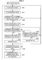
- Figs. 9 is a flowchart and Fig. 10 includes diagrams each showing a transition of a depressing force, for explaining the input control process in this embodiment.
- step S405 When the input control process in Fig. 9 is started, an input position is obtained in step S405, and the depressing force of an operating finger which depresses the touch panel 120 is obtained in step S410.
- the input control unit 220 determines whether or not a differential value of the depressing force of an operator has exceeded the predetermined first threshold value 240c.
- the differential value of the depressing force of the operator is a difference value ( ⁇ Pd: change amount of the depressing force) between a depressing force obtained at an immediately preceding time and the depressing force obtained at a current time
- ⁇ Pd change amount of the depressing force
- step S905 When the depressing force increases and then it is determined in step S905 that the difference value ⁇ Pd of the depressing force has exceeded the first threshold value 240c, the input control unit 220 determines that the operator is in a state of performing input by depression. The operation then proceeds to step S910, and the input control unit 220 records X and Y coordinates (X1, Y1) of the input position in the recording unit 240 as the position of an input candidate.
- a function of the input control unit 220 of fixing the input position as the position of the input candidate at a predetermined timing is executed at the stage prior to the input candidate determination operation of determining the input candidate as input information.
- a time t 1 is a timing at which it has been determined that the depression operation was started and an input key was then locked.
- the magnitude of the first threshold value 240c is set to exceed the magnitude of a depressing force variation (increase) caused by each of a usual sliding operation of the finger and noise.
- the input control unit 220 determines whether the depressing force has exceeded the input start threshold value 240a, in step S915. When it is determined that the depressing force has exceeded the input start threshold value 240a, the operation proceeds to step S420 to cause the key to transition to the input start state (preliminary selection state), and then, locking of the input key is released in step S930. That is, fixing of the coordinates of the input position performed in step S910 is canceled at this timing. With this arrangement, the operator may execute the determination operation of key input.
- a time t 2 in the diagram in the lower portion of the page of Fig. 10 is a timing at which the key locking has been released.
- step S915 When it is determined in step S915 that the depressing force has not exceeded the input start threshold value 240a, the operation proceeds to step S920 to determine whether or not the difference value ⁇ Pd of the depressing force has changed from a positive value to a negative value. When it is determined that the difference value ⁇ Pd of the depressing force has not changed from the positive value to the negative value, the operation is returned to step S915. On the other hand, when it is determined that the depressing force has changed from the positive value to the negative value, the operation proceeds to step S925 to determine the depression operation has been finished without transition of the input key to the input start state (preliminary selection state). Locking of the key is therefore released, and the operation is returned to step S405.
- a time t 3 in the diagram in the middle portion of the page of Fig. 10 is a timing at which locking of the key has been released.
- the mobile apparatus 10 may receive a subsequent input operation without performing input determination when the operator stops the input operation in the middle of the input operation.
- step S425 determines whether or not the depressing force has fallen below the input end threshold value 240b in step S425 and determines that the depressing force has fallen below the input end threshold value 240b
- the same process as that described above is performed. That is, the operation proceeds to step S430, and transition to the input end state is made. Input of the key corresponding to the input position is determined, and the input operation of the key is finished.
- a time t 4 in the diagram in the lower portion of the page of Fig. 10 is a timing at which the input determination has been made, and then the input has been finished.
- Fig. 11 is a flowchart
- Fig. 12 includes diagrams each showing a transition of a depressing force, for explaining an input control process in this embodiment.
- the second embodiment prevents erroneous button depression which may occur due to an unintentional change in coordinates of a position of input by a finger of an operator at a time of a depressing force increase. Further, the second embodiment solves a problem that the coordinates of an input position is fixed though the operator does not intend to fix the coordinates of the input position.
- step S405 When the input control process in Fig. 11 is started, an input position is obtained in step S405 and the depressing force of an operating finger which depresses the touch panel 120 is obtained in step S410.
- the input control unit 220 determines whether or not the difference value ⁇ Pd (increase amount) between a depressing force obtained at an immediately preceding time and the depressing force obtained at a current time, which is a differential value of the depressing force of an operator, has exceeded the predetermined first threshold value 240c.
- the difference value ⁇ Pd has not exceeded the predetermined first threshold value 240c
- the operation is returned to step S405, and the processes in steps S405, S410, and S905 are executed.
- step S905 When it is determined in step S905 that the difference value ⁇ Pd of the depressing force has exceeded the predetermined first threshold value 240c, the input control unit 220 determines that the operator is going to perform input by depression. The operation then proceeds to step S910, and the input control unit 220 records X and Y coordinates (X1, Y1) of the input position in the storage unit 240.
- a time t 1 is a timing at which it has been determined that the depression operation was started and an input key was then locked.
- the input control unit 220 determines whether or not the depressing force has exceeded the input start threshold value 240a, in step S915.
- the operation proceeds to step S420 to cause the key to the input start state (preliminary selection state).
- locking of the input key is released in step S930. That is, fixing of the coordinates of the input position performed in step S910 is canceled at this timing.
- step S915 when it is determined that the depressing force has not exceeded the input start threshold 240a in step S915, the operation proceeds to step S1105. Then, the input control unit 220 determines whether or not a change amount of the input position has exceeded the second threshold value 240d. When it is determined that the change amount of the input position has not exceeded the second threshold value 240d, the operation is returned to step S915. When it is determined that the change amount of the input position has exceeded the second threshold value 240d, the operation proceeds to step S925. The input control unit determines that the coordinate value change of the input position is intended by the operator. Then, locking of the key is released. The operation is then returned to step S405.
- the mobile apparatus 10 may receive a subsequent input operation without making input determination when the operator stops the input operation in the middle of the input operation.
- the description using Fig. 12 was directed to the case of the amount of change in the Y coordinate.
- a similar operation may be used when a change in the X coordinate occurs. That is, also when an amount of change in the X coordinate has exceeded a predetermined threshold value ( ⁇ X), locking of the key is released.
- ⁇ X predetermined threshold value
- Each of threshold values ⁇ X and ⁇ Y as the second threshold value 240d is determined, based on the magnitude of deformation of the finger or the magnitude of a coordinate displacement caused by an input position deviation when the finger has normally depressed a button (key) .
- step S425 determines whether or not the depressing force has fallen below the input end threshold value 240b in step S425 and determines that the depressing force has fallen below the input end threshold value 240b. That is, the operation proceeds to step S430, input of the key corresponding to the input position is determined, and transition to the input end state is made, thereby finishing the input operation of the key.
- Fig. 13 is a flowchart
- Fig. 14 includes diagrams each showing a transition of a depressing force, for explaining an input control process in this embodiment.
- step S405 When the input control process in Fig. 13 is started, an input position is obtained in step S405 and the depressing force of an operating finger which depresses the touch panel 120 is obtained in step S410.
- the input control unit 220 determines whether or not the difference value ⁇ Pd (increase amount) between a depressing force obtained at an immediately preceding time and the depressing force obtained at a current time has exceeded the predetermined first threshold value 240c, in step S905.
- the operation is returned to step S405, and the processes in steps S405, S410, and S905 are executed.
- step S905 When it is determined that the difference value ⁇ Pd has exceeded the predetermined first threshold value 240c in step S905, the input control unit 220 determines that an operator is going to perform input by depression. Then, the operation proceeds to step S910, and the input control unit 220 records X and Y coordinates (X1, Y1) of the input position in the storage unit 240. Referring to Fig. 14 , a time t 1 is a timing at which it has been determined that the depression operation was started and the input key was then locked.
- the input control unit 220 determines whether or not the depressing force has exceeded the input start threshold value 240a, in step S915.
- the operation proceeds to step S420 to cause the input key to transition to the input start state (preliminary selection state).
- locking of the input key is released in step S930. That is, fixing of the coordinates of the input position performed in step S910 is canceled at this timing.
- step S915 When it is determined in step S915 that the depressing force has not exceeded the input start threshold value 240a, the operation proceeds to step S 1305. Then, the input control unit 220 determines whether or not the depressing force has fallen below the input end threshold value 240b. When it is determined that the depressing force has not fallen below the input end threshold value 240b, the operation is returned to step S915. On the other hand, when it is determined that the depressing force has fallen below the input end threshold value 240b, the input control unit 220 determines that the coordinate value change of the input position is intended by the operator. The operation proceeds to step S925, in which locking of the key is canceled. Then, the operation is returned to step S405.
- a deviation (change amount) of the input position gradually decreases after the deviation has increased. Accordingly, a deviation dY at a time t 2 is reduced from a maximum value ⁇ Y of the deviation at a time tm. Thus, locking of the key is released at the time t 2 in this embodiment.
- This arrangement may solve the problem of a large jump in the coordinate of an input position which may occur at a moment when an operator stops an input operation in the middle of the input operation.
- the input control unit 220 determines whether or not the depressing force has fallen below the input end threshold value 240b, in step S425. When it is determined that the depressing force has fallen below the input end threshold value 240b, the operation proceeds to step S430 to determine input of the key corresponding to the input position.
- the input control unit causes the key to transition to the input end state, thereby finishing the input operation of the key.
- the processes in steps 425 and 430 are the same as those described above.
- a timing at which coordinate fixing (locking of the key) is cancelled after an input start timing may be a timing at which the depressing force has fallen below the input end threshold value 240b.
- the timing at which the coordinate fixing is cancelled may be a timing at which the depressing force has fallen below a desired given value.
- the desired given value may be a third threshold value smaller than the input start threshold value.
- fixing of an input candidate position is canceled in response to a timing at which the depressing force has fallen below the third threshold value smaller than the input start threshold value or a timing at which the depressing force has exceeded the input start threshold value after the input candidate position has been fixed.
- This arrangement may prevent erroneous button depression which may occur due to an unintentional change in the coordinates of the position of input by a finger at a time of a depressing force increase when input button depression intended for determination is performed. This arrangement may further solve the problem of a large jump in the coordinates of the input position when key locking is released.
- erroneous input button depression due to an input position deviation at a time of an input operation may be prevented, and an efficient and high-speed input operation may be implemented by a desired depression operation.
- the lock and unlock processes in each of the embodiments may be applied to an operation system in which input determination is made at a timing of a start of input and an operation system in which input determination is made at a timing of an end of input (corresponding to determination by a mouse-up, for example). In both cases, a similar effect may be achieved.
- the operations of the respective units are related to each other and may be replaced with a series of operations and a series of processes in consideration of the relation to each other.
- the embodiment of the information processing apparatus can be thereby converted into the embodiment of an input method of the information processing apparatus and the embodiment of a program for causing a computer to implement functions of the information processing apparatus.
- the present disclosure may be applied to operation of an electronic apparatus such as a remote controller using a touch pad, in which a screen and an operation surface are present at different locations, as well as an electronic apparatus such as a cellular phone including a touch panel. Further, as described above, by using release of locking of input position coordinates when a displacement amount of an operating finger has exceeded the desired threshold value, an input operation for moving input position coordinates with the touch panel or the touch pad kept depressed also becomes possible.
- a touch pad operation is performed by determination of depression
- a PC mouse pad with a mechanical switch installed on a back surface thereof may be pointed out. Even in such an operation system, an intuitive determination operation as with the method described above may be performed.
- a mechanical switch is used, however, an intermediate state of depression of the mechanical switch may not be detected. Accordingly, a position deviation at a time of depression as described in the present disclosure may not be prevented.
- the depression determination method of the present disclosure using a touch panel or a touch pad capable of detecting a depressing force is useful as a technique that is more advantageous to other methods.
- Input information which is applied to an input operation includes numerals and signs as well as characters such as katakanas, hiraganas, kanjis, and English alphabets.
Abstract
Description
- The present disclosure relates to an information processing apparatus, an input control method of the information processing apparatus, and a program.
- In recent years, various electronic apparatuses such as cellular phones, personal digital assistants, personal computers, and car navigation systems which employ a touch panel or a touch pad for input operation have been put into practical use. In these apparatuses, it is a common practice to detect a position of touch using a tap operation with a stylus or an operating finger to perform selection and an input determination operation of a menu button, a software keyboard key, or the like. However, when the selection and the input determination are performed by the tap operation, the size of the button is small with respect to the size of the operating finger or the stylus, so that erroneous depression may often occur.
- In order to cope with this problem, there is proposed a method using a pressure-sensitive sensor mounted on an apparatus. In this method, depression of a virtual key on a software keyboard is detected by the pressure-sensitive sensor. While obtaining tactile feedback using the depressing force of the virtual key, key input is performed (refer to
JP-T-1999-119882 JP-T-1999-119882 JP-T-1999-119882 - According to the operation method disclosed in
JP-T-1999-119882 - On contrast therewith, there is also proposed an input method using a touch panel capable of detecting a proximity state of a button. In this method, a button in a proximity and preliminary selection state is presented to an operator, using a change in display. When the button transitions from the proximity state to a touch state, for example, an input determination operation of the button is performed. With this arrangement, after confirming that the button intended to be input has been selected, input determination of the button may be made. Accordingly, a touch error as described above may be reduced. Further, even if the size of each button is small with respect to the size of an operating finger or a stylus, the selection operation and the input determination operation of the button may be correctly performed.
- However, when the operator performs the input determination operation by depression of or access to the button in the preliminary selection state by his operating finger after confirming the button in the preliminary selection state, the position of the operating finger may unintentionally change. In that case, according to the input control method described above, the operator may unintentionally input a different button which is present in the proximity of the button in the preliminary selection state.
- This problem may be manifest especially when the size of a button is smaller than the size of the operating finger, or when a pitch of buttons is narrow as in the case of a keyboard screen on which buttons are arranged in the form of tiles. To take an example, when the input determination operation is performed by depressing an "e" button of a software keyboard displayed on the screen of a personal
digital assistant 10, as shown inFig. 2 , an operator increases the depressing force of his finger. At that point, the position of the finger may deviate in a direction toward the base of the finger. Consequently, the position of the finger may change to a "d" button when depression of the "e" button is determined. As a result, input of the "d" button may be determined. - Various respective aspects and features of the invention are defined in the appended claims. Combinations of features from the dependent claims may be combined with features of the independent claims as appropriate and not merely as explicitly set out in the claims.
- The present disclosure has been made in view of the above-mentioned problems. It is desirable to provide an information processing apparatus, an input control method of the information processing apparatus, and a program related to input control based on a depression operation, in which erroneous input button depression due to an input position deviation at a time of an input operation may be prevented, and an efficient and high-speed input operation may be performed by a desired depression operation.
- According to an embodiment of the present disclosure, there is provided an information processing apparatus including: an input position acquisition unit which obtains an input position detected with respect to an input operation; a depressing force acquisition unit which obtains a depressing force detected with respect to the input operation; and an input control unit which fixes the input position as a position of an input candidate in response to a timing at which an increase amount of the depressing force has exceeded a first threshold value, at a stage prior to an input candidate determination operation of determining the input candidate as input information.
- According to another embodiment of the present disclosure, there is provided an input control method of an information processing apparatus, including:obtaining an input position detected with respect to an input operation; obtaining a depressing force detected with respect to the input operation; and fixing the input position as a position of an input candidate in response to a timing at which an increase amount of the depressing force has exceeded a first threshold value, at a stage prior to an input candidate determination operation of determining the input candidate as input information.
- According to another embodiment of the present disclosure, there is provided a program for causing a computer to execute functions of: an input position acquisition unit which obtains an input position detected with respect to an input operation; a depressing force acquisition unit which obtains a depressing force detected with respect to the input operation; and an input control unit which fixes the input position as a position of an input candidate in response to a timing at which an increase amount of the depressing force has exceeded a first threshold value, at a stage prior to an input candidate determination operation of determining the input candidate as input information.
- As described above, according to the present disclosure, erroneous input button depression due to an input position deviation at a time of an input operation may be prevented, and an efficient and high-speed input operation may be implemented by a desired depression operation.
- Embodiments of the invention will now be described with reference to the accompanying drawings, throughout which like parts are referred to by like references, and in which:
-
Fig. 1 includes diagrams showing a schematic configuration of a mobile apparatus according to first to third embodiments of the present disclosure; -
Fig. 2 includes diagrams showing an example of an input operation of the mobile apparatus according to the first to third embodiments; -
Fig. 3 is a functional configuration diagram of the mobile apparatus according to the first to third embodiments; -
Fig. 4 is a flowchart showing an input control process example 1; -
Fig. 5 is a graph for explaining a transition of a state of a selected input candidate in the input control process inFig. 4 ; -
Fig. 6 is a graph for explaining a transition of a state of the selected input candidate in the input control process inFig. 4 ; -
Fig. 7 is a flowchart showing an input control process example 2; -
Fig. 8 is a graph for explaining a transition of a state of a selected input candidate in the input control process inFig. 7 ; -
Fig. 9 is a flowchart showing an input control process according to the first embodiment; -
Fig. 10 includes graphs for explaining a transition of a locked state of an input candidate locked state in the input control process inFig. 9 ; -
Fig. 11 is a flowchart showing an input control process in a second embodiment; -
Fig. 12 includes graphs for explaining a transition of a locked state of an input candidate locked state in the input control process inFig. 11 ; -
Fig. 13 is a flowchart showing an input control process according to a third embodiment; and -
Fig. 14 includes graphs for explaining a transition of a locked state of an input candidate in the input control process inFig. 13 . - Hereinafter, preferred embodiments of the present disclosure will be described in detail with reference to the appended drawings. Note that, in this specification and the appended drawings, structural elements that have substantially the same function and structure are denoted with the same reference numerals, and repeated explanation of these structural elements is omitted.
- The embodiments of the present disclosure will be described in the following order.
-
- [1-1. Hardware Configuration of Mobile Apparatus]
- [1-2. Functional Configuration of Mobile Apparatus]
- [1-3. Input Control Process Example 1]
- [1-4. Input Control Process Example 2]
- [1-5. Operation of Mobile Apparatus]
(Input Control Process) -
- [2-1. Operation of Mobile Apparatus]
(Input Control Process) -
- [3-1. Operation of Mobile Apparatus]
(Input Control Process) - First, a hardware configuration of a mobile apparatus according to a first embodiment of the present disclosure will be described with reference to
Figs. 1 and2 . A diagram illustrated in the lower portion of the page ofFig. 1 is a plan view of amobile apparatus 10 including adisplay screen 10a. As thedisplay screen 10a, a liquid crystal display (LCD: Liquid Crystal Display), an organic electroluminescene display (organic EL, OELD: Organic Electroluminescence Display) or the like, for example, may be employed. - The
mobile apparatus 10 is an example of an information processing apparatus capable of receiving information by touching or depressing thedisplay screen 10a. The information processing apparatus may be a PC (Personal Computer), a cellular phone, a smart phone, a portable music player, a personal digital assistant (PDA: Personal Digital Assistant), a game apparatus, or a digital household appliance. - A diagram illustrated in the upper portion of the page of
Fig. 1 is a sectional view of themobile apparatus 10 shown in the diagram in the lower portion of the page ofFig. 1 , taken along aline 1 ― 1. As shown in the diagram in the upper portion of the page ofFig. 1 , themobile apparatus 10 includes abase member 100, a pressure-sensitive sensor 110, atouch panel 120, an electrically conductive vapor-depositedfilm 130, atop plate 140, and an electricallyconductive housing 150. - The
base member 100 constitutes the bottom portion of themobile apparatus 10, and is formed of a resin substrate or the like, for example. The pressure-sensitive sensor 110 is in the shape of a sheet, and is shaped like a substantially rectangular frame. Referring to a diagram on the left side of the page ofFig. 1 in which the pressure-sensitive sensor 110 has been enlarged, the pressure-sensitive sensor 110 has a structure in which a pressure-sensitive electricallyconductive rubber 110a is sandwiched between twosheet panels 110b that form electrode surfaces. - The
touch panel 120 is disposed directly on the pressure-sensitive sensor 110. Thetouch panel 120 is a touch panel of a capacitance type, and detects a touch position of an operating finger. A display panel not shown is disposed between thetouch panel 120 and thebase member 100. - As shown in
Fig. 2 , there is a key input region Er for displaying a software keyboard on thedisplay screen 10a of the display panel. In this embodiment, the software keyboard with a QWERTY key arrangement capable of receiving "kana" characters and English alphabet characters is displayed in the key input region Er. An operator causes an operating finger to touch or depress a predetermined portion of thetouch panel 120 based on the software keyboard displayed on thedisplay panel 120. Thetouch panel 120 detects X and Y coordinates of the input position of the touch panel the operating finger has touched. The X and Y coordinates detected by thetouch panel 120 are transmitted to acontroller 160. - The electrically conductive vapor-deposited
film 130 is a thin metal film formed in the shape of a frame by vapor deposition, and covers an upper surface of the pressuresensitive sensor 110 via thetouch panel 120. The electrically conductive vapor-depositedfilm 130 does not exist on a region other than a peripheral edge portion of thetouch panel 120. Thus, the electrically conductive vapor-depositedfilm 130 does not affect position detection by thetouch panel 120. - The
top plate 140 is formed above thetouch panel 120 with the electrically conductive vapor-deposited film sandwiched between thetop plate 140 and thetouch panel 120. Thetop plate 140 protects thetouch panel 120 and prevents thetouch panel 120 from being scratched. Thetop plate 140 is formed of a glass substrate or a resin substrate, for example. The finger depresses thetouch panel 120 via thetop plate 140. - The electrically
conductive housing 150 is a frame body surrounding the outer periphery of thetouch panel 120, and is fitted in thebase member 100. The electricallyconductive housing 150 is formed of an electrically conductive material mainly made of aluminum, an electrically conductive rubber, electrically conductive carbon, or the like, for example, and is connected to the ground. With this arrangement, the electricallyconductive housing 150 includes a function of blocking electrical connection between the operating finger which comes close to themobile apparatus 10 from a side surface of themobile apparatus 10 and the pressure-sensitive sensor 110. A projectingportion 150a projecting toward an inside of the electricallyconductive housing 150 is formed at the center of an inner wall of the electricallyconductive housing 150. The pressure-sensitive sensor 110, thetouch panel 120, the electrically conductive vapor-depositedfilm 130, and thetop plate 140 are laminated in this stated order, and are disposed inside the electricallyconductive housing 150, being supported by the projectingportion 150a of the electricallyconductive housing 150. The projectingportion 150a of the electricallyconductive housing 150 includes a function of blocking electrical connection between the pressure-sensitive sensor 110 and the operating finger which has come close from a bottom direction of themobile apparatus 10. - When the pressure-sensitive electrically
conductive rubber 110a deforms with respect to depression of the display surface by the operating finger, the pressure-sensitive sensor 110 detects electrical conduction of the portion of deformation of the pressure-sensitive electrically conductive rubber, thereby detecting a depressing force. The value of detection by the pressure-sensitive sensor 110 is transmitted to thecontroller 160 and is converted to an electrical signal indicating the depressing force (depression pressure). An insulator not shown is formed on the surface of eachsheet panel 110b. Thecontroller 160 is a microprocessor included in themobile apparatus 10. - A functional configuration of the
mobile apparatus 10 will be described now with reference toFig. 3 . Themobile apparatus 10 includes a depressingforce acquisition unit 200, an inputposition acquisition unit 210, aninput control unit 220, adisplay control unit 230, and astorage unit 240. - The depressing
force acquisition unit 200 obtains a depressing force detected with respect to an input operation. When performing an input operation, a user causes an operating finger to touch a predetermined position on the touch panel, and depresses the predetermined position. When a pressure is applied to the top plate 140 (touch panel 120) by depression by the finger, the pressure-sensitive electricallyconductive rubber 110a deforms (contracts) according to the pressure. When the pressure-sensitive electricallyconductive rubber 110a contracts, a capacitance between the electrodes changes. The capacitance of the pressure-sensitive sensor 110 is transmitted to thecontroller 160 connected to the pressure-sensitive sensor 110, and is converted to an electrical signal indicating the depressing force (depression pressure). The electrical signal obtained by the conversion is transmitted to the depressingforce acquisition unit 200 from thecontroller 160. In this manner, the depressingforce acquisition unit 200 acquires the depressing force detected with respect to the input operation. - The input
position acquisition unit 210 acquires the position of input detected with respect to the input operation. When performing the input operation, the user causes the operating finger to touch the predetermined position on the touch panel. Thetouch panel 120 detects X and Y coordinates touched by the operating finger, as the position of input. The X and Y coordinates detected by thetouch panel 120 are transmitted to the inputposition acquisition unit 210 via thecontroller 160. In this manner, the inputposition acquisition unit 210 obtains the position of input detected with respect to the input operation. - The
input control unit 220 fixes the position of input as the position of an input candidate, in response to a timing at which an increase amount of the depressing force has exceeded a first threshold value, at a stage prior to an input candidate determination operation of determining the input candidate as input information. The operation prior to the input candidate determination operation and the input candidate determination operation will be described later. - The
display control unit 230 controls information to be displayed on thedisplay screen 10a. To take an example, thedisplay control unit 230 may perform control such that, when the operating finger has touched thetouch panel 120, a pop-up display of a character "e" at the position of touch is performed, as shown in a diagram on the left side of the page ofFig. 2 . Further, thedisplay control unit 230 may perform control such that, when the operating finger is depressed for determination, the pop-up display of the character "e" at the position of depression is highlighted, as shown in a diagram illustrated on the right side of the page ofFig. 2 , for example. In addition, thedisplay control unit 230 may change screen display according to the operation by the operating finger. - The
storage unit 240 stores an inputstart threshold value 240a, an inputend threshold value 240b, afirst threshold value 240c, asecond threshold value 240d, and the like, as parameters necessary for the input candidate determination operation and the operation prior to the input candidate determination operation. - Actually, the
mobile apparatus 10 described above includes a CPU, a RAM, a non-volatile memory, and the like not shown, and each of the functions of themobile apparatus 10 is executed by the CPU. Likewise, thecontroller 160 also includes a CPU, a RAM, a non-volatile memory, and the like not shown. Information on the depressing force and the coordinates of the input position transmitted from thecontroller 160 is stored in the RAM and the non-volatile memory. The CPU analyzes the operation of the operating finger, based on the depressing force and the X and Y coordinates (of the input position) stored in the RAM and the like. The CPU controls an input operation to themobile apparatus 10 based on the analyzed operation of the operating finger. - The input candidate determination operation not including lock and unlock operations of an input candidate will be described now, with reference to
Figs. 4 to 8 before description of the lock and unlock operations, which are a feature of an input control method in this embodiment.Figs. 4 to 6 are a flowchart and diagrams each showing a transition of a depressing force, for explaining an input control process example 1.Figs. 7 and8 are a flowchart and a diagram showing a transition of a depressing force, for explaining an input control process example 2. Lock and unlock processes in this embodiment constitute the operation prior to the input candidate determination operation. A preliminary selection process and an input determination process constitute the input candidate determination operation. - When the input control process in
Fig. 4 is started, the inputposition acquisition unit 210 obtains X and Y coordinates of a position of thetouch panel 120 touched by an operating finger, as an input position, in step S405. Next, the depressingforce acquisition unit 200 obtains the depressing force of the operating finger which depresses thetouch panel 120, in step S410. - Next, the
input control unit 220 determines whether or not the depressing force has exceeded the inputstart threshold value 240a, in step S415. When it is determined that the depressing force has not exceeded the inputstart threshold value 240a, the operation is returned to step S405, and the processes in steps S405 to S415 are executed again. - When it is determined in step S415 that the depressing force has exceeded the input
start threshold value 240a, the operation proceeds to step S420 to cause transition of a key at the input position to an input start state (preliminary selection state or determination standby state). A time t1 inFig. 5 indicates a timing of preliminary selection of the key, or a timing at which the transition to the determination standby state has been made. In response to this timing, thedisplay control unit 230 may show the preliminary selection state to a user as shown inFig. 2 in which the pop-up display of the character "e" is highlighted. - Next, the operation proceeds to step S425, in which the
input control unit 220 determines whether or not the depressing force has fallen below theinput end threshold 240b. The inputend threshold value 240b is set to be smaller than the inputstart threshold value 240a. - While it is determined that the depressing force is not below the input
end threshold value 240b, theinput control unit 220 repeats the process in step S425. When it is determined that the depressing force has fallen below the inputend threshold value 240b, the operation proceeds to step S430. Theinput control unit 220 causes the key to transition to an input end state (standby finish state) in step S430. That is, theinput control unit 220 determines input of the key corresponding to the input position, and causes the input operation of the key to be finished. A time t2 inFig. 5 indicates a timing at which input of the key corresponding to the position of touch by the operating finger has been determined and the transition to the standby finish state has been made. At this timing, the pop-up display of the key "e" inFig. 2 , for example, is finished, and themobile apparatus 10 receives subsequent input of a character. - Assume, for example, that the depressing force has exceeded the input
start threshold value 240a at a time t1 inFig. 6 , and then the depressing force has exceeded the inputstart threshold value 240a again before falling below the inputend threshold value 240b, as shown in a waveform portion a of an electrical signal indicating the depressing force inFig. 6 . Then, input is not determined, because themobile apparatus 10 is not in a state of receiving determination of subsequent input yet. When the depressing force has fallen below the inputend threshold value 240b at a time t2, the input is determined, and themobile apparatus 10 transitions to the state of receiving a subsequent input operation. When the depressing force exceeds the inputstart threshold value 240a again at a time t3 in the subsequent input operation, a key corresponding to an input position at that time is preliminarily selected. When the depressing force has fallen below the inputend threshold value 240b again, input of the key corresponding to the input position at that time is determined, and themobile apparatus 10 becomes the state of receiving subsequent input of a character. - By performing enlarged display and display of selection of a key (highlighted display of the key) on the screen as shown in
Fig. 2 during the operation, visual feedback for notifying each of the timings to the user may be performed. In addition to this method of the visual feedback, another method may be used for notifying each of the timings to the user. That is, a vibration device such as a vibration motor is included in themobile apparatus 10, and the surface of the touch panel is vibrated by the vibration device at each timing to notify the timing to the user. These methods are effective for achieving an intuitive operation. - As described above, the input control process example 1 may prevent successive input determinations of unintended characters. This phenomenon occurs when a depressing force hovers around the input
start threshold value 240a, for example. Due to a subtle variation of the depressing force and noise of the electrical signal in this condition, the depressing force frequently exceeds the input start threshold value, so that the successive input determinations of unintended characters occur. - Further, according to the input control process example 1, the preliminary selection state of a key is shown to the user by highlighted display of a pop-up character or the like. With this arrangement, the user may adjust a degree of depression and may perform input determination after confirming that an intended button has been selected. A touch error may be thereby reduced. Further, even when the size of the button is small with respect to the operating finger or the size of a stylus, selection and input determination operations of the button may be correctly performed.
- In the input control process example 1 in
Fig. 4 , the determination operation of input by depression is controlled using the absolute value of the depressing force. In place of this method, there may be a method of controlling the input determination operation according to a depressing force variation, as in the following input control process example 2 inFig. 7 . A description will be given below about an example where the input determination operation is controlled according to a depressing force variation, with reference toFig. 7 . - When the input control process in
Fig. 7 is started, the inputposition acquisition unit 210 obtains X and Y coordinates of a position of thetouch panel 120 touched by an operating finger, as an input position, in step S405. Next, the depressingforce acquisition unit 200 obtains the depressing force of the operating finger which depresses thetouch panel 120, in step S410. - Next, the
input control unit 220 determines whether or not the depressing force has changed by a given amount (ΔP1) or more after the depressing force has started to decrease. When it is determined that the depressing force has not decreased by the given amount (ΔP1) or more, the operation is returned to step S405. Then, the processes in steps S405, S410, and S705 are executed again. - When it is determined in step S705 that the depressing force has decreased by the given amount (ΔP1) or more, the operation proceeds to step S420. Transition to the input start state (preliminary selection state or determination standby state) is then made. A time t2 in
Fig. 8 indicates a timing of preliminary selection of a key, a timing at which the transition to the determination standby state has been made, or a timing at which a determination standby flag F has risen to 1 (F = 1). Thedisplay control unit 230 may highlight the pop-up display of the character "e" shown inFig. 2 , in response to this timing. - Next, the operation proceeds to step S710, in which the
input control unit 220 determines whether or not the depressing force has changed by a given amount (ΔP2) or more after the depression has started to increase. While it is determined that the depressing force has not increased by the given amount (ΔP2) or more, theinput control unit 220 repeats the process in step S710. When it is determined that the depressing force has increased by the given amount (ΔP2) or more, the operation proceeds to step S430. Theinput control unit 220 determines input of the key corresponding to the input position in step S430, and causes the input operation of the key to be finished (to the input end state). Then, the determination standby flag is lowered to 0 (F = 0). A time t3 inFig. 8 indicates a timing at which input of the key corresponding to the position of touch by the operating finger has been determined and transition to the input end state has been made. Even if the depressing force increases, the determination operation of an input key is not generated until the depressing force decreases again by the given amount (ΔP1) or more. This arrangement may prevent input of an unintended key with respect to a minute variation of the depressing force caused by noise shown in a waveform portion b of an electrical signal indicating the depressing force inFig. 8 . - When the base level of the variation of the depressing force has risen as shown in a waveform portion c in
Fig. 8 in the input control process example 2 described above, however, the depressing force does not fall below the input end threshold value, thus not allowing successive inputs to be performed. On contrast therewith, in input control process example 1 described above, input determination is controlled by the absolute value of a depressing force. Thus, input determination may be reliably performed by a small variation of the depressing force. Then, themobile apparatus 10 may be promptly brought into the state of receiving subsequent character input. - In the process of executing the input determination operation based on the depressing force after the operator has confirmed the input button (input key) in the preliminary selection state, the position of the operating finger may unintentionally change. In that case, the operator may unintentionally input a different button which is present in the proximity of the button in the preliminary selection state even if either of the input control methods described above is used.
- To cope with this problem, the
mobile apparatus 10 in this embodiment performs the lock operation at the stage prior to the input candidate determination operation, thereby preventing erroneous depression of an input button due to an input position deviation when input button depression is determined. Such an input control method will be described with reference toFigs. 9 and10 .Figs. 9 is a flowchart andFig. 10 includes diagrams each showing a transition of a depressing force, for explaining the input control process in this embodiment. - When the input control process in
Fig. 9 is started, an input position is obtained in step S405, and the depressing force of an operating finger which depresses thetouch panel 120 is obtained in step S410. Next, theinput control unit 220 determines whether or not a differential value of the depressing force of an operator has exceeded the predeterminedfirst threshold value 240c. The differential value of the depressing force of the operator is a difference value (ΔPd: change amount of the depressing force) between a depressing force obtained at an immediately preceding time and the depressing force obtained at a current time When it is determined that the difference value has not exceeded the predeterminedfirst threshold value 240c, the operation is returned to step S405, and the processes in steps S405, S410, and S905 are executed. - When the depressing force increases and then it is determined in step S905 that the difference value ΔPd of the depressing force has exceeded the
first threshold value 240c, theinput control unit 220 determines that the operator is in a state of performing input by depression. The operation then proceeds to step S910, and theinput control unit 220 records X and Y coordinates (X1, Y1) of the input position in therecording unit 240 as the position of an input candidate. By this process, a function of theinput control unit 220 of fixing the input position as the position of the input candidate at a predetermined timing is executed at the stage prior to the input candidate determination operation of determining the input candidate as input information. Referring toFig. 10 , a time t1 is a timing at which it has been determined that the depression operation was started and an input key was then locked. - With this arrangement, the input key is locked. For this reason, even if the operator has further depressed the button (key) and the Y coordinate of the input position has thereby slightly changed just by dY as in a signal waveform portion a in the diagram in the upper portion of the page of
Fig. 10 , this coordinate change is not reflected on subsequent operations for the input. This arrangement solves the problem of depression of an unintended button due to an input position deviation at a time of input button depression and resulting input of the key corresponding to the unintended button. The magnitude of thefirst threshold value 240c is set to exceed the magnitude of a depressing force variation (increase) caused by each of a usual sliding operation of the finger and noise. - Next, the input candidate determination operation is entered. The
input control unit 220 determines whether the depressing force has exceeded the inputstart threshold value 240a, in step S915. When it is determined that the depressing force has exceeded the inputstart threshold value 240a, the operation proceeds to step S420 to cause the key to transition to the input start state (preliminary selection state), and then, locking of the input key is released in step S930. That is, fixing of the coordinates of the input position performed in step S910 is canceled at this timing. With this arrangement, the operator may execute the determination operation of key input. A time t2 in the diagram in the lower portion of the page ofFig. 10 is a timing at which the key locking has been released. - When it is determined in step S915 that the depressing force has not exceeded the input
start threshold value 240a, the operation proceeds to step S920 to determine whether or not the difference value ΔPd of the depressing force has changed from a positive value to a negative value. When it is determined that the difference value ΔPd of the depressing force has not changed from the positive value to the negative value, the operation is returned to step S915. On the other hand, when it is determined that the depressing force has changed from the positive value to the negative value, the operation proceeds to step S925 to determine the depression operation has been finished without transition of the input key to the input start state (preliminary selection state). Locking of the key is therefore released, and the operation is returned to step S405. A time t3 in the diagram in the middle portion of the page ofFig. 10 is a timing at which locking of the key has been released. With this arrangement, themobile apparatus 10 may receive a subsequent input operation without performing input determination when the operator stops the input operation in the middle of the input operation. - When the
input control unit 220 determines whether or not the depressing force has fallen below the inputend threshold value 240b in step S425 and determines that the depressing force has fallen below the inputend threshold value 240b, the same process as that described above is performed. That is, the operation proceeds to step S430, and transition to the input end state is made. Input of the key corresponding to the input position is determined, and the input operation of the key is finished. A time t4 in the diagram in the lower portion of the page ofFig. 10 is a timing at which the input determination has been made, and then the input has been finished. - As described above, in an input operation of an apparatus using a touch panel or a touch pad in which input determination is made according to a depressing force variation, when button depression intended for input determination is performed, erroneous button depression may often occur due to an unintentional change in coordinates of a position of input by a finger at a time of a depressing force increase. On contrast therewith, in the input control method of the
mobile apparatus 10 in this embodiment, coordinates of a key being depressed is locked for a predetermined period of time, using information on the depressing force of the key. With this arrangement, erroneous button depression caused by an unintentional input position deviation of a finger after locking of the key may be prevented, so that an efficient and high-speed input operation using a desired depression operation may be implemented. Further, according to this embodiment, after an input candidate position has been fixed, fixing of the input candidate position is canceled in response to a timing at which the depressing force has started to decrease after having increased, or in response to a timing at which the depressing force has exceeded the input start threshold value. With this arrangement, when an operator stops an input operation in the middle of the input operation, key locking is intentionally released by changing the depressing force from a positive value to a negative value. Themobile apparatus 10 may thereby receive a subsequent input operation without making input determination. - Next, an input control method which is executed in the
mobile apparatus 10 in a second embodiment will be described with reference toFigs. 11 and12 .Fig. 11 is a flowchart, andFig. 12 includes diagrams each showing a transition of a depressing force, for explaining an input control process in this embodiment. The second embodiment prevents erroneous button depression which may occur due to an unintentional change in coordinates of a position of input by a finger of an operator at a time of a depressing force increase. Further, the second embodiment solves a problem that the coordinates of an input position is fixed though the operator does not intend to fix the coordinates of the input position. - When the input control process in
Fig. 11 is started, an input position is obtained in step S405 and the depressing force of an operating finger which depresses thetouch panel 120 is obtained in step S410. Next, theinput control unit 220 determines whether or not the difference value ΔPd (increase amount) between a depressing force obtained at an immediately preceding time and the depressing force obtained at a current time, which is a differential value of the depressing force of an operator, has exceeded the predeterminedfirst threshold value 240c. When it is determined that the difference value ΔPd has not exceeded the predeterminedfirst threshold value 240c, the operation is returned to step S405, and the processes in steps S405, S410, and S905 are executed. - When it is determined in step S905 that the difference value ΔPd of the depressing force has exceeded the predetermined
first threshold value 240c, theinput control unit 220 determines that the operator is going to perform input by depression. The operation then proceeds to step S910, and theinput control unit 220 records X and Y coordinates (X1, Y1) of the input position in thestorage unit 240. Referring toFig. 12 , a time t1 is a timing at which it has been determined that the depression operation was started and an input key was then locked. - The input key is thereby locked. For this reason, even if the operator has further depressed the button (key) and the coordinate of the input position has thereby slightly changed, this coordinate change is not reflected on subsequent operations for the input. This arrangement solves the problem of depression of an unintended button caused by an input position deviation at a time of input button depression and resulting unintentional input of the key corresponding to the button.
- Next, the input candidate determination operation is entered. The
input control unit 220 determines whether or not the depressing force has exceeded the inputstart threshold value 240a, in step S915. When it is determined that the depressing force has exceeded the inputstart threshold value 240a, the operation proceeds to step S420 to cause the key to the input start state (preliminary selection state). Then, locking of the input key is released in step S930. That is, fixing of the coordinates of the input position performed in step S910 is canceled at this timing. - On the other hand, when it is determined that the depressing force has not exceeded the
input start threshold 240a in step S915, the operation proceeds to step S1105. Then, theinput control unit 220 determines whether or not a change amount of the input position has exceeded thesecond threshold value 240d. When it is determined that the change amount of the input position has not exceeded thesecond threshold value 240d, the operation is returned to step S915. When it is determined that the change amount of the input position has exceeded thesecond threshold value 240d, the operation proceeds to step S925. The input control unit determines that the coordinate value change of the input position is intended by the operator. Then, locking of the key is released. The operation is then returned to step S405. Assume that an amount of change ΔY in the Y coordinate of the input position in a waveform portion a inFig. 12 has gradually increased and has then exceeded thesecond threshold value 240d at a time t2. In this case, locking of the key is released at the time t2 in this embodiment. With this arrangement, themobile apparatus 10 may receive a subsequent input operation without making input determination when the operator stops the input operation in the middle of the input operation. The description usingFig. 12 was directed to the case of the amount of change in the Y coordinate. A similar operation may be used when a change in the X coordinate occurs. That is, also when an amount of change in the X coordinate has exceeded a predetermined threshold value (ΔX), locking of the key is released. Each of threshold values ΔX and ΔY as thesecond threshold value 240d is determined, based on the magnitude of deformation of the finger or the magnitude of a coordinate displacement caused by an input position deviation when the finger has normally depressed a button (key) . - When the
input control unit 220 determines whether or not the depressing force has fallen below the inputend threshold value 240b in step S425 and determines that the depressing force has fallen below the inputend threshold value 240b, the same process as that described above is performed. That is, the operation proceeds to step S430, input of the key corresponding to the input position is determined, and transition to the input end state is made, thereby finishing the input operation of the key. - As described above, according to this embodiment, after an input candidate position has been fixed, fixing of the input candidate position is canceled in response to a timing at which an input position change amount has exceeded the second threshold value or a timing at which the depressing force has exceeded the input start threshold. This arrangement may prevent erroneous button depression which may occur due to an unintentional change in the coordinates of the position of input by a finger at a time of a depressing force increase when input button depression intended for determination is performed. Further, with this arrangement, key locking is released by intentionally changing a touch position. This release of key locking may solve the problem that the coordinates of an input position is fixed though an operator does not intend to fix the coordinates of the input position.
- Next, an input control method which is executed in the
mobile apparatus 10 in a third embodiment will be described with reference toFigs. 13 and14 .Fig. 13 is a flowchart, andFig. 14 includes diagrams each showing a transition of a depressing force, for explaining an input control process in this embodiment. - In the first embodiment, locking of the key is released at the time t3 as shown in
Fig. 10 , too. Accordingly, fixing of the key is generally cancelled when a coordinate deviation of an input position (a difference dx or dy between the coordinate at the start of the fixing and the coordinate at the end of the fixing) is close to the maximum. For that reason, a large jump may occur in the coordinates of the input position immediately after the cancellation of the fixing. In the case of a keyboard, for example, pop-up of a different key is likely to be displayed immediately after the cancellation of the fixing has been made. The third embodiment solves the problem of a coordinate jump which may occur when such fixing of a key is canceled. - When the input control process in
Fig. 13 is started, an input position is obtained in step S405 and the depressing force of an operating finger which depresses thetouch panel 120 is obtained in step S410. Next, theinput control unit 220 determines whether or not the difference value ΔPd (increase amount) between a depressing force obtained at an immediately preceding time and the depressing force obtained at a current time has exceeded the predeterminedfirst threshold value 240c, in step S905. When it is determined that the difference value ΔPd has not exceeded the predeterminedfirst threshold value 240c, the operation is returned to step S405, and the processes in steps S405, S410, and S905 are executed. - When it is determined that the difference value ΔPd has exceeded the predetermined
first threshold value 240c in step S905, theinput control unit 220 determines that an operator is going to perform input by depression. Then, the operation proceeds to step S910, and theinput control unit 220 records X and Y coordinates (X1, Y1) of the input position in thestorage unit 240. Referring toFig. 14 , a time t1 is a timing at which it has been determined that the depression operation was started and the input key was then locked. - The input key is thereby locked. For this reason, even if the operator has further depressed the button (key) and the coordinate of the input position has slightly changed, this coordinate change is not reflected on subsequent operations for the input. With this arrangement in this condition, the problem of depression of an unintended button due to an input position deviation at a time of input button depression and resulting input of the key corresponding to the unintended button is solved.
- Next, the input candidate determination operation is entered. The
input control unit 220 determines whether or not the depressing force has exceeded the inputstart threshold value 240a, in step S915. When it is determined that the depressing force has exceeded the inputstart threshold value 240a, the operation proceeds to step S420 to cause the input key to transition to the input start state (preliminary selection state). Then, locking of the input key is released in step S930. That is, fixing of the coordinates of the input position performed in step S910 is canceled at this timing. - When it is determined in step S915 that the depressing force has not exceeded the input
start threshold value 240a, the operation proceeds to step S 1305. Then, theinput control unit 220 determines whether or not the depressing force has fallen below the inputend threshold value 240b. When it is determined that the depressing force has not fallen below the inputend threshold value 240b, the operation is returned to step S915. On the other hand, when it is determined that the depressing force has fallen below the inputend threshold value 240b, theinput control unit 220 determines that the coordinate value change of the input position is intended by the operator. The operation proceeds to step S925, in which locking of the key is canceled. Then, the operation is returned to step S405. - It can be seen from a signal waveform portion a in
Fig. 14 that a deviation (change amount) of the input position gradually decreases after the deviation has increased. Accordingly, a deviation dY at a time t2 is reduced from a maximum value ΔY of the deviation at a time tm. Thus, locking of the key is released at the time t2 in this embodiment. This arrangement may solve the problem of a large jump in the coordinate of an input position which may occur at a moment when an operator stops an input operation in the middle of the input operation. - The
input control unit 220 determines whether or not the depressing force has fallen below the inputend threshold value 240b, in step S425. When it is determined that the depressing force has fallen below the inputend threshold value 240b, the operation proceeds to step S430 to determine input of the key corresponding to the input position. The input control unit causes the key to transition to the input end state, thereby finishing the input operation of the key. The processes insteps 425 and 430 are the same as those described above. - A timing at which coordinate fixing (locking of the key) is cancelled after an input start timing may be a timing at which the depressing force has fallen below the input
end threshold value 240b. Alternatively, the timing at which the coordinate fixing is cancelled may be a timing at which the depressing force has fallen below a desired given value. The desired given value may be a third threshold value smaller than the input start threshold value. - As described above, according to this embodiment, fixing of an input candidate position is canceled in response to a timing at which the depressing force has fallen below the third threshold value smaller than the input start threshold value or a timing at which the depressing force has exceeded the input start threshold value after the input candidate position has been fixed. This arrangement may prevent erroneous button depression which may occur due to an unintentional change in the coordinates of the position of input by a finger at a time of a depressing force increase when input button depression intended for determination is performed. This arrangement may further solve the problem of a large jump in the coordinates of the input position when key locking is released.
- As described above, according to the input control method using the mobile apparatus in each embodiment, erroneous input button depression due to an input position deviation at a time of an input operation may be prevented, and an efficient and high-speed input operation may be implemented by a desired depression operation.
- In each of the embodiments described above, as a basic process of the input candidate determination operation, erroneous input button depression is prevented by adding the lock and unlock processes in each of the embodiments to the input method of input control process example 1 shown in
Fig. 4 . This basic process, however, is not limited to this process. The lock and unlock processes in each of the embodiments may be added to the input method of input control process example 2 shown inFig. 7 . - The lock and unlock processes in each of the embodiments may be applied to an operation system in which input determination is made at a timing of a start of input and an operation system in which input determination is made at a timing of an end of input (corresponding to determination by a mouse-up, for example). In both cases, a similar effect may be achieved.
- In the first to third embodiments described above, the operations of the respective units are related to each other and may be replaced with a series of operations and a series of processes in consideration of the relation to each other. The embodiment of the information processing apparatus can be thereby converted into the embodiment of an input method of the information processing apparatus and the embodiment of a program for causing a computer to implement functions of the information processing apparatus.
- Although preferred embodiments of the present disclosure are described in detail above with reference to the appended drawings, the present disclosure is not limited thereto. It should be understood by those skilled in the art that various modifications, combinations, sub-combinations and alterations may occur depending on design requirements and other factors insofar as they are within the scope of the appended claims or the equivalents thereof.
- The present disclosure may be applied to operation of an electronic apparatus such as a remote controller using a touch pad, in which a screen and an operation surface are present at different locations, as well as an electronic apparatus such as a cellular phone including a touch panel. Further, as described above, by using release of locking of input position coordinates when a displacement amount of an operating finger has exceeded the desired threshold value, an input operation for moving input position coordinates with the touch panel or the touch pad kept depressed also becomes possible.
- As an example where a touch pad operation is performed by determination of depression, a PC mouse pad with a mechanical switch installed on a back surface thereof may be pointed out. Even in such an operation system, an intuitive determination operation as with the method described above may be performed. When a mechanical switch is used, however, an intermediate state of depression of the mechanical switch may not be detected. Accordingly, a position deviation at a time of depression as described in the present disclosure may not be prevented. The depression determination method of the present disclosure using a touch panel or a touch pad capable of detecting a depressing force is useful as a technique that is more advantageous to other methods.
- Input information which is applied to an input operation according to the present disclosure includes numerals and signs as well as characters such as katakanas, hiraganas, kanjis, and English alphabets.
- In so far as the embodiments of the invention described above are implemented, at least in part, using software-controlled data processing apparatus, it will be appreciated that a computer program providing such software control and a transmission, storage or other medium by which such a computer program is provided are envisaged as aspects of the present invention.
- The present disclosure contains subject matter related to that disclosed in Japanese Priority Patent Application
JP 2010-196815
Claims (6)
- An information processing apparatus comprising:an input position acquisition unit which obtains an input position detected with respect to an input operation;a depressing force acquisition unit which obtains a depressing force detected with respect to the input operation; andan input control unit which fixes the input position as a position of an input candidate in response to a timing at which an increase amount of the depressing force has exceeded a first threshold value, at a stage prior to an input candidate determination operation of determining the input candidate as input information.
- The information processing apparatus according to claim 1, wherein
after the position of the input candidate has been fixed, the input control unit cancels fixing of the input candidate position in response to a timing at which the depressing force has started to decrease after having increased, or a timing at which the depressing force has exceeded an input start threshold value. - The information processing apparatus according to claim 1, wherein
after the position of the input candidate has been fixed, the input control unit cancels fixing of the input candidate position in response to a timing at which a change amount of the input position has exceeded a second threshold value, or a timing at which the depressing force has exceeded an input start threshold value. - The information processing apparatus according to claim 1, wherein
after the position of the input candidate has been fixed, the input control unit cancels fixing of the input candidate position in response to a timing at which the depressing force has fallen below a third threshold value smaller than an input start threshold value, or a timing at which the depressing force has exceeded the input start threshold value. - An input control method of an information processing apparatus, comprising:obtaining an input position detected with respect to an input operation;obtaining a depressing force detected with respect to the input operation; andfixing the input position as a position of an input candidate in response to a timing at which an increase amount of the depressing force has exceeded a first threshold value, at a stage prior to an input candidate determination operation of determining the input candidate as input information.
- A program for causing a computer to execute functions of:an input position acquisition unit which obtains an input position detected with respect to an input operation;a depressing force acquisition unit which obtains a depressing force detected with respect to the input operation; andan input control unit which fixes the input position as a position of an input candidate in response to a timing at which an increase amount of the depressing force has exceeded a first threshold value, at a stage prior to an input candidate determination operation of determining the input candidate as input information.
Applications Claiming Priority (1)
| Application Number | Priority Date | Filing Date | Title |
|---|---|---|---|
| JP2010196815A JP5732783B2 (en) | 2010-09-02 | 2010-09-02 | Information processing apparatus, input control method for information processing apparatus, and program |
Publications (3)
| Publication Number | Publication Date |
|---|---|
| EP2426580A2 true EP2426580A2 (en) | 2012-03-07 |
| EP2426580A3 EP2426580A3 (en) | 2013-04-03 |
| EP2426580B1 EP2426580B1 (en) | 2019-10-02 |
Family
ID=44503617
Family Applications (1)
| Application Number | Title | Priority Date | Filing Date |
|---|---|---|---|
| EP11174926.3A Active EP2426580B1 (en) | 2010-09-02 | 2011-07-21 | Information processing apparatus, input control method of information processing apparatus, and program |
Country Status (6)
| Country | Link |
|---|---|
| US (2) | US8780075B2 (en) |
| EP (1) | EP2426580B1 (en) |
| JP (1) | JP5732783B2 (en) |
| KR (1) | KR20120023563A (en) |
| CN (2) | CN102385478B (en) |
| BR (1) | BRPI1104224A2 (en) |
Cited By (45)
| Publication number | Priority date | Publication date | Assignee | Title |
|---|---|---|---|---|
| WO2014029906A1 (en) * | 2012-08-21 | 2014-02-27 | Nokia Corporation | Apparatus and method for providing for interaction with content within a digital bezel |
| WO2013169877A3 (en) * | 2012-05-09 | 2014-03-13 | Yknots Industries Llc | Device, method, and graphical user interface for selecting user interface objects |
| WO2013169865A3 (en) * | 2012-05-09 | 2014-04-17 | Yknots Industries Llc | Device, method, and graphical user interface for moving a user interface object based on an intensity of a press input |
| WO2013169842A3 (en) * | 2012-05-09 | 2014-07-10 | Yknots Industries Llc | Device, method, and graphical user interface for selecting object within a group of objects |
| GB2517087A (en) * | 2013-08-08 | 2015-02-11 | Panasonic Ip Corp America | Electronic device and coordinate detecting method |
| CN104471521A (en) * | 2012-05-09 | 2015-03-25 | 苹果公司 | Device, method, and graphical user interface for providing feedback for changing activation states of a user interface object |
| EP2835725A3 (en) * | 2013-08-08 | 2015-04-01 | Panasonic Intellectual Property Corporation of America | Electronic device and coordinate detecting method |
| EP2905676A4 (en) * | 2012-10-05 | 2016-06-15 | Nec Solution Innovators Ltd | User interface device and user interface method |
| US9602729B2 (en) | 2015-06-07 | 2017-03-21 | Apple Inc. | Devices and methods for capturing and interacting with enhanced digital images |
| US9612741B2 (en) | 2012-05-09 | 2017-04-04 | Apple Inc. | Device, method, and graphical user interface for displaying additional information in response to a user contact |
| US9619076B2 (en) | 2012-05-09 | 2017-04-11 | Apple Inc. | Device, method, and graphical user interface for transitioning between display states in response to a gesture |
| US9632664B2 (en) | 2015-03-08 | 2017-04-25 | Apple Inc. | Devices, methods, and graphical user interfaces for manipulating user interface objects with visual and/or haptic feedback |
| US9639184B2 (en) | 2015-03-19 | 2017-05-02 | Apple Inc. | Touch input cursor manipulation |
| US9645732B2 (en) | 2015-03-08 | 2017-05-09 | Apple Inc. | Devices, methods, and graphical user interfaces for displaying and using menus |
| US9665206B1 (en) | 2013-09-18 | 2017-05-30 | Apple Inc. | Dynamic user interface adaptable to multiple input tools |
| US9674426B2 (en) | 2015-06-07 | 2017-06-06 | Apple Inc. | Devices and methods for capturing and interacting with enhanced digital images |
| US9753639B2 (en) | 2012-05-09 | 2017-09-05 | Apple Inc. | Device, method, and graphical user interface for displaying content associated with a corresponding affordance |
| US9778771B2 (en) | 2012-12-29 | 2017-10-03 | Apple Inc. | Device, method, and graphical user interface for transitioning between touch input to display output relationships |
| US9785305B2 (en) | 2015-03-19 | 2017-10-10 | Apple Inc. | Touch input cursor manipulation |
| CN107257383A (en) * | 2017-07-14 | 2017-10-17 | 广东欧珀移动通信有限公司 | A kind of information-pushing method, device and storage medium, electronic equipment |
| US9830048B2 (en) | 2015-06-07 | 2017-11-28 | Apple Inc. | Devices and methods for processing touch inputs with instructions in a web page |
| US9880735B2 (en) | 2015-08-10 | 2018-01-30 | Apple Inc. | Devices, methods, and graphical user interfaces for manipulating user interface objects with visual and/or haptic feedback |
| US9891811B2 (en) | 2015-06-07 | 2018-02-13 | Apple Inc. | Devices and methods for navigating between user interfaces |
| US9959025B2 (en) | 2012-12-29 | 2018-05-01 | Apple Inc. | Device, method, and graphical user interface for navigating user interface hierarchies |
| US9990107B2 (en) | 2015-03-08 | 2018-06-05 | Apple Inc. | Devices, methods, and graphical user interfaces for displaying and using menus |
| US9996231B2 (en) | 2012-05-09 | 2018-06-12 | Apple Inc. | Device, method, and graphical user interface for manipulating framed graphical objects |
| US10037138B2 (en) | 2012-12-29 | 2018-07-31 | Apple Inc. | Device, method, and graphical user interface for switching between user interfaces |
| US10042542B2 (en) | 2012-05-09 | 2018-08-07 | Apple Inc. | Device, method, and graphical user interface for moving and dropping a user interface object |
| US10048757B2 (en) | 2015-03-08 | 2018-08-14 | Apple Inc. | Devices and methods for controlling media presentation |
| US10067653B2 (en) | 2015-04-01 | 2018-09-04 | Apple Inc. | Devices and methods for processing touch inputs based on their intensities |
| US10073615B2 (en) | 2012-05-09 | 2018-09-11 | Apple Inc. | Device, method, and graphical user interface for displaying user interface objects corresponding to an application |
| US10078442B2 (en) | 2012-12-29 | 2018-09-18 | Apple Inc. | Device, method, and graphical user interface for determining whether to scroll or select content based on an intensity theshold |
| US10095396B2 (en) | 2015-03-08 | 2018-10-09 | Apple Inc. | Devices, methods, and graphical user interfaces for interacting with a control object while dragging another object |
| US10126930B2 (en) | 2012-05-09 | 2018-11-13 | Apple Inc. | Device, method, and graphical user interface for scrolling nested regions |
| US10162452B2 (en) | 2015-08-10 | 2018-12-25 | Apple Inc. | Devices and methods for processing touch inputs based on their intensities |
| US10175757B2 (en) | 2012-05-09 | 2019-01-08 | Apple Inc. | Device, method, and graphical user interface for providing tactile feedback for touch-based operations performed and reversed in a user interface |
| US10200598B2 (en) | 2015-06-07 | 2019-02-05 | Apple Inc. | Devices and methods for capturing and interacting with enhanced digital images |
| US10235035B2 (en) | 2015-08-10 | 2019-03-19 | Apple Inc. | Devices, methods, and graphical user interfaces for content navigation and manipulation |
| US10248308B2 (en) | 2015-08-10 | 2019-04-02 | Apple Inc. | Devices, methods, and graphical user interfaces for manipulating user interfaces with physical gestures |
| US10275087B1 (en) | 2011-08-05 | 2019-04-30 | P4tents1, LLC | Devices, methods, and graphical user interfaces for manipulating user interface objects with visual and/or haptic feedback |
| US10346030B2 (en) | 2015-06-07 | 2019-07-09 | Apple Inc. | Devices and methods for navigating between user interfaces |
| US10416800B2 (en) | 2015-08-10 | 2019-09-17 | Apple Inc. | Devices, methods, and graphical user interfaces for adjusting user interface objects |
| US10437333B2 (en) | 2012-12-29 | 2019-10-08 | Apple Inc. | Device, method, and graphical user interface for forgoing generation of tactile output for a multi-contact gesture |
| US10496260B2 (en) | 2012-05-09 | 2019-12-03 | Apple Inc. | Device, method, and graphical user interface for pressure-based alteration of controls in a user interface |
| US10620781B2 (en) | 2012-12-29 | 2020-04-14 | Apple Inc. | Device, method, and graphical user interface for moving a cursor according to a change in an appearance of a control icon with simulated three-dimensional characteristics |
Families Citing this family (35)
| Publication number | Priority date | Publication date | Assignee | Title |
|---|---|---|---|---|
| US9141224B1 (en) * | 2012-05-17 | 2015-09-22 | Amazon Technologies, Inc. | Shielding capacitive touch display |
| JP2014016707A (en) * | 2012-07-06 | 2014-01-30 | Nec Saitama Ltd | Information processor |
| US10817096B2 (en) | 2014-02-06 | 2020-10-27 | Apple Inc. | Force sensor incorporated into display |
| US10386970B2 (en) | 2013-02-08 | 2019-08-20 | Apple Inc. | Force determination based on capacitive sensing |
| CN103176651B (en) * | 2013-03-05 | 2016-08-03 | 山东明海软件技术有限公司 | A kind of hand-written information Quick Acquisition method |
| US9671889B1 (en) | 2013-07-25 | 2017-06-06 | Apple Inc. | Input member with capacitive sensor |
| US10545657B2 (en) | 2013-09-03 | 2020-01-28 | Apple Inc. | User interface for manipulating user interface objects |
| WO2015034969A2 (en) | 2013-09-03 | 2015-03-12 | Apple Inc. | User interface for manipulating user interface objects with magnetic properties |
| US11068128B2 (en) | 2013-09-03 | 2021-07-20 | Apple Inc. | User interface object manipulations in a user interface |
| CN114237485A (en) | 2013-12-11 | 2022-03-25 | 北京三星通信技术研究有限公司 | Touch operation method and device |
| FR3015383B1 (en) | 2013-12-19 | 2017-01-13 | Dav | CONTROL DEVICE FOR MOTOR VEHICLE AND CONTROL METHOD |
| AU2015217268B2 (en) | 2014-02-12 | 2018-03-01 | Apple Inc. | Force determination employing sheet sensor and capacitive array |
| JP6171998B2 (en) | 2014-03-14 | 2017-08-02 | ソニー株式会社 | Information processing apparatus, input apparatus, information processing method, and program |
| JP5866526B2 (en) | 2014-06-20 | 2016-02-17 | パナソニックIpマネジメント株式会社 | Electronic device, control method, and program |
| JP5736551B1 (en) * | 2014-06-20 | 2015-06-17 | パナソニックIpマネジメント株式会社 | Electronic device and control method |
| JP5656307B1 (en) | 2014-06-20 | 2015-01-21 | パナソニック株式会社 | Electronics |
| EP3584671B1 (en) | 2014-06-27 | 2022-04-27 | Apple Inc. | Manipulation of calendar application in device with touch screen |
| WO2016036509A1 (en) | 2014-09-02 | 2016-03-10 | Apple Inc. | Electronic mail user interface |
| TWI582641B (en) | 2014-09-02 | 2017-05-11 | 蘋果公司 | Button functionality |
| US10073590B2 (en) | 2014-09-02 | 2018-09-11 | Apple Inc. | Reduced size user interface |
| CN110072131A (en) | 2014-09-02 | 2019-07-30 | 苹果公司 | Music user interface |
| US10365807B2 (en) | 2015-03-02 | 2019-07-30 | Apple Inc. | Control of system zoom magnification using a rotatable input mechanism |
| US10006937B2 (en) | 2015-03-06 | 2018-06-26 | Apple Inc. | Capacitive sensors for electronic devices and methods of forming the same |
| US10007343B2 (en) | 2016-03-31 | 2018-06-26 | Apple Inc. | Force sensor in an input device |
| KR20180017852A (en) * | 2016-08-11 | 2018-02-21 | 주식회사 하이딥 | Force touch method in touch input device |
| JP2018036903A (en) * | 2016-08-31 | 2018-03-08 | 富士通株式会社 | Input device, terminal device, and input control program |
| DE102016216590A1 (en) * | 2016-09-01 | 2018-03-01 | Bayerische Motoren Werke Aktiengesellschaft | Method, device and computer program for generating and transmitting driver information |
| WO2019009138A1 (en) * | 2017-07-04 | 2019-01-10 | パイオニア株式会社 | Operation input device |
| JP6428866B2 (en) * | 2017-07-06 | 2018-11-28 | ソニー株式会社 | Information processing apparatus, input apparatus, information processing method, and program |
| CN108510441B (en) * | 2018-03-19 | 2022-03-08 | 东南大学 | Image multi-resolution display method based on staggered grids |
| US10866683B2 (en) | 2018-08-27 | 2020-12-15 | Apple Inc. | Force or touch sensing on a mobile device using capacitive or pressure sensing |
| DK179896B1 (en) | 2018-09-11 | 2019-08-30 | Apple Inc. | Indholds-baserede taktile outputs |
| US11435830B2 (en) | 2018-09-11 | 2022-09-06 | Apple Inc. | Content-based tactile outputs |
| JP2023119599A (en) * | 2020-07-16 | 2023-08-29 | アルプスアルパイン株式会社 | Gesture identifying device |
| WO2023281829A1 (en) * | 2021-07-07 | 2023-01-12 | アルプスアルパイン株式会社 | Input device |
Citations (2)
| Publication number | Priority date | Publication date | Assignee | Title |
|---|---|---|---|---|
| JPH11119882A (en) | 1997-10-20 | 1999-04-30 | Sanyo Electric Co Ltd | Key input device |
| JP2010196815A (en) | 2009-02-25 | 2010-09-09 | Toyota Motor Corp | Dynamic damper |
Family Cites Families (38)
| Publication number | Priority date | Publication date | Assignee | Title |
|---|---|---|---|---|
| US5063407A (en) * | 1989-12-21 | 1991-11-05 | Fuji Photo Film Co., Ltd. | Method and apparatus for recording image |
| DE69027778T2 (en) * | 1990-12-14 | 1997-01-23 | Ibm | Coordinate processor for a computer system with a pointer arrangement |
| JP3223580B2 (en) * | 1992-05-29 | 2001-10-29 | ソニー株式会社 | Image creation device |
| US5621438A (en) * | 1992-10-12 | 1997-04-15 | Hitachi, Ltd. | Pointing information processing apparatus with pointing function |
| EP0758769B1 (en) * | 1995-08-11 | 2003-01-15 | Sharp Kabushiki Kaisha | Document processing device |
| US5675329A (en) * | 1996-05-09 | 1997-10-07 | International Business Machines Corporation | Method of obtaining a second function from keys on a keyboard using pressure differentiation |
| US7614008B2 (en) * | 2004-07-30 | 2009-11-03 | Apple Inc. | Operation of a computer with touch screen interface |
| JP2001356869A (en) * | 2000-06-13 | 2001-12-26 | Alps Electric Co Ltd | Input device |
| JP2001265519A (en) * | 2001-02-26 | 2001-09-28 | Alps Electric Co Ltd | Computer system |
| US7746325B2 (en) * | 2002-05-06 | 2010-06-29 | 3M Innovative Properties Company | Method for improving positioned accuracy for a determined touch input |
| US7532202B2 (en) * | 2002-05-08 | 2009-05-12 | 3M Innovative Properties Company | Baselining techniques in force-based touch panel systems |
| JP4113440B2 (en) * | 2003-02-13 | 2008-07-09 | 株式会社東海理化電機製作所 | Vehicle screen operation device |
| CN100585546C (en) * | 2004-08-02 | 2010-01-27 | 皇家飞利浦电子股份有限公司 | Data processing system, pressure sensitive touch screen and method for facilitating interactions of data processing system |
| US7629966B2 (en) * | 2004-12-21 | 2009-12-08 | Microsoft Corporation | Hard tap |
| EP1920408A2 (en) * | 2005-08-02 | 2008-05-14 | Ipifini, Inc. | Input device having multifunctional keys |
| US8018440B2 (en) * | 2005-12-30 | 2011-09-13 | Microsoft Corporation | Unintentional touch rejection |
| JP2008015584A (en) * | 2006-07-03 | 2008-01-24 | Kyocera Mita Corp | Operation device and image forming apparatus |
| JP2008033739A (en) * | 2006-07-31 | 2008-02-14 | Sony Corp | Touch screen interaction method and apparatus based on tactile force feedback and pressure measurement |
| US7692629B2 (en) * | 2006-12-07 | 2010-04-06 | Microsoft Corporation | Operating touch screen interfaces |
| US20080251368A1 (en) * | 2007-04-12 | 2008-10-16 | Sony Ericsson Mobile Communications Ab | Input device |
| US20090009482A1 (en) * | 2007-05-01 | 2009-01-08 | Mcdermid William J | Touch sensor pad user input device |
| JP2008305174A (en) * | 2007-06-07 | 2008-12-18 | Sony Corp | Information processor, information processing method, and program |
| US8661340B2 (en) * | 2007-09-13 | 2014-02-25 | Apple Inc. | Input methods for device having multi-language environment |
| CN101587418A (en) * | 2008-05-23 | 2009-11-25 | 宏达国际电子股份有限公司 | Operation method of user interface, readable media of computer and portable device |
| TW200951793A (en) * | 2008-06-13 | 2009-12-16 | Asustek Comp Inc | Touch panel device and control method thereof |
| KR101495559B1 (en) * | 2008-07-21 | 2015-02-27 | 삼성전자주식회사 | The method for inputing user commond and the electronic apparatus thereof |
| US8385885B2 (en) * | 2008-10-17 | 2013-02-26 | Sony Ericsson Mobile Communications Ab | Method of unlocking a mobile electronic device |
| JP4746086B2 (en) * | 2008-12-25 | 2011-08-10 | 京セラ株式会社 | Input device |
| JP4746085B2 (en) * | 2008-12-25 | 2011-08-10 | 京セラ株式会社 | Input device |
| WO2010122814A1 (en) * | 2009-04-24 | 2010-10-28 | 京セラ株式会社 | Input device |
| JP5304544B2 (en) * | 2009-08-28 | 2013-10-02 | ソニー株式会社 | Information processing apparatus, information processing method, and program |
| US8390583B2 (en) * | 2009-08-31 | 2013-03-05 | Qualcomm Incorporated | Pressure sensitive user interface for mobile devices |
| JP5278259B2 (en) * | 2009-09-07 | 2013-09-04 | ソニー株式会社 | Input device, input method, and program |
| TWI405101B (en) * | 2009-10-05 | 2013-08-11 | Wistron Corp | Electrical device with touch panel and operating method thereof |
| US8347221B2 (en) * | 2009-10-07 | 2013-01-01 | Research In Motion Limited | Touch-sensitive display and method of control |
| US8692815B2 (en) * | 2009-11-06 | 2014-04-08 | Bose Corporation | Touch-based user interface user selection accuracy enhancement |
| US8451255B2 (en) * | 2010-05-14 | 2013-05-28 | Arnett Ryan Weber | Method of providing tactile feedback and electronic device |
| US8351993B2 (en) * | 2010-10-08 | 2013-01-08 | Research In Motion Limited | Device having side sensor |
-
2010
- 2010-09-02 JP JP2010196815A patent/JP5732783B2/en not_active Expired - Fee Related
-
2011
- 2011-07-15 US US13/183,623 patent/US8780075B2/en not_active Ceased
- 2011-07-21 EP EP11174926.3A patent/EP2426580B1/en active Active
- 2011-08-25 KR KR1020110085307A patent/KR20120023563A/en not_active Application Discontinuation
- 2011-08-26 CN CN201110253450.8A patent/CN102385478B/en not_active Expired - Fee Related
- 2011-08-26 CN CN201710596523.0A patent/CN107506131B/en not_active Expired - Fee Related
- 2011-08-29 BR BRPI1104224-9A patent/BRPI1104224A2/en not_active IP Right Cessation
-
2016
- 2016-06-23 US US15/190,831 patent/USRE47028E1/en not_active Expired - Fee Related
Patent Citations (2)
| Publication number | Priority date | Publication date | Assignee | Title |
|---|---|---|---|---|
| JPH11119882A (en) | 1997-10-20 | 1999-04-30 | Sanyo Electric Co Ltd | Key input device |
| JP2010196815A (en) | 2009-02-25 | 2010-09-09 | Toyota Motor Corp | Dynamic damper |
Cited By (134)
| Publication number | Priority date | Publication date | Assignee | Title |
|---|---|---|---|---|
| US10664097B1 (en) | 2011-08-05 | 2020-05-26 | P4tents1, LLC | Devices, methods, and graphical user interfaces for manipulating user interface objects with visual and/or haptic feedback |
| US10275087B1 (en) | 2011-08-05 | 2019-04-30 | P4tents1, LLC | Devices, methods, and graphical user interfaces for manipulating user interface objects with visual and/or haptic feedback |
| US10338736B1 (en) | 2011-08-05 | 2019-07-02 | P4tents1, LLC | Devices, methods, and graphical user interfaces for manipulating user interface objects with visual and/or haptic feedback |
| US10345961B1 (en) | 2011-08-05 | 2019-07-09 | P4tents1, LLC | Devices and methods for navigating between user interfaces |
| US10365758B1 (en) | 2011-08-05 | 2019-07-30 | P4tents1, LLC | Devices, methods, and graphical user interfaces for manipulating user interface objects with visual and/or haptic feedback |
| US10386960B1 (en) | 2011-08-05 | 2019-08-20 | P4tents1, LLC | Devices, methods, and graphical user interfaces for manipulating user interface objects with visual and/or haptic feedback |
| US10540039B1 (en) | 2011-08-05 | 2020-01-21 | P4tents1, LLC | Devices and methods for navigating between user interface |
| US10649571B1 (en) | 2011-08-05 | 2020-05-12 | P4tents1, LLC | Devices, methods, and graphical user interfaces for manipulating user interface objects with visual and/or haptic feedback |
| US10656752B1 (en) | 2011-08-05 | 2020-05-19 | P4tents1, LLC | Gesture-equipped touch screen system, method, and computer program product |
| US9612741B2 (en) | 2012-05-09 | 2017-04-04 | Apple Inc. | Device, method, and graphical user interface for displaying additional information in response to a user contact |
| US9990121B2 (en) | 2012-05-09 | 2018-06-05 | Apple Inc. | Device, method, and graphical user interface for moving a user interface object based on an intensity of a press input |
| US10114546B2 (en) | 2012-05-09 | 2018-10-30 | Apple Inc. | Device, method, and graphical user interface for displaying user interface objects corresponding to an application |
| EP3096218A1 (en) * | 2012-05-09 | 2016-11-23 | Apple Inc. | Device, method, and graphical user interface for selecting user interface objects |
| US11023116B2 (en) | 2012-05-09 | 2021-06-01 | Apple Inc. | Device, method, and graphical user interface for moving a user interface object based on an intensity of a press input |
| CN104471521B (en) * | 2012-05-09 | 2018-10-23 | 苹果公司 | For providing the equipment, method and graphic user interface of feedback for the state of activation for changing user interface object |
| US9619076B2 (en) | 2012-05-09 | 2017-04-11 | Apple Inc. | Device, method, and graphical user interface for transitioning between display states in response to a gesture |
| US11010027B2 (en) | 2012-05-09 | 2021-05-18 | Apple Inc. | Device, method, and graphical user interface for manipulating framed graphical objects |
| US10996788B2 (en) | 2012-05-09 | 2021-05-04 | Apple Inc. | Device, method, and graphical user interface for transitioning between display states in response to a gesture |
| US10969945B2 (en) | 2012-05-09 | 2021-04-06 | Apple Inc. | Device, method, and graphical user interface for selecting user interface objects |
| US10942570B2 (en) | 2012-05-09 | 2021-03-09 | Apple Inc. | Device, method, and graphical user interface for providing tactile feedback for operations performed in a user interface |
| US10908808B2 (en) | 2012-05-09 | 2021-02-02 | Apple Inc. | Device, method, and graphical user interface for displaying additional information in response to a user contact |
| US10884591B2 (en) | 2012-05-09 | 2021-01-05 | Apple Inc. | Device, method, and graphical user interface for selecting object within a group of objects |
| US10782871B2 (en) | 2012-05-09 | 2020-09-22 | Apple Inc. | Device, method, and graphical user interface for providing feedback for changing activation states of a user interface object |
| US10095391B2 (en) | 2012-05-09 | 2018-10-09 | Apple Inc. | Device, method, and graphical user interface for selecting user interface objects |
| US10775999B2 (en) | 2012-05-09 | 2020-09-15 | Apple Inc. | Device, method, and graphical user interface for displaying user interface objects corresponding to an application |
| US9753639B2 (en) | 2012-05-09 | 2017-09-05 | Apple Inc. | Device, method, and graphical user interface for displaying content associated with a corresponding affordance |
| US10775994B2 (en) | 2012-05-09 | 2020-09-15 | Apple Inc. | Device, method, and graphical user interface for moving and dropping a user interface object |
| US11221675B2 (en) | 2012-05-09 | 2022-01-11 | Apple Inc. | Device, method, and graphical user interface for providing tactile feedback for operations performed in a user interface |
| US11314407B2 (en) | 2012-05-09 | 2022-04-26 | Apple Inc. | Device, method, and graphical user interface for providing feedback for changing activation states of a user interface object |
| US9823839B2 (en) | 2012-05-09 | 2017-11-21 | Apple Inc. | Device, method, and graphical user interface for displaying additional information in response to a user contact |
| US11354033B2 (en) | 2012-05-09 | 2022-06-07 | Apple Inc. | Device, method, and graphical user interface for managing icons in a user interface region |
| US10592041B2 (en) | 2012-05-09 | 2020-03-17 | Apple Inc. | Device, method, and graphical user interface for transitioning between display states in response to a gesture |
| US10126930B2 (en) | 2012-05-09 | 2018-11-13 | Apple Inc. | Device, method, and graphical user interface for scrolling nested regions |
| CN104487927A (en) * | 2012-05-09 | 2015-04-01 | 苹果公司 | Device, method, and graphical user interface for selecting user interface objects |
| US9886184B2 (en) | 2012-05-09 | 2018-02-06 | Apple Inc. | Device, method, and graphical user interface for providing feedback for changing activation states of a user interface object |
| US10496260B2 (en) | 2012-05-09 | 2019-12-03 | Apple Inc. | Device, method, and graphical user interface for pressure-based alteration of controls in a user interface |
| US10481690B2 (en) | 2012-05-09 | 2019-11-19 | Apple Inc. | Device, method, and graphical user interface for providing tactile feedback for media adjustment operations performed in a user interface |
| AU2016204411B2 (en) * | 2012-05-09 | 2018-03-15 | Apple Inc. | Device, method, and graphical user interface for selecting user interface objects |
| CN104487927B (en) * | 2012-05-09 | 2018-04-20 | 苹果公司 | For selecting the equipment, method and graphic user interface of user interface object |
| CN104471521A (en) * | 2012-05-09 | 2015-03-25 | 苹果公司 | Device, method, and graphical user interface for providing feedback for changing activation states of a user interface object |
| US11947724B2 (en) | 2012-05-09 | 2024-04-02 | Apple Inc. | Device, method, and graphical user interface for providing tactile feedback for operations performed in a user interface |
| US9971499B2 (en) | 2012-05-09 | 2018-05-15 | Apple Inc. | Device, method, and graphical user interface for displaying content associated with a corresponding affordance |
| WO2013169842A3 (en) * | 2012-05-09 | 2014-07-10 | Yknots Industries Llc | Device, method, and graphical user interface for selecting object within a group of objects |
| US11068153B2 (en) | 2012-05-09 | 2021-07-20 | Apple Inc. | Device, method, and graphical user interface for displaying user interface objects corresponding to an application |
| US9996231B2 (en) | 2012-05-09 | 2018-06-12 | Apple Inc. | Device, method, and graphical user interface for manipulating framed graphical objects |
| WO2013169865A3 (en) * | 2012-05-09 | 2014-04-17 | Yknots Industries Llc | Device, method, and graphical user interface for moving a user interface object based on an intensity of a press input |
| WO2013169877A3 (en) * | 2012-05-09 | 2014-03-13 | Yknots Industries Llc | Device, method, and graphical user interface for selecting user interface objects |
| US10191627B2 (en) | 2012-05-09 | 2019-01-29 | Apple Inc. | Device, method, and graphical user interface for manipulating framed graphical objects |
| US10042542B2 (en) | 2012-05-09 | 2018-08-07 | Apple Inc. | Device, method, and graphical user interface for moving and dropping a user interface object |
| US10175864B2 (en) | 2012-05-09 | 2019-01-08 | Apple Inc. | Device, method, and graphical user interface for selecting object within a group of objects in accordance with contact intensity |
| US10175757B2 (en) | 2012-05-09 | 2019-01-08 | Apple Inc. | Device, method, and graphical user interface for providing tactile feedback for touch-based operations performed and reversed in a user interface |
| US10168826B2 (en) | 2012-05-09 | 2019-01-01 | Apple Inc. | Device, method, and graphical user interface for transitioning between display states in response to a gesture |
| US10073615B2 (en) | 2012-05-09 | 2018-09-11 | Apple Inc. | Device, method, and graphical user interface for displaying user interface objects corresponding to an application |
| WO2014029906A1 (en) * | 2012-08-21 | 2014-02-27 | Nokia Corporation | Apparatus and method for providing for interaction with content within a digital bezel |
| US9720586B2 (en) | 2012-08-21 | 2017-08-01 | Nokia Technologies Oy | Apparatus and method for providing for interaction with content within a digital bezel |
| EP2905676A4 (en) * | 2012-10-05 | 2016-06-15 | Nec Solution Innovators Ltd | User interface device and user interface method |
| US9857897B2 (en) | 2012-12-29 | 2018-01-02 | Apple Inc. | Device and method for assigning respective portions of an aggregate intensity to a plurality of contacts |
| US10620781B2 (en) | 2012-12-29 | 2020-04-14 | Apple Inc. | Device, method, and graphical user interface for moving a cursor according to a change in an appearance of a control icon with simulated three-dimensional characteristics |
| US9996233B2 (en) | 2012-12-29 | 2018-06-12 | Apple Inc. | Device, method, and graphical user interface for navigating user interface hierarchies |
| US10078442B2 (en) | 2012-12-29 | 2018-09-18 | Apple Inc. | Device, method, and graphical user interface for determining whether to scroll or select content based on an intensity theshold |
| US9965074B2 (en) | 2012-12-29 | 2018-05-08 | Apple Inc. | Device, method, and graphical user interface for transitioning between touch input to display output relationships |
| US9959025B2 (en) | 2012-12-29 | 2018-05-01 | Apple Inc. | Device, method, and graphical user interface for navigating user interface hierarchies |
| US10437333B2 (en) | 2012-12-29 | 2019-10-08 | Apple Inc. | Device, method, and graphical user interface for forgoing generation of tactile output for a multi-contact gesture |
| US9778771B2 (en) | 2012-12-29 | 2017-10-03 | Apple Inc. | Device, method, and graphical user interface for transitioning between touch input to display output relationships |
| US10101887B2 (en) | 2012-12-29 | 2018-10-16 | Apple Inc. | Device, method, and graphical user interface for navigating user interface hierarchies |
| US10175879B2 (en) | 2012-12-29 | 2019-01-08 | Apple Inc. | Device, method, and graphical user interface for zooming a user interface while performing a drag operation |
| US10915243B2 (en) | 2012-12-29 | 2021-02-09 | Apple Inc. | Device, method, and graphical user interface for adjusting content selection |
| US10185491B2 (en) | 2012-12-29 | 2019-01-22 | Apple Inc. | Device, method, and graphical user interface for determining whether to scroll or enlarge content |
| US10037138B2 (en) | 2012-12-29 | 2018-07-31 | Apple Inc. | Device, method, and graphical user interface for switching between user interfaces |
| US9727197B2 (en) | 2013-08-08 | 2017-08-08 | Panasonic Intellectual Property Corporation Of America | Electronic device and coordinate detecting method |
| US9310950B2 (en) | 2013-08-08 | 2016-04-12 | Panasonic Intellectual Property Corporation Of America | Electronic device and coordinate detecting method |
| US10013129B2 (en) | 2013-08-08 | 2018-07-03 | Panasonic Intellectual Property Corporation Of America | Electronic device and coordinate detecting method |
| GB2517087B (en) * | 2013-08-08 | 2015-10-14 | Panasonic Ip Corp America | Electronic device and coordinate detecting method |
| US9141245B2 (en) | 2013-08-08 | 2015-09-22 | Panasonic Intellectual Property Corporation Of America | Electronic device and coordinate detecting method |
| EP2835725A3 (en) * | 2013-08-08 | 2015-04-01 | Panasonic Intellectual Property Corporation of America | Electronic device and coordinate detecting method |
| GB2517087A (en) * | 2013-08-08 | 2015-02-11 | Panasonic Ip Corp America | Electronic device and coordinate detecting method |
| US9665206B1 (en) | 2013-09-18 | 2017-05-30 | Apple Inc. | Dynamic user interface adaptable to multiple input tools |
| US9645709B2 (en) | 2015-03-08 | 2017-05-09 | Apple Inc. | Devices, methods, and graphical user interfaces for manipulating user interface objects with visual and/or haptic feedback |
| US10067645B2 (en) | 2015-03-08 | 2018-09-04 | Apple Inc. | Devices, methods, and graphical user interfaces for manipulating user interface objects with visual and/or haptic feedback |
| US10268342B2 (en) | 2015-03-08 | 2019-04-23 | Apple Inc. | Devices, methods, and graphical user interfaces for manipulating user interface objects with visual and/or haptic feedback |
| US10338772B2 (en) | 2015-03-08 | 2019-07-02 | Apple Inc. | Devices, methods, and graphical user interfaces for manipulating user interface objects with visual and/or haptic feedback |
| US10095396B2 (en) | 2015-03-08 | 2018-10-09 | Apple Inc. | Devices, methods, and graphical user interfaces for interacting with a control object while dragging another object |
| US9990107B2 (en) | 2015-03-08 | 2018-06-05 | Apple Inc. | Devices, methods, and graphical user interfaces for displaying and using menus |
| US10268341B2 (en) | 2015-03-08 | 2019-04-23 | Apple Inc. | Devices, methods, and graphical user interfaces for manipulating user interface objects with visual and/or haptic feedback |
| US10387029B2 (en) | 2015-03-08 | 2019-08-20 | Apple Inc. | Devices, methods, and graphical user interfaces for displaying and using menus |
| US10180772B2 (en) | 2015-03-08 | 2019-01-15 | Apple Inc. | Devices, methods, and graphical user interfaces for manipulating user interface objects with visual and/or haptic feedback |
| US10402073B2 (en) | 2015-03-08 | 2019-09-03 | Apple Inc. | Devices, methods, and graphical user interfaces for interacting with a control object while dragging another object |
| US9645732B2 (en) | 2015-03-08 | 2017-05-09 | Apple Inc. | Devices, methods, and graphical user interfaces for displaying and using menus |
| US10860177B2 (en) | 2015-03-08 | 2020-12-08 | Apple Inc. | Devices, methods, and graphical user interfaces for manipulating user interface objects with visual and/or haptic feedback |
| US11112957B2 (en) | 2015-03-08 | 2021-09-07 | Apple Inc. | Devices, methods, and graphical user interfaces for interacting with a control object while dragging another object |
| US10613634B2 (en) | 2015-03-08 | 2020-04-07 | Apple Inc. | Devices and methods for controlling media presentation |
| US10048757B2 (en) | 2015-03-08 | 2018-08-14 | Apple Inc. | Devices and methods for controlling media presentation |
| US9632664B2 (en) | 2015-03-08 | 2017-04-25 | Apple Inc. | Devices, methods, and graphical user interfaces for manipulating user interface objects with visual and/or haptic feedback |
| US9639184B2 (en) | 2015-03-19 | 2017-05-02 | Apple Inc. | Touch input cursor manipulation |
| US11054990B2 (en) | 2015-03-19 | 2021-07-06 | Apple Inc. | Touch input cursor manipulation |
| US10599331B2 (en) | 2015-03-19 | 2020-03-24 | Apple Inc. | Touch input cursor manipulation |
| US10222980B2 (en) | 2015-03-19 | 2019-03-05 | Apple Inc. | Touch input cursor manipulation |
| US11550471B2 (en) | 2015-03-19 | 2023-01-10 | Apple Inc. | Touch input cursor manipulation |
| US9785305B2 (en) | 2015-03-19 | 2017-10-10 | Apple Inc. | Touch input cursor manipulation |
| US10067653B2 (en) | 2015-04-01 | 2018-09-04 | Apple Inc. | Devices and methods for processing touch inputs based on their intensities |
| US10152208B2 (en) | 2015-04-01 | 2018-12-11 | Apple Inc. | Devices and methods for processing touch inputs based on their intensities |
| US9891811B2 (en) | 2015-06-07 | 2018-02-13 | Apple Inc. | Devices and methods for navigating between user interfaces |
| US10705718B2 (en) | 2015-06-07 | 2020-07-07 | Apple Inc. | Devices and methods for navigating between user interfaces |
| US10346030B2 (en) | 2015-06-07 | 2019-07-09 | Apple Inc. | Devices and methods for navigating between user interfaces |
| US11835985B2 (en) | 2015-06-07 | 2023-12-05 | Apple Inc. | Devices and methods for capturing and interacting with enhanced digital images |
| US11681429B2 (en) | 2015-06-07 | 2023-06-20 | Apple Inc. | Devices and methods for capturing and interacting with enhanced digital images |
| US9706127B2 (en) | 2015-06-07 | 2017-07-11 | Apple Inc. | Devices and methods for capturing and interacting with enhanced digital images |
| US10841484B2 (en) | 2015-06-07 | 2020-11-17 | Apple Inc. | Devices and methods for capturing and interacting with enhanced digital images |
| US11240424B2 (en) | 2015-06-07 | 2022-02-01 | Apple Inc. | Devices and methods for capturing and interacting with enhanced digital images |
| US9674426B2 (en) | 2015-06-07 | 2017-06-06 | Apple Inc. | Devices and methods for capturing and interacting with enhanced digital images |
| US9602729B2 (en) | 2015-06-07 | 2017-03-21 | Apple Inc. | Devices and methods for capturing and interacting with enhanced digital images |
| US10200598B2 (en) | 2015-06-07 | 2019-02-05 | Apple Inc. | Devices and methods for capturing and interacting with enhanced digital images |
| US11231831B2 (en) | 2015-06-07 | 2022-01-25 | Apple Inc. | Devices and methods for content preview based on touch input intensity |
| US9830048B2 (en) | 2015-06-07 | 2017-11-28 | Apple Inc. | Devices and methods for processing touch inputs with instructions in a web page |
| US10455146B2 (en) | 2015-06-07 | 2019-10-22 | Apple Inc. | Devices and methods for capturing and interacting with enhanced digital images |
| US9860451B2 (en) | 2015-06-07 | 2018-01-02 | Apple Inc. | Devices and methods for capturing and interacting with enhanced digital images |
| US9916080B2 (en) | 2015-06-07 | 2018-03-13 | Apple Inc. | Devices and methods for navigating between user interfaces |
| US10303354B2 (en) | 2015-06-07 | 2019-05-28 | Apple Inc. | Devices and methods for navigating between user interfaces |
| US10884608B2 (en) | 2015-08-10 | 2021-01-05 | Apple Inc. | Devices, methods, and graphical user interfaces for content navigation and manipulation |
| US10698598B2 (en) | 2015-08-10 | 2020-06-30 | Apple Inc. | Devices, methods, and graphical user interfaces for manipulating user interface objects with visual and/or haptic feedback |
| US10754542B2 (en) | 2015-08-10 | 2020-08-25 | Apple Inc. | Devices, methods, and graphical user interfaces for manipulating user interface objects with visual and/or haptic feedback |
| US10963158B2 (en) | 2015-08-10 | 2021-03-30 | Apple Inc. | Devices, methods, and graphical user interfaces for manipulating user interface objects with visual and/or haptic feedback |
| US11182017B2 (en) | 2015-08-10 | 2021-11-23 | Apple Inc. | Devices and methods for processing touch inputs based on their intensities |
| US10235035B2 (en) | 2015-08-10 | 2019-03-19 | Apple Inc. | Devices, methods, and graphical user interfaces for content navigation and manipulation |
| US10209884B2 (en) | 2015-08-10 | 2019-02-19 | Apple Inc. | Devices, Methods, and Graphical User Interfaces for Manipulating User Interface Objects with Visual and/or Haptic Feedback |
| US9880735B2 (en) | 2015-08-10 | 2018-01-30 | Apple Inc. | Devices, methods, and graphical user interfaces for manipulating user interface objects with visual and/or haptic feedback |
| US10162452B2 (en) | 2015-08-10 | 2018-12-25 | Apple Inc. | Devices and methods for processing touch inputs based on their intensities |
| US11327648B2 (en) | 2015-08-10 | 2022-05-10 | Apple Inc. | Devices, methods, and graphical user interfaces for manipulating user interface objects with visual and/or haptic feedback |
| US10416800B2 (en) | 2015-08-10 | 2019-09-17 | Apple Inc. | Devices, methods, and graphical user interfaces for adjusting user interface objects |
| US10248308B2 (en) | 2015-08-10 | 2019-04-02 | Apple Inc. | Devices, methods, and graphical user interfaces for manipulating user interfaces with physical gestures |
| US10203868B2 (en) | 2015-08-10 | 2019-02-12 | Apple Inc. | Devices, methods, and graphical user interfaces for manipulating user interface objects with visual and/or haptic feedback |
| US11740785B2 (en) | 2015-08-10 | 2023-08-29 | Apple Inc. | Devices, methods, and graphical user interfaces for manipulating user interface objects with visual and/or haptic feedback |
| CN107257383A (en) * | 2017-07-14 | 2017-10-17 | 广东欧珀移动通信有限公司 | A kind of information-pushing method, device and storage medium, electronic equipment |
| CN107257383B (en) * | 2017-07-14 | 2019-10-25 | Oppo广东移动通信有限公司 | A kind of information-pushing method, device and storage medium, electronic equipment |
Also Published As
| Publication number | Publication date |
|---|---|
| EP2426580A3 (en) | 2013-04-03 |
| CN102385478B (en) | 2017-08-15 |
| US8780075B2 (en) | 2014-07-15 |
| JP2012053754A (en) | 2012-03-15 |
| EP2426580B1 (en) | 2019-10-02 |
| CN107506131A (en) | 2017-12-22 |
| KR20120023563A (en) | 2012-03-13 |
| CN102385478A (en) | 2012-03-21 |
| JP5732783B2 (en) | 2015-06-10 |
| USRE47028E1 (en) | 2018-09-04 |
| US20120056848A1 (en) | 2012-03-08 |
| CN107506131B (en) | 2021-03-05 |
| BRPI1104224A2 (en) | 2013-01-08 |
Similar Documents
| Publication | Publication Date | Title |
|---|---|---|
| EP2426580B1 (en) | Information processing apparatus, input control method of information processing apparatus, and program | |
| US10444989B2 (en) | Information processing apparatus, and input control method and program of information processing apparatus | |
| US8451236B2 (en) | Touch-sensitive display screen with absolute and relative input modes | |
| JP5732784B2 (en) | Information processing apparatus, information processing method, and computer program | |
| JP4213414B2 (en) | Function realization method and apparatus | |
| US7903094B2 (en) | Information processing apparatus, operation input method, and sensing device | |
| KR100748469B1 (en) | User interface method based on keypad touch and mobile device thereof | |
| EP2575013B1 (en) | Pen system and method for performing input operations to mobile device via the same | |
| US8456433B2 (en) | Signal processing apparatus, signal processing method and selection method of user interface icon for multi-touch panel | |
| EP2703961A2 (en) | Touch screen device | |
| EP2293177A2 (en) | Input apparatus, input method and program | |
| EP2472381A2 (en) | Method and apparatus for providing mouse right click function in touch screen terminal | |
| US20090167693A1 (en) | Electronic device and method for executing commands in the same | |
| US20090040188A1 (en) | Terminal having touch screen and method of performing function thereof | |
| JP5754483B2 (en) | Operation device | |
| EP2741194A1 (en) | Scroll jump interface for touchscreen input/output device | |
| JP2011034281A (en) | Electronic apparatus, character reception method and character reception program | |
| KR101392565B1 (en) | Method and apparatus for unlocking a user-terminal in combination of unlock gesture pattern and a user-terminal comprising the same | |
| CN102402282B (en) | Information processor and information processing method | |
| WO2013136838A1 (en) | Electronic device, information processing method, and program |
Legal Events
| Date | Code | Title | Description |
|---|---|---|---|
| 17P | Request for examination filed |
Effective date: 20110805 |
|
| AK | Designated contracting states |
Kind code of ref document: A2 Designated state(s): AL AT BE BG CH CY CZ DE DK EE ES FI FR GB GR HR HU IE IS IT LI LT LU LV MC MK MT NL NO PL PT RO RS SE SI SK SM TR |
|
| AX | Request for extension of the european patent |
Extension state: BA ME |
|
| PUAI | Public reference made under article 153(3) epc to a published international application that has entered the european phase |
Free format text: ORIGINAL CODE: 0009012 |
|
| PUAL | Search report despatched |
Free format text: ORIGINAL CODE: 0009013 |
|
| AK | Designated contracting states |
Kind code of ref document: A3 Designated state(s): AL AT BE BG CH CY CZ DE DK EE ES FI FR GB GR HR HU IE IS IT LI LT LU LV MC MK MT NL NO PL PT RO RS SE SI SK SM TR |
|
| AX | Request for extension of the european patent |
Extension state: BA ME |
|
| RIC1 | Information provided on ipc code assigned before grant |
Ipc: G06F 3/01 20060101ALI20130227BHEP Ipc: G06F 3/048 20130101ALI20130227BHEP Ipc: G06F 3/023 20060101ALI20130227BHEP Ipc: G06F 3/041 20060101AFI20130227BHEP |
|
| 17Q | First examination report despatched |
Effective date: 20150319 |
|
| STAA | Information on the status of an ep patent application or granted ep patent |
Free format text: STATUS: EXAMINATION IS IN PROGRESS |
|
| GRAP | Despatch of communication of intention to grant a patent |
Free format text: ORIGINAL CODE: EPIDOSNIGR1 |
|
| STAA | Information on the status of an ep patent application or granted ep patent |
Free format text: STATUS: GRANT OF PATENT IS INTENDED |
|
| RIC1 | Information provided on ipc code assigned before grant |
Ipc: G06F 3/041 20060101AFI20190321BHEP Ipc: G06F 3/01 20060101ALI20190321BHEP Ipc: G06F 3/023 20060101ALI20190321BHEP Ipc: G06F 3/0488 20130101ALI20190321BHEP Ipc: G06F 3/048 20130101ALI20190321BHEP |
|
| INTG | Intention to grant announced |
Effective date: 20190416 |
|
| GRAS | Grant fee paid |
Free format text: ORIGINAL CODE: EPIDOSNIGR3 |
|
| GRAA | (expected) grant |
Free format text: ORIGINAL CODE: 0009210 |
|
| STAA | Information on the status of an ep patent application or granted ep patent |
Free format text: STATUS: THE PATENT HAS BEEN GRANTED |
|
| AK | Designated contracting states |
Kind code of ref document: B1 Designated state(s): AL AT BE BG CH CY CZ DE DK EE ES FI FR GB GR HR HU IE IS IT LI LT LU LV MC MK MT NL NO PL PT RO RS SE SI SK SM TR |
|
| REG | Reference to a national code |
Ref country code: GB Ref legal event code: FG4D |
|
| REG | Reference to a national code |
Ref country code: CH Ref legal event code: EP Ref country code: AT Ref legal event code: REF Ref document number: 1186916 Country of ref document: AT Kind code of ref document: T Effective date: 20191015 |
|
| REG | Reference to a national code |
Ref country code: DE Ref legal event code: R096 Ref document number: 602011062414 Country of ref document: DE |
|
| REG | Reference to a national code |
Ref country code: IE Ref legal event code: FG4D |
|
| REG | Reference to a national code |
Ref country code: NL Ref legal event code: MP Effective date: 20191002 |
|
| REG | Reference to a national code |
Ref country code: LT Ref legal event code: MG4D |
|
| REG | Reference to a national code |
Ref country code: AT Ref legal event code: MK05 Ref document number: 1186916 Country of ref document: AT Kind code of ref document: T Effective date: 20191002 |
|
| PG25 | Lapsed in a contracting state [announced via postgrant information from national office to epo] |
Ref country code: PT Free format text: LAPSE BECAUSE OF FAILURE TO SUBMIT A TRANSLATION OF THE DESCRIPTION OR TO PAY THE FEE WITHIN THE PRESCRIBED TIME-LIMIT Effective date: 20200203 Ref country code: LT Free format text: LAPSE BECAUSE OF FAILURE TO SUBMIT A TRANSLATION OF THE DESCRIPTION OR TO PAY THE FEE WITHIN THE PRESCRIBED TIME-LIMIT Effective date: 20191002 Ref country code: FI Free format text: LAPSE BECAUSE OF FAILURE TO SUBMIT A TRANSLATION OF THE DESCRIPTION OR TO PAY THE FEE WITHIN THE PRESCRIBED TIME-LIMIT Effective date: 20191002 Ref country code: BG Free format text: LAPSE BECAUSE OF FAILURE TO SUBMIT A TRANSLATION OF THE DESCRIPTION OR TO PAY THE FEE WITHIN THE PRESCRIBED TIME-LIMIT Effective date: 20200102 Ref country code: SE Free format text: LAPSE BECAUSE OF FAILURE TO SUBMIT A TRANSLATION OF THE DESCRIPTION OR TO PAY THE FEE WITHIN THE PRESCRIBED TIME-LIMIT Effective date: 20191002 Ref country code: LV Free format text: LAPSE BECAUSE OF FAILURE TO SUBMIT A TRANSLATION OF THE DESCRIPTION OR TO PAY THE FEE WITHIN THE PRESCRIBED TIME-LIMIT Effective date: 20191002 Ref country code: GR Free format text: LAPSE BECAUSE OF FAILURE TO SUBMIT A TRANSLATION OF THE DESCRIPTION OR TO PAY THE FEE WITHIN THE PRESCRIBED TIME-LIMIT Effective date: 20200103 Ref country code: PL Free format text: LAPSE BECAUSE OF FAILURE TO SUBMIT A TRANSLATION OF THE DESCRIPTION OR TO PAY THE FEE WITHIN THE PRESCRIBED TIME-LIMIT Effective date: 20191002 Ref country code: NO Free format text: LAPSE BECAUSE OF FAILURE TO SUBMIT A TRANSLATION OF THE DESCRIPTION OR TO PAY THE FEE WITHIN THE PRESCRIBED TIME-LIMIT Effective date: 20200102 Ref country code: ES Free format text: LAPSE BECAUSE OF FAILURE TO SUBMIT A TRANSLATION OF THE DESCRIPTION OR TO PAY THE FEE WITHIN THE PRESCRIBED TIME-LIMIT Effective date: 20191002 Ref country code: NL Free format text: LAPSE BECAUSE OF FAILURE TO SUBMIT A TRANSLATION OF THE DESCRIPTION OR TO PAY THE FEE WITHIN THE PRESCRIBED TIME-LIMIT Effective date: 20191002 Ref country code: AT Free format text: LAPSE BECAUSE OF FAILURE TO SUBMIT A TRANSLATION OF THE DESCRIPTION OR TO PAY THE FEE WITHIN THE PRESCRIBED TIME-LIMIT Effective date: 20191002 |
|
| PG25 | Lapsed in a contracting state [announced via postgrant information from national office to epo] |
Ref country code: CZ Free format text: LAPSE BECAUSE OF FAILURE TO SUBMIT A TRANSLATION OF THE DESCRIPTION OR TO PAY THE FEE WITHIN THE PRESCRIBED TIME-LIMIT Effective date: 20191002 Ref country code: IS Free format text: LAPSE BECAUSE OF FAILURE TO SUBMIT A TRANSLATION OF THE DESCRIPTION OR TO PAY THE FEE WITHIN THE PRESCRIBED TIME-LIMIT Effective date: 20200224 Ref country code: HR Free format text: LAPSE BECAUSE OF FAILURE TO SUBMIT A TRANSLATION OF THE DESCRIPTION OR TO PAY THE FEE WITHIN THE PRESCRIBED TIME-LIMIT Effective date: 20191002 Ref country code: RS Free format text: LAPSE BECAUSE OF FAILURE TO SUBMIT A TRANSLATION OF THE DESCRIPTION OR TO PAY THE FEE WITHIN THE PRESCRIBED TIME-LIMIT Effective date: 20191002 |
|
| PG25 | Lapsed in a contracting state [announced via postgrant information from national office to epo] |
Ref country code: AL Free format text: LAPSE BECAUSE OF FAILURE TO SUBMIT A TRANSLATION OF THE DESCRIPTION OR TO PAY THE FEE WITHIN THE PRESCRIBED TIME-LIMIT Effective date: 20191002 |
|
| REG | Reference to a national code |
Ref country code: DE Ref legal event code: R097 Ref document number: 602011062414 Country of ref document: DE |
|
| PG2D | Information on lapse in contracting state deleted |
Ref country code: IS |
|
| PG25 | Lapsed in a contracting state [announced via postgrant information from national office to epo] |
Ref country code: EE Free format text: LAPSE BECAUSE OF FAILURE TO SUBMIT A TRANSLATION OF THE DESCRIPTION OR TO PAY THE FEE WITHIN THE PRESCRIBED TIME-LIMIT Effective date: 20191002 Ref country code: DK Free format text: LAPSE BECAUSE OF FAILURE TO SUBMIT A TRANSLATION OF THE DESCRIPTION OR TO PAY THE FEE WITHIN THE PRESCRIBED TIME-LIMIT Effective date: 20191002 Ref country code: RO Free format text: LAPSE BECAUSE OF FAILURE TO SUBMIT A TRANSLATION OF THE DESCRIPTION OR TO PAY THE FEE WITHIN THE PRESCRIBED TIME-LIMIT Effective date: 20191002 Ref country code: IS Free format text: LAPSE BECAUSE OF FAILURE TO SUBMIT A TRANSLATION OF THE DESCRIPTION OR TO PAY THE FEE WITHIN THE PRESCRIBED TIME-LIMIT Effective date: 20200202 |
|
| PLBE | No opposition filed within time limit |
Free format text: ORIGINAL CODE: 0009261 |
|
| STAA | Information on the status of an ep patent application or granted ep patent |
Free format text: STATUS: NO OPPOSITION FILED WITHIN TIME LIMIT |
|
| PG25 | Lapsed in a contracting state [announced via postgrant information from national office to epo] |
Ref country code: SM Free format text: LAPSE BECAUSE OF FAILURE TO SUBMIT A TRANSLATION OF THE DESCRIPTION OR TO PAY THE FEE WITHIN THE PRESCRIBED TIME-LIMIT Effective date: 20191002 Ref country code: IT Free format text: LAPSE BECAUSE OF FAILURE TO SUBMIT A TRANSLATION OF THE DESCRIPTION OR TO PAY THE FEE WITHIN THE PRESCRIBED TIME-LIMIT Effective date: 20191002 Ref country code: SK Free format text: LAPSE BECAUSE OF FAILURE TO SUBMIT A TRANSLATION OF THE DESCRIPTION OR TO PAY THE FEE WITHIN THE PRESCRIBED TIME-LIMIT Effective date: 20191002 |
|
| 26N | No opposition filed |
Effective date: 20200703 |
|
| PGFP | Annual fee paid to national office [announced via postgrant information from national office to epo] |
Ref country code: DE Payment date: 20200721 Year of fee payment: 10 |
|
| PG25 | Lapsed in a contracting state [announced via postgrant information from national office to epo] |
Ref country code: SI Free format text: LAPSE BECAUSE OF FAILURE TO SUBMIT A TRANSLATION OF THE DESCRIPTION OR TO PAY THE FEE WITHIN THE PRESCRIBED TIME-LIMIT Effective date: 20191002 |
|
| PG25 | Lapsed in a contracting state [announced via postgrant information from national office to epo] |
Ref country code: MC Free format text: LAPSE BECAUSE OF FAILURE TO SUBMIT A TRANSLATION OF THE DESCRIPTION OR TO PAY THE FEE WITHIN THE PRESCRIBED TIME-LIMIT Effective date: 20191002 |
|
| REG | Reference to a national code |
Ref country code: CH Ref legal event code: PL |
|
| GBPC | Gb: european patent ceased through non-payment of renewal fee |
Effective date: 20200721 |
|
| REG | Reference to a national code |
Ref country code: BE Ref legal event code: MM Effective date: 20200731 |
|
| PG25 | Lapsed in a contracting state [announced via postgrant information from national office to epo] |
Ref country code: LU Free format text: LAPSE BECAUSE OF NON-PAYMENT OF DUE FEES Effective date: 20200721 Ref country code: FR Free format text: LAPSE BECAUSE OF NON-PAYMENT OF DUE FEES Effective date: 20200731 Ref country code: GB Free format text: LAPSE BECAUSE OF NON-PAYMENT OF DUE FEES Effective date: 20200721 Ref country code: LI Free format text: LAPSE BECAUSE OF NON-PAYMENT OF DUE FEES Effective date: 20200731 Ref country code: CH Free format text: LAPSE BECAUSE OF NON-PAYMENT OF DUE FEES Effective date: 20200731 |
|
| PG25 | Lapsed in a contracting state [announced via postgrant information from national office to epo] |
Ref country code: BE Free format text: LAPSE BECAUSE OF NON-PAYMENT OF DUE FEES Effective date: 20200731 |
|
| PG25 | Lapsed in a contracting state [announced via postgrant information from national office to epo] |
Ref country code: IE Free format text: LAPSE BECAUSE OF NON-PAYMENT OF DUE FEES Effective date: 20200721 |
|
| REG | Reference to a national code |
Ref country code: DE Ref legal event code: R119 Ref document number: 602011062414 Country of ref document: DE |
|
| PG25 | Lapsed in a contracting state [announced via postgrant information from national office to epo] |
Ref country code: DE Free format text: LAPSE BECAUSE OF NON-PAYMENT OF DUE FEES Effective date: 20220201 |
|
| PG25 | Lapsed in a contracting state [announced via postgrant information from national office to epo] |
Ref country code: TR Free format text: LAPSE BECAUSE OF FAILURE TO SUBMIT A TRANSLATION OF THE DESCRIPTION OR TO PAY THE FEE WITHIN THE PRESCRIBED TIME-LIMIT Effective date: 20191002 Ref country code: MT Free format text: LAPSE BECAUSE OF FAILURE TO SUBMIT A TRANSLATION OF THE DESCRIPTION OR TO PAY THE FEE WITHIN THE PRESCRIBED TIME-LIMIT Effective date: 20191002 Ref country code: CY Free format text: LAPSE BECAUSE OF FAILURE TO SUBMIT A TRANSLATION OF THE DESCRIPTION OR TO PAY THE FEE WITHIN THE PRESCRIBED TIME-LIMIT Effective date: 20191002 |
|
| PG25 | Lapsed in a contracting state [announced via postgrant information from national office to epo] |
Ref country code: MK Free format text: LAPSE BECAUSE OF FAILURE TO SUBMIT A TRANSLATION OF THE DESCRIPTION OR TO PAY THE FEE WITHIN THE PRESCRIBED TIME-LIMIT Effective date: 20191002 |