EP2424077A2 - Segmented stator assembly - Google Patents
Segmented stator assembly Download PDFInfo
- Publication number
- EP2424077A2 EP2424077A2 EP11177347A EP11177347A EP2424077A2 EP 2424077 A2 EP2424077 A2 EP 2424077A2 EP 11177347 A EP11177347 A EP 11177347A EP 11177347 A EP11177347 A EP 11177347A EP 2424077 A2 EP2424077 A2 EP 2424077A2
- Authority
- EP
- European Patent Office
- Prior art keywords
- stator
- plates
- openings
- stator assembly
- laminations
- Prior art date
- Legal status (The legal status is an assumption and is not a legal conclusion. Google has not performed a legal analysis and makes no representation as to the accuracy of the status listed.)
- Granted
Links
- 238000003475 lamination Methods 0.000 claims abstract description 52
- 238000001816 cooling Methods 0.000 claims description 8
- 239000007788 liquid Substances 0.000 claims description 3
- 230000000087 stabilizing effect Effects 0.000 description 19
- 125000006850 spacer group Chemical group 0.000 description 14
- 230000008878 coupling Effects 0.000 description 12
- 238000010168 coupling process Methods 0.000 description 12
- 238000005859 coupling reaction Methods 0.000 description 12
- 238000004804 winding Methods 0.000 description 9
- 230000006835 compression Effects 0.000 description 5
- 238000007906 compression Methods 0.000 description 5
- 230000007246 mechanism Effects 0.000 description 5
- XEEYBQQBJWHFJM-UHFFFAOYSA-N Iron Chemical compound [Fe] XEEYBQQBJWHFJM-UHFFFAOYSA-N 0.000 description 4
- 238000003466 welding Methods 0.000 description 4
- 238000004519 manufacturing process Methods 0.000 description 3
- 239000000463 material Substances 0.000 description 3
- 230000005611 electricity Effects 0.000 description 2
- 230000004907 flux Effects 0.000 description 2
- 229910052742 iron Inorganic materials 0.000 description 2
- 230000004048 modification Effects 0.000 description 2
- 238000012986 modification Methods 0.000 description 2
- 230000011218 segmentation Effects 0.000 description 2
- 238000011144 upstream manufacturing Methods 0.000 description 2
- 230000000712 assembly Effects 0.000 description 1
- 238000000429 assembly Methods 0.000 description 1
- 238000005219 brazing Methods 0.000 description 1
- 239000002826 coolant Substances 0.000 description 1
- 238000009826 distribution Methods 0.000 description 1
- 238000009434 installation Methods 0.000 description 1
- 230000003993 interaction Effects 0.000 description 1
- 238000000034 method Methods 0.000 description 1
- 230000009467 reduction Effects 0.000 description 1
- 239000007787 solid Substances 0.000 description 1
Images


Classifications
-
- H—ELECTRICITY
- H02—GENERATION; CONVERSION OR DISTRIBUTION OF ELECTRIC POWER
- H02K—DYNAMO-ELECTRIC MACHINES
- H02K1/00—Details of the magnetic circuit
- H02K1/06—Details of the magnetic circuit characterised by the shape, form or construction
- H02K1/12—Stationary parts of the magnetic circuit
- H02K1/14—Stator cores with salient poles
- H02K1/146—Stator cores with salient poles consisting of a generally annular yoke with salient poles
- H02K1/148—Sectional cores
-
- H—ELECTRICITY
- H02—GENERATION; CONVERSION OR DISTRIBUTION OF ELECTRIC POWER
- H02K—DYNAMO-ELECTRIC MACHINES
- H02K1/00—Details of the magnetic circuit
- H02K1/06—Details of the magnetic circuit characterised by the shape, form or construction
- H02K1/12—Stationary parts of the magnetic circuit
- H02K1/18—Means for mounting or fastening magnetic stationary parts on to, or to, the stator structures
- H02K1/185—Means for mounting or fastening magnetic stationary parts on to, or to, the stator structures to outer stators
-
- H—ELECTRICITY
- H02—GENERATION; CONVERSION OR DISTRIBUTION OF ELECTRIC POWER
- H02K—DYNAMO-ELECTRIC MACHINES
- H02K2213/00—Specific aspects, not otherwise provided for and not covered by codes H02K2201/00 - H02K2211/00
- H02K2213/12—Machines characterised by the modularity of some components
-
- H—ELECTRICITY
- H02—GENERATION; CONVERSION OR DISTRIBUTION OF ELECTRIC POWER
- H02K—DYNAMO-ELECTRIC MACHINES
- H02K7/00—Arrangements for handling mechanical energy structurally associated with dynamo-electric machines, e.g. structural association with mechanical driving motors or auxiliary dynamo-electric machines
- H02K7/18—Structural association of electric generators with mechanical driving motors, e.g. with turbines
- H02K7/1807—Rotary generators
- H02K7/1823—Rotary generators structurally associated with turbines or similar engines
- H02K7/183—Rotary generators structurally associated with turbines or similar engines wherein the turbine is a wind turbine
- H02K7/1838—Generators mounted in a nacelle or similar structure of a horizontal axis wind turbine
-
- Y—GENERAL TAGGING OF NEW TECHNOLOGICAL DEVELOPMENTS; GENERAL TAGGING OF CROSS-SECTIONAL TECHNOLOGIES SPANNING OVER SEVERAL SECTIONS OF THE IPC; TECHNICAL SUBJECTS COVERED BY FORMER USPC CROSS-REFERENCE ART COLLECTIONS [XRACs] AND DIGESTS
- Y02—TECHNOLOGIES OR APPLICATIONS FOR MITIGATION OR ADAPTATION AGAINST CLIMATE CHANGE
- Y02E—REDUCTION OF GREENHOUSE GAS [GHG] EMISSIONS, RELATED TO ENERGY GENERATION, TRANSMISSION OR DISTRIBUTION
- Y02E10/00—Energy generation through renewable energy sources
- Y02E10/70—Wind energy
- Y02E10/72—Wind turbines with rotation axis in wind direction
Definitions
- Generators have been widely used in a variety of applications including aircraft, automobiles and turbines. Generators typically include a stator and a rotor that work together to produce electricity. Wind turbines have received increased attention recently as an environmentally safe alternative energy source. Wind turbines convert the kinetic energy of the wind into mechanical power and then the mechanical power drives the generator to produce electricity.
- Offshore wind turbines typically have ratings of 3MW and higher, necessitated by the economics of wind energy production. Also offshore turbines employ a direct drive generator to improve reliability, unlike most land based utility scale wind turbines that utilize a geared generator. These ratings and the fact that the generator is directly driven manifests into a very large size and weight. A machine greater than 4m in diameter is difficult and costly to transport by conventional means and necessitates segmentation.
- a 3MW machine could be made within a 4m diameter limit by making it axially longer or utilizing a double-sided configuration. Both of these options present challenges. An axially longer machine weighs significantly more than a shorter length larger diameter machine whereas a double-sided configuration presents significant manufacturing complexity. While the segmented stator structures facilitate cost and transport, particularly when designed to accommodate conventional rail or road shipping constraints, they are difficult to manufacture and assemble at site.
- a stator assembly includes a segmented stator having stator portions.
- Each stator portion includes a support structure and dovetails, each coupled to the support structure by adjustable elements.
- the stator portion also includes stator laminations, where each of the laminations has openings to engage with the dovetails. Connectors are provided to connect the stator portions of the segmented stator together.
- Exemplary embodiments of the invention disclosed herein are shown in the context of a generator for a wind turbine. However, this is only an example for the purpose of description. It is to be understood that the stator assembly according to embodiments of the invention can be used in any generator for electric machines. In addition, the generator can be a direct drive generator or any other generator used for electric machines.
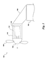
- FIG. 1 illustrates a wind turbine 100 arranged on a tower 102 having a hub 104 with blades 106.
- a generator 110 is provided on an extension 108 of the tower 102.
- the generator 110 includes a rotor assembly 112 and a stator assembly 114.
- An exemplary segmented stator assembly 114 is shown in more detail in FIGs. 2A and 2B .
- the example depicts the generator upstream of the tower 102, the generator location could be either upstream, downstream or on the tower, and the embodiments for stator segmentation discussed here apply to all such configurations.
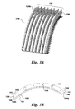
- FIG. 2A illustrates a diagrammatic view of a segmented stator according to an exemplary embodiment of the invention.
- the segmented stator assembly 114 includes stator segments or portions 116 each having stator laminations 118. In the example illustrated, four stator segments are shown. However, it is to be understood that the invention is not limited in this regard and that there can be any number of stator segments.
- FIG. 2B is a blown-up view of portion 119 of the segmented stator 114, which shows that each stator segment 116 includes stator laminations 118 each having a yoke or back iron 120 and stator teeth 122 defining stator openings 124.
- the stator openings 124 are provided to accommodate windings 136 (shown in FIG. 4 ).
- Each stator segment 116 includes structural plates (or support plates) 126.
- the structural plates 126 can include end plates 126a and 126b arranged exterior to intermediate or remaining structural plates 126 in an axial direction.
- the end plates 126a, 126b can be of the same or different thickness than the intermediate structural plates 126.
- the end plates 126a, 126b can be significantly thicker than the other structural plates 126 to provide for structural integrity when the stator segments 116 are assembled to form the segmented stator assembly 114.
- each of the structural plates 126 includes notch-like or tooth-like structures 128 formed on a portion of the structural plate 126 along an inner circumference.
- the structural plates 126 are embedded into the stator laminations 118, as shown in FIG. 4 , via the teeth 128.
- the structural plates 126 protrude radially outward beyond the stator core 118 to facilitate coupling of the structural plates to provide structural integrity to the stator segment 116.
- eight structural plates 126 are shown. However, it is to be understood that any number of structural plates 126 can be used depending on the design and application.
- the thickness and material of the structural plates 126 are of a size and material to minimize performance loss. The number and location of the structural plates depend upon the application and desired performance.
- the end plates 126a, 126b need not be embedded into the stator laminations and can be configured without the tooth-like structures 128.
- the structural plates 126 each include an opening 130 proximate each of the teeth 128 for receiving a securing member or a connector such as a tension rod or bolt, for example. Any suitable connector can be used and the opening can be arranged to accommodate the corresponding connector.
- the connector goes through the stator core 120 and the openings 130 in the structural plates 126.
- tension rods or through-bolts 138 secured by nuts 140 are used to hold the structural plates 126 together firmly via the openings 130.
- each of the structural plates 126 further includes openings 132 to receive additional connectors or stabilizing elements 148 such as pipes, I-beams, or some other suitable stabilizing elements to connect the structural plates 126 together.
- the additional connectors 148 provide support and rigidity to the stator segment 116 via the structural plates 126, which will provide structural integrity to the stator assembly 114 when the stator segments 116 are secured together.
- Each stator segment 116 may further include openings 134 to accommodate spacer elements 150 to provide another connection point for the structural plates 126.
- the spacer elements 150 can be any suitably rigid elements such as bolts, rivets or weldments, for example. In the exemplary embodiment shown in FIG. 6 , both the stabilizing elements 148 and the spacer elements 150 are used. However, the stabilizing elements 148 can be used alone or in combination with any number of spacer elements 150.
- each structural plate 126 includes end portions 142 arranged at the outside circumferential end of each of the structural plates 126.
- the end portions 142 are provided to couple the structural plates 126 in a stator segment 116 to the structural plates 126 of other stator segments 116 to form the stator assembly 114.
- the end portions 142 each include a tab portion 143 that extends radially beyond the remainder of the structural plate 126.
- the tab portions 143 can be arranged such that one tab portion 143 is set back from the circumferential end 144a of the structural plate 126, while the other tab portion 143 is set at the opposite circumferential end 144b.
- end portions 142 can be formed to accommodate a selected coupling structure.
- Each end portion 142 includes openings 146. These openings 146 are provided to facilitate securing the structural plate 126 of one stator segment 116 to the structural plate 126 of another stator segment 116.
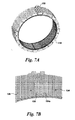
- FIG. 7A shows the stator segments 116 assembled to form the stator assembly 114.
- FIG. 7B is a blown-up view of section 152 of FIG. 7A .
- FIG. 8 illustrates a cross-sectional view of a stator segment 116 including splice plates 154a and 154b.
- the splice plates 154a and 154b are configured to correspond to the form of the end portions 142, as shown in FIG. 3B .
- the splice plates 154a and 154b include openings 156 that correspond to the openings 146 in the end portions 142 of the structural plates 126. As shown in FIG. 8 , the splice plates 154a and 154b are arranged axially on either side of the structural plates 126, including the end plates 126a, 126b that are to be coupled together.
- the splice plates 154a, 154b and the end portion 142 of adjacent structural plates 126 are coupled together by fastening elements such as bolts, for example. Other fastening means such as riveting, welding or brazing could also be used.
- Each of the structural plates 126 in the stator segment 116 is coupled to corresponding structural plates 126 of an adjacent stator segment 116 in this manner to provide a secure structure when the stator segments 116 are coupled together to form the stator assembly 114.
- the end plates 123 are separate from the structural plates 126 and are not embedded within the stator laminations 118.
- the end plates 123 are secured to supports 125 and stabilizing elements 148.
- This embodiment also includes spacer plates 127 that are embedded into the stator laminations and have a tooth-like shape similar to that of the structural plates 126.
- the spacer plates 127 provide radial cooling for the stator assembly.
- the embodiment is not limited to the use of spacer plates 127. They may be omitted or replaced by some other spacing element.
- Finger plates 121 are provided together with tension rod 137 to compress the laminations 118, spacer plates 127 and structural plates 126 together.
- Stator segments 116 according to this embodiment are joined together to form a stator assembly 114 using splice plates (not shown), similar to splice plates 154a, 154b.
- stator assembly 114 While end portions and splice plates have been used in the exemplary embodiments of the invention, one skilled in the art will appreciate that the structural plates 126 of adjacent stator segments 116 can be coupled together by any suitable mechanism to maintain the strength and structural integrity of the segmented stator assembly 114.
- FIG. 10 Another exemplary embodiment of a stator segment 116 is illustrated in FIG. 10 .
- the structural plates 129 protrude radially above the stator laminations 118.
- the height of the structural plates 129 is reduced in size and the structural plates 129 are coupled to the stabilizing elements 148 via hanging members 149.
- Hanging members 149 are coupled to each of structural plates 129 via bolts, welding, or some other suitable securing mechanism.
- the embodiment shown also includes spacer plates 127. However, the spacer plates 127 may be removed or replaced with other spacer elements.
- Finger plates 121 are shown to compress the laminations 118, spacer plates 127 and the structural plates 129 together via a tension rod or some other means. The structure is supported by end plates 123.
- the structural plates 129 include openings 300 on either end to facilitate connection to adjacent structure plates 129 of an adjacent stator segment 116 via splice plates (not shown), for example.
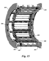
- the end plates 123 include openings 301 to facilitate coupling to end covers 304, as shown in FIG. 11 .
- the end plates 123 are bolted to the end covers 304.
- any other suitable connection means can be used to couple the stator segments 116 to the end covers 304.
- the end covers 304 can each be configured as a single, continuous element or as two or more elements that are connected.
- stator segment 200 includes end plates 210 and 212, compression plates 214 and 216, and stabilizing elements 218 such as pipes, for example, to couple all of the plates together to form a rigid structure for the stator segment 200.
- stabilizing elements 218 such as pipes, for example, to couple all of the plates together to form a rigid structure for the stator segment 200.
- each of the stabilizing elements 218 includes a dovetail bar 220.
- a dovetail 228 is secured to each of the dovetail bars 220.
- Each dovetail 228 engages with the stator laminations 234 (and with the supporting elements if utilized) and thus connects the laminations 234 to the stabilizing elements 218.
- each of the stator laminations 234 includes openings or notches 235 to accommodate the dovetails 228.
- the number of stabilizing elements 218 including dovetail bars 220 and dovetails 228 can be selected depending upon the particular configuration and desired stiffness of the stator segment.
- the number and location of notches 235 can be arranged to correspond to the number and location of the dovetails 228.
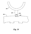
- the end plates 210, 212 and the compression plates 214, 216 are secured to the stabilizing elements 218, as shown in FIG. 14 . They may be integral to the stabilizing elements 218 or secured to the stabilizing elements 218 by welding, for example, or other suitable means.
- clamping plates 230 and 232 are secured to the compression plates 214 and 216, respectively. Any suitable means can be used to secure the clamping plates 230, 232 to the compression plates 214, 216.
- the stator laminations 234 are arranged between the clamping plates 230 and 232.
- the clamping plates 230, 232 and stator laminations 234 are secured together via tension rods 236, or other suitable securing mechanism. In this exemplary arrangement, there are no supporting or structural elements or plates embedded into the stator laminations 234, however such elements may also be used.
- the strength of the stator segment 200 is established by the end plates 210, 212, the compression plates 214, 216 and the stabilizing elements 218, which support the stator laminations 234.
- the end plates 210, 212 are of a thickness and material to provide strong support and structural integrity to the stator segments 200 as well as the stator assembly 114.
- the end plates 210 and 212 have end portions 238 having openings 240 similar to the end portions 142 and openings 146 shown 23in FIG. 3B .
- the end plates 210 and 212 of adjacent stator segments 200 are secured together via splice plates 242a and 242b in the same manner as the splice plates 154a, 154b.
- the splice plates 242a and 242b are configured to correspond to the form of the end portions 238.
- the splice plates 242a and 242b include openings 243 that correspond to the openings 240 in the end portions 238 of the end plates 210 and 212.
- the splice plates 242a and 242b are arranged axially on either side of the end plates 242a, 242b that are to be coupled together.
- the splice plates 242a, 242b and the end portion 238 of adjacent end plates 210, 212 are coupled together by fastening elements such as bolts, for example.
- Each of the end plates 210, 212 in the stator segment 200 is coupled to corresponding end plates 210, 212 of an adjacent stator segment 200 in this manner to provide a secure structure when the stator segments 200 are coupled together to form the stator assembly 114.
- the splice plates 242a, 242b can be of a larger size such that if there are only two stator segments 200, the splice plates 242a, 242b can be semicircle in size to provide the fullest support.
- the size of the splice plates can be designed to any suitable size.
- end plates 210, 212 of adjacent stator segments 200 can be coupled together by any suitable mechanism to maintain the strength and structural integrity of the segmented stator assembly 114.
- each stator segment 116 includes an outer shell 300 and an inner shell 302.
- the outer shell 300 includes openings 303, while the inner shell includes openings 305. These openings 303, 305 are provided to couple the stator segment 116 to outer covers or supports 314, 316.
- Webs 307 are arranged between the outer shell 300 and the inner shell 302 to provide support for the stator segment 116.
- Dovetail bars 306, each having a dovetail 308, are coupled to the inner shell 302.
- the outer shell 300, inner shell 302, webs 307, and the dovetail bars 306 are coupled together by welding. Any suitable method can be used for coupling these elements together.
- each of the stator laminations 234 includes openings or notches 235 to accommodate the dovetails 308.
- finger plates 312 are provided to compress the stator laminations 234 together via a tension rod 313 or some other tensioning element.
- the stator laminations 234 include openings 233 in the stator core or backbone 231 to provide for axial cooling of the stator segment 116.
- the embodiment is not limited to this arrangement, and the stator laminations 234 can be solid or include some other configuration.
- the stator segments 116 shown in FIGs. 19A and 19B are secured to outer covers or support structures 314 and 316, as shown in FIG. 20 .
- the support structures 314, 316 each include openings 318 to facilitate coupling to the stator segments 116.
- the openings 303 and 305 of the outer and inner shells 300, 302 are aligned with the openings 318 of the support structures 314, 316 to allow coupling by bolts or other suitable fastening members.
- the cover 314 includes a flange 314a along the straight edge, and similarly, the cover 316 includes a flange 316a along the straight edge.
- Each of the flanges 314a, 316a includes openings 317 to receive bolts or other fastening elements.
- the outer covers 314 and 316 are configured to house one half 320 of the stator assembly 114. More particularly, in the embodiment shown, four stator segments 116 are coupled to the covers 314 and 316 to form half of the stator assembly 114. The number of stator segments 116 arranged in the covers 314 and 316 will vary depending upon design and application to include one or more stator segments 116. Similarly, the configuration of the halves 320 may vary from being a single, continuous element to multiple elements combined together.
- FIG. 21 illustrates a fully assembled stator assembly 114 including the stator segments 116 shown in FIGs. 19A , 19B, and 20 .
- stator halves 320 are joined together by bolting the flanges 314a and 316a together via openings 317.
- the stator halves 320 are arranged in place around a hub 323. It should be understood that while two halves are disclosed, the support structures can be arranged in any configuration from a single, continuous structure to multiple structures.
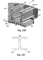
- FIGs. 22A-22C A stator segment 116 according to another exemplary embodiment is shown in FIGs. 22A-22C .
- This embodiment includes end plates 400 and split I-beams 401 each having sides 402 and 404 that are welded to the end plates 400.
- the sides 402, 404 of each split I-beam 401 could be coupled to the end plates 400 by any suitable fastening or securing mechanism.
- Dovetail bars 406 are provided to couple the split I-beams 401 to corresponding dovetails 408.
- the dovetail bars 406 each include openings 409 to accommodate dovetail bolts 410 the couple the dovetail bars 406 to the dovetails 408.
- the stator laminations 234 include openings 235 to accommodate the dovetails 408.
- Finger plates 412 are provided to compress the stator laminations 234 together via a tension rod 414, for example.
- the stator segment 116 is secured to support structures 314 and 316 as shown in FIG. 20 to form stator halve 320.
- One or more stator segments 116 are arranged within the stator halve 320.
- Stator halves 320 are arranged on a hub 323 and coupled together to form the stator assembly as shown in FIG. 21 . It should be understood that while two halves are disclosed, the support structures can be arranged in any configuration from a single, continuous structure to multiple structures.
- openings 415 are provided to reduce the weight of the stator segment 116.
- embodiments of the invention can have different configurations.
- FIG. 22B illustrates a cut-away view of the embodiment shown in FIG. 22A .
- the end portions of the sides 402, 404 in each of the I-beams 401 are coupled together by a lower element 416 and an upper element 417.
- the sides 402, 404 and the elements 416, 417 are welded together or coupled together by any suitable means.
- the lower and upper elements 416, 417 each include openings 424 that align with the openings 409 in each of the dovetail bars 406.
- the openings 424 enable access to the dovetail bolts 410, respectively.
- the dovetail bolts 410 hold the dovetails 408 in place while the stator laminations 234 are arranged onto the dovetails 408.
- stator laminations 234 are tightened via openings 424 to secure the stator laminations 234 in place in the stator segment.
- the stator laminations 234 each include openings 418 and 420 to facilitate axial cooling.
- other stator lamination configurations can be implemented.
- FIGs. 23A and 23B Another exemplary embodiment of a stator segment is shown in FIGs. 23A and 23B .
- the stator segment 116 includes a barrel shaped element 500 having openings 503, 505 and 512. Openings 503 provide for coupling the barrel 500 to support structures or covers 314 and 316 via bolts or some other means. Openings 505 are provided to couple adjacent stator segments 116 together via bolts or other securing element. Openings 512 are provided to enable dovetail bolts 506 to secure dovetails 504 to the barrel 500.
- finger plates 508 are provided to compress stator laminations 234 together via a tension rod 510, for example.
- the stator laminations 234 include openings 235 to accommodate the dovetails 504.
- the dovetail bolts 506 hold the dovetails 504 in place while the stator laminations 234 are arranged onto the dovetails 504. Once all of the stator laminations 234 are in place, the dovetail bolts 506 are tightened via openings 512 to secure the stator laminations 234 in place in the stator segment.
- the stator laminations 234 each includes openings 514 facilitate axial cooling. However, other stator lamination configurations can be implemented. In some embodiments, openings 516 can also be provided to facilitate liquid cooling.
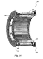
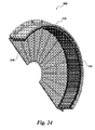
- FIG. 24 illustrates a cut-away view of a portion of a stator assembly or stator assembly half 520 including the barrel stator segments 116 illustrated in FIGs. 23A and 23B .
- two stator segments 116 are secured to the support structure 316.
- any number of stator segments can be coupled to the stator assembly portion 520.
- the support structures 314 (not shown in FIG. 24 ) and 316 can have any number of portions to support one or more stator segments based on the design and application.
- the barrel 500 is bolted to the support structures 314 (not shown in FIG. 24 ) and 316.
- the stator segments 116 are bolted together via openings 505.
- the stator portion 520 is coupled to another stator portion 520 to form a complete stator assembly 114.
- concentrated winding are used.
- the stator coils are arranged concentrically, and wound around each of the stator teeth.
- the stator coils are arranged concentrically, and wound around alternate ones of the stator teeth.
- the concentrated winding 136 is wound around the stator tooth and the number of stator slots per rotor pole per phase are ⁇ 1, i.e. it is a fractional slot winding.
- the number of slots per rotor pole per phase is equal to or greater than unity.
- the interaction of rotor poles and the slotted stator for the fractional slot winding results in various MMF harmonics, which are exploited to yield a harmonic coupled machine.
- the concentrated winding with harmonic coupling offers a higher fill factor for the coils, better aspect ratio of stator teeth, and shorter end windings, which combine to enable higher torque density with relatively high pole count.
- a 2/7 slot-per-pole-per phase winding design can be used to build a harmonically coupled machine with seven times the number of poles employing the 7 th harmonic of the MMF distribution for the same number of coils as a two slots per-pole-per-phase design. This results in lower flux per pole, potentially by up to that ratio, and a corresponding reduction in rotor and stator back iron needed to carry EM flux.
- this machine type is desirable for a segmented stator arrangement.
- a segmented stator assembly includes stator segments that provide for more cost effective shipping and installation while maintaining the strength and structural integrity of the large assemblies to achieve desired performance requirements.
- the stator segments can be of a size that can be shipped in industry standard shipping containers, thereby reducing the cost of shipping.
- the electric machines discussed herein may be well suited for wind turbine applications. However, such machines may be employed in a variety of other applications.
Abstract
Description
- Generators have been widely used in a variety of applications including aircraft, automobiles and turbines. Generators typically include a stator and a rotor that work together to produce electricity. Wind turbines have received increased attention recently as an environmentally safe alternative energy source. Wind turbines convert the kinetic energy of the wind into mechanical power and then the mechanical power drives the generator to produce electricity.
- Offshore wind turbines typically have ratings of 3MW and higher, necessitated by the economics of wind energy production. Also offshore turbines employ a direct drive generator to improve reliability, unlike most land based utility scale wind turbines that utilize a geared generator. These ratings and the fact that the generator is directly driven manifests into a very large size and weight. A machine greater than 4m in diameter is difficult and costly to transport by conventional means and necessitates segmentation.
- Alternatively, a 3MW machine could be made within a 4m diameter limit by making it axially longer or utilizing a double-sided configuration. Both of these options present challenges. An axially longer machine weighs significantly more than a shorter length larger diameter machine whereas a double-sided configuration presents significant manufacturing complexity. While the segmented stator structures facilitate cost and transport, particularly when designed to accommodate conventional rail or road shipping constraints, they are difficult to manufacture and assemble at site.
- For these and other reasons, there is a need for the present invention.
- According to one aspect of the present invention, a stator assembly includes a segmented stator having stator portions. Each stator portion includes a support structure and dovetails, each coupled to the support structure by adjustable elements. The stator portion also includes stator laminations, where each of the laminations has openings to engage with the dovetails. Connectors are provided to connect the stator portions of the segmented stator together.
- The nature and various additional features of the invention will appear more fully upon consideration of the illustrative embodiments of the invention which are schematically set forth in the figures. Like reference numerals represent corresponding parts.
-
FIG. 1 illustrates a wind turbine having a stator assembly according to an exemplary embodiment of the invention; -
FIG. 2A illustrates a diagrammatic view of a stator assembly according to an exemplary embodiment of the present invention; -
FIG. 2B illustrates a blown-up view of a portion of the stator assembly shown inFIG. 2A ; -
FIG. 3A illustrates a top view of a stator segment or portion of a stator assembly according to an exemplary embodiment of the present invention; -
FIG. 3B illustrates a cross-sectional view of one of the support plates shown inFIG. 2A according to an exemplary embodiment of the present invention; -
FIG. 4 illustrates a cross-sectional view of a structural plate in the stator segment shown inFIG. 3A ; -
FIG. 5 illustrates a side view of the structural plates in the stator segment shown inFIG. 3A according to an exemplary embodiment of the present invention; -
FIG. 6 illustrates a top view of a stator segment or portion of a stator assembly according to another exemplary embodiment of the present invention; -
FIG. 7A illustrates a cross-sectional view of a segmented stator assembly having support plates according to an exemplary embodiment of the invention; -
FIG. 7B illustrates a blown-up view of a portion of the segmented stator assembly shown inFIG. 7A ; -
FIG. 8 illustrates a cross-sectional view of the stator segment having support plates and splice plates according to an exemplary embodiment of the present invention; -
FIG. 9 illustrates a diagrammatic view of a stator segment of a stator assembly according to a further exemplary embodiment of the invention; -
FIG. 10 illustrates a diagrammatic view of yet another exemplary embodiment of a stator segment of a stator assembly; -
FIG. 11 illustrates another diagrammatic view of the exemplary embodiment shown inFIG. 10 ; -
FIG. 12 illustrates a diagrammatic view of a stator segment of a stator assembly according to a further exemplary embodiment of the present invention; -
FIG. 13 illustrates stabilizing elements according to an exemplary embodiment of the invention; -
FIG. 14 illustrates a cross-sectional view of the stabilizing elements according to an exemplary embodiment of the invention; -
FIG. 15 illustrates a support structure for a stator segment according to an exemplary embodiment of the present invention; -
FIG. 16 illustrates the support structure for a stator segment a stator segment according to an exemplary embodiment of the invention; -
FIG. 17 illustrates a cross-sectional view of an end plate according to an exemplary embodiment of the invention; -
FIG. 18 illustrates connecting elements according to an exemplary embodiment of the present invention; -
FIGs. 19A and19B illustrate a cross-sectional view and a diagrammatic view of a stator segment of a stator assembly according to another exemplary embodiment; -
FIG. 20 illustrates an exemplary embodiment of a support structure for the embodiment shown inFIGs. 19A and19B ; -
FIG. 21 illustrates an exemplary embodiment of an assembled stator assembly of the stator segment and the support structure shown inFIGs. 19A ,19B, and 20 ; -
FIGs. 22A-22C illustrate a cross-sectional view and a diagrammatic view of yet another exemplary embodiment of a stator segment of a stator assembly; -
FIGs. 23A and23B illustrate a cross-sectional view and a diagrammatic view of a stator segment of a stator assembly according to a further exemplary embodiment; and -
FIG. 24 illustrates an exemplary stator segment and support the stator segment shown inFIGs. 23A and23B . - While the above-identified drawing figures set forth alternative embodiments, other embodiments of the present invention are also contemplated, as noted in the discussion. In all cases, this disclosure presents illustrated embodiments of the present invention by way of representation and not limitation. Numerous other modifications and embodiments can be devised by those skilled in the art which fall within the scope and spirit of the principles of this invention.
- Embodiments of the present invention will be explained in further detail by making reference to the accompanying drawings, which do not limit the scope of the invention in any way.
- Exemplary embodiments of the invention disclosed herein are shown in the context of a generator for a wind turbine. However, this is only an example for the purpose of description. It is to be understood that the stator assembly according to embodiments of the invention can be used in any generator for electric machines. In addition, the generator can be a direct drive generator or any other generator used for electric machines.
-
FIG. 1 illustrates awind turbine 100 arranged on atower 102 having ahub 104 withblades 106. Agenerator 110 is provided on anextension 108 of thetower 102. Thegenerator 110 includes arotor assembly 112 and astator assembly 114. An exemplary segmentedstator assembly 114 is shown in more detail inFIGs. 2A and 2B . Although the example depicts the generator upstream of thetower 102, the generator location could be either upstream, downstream or on the tower, and the embodiments for stator segmentation discussed here apply to all such configurations. -
FIG. 2A illustrates a diagrammatic view of a segmented stator according to an exemplary embodiment of the invention. Thesegmented stator assembly 114 includes stator segments orportions 116 each havingstator laminations 118. In the example illustrated, four stator segments are shown. However, it is to be understood that the invention is not limited in this regard and that there can be any number of stator segments.FIG. 2B is a blown-up view ofportion 119 of thesegmented stator 114, which shows that eachstator segment 116 includesstator laminations 118 each having a yoke or backiron 120 andstator teeth 122 definingstator openings 124. Thestator openings 124 are provided to accommodate windings 136 (shown inFIG. 4 ). - One of the
stator segments 116 is shown inFIG. 3A . Eachstator segment 116 includes structural plates (or support plates) 126. Thestructural plates 126 can includeend plates structural plates 126 in an axial direction. Theend plates structural plates 126. For example, theend plates structural plates 126 to provide for structural integrity when thestator segments 116 are assembled to form thesegmented stator assembly 114. - As shown in
FIG. 3B , each of thestructural plates 126 includes notch-like or tooth-like structures 128 formed on a portion of thestructural plate 126 along an inner circumference. Thestructural plates 126 are embedded into thestator laminations 118, as shown inFIG. 4 , via theteeth 128. Thestructural plates 126 protrude radially outward beyond thestator core 118 to facilitate coupling of the structural plates to provide structural integrity to thestator segment 116. In the drawings, eightstructural plates 126 are shown. However, it is to be understood that any number ofstructural plates 126 can be used depending on the design and application. The thickness and material of thestructural plates 126 are of a size and material to minimize performance loss. The number and location of the structural plates depend upon the application and desired performance. In other embodiments, theend plates like structures 128. - Referring to
FIGs. 3B and4 , thestructural plates 126 each include anopening 130 proximate each of theteeth 128 for receiving a securing member or a connector such as a tension rod or bolt, for example. Any suitable connector can be used and the opening can be arranged to accommodate the corresponding connector. The connector goes through thestator core 120 and theopenings 130 in thestructural plates 126. Referring toFIG. 5 , tension rods or through-bolts 138 secured bynuts 140 are used to hold thestructural plates 126 together firmly via theopenings 130. - Referring to
FIG. 3B , each of thestructural plates 126 further includesopenings 132 to receive additional connectors or stabilizingelements 148 such as pipes, I-beams, or some other suitable stabilizing elements to connect thestructural plates 126 together. Theadditional connectors 148 provide support and rigidity to thestator segment 116 via thestructural plates 126, which will provide structural integrity to thestator assembly 114 when thestator segments 116 are secured together. Eachstator segment 116 may further includeopenings 134 to accommodatespacer elements 150 to provide another connection point for thestructural plates 126. Thespacer elements 150 can be any suitably rigid elements such as bolts, rivets or weldments, for example. In the exemplary embodiment shown inFIG. 6 , both the stabilizingelements 148 and thespacer elements 150 are used. However, the stabilizingelements 148 can be used alone or in combination with any number ofspacer elements 150. - While exemplary embodiments of the invention have been illustrated with multiple sets of
openings structural plates 126 of thestator segment 116, or any combination of the sets of openings and respective connectors can be used. The location of the sets of openings can be arranged in any manner suitable to the application and configuration of the structural plates. - As shown in
FIG. 3B , eachstructural plate 126 includesend portions 142 arranged at the outside circumferential end of each of thestructural plates 126. Theend portions 142 are provided to couple thestructural plates 126 in astator segment 116 to thestructural plates 126 ofother stator segments 116 to form thestator assembly 114. In the exemplary embodiment shown, for eachstructural plate 126, theend portions 142 each include atab portion 143 that extends radially beyond the remainder of thestructural plate 126. Thetab portions 143 can be arranged such that onetab portion 143 is set back from thecircumferential end 144a of thestructural plate 126, while theother tab portion 143 is set at the oppositecircumferential end 144b. However, embodiments of the invention are not limited in this regard and theend portions 142 can be formed to accommodate a selected coupling structure. Eachend portion 142 includesopenings 146. Theseopenings 146 are provided to facilitate securing thestructural plate 126 of onestator segment 116 to thestructural plate 126 of anotherstator segment 116. - In the exemplary embodiment shown in
FIGs. 7A, 7B and8 , thestructural plates 126 are secured together viasplice plates FIG. 7A shows thestator segments 116 assembled to form thestator assembly 114.FIG. 7B is a blown-up view ofsection 152 ofFIG. 7A .FIG. 8 illustrates a cross-sectional view of astator segment 116 includingsplice plates splice plates end portions 142, as shown inFIG. 3B . Thesplice plates openings 156 that correspond to theopenings 146 in theend portions 142 of thestructural plates 126. As shown inFIG. 8 , thesplice plates structural plates 126, including theend plates splice plates end portion 142 of adjacentstructural plates 126 are coupled together by fastening elements such as bolts, for example. Other fastening means such as riveting, welding or brazing could also be used. Each of thestructural plates 126 in thestator segment 116 is coupled to correspondingstructural plates 126 of anadjacent stator segment 116 in this manner to provide a secure structure when thestator segments 116 are coupled together to form thestator assembly 114. - In the embodiment shown in
FIG. 9 , theend plates 123 are separate from thestructural plates 126 and are not embedded within thestator laminations 118. Theend plates 123 are secured tosupports 125 and stabilizingelements 148. This embodiment also includesspacer plates 127 that are embedded into the stator laminations and have a tooth-like shape similar to that of thestructural plates 126. Thespacer plates 127 provide radial cooling for the stator assembly. The embodiment is not limited to the use ofspacer plates 127. They may be omitted or replaced by some other spacing element.Finger plates 121 are provided together withtension rod 137 to compress thelaminations 118,spacer plates 127 andstructural plates 126 together.Stator segments 116 according to this embodiment are joined together to form astator assembly 114 using splice plates (not shown), similar to spliceplates - While end portions and splice plates have been used in the exemplary embodiments of the invention, one skilled in the art will appreciate that the
structural plates 126 ofadjacent stator segments 116 can be coupled together by any suitable mechanism to maintain the strength and structural integrity of thesegmented stator assembly 114. - Another exemplary embodiment of a
stator segment 116 is illustrated inFIG. 10 . In this arrangement, thestructural plates 129 protrude radially above thestator laminations 118. However, the height of thestructural plates 129 is reduced in size and thestructural plates 129 are coupled to the stabilizingelements 148 via hangingmembers 149. Hangingmembers 149 are coupled to each ofstructural plates 129 via bolts, welding, or some other suitable securing mechanism. The embodiment shown also includesspacer plates 127. However, thespacer plates 127 may be removed or replaced with other spacer elements.Finger plates 121 are shown to compress thelaminations 118,spacer plates 127 and thestructural plates 129 together via a tension rod or some other means. The structure is supported byend plates 123. In this embodiment, thestructural plates 129 includeopenings 300 on either end to facilitate connection toadjacent structure plates 129 of anadjacent stator segment 116 via splice plates (not shown), for example. Theend plates 123 includeopenings 301 to facilitate coupling to endcovers 304, as shown inFIG. 11 . Theend plates 123 are bolted to the end covers 304. However, any other suitable connection means can be used to couple thestator segments 116 to the end covers 304. The end covers 304 can each be configured as a single, continuous element or as two or more elements that are connected. - Another exemplary embodiment of a stator segment is shown in
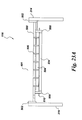
FIG. 12 . In this embodiment, thestator segment 200 includesend plates compression plates elements 218 such as pipes, for example, to couple all of the plates together to form a rigid structure for thestator segment 200. In this exemplary embodiment, there are no structures embedded in the stator laminations. - Referring to
FIGs. 13 and14 , each of the stabilizingelements 218 includes adovetail bar 220. Adovetail 228 is secured to each of the dovetail bars 220. Eachdovetail 228 engages with the stator laminations 234 (and with the supporting elements if utilized) and thus connects thelaminations 234 to the stabilizingelements 218. As shown inFIG. 14 , in this exemplary embodiment, each of thestator laminations 234 includes openings ornotches 235 to accommodate the dovetails 228. The number of stabilizingelements 218 including dovetail bars 220 and dovetails 228 can be selected depending upon the particular configuration and desired stiffness of the stator segment. The number and location ofnotches 235 can be arranged to correspond to the number and location of the dovetails 228. Theend plates compression plates elements 218, as shown inFIG. 14 . They may be integral to the stabilizingelements 218 or secured to the stabilizingelements 218 by welding, for example, or other suitable means. - Referring to
FIGs. 15 and16 , clampingplates compression plates plates compression plates plates plates stator laminations 234 are secured together viatension rods 236, or other suitable securing mechanism. In this exemplary arrangement, there are no supporting or structural elements or plates embedded into thestator laminations 234, however such elements may also be used. The strength of thestator segment 200 is established by theend plates compression plates elements 218, which support thestator laminations 234. In this exemplary embodiment, theend plates stator segments 200 as well as thestator assembly 114. - Referring to
FIGs. 17 and 18 , theend plates end portions 238 havingopenings 240 similar to theend portions 142 andopenings 146 shown 23inFIG. 3B . As shown inFIG. 15 , theend plates adjacent stator segments 200 are secured together viasplice plates splice plates splice plates end portions 238. Thesplice plates openings 243 that correspond to theopenings 240 in theend portions 238 of theend plates splice plates end plates splice plates end portion 238 ofadjacent end plates end plates stator segment 200 is coupled tocorresponding end plates adjacent stator segment 200 in this manner to provide a secure structure when thestator segments 200 are coupled together to form thestator assembly 114. In this exemplary embodiment, thesplice plates stator segments 200, thesplice plates - While end portions and splice plates have been used in the exemplary embodiments, one skilled in the art will appreciate that the
end plates adjacent stator segments 200 can be coupled together by any suitable mechanism to maintain the strength and structural integrity of thesegmented stator assembly 114. - Another exemplary embodiment of a stator segment is shown in
FIGs. 19A and19B . In this embodiment, eachstator segment 116 includes anouter shell 300 and aninner shell 302. Theouter shell 300 includesopenings 303, while the inner shell includesopenings 305. Theseopenings stator segment 116 to outer covers or supports 314, 316.Webs 307 are arranged between theouter shell 300 and theinner shell 302 to provide support for thestator segment 116. Dovetail bars 306, each having adovetail 308, are coupled to theinner shell 302. Theouter shell 300,inner shell 302,webs 307, and the dovetail bars 306 are coupled together by welding. Any suitable method can be used for coupling these elements together. As in the embodiment shown inFIG. 14 , each of thestator laminations 234 includes openings ornotches 235 to accommodate the dovetails 308. In this embodiment,finger plates 312 are provided to compress thestator laminations 234 together via atension rod 313 or some other tensioning element. Referring toFIG. 19B , thestator laminations 234 includeopenings 233 in the stator core orbackbone 231 to provide for axial cooling of thestator segment 116. However, the embodiment is not limited to this arrangement, and thestator laminations 234 can be solid or include some other configuration. - The
stator segments 116 shown inFIGs. 19A and19B are secured to outer covers orsupport structures FIG. 20 . Thesupport structures openings 318 to facilitate coupling to thestator segments 116. Theopenings inner shells openings 318 of thesupport structures cover 314 includes aflange 314a along the straight edge, and similarly, thecover 316 includes aflange 316a along the straight edge. Each of theflanges openings 317 to receive bolts or other fastening elements. In this embodiment, the outer covers 314 and 316 are configured to house onehalf 320 of thestator assembly 114. More particularly, in the embodiment shown, fourstator segments 116 are coupled to thecovers stator assembly 114. The number ofstator segments 116 arranged in thecovers more stator segments 116. Similarly, the configuration of thehalves 320 may vary from being a single, continuous element to multiple elements combined together.FIG. 21 illustrates a fully assembledstator assembly 114 including thestator segments 116 shown inFIGs. 19A ,19B, and 20 . The stator halves 320 are joined together by bolting theflanges openings 317. The stator halves 320 are arranged in place around ahub 323. It should be understood that while two halves are disclosed, the support structures can be arranged in any configuration from a single, continuous structure to multiple structures. - A
stator segment 116 according to another exemplary embodiment is shown inFIGs. 22A-22C . This embodiment includesend plates 400 and split I-beams 401 each havingsides end plates 400. Thesides beam 401 could be coupled to theend plates 400 by any suitable fastening or securing mechanism. Dovetail bars 406 are provided to couple the split I-beams 401 to corresponding dovetails 408. The dovetail bars 406 each include openings 409 to accommodatedovetail bolts 410 the couple the dovetail bars 406 to the dovetails 408. The stator laminations 234 includeopenings 235 to accommodate the dovetails 408.Finger plates 412 are provided to compress thestator laminations 234 together via atension rod 414, for example. As in the embodiment shown inFIGs. 19A and19B , thestator segment 116 is secured to supportstructures FIG. 20 to form stator halve 320. One ormore stator segments 116 are arranged within the stator halve 320. Stator halves 320 are arranged on ahub 323 and coupled together to form the stator assembly as shown inFIG. 21 . It should be understood that while two halves are disclosed, the support structures can be arranged in any configuration from a single, continuous structure to multiple structures. In the embodiment shown,openings 415 are provided to reduce the weight of thestator segment 116. However, embodiments of the invention can have different configurations. -
FIG. 22B illustrates a cut-away view of the embodiment shown inFIG. 22A . The end portions of thesides beams 401 are coupled together by alower element 416 and anupper element 417. Thesides elements upper elements openings 424 that align with the openings 409 in each of the dovetail bars 406. Theopenings 424 enable access to thedovetail bolts 410, respectively. During assembly, thedovetail bolts 410 hold the dovetails 408 in place while thestator laminations 234 are arranged onto the dovetails 408. Once all of thestator laminations 234 are in place, thedovetail bolts 410 are tightened viaopenings 424 to secure thestator laminations 234 in place in the stator segment. In the embodiment shown, thestator laminations 234 each includeopenings - Another exemplary embodiment of a stator segment is shown in
FIGs. 23A and23B . Thestator segment 116 includes a barrel shapedelement 500 havingopenings Openings 503 provide for coupling thebarrel 500 to support structures or covers 314 and 316 via bolts or some other means.Openings 505 are provided to coupleadjacent stator segments 116 together via bolts or other securing element.Openings 512 are provided to enabledovetail bolts 506 to secure dovetails 504 to thebarrel 500. In this embodiment,finger plates 508 are provided to compressstator laminations 234 together via atension rod 510, for example. The stator laminations 234 includeopenings 235 to accommodate the dovetails 504. During assembly, thedovetail bolts 506 hold the dovetails 504 in place while thestator laminations 234 are arranged onto the dovetails 504. Once all of thestator laminations 234 are in place, thedovetail bolts 506 are tightened viaopenings 512 to secure thestator laminations 234 in place in the stator segment. In the embodiment shown, thestator laminations 234 each includesopenings 514 facilitate axial cooling. However, other stator lamination configurations can be implemented. In some embodiments,openings 516 can also be provided to facilitate liquid cooling. -
FIG. 24 illustrates a cut-away view of a portion of a stator assembly orstator assembly half 520 including thebarrel stator segments 116 illustrated inFIGs. 23A and23B . In this embodiment, twostator segments 116 are secured to thesupport structure 316. However, any number of stator segments can be coupled to thestator assembly portion 520. In addition, the support structures 314 (not shown inFIG. 24 ) and 316 can have any number of portions to support one or more stator segments based on the design and application. Thebarrel 500 is bolted to the support structures 314 (not shown inFIG. 24 ) and 316. In addition, thestator segments 116 are bolted together viaopenings 505. Thestator portion 520 is coupled to anotherstator portion 520 to form acomplete stator assembly 114. - The exemplary embodiments shown, concentrated winding are used. In some embodiments, the stator coils are arranged concentrically, and wound around each of the stator teeth. In other embodiments, the stator coils are arranged concentrically, and wound around alternate ones of the stator teeth. The concentrated winding 136 is wound around the stator tooth and the number of stator slots per rotor pole per phase are <1, i.e. it is a fractional slot winding. As opposed to a conventional stator, wherein the number of slots per rotor pole per phase is equal to or greater than unity. The interaction of rotor poles and the slotted stator for the fractional slot winding results in various MMF harmonics, which are exploited to yield a harmonic coupled machine. The concentrated winding with harmonic coupling offers a higher fill factor for the coils, better aspect ratio of stator teeth, and shorter end windings, which combine to enable higher torque density with relatively high pole count. For example, a 2/7 slot-per-pole-per phase winding design can be used to build a harmonically coupled machine with seven times the number of poles employing the 7th harmonic of the MMF distribution for the same number of coils as a two slots per-pole-per-phase design. This results in lower flux per pole, potentially by up to that ratio, and a corresponding reduction in rotor and stator back iron needed to carry EM flux. Also, this machine type is desirable for a segmented stator arrangement.
- In the embodiments disclosed herein, a segmented stator assembly includes stator segments that provide for more cost effective shipping and installation while maintaining the strength and structural integrity of the large assemblies to achieve desired performance requirements. The stator segments can be of a size that can be shipped in industry standard shipping containers, thereby reducing the cost of shipping.
- The electric machines discussed herein may be well suited for wind turbine applications. However, such machines may be employed in a variety of other applications.
- While the invention has been described in terms of various specific embodiments, those skilled in the art will recognize that the invention can be practiced with modification within the spirit and scope of the claims.
- Various aspects and embodiments of the present invention are defined by the following numbered clauses:
- 1. A stator assembly, comprising:
- a segmented stator having stator portions, wherein each stator portion comprises:
- a support structure having a main portion and first and second end portions;
- dovetails, each coupled to the support structure by adjustable elements; and
- stator laminations, each having openings to engage with the dovetails, respectively; and
- connectors to connect the stator portions of the segmented stator together.
- a segmented stator having stator portions, wherein each stator portion comprises:
- 2. The stator assembly of clause 1, wherein the main portion of the support structure comprises rows of openings corresponding to the dovetails, respectively, wherein the openings in each row receive one of the adjustable elements to secure the dovetails to the support structure.
- 3. The stator assembly of any preceding clause, wherein each of the adjustable elements is a bolt.
- 4. The stator assembly of any preceding clause, further comprising:
- inner and outer plates having openings, wherein the stator laminations are arranged between the inner and outer plates; and
- securing elements arranged in the openings of the inner and outer plates for securing the stator laminations together.
- 5. The stator assembly of any preceding clause, wherein the securing elements are tension rods.
- 6. The stator assembly of any preceding clause, wherein each of the stator laminations further comprises secondary openings to provide for liquid cooling.
- 7. The stator assembly of any preceding clause, wherein the support structure further comprises inner and outer sides that each extend upward from the main portion, each of the inner and outer sides comprising openings to receive securing elements.
- 8. The stator assembly of any preceding clause, further comprising inner and outer covers having an arcuate structure for receiving one or more stator portions, wherein the inner and outer covers each comprise openings that align with the openings of the inner and outer sides of the support structure, the one or more stator portions being secured to the inner and outer covers via the securing elements.
- 9. The stator assembly of any preceding clause, wherein the inner and outer covers include radial edges having flanges to enable the inner and outer covers of one portion of the stator assembly to be coupled to the inner and outer covers of another portion of the stator assembly.
- 10. A stator assembly, comprising:
- a segmented stator having stator portions, wherein each stator portion comprises:
- stator laminations;
- end plates arranged axially on opposing sides of the stator portion;
- structural plates, arranged interior to the end plates, each having a portion that is embedded within the stator laminations, wherein the portion of each of the structural plates comprises notch-like structures;
- stabilizing elements coupling the end plates and the structural plates together; and
- hanging members coupled to each of the structural plates to support the structural plates on the stabilizing elements; and
- connectors to connect the stator portions of the segmented stator together.
- a segmented stator having stator portions, wherein each stator portion comprises:
- 11. The stator assembly of any preceding clause, wherein each of the structural plates and each of the hanging members comprises openings to receive securing members to secure the hanging members to the structural plates.
- 12. The stator assembly of any preceding clause, wherein each of the end plates comprises a portion having notch-like structures that is embedded within the stator laminations.
- 13. The stator assembly of any preceding clause, wherein the portion of each of the structural plates comprises openings to receive securing members respectively to secure the structural plates together.
- 14. The stator assembly of any preceding clause, wherein each of the stabilizing elements comprises a pipe.
- 15. The stator assembly of any preceding clause, wherein each of the connectors comprises splice plates arranged axially on either side of each of the end plates, the splice plates and the end plates comprising openings to accommodate securing elements, respectively, to secure the end plates of adjacent stator portions together.
- 16. The stator assembly of any preceding clause, wherein the connectors further comprise splice plates arranged axially on either side of each of the structural plates, the structural plates comprising openings to accommodate the securing elements, respectively, to secure the structural plates of adjacent stator portions together.
- 17. The stator assembly of any preceding clause, further comprising spacer plates having a portion embedded within the stator laminations, wherein the portion of each of the spacer plates and the portion of each of the structural plates comprises notch structures creating openings to allow a cooling medium to flow between the notch structures to provide radial cooling of the stator windings.
- 18. The stator assembly of any preceding clause, wherein the stator assembly is coupled to inner and outer covers via the end plates.
- 19. A stator assembly, comprising:
- a segmented stator having stator portions, wherein each stator portion comprises:
- end plates;
- support structures coupled to the end plates;
- dovetails, each coupled to the support structures by adjustable elements; and
- stator laminations, each having openings to engage with the dovetails, respectively; and
- connectors to connect the stator portions of the segmented stator together.
- a segmented stator having stator portions, wherein each stator portion comprises:
- 20. The stator assembly of any preceding clause, wherein the support structures each comprise:
- a split I-beam arrangement having coupling elements to secure the split I-beam arrangement, wherein the coupling elements comprise openings for receiving the adjustable elements coupling the dovetails to the support structures.
- 21. The stator assembly of any preceding clause, wherein each of the connectors comprises splice plates arranged axially on either side of each of the end plates, the splice plates and the end plates comprising openings to accommodate securing elements, respectively, to secure the end plates of adjacent stator portions together.
Claims (9)
- A stator assembly (114), comprising:a segmented stator having stator portions (116), wherein each stator portion (116) comprises:a support structure (507) having a main portion (500) and first and second end portions (501);dovetails (504), each coupled to the support structure by adjustable elements (506); andstator laminations (234), each having openings (235) to engage with the dovetails (504), respectively; andconnectors (505) to connect the stator portions of the segmented stator together.
- The stator assembly (114) of claim 1, wherein the main portion (500) of the support structure (507) comprises rows of openings (512) corresponding to the dovetails (504), respectively, wherein the openings (512) in each row receive one of the adjustable elements (506) to secure the dovetails (504) to the support structure (507).
- The stator assembly (114) of any preceding claim, wherein each of the adjustable elements (506) is a bolt.
- The stator assembly (114) of any preceding claim, further comprising:inner and outer plates (314, 316) having openings (318), wherein the stator laminations (234) are arranged between the inner and outer plates (314, 316); andsecuring elements arranged in the openings (318) of the inner and outer plates (314, 316) for securing the stator laminations (234) together.
- The stator assembly (114) of any preceding claim, wherein the securing elements are bolts.
- The stator assembly (114) of any preceding claim, wherein each of the stator laminations (234) further comprises secondary openings (516) to provide for liquid cooling.
- The stator assembly (114) of any preceding claim, wherein the support structure (507) further comprises inner and outer sides (502) that each extend upward from the main portion (500), each of the inner and outer sides (502) comprising openings (503) to receive securing elements.
- The stator assembly (114) of any preceding claim, further comprising inner and outer covers (314, 316) having an arcuate structure for receiving one or more stator portions (116), wherein the inner and outer covers (314, 316) each comprise openings (318) that align with the openings (503) of the inner and outer sides of the support structure (507), the one or more stator portions (116) being secured to the inner and outer covers (314, 316) via the securing elements.
- The stator assembly (114) of any preceding claim, wherein the inner and outer covers (314, 316) include radial edges having flanges (314a, 316a) to enable the inner and outer covers (314, 316) of one portion (320, 520) of the stator assembly to be coupled to the inner and outer covers (314, 316) of another portion (320, 520) of the stator assembly (114).
Applications Claiming Priority (2)
| Application Number | Priority Date | Filing Date | Title |
|---|---|---|---|
| US12/871,276 US8319389B2 (en) | 2010-08-30 | 2010-08-30 | Segmented stator assembly |
| US12/916,258 US8492951B2 (en) | 2010-08-30 | 2010-10-29 | Segmented stator assembly |
Publications (3)
| Publication Number | Publication Date |
|---|---|
| EP2424077A2 true EP2424077A2 (en) | 2012-02-29 |
| EP2424077A3 EP2424077A3 (en) | 2016-10-26 |
| EP2424077B1 EP2424077B1 (en) | 2021-05-19 |
Family
ID=44857691
Family Applications (1)
| Application Number | Title | Priority Date | Filing Date |
|---|---|---|---|
| EP11177347.9A Active EP2424077B1 (en) | 2010-08-30 | 2011-08-12 | Segmented stator assembly |
Country Status (5)
| Country | Link |
|---|---|
| US (1) | US8492951B2 (en) |
| EP (1) | EP2424077B1 (en) |
| CN (1) | CN102386694B (en) |
| DK (1) | DK2424077T3 (en) |
| ES (1) | ES2883342T3 (en) |
Cited By (2)
| Publication number | Priority date | Publication date | Assignee | Title |
|---|---|---|---|---|
| DE102016217173A1 (en) | 2016-09-09 | 2018-03-15 | Wobben Properties Gmbh | Segment sheet metal for a laminated stator core, stator laminated core, as well as generator and wind energy plant with same |
| DE102017206873A1 (en) * | 2017-04-24 | 2018-10-25 | Siemens Wind Power A/S | Support structure segment for a generator of a wind turbine |
Families Citing this family (12)
| Publication number | Priority date | Publication date | Assignee | Title |
|---|---|---|---|---|
| JP5827851B2 (en) * | 2011-09-22 | 2015-12-02 | 山洋電気株式会社 | stator |
| CN103001341A (en) * | 2012-11-19 | 2013-03-27 | 腾达电动科技镇江有限公司 | Iron core fixing structure of disc type motor |
| DE102012222449A1 (en) * | 2012-12-06 | 2014-06-26 | Siemens Aktiengesellschaft | Dynamoelectric machine with segmented structure of the stator and / or rotor |
| DE102013207931A1 (en) * | 2013-04-30 | 2014-10-30 | Wobben Properties Gmbh | Synchronous generator stator and synchronous generator |
| DE102014204286A1 (en) * | 2014-03-07 | 2015-09-10 | Robert Bosch Gmbh | Stator for an electric motor |
| EP3029806A1 (en) * | 2014-12-05 | 2016-06-08 | Siemens Aktiengesellschaft | Component for an electric machine |
| CN105958674A (en) * | 2016-06-17 | 2016-09-21 | 信质电机股份有限公司 | Improved structure of stator iron core |
| US11196314B2 (en) | 2017-02-02 | 2021-12-07 | Siemens Gamesa Renewable Energy A/S | Segmented stator electrical machine |
| WO2019129916A1 (en) * | 2017-12-29 | 2019-07-04 | Wärtsilä Finland Oy | Generator for producing electric energy |
| CN108711966B (en) * | 2018-06-26 | 2019-12-06 | 新疆金风科技股份有限公司 | Rotor assembly of generator and generator |
| EP4135159A1 (en) * | 2021-08-13 | 2023-02-15 | Siemens Gamesa Renewable Energy A/S | Stator of an electric generator having a reinforcement structure |
| EP4156465A1 (en) * | 2021-09-22 | 2023-03-29 | Siemens Gamesa Renewable Energy A/S | Stator for a generator of a wind turbine, generator of a wind turbine, and wind turbine |
Family Cites Families (20)
| Publication number | Priority date | Publication date | Assignee | Title |
|---|---|---|---|---|
| US2078668A (en) * | 1935-11-29 | 1937-04-27 | Westinghouse Electric & Mfg Co | Low-loss dynamo-electric machine |
| US3988622A (en) * | 1972-12-11 | 1976-10-26 | Bbc Brown Boveri & Company Limited | Dynamo-electric machine with prestressed laminated stator component |
| US4217510A (en) * | 1978-05-08 | 1980-08-12 | Detinko F M | Vibration damping stator structure for a hydrogenerator |
| FR2521793A1 (en) * | 1982-02-18 | 1983-08-19 | Alsthom Atlantique | ELASTIC SUSPENSION STATOR FOR SYNCHRONOUS DYNAMOELECTRIC MACHINE |
| CH664854A5 (en) * | 1984-08-08 | 1988-03-31 | Bbc Brown Boveri & Cie | ELECTRIC MACHINE. |
| US4593223A (en) * | 1984-09-27 | 1986-06-03 | Siemens-Allis, Inc. | Bulb generator stator yoke |
| US4891540A (en) * | 1988-11-01 | 1990-01-02 | Westinghouse Electric Corp. | Generator core support system |
| DK173641B1 (en) | 1998-12-15 | 2001-05-14 | Bonus Energy As | Generator, preferably for a wind turbine |
| EP1710432B1 (en) * | 2000-09-25 | 2014-04-30 | STX Heavy Industries Co., Ltd. | Wind power generator |
| US6346760B1 (en) * | 2000-12-14 | 2002-02-12 | General Electric Company | Axial bolt-in cage stator frame assembly and method for assembling a stator |
| US6787951B2 (en) * | 2001-10-01 | 2004-09-07 | Wavecrest Laboratories, Llc | Rotary electric motor having controller and power supply integrated therein |
| WO2003073591A1 (en) | 2002-02-28 | 2003-09-04 | Abb Research Ltd. | Synchronous generator |
| US6954010B2 (en) * | 2002-05-06 | 2005-10-11 | Aerovironment, Inc. | Lamination cooling system |
| JP2004088980A (en) * | 2002-08-29 | 2004-03-18 | Mitsui High Tec Inc | Stator iron core |
| US7772738B2 (en) | 2004-07-19 | 2010-08-10 | The Switch Electrical Machines Oy | Electric machine |
| JPWO2009025093A1 (en) * | 2007-08-23 | 2010-11-18 | 株式会社東芝 | Outer cooled rotating electric machine and its stator |
| EP2063115B1 (en) | 2007-11-26 | 2019-06-05 | Siemens Gamesa Renewable Energy A/S | Direct drive generator and wind turbine |
| US7839049B2 (en) | 2007-11-29 | 2010-11-23 | General Electric Company | Stator and stator tooth modules for electrical machines |
| DK2109208T3 (en) | 2008-04-10 | 2013-11-11 | Siemens Ag | Stator device, generator and wind turbine |
| DE102008063783A1 (en) * | 2008-12-18 | 2010-06-24 | Wind-Direct Gmbh | Generator for a wind turbine and method for its production |
-
2010
- 2010-10-29 US US12/916,258 patent/US8492951B2/en active Active
-
2011
- 2011-08-12 EP EP11177347.9A patent/EP2424077B1/en active Active
- 2011-08-12 ES ES11177347T patent/ES2883342T3/en active Active
- 2011-08-12 DK DK11177347.9T patent/DK2424077T3/en active
- 2011-08-29 CN CN201110265787.0A patent/CN102386694B/en active Active
Non-Patent Citations (1)
| Title |
|---|
| None |
Cited By (5)
| Publication number | Priority date | Publication date | Assignee | Title |
|---|---|---|---|---|
| DE102016217173A1 (en) | 2016-09-09 | 2018-03-15 | Wobben Properties Gmbh | Segment sheet metal for a laminated stator core, stator laminated core, as well as generator and wind energy plant with same |
| WO2018046583A1 (en) | 2016-09-09 | 2018-03-15 | Wobben Properties Gmbh | Segment sheet for a stator lamination stack, stator lamination stack, and generator and wind turbine having same |
| US10833562B2 (en) | 2016-09-09 | 2020-11-10 | Wobben Properties Gmbh | Segment sheet for a stator lamination stack, stator lamination stack, and generator and wind turbine having same |
| DE102017206873A1 (en) * | 2017-04-24 | 2018-10-25 | Siemens Wind Power A/S | Support structure segment for a generator of a wind turbine |
| US10886797B2 (en) | 2017-04-24 | 2021-01-05 | Siemens Gamesa Renewable Energy A/S | Support structure segment for a generator of a wind turbine |
Also Published As
| Publication number | Publication date |
|---|---|
| US8492951B2 (en) | 2013-07-23 |
| EP2424077B1 (en) | 2021-05-19 |
| CN102386694A (en) | 2012-03-21 |
| US20110266913A1 (en) | 2011-11-03 |
| ES2883342T3 (en) | 2021-12-07 |
| EP2424077A3 (en) | 2016-10-26 |
| CN102386694B (en) | 2016-04-06 |
| DK2424077T3 (en) | 2021-08-16 |
Similar Documents
| Publication | Publication Date | Title |
|---|---|---|
| EP2424077B1 (en) | Segmented stator assembly | |
| US8456048B2 (en) | Cooling structure for a segmented stator assembly | |
| EP2424076B1 (en) | Segmented stator assembly | |
| US8729721B2 (en) | Wind turbine rotor and wind turbine | |
| US8860287B2 (en) | Wind power generation systems including segmented stators | |
| DK178214B1 (en) | A segmented rotor | |
| NZ579065A (en) | Stator arrangement of a generator for a wind turbine, were stator segments are radially surrounded by a rotor and the segments are mounted via rigid connections to a shaft | |
| WO2020143888A1 (en) | A generator rotor assembly | |
| US8319389B2 (en) | Segmented stator assembly | |
| EP2713480B1 (en) | Rotor of a permanent magnet generator | |
| EP2878065B1 (en) | Large-diameter rotary electric machine rotor and rotary electric machine | |
| EP3926792A1 (en) | Segment support structure for a generator of a wind turbine | |
| US20140062238A1 (en) | Modular electrical machine | |
| US9194373B2 (en) | Air cooling of wind turbine generator | |
| AU2012216654B2 (en) | Modular Electrical Machine |
Legal Events
| Date | Code | Title | Description |
|---|---|---|---|
| AK | Designated contracting states |
Kind code of ref document: A2 Designated state(s): AL AT BE BG CH CY CZ DE DK EE ES FI FR GB GR HR HU IE IS IT LI LT LU LV MC MK MT NL NO PL PT RO RS SE SI SK SM TR |
|
| AX | Request for extension of the european patent |
Extension state: BA ME |
|
| PUAI | Public reference made under article 153(3) epc to a published international application that has entered the european phase |
Free format text: ORIGINAL CODE: 0009012 |
|
| REG | Reference to a national code |
Ref country code: DE Ref legal event code: R079 Ref document number: 602011070957 Country of ref document: DE Free format text: PREVIOUS MAIN CLASS: H02K0001160000 Ipc: H02K0001140000 |
|
| PUAL | Search report despatched |
Free format text: ORIGINAL CODE: 0009013 |
|
| AK | Designated contracting states |
Kind code of ref document: A3 Designated state(s): AL AT BE BG CH CY CZ DE DK EE ES FI FR GB GR HR HU IE IS IT LI LT LU LV MC MK MT NL NO PL PT RO RS SE SI SK SM TR |
|
| AX | Request for extension of the european patent |
Extension state: BA ME |
|
| RIC1 | Information provided on ipc code assigned before grant |
Ipc: H02K 7/18 20060101ALI20160919BHEP Ipc: H02K 1/18 20060101ALI20160919BHEP Ipc: H02K 1/14 20060101AFI20160919BHEP |
|
| STAA | Information on the status of an ep patent application or granted ep patent |
Free format text: STATUS: REQUEST FOR EXAMINATION WAS MADE |
|
| 17P | Request for examination filed |
Effective date: 20170426 |
|
| RBV | Designated contracting states (corrected) |
Designated state(s): AL AT BE BG CH CY CZ DE DK EE ES FI FR GB GR HR HU IE IS IT LI LT LU LV MC MK MT NL NO PL PT RO RS SE SI SK SM TR |
|
| STAA | Information on the status of an ep patent application or granted ep patent |
Free format text: STATUS: EXAMINATION IS IN PROGRESS |
|
| 17Q | First examination report despatched |
Effective date: 20200330 |
|
| GRAP | Despatch of communication of intention to grant a patent |
Free format text: ORIGINAL CODE: EPIDOSNIGR1 |
|
| STAA | Information on the status of an ep patent application or granted ep patent |
Free format text: STATUS: GRANT OF PATENT IS INTENDED |
|
| INTG | Intention to grant announced |
Effective date: 20201208 |
|
| GRAS | Grant fee paid |
Free format text: ORIGINAL CODE: EPIDOSNIGR3 |
|
| GRAA | (expected) grant |
Free format text: ORIGINAL CODE: 0009210 |
|
| STAA | Information on the status of an ep patent application or granted ep patent |
Free format text: STATUS: THE PATENT HAS BEEN GRANTED |
|
| AK | Designated contracting states |
Kind code of ref document: B1 Designated state(s): AL AT BE BG CH CY CZ DE DK EE ES FI FR GB GR HR HU IE IS IT LI LT LU LV MC MK MT NL NO PL PT RO RS SE SI SK SM TR |
|
| REG | Reference to a national code |
Ref country code: GB Ref legal event code: FG4D |
|
| REG | Reference to a national code |
Ref country code: CH Ref legal event code: EP |
|
| REG | Reference to a national code |
Ref country code: DE Ref legal event code: R096 Ref document number: 602011070957 Country of ref document: DE |
|
| REG | Reference to a national code |
Ref country code: AT Ref legal event code: REF Ref document number: 1394941 Country of ref document: AT Kind code of ref document: T Effective date: 20210615 |
|
| REG | Reference to a national code |
Ref country code: IE Ref legal event code: FG4D |
|
| REG | Reference to a national code |
Ref country code: DK Ref legal event code: T3 Effective date: 20210811 |
|
| REG | Reference to a national code |
Ref country code: LT Ref legal event code: MG9D |
|
| REG | Reference to a national code |
Ref country code: AT Ref legal event code: MK05 Ref document number: 1394941 Country of ref document: AT Kind code of ref document: T Effective date: 20210519 |
|
| REG | Reference to a national code |
Ref country code: NL Ref legal event code: MP Effective date: 20210519 |
|
| PG25 | Lapsed in a contracting state [announced via postgrant information from national office to epo] |
Ref country code: FI Free format text: LAPSE BECAUSE OF FAILURE TO SUBMIT A TRANSLATION OF THE DESCRIPTION OR TO PAY THE FEE WITHIN THE PRESCRIBED TIME-LIMIT Effective date: 20210519 Ref country code: LT Free format text: LAPSE BECAUSE OF FAILURE TO SUBMIT A TRANSLATION OF THE DESCRIPTION OR TO PAY THE FEE WITHIN THE PRESCRIBED TIME-LIMIT Effective date: 20210519 Ref country code: BG Free format text: LAPSE BECAUSE OF FAILURE TO SUBMIT A TRANSLATION OF THE DESCRIPTION OR TO PAY THE FEE WITHIN THE PRESCRIBED TIME-LIMIT Effective date: 20210819 Ref country code: AT Free format text: LAPSE BECAUSE OF FAILURE TO SUBMIT A TRANSLATION OF THE DESCRIPTION OR TO PAY THE FEE WITHIN THE PRESCRIBED TIME-LIMIT Effective date: 20210519 Ref country code: HR Free format text: LAPSE BECAUSE OF FAILURE TO SUBMIT A TRANSLATION OF THE DESCRIPTION OR TO PAY THE FEE WITHIN THE PRESCRIBED TIME-LIMIT Effective date: 20210519 |
|
| PG25 | Lapsed in a contracting state [announced via postgrant information from national office to epo] |
Ref country code: GR Free format text: LAPSE BECAUSE OF FAILURE TO SUBMIT A TRANSLATION OF THE DESCRIPTION OR TO PAY THE FEE WITHIN THE PRESCRIBED TIME-LIMIT Effective date: 20210820 Ref country code: LV Free format text: LAPSE BECAUSE OF FAILURE TO SUBMIT A TRANSLATION OF THE DESCRIPTION OR TO PAY THE FEE WITHIN THE PRESCRIBED TIME-LIMIT Effective date: 20210519 Ref country code: IS Free format text: LAPSE BECAUSE OF FAILURE TO SUBMIT A TRANSLATION OF THE DESCRIPTION OR TO PAY THE FEE WITHIN THE PRESCRIBED TIME-LIMIT Effective date: 20210919 Ref country code: SE Free format text: LAPSE BECAUSE OF FAILURE TO SUBMIT A TRANSLATION OF THE DESCRIPTION OR TO PAY THE FEE WITHIN THE PRESCRIBED TIME-LIMIT Effective date: 20210519 Ref country code: RS Free format text: LAPSE BECAUSE OF FAILURE TO SUBMIT A TRANSLATION OF THE DESCRIPTION OR TO PAY THE FEE WITHIN THE PRESCRIBED TIME-LIMIT Effective date: 20210519 Ref country code: PT Free format text: LAPSE BECAUSE OF FAILURE TO SUBMIT A TRANSLATION OF THE DESCRIPTION OR TO PAY THE FEE WITHIN THE PRESCRIBED TIME-LIMIT Effective date: 20210920 Ref country code: NO Free format text: LAPSE BECAUSE OF FAILURE TO SUBMIT A TRANSLATION OF THE DESCRIPTION OR TO PAY THE FEE WITHIN THE PRESCRIBED TIME-LIMIT Effective date: 20210819 Ref country code: PL Free format text: LAPSE BECAUSE OF FAILURE TO SUBMIT A TRANSLATION OF THE DESCRIPTION OR TO PAY THE FEE WITHIN THE PRESCRIBED TIME-LIMIT Effective date: 20210519 |
|
| REG | Reference to a national code |
Ref country code: ES Ref legal event code: FG2A Ref document number: 2883342 Country of ref document: ES Kind code of ref document: T3 Effective date: 20211207 |
|
| PG25 | Lapsed in a contracting state [announced via postgrant information from national office to epo] |
Ref country code: NL Free format text: LAPSE BECAUSE OF FAILURE TO SUBMIT A TRANSLATION OF THE DESCRIPTION OR TO PAY THE FEE WITHIN THE PRESCRIBED TIME-LIMIT Effective date: 20210519 |
|
| PG25 | Lapsed in a contracting state [announced via postgrant information from national office to epo] |
Ref country code: RO Free format text: LAPSE BECAUSE OF FAILURE TO SUBMIT A TRANSLATION OF THE DESCRIPTION OR TO PAY THE FEE WITHIN THE PRESCRIBED TIME-LIMIT Effective date: 20210519 Ref country code: EE Free format text: LAPSE BECAUSE OF FAILURE TO SUBMIT A TRANSLATION OF THE DESCRIPTION OR TO PAY THE FEE WITHIN THE PRESCRIBED TIME-LIMIT Effective date: 20210519 Ref country code: CZ Free format text: LAPSE BECAUSE OF FAILURE TO SUBMIT A TRANSLATION OF THE DESCRIPTION OR TO PAY THE FEE WITHIN THE PRESCRIBED TIME-LIMIT Effective date: 20210519 Ref country code: SM Free format text: LAPSE BECAUSE OF FAILURE TO SUBMIT A TRANSLATION OF THE DESCRIPTION OR TO PAY THE FEE WITHIN THE PRESCRIBED TIME-LIMIT Effective date: 20210519 Ref country code: SK Free format text: LAPSE BECAUSE OF FAILURE TO SUBMIT A TRANSLATION OF THE DESCRIPTION OR TO PAY THE FEE WITHIN THE PRESCRIBED TIME-LIMIT Effective date: 20210519 |
|
| REG | Reference to a national code |
Ref country code: DE Ref legal event code: R097 Ref document number: 602011070957 Country of ref document: DE |
|
| PLBE | No opposition filed within time limit |
Free format text: ORIGINAL CODE: 0009261 |
|
| STAA | Information on the status of an ep patent application or granted ep patent |
Free format text: STATUS: NO OPPOSITION FILED WITHIN TIME LIMIT |
|
| REG | Reference to a national code |
Ref country code: CH Ref legal event code: PL |
|
| PG25 | Lapsed in a contracting state [announced via postgrant information from national office to epo] |
Ref country code: MC Free format text: LAPSE BECAUSE OF FAILURE TO SUBMIT A TRANSLATION OF THE DESCRIPTION OR TO PAY THE FEE WITHIN THE PRESCRIBED TIME-LIMIT Effective date: 20210519 |
|
| REG | Reference to a national code |
Ref country code: BE Ref legal event code: MM Effective date: 20210831 |
|
| 26N | No opposition filed |
Effective date: 20220222 |
|
| GBPC | Gb: european patent ceased through non-payment of renewal fee |
Effective date: 20210819 |
|
| PG25 | Lapsed in a contracting state [announced via postgrant information from national office to epo] |
Ref country code: LI Free format text: LAPSE BECAUSE OF NON-PAYMENT OF DUE FEES Effective date: 20210831 Ref country code: CH Free format text: LAPSE BECAUSE OF NON-PAYMENT OF DUE FEES Effective date: 20210831 |
|
| PG25 | Lapsed in a contracting state [announced via postgrant information from national office to epo] |
Ref country code: IS Free format text: LAPSE BECAUSE OF FAILURE TO SUBMIT A TRANSLATION OF THE DESCRIPTION OR TO PAY THE FEE WITHIN THE PRESCRIBED TIME-LIMIT Effective date: 20210919 Ref country code: LU Free format text: LAPSE BECAUSE OF NON-PAYMENT OF DUE FEES Effective date: 20210812 Ref country code: AL Free format text: LAPSE BECAUSE OF FAILURE TO SUBMIT A TRANSLATION OF THE DESCRIPTION OR TO PAY THE FEE WITHIN THE PRESCRIBED TIME-LIMIT Effective date: 20210519 |
|
| PG25 | Lapsed in a contracting state [announced via postgrant information from national office to epo] |
Ref country code: IT Free format text: LAPSE BECAUSE OF FAILURE TO SUBMIT A TRANSLATION OF THE DESCRIPTION OR TO PAY THE FEE WITHIN THE PRESCRIBED TIME-LIMIT Effective date: 20210519 Ref country code: IE Free format text: LAPSE BECAUSE OF NON-PAYMENT OF DUE FEES Effective date: 20210812 Ref country code: GB Free format text: LAPSE BECAUSE OF NON-PAYMENT OF DUE FEES Effective date: 20210819 Ref country code: FR Free format text: LAPSE BECAUSE OF NON-PAYMENT OF DUE FEES Effective date: 20210831 Ref country code: BE Free format text: LAPSE BECAUSE OF NON-PAYMENT OF DUE FEES Effective date: 20210831 |
|
| PG25 | Lapsed in a contracting state [announced via postgrant information from national office to epo] |
Ref country code: HU Free format text: LAPSE BECAUSE OF FAILURE TO SUBMIT A TRANSLATION OF THE DESCRIPTION OR TO PAY THE FEE WITHIN THE PRESCRIBED TIME-LIMIT; INVALID AB INITIO Effective date: 20110812 Ref country code: CY Free format text: LAPSE BECAUSE OF FAILURE TO SUBMIT A TRANSLATION OF THE DESCRIPTION OR TO PAY THE FEE WITHIN THE PRESCRIBED TIME-LIMIT Effective date: 20210519 |
|
| P01 | Opt-out of the competence of the unified patent court (upc) registered |
Effective date: 20230530 |
|
| PGFP | Annual fee paid to national office [announced via postgrant information from national office to epo] |
Ref country code: ES Payment date: 20230901 Year of fee payment: 13 |
|
| PGFP | Annual fee paid to national office [announced via postgrant information from national office to epo] |
Ref country code: DK Payment date: 20230721 Year of fee payment: 13 Ref country code: DE Payment date: 20230720 Year of fee payment: 13 |
|
| REG | Reference to a national code |
Ref country code: DE Ref legal event code: R082 Ref document number: 602011070957 Country of ref document: DE Representative=s name: ZIMMERMANN & PARTNER PATENTANWAELTE MBB, DE Ref country code: DE Ref legal event code: R082 Ref document number: 602011070957 Country of ref document: DE Ref country code: DE Ref legal event code: R081 Ref document number: 602011070957 Country of ref document: DE Owner name: GENERAL ELECTRIC RENOVABLES ESPANA, S.L., ES Free format text: FORMER OWNER: GENERAL ELECTRIC CO., SCHENECTADY, N.Y., US |
|
| REG | Reference to a national code |
Ref country code: DE Ref legal event code: R082 Ref document number: 602011070957 Country of ref document: DE Representative=s name: ZIMMERMANN & PARTNER PATENTANWAELTE MBB, DE |