EP2420396A2 - Pneumatic tire - Google Patents
Pneumatic tire Download PDFInfo
- Publication number
- EP2420396A2 EP2420396A2 EP11177423A EP11177423A EP2420396A2 EP 2420396 A2 EP2420396 A2 EP 2420396A2 EP 11177423 A EP11177423 A EP 11177423A EP 11177423 A EP11177423 A EP 11177423A EP 2420396 A2 EP2420396 A2 EP 2420396A2
- Authority
- EP
- European Patent Office
- Prior art keywords
- belt
- zigzag
- reinforcing structure
- belt layer
- pneumatic tire
- Prior art date
- Legal status (The legal status is an assumption and is not a legal conclusion. Google has not performed a legal analysis and makes no representation as to the accuracy of the status listed.)
- Granted
Links
- 230000003014 reinforcing effect Effects 0.000 claims abstract description 30
- 239000004677 Nylon Substances 0.000 claims description 8
- 229920001778 nylon Polymers 0.000 claims description 8
- 239000004760 aramid Substances 0.000 claims description 6
- 229920003235 aromatic polyamide Polymers 0.000 claims description 6
- 238000004804 winding Methods 0.000 claims description 3
- 239000000835 fiber Substances 0.000 claims 1
- 239000000203 mixture Substances 0.000 claims 1
- 239000011324 bead Substances 0.000 description 13
- 239000002131 composite material Substances 0.000 description 10
- 238000010276 construction Methods 0.000 description 5
- 229920002302 Nylon 6,6 Polymers 0.000 description 2
- 229910000838 Al alloy Inorganic materials 0.000 description 1
- 229920002292 Nylon 6 Polymers 0.000 description 1
- 239000004952 Polyamide Substances 0.000 description 1
- 229910000831 Steel Inorganic materials 0.000 description 1
- 230000001133 acceleration Effects 0.000 description 1
- 229910045601 alloy Inorganic materials 0.000 description 1
- 239000000956 alloy Substances 0.000 description 1
- XAGFODPZIPBFFR-UHFFFAOYSA-N aluminium Chemical compound [Al] XAGFODPZIPBFFR-UHFFFAOYSA-N 0.000 description 1
- 229910052782 aluminium Inorganic materials 0.000 description 1
- 238000005452 bending Methods 0.000 description 1
- 230000015572 biosynthetic process Effects 0.000 description 1
- 230000003247 decreasing effect Effects 0.000 description 1
- 230000001419 dependent effect Effects 0.000 description 1
- 229920002647 polyamide Polymers 0.000 description 1
- 230000002787 reinforcement Effects 0.000 description 1
- 239000010959 steel Substances 0.000 description 1
- 238000004073 vulcanization Methods 0.000 description 1
Images


Classifications
-
- B—PERFORMING OPERATIONS; TRANSPORTING
- B60—VEHICLES IN GENERAL
- B60C—VEHICLE TYRES; TYRE INFLATION; TYRE CHANGING; CONNECTING VALVES TO INFLATABLE ELASTIC BODIES IN GENERAL; DEVICES OR ARRANGEMENTS RELATED TO TYRES
- B60C9/00—Reinforcements or ply arrangement of pneumatic tyres
- B60C9/18—Structure or arrangement of belts or breakers, crown-reinforcing or cushioning layers
- B60C9/26—Folded plies
- B60C9/263—Folded plies further characterised by an endless zigzag configuration in at least one belt ply, i.e. no cut edge being present
-
- B—PERFORMING OPERATIONS; TRANSPORTING
- B60—VEHICLES IN GENERAL
- B60C—VEHICLE TYRES; TYRE INFLATION; TYRE CHANGING; CONNECTING VALVES TO INFLATABLE ELASTIC BODIES IN GENERAL; DEVICES OR ARRANGEMENTS RELATED TO TYRES
- B60C2200/00—Tyres specially adapted for particular applications
- B60C2200/02—Tyres specially adapted for particular applications for aircrafts
-
- Y—GENERAL TAGGING OF NEW TECHNOLOGICAL DEVELOPMENTS; GENERAL TAGGING OF CROSS-SECTIONAL TECHNOLOGIES SPANNING OVER SEVERAL SECTIONS OF THE IPC; TECHNICAL SUBJECTS COVERED BY FORMER USPC CROSS-REFERENCE ART COLLECTIONS [XRACs] AND DIGESTS
- Y10—TECHNICAL SUBJECTS COVERED BY FORMER USPC
- Y10T—TECHNICAL SUBJECTS COVERED BY FORMER US CLASSIFICATION
- Y10T152/00—Resilient tires and wheels
- Y10T152/10—Tires, resilient
- Y10T152/10495—Pneumatic tire or inner tube
- Y10T152/10765—Characterized by belt or breaker structure
- Y10T152/10801—Structure made up of two or more sets of plies wherein the reinforcing cords in one set lie in a different angular position relative to those in other sets
Definitions
- This invention relates to pneumatic tires having a carcass and a belt reinforcing structure, more particularly to high speed heavy load tires such as those used on aircraft or to heavy load tires such as truck tires, in particular radial truck tires.
- Pneumatic tires for high speed applications experience a high degree of flexure in the crown area of the tire as the tire enters and leaves the area of the footprint. This problem is particularly exacerbated on aircraft tires wherein the tires can reach speed of over 360 km/h at takeoff and landing.
- the crown area tends to grow in dimension due to the high angular accelerations and velocity, tending to pull the tread area radially outwardly. Counteracting these forces is the load of the vehicle which is only supported in the small area of the tire known as the footprint area.
- the invention relates to a tire in accordance with claim 1.
- the tire is an aircraft tire. In another aspect of the invention, the tire is a truck tire such as a radial steer, drive or trailor tire.
- Carcass means the tire structure apart from the belt structure, tread, undertread, and sidewall rubber over the plies, but including the beads.
- “Circumferential” means lines or directions extending along the perimeter of the surface of the annular tread perpendicular to the axial direction.
- Core means one of the reinforcement strands which the plies in the tire comprise.
- Equatorial plane (EP) or “midcircumferential plane” means the plane perpendicular to the tire's axis of rotation and passing through the center of its tread.
- Ply means a continuous layer of rubber-coated parallel cords.
- Ring and radially mean directions radially toward or away from the axis of rotation of the tire.
- Ring-ply tire means a belted or circumferentially-restricted pneumatic tire in which the ply cords which extend from bead to bead are laid at cord angles between 65° and 90° with respect to the equatorial plane of the tire.
- Figure 1 illustrates a cross-sectional view of one half of a radial aircraft tire 10 of the present invention.
- the tire is preferably symmetrical about the midcircumferential plane so that only one half is illustrated.
- the aircraft tire comprises a pair of bead portions 12 each containing a bead core 14 embedded therein.
- a bead core suitable for use in an aircraft tire is shown in US-A- 6,571,847 .
- the bead core 14 preferably has an aluminum, aluminum alloy or other light weight alloy in the center portion 13 surrounded by a plurality of steel sheath wires 15.
- a person skilled in the art may appreciate that other bead cores may also be utilized.
- the aircraft tire further comprises a sidewall portion 16 extending substantially outward from each of the bead portions 12 in the radial direction of the tire, and a tread portion 20 extending between the radially outer ends of the sidewall portions 16.
- the tire 10 is reinforced with a carcass 22 toroidally extending from one of the bead portions 12 to the other bead portion 12.
- the carcass 22 comprises inner carcass plies 24 and outer carcass plies 26, preferably oriented in the radial direction.
- typically four inner plies 24 are wound around the bead core 14 from inside of the tire toward outside thereof to form turnup portions, while typically two outer plies 26 are extended downward to the bead core 14 along the outside of the turnup portion of the inner carcass ply 24.
- Each of these carcass plies 24, 26 may comprise any suitable cord, typically nylon cords such as nylon-6,6 cords extending substantially perpendicular to an equatorial plane EP of the tire (i.e., extending in the radial direction of the tire).
- the nylon cords Preferably have an 1890 denier/2/2 or 1890 denier/3 construction.
- One or more of the carcass plies 24, 26 may also comprise an aramid and nylon cord structure, for example, a hybrid cord, a high energy cord or a merged cord. Examples of suitable cords are described in US-A- 4,893,665 , US-A- 4,155,394 or US-A- 6,799,618 .
- the aircraft tire 10 further comprises a belt package 40 arranged between the carcass 22 and the tread rubber 20.
- Figure 3 illustrates a first embodiment of one half of a belt package 40 suitable for use in the aircraft tire.
- the belt package 40 is preferably symmetrical about the mid-circumferential plane so that only one half of the belt package is illustrated.
- the belt package 40 as shown comprises a first belt layer 50 located adjacent the carcass.
- the first belt layer 50 is preferably formed of cords having an angle of 5 degrees or less, more preferably 0.2 to 1.5 degrees, with respect to the mid-circumferential plane.
- the first belt layer 50 is formed of a rubberized strip 43 of two or more cords made by spirally or helically winding the cords at an angle of plus or minus 5 degrees or less relative to the circumferential direction.
- the first belt layer 50 is preferably the narrowest belt structure of the belt package 40, and has a width in the range of 13% to 100% of the rim width (width between flanges), and more particularly in the range of 20% to 70% of the rim width (width between flanges), and most particularly in the range of 30% to 42% of the rim width (width between flanges).
- the belt package 40 further comprises a second belt layer 60 located radially outward of the first belt layer 50.
- the second belt layer 60 is preferably formed of cords having an angle of 5 degrees or less, more preferably 0.2 to 1.5 degrees, with respect to the mid-circumferential plane.
- the second belt layer 60 is formed of a rubberized strip 43 of two or more cords made by spirally or helically winding the cords at an angle of plus or minus 5 degrees or less relative to the circumferential direction.
- the second belt layer has a width in the range of 101 % to 120% of the rim width or from 105% to 115% of the rim width, and preferably has a width greater than the first belt layer 50.
- the belt package 40 further comprises at least one zigzag belt reinforcing structure 70.
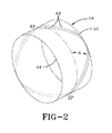
- the zigzag belt reinforcing structure 70 is comprises two layers of cord interwoven together formed as shown in Figure 2 .
- the zigzag belt structure is formed from a rubberized strip 43 of one or more cords, that is wound generally in the circumferential direction while being inclined to extend between alternating lateral edges 44 and 45 of a tire building drum 49 or core.
- the strip is wound along such zigzag path many times while the strip 43 is shifted a desired amount in the circumferential direction so as preferably not to form a gap between the adjoining strips 43.
- the strip 43 or ribbon has 1 to 20 cords in each ribbon.
- the cords extend in the circumferential direction while changing the bending direction at a turnaround point at both ends 44, 45.
- the cords of the zigzag belt structure cross with each other, typically at a cord angle A of 5 degrees to 30 degrees with respect to the equatorial plane EP of the tire when the strip 43 is reciprocated at least once between both side ends 44 and 45 of the ply within every 360 degrees of the circumference as mentioned above.
- the cord angle A may for instance be in a range of from 6 to 15 degrees or from 7 to 13 degrees.
- the two layers of cords formed in each zigzag belt structure are embedded and inseparable in the belt layer and there are preferably no cut ends at the outer lateral ends of the belt.
- the zigzag belt structure 70 is the most radially outward belt structure of the belt package 40. It is additionally preferred that there is only one zigzag belt structure.
- the zigzag belt structure 70 is preferably wider than the first belt structure, and more preferably is wider than both the first belt structure and the second belt structure 60.
- the ratio of the zigzag belt width Wz to the second belt structure 60 width Ws is preferably as follows: 0.6 ⁇ Ws / Wz ⁇ 1 or 0.7 ⁇ Ws / Wz ⁇ 0.9
- FIG. 4 illustrates a second embodiment of the present invention.
- the second embodiment is the same as the first embodiment, except for the following differences.
- the belt package further comprises an additional third belt layer 55 preferably located radially inward of the first belt layer 50.
- the third belt layer 55 preferably has a width less than the widths of all of the other belt layers 50, 60, 70. More preferably, the third belt layer 55 has a width in the range of 13% to 47% of the rim width between the flanges.
- Figure 5 illustrates a third embodiment of the present invention.
- the third embodiment is the same as the second embodiment as shown in Figure 4 , except for the following differences.
- the first belt layer 50 has been deleted.
- a second zigzag belt structure 90 has been added radially outward of the first zigzag belt structure 70.
- the second zigzag belt structure 90 has a width less than the first zigzag belt structure 70.
- the first zigzag belt structure 70 is the widest belt layer.
- the width of the belt layer 60 is less than the width of the first zigzag belt structure 70 and greater than the width of the second belt structure 90.
- the first and second zigzag belt structure are located adjacent each other and radially outward of the low angle belts 55, 60.
- the belt structure further includes a second zigzag belt structure 92 located radially outward of the first zigzag belt structure 70.
- the second zigzag belt structure 92 has a width less than the first zigzag belt structure 70.
- the zigzag belt structure 70 is the widest belt, and has a width greater than the width of the belt layer 60.
- Figure 7 illustrates an embodiment of a belt structure having two radially outer zigzag belt structures 70, 92 and three low angle belt layers 60, 50, 56, i.e. layers having cords arranged at an angle of 5 degrees or less with respect to the midcircumferential plane.
- the radially innermost zigzag belt structure 70 is the widest belt.
- the three low angle belt layers 60, 50, 56 are located radially inward of the zigzag belt structures 92, 70.
- the middle low angle belt layer 50 is preferably the narrowest belt layer of the belt package 40 and is located between to low angle belt layers 56, 60 having a greater width.
- FIG 8 illustrates yet another embodiment which is similar to the embodiment shown in Figure 6 , except for the following differences.
- the belt package 40 includes two radially outer zigzag belts 92, 70 and three low angle belts 55, 60, 61. Two of the low angle belts 60, 61 have the same width and are the widest low angle belts.
- the radially inward low angle belt 55 has the narrowest width in the range of 13% to 47 % of the rim width between the flanges.
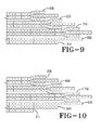
- Figure 9 illustrates still another embodiment of the present invention.
- Figure 9 is similar to the embodiment shown in Figure 3 , except for the following differences.
- the embodiment of Figure 9 includes two radially inner low angle belts 50, 60.
- the belt package further includes two additional zigzag belt structures 68, 69 wherein both belt structures are located radially outward of the first zigzag belt structure 70.
- the belt structures 68, 69, 70 have decreasing belt widths so that the radially innermost belt is the widest belt, and the radially outermost belt 68 is the narrowest.
- Figure 10 illustrates a variation of the embodiment of Figure 9 wherein a third low angle belt 51 is located radially inward of low angle belt 50 and has a width in the range of 13% to 47% of the rim width between the flanges.
- the cords are preferably continuously wound from one belt structure to the next.
- the cords of any of the above described carcass, spiral or zigzag belt layers described above may be nylon, nylon 6,6, aramid, or combinations thereof, including merged, hybrid, high energy constructions known to those skilled in the art.
- a suitable cord construction for the belt cords, carcass cords (or both) may comprise a composite of aramid and nylon, containing two cords of a polyamide (aramid) with construction of 3300 dtex with a 6.7 twist, and one nylon or nylon 6/6 cord having a construction of 1880 dtex, with a 4.5 twist.
- the overall merged cable twist is 6.7 for instance.
- the composite cords may have an elongation at break greater than 11 % and a tensile strength greater than 900 Newtons.
- the original linear density may be greater than 8500 dtex. Elongation, break, linear density and tensile strength are determined from cord samples taken after being dipped but prior to vulcanization of the tire.
Abstract
Description
- This invention relates to pneumatic tires having a carcass and a belt reinforcing structure, more particularly to high speed heavy load tires such as those used on aircraft or to heavy load tires such as truck tires, in particular radial truck tires.
- Pneumatic tires for high speed applications experience a high degree of flexure in the crown area of the tire as the tire enters and leaves the area of the footprint. This problem is particularly exacerbated on aircraft tires wherein the tires can reach speed of over 360 km/h at takeoff and landing.
- When a tire spins at very high speeds the crown area tends to grow in dimension due to the high angular accelerations and velocity, tending to pull the tread area radially outwardly. Counteracting these forces is the load of the vehicle which is only supported in the small area of the tire known as the footprint area.
- Current tire design drivers are an aircraft tire capable of high speed, high load and with reduced weight. It is known in the prior art to use zigzag belt layers in aircraft tires, such as disclosed in the
US-A- 5,427,167 . Zigzag belt layers have the advantage of eliminating cut belt edges at the outer lateral edge of the belt package. The inherent flexibility of the zigzag belt layers also help improve cornering forces. However, a tire designed with zigzag belt layers cannot carry as heavy a load as required by current commercial aircraft design requirements or commercial truck tire design requirements. Further, there is generally a tradeoff between load capacity and weight. Thus an improved tire is needed, which is capable of meeting high speed, high load and with reduced weight. - The invention relates to a tire in accordance with claim 1.
- Dependent claims refer to preferred embodiments of the invention.
- In one aspect of the invention, the tire is an aircraft tire. In another aspect of the invention, the tire is a truck tire such as a radial steer, drive or trailor tire.
- "Carcass" means the tire structure apart from the belt structure, tread, undertread, and sidewall rubber over the plies, but including the beads.
- "Circumferential" means lines or directions extending along the perimeter of the surface of the annular tread perpendicular to the axial direction.
- "Cord" means one of the reinforcement strands which the plies in the tire comprise.
- "Equatorial plane (EP)" or "midcircumferential plane" means the plane perpendicular to the tire's axis of rotation and passing through the center of its tread.
- "Ply" means a continuous layer of rubber-coated parallel cords.
- "Radial" and "radially" mean directions radially toward or away from the axis of rotation of the tire.
- "Radial-ply tire" means a belted or circumferentially-restricted pneumatic tire in which the ply cords which extend from bead to bead are laid at cord angles between 65° and 90° with respect to the equatorial plane of the tire.
-
-
FIG. 1 is a schematic cross-sectional view of a first embodiment of half of a tire according to the invention; -
FIG. 2 is a schematic perspective view of a zigzag belt layer in the middle of the formation; -
FIG. 3 is a schematically enlarged cross-sectional view of a first embodiment of half of a composite belt package for a tire showing the belt layer configuration; -
FIG. 4 is a schematically enlarged cross-sectional view of a second embodiment of a composite belt package showing the belt layer configuration; -
FIG. 5 is a schematically enlarged cross-sectional view of a third embodiment of a composite belt package showing the belt layer configuration; -
FIG. 6 is a schematically enlarged cross-sectional view of a fourth embodiment of a composite belt package showing the belt layer configuration; -
FIG. 7 is a schematically enlarged cross-sectional view of a fifth embodiment of a composite belt package showing the belt layer configuration; -
FIG. 8 is a schematically enlarged cross-sectional view of a sixth embodiment of a composite belt package showing the belt layer configuration; -
FIG. 9 is a schematically enlarged cross-sectional view of a seventh embodiment of a composite belt package showing the belt layer configuration; and -
FIG. 10 is a schematically enlarged cross-sectional view of an eighth embodiment of a composite belt package showing the belt layer configuration. -
Figure 1 illustrates a cross-sectional view of one half of aradial aircraft tire 10 of the present invention. The tire is preferably symmetrical about the midcircumferential plane so that only one half is illustrated. As shown, the aircraft tire comprises a pair ofbead portions 12 each containing abead core 14 embedded therein. One example of a bead core suitable for use in an aircraft tire is shown inUS-A- 6,571,847 . Thebead core 14 preferably has an aluminum, aluminum alloy or other light weight alloy in thecenter portion 13 surrounded by a plurality of steel sheath wires 15. A person skilled in the art may appreciate that other bead cores may also be utilized. - The aircraft tire further comprises a
sidewall portion 16 extending substantially outward from each of thebead portions 12 in the radial direction of the tire, and atread portion 20 extending between the radially outer ends of thesidewall portions 16. Furthermore, thetire 10 is reinforced with a carcass 22 toroidally extending from one of thebead portions 12 to theother bead portion 12. The carcass 22 comprisesinner carcass plies 24 andouter carcass plies 26, preferably oriented in the radial direction. Among these carcass plies, typically fourinner plies 24 are wound around thebead core 14 from inside of the tire toward outside thereof to form turnup portions, while typically twoouter plies 26 are extended downward to thebead core 14 along the outside of the turnup portion of theinner carcass ply 24. Each of these carcass plies 24, 26 may comprise any suitable cord, typically nylon cords such as nylon-6,6 cords extending substantially perpendicular to an equatorial plane EP of the tire (i.e., extending in the radial direction of the tire). Preferably the nylon cords have an 1890 denier/2/2 or 1890 denier/3 construction. One or more of thecarcass plies US-A- 4,893,665 ,US-A- 4,155,394 orUS-A- 6,799,618 . - The
aircraft tire 10 further comprises abelt package 40 arranged between the carcass 22 and thetread rubber 20.Figure 3 illustrates a first embodiment of one half of abelt package 40 suitable for use in the aircraft tire. Thebelt package 40 is preferably symmetrical about the mid-circumferential plane so that only one half of the belt package is illustrated. Thebelt package 40 as shown comprises afirst belt layer 50 located adjacent the carcass. Thefirst belt layer 50 is preferably formed of cords having an angle of 5 degrees or less, more preferably 0.2 to 1.5 degrees, with respect to the mid-circumferential plane. Preferably, thefirst belt layer 50 is formed of arubberized strip 43 of two or more cords made by spirally or helically winding the cords at an angle of plus or minus 5 degrees or less relative to the circumferential direction. Thefirst belt layer 50 is preferably the narrowest belt structure of thebelt package 40, and has a width in the range of 13% to 100% of the rim width (width between flanges), and more particularly in the range of 20% to 70% of the rim width (width between flanges), and most particularly in the range of 30% to 42% of the rim width (width between flanges). - The
belt package 40 further comprises asecond belt layer 60 located radially outward of thefirst belt layer 50. Thesecond belt layer 60 is preferably formed of cords having an angle of 5 degrees or less, more preferably 0.2 to 1.5 degrees, with respect to the mid-circumferential plane. Preferably, thesecond belt layer 60 is formed of arubberized strip 43 of two or more cords made by spirally or helically winding the cords at an angle of plus or minus 5 degrees or less relative to the circumferential direction. The second belt layer has a width in the range of 101 % to 120% of the rim width or from 105% to 115% of the rim width, and preferably has a width greater than thefirst belt layer 50. - The
belt package 40 further comprises at least one zigzagbelt reinforcing structure 70. The zigzagbelt reinforcing structure 70 is comprises two layers of cord interwoven together formed as shown inFigure 2 . The zigzag belt structure is formed from arubberized strip 43 of one or more cords, that is wound generally in the circumferential direction while being inclined to extend between alternatinglateral edges tire building drum 49 or core. The strip is wound along such zigzag path many times while thestrip 43 is shifted a desired amount in the circumferential direction so as preferably not to form a gap between the adjoining strips 43. Preferably, thestrip 43 or ribbon has 1 to 20 cords in each ribbon. As a result, the cords extend in the circumferential direction while changing the bending direction at a turnaround point at both ends 44, 45. The cords of the zigzag belt structure cross with each other, typically at a cord angle A of 5 degrees to 30 degrees with respect to the equatorial plane EP of the tire when thestrip 43 is reciprocated at least once between both side ends 44 and 45 of the ply within every 360 degrees of the circumference as mentioned above. The cord angle A may for instance be in a range of from 6 to 15 degrees or from 7 to 13 degrees. The two layers of cords formed in each zigzag belt structure are embedded and inseparable in the belt layer and there are preferably no cut ends at the outer lateral ends of the belt. - It is preferred that the
zigzag belt structure 70 is the most radially outward belt structure of thebelt package 40. It is additionally preferred that there is only one zigzag belt structure. Thezigzag belt structure 70 is preferably wider than the first belt structure, and more preferably is wider than both the first belt structure and thesecond belt structure 60. The ratio of the zigzag belt width Wz to thesecond belt structure 60 width Ws is preferably as follows:
-
Figure 4 illustrates a second embodiment of the present invention. The second embodiment is the same as the first embodiment, except for the following differences. The belt package further comprises an additionalthird belt layer 55 preferably located radially inward of thefirst belt layer 50. Thethird belt layer 55 preferably has a width less than the widths of all of the other belt layers 50, 60, 70. More preferably, thethird belt layer 55 has a width in the range of 13% to 47% of the rim width between the flanges. -
Figure 5 illustrates a third embodiment of the present invention. The third embodiment is the same as the second embodiment as shown inFigure 4 , except for the following differences. Thefirst belt layer 50 has been deleted. A secondzigzag belt structure 90 has been added radially outward of the firstzigzag belt structure 70. The secondzigzag belt structure 90 has a width less than the firstzigzag belt structure 70. The firstzigzag belt structure 70 is the widest belt layer. The width of thebelt layer 60 is less than the width of the firstzigzag belt structure 70 and greater than the width of thesecond belt structure 90. Preferably, the first and second zigzag belt structure are located adjacent each other and radially outward of thelow angle belts -
Figure 6 illustrates an additional embodiment similar toFigure 4 , except for the following differences. The belt structure further includes a secondzigzag belt structure 92 located radially outward of the firstzigzag belt structure 70. The secondzigzag belt structure 92 has a width less than the firstzigzag belt structure 70. Thezigzag belt structure 70 is the widest belt, and has a width greater than the width of thebelt layer 60. -
Figure 7 illustrates an embodiment of a belt structure having two radially outerzigzag belt structures zigzag belt structure 70 is the widest belt. The three low angle belt layers 60, 50, 56 are located radially inward of thezigzag belt structures angle belt layer 50 is preferably the narrowest belt layer of thebelt package 40 and is located between to low angle belt layers 56, 60 having a greater width. -
Figure 8 illustrates yet another embodiment which is similar to the embodiment shown inFigure 6 , except for the following differences. Thebelt package 40 includes two radially outerzigzag belts low angle belts low angle belts low angle belt 55 has the narrowest width in the range of 13% to 47 % of the rim width between the flanges. -
Figure 9 illustrates still another embodiment of the present invention.Figure 9 is similar to the embodiment shown inFigure 3 , except for the following differences. The embodiment ofFigure 9 includes two radially innerlow angle belts zigzag belt structures zigzag belt structure 70. Thebelt structures outermost belt 68 is the narrowest.Figure 10 illustrates a variation of the embodiment ofFigure 9 wherein a thirdlow angle belt 51 is located radially inward oflow angle belt 50 and has a width in the range of 13% to 47% of the rim width between the flanges. - In any of the above described embodiments, the cords are preferably continuously wound from one belt structure to the next.
- The cords of any of the above described carcass, spiral or zigzag belt layers described above may be nylon, nylon 6,6, aramid, or combinations thereof, including merged, hybrid, high energy constructions known to those skilled in the art. One example of a suitable cord construction for the belt cords, carcass cords (or both), may comprise a composite of aramid and nylon, containing two cords of a polyamide (aramid) with construction of 3300 dtex with a 6.7 twist, and one nylon or nylon 6/6 cord having a construction of 1880 dtex, with a 4.5 twist. The overall merged cable twist is 6.7 for instance. The composite cords may have an elongation at break greater than 11 % and a tensile strength greater than 900 Newtons. Optionally, the original linear density may be greater than 8500 dtex. Elongation, break, linear density and tensile strength are determined from cord samples taken after being dipped but prior to vulcanization of the tire.
Claims (15)
- A pneumatic tire having a carcass (22) and a belt reinforcing structure (40), the belt reinforcing structure (40) comprising a first and a second belt layer (50, 60), one or both of the first and a second belt layer (50, 60) having cords arranged at an angle of 5 degrees or less with respect to the midcircumferential plane of the tire (10), and a zigzag belt reinforcing structure (70) comprising cords inclined at an angle in a range of from 5 to 30 degrees relative to the midcircumferential of the tire extending in alternation to turnaround points at lateral edges (44, 45) of the zigzag belt reinforcing structure (70), wherein the axial width of the zigzag belt reinforcing structure (70) is wider than the axial width of the first and second belt layer (50, 60).
- The tire of claim 1 wherein the zigzag belt reinforcing structure (70) forms two layers of cords.
- The pneumatic tire of claim 1 or 2 wherein the zigzag belt reinforcing structure (70) is located radially outward of the first and second belt layer (50, 60).
- The pneumatic tire of at least one of the previous claims wherein the first and second belt layers (50, 60) are formed from helically winding the cords forming two spiral layers.
- The pneumatic tire of at least one of the previous claims wherein the ratio of the axial width (Wz) of the zigzag belt reinforcing structure (70) to the axial width (Ws) of the widest of the first and second belt layers (50, 60) is in the range of: 0.6 < Ws/Wz < 1.
- The pneumatic tire of at least one of the previous claims wherein one or more of the first and second belt (50, 60) and the zigzag belt reinforcing structure (70) comprise cords made of a nylon and aramid blend or cords made of aramid.
- The pneumatic tire of at least one of the previous claims further comprising a third belt layer (55) located radially inward of the first and second belt layers (50, 60), wherein the third belt layer (55) preferably has an axial width less than the axial width of the first and second belt layer (50, 60).
- The pneumatic tire of at least one of the previous claims wherein the belt structure (40) comprises one or two radially inner spiral belt layers, two zigzag belt reinforcing structures (70), and one or two radially outer spiral belt layers, and wherein at least one or both of the zigzag belt reinforcing structures (70) is wider than the axial width of at least two or all of the spiral belt layers.
- The pneumatic tire of at least one of the previous claims wherein at least one belt layer has cords having a percent elongation at break greater than 11 %, and a break strength greater than 900 N with an original linear density of greater than 8500 dtex.
- The pneumatic tire of at least one of the previous claims comprising a first belt layer having cords arranged at an angle of 5 degrees or less with respect to the midcircumferential plane, a second belt layer located radially inward of the first belt layer and having an axial width less than the first belt layer, and a third belt layer located radially inward of the second belt layer and having an axial width greater than the second or the first belt layer, and a zigzag belt reinforcing structure (70) comprising cords inclined at an angle in a range of from 5 to 30 degrees relative to the midcircumferential of the tire extending in alternation to turnaround points at lateral edges (44, 45) of the zigzag belt reinforcing structure (70), wherein the zigzag belt reinforcing structure (70) is the widest belt.
- The pneumatic tire of at least one of the previous claims comprising a first belt layer having cords arranged at an angle of 5 degrees or less with respect to the midcircumferential plane, a second belt layer located radially outward of the first belt layer and having an axial width less than the first belt layer, and a third belt layer located radially inward of the second belt layer and having an axial width greater than the second belt layer or the first belt layer, and a zigzag belt reinforcing structure (70) comprising cords inclined at an angle in a range of from 5 to 30 degrees relative to the midcircumferential of the tire extending in alternation to turnaround points at lateral edges (44, 45) of the zigzag belt reinforcing structure (70), wherein the zigzag belt reinforcing structure (70) is the widest belt.
- The pneumatic tire of claim 10 or 11 further comprising a second zigzag belt reinforcing structure located radially outward of the first zigzag belt reinforcing structure and having a width less than the first zigzag belt structure.
- The pneumatic tire of claim 10 or 11 further comprising a second zigzag belt reinforcing structure located radially outward of the first zigzag belt reinforcing structure and having a width larger than the first zigzag belt structure.
- The pneumatic tire of at least one of the previous claims wherein the carcass is a radial carcass and/or the carcass ply cord fiber is nylon.
- The pneumatic tire of at least one of the previous claims wherein the first belt layer is located radially inward of the second belt layer and/or wherein the second belt layer is wider than the first belt layer.
Applications Claiming Priority (1)
| Application Number | Priority Date | Filing Date | Title |
|---|---|---|---|
| US12/860,119 US8578988B2 (en) | 2010-08-20 | 2010-08-20 | Reduced weight aircraft tire |
Publications (3)
| Publication Number | Publication Date |
|---|---|
| EP2420396A2 true EP2420396A2 (en) | 2012-02-22 |
| EP2420396A3 EP2420396A3 (en) | 2012-04-25 |
| EP2420396B1 EP2420396B1 (en) | 2013-12-25 |
Family
ID=44677492
Family Applications (1)
| Application Number | Title | Priority Date | Filing Date |
|---|---|---|---|
| EP11177423.8A Active EP2420396B1 (en) | 2010-08-20 | 2011-08-12 | Pneumatic tire |
Country Status (3)
| Country | Link |
|---|---|
| US (1) | US8578988B2 (en) |
| EP (1) | EP2420396B1 (en) |
| JP (1) | JP5893866B2 (en) |
Cited By (6)
| Publication number | Priority date | Publication date | Assignee | Title |
|---|---|---|---|---|
| GB2492868A (en) * | 2011-06-13 | 2013-01-16 | Goodyear Tire & Rubber | Pneumatic tyre |
| GB2507198A (en) * | 2011-06-13 | 2014-04-23 | Goodyear Tire & Rubber | Pneumatic tyre |
| GB2495167B (en) * | 2011-06-13 | 2014-10-01 | Goodyear Tire & Rubber | Pneumatic tyre |
| WO2015071152A1 (en) * | 2013-11-15 | 2015-05-21 | Compagnie Generale Des Etablissements Michelin | Crown reinforcement for an aircraft tyre |
| US9272577B2 (en) | 2011-06-13 | 2016-03-01 | The Goodyear Tire & Rubber Company | Aircraft radial tire |
| EP3131762B1 (en) * | 2014-04-18 | 2019-06-12 | Compagnie Générale des Etablissements Michelin | Crown reinforcement for an airplane tyre |
Families Citing this family (3)
| Publication number | Priority date | Publication date | Assignee | Title |
|---|---|---|---|---|
| US9199512B2 (en) * | 2012-12-20 | 2015-12-01 | The Goodyear Tire & Rubber Company | Pneumatic tire with geodesic belt |
| FR3012077B1 (en) * | 2013-10-23 | 2016-12-09 | Michelin & Cie | PNEUMATIC SUMMIT FRAME FOR AIRCRAFT |
| FR3020015B1 (en) * | 2014-04-18 | 2016-05-06 | Michelin & Cie | PNEUMATIC SUMMIT FRAME FOR AIRCRAFT |
Citations (5)
| Publication number | Priority date | Publication date | Assignee | Title |
|---|---|---|---|---|
| US4155394A (en) | 1977-08-29 | 1979-05-22 | The Goodyear Tire & Rubber Company | Tire cord composite and pneumatic tire |
| US4893665A (en) | 1988-02-17 | 1990-01-16 | The Goodyear Tire & Rubber Company | Cables for reinforcing deformable articles and articles reinforced by said cables |
| US5427167A (en) | 1991-10-29 | 1995-06-27 | Bridgestone Corporation | Pneumatic radial tires for airplanes including zig-zag belt cords |
| US6571847B1 (en) | 2002-01-24 | 2003-06-03 | The Goodyear Tire & Rubber Company | Light weight alloy bead core |
| US6799618B2 (en) | 2002-12-18 | 2004-10-05 | The Goodyear Tire & Rubber Company | Pneumatic tire having an overlay reinforcement |
Family Cites Families (5)
| Publication number | Priority date | Publication date | Assignee | Title |
|---|---|---|---|---|
| JP4544782B2 (en) * | 2001-06-05 | 2010-09-15 | 株式会社ブリヂストン | Radial tire |
| US7712499B2 (en) * | 2002-01-24 | 2010-05-11 | Bridgestone Corporation | Pneumatic radial tire with specified belt layer |
| US20040163748A1 (en) * | 2003-02-24 | 2004-08-26 | Kiyoshi Ueyoko | Tire having a composite belt structure |
| US7360571B2 (en) * | 2003-09-16 | 2008-04-22 | The Goodyear Tire & Rubber Company | Pneumatic tire with composite belt structure |
| JP2009196548A (en) * | 2008-02-22 | 2009-09-03 | Bridgestone Corp | Pneumatic tire |
-
2010
- 2010-08-20 US US12/860,119 patent/US8578988B2/en active Active
-
2011
- 2011-08-08 JP JP2011172588A patent/JP5893866B2/en active Active
- 2011-08-12 EP EP11177423.8A patent/EP2420396B1/en active Active
Patent Citations (5)
| Publication number | Priority date | Publication date | Assignee | Title |
|---|---|---|---|---|
| US4155394A (en) | 1977-08-29 | 1979-05-22 | The Goodyear Tire & Rubber Company | Tire cord composite and pneumatic tire |
| US4893665A (en) | 1988-02-17 | 1990-01-16 | The Goodyear Tire & Rubber Company | Cables for reinforcing deformable articles and articles reinforced by said cables |
| US5427167A (en) | 1991-10-29 | 1995-06-27 | Bridgestone Corporation | Pneumatic radial tires for airplanes including zig-zag belt cords |
| US6571847B1 (en) | 2002-01-24 | 2003-06-03 | The Goodyear Tire & Rubber Company | Light weight alloy bead core |
| US6799618B2 (en) | 2002-12-18 | 2004-10-05 | The Goodyear Tire & Rubber Company | Pneumatic tire having an overlay reinforcement |
Cited By (11)
| Publication number | Priority date | Publication date | Assignee | Title |
|---|---|---|---|---|
| GB2492868A (en) * | 2011-06-13 | 2013-01-16 | Goodyear Tire & Rubber | Pneumatic tyre |
| GB2492868B (en) * | 2011-06-13 | 2013-10-02 | Goodyear Tire & Rubber | Pneumatic tyre |
| GB2507198A (en) * | 2011-06-13 | 2014-04-23 | Goodyear Tire & Rubber | Pneumatic tyre |
| GB2507198B (en) * | 2011-06-13 | 2014-09-10 | Goodyear Tire & Rubber | Pneumatic tyre |
| GB2495167B (en) * | 2011-06-13 | 2014-10-01 | Goodyear Tire & Rubber | Pneumatic tyre |
| US9272577B2 (en) | 2011-06-13 | 2016-03-01 | The Goodyear Tire & Rubber Company | Aircraft radial tire |
| WO2015071152A1 (en) * | 2013-11-15 | 2015-05-21 | Compagnie Generale Des Etablissements Michelin | Crown reinforcement for an aircraft tyre |
| FR3013259A1 (en) * | 2013-11-15 | 2015-05-22 | Michelin & Cie | TOP REINFORCEMENT FOR AIR TIRE |
| CN105705343A (en) * | 2013-11-15 | 2016-06-22 | 米其林集团总公司 | Crown reinforcement for an aircraft tyre |
| US10589573B2 (en) | 2013-11-15 | 2020-03-17 | Compagnie Generale Des Etablissements Michelin | Crown reinforcement for an aircraft tire |
| EP3131762B1 (en) * | 2014-04-18 | 2019-06-12 | Compagnie Générale des Etablissements Michelin | Crown reinforcement for an airplane tyre |
Also Published As
| Publication number | Publication date |
|---|---|
| EP2420396A3 (en) | 2012-04-25 |
| JP2012041040A (en) | 2012-03-01 |
| US8578988B2 (en) | 2013-11-12 |
| JP5893866B2 (en) | 2016-03-23 |
| US20120043000A1 (en) | 2012-02-23 |
| EP2420396B1 (en) | 2013-12-25 |
Similar Documents
| Publication | Publication Date | Title |
|---|---|---|
| EP2394822B1 (en) | Tire comprising a zigzag belt reinforcing structure, in particular a reduced weight aircraft tire | |
| EP2420396B1 (en) | Pneumatic tire | |
| US20080105352A1 (en) | Reduced weight aircraft tire | |
| US11186122B2 (en) | Reduced weight aircraft tire | |
| US20240051344A1 (en) | Reduced weight aircraft tire | |
| US20160200147A1 (en) | Reduced weight aircraft tire | |
| EP1449680A1 (en) | A tire having a composite belt structure | |
| EP2977229B1 (en) | Reduced weight aircraft tire | |
| US8967213B2 (en) | Aircraft tire | |
| EP3825149A1 (en) | Reduced weight aircraft tire | |
| EP3290232B1 (en) | Tire with low weight and high burst strength | |
| EP2444259B1 (en) | Reduced weight tire | |
| EP2444258A2 (en) | Reduced weight tire | |
| US20120312440A1 (en) | Reduced weight aircraft tire | |
| US20210380229A1 (en) | Reduced weight aircraft tire | |
| US20210146727A1 (en) | Reduced weight aircraft tire | |
| GB2507199A (en) | Pneumatic tyre |
Legal Events
| Date | Code | Title | Description |
|---|---|---|---|
| AK | Designated contracting states |
Kind code of ref document: A2 Designated state(s): AL AT BE BG CH CY CZ DE DK EE ES FI FR GB GR HR HU IE IS IT LI LT LU LV MC MK MT NL NO PL PT RO RS SE SI SK SM TR |
|
| AX | Request for extension of the european patent |
Extension state: BA ME |
|
| PUAI | Public reference made under article 153(3) epc to a published international application that has entered the european phase |
Free format text: ORIGINAL CODE: 0009012 |
|
| PUAL | Search report despatched |
Free format text: ORIGINAL CODE: 0009013 |
|
| AK | Designated contracting states |
Kind code of ref document: A3 Designated state(s): AL AT BE BG CH CY CZ DE DK EE ES FI FR GB GR HR HU IE IS IT LI LT LU LV MC MK MT NL NO PL PT RO RS SE SI SK SM TR |
|
| AX | Request for extension of the european patent |
Extension state: BA ME |
|
| RIC1 | Information provided on ipc code assigned before grant |
Ipc: B60C 19/00 20060101ALI20120322BHEP Ipc: B60C 9/22 20060101ALI20120322BHEP Ipc: B60C 9/20 20060101AFI20120322BHEP Ipc: B60C 9/26 20060101ALI20120322BHEP |
|
| 17P | Request for examination filed |
Effective date: 20121025 |
|
| 17Q | First examination report despatched |
Effective date: 20130204 |
|
| GRAP | Despatch of communication of intention to grant a patent |
Free format text: ORIGINAL CODE: EPIDOSNIGR1 |
|
| INTG | Intention to grant announced |
Effective date: 20130715 |
|
| GRAS | Grant fee paid |
Free format text: ORIGINAL CODE: EPIDOSNIGR3 |
|
| GRAA | (expected) grant |
Free format text: ORIGINAL CODE: 0009210 |
|
| AK | Designated contracting states |
Kind code of ref document: B1 Designated state(s): AL AT BE BG CH CY CZ DE DK EE ES FI FR GB GR HR HU IE IS IT LI LT LU LV MC MK MT NL NO PL PT RO RS SE SI SK SM TR |
|
| REG | Reference to a national code |
Ref country code: GB Ref legal event code: FG4D |
|
| REG | Reference to a national code |
Ref country code: CH Ref legal event code: EP |
|
| REG | Reference to a national code |
Ref country code: AT Ref legal event code: REF Ref document number: 646406 Country of ref document: AT Kind code of ref document: T Effective date: 20140115 |
|
| REG | Reference to a national code |
Ref country code: IE Ref legal event code: FG4D |
|
| REG | Reference to a national code |
Ref country code: DE Ref legal event code: R096 Ref document number: 602011004321 Country of ref document: DE Effective date: 20140220 |
|
| PG25 | Lapsed in a contracting state [announced via postgrant information from national office to epo] |
Ref country code: NO Free format text: LAPSE BECAUSE OF FAILURE TO SUBMIT A TRANSLATION OF THE DESCRIPTION OR TO PAY THE FEE WITHIN THE PRESCRIBED TIME-LIMIT Effective date: 20140325 Ref country code: HR Free format text: LAPSE BECAUSE OF FAILURE TO SUBMIT A TRANSLATION OF THE DESCRIPTION OR TO PAY THE FEE WITHIN THE PRESCRIBED TIME-LIMIT Effective date: 20131225 Ref country code: FI Free format text: LAPSE BECAUSE OF FAILURE TO SUBMIT A TRANSLATION OF THE DESCRIPTION OR TO PAY THE FEE WITHIN THE PRESCRIBED TIME-LIMIT Effective date: 20131225 Ref country code: LT Free format text: LAPSE BECAUSE OF FAILURE TO SUBMIT A TRANSLATION OF THE DESCRIPTION OR TO PAY THE FEE WITHIN THE PRESCRIBED TIME-LIMIT Effective date: 20131225 Ref country code: SE Free format text: LAPSE BECAUSE OF FAILURE TO SUBMIT A TRANSLATION OF THE DESCRIPTION OR TO PAY THE FEE WITHIN THE PRESCRIBED TIME-LIMIT Effective date: 20131225 |
|
| REG | Reference to a national code |
Ref country code: NL Ref legal event code: VDEP Effective date: 20131225 |
|
| REG | Reference to a national code |
Ref country code: AT Ref legal event code: MK05 Ref document number: 646406 Country of ref document: AT Kind code of ref document: T Effective date: 20131225 |
|
| REG | Reference to a national code |
Ref country code: LT Ref legal event code: MG4D |
|
| PG25 | Lapsed in a contracting state [announced via postgrant information from national office to epo] |
Ref country code: LV Free format text: LAPSE BECAUSE OF FAILURE TO SUBMIT A TRANSLATION OF THE DESCRIPTION OR TO PAY THE FEE WITHIN THE PRESCRIBED TIME-LIMIT Effective date: 20131225 Ref country code: RS Free format text: LAPSE BECAUSE OF FAILURE TO SUBMIT A TRANSLATION OF THE DESCRIPTION OR TO PAY THE FEE WITHIN THE PRESCRIBED TIME-LIMIT Effective date: 20131225 |
|
| PG25 | Lapsed in a contracting state [announced via postgrant information from national office to epo] |
Ref country code: EE Free format text: LAPSE BECAUSE OF FAILURE TO SUBMIT A TRANSLATION OF THE DESCRIPTION OR TO PAY THE FEE WITHIN THE PRESCRIBED TIME-LIMIT Effective date: 20131225 Ref country code: BE Free format text: LAPSE BECAUSE OF FAILURE TO SUBMIT A TRANSLATION OF THE DESCRIPTION OR TO PAY THE FEE WITHIN THE PRESCRIBED TIME-LIMIT Effective date: 20131225 Ref country code: IS Free format text: LAPSE BECAUSE OF FAILURE TO SUBMIT A TRANSLATION OF THE DESCRIPTION OR TO PAY THE FEE WITHIN THE PRESCRIBED TIME-LIMIT Effective date: 20140425 |
|
| PG25 | Lapsed in a contracting state [announced via postgrant information from national office to epo] |
Ref country code: CZ Free format text: LAPSE BECAUSE OF FAILURE TO SUBMIT A TRANSLATION OF THE DESCRIPTION OR TO PAY THE FEE WITHIN THE PRESCRIBED TIME-LIMIT Effective date: 20131225 Ref country code: CY Free format text: LAPSE BECAUSE OF FAILURE TO SUBMIT A TRANSLATION OF THE DESCRIPTION OR TO PAY THE FEE WITHIN THE PRESCRIBED TIME-LIMIT Effective date: 20131225 Ref country code: AT Free format text: LAPSE BECAUSE OF FAILURE TO SUBMIT A TRANSLATION OF THE DESCRIPTION OR TO PAY THE FEE WITHIN THE PRESCRIBED TIME-LIMIT Effective date: 20131225 Ref country code: NL Free format text: LAPSE BECAUSE OF FAILURE TO SUBMIT A TRANSLATION OF THE DESCRIPTION OR TO PAY THE FEE WITHIN THE PRESCRIBED TIME-LIMIT Effective date: 20131225 Ref country code: ES Free format text: LAPSE BECAUSE OF FAILURE TO SUBMIT A TRANSLATION OF THE DESCRIPTION OR TO PAY THE FEE WITHIN THE PRESCRIBED TIME-LIMIT Effective date: 20131225 Ref country code: SK Free format text: LAPSE BECAUSE OF FAILURE TO SUBMIT A TRANSLATION OF THE DESCRIPTION OR TO PAY THE FEE WITHIN THE PRESCRIBED TIME-LIMIT Effective date: 20131225 Ref country code: PT Free format text: LAPSE BECAUSE OF FAILURE TO SUBMIT A TRANSLATION OF THE DESCRIPTION OR TO PAY THE FEE WITHIN THE PRESCRIBED TIME-LIMIT Effective date: 20140428 Ref country code: RO Free format text: LAPSE BECAUSE OF FAILURE TO SUBMIT A TRANSLATION OF THE DESCRIPTION OR TO PAY THE FEE WITHIN THE PRESCRIBED TIME-LIMIT Effective date: 20131225 |
|
| REG | Reference to a national code |
Ref country code: DE Ref legal event code: R097 Ref document number: 602011004321 Country of ref document: DE |
|
| PG25 | Lapsed in a contracting state [announced via postgrant information from national office to epo] |
Ref country code: DK Free format text: LAPSE BECAUSE OF FAILURE TO SUBMIT A TRANSLATION OF THE DESCRIPTION OR TO PAY THE FEE WITHIN THE PRESCRIBED TIME-LIMIT Effective date: 20131225 |
|
| PLBE | No opposition filed within time limit |
Free format text: ORIGINAL CODE: 0009261 |
|
| STAA | Information on the status of an ep patent application or granted ep patent |
Free format text: STATUS: NO OPPOSITION FILED WITHIN TIME LIMIT |
|
| PG25 | Lapsed in a contracting state [announced via postgrant information from national office to epo] |
Ref country code: PL Free format text: LAPSE BECAUSE OF FAILURE TO SUBMIT A TRANSLATION OF THE DESCRIPTION OR TO PAY THE FEE WITHIN THE PRESCRIBED TIME-LIMIT Effective date: 20131225 |
|
| 26N | No opposition filed |
Effective date: 20140926 |
|
| REG | Reference to a national code |
Ref country code: DE Ref legal event code: R097 Ref document number: 602011004321 Country of ref document: DE Effective date: 20140926 |
|
| PG25 | Lapsed in a contracting state [announced via postgrant information from national office to epo] |
Ref country code: MC Free format text: LAPSE BECAUSE OF FAILURE TO SUBMIT A TRANSLATION OF THE DESCRIPTION OR TO PAY THE FEE WITHIN THE PRESCRIBED TIME-LIMIT Effective date: 20131225 Ref country code: LU Free format text: LAPSE BECAUSE OF FAILURE TO SUBMIT A TRANSLATION OF THE DESCRIPTION OR TO PAY THE FEE WITHIN THE PRESCRIBED TIME-LIMIT Effective date: 20140812 |
|
| REG | Reference to a national code |
Ref country code: CH Ref legal event code: PL |
|
| PG25 | Lapsed in a contracting state [announced via postgrant information from national office to epo] |
Ref country code: CH Free format text: LAPSE BECAUSE OF NON-PAYMENT OF DUE FEES Effective date: 20140831 Ref country code: LI Free format text: LAPSE BECAUSE OF NON-PAYMENT OF DUE FEES Effective date: 20140831 |
|
| REG | Reference to a national code |
Ref country code: IE Ref legal event code: MM4A |
|
| PG25 | Lapsed in a contracting state [announced via postgrant information from national office to epo] |
Ref country code: SI Free format text: LAPSE BECAUSE OF FAILURE TO SUBMIT A TRANSLATION OF THE DESCRIPTION OR TO PAY THE FEE WITHIN THE PRESCRIBED TIME-LIMIT Effective date: 20131225 |
|
| PG25 | Lapsed in a contracting state [announced via postgrant information from national office to epo] |
Ref country code: IE Free format text: LAPSE BECAUSE OF NON-PAYMENT OF DUE FEES Effective date: 20140812 |
|
| PG25 | Lapsed in a contracting state [announced via postgrant information from national office to epo] |
Ref country code: SM Free format text: LAPSE BECAUSE OF FAILURE TO SUBMIT A TRANSLATION OF THE DESCRIPTION OR TO PAY THE FEE WITHIN THE PRESCRIBED TIME-LIMIT Effective date: 20131225 |
|
| PG25 | Lapsed in a contracting state [announced via postgrant information from national office to epo] |
Ref country code: BG Free format text: LAPSE BECAUSE OF FAILURE TO SUBMIT A TRANSLATION OF THE DESCRIPTION OR TO PAY THE FEE WITHIN THE PRESCRIBED TIME-LIMIT Effective date: 20131225 Ref country code: MT Free format text: LAPSE BECAUSE OF FAILURE TO SUBMIT A TRANSLATION OF THE DESCRIPTION OR TO PAY THE FEE WITHIN THE PRESCRIBED TIME-LIMIT Effective date: 20131225 Ref country code: GR Free format text: LAPSE BECAUSE OF FAILURE TO SUBMIT A TRANSLATION OF THE DESCRIPTION OR TO PAY THE FEE WITHIN THE PRESCRIBED TIME-LIMIT Effective date: 20140326 |
|
| REG | Reference to a national code |
Ref country code: FR Ref legal event code: PLFP Year of fee payment: 6 |
|
| PG25 | Lapsed in a contracting state [announced via postgrant information from national office to epo] |
Ref country code: HU Free format text: LAPSE BECAUSE OF FAILURE TO SUBMIT A TRANSLATION OF THE DESCRIPTION OR TO PAY THE FEE WITHIN THE PRESCRIBED TIME-LIMIT; INVALID AB INITIO Effective date: 20110812 Ref country code: TR Free format text: LAPSE BECAUSE OF FAILURE TO SUBMIT A TRANSLATION OF THE DESCRIPTION OR TO PAY THE FEE WITHIN THE PRESCRIBED TIME-LIMIT Effective date: 20131225 |
|
| REG | Reference to a national code |
Ref country code: FR Ref legal event code: PLFP Year of fee payment: 7 |
|
| PGFP | Annual fee paid to national office [announced via postgrant information from national office to epo] |
Ref country code: IT Payment date: 20170816 Year of fee payment: 7 |
|
| PG25 | Lapsed in a contracting state [announced via postgrant information from national office to epo] |
Ref country code: MK Free format text: LAPSE BECAUSE OF FAILURE TO SUBMIT A TRANSLATION OF THE DESCRIPTION OR TO PAY THE FEE WITHIN THE PRESCRIBED TIME-LIMIT Effective date: 20131225 |
|
| REG | Reference to a national code |
Ref country code: FR Ref legal event code: PLFP Year of fee payment: 8 |
|
| PG25 | Lapsed in a contracting state [announced via postgrant information from national office to epo] |
Ref country code: AL Free format text: LAPSE BECAUSE OF FAILURE TO SUBMIT A TRANSLATION OF THE DESCRIPTION OR TO PAY THE FEE WITHIN THE PRESCRIBED TIME-LIMIT Effective date: 20131225 |
|
| PG25 | Lapsed in a contracting state [announced via postgrant information from national office to epo] |
Ref country code: IT Free format text: LAPSE BECAUSE OF NON-PAYMENT OF DUE FEES Effective date: 20180812 |
|
| PGFP | Annual fee paid to national office [announced via postgrant information from national office to epo] |
Ref country code: FR Payment date: 20230620 Year of fee payment: 13 |
|
| PGFP | Annual fee paid to national office [announced via postgrant information from national office to epo] |
Ref country code: GB Payment date: 20230622 Year of fee payment: 13 |
|
| PGFP | Annual fee paid to national office [announced via postgrant information from national office to epo] |
Ref country code: DE Payment date: 20230620 Year of fee payment: 13 |