EP2376302B1 - Hinge assembly for vehicle interior trim component - Google Patents
Hinge assembly for vehicle interior trim component Download PDFInfo
- Publication number
- EP2376302B1 EP2376302B1 EP10700095.2A EP10700095A EP2376302B1 EP 2376302 B1 EP2376302 B1 EP 2376302B1 EP 10700095 A EP10700095 A EP 10700095A EP 2376302 B1 EP2376302 B1 EP 2376302B1
- Authority
- EP
- European Patent Office
- Prior art keywords
- cam
- follower
- axle
- cover
- hinge assembly
- Prior art date
- Legal status (The legal status is an assumption and is not a legal conclusion. Google has not performed a legal analysis and makes no representation as to the accuracy of the status listed.)
- Not-in-force
Links
Images


Classifications
-
- B—PERFORMING OPERATIONS; TRANSPORTING
- B60—VEHICLES IN GENERAL
- B60J—WINDOWS, WINDSCREENS, NON-FIXED ROOFS, DOORS, OR SIMILAR DEVICES FOR VEHICLES; REMOVABLE EXTERNAL PROTECTIVE COVERINGS SPECIALLY ADAPTED FOR VEHICLES
- B60J3/00—Antiglare equipment associated with windows or windscreens; Sun visors for vehicles
- B60J3/02—Antiglare equipment associated with windows or windscreens; Sun visors for vehicles adjustable in position
- B60J3/0204—Sun visors
- B60J3/0278—Sun visors structure of the body
- B60J3/0282—Sun visors structure of the body specially adapted for a courtesy mirror
-
- B—PERFORMING OPERATIONS; TRANSPORTING
- B60—VEHICLES IN GENERAL
- B60J—WINDOWS, WINDSCREENS, NON-FIXED ROOFS, DOORS, OR SIMILAR DEVICES FOR VEHICLES; REMOVABLE EXTERNAL PROTECTIVE COVERINGS SPECIALLY ADAPTED FOR VEHICLES
- B60J3/00—Antiglare equipment associated with windows or windscreens; Sun visors for vehicles
- B60J3/02—Antiglare equipment associated with windows or windscreens; Sun visors for vehicles adjustable in position
Definitions
- the invention relates generally to a hinge assembly for a vehicle interior trim component.
- sun visors to shield occupants from sunlight which may otherwise distract the occupants during operation of the vehicle.
- certain vehicles include sun visors positioned adjacent to a top portion of the windshield to facilitate access by a driver and/or front passenger.
- Many sun visors include a vanity mirror attached to an inner face of the sun visor which is visible to occupants when the visor is in a deployed position.
- a cover may be employed to conceal and protect the vanity mirror when not in use.
- the vanity mirror cover may be attached to the sun visor by a hinge that enables the cover to selectively expose and conceal the mirror via rotation of the cover with respect to the visor.
- typical rotating vanity cover assemblies include a hinge assembly configured to bias the cover toward the open position as the cover approaches the open position and/or to bias the cover toward the closed position as the cover approaches the closed position. In this manner, the hinge assembly may hold the cover in the open and/or closed positions despite movement of the vehicle.
- typical hinge assemblies configured to bias the cover toward the open and/or closed positions are expensive to manufacture and assemble due to the number of parts typically employed for such configurations.
- such hinge assemblies may be unsuitable for use in thinner and/or lighter sun visors because they employ bulky components such as springs, pins, and other relative large parts.
- US 4,993,772 discloses the preamble of claim 1 and describes a spring-loaded hinge assembly adapted for use in pivotally interconnected components, such as hinged or pivotal components in accessory assemblies in vehicle applications.
- the hinge assembly provides for at least a pair of predetermined relative rotational orientations, or detented positions, of the pivotally interconnected components.
- the present invention relates to a hinge assembly including a follower and a cam disposed adjacent to the follower.
- the cam is capable of translating relative to the follower along a vertical direction and rotating relative to the follower about a rotational axis.
- the hinge assembly also includes an axle disposed through the cam to facilitate rotation of the cam about the rotational axis. The axle is configured to bias the cam toward the follower along the vertical direction.
- the present invention also relates to a hinge assembly including a follower, and a cam having an opening positioned about a rotational axis of the cam and a bearing surface configured to contact the follower.
- the hinge assembly also includes an axle disposed through the opening to facilitate rotation of the cam about the rotational axis.
- the axle is configured to bias the cam toward the follower along a vertical direction, and a portion of the bearing surface is contoured such that contact between the follower and the bearing surface induces the cam to rotate.
- the present invention further relates to a hinge assembly including a follower, and a cam having an opening positioned about a rotational axis of the cam and a bearing surface configured to contact the follower.
- the hinge assembly also includes an axle disposed through the opening to facilitate rotation of the cam about the rotational axis.
- the axle is configured to bias the cam toward the follower.
- the hinge assembly further includes an axle support configured to enable the axle to translate in a vertical direction relative to the follower such that contact between the bearing surface and the follower induces the cam to translate along the vertical direction in response to cam rotation.
- FIG. 1 is a perspective view of an exemplary vehicle that may include one or more sun visors having vanity mirror covers.
- FIG. 2 is a perspective view of a part of the interior of the vehicle of FIG. 1 .
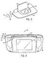
- FIG. 3 is a perspective view of an exemplary sun visor having a vanity mirror cover that may employ a hinge having a biased rotation axle.
- FIG. 4 is a perspective view of a vanity mirror assembly that may be utilized within the sun visor shown in FIG. 3 .
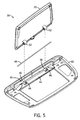
- FIG. 5 is an exploded view of the vanity mirror assembly shown in FIG. 4 .
- FIG. 6 is a rear perspective view of the vanity mirror assembly shown in FIG. 4 .
- FIG. 7 is a rear exploded view of the vanity mirror assembly shown in FIG. 4 .
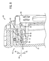
- FIG. 8 is a cross-sectional perspective view of the vanity mirror assembly, taken along line 8-8 of FIG. 6 .
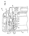
- FIG. 9 is a cross-sectional perspective view of the vanity mirror assembly, taken along line 9-9 of FIG. 6 .
- FIG. 10 is a cross-sectional perspective view of the vanity mirror assembly, taken along line 10-10 of FIG. 6 .
- FIG. 11 is a cross-sectional perspective view of the vanity mirror assembly, taken along line 11-11 of FIG. 6 .
- FIG. 12 is a cross-sectional view of the vanity mirror assembly, taken along line 12-12 of FIG. 6 .
- FIG. 13 is a cross-sectional view of the vanity mirror assembly, taken within line 13-13 of FIG. 10 , in which the vanity mirror cover is in a closed position.
- FIG. 14 is a cross-sectional view of the vanity mirror assembly, as shown in FIG. 13 , in which the vanity mirror cover is in a partially closed position.
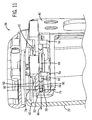
- FIG. 15 is a cross-sectional view of the vanity mirror assembly, as shown in FIG. 13 , in which the vanity mirror cover is in a partially open position.
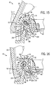
- FIG. 16 is a cross-sectional view of the vanity mirror assembly, as shown in FIG. 13 , in which the vanity mirror cover is in an open position.
- FIG. 1 is a perspective view of a motor vehicle 10 including one or more sun visors having vanity mirror covers.
- the vehicle 10 includes an interior 12 having a seat 14, an armrest 16 and a center console 18.
- the seat 14, the armrest 16, the center console 18, or other areas within the vehicle interior 12 may include doors configured to rotate with respect to a base structure.
- the vehicle 10 may include sun visors configured to shield vehicle occupants from sunlight.
- certain sun visor configurations include a vanity mirror having a cover configured to conceal the mirror when not in use.
- Certain vanity mirror covers are configured to rotate with respect to the sun visor to selectively expose and conceal the mirror.
- such vanity mirror covers include a hinge to facilitate rotation, which may be configured to bias the cover toward the closed and/or open positions.
- Certain embodiments of the present disclosure are configured to reduce the manufacturing costs, size and/or weight of hinge assemblies configured to bias the vanity mirror cover toward the open and/or closed positions.
- certain hinge assemblies include a follower and a cam disposed adjacent to the follower.
- the cam may be connected to a first surface such as the vanity mirror cover, while the follower is coupled to a second surface such as the visor.
- the cam is capable of translating relative to the follower along a vertical direction and rotating relative to the follower about a rotational axis.
- the hinge assembly also includes an axle disposed through the cam to facilitate rotation of the cam about the rotational axis. The axle is configured to bias the cam toward the follower along the vertical direction.
- the cam is contoured such that contact between the follower and a first portion of the cam induces the cam to rotate in a first direction, and contact between the follower and a second portion of the cam induces the cam to rotate in a second direction, opposite the first direction. In this manner, the force applied by the axle to the cam rotationally biases the cover toward the open and/or closed positions.
- FIG. 2 is a perspective view of a part of the interior 12 of the vehicle 10 of FIG. 1 .
- the vehicle interior 12 includes a sun visor 20 with a vanity mirror cover 22.
- the vanity mirror cover 22 is configured to rotate about a hinge assembly between an open position and a closed position.
- the hinge assembly employs certain unique features configured to bias the cover 22 toward the open and/or closed positions while reducing manufacturing costs and/or weight compared to typical configurations.
- the sun visor 20 may include other components including lights, controls, displays, etc.
- an overhead console 24 includes a storage compartment 26, such as a bin for housing sunglasses.
- the storage compartment 26 may include a rotatable door configured to enclose the compartment 26.
- Such configurations may employ a hinge mechanism similar to the embodiments described below.
- the hinge mechanism may function to bias the door toward the closed position as the door approaches the closed position and/or to bias the door toward the open position as the door approaches the open position.
- the hinge assembly described below may be employed within other devices or machines unrelated to vehicle interiors 12.
- FIG. 3 is a perspective view of an exemplary sun visor 20 having a vanity mirror cover 22 that may employ a hinge having a biased rotation axle.
- the vanity mirror cover 22 is in an open position exposing a mirror 30 within the visor 20.
- the hinge assembly may include certain features configured to bias the cover 22 toward the open position, thereby maintaining the cover 22 in the open position despite movement of the vehicle 10.
- the occupant may rotate the cover 22 in the direction 32 about a rotational axis 34. Because the cover 22 may be biased toward the open position, the occupant may have to overcome the bias to close the cover 22. However, at a certain point during rotation in the direction 32, the hinge assembly may transition to biasing the cover 22 toward the closed position.
- Such a configuration may maintain the cover 22 in the closed position during operation of the vehicle 10.
- the vanity mirror cover 22 may be opened by rotating the cover 22 in a direction 36 about the rotational axis 34.
- the hinge assembly may employ a biased rotation axle and a cam/follower configured to enable rotation of the cover 22 and establish the biases toward the open and closed positions.
- FIG. 4 is a perspective view of a vanity mirror assembly 38 that may be utilized within the sun visor 20 shown in FIG. 3 .
- the vanity mirror assembly 38 includes a frame 40 which may be secured (e.g., bonded, adhesively joined, bolted, etc.) to a body of the visor 20.
- the frame 40 serves to support the mirror 30 and the cover 22.
- a hinge assembly 42 serves to secure the cover 22 to the frame 40 while enabling rotation of the cover 22 with respect to the frame 40.
- the hinge assembly 42 also functions to bias the cover 22 toward the closed position as the cover 22 approaches the closed position, and to bias the cover 22 toward the open position as the cover 22 approaches the open position.
- the hinge assembly 42 is configured to hold the cover 22 in the closed position and the open position during operation of the vehicle 10 despite vibration and/or other forces and moments applied to the visor 20.
- FIG. 5 is an exploded view of the vanity mirror assembly 38 shown in FIG. 4 .
- the hinge assembly 42 includes a vanity cover support 44 including two recesses 46.
- the hinge assembly 42 also includes a rotation axle 48 which may be disposed within a groove 50 of the cover support 44.
- the hinge assembly 42 includes a pair of cams 52 rigidly coupled to the vanity cover 22.
- the axle 48 passes through openings within the cams 52, thereby securing the cover 22 to the cover support 44.
- the openings within the cams 52 may be aligned with the groove 50 of the cover support 44.
- the axle 48 may then be inserted though the groove 50 and the openings to mount the cover 22 to the frame 40.
- the axle 48 serves as a rotation axis for the cams 52 within the recesses 46. Furthermore, as discussed in detail below, the axle 48 may bias the cams 52 toward followers within the cover support 44. Because the cams 52 are contoured to induce rotation of the cover 22 toward the open and/or closed positions, the axle bias may serve to hold the cover 22 in the open and/or closed position, and/or facilitate the opening and/or closing operations. While two cams 52 and recesses 46 are shown in the present embodiment, it should be appreciated that more or fewer cams and recesses may be employed in alternative embodiments. For example, in certain configurations, 1, 2, 3, 4, 5, 6, or more cams 52 and recesses 46 may be utilized to secure the cover 22 to the frame 40 while facilitating rotation of the cover with respect to the frame.
- FIG. 6 is a rear perspective view of the vanity mirror assembly 38 shown in FIG. 4 .
- the axle 48 extends through the groove 50 within the cover support 44 and the cams 52 of the cover 22, thereby coupling the cover 22 to the frame 40.
- the cover support 44 includes follower assemblies 54 at the base of the recesses 46.
- the follower assemblies 54 are configured to support followers which engage the cams 52 to establish the biases toward the open and/or closed positions.
- the cover support 44 includes end caps 56 having axle carriers 58.
- axle carriers 58 are configured to block horizontal movement of the axle 48 (e.g., movement along an axis extending from the top of the assembly 38 to the bottom), while the end caps 56 are configured to block longitudinal movement of the axle 48 (e.g., movement along the rotational axis 34).
- an axle carrier 60 within a center portion 62 of the cover support 44 facilitates insertion of the axle 48, while enabling the axle to move in the vertical direction (e.g., movement along an axis extending from the front of the assembly 38 to the rear).
- the axle 48 serves as a pivot about which the cover 22 may rotate.
- the present embodiment facilitates a limited amount of vertical movement of the axle 48 within the groove 50 to enable the vertical position of the cams 52 to vary based on contact with the follower.
- the axle 48 is bent into a curved profile. This curved profile establishes a bending moment within the axle 48 that biases the cams 52 toward the followers of the follower assemblies 54.
- contact between the followers and the cams 52 creates a rotational bias that urges the cover 22 to transition to the open position and/or the closed position.
- FIG. 7 is a rear exploded view of the vanity mirror assembly 38 shown in FIG. 4 .
- the axle 48 has been removed from the groove 50 such that the axle carrier 60 is clearly visible.
- the openings within the cams 52 may be aligned with the groove 50 prior to insertion of the axle 48.
- the axle 48 is substantially straight prior to being bent by the shape of the end caps 56.
- the axle 48 may be pre-bent to establish a desired contact force between the followers and the cams 52.
- the cams 52 include a bearing surface 64 configured to contact the followers of the follower assemblies 54.
- the bearing surface 64 includes a first detent region 66, a second detent region 68 and a biasing region 70.
- the first detent region 68 is configured to capture the follower, thereby holding the cover 22 in the closed position.
- the follower transitions to the biasing region 70.
- the biasing region 70 includes a first portion configured to bias the cover toward the closed position, and a second portion configured to bias the cover toward the open position.
- the first portion is positioned adjacent to the first detent region 66, while the second portion is positioned adjacent to the second detent region 68.
- the cover 22 when the cover 22 is oriented closer to the closed position, the cover 22 is rotationally biased toward the closed position. Conversely, when the cover 22 is oriented closer to the open position, the cover 22 is rotationally biased toward the open position.
- the second detent region 68 captures the follower and holds the cover 22 in the open position. In this manner, the cover may be held in a desired position despite movement experienced by the vehicle 10 during operation.
- the biasing region 70 may serve to automatically transition the cover 22 to the open or closed position to reduce the possibility of the cover 22 remaining within an intermediate position.
- FIG. 8 is a cross-sectional perspective view of the vanity mirror assembly 38, taken along line 8-8 of FIG. 6 .
- the axle 48 is disposed within the groove 50 to facilitate rotation of the vanity cover 22 with respect to the frame 40.
- horizontal movement of the axle 48 is blocked by contact between the axle 48 and the axle carrier 60.
- the axle carrier 60 includes a first surface 72 and a second surface 74 disposed on opposite horizontal sides of the axle 48. Consequently, contact between the axle 48 and the first surface 72 blocks horizontal movement of the axle 48 along a direction 76, and contact between the axle 48 and the second surface 74 blocks horizontal movement of the axle 48 along a direction 78.
- the axle carrier 60 is configured to enable vertical movement in directions substantially perpendicular to directions 76 and 78.
- FIG. 9 is a cross-sectional perspective view of the vanity mirror assembly 38, taken along line 9-9 of FIG. 6 .
- a follower 80 is coupled to the follower assembly 54.
- the follower 80 is configured to engage the bearing surface 64 of the cam 52 to bias the cover 22 toward the open and/or closed positions.
- the groove 50 extends to the recess 46, thereby forming an axle support 82 adjacent to the cam 52.
- the axle support 82 enables vertical movement of the axle 48 in the directions 84 and 86. Because the axle 48 is coupled to the cam 52, the support 82 facilitates movement of the axle 48 in the vertical direction.
- the cam 52 may serve to hold the cover 22 in the open position, hold the cover 22 in the closed position, or bias the cover toward the open or closed position based on the region of the bearing surface 64 which contacts the follower 80.
- the biasing force induced by the axle 48 provides a sufficient contact force between the bearing surface and the follower 80 to induce the rotational biases and/or hold the cover in the desired position.
- FIG. 10 is a cross-sectional perspective view of the vanity mirror assembly 38, taken along line 10-10 of FIG. 6 .
- the axle 48 passes through an opening 88 within the cam 52 thereby enabling the cam 52 to rotate with respect to the follower 80, and biasing the cam 52 toward the follower 80 in the vertical direction 84.
- the follower 80 is positioned within the first detent region 66. Consequently, rotation of the cam 52 relative to the follower 80 is blocked by contact between the surfaces of the first detent region 66 and the follower 80.
- an occupant may apply a force to the cover 22 to establish a moment sufficient to rotate the cam 52 in the direction 36.
- the cam 52 rotates in the vertical direction 86 against the axle bias in the direction 84 due to contact between the follower 80 and the surfaces of the first detent region 66.
- the follower 80 transitions to the biasing region 70 of the bearing surface 64.
- the biasing region 70 includes a first portion adjacent to the first detent region 66 and a second portion adjacent to the second detent region 68. While the follower 80 contacts the first portion, the force induced by the axle 48 in the direction 84 will be redirected by the first portion to urge the cam 52 to rotate in the direction 32, thereby biasing the cover 22 toward the closed position.
- FIG. 11 is a cross-sectional perspective view of the vanity mirror assembly 38, taken along line 11-11 of FIG. 6 .
- the axle 48 is disposed within the groove 50 to facilitate rotation of the vanity cover 22 with respect to the frame 40.
- horizontal movement of the axle 48 is blocked by contact between the axle 48 and the axle carrier 58.
- the axle carrier 58 includes a first surface 90 and a second surface 92 disposed on opposite horizontal sides of the axle 48. Consequently, contact between the axle 48 and the first surface 90 blocks horizontal movement of the axle 48 along the direction 76, and contact between the axle 48 and the second surface 92 blocks horizontal movement of the axle 48 along the direction 78.
- axle 48 longitudinal movement of the axle 48 is blocked by contact between the end of the axle 48 and the inner surface of the end cap 56. As discussed in detail below, contact between the end cap 56 and the axle 48 induces the axle 48 to bend downward in the vertical direction 84, thereby applying a downward force on the cam 52 and establishing the axle bias.
- FIG. 12 is a cross-sectional view of the vanity mirror assembly 38, taken along line 12-12 of FIG. 6 .
- the axle 48 extends through the cams 52 and the cover support 44, thereby securing the cover 22 to the frame 40.
- contact between the cams 52 and the surrounding structure of the cover support 44 blocks movement of the cover 22 along the longitudinal axis of the axle 48.
- the cover 22 may translate in the vertical direction 84 and/or 86 as the bearing surface 64 of the cam 52 rotates along the follower 80.
- the shape of the end caps 56 induces the axle 48 to bend downward in the direction 84 at the ends.
- contact between an end portion 94 of the axle 48 and the end cap 56 forces the end portion 94 downward, thereby biasing a portion 96 of the axle 48 in contact with the cam 52 in the downward direction 84.
- the downward force from the axle portion 96 urges the cam 52 toward the follower, thereby providing the force which holds the cover 22 in the open and/or closed positions, and establishes the rotational biases.
- the cam 52 rotates, the axle may be driven upwards in the direction 86. Because the axle is supported at both ends, the upward motion is resisted by the downward bias of the bent axle 48.
- the center portion 98 is biased upward. Consequently, in the present embodiment, the cams 52 and follower supports 54 are positioned toward the ends 94 of the axle 48 to utilize the downward bias.
- the magnitude of the downward bias may be varied by adjusting the properties of the axle 48 and/or cover support 44.
- the thickness of the axle 48 will affect the resistance to bending. Consequently, a thicker axle 48 will apply a greater downward force than a thinner axle 48.
- the length, area moment of inertial, material properties, wear, among other factors may also affect the force applied by the axle 48 to the cams 52.
- the position of the cams 52 may affect the force applied by the axle. For example, cams 52 positioned closer to the ends 94 may experience a greater downward force than cams positioned closer to the center 98.
- the shape of the end caps 56 may alter the axle force.
- the downward force may be dependent on the slope of the end caps 56 adjacent to the axle 48. While the ends 94 of the axle 48 are not fixed to the end caps 56 in the present embodiment, it should be appreciated that alternative embodiments may employ end caps 56 which rigidly attach to the ends 94 of the axle 48. Such configurations may alter the bending profile of the axle 48, thereby affecting the torque profile of the hinge assembly 42.
- FIG. 13 is a cross-sectional view of the vanity mirror assembly 38, taken within line 13-13 of FIG. 10 , in which the vanity mirror cover 22 is in a closed position.
- the first detent region 66 is configured to capture the follower 80 to hold the cover 22 in the closed position.
- the follower 80 includes a first contact surface 100, a tip portion 102 and a second contact surface 104.
- the first detent region 66 includes a first contact surface 106, a tip portion 108 and a second contact surface 110.
- contact between the first contact surface 100 of the follower 80 and the first contact surface 106 of the first detent region 66 blocks rotation of the cover 22 in the direction 36.
- the vanity cover assembly includes certain features configured to limit rotation in the direction 32 once the cover has reached the closed position.
- the cover 22 While the follower 80 is captured by the first detent region 66, the cover 22 is in a stable position. In other words, any slight rotation of the cover 22 in the direction 32 or 36 will cause the cover 22 to return to the closed position. Consequently, the cover 22 may be held in the illustrated closed position despite vibration and other forces and moments that may be applied to the sun visor 20 during operation of the vehicle 10.
- the occupant may apply a force to the cover 22 inducing the cam 52 to rotate in the direction 36. Specifically, as the cam 52 rotates, contact between the first contact surface 106 of the first detent region 66 and the first contact surface 100 of the follower 80 drives the cam 52 upward in the vertical direction 86 against the downward bias of the axle 48.
- the force sufficient to induce the cover 22 to rotate away from the closed position may be dependent on the downward force of the axle 48, the shape of the first contact surface 100 of the follower 80 and/or the shape of the first contact surface 106 of the first detent region 66.
- FIG. 14 is a cross-sectional view of the vanity mirror assembly 38, as shown in FIG. 13 , in which the vanity mirror cover 22 is in a partially closed position.
- the axle 48 has translated upward within the axle support 82 from the position illustrated in FIG. 13 .
- the axle has moved a distance A along the vertical direction 86, thereby acting against the downward bias of the axle 48.
- the follower 80 will disengage the first detent portion 66 and contact the biasing region 70.
- the tip 102 of the follower 80 will contact a first portion 112 of the biasing region 70.
- FIG. 15 is a cross-sectional view of the vanity mirror assembly 38, as shown in FIG. 13 , in which the vanity mirror cover 22 is in a partially open position.
- the axle 48 is positioned a distance B along the vertical direction 86 from the position illustrated in FIG. 13 .
- the tip 102 of the follower 80 will transition between contact with the first portion 112 of the biasing region 70 to contact with a second portion 114. Due to the contour of the second portion 114, force applied by the axle 48 in the downward direction 84 is redirected to induce a rotation of the cam 52 in the direction 36, i.e., toward the open position.
- the cover 22 is in an unstable position. Therefore, if an occupant transitioning the cover 22 toward the open position releases the cover 22, the cover will automatically transition toward the open position. Furthermore, if an occupant is in the process of closing the cover 22 and releases the cover 22 at the illustrated orientation, the cover 22 will transition back to the open position.
- the rotational bias in the direction 36 caused by the downward force of the axle 48 is at least partially dependent on the shape of the second portion 114 of the biasing region 70. Therefore, the rotational bias may be adjusted by altering the shape of the second portion 114.
- the biasing region 70 may include a portion between the first portion 112 and the second portion 114 that produces substantially no rotational bias when contacted by the follower 80.
- FIG. 16 is a cross-sectional view of the vanity mirror assembly, as shown in FIG. 13 , in which the vanity mirror cover is in an open position.
- the second detent region 68 is configured to capture the follower 80 to hold the cover 22 in the open position.
- the second detent region 68 includes a first contact surface 116, a tip portion 118 and a second contact surface 120.
- contact between the first contact surface 100 of the follower 80 and the first contact surface 116 of the second detent region 68 blocks rotation of the cover 22 in the direction 32.
- contact between the second contact surface 104 of the follower 80 and the second contact surface 120 of the second detent region 68 may block movement of the cover 22 in the direction 36.
- the vanity cover assembly includes certain features configured to limit rotation in the direction 36 once the cover has reached the open position.
- the cover 22 While the follower 80 is captured by the second detent region 68, the cover 22 is in a stable position. In other words, any slight rotation of the cover 22 in the direction 32 or 36 will cause the cover 22 to return to the open position. Consequently, the cover 22 may be held in the illustrated open position despite vibration and other forces and moments that may be applied to the sun visor 20 during operation of the vehicle 10.
- the occupant may apply a force to the cover 22 inducing the cam 52 to rotate in the direction 32. Specifically, as the cam 52 rotates, contact between the second contact surface 120 of the second detent region 68 and the second contact surface 104 of the follower 80, drives the cam 52 upward in the vertical direction 86 against the downward bias of the axle 48.
- the force sufficient to induce the cover 22 to rotate away from the open position may be dependent on the downward force of the axle 48, the shape of the second contact surface 104 of the follower 80 and/or the shape of the second contact surface 120 of the second detent region 68.
Landscapes
- Engineering & Computer Science (AREA)
- Mechanical Engineering (AREA)
- Pivots And Pivotal Connections (AREA)
- Rear-View Mirror Devices That Are Mounted On The Exterior Of The Vehicle (AREA)
Description
- This application claims priority from and the benefit of
U.S. Provisional Application Serial No. 61/143,680 - The invention relates generally to a hinge assembly for a vehicle interior trim component.
- Many vehicles employ sun visors to shield occupants from sunlight which may otherwise distract the occupants during operation of the vehicle. For example, certain vehicles include sun visors positioned adjacent to a top portion of the windshield to facilitate access by a driver and/or front passenger. Many sun visors include a vanity mirror attached to an inner face of the sun visor which is visible to occupants when the visor is in a deployed position. In certain configurations, a cover may be employed to conceal and protect the vanity mirror when not in use. For example, the vanity mirror cover may be attached to the sun visor by a hinge that enables the cover to selectively expose and conceal the mirror via rotation of the cover with respect to the visor.
- As will be appreciated, typical rotating vanity cover assemblies include a hinge assembly configured to bias the cover toward the open position as the cover approaches the open position and/or to bias the cover toward the closed position as the cover approaches the closed position. In this manner, the hinge assembly may hold the cover in the open and/or closed positions despite movement of the vehicle. Unfortunately, typical hinge assemblies configured to bias the cover toward the open and/or closed positions are expensive to manufacture and assemble due to the number of parts typically employed for such configurations. In addition, such hinge assemblies may be unsuitable for use in thinner and/or lighter sun visors because they employ bulky components such as springs, pins, and other relative large parts.
-
US 4,993,772 discloses the preamble of claim 1 and describes a spring-loaded hinge assembly adapted for use in pivotally interconnected components, such as hinged or pivotal components in accessory assemblies in vehicle applications. The hinge assembly provides for at least a pair of predetermined relative rotational orientations, or detented positions, of the pivotally interconnected components. - The present invention relates to a hinge assembly including a follower and a cam disposed adjacent to the follower. The cam is capable of translating relative to the follower along a vertical direction and rotating relative to the follower about a rotational axis. The hinge assembly also includes an axle disposed through the cam to facilitate rotation of the cam about the rotational axis. The axle is configured to bias the cam toward the follower along the vertical direction.
- The present invention also relates to a hinge assembly including a follower, and a cam having an opening positioned about a rotational axis of the cam and a bearing surface configured to contact the follower. The hinge assembly also includes an axle disposed through the opening to facilitate rotation of the cam about the rotational axis. The axle is configured to bias the cam toward the follower along a vertical direction, and a portion of the bearing surface is contoured such that contact between the follower and the bearing surface induces the cam to rotate.
- The present invention further relates to a hinge assembly including a follower, and a cam having an opening positioned about a rotational axis of the cam and a bearing surface configured to contact the follower. The hinge assembly also includes an axle disposed through the opening to facilitate rotation of the cam about the rotational axis. The axle is configured to bias the cam toward the follower. The hinge assembly further includes an axle support configured to enable the axle to translate in a vertical direction relative to the follower such that contact between the bearing surface and the follower induces the cam to translate along the vertical direction in response to cam rotation.
-
FIG. 1 is a perspective view of an exemplary vehicle that may include one or more sun visors having vanity mirror covers. -
FIG. 2 is a perspective view of a part of the interior of the vehicle ofFIG. 1 . -
FIG. 3 is a perspective view of an exemplary sun visor having a vanity mirror cover that may employ a hinge having a biased rotation axle. -
FIG. 4 is a perspective view of a vanity mirror assembly that may be utilized within the sun visor shown inFIG. 3 . -
FIG. 5 is an exploded view of the vanity mirror assembly shown inFIG. 4 . -
FIG. 6 is a rear perspective view of the vanity mirror assembly shown inFIG. 4 . -
FIG. 7 is a rear exploded view of the vanity mirror assembly shown inFIG. 4 . -
FIG. 8 is a cross-sectional perspective view of the vanity mirror assembly, taken along line 8-8 ofFIG. 6 . -
FIG. 9 is a cross-sectional perspective view of the vanity mirror assembly, taken along line 9-9 ofFIG. 6 . -
FIG. 10 is a cross-sectional perspective view of the vanity mirror assembly, taken along line 10-10 ofFIG. 6 . -
FIG. 11 is a cross-sectional perspective view of the vanity mirror assembly, taken along line 11-11 ofFIG. 6 . -
FIG. 12 is a cross-sectional view of the vanity mirror assembly, taken along line 12-12 ofFIG. 6 . -
FIG. 13 is a cross-sectional view of the vanity mirror assembly, taken within line 13-13 ofFIG. 10 , in which the vanity mirror cover is in a closed position. -
FIG. 14 is a cross-sectional view of the vanity mirror assembly, as shown inFIG. 13 , in which the vanity mirror cover is in a partially closed position. -
FIG. 15 is a cross-sectional view of the vanity mirror assembly, as shown inFIG. 13 , in which the vanity mirror cover is in a partially open position. -
FIG. 16 is a cross-sectional view of the vanity mirror assembly, as shown inFIG. 13 , in which the vanity mirror cover is in an open position. -
FIG. 1 is a perspective view of amotor vehicle 10 including one or more sun visors having vanity mirror covers. As illustrated, thevehicle 10 includes aninterior 12 having aseat 14, anarmrest 16 and acenter console 18. As discussed in detail below, theseat 14, thearmrest 16, thecenter console 18, or other areas within thevehicle interior 12 may include doors configured to rotate with respect to a base structure. For example, in certain embodiments, thevehicle 10 may include sun visors configured to shield vehicle occupants from sunlight. As will be appreciated, certain sun visor configurations include a vanity mirror having a cover configured to conceal the mirror when not in use. Certain vanity mirror covers are configured to rotate with respect to the sun visor to selectively expose and conceal the mirror. As will be appreciated, such vanity mirror covers include a hinge to facilitate rotation, which may be configured to bias the cover toward the closed and/or open positions. - Certain embodiments of the present disclosure are configured to reduce the manufacturing costs, size and/or weight of hinge assemblies configured to bias the vanity mirror cover toward the open and/or closed positions. For example, certain hinge assemblies include a follower and a cam disposed adjacent to the follower. The cam may be connected to a first surface such as the vanity mirror cover, while the follower is coupled to a second surface such as the visor. The cam is capable of translating relative to the follower along a vertical direction and rotating relative to the follower about a rotational axis. The hinge assembly also includes an axle disposed through the cam to facilitate rotation of the cam about the rotational axis. The axle is configured to bias the cam toward the follower along the vertical direction. In certain configurations, the cam is contoured such that contact between the follower and a first portion of the cam induces the cam to rotate in a first direction, and contact between the follower and a second portion of the cam induces the cam to rotate in a second direction, opposite the first direction. In this manner, the force applied by the axle to the cam rotationally biases the cover toward the open and/or closed positions.
-
FIG. 2 is a perspective view of a part of theinterior 12 of thevehicle 10 ofFIG. 1 . As illustrated, thevehicle interior 12 includes asun visor 20 with avanity mirror cover 22. As discussed in detail below, thevanity mirror cover 22 is configured to rotate about a hinge assembly between an open position and a closed position. The hinge assembly employs certain unique features configured to bias thecover 22 toward the open and/or closed positions while reducing manufacturing costs and/or weight compared to typical configurations. As will be appreciated, thesun visor 20 may include other components including lights, controls, displays, etc. - In addition, the hinge assembly described below may be employed within other areas of the
vehicle interior 12. For example, anoverhead console 24 includes astorage compartment 26, such as a bin for housing sunglasses. In certain configurations, thestorage compartment 26 may include a rotatable door configured to enclose thecompartment 26. Such configurations may employ a hinge mechanism similar to the embodiments described below. For example, the hinge mechanism may function to bias the door toward the closed position as the door approaches the closed position and/or to bias the door toward the open position as the door approaches the open position. It should also be appreciated that the hinge assembly described below may be employed within other devices or machines unrelated tovehicle interiors 12. -
FIG. 3 is a perspective view of anexemplary sun visor 20 having avanity mirror cover 22 that may employ a hinge having a biased rotation axle. As illustrated, thevanity mirror cover 22 is in an open position exposing amirror 30 within thevisor 20. As discussed in detail below, the hinge assembly may include certain features configured to bias thecover 22 toward the open position, thereby maintaining thecover 22 in the open position despite movement of thevehicle 10. When an occupant desires to close thecover 22, the occupant may rotate thecover 22 in thedirection 32 about arotational axis 34. Because thecover 22 may be biased toward the open position, the occupant may have to overcome the bias to close thecover 22. However, at a certain point during rotation in thedirection 32, the hinge assembly may transition to biasing thecover 22 toward the closed position. Such a configuration may maintain thecover 22 in the closed position during operation of thevehicle 10. Thevanity mirror cover 22 may be opened by rotating thecover 22 in adirection 36 about therotational axis 34. As discussed in detail below, the hinge assembly may employ a biased rotation axle and a cam/follower configured to enable rotation of thecover 22 and establish the biases toward the open and closed positions. -
FIG. 4 is a perspective view of avanity mirror assembly 38 that may be utilized within thesun visor 20 shown inFIG. 3 . As illustrated, thevanity mirror assembly 38 includes aframe 40 which may be secured (e.g., bonded, adhesively joined, bolted, etc.) to a body of thevisor 20. Theframe 40 serves to support themirror 30 and thecover 22. As previously discussed, ahinge assembly 42 serves to secure thecover 22 to theframe 40 while enabling rotation of thecover 22 with respect to theframe 40. As discussed in detail below, thehinge assembly 42 also functions to bias thecover 22 toward the closed position as thecover 22 approaches the closed position, and to bias thecover 22 toward the open position as thecover 22 approaches the open position. In addition, thehinge assembly 42 is configured to hold thecover 22 in the closed position and the open position during operation of thevehicle 10 despite vibration and/or other forces and moments applied to thevisor 20. -
FIG. 5 is an exploded view of thevanity mirror assembly 38 shown inFIG. 4 . As illustrated, thehinge assembly 42 includes avanity cover support 44 including tworecesses 46. Thehinge assembly 42 also includes arotation axle 48 which may be disposed within agroove 50 of thecover support 44. Furthermore, thehinge assembly 42 includes a pair ofcams 52 rigidly coupled to thevanity cover 22. As discussed in detail below, theaxle 48 passes through openings within thecams 52, thereby securing thecover 22 to thecover support 44. For example, during assembly of thevanity mirror assembly 38, the openings within thecams 52 may be aligned with thegroove 50 of thecover support 44. Theaxle 48 may then be inserted though thegroove 50 and the openings to mount thecover 22 to theframe 40. In this manner, theaxle 48 serves as a rotation axis for thecams 52 within therecesses 46. Furthermore, as discussed in detail below, theaxle 48 may bias thecams 52 toward followers within thecover support 44. Because thecams 52 are contoured to induce rotation of thecover 22 toward the open and/or closed positions, the axle bias may serve to hold thecover 22 in the open and/or closed position, and/or facilitate the opening and/or closing operations. While twocams 52 and recesses 46 are shown in the present embodiment, it should be appreciated that more or fewer cams and recesses may be employed in alternative embodiments. For example, in certain configurations, 1, 2, 3, 4, 5, 6, ormore cams 52 and recesses 46 may be utilized to secure thecover 22 to theframe 40 while facilitating rotation of the cover with respect to the frame. -
FIG. 6 is a rear perspective view of thevanity mirror assembly 38 shown inFIG. 4 . As illustrated, theaxle 48 extends through thegroove 50 within thecover support 44 and thecams 52 of thecover 22, thereby coupling thecover 22 to theframe 40. Furthermore, thecover support 44 includesfollower assemblies 54 at the base of therecesses 46. Thefollower assemblies 54 are configured to support followers which engage thecams 52 to establish the biases toward the open and/or closed positions. In the present configuration, thecover support 44 includes end caps 56 havingaxle carriers 58. As discussed in detail below, theaxle carriers 58 are configured to block horizontal movement of the axle 48 (e.g., movement along an axis extending from the top of theassembly 38 to the bottom), while the end caps 56 are configured to block longitudinal movement of the axle 48 (e.g., movement along the rotational axis 34). In addition, anaxle carrier 60 within acenter portion 62 of thecover support 44 facilitates insertion of theaxle 48, while enabling the axle to move in the vertical direction (e.g., movement along an axis extending from the front of theassembly 38 to the rear). - In the present configuration, the
axle 48 serves as a pivot about which thecover 22 may rotate. As discussed in detail below, the present embodiment facilitates a limited amount of vertical movement of theaxle 48 within thegroove 50 to enable the vertical position of thecams 52 to vary based on contact with the follower. Furthermore, due to the shape of the end caps 56, theaxle 48 is bent into a curved profile. This curved profile establishes a bending moment within theaxle 48 that biases thecams 52 toward the followers of thefollower assemblies 54. In the present embodiment, contact between the followers and thecams 52 creates a rotational bias that urges thecover 22 to transition to the open position and/or the closed position. -
FIG. 7 is a rear exploded view of thevanity mirror assembly 38 shown inFIG. 4 . As illustrated, theaxle 48 has been removed from thegroove 50 such that theaxle carrier 60 is clearly visible. As previously discussed, the openings within thecams 52 may be aligned with thegroove 50 prior to insertion of theaxle 48. In the present configuration, theaxle 48 is substantially straight prior to being bent by the shape of the end caps 56. However, in alternative embodiments, theaxle 48 may be pre-bent to establish a desired contact force between the followers and thecams 52. - As illustrated, the
cams 52 include a bearingsurface 64 configured to contact the followers of thefollower assemblies 54. In the present configuration, the bearingsurface 64 includes afirst detent region 66, asecond detent region 68 and a biasingregion 70. As discussed in detail below, thefirst detent region 68 is configured to capture the follower, thereby holding thecover 22 in the closed position. As the occupant applies a sufficient moment to thecover 22 to induce the cover to rotate away from the closed position, the follower transitions to the biasingregion 70. In the present configuration, the biasingregion 70 includes a first portion configured to bias the cover toward the closed position, and a second portion configured to bias the cover toward the open position. The first portion is positioned adjacent to thefirst detent region 66, while the second portion is positioned adjacent to thesecond detent region 68. In this configuration, when thecover 22 is oriented closer to the closed position, thecover 22 is rotationally biased toward the closed position. Conversely, when thecover 22 is oriented closer to the open position, thecover 22 is rotationally biased toward the open position. Once the cover has been transitioned to the open position, thesecond detent region 68 captures the follower and holds thecover 22 in the open position. In this manner, the cover may be held in a desired position despite movement experienced by thevehicle 10 during operation. Furthermore, the biasingregion 70 may serve to automatically transition thecover 22 to the open or closed position to reduce the possibility of thecover 22 remaining within an intermediate position. -
FIG. 8 is a cross-sectional perspective view of thevanity mirror assembly 38, taken along line 8-8 ofFIG. 6 . As illustrated, theaxle 48 is disposed within thegroove 50 to facilitate rotation of thevanity cover 22 with respect to theframe 40. As previously discussed, horizontal movement of theaxle 48 is blocked by contact between theaxle 48 and theaxle carrier 60. Specifically, theaxle carrier 60 includes afirst surface 72 and asecond surface 74 disposed on opposite horizontal sides of theaxle 48. Consequently, contact between theaxle 48 and thefirst surface 72 blocks horizontal movement of theaxle 48 along adirection 76, and contact between theaxle 48 and thesecond surface 74 blocks horizontal movement of theaxle 48 along adirection 78. However, as discussed in detail below, theaxle carrier 60 is configured to enable vertical movement in directions substantially perpendicular todirections -
FIG. 9 is a cross-sectional perspective view of thevanity mirror assembly 38, taken along line 9-9 ofFIG. 6 . As illustrated, afollower 80 is coupled to thefollower assembly 54. As previously discussed, thefollower 80 is configured to engage the bearingsurface 64 of thecam 52 to bias thecover 22 toward the open and/or closed positions. In the present configuration, thegroove 50 extends to therecess 46, thereby forming anaxle support 82 adjacent to thecam 52. Theaxle support 82 enables vertical movement of theaxle 48 in thedirections axle 48 is coupled to thecam 52, thesupport 82 facilitates movement of theaxle 48 in the vertical direction. For example, as theaxle 48 biases thecam 52 toward thefollower 80, rotation of thecam 52 induces thecam 52 to move in thedirection 84 and/or 86 based on the profile of the bearingsurface 64. As previously discussed, thecam 52 may serve to hold thecover 22 in the open position, hold thecover 22 in the closed position, or bias the cover toward the open or closed position based on the region of the bearingsurface 64 which contacts thefollower 80. In the present embodiment, the biasing force induced by theaxle 48 provides a sufficient contact force between the bearing surface and thefollower 80 to induce the rotational biases and/or hold the cover in the desired position. -
FIG. 10 is a cross-sectional perspective view of thevanity mirror assembly 38, taken along line 10-10 ofFIG. 6 . As illustrated, theaxle 48 passes through anopening 88 within thecam 52 thereby enabling thecam 52 to rotate with respect to thefollower 80, and biasing thecam 52 toward thefollower 80 in thevertical direction 84. In the illustrated closed position, thefollower 80 is positioned within thefirst detent region 66. Consequently, rotation of thecam 52 relative to thefollower 80 is blocked by contact between the surfaces of thefirst detent region 66 and thefollower 80. To rotate thecover 22 toward the open position, an occupant may apply a force to thecover 22 to establish a moment sufficient to rotate thecam 52 in thedirection 36. Specifically, rotation of thecam 52 about theaxle 48 will induce thecam 52 to translate in thevertical direction 86 against the axle bias in thedirection 84 due to contact between thefollower 80 and the surfaces of thefirst detent region 66. As thecam 52 moves in thedirection 86 and rotates in thedirection 36, thefollower 80 transitions to the biasingregion 70 of the bearingsurface 64. As previously discussed, the biasingregion 70 includes a first portion adjacent to thefirst detent region 66 and a second portion adjacent to thesecond detent region 68. While thefollower 80 contacts the first portion, the force induced by theaxle 48 in thedirection 84 will be redirected by the first portion to urge thecam 52 to rotate in thedirection 32, thereby biasing thecover 22 toward the closed position. Conversely, while thefollower 80 contacts the second portion, the force induced by theaxle 48 in thedirection 84 will be redirected by the second portion to urge thecam 52 to rotate in thedirection 36, thereby biasing thecover 22 toward the open position. Once thecover 22 has rotated to the closed position, thefollower 80 will engage thesecond detent region 68, thereby holding thecover 22 in the closed position. -
FIG. 11 is a cross-sectional perspective view of thevanity mirror assembly 38, taken along line 11-11 ofFIG. 6 . As illustrated, theaxle 48 is disposed within thegroove 50 to facilitate rotation of thevanity cover 22 with respect to theframe 40. As previously discussed, horizontal movement of theaxle 48 is blocked by contact between theaxle 48 and theaxle carrier 58. Specifically, theaxle carrier 58 includes afirst surface 90 and asecond surface 92 disposed on opposite horizontal sides of theaxle 48. Consequently, contact between theaxle 48 and thefirst surface 90 blocks horizontal movement of theaxle 48 along thedirection 76, and contact between theaxle 48 and thesecond surface 92 blocks horizontal movement of theaxle 48 along thedirection 78. In addition, longitudinal movement of theaxle 48 is blocked by contact between the end of theaxle 48 and the inner surface of theend cap 56. As discussed in detail below, contact between theend cap 56 and theaxle 48 induces theaxle 48 to bend downward in thevertical direction 84, thereby applying a downward force on thecam 52 and establishing the axle bias. -
FIG. 12 is a cross-sectional view of thevanity mirror assembly 38, taken along line 12-12 ofFIG. 6 . As illustrated, theaxle 48 extends through thecams 52 and thecover support 44, thereby securing thecover 22 to theframe 40. In addition, contact between thecams 52 and the surrounding structure of thecover support 44 blocks movement of thecover 22 along the longitudinal axis of theaxle 48. However, as previously discussed, thecover 22 may translate in thevertical direction 84 and/or 86 as the bearingsurface 64 of thecam 52 rotates along thefollower 80. - As previously discussed, the shape of the end caps 56 induces the
axle 48 to bend downward in thedirection 84 at the ends. As illustrated, contact between anend portion 94 of theaxle 48 and theend cap 56 forces theend portion 94 downward, thereby biasing aportion 96 of theaxle 48 in contact with thecam 52 in thedownward direction 84. As will be appreciated, the downward force from theaxle portion 96 urges thecam 52 toward the follower, thereby providing the force which holds thecover 22 in the open and/or closed positions, and establishes the rotational biases. As discussed in detail below, when thecam 52 rotates, the axle may be driven upwards in thedirection 86. Because the axle is supported at both ends, the upward motion is resisted by the downward bias of thebent axle 48. In addition, as theaxle 48 bends, thecenter portion 98 is biased upward. Consequently, in the present embodiment, thecams 52 and follower supports 54 are positioned toward theends 94 of theaxle 48 to utilize the downward bias. - As will be appreciated, the magnitude of the downward bias may be varied by adjusting the properties of the
axle 48 and/or coversupport 44. For example, the thickness of theaxle 48 will affect the resistance to bending. Consequently, athicker axle 48 will apply a greater downward force than athinner axle 48. In addition, the length, area moment of inertial, material properties, wear, among other factors, may also affect the force applied by theaxle 48 to thecams 52. In addition, as previously discussed, the position of thecams 52 may affect the force applied by the axle. For example,cams 52 positioned closer to theends 94 may experience a greater downward force than cams positioned closer to thecenter 98. Furthermore, the shape of the end caps 56 may alter the axle force. For example, the downward force may be dependent on the slope of the end caps 56 adjacent to theaxle 48. While the ends 94 of theaxle 48 are not fixed to the end caps 56 in the present embodiment, it should be appreciated that alternative embodiments may employend caps 56 which rigidly attach to theends 94 of theaxle 48. Such configurations may alter the bending profile of theaxle 48, thereby affecting the torque profile of thehinge assembly 42. -
FIG. 13 is a cross-sectional view of thevanity mirror assembly 38, taken within line 13-13 ofFIG. 10 , in which thevanity mirror cover 22 is in a closed position. As previously discussed, thefirst detent region 66 is configured to capture thefollower 80 to hold thecover 22 in the closed position. As illustrated, thefollower 80 includes afirst contact surface 100, atip portion 102 and asecond contact surface 104. Correspondingly, thefirst detent region 66 includes afirst contact surface 106, atip portion 108 and asecond contact surface 110. As will be appreciated, contact between thefirst contact surface 100 of thefollower 80 and thefirst contact surface 106 of thefirst detent region 66 blocks rotation of thecover 22 in thedirection 36. Similarly, contact between thesecond contact surface 104 of thefollower 80 and thesecond contact surface 110 of thefirst detent region 66 may block movement of thecover 22 in thedirection 32. However, in certain embodiments, the vanity cover assembly includes certain features configured to limit rotation in thedirection 32 once the cover has reached the closed position. - While the
follower 80 is captured by thefirst detent region 66, thecover 22 is in a stable position. In other words, any slight rotation of thecover 22 in thedirection cover 22 to return to the closed position. Consequently, thecover 22 may be held in the illustrated closed position despite vibration and other forces and moments that may be applied to thesun visor 20 during operation of thevehicle 10. To open thecover 22, the occupant may apply a force to thecover 22 inducing thecam 52 to rotate in thedirection 36. Specifically, as thecam 52 rotates, contact between thefirst contact surface 106 of thefirst detent region 66 and thefirst contact surface 100 of thefollower 80 drives thecam 52 upward in thevertical direction 86 against the downward bias of theaxle 48. As will be appreciated, the force sufficient to induce thecover 22 to rotate away from the closed position may be dependent on the downward force of theaxle 48, the shape of thefirst contact surface 100 of thefollower 80 and/or the shape of thefirst contact surface 106 of thefirst detent region 66. -
FIG. 14 is a cross-sectional view of thevanity mirror assembly 38, as shown inFIG. 13 , in which thevanity mirror cover 22 is in a partially closed position. As illustrated, while in the partially closed position, theaxle 48 has translated upward within theaxle support 82 from the position illustrated inFIG. 13 . Specifically, the axle has moved a distance A along thevertical direction 86, thereby acting against the downward bias of theaxle 48. As an occupant rotates thecover 22 toward the open position, thefollower 80 will disengage thefirst detent portion 66 and contact the biasingregion 70. As a result, thetip 102 of thefollower 80 will contact afirst portion 112 of the biasingregion 70. Due to the contour of thefirst portion 112, force applied by theaxle 48 in thedownward direction 84 is redirected to induce a rotation of thecam 52 in thedirection 32, i.e., toward the closed position. Consequently, in the presently illustrated orientation, thecover 22 is in an unstable position. Therefore, if an occupant transitioning thecover 22 toward the open position releases thecover 22, the cover will transition back toward the closed position. Furthermore, if an occupant is in the process of closing thecover 22, the occupant may release thecover 22, and thecover 22 will transition toward the closed position automatically. The rotational bias in thedirection 32 caused by the downward force of theaxle 48 is at least partially dependent on the shape of thefirst portion 112 of the biasingregion 70. Therefore, the rotational bias may be adjusted by altering the shape of thefirst portion 112. -
FIG. 15 is a cross-sectional view of thevanity mirror assembly 38, as shown inFIG. 13 , in which thevanity mirror cover 22 is in a partially open position. As illustrated, while in the partially open position, theaxle 48 is positioned a distance B along thevertical direction 86 from the position illustrated inFIG. 13 . As an occupant continues to rotate thecover 22 toward the open position, thetip 102 of thefollower 80 will transition between contact with thefirst portion 112 of the biasingregion 70 to contact with asecond portion 114. Due to the contour of thesecond portion 114, force applied by theaxle 48 in thedownward direction 84 is redirected to induce a rotation of thecam 52 in thedirection 36, i.e., toward the open position. Consequently, in the presently illustrated orientation, thecover 22 is in an unstable position. Therefore, if an occupant transitioning thecover 22 toward the open position releases thecover 22, the cover will automatically transition toward the open position. Furthermore, if an occupant is in the process of closing thecover 22 and releases thecover 22 at the illustrated orientation, thecover 22 will transition back to the open position. The rotational bias in thedirection 36 caused by the downward force of theaxle 48 is at least partially dependent on the shape of thesecond portion 114 of the biasingregion 70. Therefore, the rotational bias may be adjusted by altering the shape of thesecond portion 114. As will be appreciated, the biasingregion 70 may include a portion between thefirst portion 112 and thesecond portion 114 that produces substantially no rotational bias when contacted by thefollower 80. -
FIG. 16 is a cross-sectional view of the vanity mirror assembly, as shown inFIG. 13 , in which the vanity mirror cover is in an open position. As previously discussed, thesecond detent region 68 is configured to capture thefollower 80 to hold thecover 22 in the open position. As illustrated, thesecond detent region 68 includes afirst contact surface 116, atip portion 118 and asecond contact surface 120. As will be appreciated, contact between thefirst contact surface 100 of thefollower 80 and thefirst contact surface 116 of thesecond detent region 68 blocks rotation of thecover 22 in thedirection 32. Similarly, contact between thesecond contact surface 104 of thefollower 80 and thesecond contact surface 120 of thesecond detent region 68 may block movement of thecover 22 in thedirection 36. However, in certain embodiments, the vanity cover assembly includes certain features configured to limit rotation in thedirection 36 once the cover has reached the open position. - While the
follower 80 is captured by thesecond detent region 68, thecover 22 is in a stable position. In other words, any slight rotation of thecover 22 in thedirection cover 22 to return to the open position. Consequently, thecover 22 may be held in the illustrated open position despite vibration and other forces and moments that may be applied to thesun visor 20 during operation of thevehicle 10. To close thecover 22, the occupant may apply a force to thecover 22 inducing thecam 52 to rotate in thedirection 32. Specifically, as thecam 52 rotates, contact between thesecond contact surface 120 of thesecond detent region 68 and thesecond contact surface 104 of thefollower 80, drives thecam 52 upward in thevertical direction 86 against the downward bias of theaxle 48. As will be appreciated, the force sufficient to induce thecover 22 to rotate away from the open position may be dependent on the downward force of theaxle 48, the shape of thesecond contact surface 104 of thefollower 80 and/or the shape of thesecond contact surface 120 of thesecond detent region 68. - While only certain features and embodiments of the invention have been illustrated and described, many modifications and changes may occur to those skilled in the art (e.g., variations in sizes, dimensions, structures, shapes and proportions of the various elements, values of parameters (e.g., temperatures, pressures, etc.), mounting arrangements, use of materials, colors, orientations, etc.) without materially departing from the novel teachings and advantages of the subject matter recited in the claims. The order or sequence of any process or method steps may be varied or re-sequenced according to alternative embodiments. It is, therefore, to be understood that the appended claims are intended to cover all such modifications and changes. Furthermore, in an effort to provide a concise description of the exemplary embodiments, all features of an actual implementation may not have been described (i.e., those unrelated to the presently contemplated best mode of carrying out the invention, or those unrelated to enabling the claimed invention). It should be appreciated that in the development of any such actual implementation, as in any engineering or design project, numerous implementation specific decisions may be made. Such a development effort might be complex and time consuming, but would nevertheless be a routine undertaking of design, fabrication, and manufacture for those of ordinary skill having the benefit of this disclosure, without undue experimentation.
Claims (15)
- A vehicle interior trim component hinge assembly (42), comprising:a follower (80);a cam (52) disposed adjacent to the follower (80), wherein the cam (52) is capable of translating relative to the follower (80) along a vertical direction and rotating relative to the follower (80) about a rotational axis; andan axle (48) disposed through the cam (52) to facilitate rotation of the cam (52) about the rotational axis,characterized in that the axle (48) is configured to bias the cam (52) toward the follower (80) along the vertical direction.
- The vehicle interior trim component hinge assembly (42) of claim 1, wherein a portion of the cam (52) is contoured such that contact between the follower and the cam (52) induces the cam (52) to rotate.
- The vehicle interior trim component hinge assembly (42) of claim 2, wherein the cam (52) is contoured such that contact between the follower and a first portion of the cam (52) induces the cam (52) to rotate in a first direction, and contact between the follower and a second portion of the cam (52) induces the cam (52) to rotate in a second direction, opposite the first direction.
- The vehicle interior trim component hinge assembly (42) of claim 1, wherein the cam (52) comprises at least one detent region having detent surfaces configured to capture the follower and bias the cam (52) toward an orientation aligned with the detent region.
- The vehicle interior trim component hinge assembly (42) of claim 3, wherein the cam (52) comprises a first detent region adjacent to the first portion along the first direction, and a second detent region adjacent to the second portion along the second direction, wherein the first and second detent regions include detent surfaces configured to capture the follower (80) and bias the cam toward an orientation aligned with the respective detent region.
- The vehicle interior trim component hinge assembly (42) of claim 1, comprising a plurality of followers (80) and a corresponding plurality of cams, wherein the axle is disposed through each cam to facilitate rotation of each cam about the respective rotational axis.
- The vehicle interior trim component hinge assembly (42) of claim 1, wherein:the cam (52) has an opening positioned about the rotational axis of the cam (52), and a bearing surface (64) configured to contact the follower (80);the axle (48) disposed through the opening to facilitate rotation of the cam (52) about the rotational axis, wherein the axle (48) is configured to bias the cam (52) toward the follower (80) along the vertical direction, and a portion of the bearing surface (64) is contoured such that contact between the follower (80) and the bearing surface (64) induces the cam to rotate.
- The vehicle interior trim component hinge assembly (42) of claim 7, wherein the bearing surface (64) is contoured such that contact between the follower (80) and a first portion of the bearing surface (64) induces the cam (52) to rotate in a first direction, and contact between the follower (80) and a second portion of the bearing surface (64) induces the cam (52) to rotate in a second direction, opposite the first direction.
- The vehicle interior trim component hinge assembly (42) of claim 7, wherein the bearing surface (64) comprises at least one detent region having detent surfaces configured to capture the follower (80) and bias the cam (52) toward an orientation aligned with the detent region.
- The vehicle interior trim component hinge assembly (42) of claim 8, wherein the bearing surface (64) comprises a first detent region adjacent to the first portion along the first direction, and a second detent region adjacent to the second portion along the second direction, wherein the first and second detent regions include detent surfaces configured to capture the follower and bias the cam (52) toward an orientation aligned with the respective detent region.
- The vehicle interior trim component hinge assembly (42) of claim 1, wherein:the cam (52) has an opening positioned about the rotational axis of the cam (52), and a bearing surface (64) configured to contact the follower (80);the axle (48) disposed through the opening to facilitate rotation of the cam (52) about the rotational axis, wherein the axle (48) is configured to bias the cam (52) toward the follower (80); andan axle support configured to enable the axle (48) to translate in the vertical direction relative to the follower (80) such that contact between the bearing surface (64) and the follower (80) induces the cam (52) to translate along the vertical direction in response to cam rotation.
- The vehicle interior trim component hinge assembly (42) of claim 11, wherein a portion of the bearing surface (64) is contoured such that contact between the follower (80) and the bearing surface (64) induces the cam (52) to rotate.
- The vehicle interior trim component hinge assembly (42) of claim 12, wherein the bearing surface (64) is contoured such that contact between the follower (80) and a first portion of the bearing surface (64) induces the cam (52) to rotate in a first direction, and contact between the follower (80) and a second portion of the bearing surface (64) induces the cam (52) to rotate in a second direction, opposite the first direction.
- The vehicle interior trim component hinge assembly (42) of claim 11, wherein the bearing surface (64) comprises at least one detent region having detent surfaces configured to capture the follower (80) and bias the cam (52) toward an orientation aligned with the detent region.
- The vehicle interior trim component hinge assembly (42) of claim 13, wherein the bearing surface (64) comprises a first detent region adjacent to the first portion along the first direction, and a second detent region adjacent to the second portion along the second direction, wherein the first and second detent regions include detent surfaces configured to capture the follower (80) and bias the cam (52) toward an orientation aligned with the respective detent region.
Priority Applications (1)
| Application Number | Priority Date | Filing Date | Title |
|---|---|---|---|
| PL10700095T PL2376302T3 (en) | 2009-01-09 | 2010-01-08 | Hinge assembly for vehicle interior trim component |
Applications Claiming Priority (2)
| Application Number | Priority Date | Filing Date | Title |
|---|---|---|---|
| US14368009P | 2009-01-09 | 2009-01-09 | |
| PCT/US2010/020535 WO2010081030A1 (en) | 2009-01-09 | 2010-01-08 | Hinge assembly for vehicle interior trim component |
Publications (2)
| Publication Number | Publication Date |
|---|---|
| EP2376302A1 EP2376302A1 (en) | 2011-10-19 |
| EP2376302B1 true EP2376302B1 (en) | 2013-08-28 |
Family
ID=41785792
Family Applications (1)
| Application Number | Title | Priority Date | Filing Date |
|---|---|---|---|
| EP10700095.2A Not-in-force EP2376302B1 (en) | 2009-01-09 | 2010-01-08 | Hinge assembly for vehicle interior trim component |
Country Status (7)
| Country | Link |
|---|---|
| US (1) | US8701250B2 (en) |
| EP (1) | EP2376302B1 (en) |
| JP (1) | JP5266398B2 (en) |
| KR (1) | KR101371551B1 (en) |
| CN (1) | CN102307741B (en) |
| PL (1) | PL2376302T3 (en) |
| WO (1) | WO2010081030A1 (en) |
Families Citing this family (2)
| Publication number | Priority date | Publication date | Assignee | Title |
|---|---|---|---|---|
| PL413125A1 (en) * | 2015-07-14 | 2017-01-16 | Vts Spółka Z Ograniczoną Odpowiedzialnością | Hinge |
| DE102019119344A1 (en) | 2019-07-17 | 2021-01-21 | Daimay France Sas | Sun visor for a vehicle and method of manufacturing the same |
Family Cites Families (17)
| Publication number | Priority date | Publication date | Assignee | Title |
|---|---|---|---|---|
| US2132266A (en) * | 1936-08-05 | 1938-10-04 | Emil B G Lefevre | Gooseneck concealed hinge |
| GB2177057A (en) | 1985-07-04 | 1987-01-14 | John Connor | Vehicle sun visor |
| US4715644A (en) * | 1986-09-22 | 1987-12-29 | Irvin Industries, Inc. | Spring-loaded hinge assembly for vehicle accessories |
| FR2647733B1 (en) | 1989-06-06 | 1991-09-20 | Rockwell Abs France | MIRROR CASSETTE FOR SUN VISOR, ESPECIALLY IN AN AUTOMOBILE INTERIOR |
| US4993772A (en) * | 1990-02-20 | 1991-02-19 | Irvin Automotive Products, Inc. | Spring-loaded, dual-action hinge assembly for vehicle accessories |
| JPH0474118U (en) * | 1990-11-09 | 1992-06-29 | ||
| NO914165L (en) * | 1991-10-23 | 1993-04-26 | Grorud Jernvarefab As | PROCEDURE FOR STORAGE AND ASSEMBLY OF HOLES FOR CABINETS, FURNITURE OR SIMILAR, AND DEVICE FOR AA THAT CONNECTION BETWEEN HOUSING END PARTS OF CONSTRUCTION PARTS |
| JPH0811532A (en) * | 1994-06-28 | 1996-01-16 | Kasai Kogyo Co Ltd | Vanity mirror unit |
| JP3553152B2 (en) | 1994-09-29 | 2004-08-11 | 株式会社ネオックスラボ | Open / close structure of vanity mirror with cover |
| JPH0977108A (en) | 1995-09-11 | 1997-03-25 | Kasai Kogyo Co Ltd | Lid opening construction |
| US6622345B2 (en) * | 2001-05-29 | 2003-09-23 | Hoshizaki America, Inc. | Door hinge mechanism |
| TW524262U (en) * | 2001-08-16 | 2003-03-11 | Wen-Chi Lin | Positioning hinge |
| US20040134033A1 (en) * | 2002-07-29 | 2004-07-15 | Aaron Raines | Friction hinge assembly for a mirror of a display unit |
| US7311427B2 (en) * | 2002-11-20 | 2007-12-25 | Johnson Controls Technology Company | Covered illuminated vanity mirror assembly |
| WO2008067663A1 (en) * | 2006-12-06 | 2008-06-12 | Magna International Inc. | Friction hinge |
| JP5090811B2 (en) * | 2007-07-20 | 2012-12-05 | 理研化機工業株式会社 | Door hinge device with checker for vehicle |
| US7788770B2 (en) * | 2008-06-06 | 2010-09-07 | Audiovox Corporation | Hinge for a mobile video system |
-
2010
- 2010-01-08 JP JP2011545469A patent/JP5266398B2/en not_active Expired - Fee Related
- 2010-01-08 WO PCT/US2010/020535 patent/WO2010081030A1/en active Application Filing
- 2010-01-08 EP EP10700095.2A patent/EP2376302B1/en not_active Not-in-force
- 2010-01-08 CN CN201080007201.4A patent/CN102307741B/en not_active Expired - Fee Related
- 2010-01-08 US US13/143,864 patent/US8701250B2/en not_active Expired - Fee Related
- 2010-01-08 PL PL10700095T patent/PL2376302T3/en unknown
- 2010-01-08 KR KR1020117018495A patent/KR101371551B1/en not_active IP Right Cessation
Also Published As
| Publication number | Publication date |
|---|---|
| CN102307741A (en) | 2012-01-04 |
| KR20110110298A (en) | 2011-10-06 |
| JP5266398B2 (en) | 2013-08-21 |
| JP2012514564A (en) | 2012-06-28 |
| US8701250B2 (en) | 2014-04-22 |
| WO2010081030A1 (en) | 2010-07-15 |
| EP2376302A1 (en) | 2011-10-19 |
| US20120017397A1 (en) | 2012-01-26 |
| KR101371551B1 (en) | 2014-03-07 |
| CN102307741B (en) | 2014-08-06 |
| PL2376302T3 (en) | 2014-01-31 |
Similar Documents
| Publication | Publication Date | Title |
|---|---|---|
| US7055883B2 (en) | Overhead console assembly | |
| EP3189995B1 (en) | Slide-on-rod assembly for a vehicle sun visor | |
| EP2813385B1 (en) | Sunvisor for vehicles | |
| US5626381A (en) | Sun-visor for motor vehicles | |
| EP3241698B1 (en) | Rotation system for a vehicle sun visor | |
| EP2376302B1 (en) | Hinge assembly for vehicle interior trim component | |
| CN214775311U (en) | Sunshading board vanity mirror with storing function | |
| KR20130115369A (en) | Movement device for a motor vehicle interior trim part, and interior trim part | |
| CN220281212U (en) | Vehicle-mounted cosmetic mirror and vehicle | |
| KR100503335B1 (en) | sun-visor for car | |
| CN219029096U (en) | Sunshade device for automobile | |
| KR100494617B1 (en) | Sun visor of an automobile | |
| KR200372828Y1 (en) | sunvisor of car | |
| KR100324960B1 (en) | Structure of arm rest for vehicle | |
| KR100783962B1 (en) | A sun visor for an automobile | |
| KR100496390B1 (en) | Sun visor for automobile | |
| KR0139561Y1 (en) | Mirror for sunvisor of an automobile | |
| KR200368306Y1 (en) | sunvisor for automobiles eqipped with multiple mirrors | |
| KR100521687B1 (en) | Sun visor for automobile | |
| JP2018039278A (en) | Opening/closing control mechanism for vehicle opening/closing lid | |
| JPH0647017U (en) | Automotive center visor | |
| KR19980064673U (en) | Lead mounting structure for sunglass case of automobile | |
| KR20030082272A (en) | Glasses Case For Vehicles | |
| JP2005119514A (en) | Glasses holder for vehicle | |
| KR19980050280A (en) | Car rear sun visor |
Legal Events
| Date | Code | Title | Description |
|---|---|---|---|
| PUAI | Public reference made under article 153(3) epc to a published international application that has entered the european phase |
Free format text: ORIGINAL CODE: 0009012 |
|
| 17P | Request for examination filed |
Effective date: 20110713 |
|
| AK | Designated contracting states |
Kind code of ref document: A1 Designated state(s): AT BE BG CH CY CZ DE DK EE ES FI FR GB GR HR HU IE IS IT LI LT LU LV MC MK MT NL NO PL PT RO SE SI SK SM TR |
|
| DAX | Request for extension of the european patent (deleted) | ||
| 17Q | First examination report despatched |
Effective date: 20121001 |
|
| GRAP | Despatch of communication of intention to grant a patent |
Free format text: ORIGINAL CODE: EPIDOSNIGR1 |
|
| INTG | Intention to grant announced |
Effective date: 20130408 |
|
| GRAS | Grant fee paid |
Free format text: ORIGINAL CODE: EPIDOSNIGR3 |
|
| GRAA | (expected) grant |
Free format text: ORIGINAL CODE: 0009210 |
|
| AK | Designated contracting states |
Kind code of ref document: B1 Designated state(s): AT BE BG CH CY CZ DE DK EE ES FI FR GB GR HR HU IE IS IT LI LT LU LV MC MK MT NL NO PL PT RO SE SI SK SM TR |
|
| REG | Reference to a national code |
Ref country code: GB Ref legal event code: FG4D |
|
| REG | Reference to a national code |
Ref country code: CH Ref legal event code: EP |
|
| REG | Reference to a national code |
Ref country code: AT Ref legal event code: REF Ref document number: 629119 Country of ref document: AT Kind code of ref document: T Effective date: 20130915 |
|
| REG | Reference to a national code |
Ref country code: IE Ref legal event code: FG4D |
|
| REG | Reference to a national code |
Ref country code: DE Ref legal event code: R096 Ref document number: 602010009756 Country of ref document: DE Effective date: 20131024 |
|
| REG | Reference to a national code |
Ref country code: AT Ref legal event code: MK05 Ref document number: 629119 Country of ref document: AT Kind code of ref document: T Effective date: 20130828 |
|
| REG | Reference to a national code |
Ref country code: LT Ref legal event code: MG4D |
|
| REG | Reference to a national code |
Ref country code: NL Ref legal event code: VDEP Effective date: 20130828 |
|
| PG25 | Lapsed in a contracting state [announced via postgrant information from national office to epo] |
Ref country code: SE Free format text: LAPSE BECAUSE OF FAILURE TO SUBMIT A TRANSLATION OF THE DESCRIPTION OR TO PAY THE FEE WITHIN THE PRESCRIBED TIME-LIMIT Effective date: 20130828 Ref country code: CY Free format text: LAPSE BECAUSE OF FAILURE TO SUBMIT A TRANSLATION OF THE DESCRIPTION OR TO PAY THE FEE WITHIN THE PRESCRIBED TIME-LIMIT Effective date: 20130619 Ref country code: IS Free format text: LAPSE BECAUSE OF FAILURE TO SUBMIT A TRANSLATION OF THE DESCRIPTION OR TO PAY THE FEE WITHIN THE PRESCRIBED TIME-LIMIT Effective date: 20131228 Ref country code: AT Free format text: LAPSE BECAUSE OF FAILURE TO SUBMIT A TRANSLATION OF THE DESCRIPTION OR TO PAY THE FEE WITHIN THE PRESCRIBED TIME-LIMIT Effective date: 20130828 Ref country code: NO Free format text: LAPSE BECAUSE OF FAILURE TO SUBMIT A TRANSLATION OF THE DESCRIPTION OR TO PAY THE FEE WITHIN THE PRESCRIBED TIME-LIMIT Effective date: 20131128 Ref country code: HR Free format text: LAPSE BECAUSE OF FAILURE TO SUBMIT A TRANSLATION OF THE DESCRIPTION OR TO PAY THE FEE WITHIN THE PRESCRIBED TIME-LIMIT Effective date: 20130828 Ref country code: PT Free format text: LAPSE BECAUSE OF FAILURE TO SUBMIT A TRANSLATION OF THE DESCRIPTION OR TO PAY THE FEE WITHIN THE PRESCRIBED TIME-LIMIT Effective date: 20131230 Ref country code: LT Free format text: LAPSE BECAUSE OF FAILURE TO SUBMIT A TRANSLATION OF THE DESCRIPTION OR TO PAY THE FEE WITHIN THE PRESCRIBED TIME-LIMIT Effective date: 20130828 |
|
| REG | Reference to a national code |
Ref country code: PL Ref legal event code: T3 |
|
| REG | Reference to a national code |
Ref country code: NL Ref legal event code: VDEP Effective date: 20130828 |
|
| PG25 | Lapsed in a contracting state [announced via postgrant information from national office to epo] |
Ref country code: SI Free format text: LAPSE BECAUSE OF FAILURE TO SUBMIT A TRANSLATION OF THE DESCRIPTION OR TO PAY THE FEE WITHIN THE PRESCRIBED TIME-LIMIT Effective date: 20130828 Ref country code: LV Free format text: LAPSE BECAUSE OF FAILURE TO SUBMIT A TRANSLATION OF THE DESCRIPTION OR TO PAY THE FEE WITHIN THE PRESCRIBED TIME-LIMIT Effective date: 20130828 Ref country code: GR Free format text: LAPSE BECAUSE OF FAILURE TO SUBMIT A TRANSLATION OF THE DESCRIPTION OR TO PAY THE FEE WITHIN THE PRESCRIBED TIME-LIMIT Effective date: 20131129 Ref country code: BE Free format text: LAPSE BECAUSE OF FAILURE TO SUBMIT A TRANSLATION OF THE DESCRIPTION OR TO PAY THE FEE WITHIN THE PRESCRIBED TIME-LIMIT Effective date: 20130828 Ref country code: FI Free format text: LAPSE BECAUSE OF FAILURE TO SUBMIT A TRANSLATION OF THE DESCRIPTION OR TO PAY THE FEE WITHIN THE PRESCRIBED TIME-LIMIT Effective date: 20130828 |
|
| PGFP | Annual fee paid to national office [announced via postgrant information from national office to epo] |
Ref country code: PL Payment date: 20131230 Year of fee payment: 5 |
|
| PG25 | Lapsed in a contracting state [announced via postgrant information from national office to epo] |
Ref country code: CY Free format text: LAPSE BECAUSE OF FAILURE TO SUBMIT A TRANSLATION OF THE DESCRIPTION OR TO PAY THE FEE WITHIN THE PRESCRIBED TIME-LIMIT Effective date: 20130828 |
|
| PG25 | Lapsed in a contracting state [announced via postgrant information from national office to epo] |
Ref country code: NL Free format text: LAPSE BECAUSE OF FAILURE TO SUBMIT A TRANSLATION OF THE DESCRIPTION OR TO PAY THE FEE WITHIN THE PRESCRIBED TIME-LIMIT Effective date: 20130828 Ref country code: SK Free format text: LAPSE BECAUSE OF FAILURE TO SUBMIT A TRANSLATION OF THE DESCRIPTION OR TO PAY THE FEE WITHIN THE PRESCRIBED TIME-LIMIT Effective date: 20130828 Ref country code: DK Free format text: LAPSE BECAUSE OF FAILURE TO SUBMIT A TRANSLATION OF THE DESCRIPTION OR TO PAY THE FEE WITHIN THE PRESCRIBED TIME-LIMIT Effective date: 20130828 Ref country code: RO Free format text: LAPSE BECAUSE OF FAILURE TO SUBMIT A TRANSLATION OF THE DESCRIPTION OR TO PAY THE FEE WITHIN THE PRESCRIBED TIME-LIMIT Effective date: 20130828 Ref country code: EE Free format text: LAPSE BECAUSE OF FAILURE TO SUBMIT A TRANSLATION OF THE DESCRIPTION OR TO PAY THE FEE WITHIN THE PRESCRIBED TIME-LIMIT Effective date: 20130828 Ref country code: CZ Free format text: LAPSE BECAUSE OF FAILURE TO SUBMIT A TRANSLATION OF THE DESCRIPTION OR TO PAY THE FEE WITHIN THE PRESCRIBED TIME-LIMIT Effective date: 20130828 |
|
| PG25 | Lapsed in a contracting state [announced via postgrant information from national office to epo] |
Ref country code: ES Free format text: LAPSE BECAUSE OF FAILURE TO SUBMIT A TRANSLATION OF THE DESCRIPTION OR TO PAY THE FEE WITHIN THE PRESCRIBED TIME-LIMIT Effective date: 20130828 |
|
| PGFP | Annual fee paid to national office [announced via postgrant information from national office to epo] |
Ref country code: IT Payment date: 20140129 Year of fee payment: 5 |
|
| REG | Reference to a national code |
Ref country code: DE Ref legal event code: R097 Ref document number: 602010009756 Country of ref document: DE |
|
| PLBE | No opposition filed within time limit |
Free format text: ORIGINAL CODE: 0009261 |
|
| STAA | Information on the status of an ep patent application or granted ep patent |
Free format text: STATUS: NO OPPOSITION FILED WITHIN TIME LIMIT |
|
| 26N | No opposition filed |
Effective date: 20140530 |
|
| PG25 | Lapsed in a contracting state [announced via postgrant information from national office to epo] |
Ref country code: LU Free format text: LAPSE BECAUSE OF FAILURE TO SUBMIT A TRANSLATION OF THE DESCRIPTION OR TO PAY THE FEE WITHIN THE PRESCRIBED TIME-LIMIT Effective date: 20140108 |
|
| REG | Reference to a national code |
Ref country code: CH Ref legal event code: PL |
|
| REG | Reference to a national code |
Ref country code: DE Ref legal event code: R097 Ref document number: 602010009756 Country of ref document: DE Effective date: 20140530 |
|
| GBPC | Gb: european patent ceased through non-payment of renewal fee |
Effective date: 20140108 |
|
| PG25 | Lapsed in a contracting state [announced via postgrant information from national office to epo] |
Ref country code: LI Free format text: LAPSE BECAUSE OF NON-PAYMENT OF DUE FEES Effective date: 20140131 Ref country code: CH Free format text: LAPSE BECAUSE OF NON-PAYMENT OF DUE FEES Effective date: 20140131 |
|
| REG | Reference to a national code |
Ref country code: IE Ref legal event code: MM4A |
|
| PG25 | Lapsed in a contracting state [announced via postgrant information from national office to epo] |
Ref country code: GB Free format text: LAPSE BECAUSE OF NON-PAYMENT OF DUE FEES Effective date: 20140108 |
|
| PG25 | Lapsed in a contracting state [announced via postgrant information from national office to epo] |
Ref country code: IE Free format text: LAPSE BECAUSE OF NON-PAYMENT OF DUE FEES Effective date: 20140108 |
|
| PG25 | Lapsed in a contracting state [announced via postgrant information from national office to epo] |
Ref country code: MC Free format text: LAPSE BECAUSE OF FAILURE TO SUBMIT A TRANSLATION OF THE DESCRIPTION OR TO PAY THE FEE WITHIN THE PRESCRIBED TIME-LIMIT Effective date: 20130828 |
|
| PG25 | Lapsed in a contracting state [announced via postgrant information from national office to epo] |
Ref country code: IT Free format text: LAPSE BECAUSE OF NON-PAYMENT OF DUE FEES Effective date: 20150108 |
|
| REG | Reference to a national code |
Ref country code: FR Ref legal event code: PLFP Year of fee payment: 7 |
|
| PG25 | Lapsed in a contracting state [announced via postgrant information from national office to epo] |
Ref country code: MT Free format text: LAPSE BECAUSE OF FAILURE TO SUBMIT A TRANSLATION OF THE DESCRIPTION OR TO PAY THE FEE WITHIN THE PRESCRIBED TIME-LIMIT Effective date: 20130828 |
|
| PG25 | Lapsed in a contracting state [announced via postgrant information from national office to epo] |
Ref country code: SM Free format text: LAPSE BECAUSE OF FAILURE TO SUBMIT A TRANSLATION OF THE DESCRIPTION OR TO PAY THE FEE WITHIN THE PRESCRIBED TIME-LIMIT Effective date: 20130828 |
|
| PG25 | Lapsed in a contracting state [announced via postgrant information from national office to epo] |
Ref country code: PL Free format text: LAPSE BECAUSE OF NON-PAYMENT OF DUE FEES Effective date: 20150108 |
|
| PG25 | Lapsed in a contracting state [announced via postgrant information from national office to epo] |
Ref country code: BG Free format text: LAPSE BECAUSE OF FAILURE TO SUBMIT A TRANSLATION OF THE DESCRIPTION OR TO PAY THE FEE WITHIN THE PRESCRIBED TIME-LIMIT Effective date: 20130828 |
|
| PG25 | Lapsed in a contracting state [announced via postgrant information from national office to epo] |
Ref country code: HU Free format text: LAPSE BECAUSE OF FAILURE TO SUBMIT A TRANSLATION OF THE DESCRIPTION OR TO PAY THE FEE WITHIN THE PRESCRIBED TIME-LIMIT; INVALID AB INITIO Effective date: 20100108 Ref country code: TR Free format text: LAPSE BECAUSE OF FAILURE TO SUBMIT A TRANSLATION OF THE DESCRIPTION OR TO PAY THE FEE WITHIN THE PRESCRIBED TIME-LIMIT Effective date: 20130828 |
|
| REG | Reference to a national code |
Ref country code: FR Ref legal event code: PLFP Year of fee payment: 8 |
|
| REG | Reference to a national code |
Ref country code: FR Ref legal event code: PLFP Year of fee payment: 9 |
|
| PG25 | Lapsed in a contracting state [announced via postgrant information from national office to epo] |
Ref country code: MK Free format text: LAPSE BECAUSE OF FAILURE TO SUBMIT A TRANSLATION OF THE DESCRIPTION OR TO PAY THE FEE WITHIN THE PRESCRIBED TIME-LIMIT Effective date: 20130828 |
|
| PGFP | Annual fee paid to national office [announced via postgrant information from national office to epo] |
Ref country code: DE Payment date: 20190123 Year of fee payment: 10 Ref country code: FR Payment date: 20190124 Year of fee payment: 10 |
|
| REG | Reference to a national code |
Ref country code: DE Ref legal event code: R119 Ref document number: 602010009756 Country of ref document: DE |
|
| PG25 | Lapsed in a contracting state [announced via postgrant information from national office to epo] |
Ref country code: DE Free format text: LAPSE BECAUSE OF NON-PAYMENT OF DUE FEES Effective date: 20200801 Ref country code: FR Free format text: LAPSE BECAUSE OF NON-PAYMENT OF DUE FEES Effective date: 20200131 |