EP2374423A1 - Universal height access port - Google Patents
Universal height access port Download PDFInfo
- Publication number
- EP2374423A1 EP2374423A1 EP11250456A EP11250456A EP2374423A1 EP 2374423 A1 EP2374423 A1 EP 2374423A1 EP 11250456 A EP11250456 A EP 11250456A EP 11250456 A EP11250456 A EP 11250456A EP 2374423 A1 EP2374423 A1 EP 2374423A1
- Authority
- EP
- European Patent Office
- Prior art keywords
- anchor member
- seal anchor
- surgical apparatus
- folded
- states
- Prior art date
- Legal status (The legal status is an assumption and is not a legal conclusion. Google has not performed a legal analysis and makes no representation as to the accuracy of the status listed.)
- Withdrawn
Links
Images


Classifications
-
- A—HUMAN NECESSITIES
- A61—MEDICAL OR VETERINARY SCIENCE; HYGIENE
- A61B—DIAGNOSIS; SURGERY; IDENTIFICATION
- A61B17/00—Surgical instruments, devices or methods, e.g. tourniquets
- A61B17/34—Trocars; Puncturing needles
- A61B17/3417—Details of tips or shafts, e.g. grooves, expandable, bendable; Multiple coaxial sliding cannulas, e.g. for dilating
- A61B17/3421—Cannulas
- A61B17/3423—Access ports, e.g. toroid shape introducers for instruments or hands
- A61B2017/3429—Access ports, e.g. toroid shape introducers for instruments or hands having a unitary compressible body, e.g. made of silicone or foam
-
- A—HUMAN NECESSITIES
- A61—MEDICAL OR VETERINARY SCIENCE; HYGIENE
- A61B—DIAGNOSIS; SURGERY; IDENTIFICATION
- A61B17/00—Surgical instruments, devices or methods, e.g. tourniquets
- A61B17/34—Trocars; Puncturing needles
- A61B17/3417—Details of tips or shafts, e.g. grooves, expandable, bendable; Multiple coaxial sliding cannulas, e.g. for dilating
- A61B17/3421—Cannulas
- A61B2017/3435—Cannulas using everted sleeves
-
- A—HUMAN NECESSITIES
- A61—MEDICAL OR VETERINARY SCIENCE; HYGIENE
- A61B—DIAGNOSIS; SURGERY; IDENTIFICATION
- A61B17/00—Surgical instruments, devices or methods, e.g. tourniquets
- A61B17/34—Trocars; Puncturing needles
- A61B17/3417—Details of tips or shafts, e.g. grooves, expandable, bendable; Multiple coaxial sliding cannulas, e.g. for dilating
- A61B17/3421—Cannulas
- A61B2017/3443—Cannulas with means for adjusting the length of a cannula
-
- A—HUMAN NECESSITIES
- A61—MEDICAL OR VETERINARY SCIENCE; HYGIENE
- A61B—DIAGNOSIS; SURGERY; IDENTIFICATION
- A61B17/00—Surgical instruments, devices or methods, e.g. tourniquets
- A61B17/34—Trocars; Puncturing needles
- A61B17/3462—Trocars; Puncturing needles with means for changing the diameter or the orientation of the entrance port of the cannula, e.g. for use with different-sized instruments, reduction ports, adapter seals
- A61B2017/3466—Trocars; Puncturing needles with means for changing the diameter or the orientation of the entrance port of the cannula, e.g. for use with different-sized instruments, reduction ports, adapter seals for simultaneous sealing of multiple instruments
Definitions
- the present disclosure relates generally to surgical apparatuses for use in minimally invasive surgical procedures, such as endoscopic and/or laparoscopic procedures, and more particularly, relates to a surgical apparatus that allows multiple surgical instruments to be inserted through a single incision.
- each access device is designed in contemplation of a tissue having a particular thickness.
- access devices of different lengths have to be designed and supplied in order to accommodate patients with different needs based on their tissue thicknesses.
- a single access device that can be configured to different lengths, such that the single access device can be suitable for tissues having different thicknesses.
- the surgical apparatus comprises a seal anchor member.
- the seal anchor member has a longitudinal axis, a length, a first end and a second end.
- the first end is configured to fold along the longitudinal axis, resulting in a plurality of states. Each state corresponds to a different length of the seal anchor member.
- the plurality of states comprises a plurality of folded states.
- the first end has an outer surface and an inner surface.
- Each folded state is maintained by connecting the outer surface and the inner surface of the first end together.
- the plurality of folded states includes a maximum folded state and a minimum folded state. In the maximum folded state, the length of the seal anchor member is minimized. Likewise, in the minimum folded state, the length of the seal anchor member is maximized.
- the plurality of states further comprises an unfolded state in which the first end of the seal anchor member is not folded. Similar to the embodiment described above, the length of the seal anchor is minimized in the maximum folded state. Unlike the embodiment described above, the length of the seal anchor member is maximized in the unfolded state.
- the first end defines a substantially large radial diameter thereby increasing the range of motion of the surgical instruments inserted through the seal anchor member.
- the second end defines a substantially small radial diameter thereby providing easy insertion and removal of the seal anchor member through the tissues.
- the seal anchor member defines at least four longitudinal ports extending therethrough for accommodating surgical instruments.
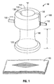
- FIG. 1 is a front perspective view of a surgical apparatus in accordance with the principles of the present disclosure illustrating a seal anchor member positioned relative to the tissue;
- FIG. 2a is a front perspective view of the seal anchor member of FIG. 1 in the maximum folded state
- FIG. 2b is a front perspective view of the seal anchor member of FIG. 1 in an intermediate folded state between the maximum and minimum folded states;
- FIG. 2c is a front perspective view of the seal anchor member of FIG. 1 in the minimum folded state
- FIG. 3 is a front perspective view of the seal anchor member of FIG. 1 illustrating the trailing end of the seal anchor member;
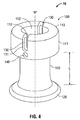
- FIG. 4 is a perspective view of the seal anchor member of FIG. 1 illustrating the slot and the aperture of the trialing end;
- FIG. 5 is a top perspective view of the seal anchor member of FIG. 1 illustrating a plurality of ports extending longitudinally therethrough;
- FIG. 6 is a side cross-sectional view of the seal anchor member of FIG. 1 illustrating a port that extends longitudinally through the leading end and the intermediate portion of the seal anchor member;
- FIG. 9 is a front perspective view of the seal anchor member of FIG. 7 shown in an unfolded state and shown disposed within a tissue tract having first thickness;
- FIG. 10 is a partially cutaway front perspective view of the seal anchor member of FIG. 7 shown in an unfolded state and shown disposed within a tissue tract having a second thickness;
- FIG. 11 is a partially cutaway front perspective view of the seal anchor member of FIG. 7 shown in a folded state and shown disposed within the tissue tract of FIG. 10 ;
- FIG. 12 is a perspective view of the seal anchor member of FIG. 7 shown in an unfolded state and shown disposed within the tissue tract of FIG. 10 ;
- FIG. 13 is a perspective view of the seal anchor member of FIG. 7 illustrated in a folded state and shown disposed within the tissue tract of FIG. 10 ;
- FIG. 15 is a top perspective view of the seal anchor member of FIG. 14 ;
- FIG. 16 is a front prospective view of an a still further embodiment of the seal anchor member.
- FIG. 17 is a top perspective view of the seal anchor member of FIG. 16 .
- proximal or “trailing” refers to the end of the apparatus that is closer to the user and the term “distal” or “leading” refers to the end of the apparatus that is farther from the user.
- distal or “leading” refers to the end of the apparatus that is farther from the user.
- One type of minimal invasive surgery described herein employs a device that facilitates multiple instrument access through a single incision.
- This is a minimally invasive surgical procedure, which permits a user to operate through a single entry point, typically the patient's navel.
- the disclosed procedure involves insufflating the body cavity and positioning a portal member within, e.g., the navel of the patient.
- Instruments including an endoscope and additional instruments such as graspers, staplers, forceps or the like may be introduced within the portal member to carry out the surgical procedure.
- An example of such a surgical portal is disclosed in commonly assigned U.S. patent application Serial No. 12/244,024 , Pub. No. US 2009/0093752 A1, filed October 2, 2008 , the entire content of which is hereby incorporated by reference herein.
- FIG. 1 illustrates a surgical apparatus 10 comprising a seal anchor member 100 in accordance with the principles of the present disclosure.
- Seal anchor member 100 is adapted for insertion within a tissue tract 105, e.g., through the abdominal or peritoneal lining in connection with a laparoscopic surgical procedure. Seal anchor member 100 will be described in greater detail hereinbelow
- seal anchor member 100 defines a longitudinal axis "A" and a length “L” .
- the length “L” describes the distance of the portion of the seal anchor member 100 that can be inserted through the tissue tract 105.
- Seal anchor member 100 has respective trailing and leading ends 110, 120 and an intermediate portion 160 disposed between the trailing and leading ends 110, 120.
- Seal anchor member 100 may be made from a semi-resilient, disposable, compressible, and flexible type material, for example, but not limited to, a suitable foam, gel material, or soft rubber having sufficient compliance to form a seal about one or more surgical objects, and also establish a sealing relation with tissue and with the surgical object.
- the foam includes a polyisoprene material.
- seal anchor member 100 may define a substantially hourglass shape. However, it is contemplated that the seal anchor member 100 may define other configurations both prior and subsequent to insertion within tissue.
- trailing end 110 is configured to fold at any position along the longitudinal axis thus resulting in various seal anchor member lengths.
- trailing end 110 is configured to define a plurality of folded states. Each of the three folded states in FIGS. 2a - 2c corresponds to a different length of seal anchor member 100: "L1", “L2" and "L3". Trailing end 110 in each folded state defines an outer surface 111 and an inner surface 112.
- the outer surface 111 is formed by the portion of the trailing end 110 that is folded along the longitudinal axis "A" , whereas the inner surface 112 is formed by the portion of the trailing end 110 that is not yet folded. As the trailing end 110 transits among different folded states, portions of the outer surface 111 may gradually merge into the inner surface 112, and vice versa.
- the plurality of the folded states range between a maximum folded state as shown in FIG. 2a and a minimum folded state as shown in FIG. 2c .
- the maximum folded state describes a state in which a maximum portion of the trailing end 110 is folded. Accordingly, the length "L" of seal anchor member 100 is minimized, thus resulting in a minimum length "L” of seal anchor member 100.
- the minimum folded state happens when a minimum portion of the trailing end 110 is folded, resulting in a maximum length "L” of seal anchor member 100.
- seal anchor member 100 can be configured to different lengths, and it can be adapted to different tissue thicknesses.
- each slot 130 spans across the outer surface 111 and the inner surface 112 of the trialing end 110.
- the two slots 130 are diametrically opposed on the trailing end 110.
- each slot 130 corresponds to an aperture 140 which is defined by the trailing end 110.
- Each aperture 140 is positioned directly beneath its corresponding slot 130 on the outer surface 111 of the trailing end 110.
- each slot 130 further corresponds to a pin 150 which is disposed through the outer surface 111 and the inner surface 112 of the trailing end 110.
- Each pin 150 includes a head 151, a body 152, and a handle 153.
- the pin 150 is disposed through the outer surface 111 by having its body 152 positioned through the aperture 140 which is defined beneath the pin's 150 corresponding slot 130.
- the body 152 is attached firmly to the outer surface 111 of the trailing end 110. Further, the pin 150 protrudes beyond the outer surface and forms the handle 153 which can be used by a surgeon to adjust the position of pin 150 along the longitudinal axis "A.” Further, the pin 150 extends through its corresponding slot 130 defined on the inner surface 112. The portion of the pin 150 that extends beyond the inner surface 112 forms the head 151 of pin 150.
- the head 151 has a diameter greater than that of the body 152. The head 151 is placed against the inner surface 112 of the trialing end 110.
- the pin 150 is configured to slide through the slot 130 by lifting the handle 153 up and down along the longitudinal axis "A."
- the slot 130 provides a passageway that guides the pin 150 to slide longitudinally under the control of the handle 153.
- the trailing end 110 undergoes a transition between the maximum folded state and the minimum folded state. Accordingly, the seal anchor member 100 transits between the minimum length "L” and the maximum length "L". Further details regarding this transition are explained below.
- Seal anchor member 200 includes a leading end 120, an intermediate portion 160, and a trailing end 210.
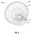
- a plurality of ports 170 is disposed between the intermediate portion 160 and the leading end 120 as illustrated in FIG. 8 .
- the trailing end 210 has an unfolded state in which the trailing end 210 is fully unfurled.
- the seal anchor member 200 reaches its maximum length "L” when the trailing end 210 is in the unfolded state.
- the leading end 120 defines a radial diameter "D1" relatively smaller than a radial diameter "D2" defined by the trailing end 210.
- the leading end 120 with its relatively small dimension provides easy insertion and removal of the seal anchor member 200 through skin tissues, thus, reducing the time required to place and/or displace the seal anchor member 200 through the incisions during surgical operations and reducing tissue trauma.
- the trailing end 210 with its relatively large dimension creates a wide open space above the plurality of ports 170. As a result, the trailing end 210 provides the surgeon a large free space to manipulate portions of the surgical instruments positioned above the ports 170, ultimately resulting in a significantly increased range of motion of the surgical instruments inserted through the seal anchor member 200 and facilitating off-axis motions of the surgical instruments.
- the relatively large trailing end 210 also facilitates transition among the plurality of the folded states as well as the unfolded state.
- tissue tract 105 has a thickness T1 that corresponds to the overall length of seal anchor member 200 in an unfolded state.
- the seal anchor member 200 need not be folded.
- T2 thickness T2 ( FIGS. 10-13 )
- adjustment of the overall length of the seal anchor member 200 may be made to approximate thickness T2, as is illustrated in FIGS. 11 and 13 .
- the surgical apparatus exhibits a coring configuration as illustrated in FIG. 10 , wherein the trailing end 210 and the intermediate portion 160 define a large free, open space in the center region of the seal anchor member 200 as if a large amount of materials has been removed therefrom.
- the intermediate portion 160 is filled with only a small amount of materials within the region "B" adjacent to the leading end 120, as indicated in FIG. 10 , for defining the port 170. Therefore, the port 170 in this particular embodiment is relatively small along the longitudinal axis "A.”
- the coring configuration increases the flexibility of the seal anchor member 200 such that the overall shape of the seal anchor member 200 can be easily manipulated.
- the seal anchor member defines a substantially large length, such that the intermediate portion of the surgical apparatus is substantially lengthy along the longitudinal axis "A" of the seal anchor member between the trailing and leading ends.
- the seal anchor member further includes at least one longitudinal port substantially lengthy along the longitudinal axis "A” thereof between the intermediate portion and the leading end or between the trailing end and the leading end.
- the surgical apparatus of this embodiment is particularly designed to accommodate unusually thick tissues for purposes to be used in bariatric related treatment procedures. Obese patients have significantly thick tissues compared to patients of normal weight. During bariatric related treatment procedures, an incision is initially created off the midline for providing an access to the patient's body cavity.
- Access devices taught by the prior art are oftentimes not tall enough to be placed across the entire abdominal walls of obese patients.
- the prior access device cannot be securely placed within incisions, thereby adversely influencing the operation of bariatric procedures.
- the seal anchor member with a substantial length solves this problem.
- the seal anchor member can be securely placed at the incision extending across a very thick abdominal wall for introducing surgical instruments therethrough to manipulate tissues or organs within the body cavity.
- the seal anchor member is securely fit with respect to the incision, resulting in a stable state facilitating introduction of surgical instruments therethrough for performing bariatric procedures.
- a surgical apparatus 30 includes a seal anchor member 300 including a leading end 120, a trailing end 210, an inner surface 112, an outer surface 111, and a suture 180 adapted to maintain a selected folded state.
- suture 180 may be used to connect the inner surface 112 and the outer surface 111 of the trailing end 110 together for purposes of maintaining the selected folded state.
- a surgical apparatus 40 includes a seal anchor member 400.
- Seal anchor member 400 exhibits an elongated hourglass configuration and is substantially symmetrical with respect to radial axis "R.”
- a plurality of ports 170 is disposed within the seal anchor member 400 and are arranged in a linear fashion along radial axis "R," each port 170 including a lumen that is substantially parallel to longitudinal axis "A" of the seal anchor member 400.
- the ports 170 may be equidistantly spaced apart.
- the seal anchor member may define a coring configuration having a substantial length for accommodating thick abdominal walls, and may comprise four longitudinal ports.
- the seal anchor member may define a coring configuration having a substantial length for accommodating thick abdominal walls, and may further comprise a relatively small leading end, a relatively large trailing end and four longitudinal ports extending therethrough. Any of the presently disclosed embodiments may be used in procedures where access is achieved through a naturally occurring orifice (e.g. vagina or anus).
Abstract
A surgical apparatus for positioning within a tissue tract accessing an underlying body cavity is adapted to tissues having different thicknesses. The surgical apparatus is configured to have different lengths. In one embodiment, the surgical includes a seal anchor member having two ends, one of which can be configured to fold and result in a plurality of folded states. Each folded state corresponds to a different length of the seal anchor member. The seal anchor member includes a slot to facilitate transition within the plurality of folded states. The seal anchor member further includes an aperture and a pin configured to further facilitate transition within the plurality of folded states.
Description
- This application claims priority to, and the benefit of,
U.S. Provisional Patent Application Serial Number 61/323,013, filed on April 12, 2010 - The present disclosure relates generally to surgical apparatuses for use in minimally invasive surgical procedures, such as endoscopic and/or laparoscopic procedures, and more particularly, relates to a surgical apparatus that allows multiple surgical instruments to be inserted through a single incision.
- Today, many surgical procedures are performed through small incisions in the skin, as compared to the larger incisions typically required in traditional procedures, in an effort to reduce both trauma to the patient and recovery time. Generally, such procedures are referred to as "endoscopic", unless performed on the patient's abdomen, in which case the procedure is referred to as "laparoscopic." Throughout the present disclosure, the term "minimally invasive" should be understood to encompass both endoscopic and laparoscopic procedures.
- During a typical minimally invasive procedure, surgical objects, such as surgical access devices (e.g., trocar and cannula assemblies) or endoscopes, are inserted into the patient's body through the incision in tissue. In general, prior to the introduction of the surgical object into the patient's body, insufflation gas is used to enlarge the area surrounding the target surgical site to create a larger, more accessible work area. Accordingly, the maintenance of a substantially fluid-tight seal is desirable so as to inhibit the escape of the insufflation gas and the deflation or collapse of the enlarged surgical site.
- Different patients have different tissue thicknesses. Generally, access devices of different lengths are supplied in order to meet the various demands of patients based on their various tissue thicknesses. Such prior access devices as have been heretofore provided have had numerous disadvantages both from the standpoint of design as well as from the standpoint of availability of use.
- From the design perspective, no one single prior access device is universally suitable for tissues having different thicknesses. In the prior art, each access device is designed in contemplation of a tissue having a particular thickness. Thus, access devices of different lengths have to be designed and supplied in order to accommodate patients with different needs based on their tissue thicknesses.
- In the use of prior access devices, patient's tissue thickness needs to be assessed before performing a minimally invasive procedure. After assessing the tissue thickness and before performing the procedure, an access device having a length suitable for the patient's tissue thickness is selected. An error made in the assessment may lead to consequences adversely impacting the procedure. For instance, if the assessment underestimates the patent's tissue thickness, then an access device having a length less than the patient's tissue thickness may be selected. As a result, the selected access device is inadequate for the procedure, thus delaying the performance of the procedure.
- Thus, to avoid the need of designing and supplying access devices of different lengths, to preclude the need of assessing tissue thickness, and to avoid unnecessary problems caused by the assessment, it is desirable to have a single access device that can be configured to different lengths, such that the single access device can be suitable for tissues having different thicknesses.
- Disclosed herein is a surgical apparatus for positioning within a tissue tract accessing an underlying body cavity. The surgical apparatus comprises a seal anchor member. The seal anchor member has a longitudinal axis, a length, a first end and a second end. The first end is configured to fold along the longitudinal axis, resulting in a plurality of states. Each state corresponds to a different length of the seal anchor member.
- In one embodiment, the plurality of states comprises a plurality of folded states. In each folded state, the first end has an outer surface and an inner surface. Each folded state is maintained by connecting the outer surface and the inner surface of the first end together. The plurality of folded states includes a maximum folded state and a minimum folded state. In the maximum folded state, the length of the seal anchor member is minimized. Likewise, in the minimum folded state, the length of the seal anchor member is maximized.
- In another embodiment, the plurality of states further comprises an unfolded state in which the first end of the seal anchor member is not folded. Similar to the embodiment described above, the length of the seal anchor is minimized in the maximum folded state. Unlike the embodiment described above, the length of the seal anchor member is maximized in the unfolded state.
- In a certain embodiment, the first end of the seal anchor member defines a slot to facilitate transition among the plurality of folded states. Further, the first end defines an aperture through which a pin is used to further facilitate transition between the maximum and minimum folded states. The pin further connects the outer surface and the inner surface together to maintain a folded state.
- In another embodiment, a surgeon manually adjusts the length of the outer surface and the length of the inner surface of the first end in order to select a desired folded state. After making the selection, the surgeon uses a suture to hold the inner surface and the outer surface of the first end together for purposes of maintaining the selected folded state.
- In a certain embodiment, the first end defines a substantially large radial diameter thereby increasing the range of motion of the surgical instruments inserted through the seal anchor member. The second end defines a substantially small radial diameter thereby providing easy insertion and removal of the seal anchor member through the tissues.
- In a further embodiment, the length of the seal anchor member is substantially large for accommodating thick tissues in bariatric related procedures.
- In another embodiment, the seal anchor member defines a coring configuration such that there is a large free open space within the seal anchor member for providing a large range of motion of the surgical instruments inserted therethrough.
- In a preferred embodiment, the seal anchor member defines at least four longitudinal ports extending therethrough for accommodating surgical instruments.
- The above and other aspects, features, and advantages of the present disclosure will become more apparent in light of the following detailed description when taken in conjunction with the accompanying drawings in which:
-
FIG. 1 is a front perspective view of a surgical apparatus in accordance with the principles of the present disclosure illustrating a seal anchor member positioned relative to the tissue; -
FIG. 2a is a front perspective view of the seal anchor member ofFIG. 1 in the maximum folded state; -
FIG. 2b is a front perspective view of the seal anchor member ofFIG. 1 in an intermediate folded state between the maximum and minimum folded states; -
FIG. 2c is a front perspective view of the seal anchor member ofFIG. 1 in the minimum folded state; -
FIG. 3 is a front perspective view of the seal anchor member ofFIG. 1 illustrating the trailing end of the seal anchor member; -
FIG. 4 is a perspective view of the seal anchor member ofFIG. 1 illustrating the slot and the aperture of the trialing end; -
FIG. 5 is a top perspective view of the seal anchor member ofFIG. 1 illustrating a plurality of ports extending longitudinally therethrough; -
FIG. 6 is a side cross-sectional view of the seal anchor member ofFIG. 1 illustrating a port that extends longitudinally through the leading end and the intermediate portion of the seal anchor member; -
FIG. 7 is a front prospective view of an alternate embodiment of the seal anchor member shown in an unfolded state; -
FIG. 8 is a top prospective view of the seal anchor member ofFIG. 7 ; -
FIG. 9 is a front perspective view of the seal anchor member ofFIG. 7 shown in an unfolded state and shown disposed within a tissue tract having first thickness; -
FIG. 10 is a partially cutaway front perspective view of the seal anchor member ofFIG. 7 shown in an unfolded state and shown disposed within a tissue tract having a second thickness; -
FIG. 11 is a partially cutaway front perspective view of the seal anchor member ofFIG. 7 shown in a folded state and shown disposed within the tissue tract ofFIG. 10 ; -
FIG. 12 is a perspective view of the seal anchor member ofFIG. 7 shown in an unfolded state and shown disposed within the tissue tract ofFIG. 10 ; -
FIG. 13 is a perspective view of the seal anchor member ofFIG. 7 illustrated in a folded state and shown disposed within the tissue tract ofFIG. 10 ; -
FIG. 14 is a front prospective view yet another embodiment of a seal anchor member shown positioned relative to the tissue; -
FIG. 15 is a top perspective view of the seal anchor member ofFIG. 14 ; -
FIG. 16 is a front prospective view of an a still further embodiment of the seal anchor member; and -
FIG. 17 is a top perspective view of the seal anchor member ofFIG. 16 . - Particular embodiments of the present disclosure will be described herein with reference to the accompanying drawings. As shown in the drawings and as described throughout the following description, and as is traditional when referring to relative positioning on an object, the term "proximal" or "trailing" refers to the end of the apparatus that is closer to the user and the term "distal" or "leading" refers to the end of the apparatus that is farther from the user. In the following description, well-known functions or constructions are not described in detail to avoid obscuring the present disclosure in unnecessary detail.
- One type of minimal invasive surgery described herein employs a device that facilitates multiple instrument access through a single incision. This is a minimally invasive surgical procedure, which permits a user to operate through a single entry point, typically the patient's navel. The disclosed procedure involves insufflating the body cavity and positioning a portal member within, e.g., the navel of the patient. Instruments including an endoscope and additional instruments such as graspers, staplers, forceps or the like may be introduced within the portal member to carry out the surgical procedure. An example of such a surgical portal is disclosed in commonly assigned
U.S. patent application Serial No. 12/244,024 , Pub. No.US 2009/0093752 A1, filed October 2, 2008 , the entire content of which is hereby incorporated by reference herein. - Referring now to the drawings, in which like reference numerals identify identical or substantially similar parts throughout the several views,
FIG. 1 illustrates asurgical apparatus 10 comprising aseal anchor member 100 in accordance with the principles of the present disclosure.Seal anchor member 100 is adapted for insertion within atissue tract 105, e.g., through the abdominal or peritoneal lining in connection with a laparoscopic surgical procedure.Seal anchor member 100 will be described in greater detail hereinbelow - With reference to
FIG. 1 ,seal anchor member 100 defines a longitudinal axis "A" and a length "L". The length "L" describes the distance of the portion of theseal anchor member 100 that can be inserted through thetissue tract 105.Seal anchor member 100 has respective trailing and leading ends 110, 120 and anintermediate portion 160 disposed between the trailing and leading ends 110, 120.Seal anchor member 100 may be made from a semi-resilient, disposable, compressible, and flexible type material, for example, but not limited to, a suitable foam, gel material, or soft rubber having sufficient compliance to form a seal about one or more surgical objects, and also establish a sealing relation with tissue and with the surgical object. In one embodiment, the foam includes a polyisoprene material. As shown inFIG. 1 ,seal anchor member 100 may define a substantially hourglass shape. However, it is contemplated that theseal anchor member 100 may define other configurations both prior and subsequent to insertion within tissue. - Due to the flexible and semi-resilient characteristics of
seal anchor member 100, the length "L" ofseal anchor member 100 can be adjusted to be suitable for tissues of different thicknesses. In one embodiment, as illustrated inFIG. 1 , to configureseal anchor member 100 to have different lengths, trailingend 110 is configured to fold at any position along the longitudinal axis thus resulting in various seal anchor member lengths. As best illustrated inFIGS. 2a - 2c , trailingend 110 is configured to define a plurality of folded states. Each of the three folded states inFIGS. 2a - 2c corresponds to a different length of seal anchor member 100: "L1", "L2" and "L3". Trailingend 110 in each folded state defines anouter surface 111 and aninner surface 112. Theouter surface 111 is formed by the portion of the trailingend 110 that is folded along the longitudinal axis "A", whereas theinner surface 112 is formed by the portion of the trailingend 110 that is not yet folded. As the trailingend 110 transits among different folded states, portions of theouter surface 111 may gradually merge into theinner surface 112, and vice versa. - The plurality of the folded states range between a maximum folded state as shown in
FIG. 2a and a minimum folded state as shown inFIG. 2c . The maximum folded state describes a state in which a maximum portion of the trailingend 110 is folded. Accordingly, the length "L" ofseal anchor member 100 is minimized, thus resulting in a minimum length "L" ofseal anchor member 100. In contrast, the minimum folded state happens when a minimum portion of the trailingend 110 is folded, resulting in a maximum length "L" ofseal anchor member 100. Thus,seal anchor member 100 can be configured to different lengths, and it can be adapted to different tissue thicknesses. - To facilitate transition between the maximum and minimum folded state, the trailing
end 110 defines twoslots 130, as illustrated inFIG. 3 . Eachslot 130 spans across theouter surface 111 and theinner surface 112 of the trialingend 110. The twoslots 130 are diametrically opposed on the trailingend 110. As illustrated inFIG. 4 , eachslot 130 corresponds to anaperture 140 which is defined by the trailingend 110. Eachaperture 140 is positioned directly beneath itscorresponding slot 130 on theouter surface 111 of the trailingend 110. With reference toFIG. 5 , eachslot 130 further corresponds to apin 150 which is disposed through theouter surface 111 and theinner surface 112 of the trailingend 110. Eachpin 150 includes ahead 151, abody 152, and ahandle 153. Thepin 150 is disposed through theouter surface 111 by having itsbody 152 positioned through theaperture 140 which is defined beneath the pin's 150corresponding slot 130. Thebody 152 is attached firmly to theouter surface 111 of the trailingend 110. Further, thepin 150 protrudes beyond the outer surface and forms thehandle 153 which can be used by a surgeon to adjust the position ofpin 150 along the longitudinal axis "A." Further, thepin 150 extends through itscorresponding slot 130 defined on theinner surface 112. The portion of thepin 150 that extends beyond theinner surface 112 forms thehead 151 ofpin 150. Thehead 151 has a diameter greater than that of thebody 152. Thehead 151 is placed against theinner surface 112 of the trialingend 110. - With continued reference to
FIG. 5 , thepin 150 is configured to slide through theslot 130 by lifting thehandle 153 up and down along the longitudinal axis "A." Essentially, theslot 130 provides a passageway that guides thepin 150 to slide longitudinally under the control of thehandle 153. As thepin 150 slides from one end of theslot 130 to the other end of theslot 130, the trailingend 110 undergoes a transition between the maximum folded state and the minimum folded state. Accordingly, theseal anchor member 100 transits between the minimum length "L" and the maximum length "L". Further details regarding this transition are explained below. - With reference to
FIGS. 2a-2c , as thehandle 153 is lifted in an upward direction along the longitudinal axis "A", portions of theouter surface 111 gradually merge into theinner surface 112, thus, transiting the trailingend 111 from a more folded state, as shown inFIG. 2a , to a less folded state, as shown inFIG. 2c , thereby increasing the length "L" of theseal anchor member 100. In contrast, as thehandle 153 is pushed in a downward direction along the longitudinal axis "A", portions of theinner surface 112 gradually merge into theouter surface 111, thus, transiting the trailing end from a less folded state, shown inFIG. 2c , to a more folded state, as shown inFIG. 2a , thereby decreasing the length "L" of theseal anchor member 100. Thus, the user can adjust the length "L" of theseal anchor member 100 by adjusting thehandle 153 along the longitudinal axis "A" until a desired length is reached. - With reference to
FIGS. 5 and 6 , the trailingend 110 exhibits an elongated, tubular structure defining a hollow center region, as shown inFIG. 6 .Seal anchor member 100 further includes at least onlongitudinal port 170 extending along the longitudinal axis "A" ofseal anchor member 100 between theleading end 120 and theintermediate portion 160. Theports 170 are configured symmetrically with respect to the longitudinal axis "A". Theports 170 are spaced equidistant from the longitudinal axis "A". Eachport 170 may be spaced equidistant from its neighboring ports. Thelongitudinal ports 170 are dimensioned to receive a surgical object, e.g. a surgical instrument (not shown) therethrough. Upon introduction of an instrument or surgical object (not shown) through arespective port 170, the inner surface portions defining theport 170 establish and maintain a substantial sealed relation about the instrument or surgical object. - Turning now to
FIGS. 7-13 , asurgical apparatus 20 including aseal anchor member 200 will now be described.Seal anchor member 200 includes aleading end 120, anintermediate portion 160, and a trailingend 210. A plurality ofports 170 is disposed between theintermediate portion 160 and theleading end 120 as illustrated inFIG. 8 . As illustrated inFIG. 7 , the trailingend 210 has an unfolded state in which the trailingend 210 is fully unfurled. Theseal anchor member 200 reaches its maximum length "L" when the trailingend 210 is in the unfolded state. Theleading end 120 defines a radial diameter "D1" relatively smaller than a radial diameter "D2" defined by the trailingend 210. This particular configuration of theseal anchor member 200 with one end substantially small and the other end substantially large provides many benefits to surgical procedures. Theleading end 120 with its relatively small dimension provides easy insertion and removal of theseal anchor member 200 through skin tissues, thus, reducing the time required to place and/or displace theseal anchor member 200 through the incisions during surgical operations and reducing tissue trauma. The trailingend 210 with its relatively large dimension creates a wide open space above the plurality ofports 170. As a result, the trailingend 210 provides the surgeon a large free space to manipulate portions of the surgical instruments positioned above theports 170, ultimately resulting in a significantly increased range of motion of the surgical instruments inserted through theseal anchor member 200 and facilitating off-axis motions of the surgical instruments. The relatively large trailingend 210 also facilitates transition among the plurality of the folded states as well as the unfolded state. - As shown in
FIGS. 9-13 , adjustment of the length of theseal anchor member 200 to accommodatetissue tracts 105 having different thicknesses. As seen inFIG. 9 ,tissue tract 105 has a thickness T1 that corresponds to the overall length ofseal anchor member 200 in an unfolded state. In such a situation, where the thickness of thetissue tract 105 corresponds to the unfolded length of theseal anchor member 200, theseal anchor member 200 need not be folded. However, in situations in which thetissue tract 105 has a thickness, e.g., thickness T2 (FIGS. 10-13 ), that is less than the unfolded length of theseal anchor member 200, adjustment of the overall length of theseal anchor member 200 may be made to approximate thickness T2, as is illustrated inFIGS. 11 and13 . As illustrated inFIGS. 11 and13 , the trailingend 210 is folded such that the trailingend 210 is moved towards the surface of thetissue tract 105, thereby reducing the distance between trailing and leading ends 210, 120 and substantially approximating thickness T2. - In a preferred embodiment, the surgical apparatus exhibits a coring configuration as illustrated in
FIG. 10 , wherein the trailingend 210 and theintermediate portion 160 define a large free, open space in the center region of theseal anchor member 200 as if a large amount of materials has been removed therefrom. Theintermediate portion 160 is filled with only a small amount of materials within the region "B" adjacent to theleading end 120, as indicated inFIG. 10 , for defining theport 170. Therefore, theport 170 in this particular embodiment is relatively small along the longitudinal axis "A." The coring configuration increases the flexibility of theseal anchor member 200 such that the overall shape of theseal anchor member 200 can be easily manipulated. For instance, due to the large empty space within theseal anchor member 200, theseal anchor member 200 can be easily squeezed to facilitate its insertion through incisions. Since theseal anchor member 200 can be easily reduced to a small dimension due to squeezing, the incision through which theseal anchor member 200 to be placed can be created to have a relatively small opening thereby reducing the trauma experienced by the patients and subsequently reducing the patients' recovery time required to heal the incision. Further, the large free space defined above theport 170 increases the maneuverability and the range of motion of the surgical instruments inserted through theseal anchor member 200 and also significantly facilitates off-axis motions of the surgical instruments. - In a certain embodiment, the seal anchor member defines a substantially large length, such that the intermediate portion of the surgical apparatus is substantially lengthy along the longitudinal axis "A" of the seal anchor member between the trailing and leading ends. The seal anchor member further includes at least one longitudinal port substantially lengthy along the longitudinal axis "A" thereof between the intermediate portion and the leading end or between the trailing end and the leading end. The surgical apparatus of this embodiment is particularly designed to accommodate unusually thick tissues for purposes to be used in bariatric related treatment procedures. Obese patients have significantly thick tissues compared to patients of normal weight. During bariatric related treatment procedures, an incision is initially created off the midline for providing an access to the patient's body cavity. Access devices taught by the prior art are oftentimes not tall enough to be placed across the entire abdominal walls of obese patients. Thus, the prior access device cannot be securely placed within incisions, thereby adversely influencing the operation of bariatric procedures. The seal anchor member with a substantial length solves this problem. The seal anchor member can be securely placed at the incision extending across a very thick abdominal wall for introducing surgical instruments therethrough to manipulate tissues or organs within the body cavity. Thus, the seal anchor member is securely fit with respect to the incision, resulting in a stable state facilitating introduction of surgical instruments therethrough for performing bariatric procedures.
- In a preferred embodiment, the seal anchor member defines at least four
ports 170, with at least one port for accommodating an instrument connected to an insufflation or evacuation source. - In a further embodiment, as illustrated in
FIGS. 14 and15 , asurgical apparatus 30 includes aseal anchor member 300 including aleading end 120, a trailingend 210, aninner surface 112, anouter surface 111, and asuture 180 adapted to maintain a selected folded state. Upon folding the trailingend 210 to achieve a desired folded state,suture 180 may be used to connect theinner surface 112 and theouter surface 111 of the trailingend 110 together for purposes of maintaining the selected folded state. - In a still further embodiment, as illustrated in
FIGS. 16 and17 , asurgical apparatus 40 includes aseal anchor member 400.Seal anchor member 400 exhibits an elongated hourglass configuration and is substantially symmetrical with respect to radial axis "R." A plurality ofports 170 is disposed within theseal anchor member 400 and are arranged in a linear fashion along radial axis "R," eachport 170 including a lumen that is substantially parallel to longitudinal axis "A" of theseal anchor member 400. Theports 170 may be equidistantly spaced apart. - Different embodiments of the disclosure may be combined with one another based on the particular needs of the patients to achieve optimal results of the surgical procedures. In one example, in bariatric related procedures, the seal anchor member may define a coring configuration having a substantial length for accommodating thick abdominal walls, and may comprise four longitudinal ports. In another example associated with bariatric related procedures, the seal anchor member may define a coring configuration having a substantial length for accommodating thick abdominal walls, and may further comprise a relatively small leading end, a relatively large trailing end and four longitudinal ports extending therethrough. Any of the presently disclosed embodiments may be used in procedures where access is achieved through a naturally occurring orifice (e.g. vagina or anus).
- While several embodiments of the disclosure have been shown in the drawings and/or discussed herein, it is not intended that the disclosure be limited thereto, as it is intended that the disclosure be as broad in scope as the art will allow and that the specification be read likewise. Therefore, the above description should not be construed as limiting, but merely as exemplifications of particular embodiments. Those skilled in the art will envision other modifications within the scope and spirit of the claims appended hereto.
- The invention may be described by reference to the following numbered paragaphs:
- 1. A surgical apparatus for positioning within a tissue tract accessing an underlying body cavity, which comprises:
- a seal anchor member defining a longitudinal axis and a length, the seal anchor member including a first end and a second end, the first end configured to fold along the longitudinal axis, the first end defining a plurality of states, each state corresponding to a different length of the seal anchor member.
- 2. The surgical apparatus according to paragraph 1 wherein the plurality of states comprise a plurality of folded states.
- 3. The surgical apparatus according to paragraph 2 wherein the plurality of folded states include a maximum folded state such that the maximum folded state corresponds to a minimum length of the seal anchor member.
- 4. The surgical apparatus according to paragraph 2 wherein the plurality of folded states include a minimum folded state such that the minimum folded state corresponds to a maximum length of the seal anchor member.
- 5. The surgical apparatus according to paragraph 2 wherein each folded state has an outer surface and an inner surface of the first end.
- 6. The surgical apparatus according to paragraph 5 wherein each folded state is maintained by connecting the outer surface and the inner surface of the first end.
- 7. The surgical apparatus according to paragraph 2 wherein the first end defines a slot configured to facilitate transition within the plurality of folded states.
- 8. The surgical apparatus according to paragraph 2 wherein the first end defines an aperture through which a pin is configured to facilitate transition within the plurality of folded states.
- 9. The surgical apparatus according to paragraph 1 wherein the plurality of states comprise an unfolded state, wherein the unfolded state corresponds to a maximum length of the seal anchor member.
- 10. The surgical apparatus according to paragraph 1 further comprising an intermediate portion disposed between the first and second ends along the longitudinal axis.
- 11. The surgical apparatus according to
paragraph 10 further comprising at least one longitudinal port extending between the intermediate portion and the second end and being configured for substantially sealed reception of an object therein. - 12. The surgical apparatus according to paragraph 11 wherein the at least one longitudinal port is configured symmetrically with respect to the longitudinal axis.
- 13. The surgical apparatus according to paragraph 11 wherein the at least one longitudinal port is arranged in a linear fashion along a radial axis of the seal anchor member.
- 14. The surgical apparatus according to paragraph 1 wherein the trailing end exhibits a tubular configuration.
- 15. The surgical apparatus according to paragraph 1 wherein the seal anchor member exhibits an hourglass configuration.
- 16. The surgical apparatus according to paragraph 1 wherein the seal anchor member exhibits an hourglass configuration elongated in a radial axis of the seal anchor member.
Claims (16)
- A surgical apparatus for positioning within a tissue tract accessing an underlying body cavity, which comprises:a seal anchor member defining a longitudinal axis and a length, the seal anchor member including a first end and a second end, the first end configured to fold along the longitudinal axis, the first end defining a plurality of states, each state corresponding to a different length of the seal anchor member.
- The surgical apparatus according to claim 1 wherein the plurality of states comprise a plurality of folded states.
- The surgical apparatus according to claim 2 wherein the plurality of folded states include a maximum folded state such that the maximum folded state corresponds to a minimum length of the seal anchor member.
- The surgical apparatus according to claim 2 wherein the plurality of folded states include a minimum folded state such that the minimum folded state corresponds to a maximum length of the seal anchor member.
- The surgical apparatus according to any of claims 2 to 4 wherein each folded state has an outer surface and an inner surface of the first end.
- The surgical apparatus according to claim 5 wherein each folded state is maintained by connecting the outer surface and the inner surface of the first end.
- The surgical apparatus according to any preceding claim wherein the first end defines a slot configured to facilitate transition within the plurality of folded states.
- The surgical apparatus according to any of claims 1 to 6 wherein the first end defines an aperture through which a pin is configured to facilitate transition within the plurality of folded states.
- The surgical apparatus according to claim 1 wherein the plurality of states comprise an unfolded state, wherein the unfolded state corresponds to a maximum length of the seal anchor member.
- The surgical apparatus according to any preceding claim further comprising an intermediate portion disposed between the first and second ends along the longitudinal axis.
- The surgical apparatus according to claim 10 further comprising at least one longitudinal port extending between the intermediate portion and the second end and being configured for substantially sealed reception of an object therein.
- The surgical apparatus according to claim 11 wherein the at least one longitudinal port is configured symmetrically with respect to the longitudinal axis.
- The surgical apparatus according to claim 11 wherein the at least one longitudinal port is arranged in a linear fashion along a radial axis of the seal anchor member.
- The surgical apparatus according to any preceding claim wherein the trailing end exhibits a tubular configuration.
- The surgical apparatus according to any preceding claim wherein the seal anchor member exhibits an hourglass configuration.
- The surgical apparatus according to claim 15 wherein the seal anchor member exhibits an hourglass configuration elongated in a radial axis of the seal anchor member.
Applications Claiming Priority (2)
| Application Number | Priority Date | Filing Date | Title |
|---|---|---|---|
| US32301310P | 2010-04-12 | 2010-04-12 | |
| US13/031,346 US20110251463A1 (en) | 2010-04-12 | 2011-02-21 | Bariatric foam port |
Publications (1)
| Publication Number | Publication Date |
|---|---|
| EP2374423A1 true EP2374423A1 (en) | 2011-10-12 |
Family
ID=44246113
Family Applications (1)
| Application Number | Title | Priority Date | Filing Date |
|---|---|---|---|
| EP11250456A Withdrawn EP2374423A1 (en) | 2010-04-12 | 2011-04-11 | Universal height access port |
Country Status (5)
| Country | Link |
|---|---|
| US (1) | US20110251463A1 (en) |
| EP (1) | EP2374423A1 (en) |
| JP (1) | JP2011218174A (en) |
| AU (1) | AU2011201068A1 (en) |
| CA (1) | CA2734025A1 (en) |
Cited By (1)
| Publication number | Priority date | Publication date | Assignee | Title |
|---|---|---|---|---|
| EP2617373A1 (en) * | 2012-01-19 | 2013-07-24 | Covidien LP | Access port having rollable proximal end |
Families Citing this family (44)
| Publication number | Priority date | Publication date | Assignee | Title |
|---|---|---|---|---|
| US20090093752A1 (en) | 2007-10-05 | 2009-04-09 | Tyco Healthcare Group Lp | Seal anchor for use in surgical procedures |
| USD738500S1 (en) | 2008-10-02 | 2015-09-08 | Covidien Lp | Seal anchor for use in surgical procedures |
| US8585632B2 (en) * | 2009-07-31 | 2013-11-19 | Covidien LLP | Single port device having integral filter/vent |
| US8684918B2 (en) | 2009-10-02 | 2014-04-01 | Covidien Lp | Single port device including selectively closeable openings |
| US8920314B2 (en) | 2009-10-07 | 2014-12-30 | Covidien Lp | Universal height foam port |
| US8821390B2 (en) | 2010-04-12 | 2014-09-02 | Covidien Lp | Surgical access method and assembly including sleeve and port |
| US9421032B2 (en) * | 2010-06-16 | 2016-08-23 | Covidien Lp | Seal port with blood collector |
| US8668642B2 (en) * | 2010-11-23 | 2014-03-11 | Covidien Lp | Port device including retractable endoscope cleaner |
| US8727973B2 (en) | 2010-11-23 | 2014-05-20 | Covidien Lp | Seal port with adjustable height |
| US9119664B2 (en) | 2010-12-20 | 2015-09-01 | Covidien Lp | Integral foam port |
| US9549758B2 (en) * | 2011-03-23 | 2017-01-24 | Covidien Lp | Surgical access assembly with adapter |
| US9119666B2 (en) * | 2011-03-25 | 2015-09-01 | Covidien Lp | Access port with integrated flexible sleeve |
| US8845529B2 (en) | 2011-12-29 | 2014-09-30 | Covidien Lp | Surgical access assembly and method of use therefor |
| US9017249B2 (en) * | 2012-03-26 | 2015-04-28 | Covidien Lp | Surgical access assembly and method of use therefor |
| US20140051934A1 (en) * | 2012-08-16 | 2014-02-20 | Covidien Lp | Stabilizing Port for Surgery for Facilitating Concurrent Introduction of Multiple Instruments |
| JP6302467B2 (en) * | 2013-05-31 | 2018-03-28 | 利昭 森川 | Thoracoscopic trocar and thoracoscopic port instrumentation kit |
| US10064649B2 (en) | 2014-07-07 | 2018-09-04 | Covidien Lp | Pleated seal for surgical hand or instrument access |
| US9707011B2 (en) | 2014-11-12 | 2017-07-18 | Covidien Lp | Attachments for use with a surgical access device |
| US11160682B2 (en) | 2017-06-19 | 2021-11-02 | Covidien Lp | Method and apparatus for accessing matter disposed within an internal body vessel |
| US10828065B2 (en) | 2017-08-28 | 2020-11-10 | Covidien Lp | Surgical access system |
| US10675056B2 (en) | 2017-09-07 | 2020-06-09 | Covidien Lp | Access apparatus with integrated fluid connector and control valve |
| US11389193B2 (en) | 2018-10-02 | 2022-07-19 | Covidien Lp | Surgical access device with fascial closure system |
| US11457949B2 (en) | 2018-10-12 | 2022-10-04 | Covidien Lp | Surgical access device and seal guard for use therewith |
| US10932767B2 (en) | 2018-12-07 | 2021-03-02 | Covidien Lp | Surgical access assembly and method of use therefor |
| US10792071B2 (en) | 2019-02-11 | 2020-10-06 | Covidien Lp | Seals for surgical access assemblies |
| US11166748B2 (en) | 2019-02-11 | 2021-11-09 | Covidien Lp | Seal assemblies for surgical access assemblies |
| US11000313B2 (en) | 2019-04-25 | 2021-05-11 | Covidien Lp | Seals for surgical access devices |
| US11413068B2 (en) | 2019-05-09 | 2022-08-16 | Covidien Lp | Seal assemblies for surgical access assemblies |
| US11259840B2 (en) | 2019-06-21 | 2022-03-01 | Covidien Lp | Valve assemblies for surgical access assemblies |
| US11357542B2 (en) | 2019-06-21 | 2022-06-14 | Covidien Lp | Valve assembly and retainer for surgical access assembly |
| US11259841B2 (en) | 2019-06-21 | 2022-03-01 | Covidien Lp | Seal assemblies for surgical access assemblies |
| US11413065B2 (en) | 2019-06-28 | 2022-08-16 | Covidien Lp | Seal assemblies for surgical access assemblies |
| US11399865B2 (en) | 2019-08-02 | 2022-08-02 | Covidien Lp | Seal assemblies for surgical access assemblies |
| US11523842B2 (en) | 2019-09-09 | 2022-12-13 | Covidien Lp | Reusable surgical port with disposable seal assembly |
| US11432843B2 (en) | 2019-09-09 | 2022-09-06 | Covidien Lp | Centering mechanisms for a surgical access assembly |
| US11812991B2 (en) | 2019-10-18 | 2023-11-14 | Covidien Lp | Seal assemblies for surgical access assemblies |
| US11464540B2 (en) | 2020-01-17 | 2022-10-11 | Covidien Lp | Surgical access device with fixation mechanism |
| US11576701B2 (en) | 2020-03-05 | 2023-02-14 | Covidien Lp | Surgical access assembly having a pump |
| US11642153B2 (en) | 2020-03-19 | 2023-05-09 | Covidien Lp | Instrument seal for surgical access assembly |
| US11541218B2 (en) | 2020-03-20 | 2023-01-03 | Covidien Lp | Seal assembly for a surgical access assembly and method of manufacturing the same |
| US11446058B2 (en) | 2020-03-27 | 2022-09-20 | Covidien Lp | Fixture device for folding a seal member |
| US11717321B2 (en) | 2020-04-24 | 2023-08-08 | Covidien Lp | Access assembly with retention mechanism |
| US11622790B2 (en) | 2020-05-21 | 2023-04-11 | Covidien Lp | Obturators for surgical access assemblies and methods of assembly thereof |
| US11751908B2 (en) | 2020-06-19 | 2023-09-12 | Covidien Lp | Seal assembly for surgical access assemblies |
Citations (6)
| Publication number | Priority date | Publication date | Assignee | Title |
|---|---|---|---|---|
| US5830191A (en) * | 1992-06-30 | 1998-11-03 | Ethicon, Inc. | Flexible endoscopic surgical port |
| US5951588A (en) * | 1996-02-29 | 1999-09-14 | Moenning; Stephen P. | Apparatus and method for protecting a port site opening in the wall of a body cavity |
| WO2004075741A2 (en) * | 2003-02-25 | 2004-09-10 | Applied Medical Resources Corporation | Wound retractor for use in hand assisted laparoscopic surgery |
| US20080319261A1 (en) * | 2007-06-20 | 2008-12-25 | Flavio Lucini | Cannula device for endoscopic surgical operations |
| US20090093752A1 (en) | 2007-10-05 | 2009-04-09 | Tyco Healthcare Group Lp | Seal anchor for use in surgical procedures |
| US20090093850A1 (en) * | 2007-10-05 | 2009-04-09 | Tyco Healthcare Group Lp | Expanding seal anchor for single incision surgery |
Family Cites Families (27)
| Publication number | Priority date | Publication date | Assignee | Title |
|---|---|---|---|---|
| GB2204606B (en) * | 1987-03-13 | 1990-10-24 | J L B Textiles Limited | Bandages and a method for the application of tubular bandages |
| IL111953A (en) * | 1994-12-12 | 2012-04-30 | Medical Influence Technologies Ltd | Device for catheter fixation |
| US5935107A (en) * | 1996-10-07 | 1999-08-10 | Applied Medical Resources Corporation | Apparatus and method for surgically accessing a body cavity |
| US6382211B1 (en) * | 1997-07-21 | 2002-05-07 | Medical Creative Technologies, Inc. | Surgical retractor liner appliance |
| US6450983B1 (en) * | 2001-10-03 | 2002-09-17 | Robert D. Rambo | O-ring for incrementally adjustable incision liner and retractor |
| US20030192553A1 (en) * | 2001-10-03 | 2003-10-16 | Robert Rambo | O-ring for incrementally adjustable incision liner and retractor |
| US6958037B2 (en) * | 2001-10-20 | 2005-10-25 | Applied Medical Resources Corporation | Wound retraction apparatus and method |
| US6723044B2 (en) * | 2002-03-14 | 2004-04-20 | Apple Medical Corporation | Abdominal retractor |
| EP1534201B1 (en) * | 2002-06-05 | 2011-05-25 | Applied Medical Resources Corporation | Wound retractor |
| US7163510B2 (en) * | 2003-09-17 | 2007-01-16 | Applied Medical Resources Corporation | Surgical instrument access device |
| AU2006304141B2 (en) * | 2005-10-14 | 2012-07-05 | Applied Medical Resources Corporation | Gel cap for wound retractor |
| US20070255222A1 (en) * | 2006-03-27 | 2007-11-01 | Changqing Li | Catheter assembly including internal bolster |
| US20080021360A1 (en) * | 2006-07-18 | 2008-01-24 | Fihe Carrie I | Roll-up wound protector |
| US8231527B2 (en) * | 2006-07-18 | 2012-07-31 | Ethicon Endo-Surgery, Inc. | Roll-up wound protector with asymmetric ring |
| US7967748B2 (en) * | 2006-12-15 | 2011-06-28 | Ethicon Endo-Surgery, Inc. | Resiliently supported seal cap for hand assisted laparoscopic surgical procedures |
| WO2008141291A1 (en) * | 2007-05-11 | 2008-11-20 | Applied Medical Resources Corporation | Surgical retractor with gel pad |
| WO2008141302A1 (en) * | 2007-05-11 | 2008-11-20 | Applied Medical Resources Corporation | Surgical retractor |
| US20080300467A1 (en) * | 2007-05-29 | 2008-12-04 | Schaefer Robert W | Surgical wound retractor with reusable rings |
| US7988669B2 (en) * | 2009-02-17 | 2011-08-02 | Tyco Healthcare Group Lp | Port fixation with filament actuating member |
| DE102009018639A1 (en) * | 2009-04-17 | 2010-10-21 | Karl Storz Gmbh & Co. Kg | Seal for closing an access instrument into a body |
| SE535080C2 (en) * | 2009-11-18 | 2012-04-10 | Lavin Ab | Needle device for evacuating air from a blood vessel |
| US8231570B2 (en) * | 2009-12-11 | 2012-07-31 | Ethicon Endo-Surgery, Inc. | Inverted conical expandable retractor |
| US8282546B2 (en) * | 2009-12-11 | 2012-10-09 | Ethicon Endo-Surgery, Inc. | Inverted conical expandable retractor with coil spring |
| US20120157786A1 (en) * | 2010-12-21 | 2012-06-21 | Russell Pribanic | Surgical retractor having ring of variable durometer |
| US9033873B2 (en) * | 2011-03-23 | 2015-05-19 | Covidien Lp | Surgical retractor including rotatable knobs |
| US9119666B2 (en) * | 2011-03-25 | 2015-09-01 | Covidien Lp | Access port with integrated flexible sleeve |
| US9078696B2 (en) * | 2011-05-02 | 2015-07-14 | Covidien Lp | Surgical retractor including polygonal rolling structure |
-
2011
- 2011-02-21 US US13/031,346 patent/US20110251463A1/en not_active Abandoned
- 2011-03-11 AU AU2011201068A patent/AU2011201068A1/en not_active Abandoned
- 2011-03-14 CA CA2734025A patent/CA2734025A1/en not_active Abandoned
- 2011-04-11 JP JP2011087653A patent/JP2011218174A/en not_active Withdrawn
- 2011-04-11 EP EP11250456A patent/EP2374423A1/en not_active Withdrawn
Patent Citations (6)
| Publication number | Priority date | Publication date | Assignee | Title |
|---|---|---|---|---|
| US5830191A (en) * | 1992-06-30 | 1998-11-03 | Ethicon, Inc. | Flexible endoscopic surgical port |
| US5951588A (en) * | 1996-02-29 | 1999-09-14 | Moenning; Stephen P. | Apparatus and method for protecting a port site opening in the wall of a body cavity |
| WO2004075741A2 (en) * | 2003-02-25 | 2004-09-10 | Applied Medical Resources Corporation | Wound retractor for use in hand assisted laparoscopic surgery |
| US20080319261A1 (en) * | 2007-06-20 | 2008-12-25 | Flavio Lucini | Cannula device for endoscopic surgical operations |
| US20090093752A1 (en) | 2007-10-05 | 2009-04-09 | Tyco Healthcare Group Lp | Seal anchor for use in surgical procedures |
| US20090093850A1 (en) * | 2007-10-05 | 2009-04-09 | Tyco Healthcare Group Lp | Expanding seal anchor for single incision surgery |
Cited By (2)
| Publication number | Priority date | Publication date | Assignee | Title |
|---|---|---|---|---|
| EP2617373A1 (en) * | 2012-01-19 | 2013-07-24 | Covidien LP | Access port having rollable proximal end |
| US9028403B2 (en) | 2012-01-19 | 2015-05-12 | Covidien Lp | Access port having rollable proximal end |
Also Published As
| Publication number | Publication date |
|---|---|
| AU2011201068A1 (en) | 2011-10-27 |
| JP2011218174A (en) | 2011-11-04 |
| US20110251463A1 (en) | 2011-10-13 |
| CA2734025A1 (en) | 2011-10-12 |
Similar Documents
| Publication | Publication Date | Title |
|---|---|---|
| US9700295B2 (en) | Universal height foam port | |
| EP2374423A1 (en) | Universal height access port | |
| US9744317B2 (en) | Seal anchor with non-parallel lumens | |
| US8574153B2 (en) | Flexible port seal | |
| JP5830318B2 (en) | Seal port with adjustable height | |
| EP2502589B1 (en) | Access port with integrated rolling sleeve | |
| EP2630929A2 (en) | Multi-portion wound protector | |
| EP2455022A1 (en) | Adjustable surgical portal | |
| US20120157777A1 (en) | Adjustable height multiple instrument access seal anchor member | |
| EP2630927B1 (en) | Adjustable height port including retention elements | |
| EP2455027A2 (en) | Portal assembly with adjustable height | |
| US9028403B2 (en) | Access port having rollable proximal end | |
| EP2505152A1 (en) | Access port and flexible sleeve with attached cord | |
| AU2014201677B2 (en) | Universal height foam port | |
| AU2014203100A1 (en) | Flexible port seal |
Legal Events
| Date | Code | Title | Description |
|---|---|---|---|
| PUAI | Public reference made under article 153(3) epc to a published international application that has entered the european phase |
Free format text: ORIGINAL CODE: 0009012 |
|
| AK | Designated contracting states |
Kind code of ref document: A1 Designated state(s): AL AT BE BG CH CY CZ DE DK EE ES FI FR GB GR HR HU IE IS IT LI LT LU LV MC MK MT NL NO PL PT RO RS SE SI SK SM TR |
|
| AX | Request for extension of the european patent |
Extension state: BA ME |
|
| RIC1 | Information provided on ipc code assigned before grant |
Ipc: A61B 17/34 20060101AFI20111101BHEP |
|
| STAA | Information on the status of an ep patent application or granted ep patent |
Free format text: STATUS: THE APPLICATION IS DEEMED TO BE WITHDRAWN |
|
| 18D | Application deemed to be withdrawn |
Effective date: 20120413 |