EP2345454A1 - Ablation device with user interface at device handle and system including same - Google Patents
Ablation device with user interface at device handle and system including same Download PDFInfo
- Publication number
- EP2345454A1 EP2345454A1 EP11000203A EP11000203A EP2345454A1 EP 2345454 A1 EP2345454 A1 EP 2345454A1 EP 11000203 A EP11000203 A EP 11000203A EP 11000203 A EP11000203 A EP 11000203A EP 2345454 A1 EP2345454 A1 EP 2345454A1
- Authority
- EP
- European Patent Office
- Prior art keywords
- power
- ablation device
- user interface
- detector
- ablation
- Prior art date
- Legal status (The legal status is an assumption and is not a legal conclusion. Google has not performed a legal analysis and makes no representation as to the accuracy of the status listed.)
- Granted
Links
- 238000002679 ablation Methods 0.000 title claims abstract description 132
- 239000000523 sample Substances 0.000 claims abstract description 63
- 238000004891 communication Methods 0.000 claims abstract description 9
- 230000004044 response Effects 0.000 claims abstract description 7
- 230000005855 radiation Effects 0.000 claims description 27
- 238000012544 monitoring process Methods 0.000 claims description 20
- 239000012530 fluid Substances 0.000 claims description 15
- 210000001519 tissue Anatomy 0.000 description 53
- 239000004020 conductor Substances 0.000 description 43
- 238000000034 method Methods 0.000 description 38
- 239000003989 dielectric material Substances 0.000 description 23
- 230000005540 biological transmission Effects 0.000 description 16
- 206010028980 Neoplasm Diseases 0.000 description 11
- -1 e.g. Substances 0.000 description 10
- 230000005670 electromagnetic radiation Effects 0.000 description 10
- 210000004027 cell Anatomy 0.000 description 9
- 239000002826 coolant Substances 0.000 description 8
- 230000007704 transition Effects 0.000 description 8
- 239000010935 stainless steel Substances 0.000 description 7
- 229910001220 stainless steel Inorganic materials 0.000 description 7
- 230000000007 visual effect Effects 0.000 description 7
- 230000006378 damage Effects 0.000 description 6
- 238000010586 diagram Methods 0.000 description 6
- 239000003990 capacitor Substances 0.000 description 5
- 239000000463 material Substances 0.000 description 5
- 230000008569 process Effects 0.000 description 5
- RYGMFSIKBFXOCR-UHFFFAOYSA-N Copper Chemical compound [Cu] RYGMFSIKBFXOCR-UHFFFAOYSA-N 0.000 description 4
- 230000000712 assembly Effects 0.000 description 4
- 238000000429 assembly Methods 0.000 description 4
- 229910052802 copper Inorganic materials 0.000 description 4
- 239000010949 copper Substances 0.000 description 4
- 230000000875 corresponding effect Effects 0.000 description 4
- 238000013461 design Methods 0.000 description 4
- 230000005404 monopole Effects 0.000 description 4
- 230000001953 sensory effect Effects 0.000 description 4
- 230000002159 abnormal effect Effects 0.000 description 3
- 230000009471 action Effects 0.000 description 3
- 230000004913 activation Effects 0.000 description 3
- 239000000919 ceramic Substances 0.000 description 3
- 230000008859 change Effects 0.000 description 3
- 238000005516 engineering process Methods 0.000 description 3
- PCHJSUWPFVWCPO-UHFFFAOYSA-N gold Chemical compound [Au] PCHJSUWPFVWCPO-UHFFFAOYSA-N 0.000 description 3
- 229910052737 gold Inorganic materials 0.000 description 3
- 239000010931 gold Substances 0.000 description 3
- 238000010438 heat treatment Methods 0.000 description 3
- 230000001965 increasing effect Effects 0.000 description 3
- 230000003902 lesion Effects 0.000 description 3
- 238000005259 measurement Methods 0.000 description 3
- 238000000465 moulding Methods 0.000 description 3
- 210000004881 tumor cell Anatomy 0.000 description 3
- 102100026397 ADP/ATP translocase 3 Human genes 0.000 description 2
- 101000718437 Homo sapiens ADP/ATP translocase 3 Proteins 0.000 description 2
- 229920002614 Polyether block amide Polymers 0.000 description 2
- 230000003213 activating effect Effects 0.000 description 2
- 201000011510 cancer Diseases 0.000 description 2
- 239000011248 coating agent Substances 0.000 description 2
- 238000000576 coating method Methods 0.000 description 2
- 238000002591 computed tomography Methods 0.000 description 2
- 238000001816 cooling Methods 0.000 description 2
- 238000005520 cutting process Methods 0.000 description 2
- 230000003247 decreasing effect Effects 0.000 description 2
- 230000001419 dependent effect Effects 0.000 description 2
- 201000010099 disease Diseases 0.000 description 2
- 208000037265 diseases, disorders, signs and symptoms Diseases 0.000 description 2
- 238000009826 distribution Methods 0.000 description 2
- 238000005286 illumination Methods 0.000 description 2
- 230000000266 injurious effect Effects 0.000 description 2
- 239000004973 liquid crystal related substance Substances 0.000 description 2
- 230000003211 malignant effect Effects 0.000 description 2
- 230000003287 optical effect Effects 0.000 description 2
- 210000000056 organ Anatomy 0.000 description 2
- 229920001721 polyimide Polymers 0.000 description 2
- 229920001343 polytetrafluoroethylene Polymers 0.000 description 2
- 239000004810 polytetrafluoroethylene Substances 0.000 description 2
- 238000012545 processing Methods 0.000 description 2
- 230000001902 propagating effect Effects 0.000 description 2
- 238000002271 resection Methods 0.000 description 2
- 229910052709 silver Inorganic materials 0.000 description 2
- 239000004332 silver Substances 0.000 description 2
- 238000001356 surgical procedure Methods 0.000 description 2
- XLYOFNOQVPJJNP-UHFFFAOYSA-N water Substances O XLYOFNOQVPJJNP-UHFFFAOYSA-N 0.000 description 2
- 229910000838 Al alloy Inorganic materials 0.000 description 1
- 241000272201 Columbiformes Species 0.000 description 1
- 239000004697 Polyetherimide Substances 0.000 description 1
- 239000004698 Polyethylene Substances 0.000 description 1
- 239000004642 Polyimide Substances 0.000 description 1
- BQCADISMDOOEFD-UHFFFAOYSA-N Silver Chemical compound [Ag] BQCADISMDOOEFD-UHFFFAOYSA-N 0.000 description 1
- FAPWRFPIFSIZLT-UHFFFAOYSA-M Sodium chloride Chemical compound [Na+].[Cl-] FAPWRFPIFSIZLT-UHFFFAOYSA-M 0.000 description 1
- 239000004809 Teflon Substances 0.000 description 1
- 229920006362 Teflon® Polymers 0.000 description 1
- 229910001069 Ti alloy Inorganic materials 0.000 description 1
- RTAQQCXQSZGOHL-UHFFFAOYSA-N Titanium Chemical compound [Ti] RTAQQCXQSZGOHL-UHFFFAOYSA-N 0.000 description 1
- 229920004738 ULTEM® Polymers 0.000 description 1
- 229910000756 V alloy Inorganic materials 0.000 description 1
- HZEWFHLRYVTOIW-UHFFFAOYSA-N [Ti].[Ni] Chemical compound [Ti].[Ni] HZEWFHLRYVTOIW-UHFFFAOYSA-N 0.000 description 1
- 239000000853 adhesive Substances 0.000 description 1
- 230000001070 adhesive effect Effects 0.000 description 1
- 229910045601 alloy Inorganic materials 0.000 description 1
- 239000000956 alloy Substances 0.000 description 1
- 229910052782 aluminium Inorganic materials 0.000 description 1
- XAGFODPZIPBFFR-UHFFFAOYSA-N aluminium Chemical compound [Al] XAGFODPZIPBFFR-UHFFFAOYSA-N 0.000 description 1
- 238000004458 analytical method Methods 0.000 description 1
- 238000013459 approach Methods 0.000 description 1
- 210000000481 breast Anatomy 0.000 description 1
- 229910010293 ceramic material Inorganic materials 0.000 description 1
- 230000001112 coagulating effect Effects 0.000 description 1
- 230000015271 coagulation Effects 0.000 description 1
- 238000005345 coagulation Methods 0.000 description 1
- 239000003086 colorant Substances 0.000 description 1
- 150000001875 compounds Chemical class 0.000 description 1
- 238000010276 construction Methods 0.000 description 1
- 238000011109 contamination Methods 0.000 description 1
- 239000013068 control sample Substances 0.000 description 1
- 230000002596 correlated effect Effects 0.000 description 1
- 239000013078 crystal Substances 0.000 description 1
- 230000008021 deposition Effects 0.000 description 1
- 238000001514 detection method Methods 0.000 description 1
- 230000004069 differentiation Effects 0.000 description 1
- 238000007598 dipping method Methods 0.000 description 1
- 238000006073 displacement reaction Methods 0.000 description 1
- 230000000694 effects Effects 0.000 description 1
- 230000005672 electromagnetic field Effects 0.000 description 1
- 239000000446 fuel Substances 0.000 description 1
- 230000006870 function Effects 0.000 description 1
- 239000011521 glass Substances 0.000 description 1
- 210000005003 heart tissue Anatomy 0.000 description 1
- 238000009217 hyperthermia therapy Methods 0.000 description 1
- 230000001976 improved effect Effects 0.000 description 1
- 230000001939 inductive effect Effects 0.000 description 1
- 238000003780 insertion Methods 0.000 description 1
- 230000037431 insertion Effects 0.000 description 1
- 230000002427 irreversible effect Effects 0.000 description 1
- 210000005228 liver tissue Anatomy 0.000 description 1
- 230000008384 membrane barrier Effects 0.000 description 1
- 229910052751 metal Inorganic materials 0.000 description 1
- 239000002184 metal Substances 0.000 description 1
- 229910044991 metal oxide Inorganic materials 0.000 description 1
- 150000004706 metal oxides Chemical class 0.000 description 1
- 150000002739 metals Chemical class 0.000 description 1
- 239000010445 mica Substances 0.000 description 1
- 229910052618 mica group Inorganic materials 0.000 description 1
- 239000000203 mixture Substances 0.000 description 1
- 238000012986 modification Methods 0.000 description 1
- 230000004048 modification Effects 0.000 description 1
- 229910001000 nickel titanium Inorganic materials 0.000 description 1
- 239000000615 nonconductor Substances 0.000 description 1
- 239000002245 particle Substances 0.000 description 1
- 239000004033 plastic Substances 0.000 description 1
- 229920003023 plastic Polymers 0.000 description 1
- 229920003223 poly(pyromellitimide-1,4-diphenyl ether) Polymers 0.000 description 1
- 229920001601 polyetherimide Polymers 0.000 description 1
- 229920000573 polyethylene Polymers 0.000 description 1
- 239000005020 polyethylene terephthalate Substances 0.000 description 1
- 229920000139 polyethylene terephthalate Polymers 0.000 description 1
- 239000000843 powder Substances 0.000 description 1
- 238000002360 preparation method Methods 0.000 description 1
- 210000002307 prostate Anatomy 0.000 description 1
- 238000007789 sealing Methods 0.000 description 1
- 208000011571 secondary malignant neoplasm Diseases 0.000 description 1
- 239000011780 sodium chloride Substances 0.000 description 1
- 230000005236 sound signal Effects 0.000 description 1
- 238000005507 spraying Methods 0.000 description 1
- 238000003860 storage Methods 0.000 description 1
- 239000000758 substrate Substances 0.000 description 1
- 238000010897 surface acoustic wave method Methods 0.000 description 1
- 238000002560 therapeutic procedure Methods 0.000 description 1
- 229920002725 thermoplastic elastomer Polymers 0.000 description 1
- 230000008467 tissue growth Effects 0.000 description 1
- 229910052719 titanium Inorganic materials 0.000 description 1
- 239000010936 titanium Substances 0.000 description 1
- 238000012546 transfer Methods 0.000 description 1
- UONOETXJSWQNOL-UHFFFAOYSA-N tungsten carbide Chemical compound [W+]#[C-] UONOETXJSWQNOL-UHFFFAOYSA-N 0.000 description 1
- 238000002604 ultrasonography Methods 0.000 description 1
- 210000003462 vein Anatomy 0.000 description 1
- 230000001755 vocal effect Effects 0.000 description 1
Images


Classifications
-
- A—HUMAN NECESSITIES
- A61—MEDICAL OR VETERINARY SCIENCE; HYGIENE
- A61B—DIAGNOSIS; SURGERY; IDENTIFICATION
- A61B18/00—Surgical instruments, devices or methods for transferring non-mechanical forms of energy to or from the body
- A61B18/18—Surgical instruments, devices or methods for transferring non-mechanical forms of energy to or from the body by applying electromagnetic radiation, e.g. microwaves
- A61B18/1815—Surgical instruments, devices or methods for transferring non-mechanical forms of energy to or from the body by applying electromagnetic radiation, e.g. microwaves using microwaves
-
- A—HUMAN NECESSITIES
- A61—MEDICAL OR VETERINARY SCIENCE; HYGIENE
- A61B—DIAGNOSIS; SURGERY; IDENTIFICATION
- A61B18/00—Surgical instruments, devices or methods for transferring non-mechanical forms of energy to or from the body
- A61B18/04—Surgical instruments, devices or methods for transferring non-mechanical forms of energy to or from the body by heating
- A61B18/12—Surgical instruments, devices or methods for transferring non-mechanical forms of energy to or from the body by heating by passing a current through the tissue to be heated, e.g. high-frequency current
- A61B18/14—Probes or electrodes therefor
- A61B18/1477—Needle-like probes
-
- A—HUMAN NECESSITIES
- A61—MEDICAL OR VETERINARY SCIENCE; HYGIENE
- A61B—DIAGNOSIS; SURGERY; IDENTIFICATION
- A61B18/00—Surgical instruments, devices or methods for transferring non-mechanical forms of energy to or from the body
- A61B2018/00005—Cooling or heating of the probe or tissue immediately surrounding the probe
- A61B2018/00011—Cooling or heating of the probe or tissue immediately surrounding the probe with fluids
- A61B2018/00023—Cooling or heating of the probe or tissue immediately surrounding the probe with fluids closed, i.e. without wound contact by the fluid
-
- A—HUMAN NECESSITIES
- A61—MEDICAL OR VETERINARY SCIENCE; HYGIENE
- A61B—DIAGNOSIS; SURGERY; IDENTIFICATION
- A61B18/00—Surgical instruments, devices or methods for transferring non-mechanical forms of energy to or from the body
- A61B2018/00053—Mechanical features of the instrument of device
- A61B2018/00297—Means for providing haptic feedback
- A61B2018/00303—Means for providing haptic feedback active, e.g. with a motor creating vibrations
-
- A—HUMAN NECESSITIES
- A61—MEDICAL OR VETERINARY SCIENCE; HYGIENE
- A61B—DIAGNOSIS; SURGERY; IDENTIFICATION
- A61B18/00—Surgical instruments, devices or methods for transferring non-mechanical forms of energy to or from the body
- A61B2018/00636—Sensing and controlling the application of energy
- A61B2018/00642—Sensing and controlling the application of energy with feedback, i.e. closed loop control
-
- A—HUMAN NECESSITIES
- A61—MEDICAL OR VETERINARY SCIENCE; HYGIENE
- A61B—DIAGNOSIS; SURGERY; IDENTIFICATION
- A61B18/00—Surgical instruments, devices or methods for transferring non-mechanical forms of energy to or from the body
- A61B2018/00636—Sensing and controlling the application of energy
- A61B2018/00773—Sensed parameters
- A61B2018/00779—Power or energy
- A61B2018/00785—Reflected power
-
- A—HUMAN NECESSITIES
- A61—MEDICAL OR VETERINARY SCIENCE; HYGIENE
- A61B—DIAGNOSIS; SURGERY; IDENTIFICATION
- A61B18/00—Surgical instruments, devices or methods for transferring non-mechanical forms of energy to or from the body
- A61B2018/00636—Sensing and controlling the application of energy
- A61B2018/00773—Sensed parameters
- A61B2018/00863—Fluid flow
-
- A—HUMAN NECESSITIES
- A61—MEDICAL OR VETERINARY SCIENCE; HYGIENE
- A61B—DIAGNOSIS; SURGERY; IDENTIFICATION
- A61B18/00—Surgical instruments, devices or methods for transferring non-mechanical forms of energy to or from the body
- A61B2018/0091—Handpieces of the surgical instrument or device
- A61B2018/00916—Handpieces of the surgical instrument or device with means for switching or controlling the main function of the instrument or device
- A61B2018/0094—Types of switches or controllers
- A61B2018/00946—Types of switches or controllers slidable
-
- A—HUMAN NECESSITIES
- A61—MEDICAL OR VETERINARY SCIENCE; HYGIENE
- A61B—DIAGNOSIS; SURGERY; IDENTIFICATION
- A61B18/00—Surgical instruments, devices or methods for transferring non-mechanical forms of energy to or from the body
- A61B18/18—Surgical instruments, devices or methods for transferring non-mechanical forms of energy to or from the body by applying electromagnetic radiation, e.g. microwaves
- A61B18/1815—Surgical instruments, devices or methods for transferring non-mechanical forms of energy to or from the body by applying electromagnetic radiation, e.g. microwaves using microwaves
- A61B2018/1869—Surgical instruments, devices or methods for transferring non-mechanical forms of energy to or from the body by applying electromagnetic radiation, e.g. microwaves using microwaves with an instrument interstitially inserted into the body, e.g. needles
-
- A—HUMAN NECESSITIES
- A61—MEDICAL OR VETERINARY SCIENCE; HYGIENE
- A61B—DIAGNOSIS; SURGERY; IDENTIFICATION
- A61B90/00—Instruments, implements or accessories specially adapted for surgery or diagnosis and not covered by any of the groups A61B1/00 - A61B50/00, e.g. for luxation treatment or for protecting wound edges
- A61B90/06—Measuring instruments not otherwise provided for
- A61B2090/064—Measuring instruments not otherwise provided for for measuring force, pressure or mechanical tension
Definitions
- the present disclosure relates to electrosurgical devices suitable for use in tissue ablation applications and, more particularly, to ablation devices with a user interface at the device handle, systems including the same, and methods of ablating tissue using the same.
- Electromagnetic radiation can be used to heat and destroy tumor cells. Treatment may involve inserting ablation probes into tissues where cancerous tumors have been identified. Once the probes are positioned, electromagnetic energy is passed through the probes into surrounding tissue.
- microwave apparatus for use in ablation procedures include a microwave generator that functions as an energy source, and a microwave surgical instrument (e.g., microwave ablation probe) having an antenna assembly for directing the energy to the target tissue.
- the microwave generator and surgical instrument are typically operatively coupled by a cable assembly having a plurality of conductors for transmitting microwave energy from the generator to the instrument, and for communicating control, feedback and identification signals between the instrument and the generator.
- microwave probes there are several types of microwave probes in use, e.g., monopole, dipole and helical, which may be used in tissue ablation applications.
- monopole and dipole antenna assemblies microwave energy generally radiates perpendicularly away from the axis of the conductor.
- Monopole antenna assemblies typically include a single, elongated conductor.
- a typical dipole antenna assembly includes two elongated conductors that are linearly aligned and positioned end-to-end relative to one another with an electrical insulator placed therebetween.
- Helical antenna assemblies include helically-shaped conductor configurations of various dimensions, e.g., diameter and length.
- the main modes of operation of a helical antenna assembly are normal mode (broadside), in which the field radiated by the helix is maximum in a perpendicular plane to the helix axis, and axial mode (end fire), in which maximum radiation is along the helix axis.
- a microwave transmission line typically includes a long, thin inner conductor that extends along the longitudinal axis of the transmission line and is surrounded by a dielectric material and is further surrounded by an outer conductor around the dielectric material such that the outer conductor also extends along the transmission line axis.
- a waveguiding structure such as a length of transmission line or coaxial cable, is provided with a plurality of openings through which energy "leaks” or radiates away from the guiding structure. This type of construction is typically referred to as a “leaky coaxial” or “leaky wave” antenna.
- Cooling the ablation probe may enhance the overall heating pattern of the antenna, prevent damage to the antenna and prevent harm to the clinician or patient. Because of the small temperature difference between the temperature required for denaturing malignant cells and the temperature normally injurious to healthy cells, a known heating pattern and precise temperature control is needed to lead to more predictable temperature distribution to eradicate the tumor cells while minimizing the damage to surrounding normal tissue.
- Ablation volume is correlated to antenna design, antenna performance, antenna impedance, ablation time and wattage, and tissue characteristics, e.g., tissue impedance.
- the particular type of tissue ablation procedure may dictate a particular ablation volume in order to achieve a desired surgical outcome.
- a spinal ablation procedure may call for a longer, narrower ablation volume, whereas in a prostate ablation procedure a more spherical ablation volume may be required.
- targeted lesions may be located on or near the surface of the target organ. Some ablation targeted lesions are too small or too hard to be punctured by an ablation probe. ln these cases, doctors may place the probe as close as possible to the lesion and perform an ablation. With non-directional ablation probes, the ablation may radiate to both sides of the probe.
- Treatment of certain tumors may involve probe repositioning during the ablation procedure, such as where the tumor is larger than the probe or has a shape that does not correspond with available probe geometry or radiation pattern.
- the surgeon before or after treatment is completed, may remove the probe from tissue while power is delivered to the probe antenna and an unintentional radiation exposure may occur.
- the present disclosure relates to an ablation device including a handle assembly including a distal end, an ablation probe extending distally from the distal end of the handle assembly, and a user interface disposed at the handle assembly.
- the ablation probe is operably coupled to the user interface.
- the user interface includes a controller unit, a power on/off switch, and at least one sensor capable of generating an electrical signal.
- the controller is in communication with the at least one detector and configured to override operation of the power on/off switch in response to the electrical signal generated by the at least one detector.
- the present disclosure also relates to a system for ablating tissue including an energy source and an ablation device.
- the ablation device includes a handle assembly, a user interface disposed on the handle assembly, and a probe operably coupled to the user interface extending distally from a distal end of the handle assembly.
- the present disclosure also relates to a method of ablating tissue including the steps of providing an ablation device including a handle user interface and a probe.
- the probe includes an antenna assembly operably coupled to the handle user interface.
- the handle user interface includes a power on/off switch, a controller, and at least one sensor.
- the method also includes the steps of positioning the probe in tissue, transmitting energy from an energy source through the antenna assembly to tissue, and overriding operation of the power on/off switch in response to an electrical signal generated by the at least one sensor.
- FIG. 1 is a schematic diagram of an ablation system in accordance with an embodiment of the present disclosure
- FIG. 2 is a partial, longitudinal cross-sectional view of an embodiment of the energy applicator of the ablation system shown in FIG. 1 in accordance with the present disclosure
- FIG. 3 is a bottom perspective view of the ablation device of FIG. 1 according to an embodiment of the present disclosure
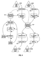
- FIG.4 is a state diagram according to an embodiment of the present disclosure.
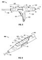
- FIG. 5 is a perspective view of another embodiment of an ablation device with a user interface at the handle in accordance with the present disclosure
- FIG. 6 is a perspective view of yet another embodiment of an ablation device with a user interface at the handle in accordance with the present disclosure
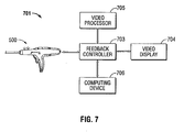
- FIG. 7 is a schematic diagram of a feedback control system in accordance with an embodiment of the present disclosure.
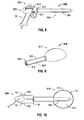
- FIG. 8 is a perspective view of an embodiment of an ablation device with a user interface at the handle in accordance with the present disclosure that includes a male connector disposed at the proximal end of the energy applicator;
- FIG.9 is a perspective view of an embodiment of a directional reflector assembly in accordance with the present disclosure that includes a tubular portion having a female connector adapted for attachment to the male connector of the ablation device of FIG. 8 ;
- FIG. 10 is a perspective view of the ablation device of FIG. 9 shown with the directional reflector assembly of FIG. 9 mounted on the probe thereof;
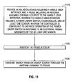
- FIG. 11 is a flowchart illustrating a method of ablating tissue.
- proximal refers to that portion of the apparatus that is closer to the user and the term “distal” refers to that portion of the apparatus that is farther from the user.
- a phrase in the form "A/B” means A or B.
- a phrase in the form "A and/or B” means "(A), (B), or (A and B)”.
- a phrase in the form "at least one of A, B, or C” means "(A), (B), (C), (A and B), (A and C), (B and C), or (A, B and C)".
- Electromagnetic energy is generally classified by increasing energy or decreasing wavelength into radio waves, microwaves, infrared, visible light, ultraviolet, X-rays and gamma-rays.
- microwave generally refers to electromagnetic waves in the frequency range of 300 megahertz (MHz) (3 x 10 8 cycles/second) to 300 gigahertz (GHz) (3 x 10 11 cycles/second).
- ablation procedure generally refers to any ablation procedure, such as microwave ablation, radio frequency (RF) ablation or microwave ablation assisted resection.
- energy applicator generally refers to any device that can be used to transfer energy from a power generating source, such as a microwave or RF electrosurgical generator, to tissue.
- transmission line generally refers to any transmission medium that can be used for the propagation of signals from one point to another.
- switch or “switches” generally refers to any electrical actuators, mechanical actuators, electro-mechanical actuators (rotatable actuators, pivotable actuators, toggle-like actuators, buttons, etc.) or optical actuators.
- length may refer to electrical length or physical length.
- electrical length is an expression of the length of a transmission medium in terms of the wavelength of a signal propagating within the medium. Electrical length is normally expressed in terms of wavelength, radians or degrees. For example, electrical length may be expressed as a multiple or sub-multiple of the wavelength of an electromagnetic wave or electrical signal propagating within a transmission medium. The wavelength may be expressed in radians or in artificial units of angular measure, such as degrees.
- the electric length of a transmission medium may be expressed as its physical length multiplied by the ratio of (a) the propagation time of an electrical or electromagnetic signal through the medium to (b) the propagation time of an electromagnetic wave in free space over a distance equal to the physical length of the medium.
- the electrical length is in general different from the physical length.
- an appropriate reactive element capacitor or inductive
- the electrical length may be made significantly shorter or longer than the physical length.
- Various embodiments of the present disclosure provide ablation devices with a user interface at the handle assembly (also referred to herein as a handle user interface) for treating tissue and methods of directing electromagnetic radiation to tissue.
- Embodiments may be implemented using electromagnetic radiation at microwave frequencies or at other frequencies.
- An electrosurgical system including an ablation device with a handle user interface is designed and configured to operate between about 500 MHz and about 10 GHz, and may provide a directional radiation pattern.
- Various embodiments of the presently disclosed ablation devices and electrosurgical system including the same are suitable for microwave ablation and for use to pre-coagulate tissue for microwave ablation assisted surgical resection.
- various methods described hereinbelow are targeted toward microwave ablation and the complete destruction of target tissue, it is to be understood that methods for directing electromagnetic radiation may be used with other therapies in which the target tissue is partially destroyed or damaged, such as, for example, to prevent the conduction of electrical impulses within heart tissue.
- a dipole microwave antenna the teachings of the present disclosure may also apply to a monopole, helical, or other suitable type of microwave antenna.
- any combination of battery cells, a battery pack, fuel cell and/or high-energy capacitor may be used to provide power to the ablation device (e.g., 200, 500 and 600 shown in FIGS. 1 , 5 and 6 , respectively).
- capacitors may be used in conjunction with a battery pack. ln such case, the capacitors may discharge a burst of power to provide energy more quickly than batteries are capable of providing, as batteries are typically slow-drain devices from which current cannot be quickly drawn. It is envisioned that batteries may be connected to the capacitors to charge the capacitors.
- a battery pack may include at least one disposable battery. ln such case, the disposable battery may be between about 9 volts and about 30 volts, and may be useful as a backup power source for the controller 20. ln some embodiments, a transmission line (e.g., 15 shown in FIGS. 1 and 5 ) is provided to connect the ablation device to an electrosurgical power generating source (e.g., 48 shown in FIG. 1 ).
- an electrosurgical power generating source e.g., 48 shown in FIG. 1
- FIG. 1 shows an electrosurgical system 10, according to an embodiment of the present disclosure that includes an ablation device 110.
- Ablation device 110 generally includes a handle assembly 30 including a grip portion 35 and a handle body 33 configured to support an energy applicator or probe 100 at a distal end 3 thereof.
- the handle body 33 includes a top portion "T", side portions "S” and a bottom portion "B".
- Probe 100 which is described in more detail later in this disclosure, generally includes an antenna assembly 12 having a radiating portion connected by a feedline 11 (or shaft) to the handle assembly 30.
- Antenna assembly 12 and the feedline 11 may have various dimensions, e.g., diameter and length.
- Handle assembly 30 is adapted to electrically couple the feedline 11 to a transmission line 15.
- the transmission line 15 may be coupled to a connector 16, which may further operably connect the probe 100 to an electrosurgical power generating source 48, e.g., a microwave or RF electrosurgical generator.
- an electrosurgical power generating source 48 e.g., a microwave or RF electrosurgical generator.
- a distal portion of the transmission line 15 may be disposed within the handle assembly 30, e.g., within the grip portion 35 and/or the handle body 33.
- Ablation device 110 includes a user interface (shown generally as 200 in FIG. 1 ) at the handle assembly 30.
- User interface 200 includes a controller 20 and includes a power on/off trigger or switch 21, a radiation detector 24, and an indicator unit 22 adapted to provide a perceptible sensory alert, which may be an audio, visual, or other sensory alarm.
- Controller 20 may include any type of computing device, computational circuit, or any type of processor or processing circuit capable of executing a series of instructions that are stored in a memory (not shown) of the controller 20.
- Power on/off trigger or switch 21, the radiation detector 24 and/or the indicator unit 22 may be electrically coupled to the controller 20.
- User interface 200 may additionally, or alternatively, include an intensity controller 25 adapted to allow the user to adjust the power parameters (e.g., voltage, power and/or current intensity) delivered to the probe 100.
- the user interface 200 may include a fluid-flow monitoring system 26 adapted to monitor and/or regulate the pressure and/or flow rate of fluid and capable of generating a signal indicative of an abnormal fluid circulation condition.
- the user interface 200 may include a reflected-power monitoring system 23 adapted to monitor power signals reflected from the probe 100.
- lntensity controller 25, the fluid-flow monitoring system 26 and/or the reflected-power monitoring system 23 may be electrically coupled to the controller 20.
- Indicator unit 22 may include audio and/or visual indicator devices.
- lndicator unit 22 includes an alarm or output component 220 that includes logic or circuitry to generate a signal when power is provided to the indicator unit 22.
- the indicator unit 22 is adapted to generate an audio signal and the output component 220 includes an audio circuit with a speaker 225.
- the indicator unit 22 is adapted to generate a visual signal and the output component 220 includes a light source, such as a light-emitting diode (LED).
- lndicator unit 22 may also include a display device (not shown), such as a flat panel display, e.g., a liquid crystal display (LCD), or other suitable display device, to provide information/feedback to a user.
- a display device not shown
- a flat panel display e.g., a liquid crystal display (LCD), or other suitable display device, to provide information/feedback to a user.
- LCD liquid crystal display
- the indicator unit 22 includes a first LED 221 and a second LED 222 in row configuration disposed on the top portion "T" of the handle body 33. It is envisioned that the first and second LEDs 221 and 222, respectively, provide information/feedback (e.g., visual feedback) to a user. For example, illumination of the first LED 221 may indicate that power is turned on, and illumination of the second LED 222 may indicate that power is turned off. First LED 221 and the second LED 222 may be uni- or multi-colored. ln an embodiment, the first LED 221 is a green LED, and the second LED 222 is a red LED.
- the first LED 221 may be a red LED
- the second LED 222 may be a green LED.
- the shape and size of the first and second LEDs 221 and 222, respectively, may be varied from the configuration depicted in FIG. 1 . It is contemplated that a single LED may be utilized in place of the first and second LEDs 221 and 222.
- Indicator unit 22 may additionally, or alternatively, include one or more audio indicator devices.
- a speaker 225 may be disposed on a side portion "S" of the handle body 33. It is contemplated that any number and size of speakers may be incorporated into the handle body 33 and/or the grip portion 35.
- the positions of the first and second LEDs 221 and 222, respectively, and the speaker 225, e.g., in relation to the distal end 3 of the handle body 33, may be varied from the configuration depicted in FIG. 1 .
- User interface 200 includes a power on/off switch 21.
- the power on/off switch 21 includes a trigger 211 located within a trigger guard 212.
- the shape and size of the trigger 211 and the trigger guard 212 may be varied from the configuration depicted in FIG. 1 .
- Power on/off switch 21 may utilize any suitable switch configuration. Examples of switch configurations that may be suitable for use with the ablation device 110 include, but are not limited to, pushbutton, toggle, rocker (e.g., 521 shown in FIG. 5 ), tactile, snap, rotary, slide (e.g., 621 shown in FIG. 6 ) and thumbwheel.
- Radiation detector 24 is electrically coupled to the controller 20, and may include any suitable device capable of detecting electromagnetic radiation and converting it to another form of energy such as electrical signals. ln some embodiments, the radiation detector 24 may include a radiation-absorbing layer and/or scintillator crystals. Examples of radiation detector embodiments are disclosed in commonly assigned U.S. Patent Application Serial No. 12/542,785 filed on August 18, 2009 , entitled “MICROWAVE ABLATION ANTENNA RADIATION DETECTOR", the disclosure of which is incorporated herein by reference in its entirety. ln the case where radiation is detected by the radiation detector 24, embodiments of the presently disclosed ablation devices transition to a power-off state (e.g., "S1" shown in FIG. 4 ). After taking corrective action when necessary, the user may activate the power on/off switch (e.g., 21 shown in FIG. 1 ) on the handle user interface to start, resume, or restart a procedure.
- a power-off state e.g., "S1" shown in FIG.
- the user interface 200 includes an intensity controller 25 slidingly supported on the handle body 33.
- the intensity controller 25 includes a pair of nubs (e.g., 251, 252 shown in FIG. 3 ) that are slidingly supported, one each, in respective guide channels 1, 2 formed in the outer surface of the handle body 33.
- nubs 251, 252 By providing nubs 251, 252 on either side "S" of the handle assembly 30, the intensity controller 25 may be easily manipulated by either hand of the user, allowing operation by a right- or a left-handed user.
- Intensity controller 25 is a slide-type potentiometer, wherein the nubs 251, 252 have a first position (e.g., a proximal-most position closest to the proximal end of the handle body 33) corresponding to a relative low-intensity setting, a second position (e.g., a distal-most position closest to the distal end 3 of the handle body 33) corresponding to a relative high-intensity setting, and a plurality of intermediate positions corresponding to intermediate intensity settings.
- the intensity settings from the proximal end to the distal end may be reversed as well, e.g., high to low.
- Nubs 251, 252 of the intensity controller 25 and the corresponding guide channels 1, 2 may be provided with a series of cooperating discrete positions or detents defining a series of positions for ease of selection of the output intensity from the low-intensity setting to the high-intensity setting.
- the series of cooperating discrete positions or detents may also provide the surgeon with a degree of tactile feedback.
- Intensity controller 25 is configured to adjust the power parameters (e.g., voltage, power and/or current intensity) and/or the power verses impedance curve shape to affect the perceived output intensity. For example, the greater the lateral displacement of the nubs 251, 252 in a distal direction, the greater the level of the power parameters transmitted to the ablation device 110.
- Intensity settings may be preset and selected from a look-up table, e.g., based on a choice of electrosurgical instruments/attachments, desired surgical effect, surgical specialty and/or surgeon preference. The selection may be made automatically or selected manually by the user.
- the intensity values may be predetermined or adjusted by the user.
- the intensity controller 25 may include indicia such as, for example, graduation marks "G” and/or wattage levels (e.g., "80W” or "140W”) provided thereon.
- the indicia may be etched, stamped, formed or the like, e.g., alongside the sides of the guide channels 1, 2 along which the nubs 251, 252 are slideably moveable. The design and location of the indicia may be varied from the configuration depicted in FIG. 1 .
- Intensity controller 25 may be adapted to provide a degree of tactile feedback, e.g., a tactile "click”. Additionally, or alternatively, audible feedback may be produced from the intensity controller 25 (e.g., an audible click), from electrosurgical power generating source 48 (e.g., an audible tone) and/or from the speaker 225 (e.g., an audible tone). Examples of audible tones include beep tones, click or tick tones, hum tones, steady tones, pulsing tones, and voice.
- intensity controller designs and different locations of the intensity controller on the handle assembly 30 may suitably be used.
- intensity controller embodiments are disclosed in commonly assigned U.S. Patent No. 7,156,844 , entitled “ELECTROSURGICAL PENCIL WITH IMPROVED CONTROLS", the disclosure of which is incorporated herein by reference in its entirety.
- the user interface 200 may include voice input technology, which may include hardware and/or software incorporated in the controller 20, or a separate digital module connected to the controller 20.
- the voice input technology may include voice recognition, voice activation, voice rectification, and/or embedded speech.
- the user may be able to control the operation of the ablation device in whole or in part through voice commands, e.g., freeing one or both of the user's hands for operating other instruments. Voice or other audible output may also be used to provide the user with feedback.
- Fluid-flow monitoring system 26 includes a sensor that is in fluid communication with the probe 100 that senses the pressure and/or flow rate of fluid flow in and/or out of the probe 100.
- the sensor is a mechanical sensor, such as a diaphragm or a piston.
- the sensor is an electrical sensor, such as a temperature-measuring resistor or electrical transducer.
- Fluid-flow monitoring system 26 may include a flow sensor that is adapted to provide a measurement of the rate of fluid flow in and/or out of the probe 100 and/or conduit fluidly coupled the probe 100.
- Fluid-flow monitoring system 26 may include a pressure sensor that provides a measurement of the fluid pressure in the probe 100 and/or conduit fluidly coupled the probe 100.
- a change in color of an LED may be used to indicate an abnormal fluid circulation condition, or the rate at which an LED flashes may be used to indicate fluid-flow speed and/or pressure.
- Examples of fluid-flow monitoring system embodiments are disclosed in commonly assigned U.S. Patent Application Serial No. 12/568,972 filed on September 29, 2009 , entitled “FLOW RATE MONITOR FOR FLUID COOLED MICROWAVE ABLATION PROBE", U.S. Patent Application Serial No. 12/566,299 filed on September 24, 2009 , entitled “OPTICAL DETECTION OF INTERRUPTED FLUID FLOW TO ABLATION PROBE", and U.S. Patent Application Serial No. 12/569,685 filed on September 29, 2009 , entitled “FLOW RATE MONITOR FOR FLUID COOLED MICROWAVE ABLATION PROBE", the disclosures of which are incorporated herein by reference in their entireties.
- Reflected-power monitoring system 23 is electrically coupled to the controller 20, and may include any suitable device capable of detecting power signals reflected back from probe 100. For example, energy may be reflected from ablated tissue and received by the antenna assembly 12. Energy not transferred to the antenna assembly 12 (e.g., when the antenna and feedline do not have matching impedances) may be reflected back towards the energy source.
- Reflected-power monitoring system 23 may include a power sensor to monitor forward and reflected power. The power sensor may measure the power output of the electrosurgical power generating source 48 that is utilized by the antenna assembly 12. Examples of power measurement system embodiments are disclosed in commonly assigned U.S. Patent Application Serial No.
- the controller 20 of the handle user interface 200 may cause the ablation device 110 to transition to a power-off state.
- User interface 200 includes different colors and/or intensities of text on screen and/or on switches for further differentiation between the displayed items.
- User feedback may also be included in the form of pulsed patterns of light, acoustic feedback (e.g., buzzers, bells or beeps that may be sounded at selected time intervals), verbal feedback, and/or haptic vibratory feedback (such as an asynchronous motor or solenoids), for example.
- the visual, auditory or haptic feedback e.g., level of vibratory feedback perceived by the user
- switches may be positioned at different heights from one another and/or may included raised indicia or other textural features (e.g., concavity or convexity) to allow a user to depress or otherwise move an appropriate switch without the need to look at the user interface 200.
- raised indicia or other textural features e.g., concavity or convexity
- User interface 200 may include a separate display screen or screens and input devices (e.g., switches or buttons), or the input devices may be incorporated in whole or in part in screen.
- a touch screen liquid crystal display LCD
- the touch screen LCD may include resistive, capacitive or surface acoustic wave controls. This approach may enable facilitation of sealing screen components to help sterilize the ablation device, as well as preventing particle and/or fluid contamination.
- a display screen is pivotably or rotatably mounted to the ablation device for flexibility in viewing the screen during use or preparation.
- the display screen may be hinged or ball-and-socket mounted to the ablation device, for example.
- the information monitored by the various sensors, e.g., radiation detector 24 and fluid-flow monitoring system 26, in the ablation device 110 may be provided to a video screen or monitoring system in an operating room.
- the data may be transmitted to a receiver for the operating room monitoring system from a communication transmitter incorporated in or associated with the ablation device, via technology including Bluetooth ® , ANT3 ® , KNX ® , Z-Wave ® , X10 ® , Wireless USB, Wi-Fi ® , IrDA ® , NanoNet ® , TinyOS ® , ZigBee ® , 802.11 IEEE, and other radio, infrared, UHF, VHF communications.
- Such features may facilitate monitoring by the user of the ablation device 110 or other operating room or hospital personnel or remotely located persons.
- Feedline 11 may be formed from any suitable flexible, semi-rigid or rigid microwave conductive cable and may connect directly to an electrosurgical power generating source 48. Alternatively, the feedline 11 may electrically connect the antenna assembly 12 via the transmission line 15 to the electrosurgical power generating source 48: Feedline 11 may have a variable length from a proximal end of the antenna assembly 12 to a distal end of transmission line 15 ranging from a length of about one inch to about twelve inches. Feedline 11 may be formed of suitable electrically conductive materials, e.g., copper, gold, silver or other conductive metals having similar conductivity values.
- Feedline 11 may be made of stainless steel, which generally offers the strength required to puncture tissue and/or skin. Conductive materials used to form the feedline 11 may be plated with other materials, e.g., other conductive materials, such as gold or silver, to improve their properties, e.g., to improve conductivity, decrease energy loss, etc. ln some embodiments, the feedline 11 includes stainless steel, and to improve the conductivity thereof, the stainless steel may be coated with a layer of a conductive material such as copper or gold. Feedline 11 may include an inner conductor, a dielectric material coaxially surrounding the inner conductor, and an outer conductor coaxially surrounding the dielectric material.
- Antenna assembly 12 may be formed from a portion of the inner conductor that extends distal of the feedline 11 into the antenna assembly 12.
- Feedline 11 may be cooled by fluid e.g., saline or water, to improve power handling, and may include a stainless steel catheter.
- the power generating source 48 is configured to provide microwave energy at an operational frequency from about 500 MHz to about 2500 MHz. ln other embodiments, the power generating source 48 is configured to provide microwave energy at an operational frequency from about 500 MHz to about 10 GHz. Power generating source 48 may be configured to provide various frequencies of electromagnetic energy. Transmission line 15 may additionally, or alternatively, provide a conduit (not shown) configured to provide coolant from a coolant source 18 to the probe 100.
- an end cap or tapered portion 120 Located at the distal end of the antenna assembly 12 is an end cap or tapered portion 120 that may terminate in a sharp tip 123 to allow for insertion into tissue with minimal resistance.
- the end cap or tapered portion 120 may include other shapes, such as, for example, a tip 123 that is rounded, flat, square, hexagonal, or cylindroconical.
- the antenna assembly 12 includes a distal radiating portion 105 and a proximal radiating portion 140.
- a junction member 130 may be provided. Junction member 130, or portions thereof, may be disposed between the proximal and distal radiating portions, 140 and 105, respectively. ln some embodiments, the distal and proximal radiating portions 105, 140 align at the junction member 130, which is generally made of a dielectric material, e.g., adhesives, and are also supported by the inner conductor that extends at least partially through the distal radiating portion 105.
- Junction member 130 may be formed from any suitable elastomeric or ceramic dielectric material by any suitable process.
- the junction member 130 is formed by over-molding and includes a thermoplastic elastomer, such as, for example, polyether block amide (e.g., PEBAX ® , manufactured by The Arkema Group of Colombes, France), polyetherimide (e.g., ULTEM ® and/or EXTEM ® , manufactured by SABIC Innovative Plastics of Saudi Arabia) and/or polyimide-based polymer (e.g., VESPEL ® , manufactured by E. I. du Pont de Nemours and Company of Wilmington, Delaware, United States).
- Junction member 130 may be formed using any suitable over-molding compound by any suitable process, and may include use of a ceramic substrate.
- the antenna assembly 12 may be provided with a coolant chamber (not shown).
- the junction member 130 may include coolant inflow and outflow ports (not shown) to facilitate the flow of coolant into, and out of, the coolant chamber. Examples of coolant chamber and coolant inflow and outflow port embodiments are disclosed in commonly assigned U.S. Patent Application Serial No. 12/401,268 filed on March 10, 2009 , entitled “COOLED DIELECTRICALLY BUFFERED MICROWAVE DIPOLE ANTENNA", and U.S. Patent No. 7,311,703 , entitled “DEVICES AND METHODS FOR COOLING MICROWAVE ANTENNAS".
- the antenna assembly 12 may be provided with an outer jacket (not shown) disposed about the distal radiating portion 105, the junction 130 and/or the proximal radiating portion 140.
- the outer jacket may be formed of any suitable material, such as, for example, polymeric or ceramic materials.
- the outer jacket may be applied by any suitable method, such as, for example, heat shrinking, over-molding, coating, spraying dipping, powder coating, baking and/or film deposition.
- the outer jacket may be a water-cooled catheter formed of a material having low electrical conductivity.
- the probe 100 is inserted into or placed adjacent to tissue and energy is supplied thereto.
- Ultrasound or computed tomography (CT) guidance may be used to accurately guide the probe 100 into the area of tissue to be treated.
- Probe 100 may be placed percutaneously or surgically, e.g., using conventional surgical techniques by surgical staff.
- a clinician may pre-determine the length of time that microwave energy is to be applied. Application duration may depend on many factors such as tumor size and location and whether the tumor was a secondary or primary cancer.
- the duration of microwave energy application using the probe 100 may depend on the progress of the heat distribution within the tissue area that is to be destroyed and/or the surrounding tissue.
- Single or multiple probes 100 may provide ablations in short procedure times, e.g., a few minutes, to destroy cancerous cells in the target tissue region.
- a plurality of probes 100 may be placed in variously-arranged configurations to substantially simultaneously ablate a target tissue region, making faster procedures possible. Multiple probes 100 may be used to synergistically create a large ablation or to ablate separate sites simultaneously. Tissue ablation size and geometry is influenced by a variety of factors, such as the energy applicator design, number of energy applicators used simultaneously, ablation time and wattage, and tissue characteristics.
- microwave energy having a wavelength, lambda ( ⁇ ) is transmitted through the antenna assembly 12, e.g., along the proximal and distal radiating portions 140, 105, and radiated into the surrounding medium, e.g., tissue.
- the length of the antenna for efficient radiation may be dependent on the effective wavelength ⁇ eff that is dependent upon the dielectric properties of the medium being radiated.
- Antenna assembly 12 through which microwave energy is transmitted at a wavelength ⁇ may have differing effective wavelengths ⁇ eff depending upon the surrounding medium, e.g., liver tissue as opposed to breast tissue.
- an embodiment of the antenna assembly 12 of FIG. 1 includes an inner conductor 210, an outer conductor 260, and may include a first dielectric material 240 separating the inner conductor 210 and the outer conductor 260.
- the inner conductor 210 is formed from a first electrically conductive material (e.g., stainless steel) and the outer conductor 260 is formed from a second electrically conductive material (e.g., copper).
- the outer conductor 260 coaxially surrounds the inner conductor 210 along a distal portion of the antenna assembly 12.
- Inner conductor 210 and the outer conductor 260 may be formed from any suitable electrically conductive material.
- First dielectric material 240 may be formed from any suitable dielectric material, including, but not limited to, ceramics, water, mica, polyethylene, polyethylene terephthalate, polyimide, polytetrafluoroethylene (a.k.a. PTFE or Teflon ® , manufactured by E. I. du Pont de Nemours and Company of Wilmington, Delaware, United States), glass, or metal oxides.
- Antenna assembly 12 may be provided with a second dielectric material 290 surrounding the outer conductor 260 and/or the puck 130, or portions thereof.
- Second dielectric material 290 may be formed from any suitable dielectric material.
- the second dielectric material 290 is formed form a material with a dielectric constant different than the dielectric constant of the first dielectric material 240.
- the antenna assembly 12 includes a conductor end portion 280, which may be formed from any suitable electrically conductive material.
- the conductor end portion 280 is coupled to the inner conductor 210 and may be formed of the same material as the inner conductor 210. As shown in FIG. 2 , the conductor end portion 280 may be spaced apart from the outer conductor 260 by the puck 130 disposed therebetween. Tapered region 120, or portions thereof, may surround a proximal portion of the conductor end portion 280.
- the conductor end portion 280 is substantially cylindrically shaped, and may be formed from stainless steel. The shape and size of the conductor end portion 280 may be varied from the configuration depicted in FIG. 2 . In some embodiments, at least a portion of the conductor end portion 280 is surrounded by the second dielectric material 290.
- FIG. 4 illustrates an embodiment of a state diagram in accordance with the present disclosure that describes behavior of a handle user interface with respect to power on/off status, fluid circulation status, radiation detector status, and reflected power status.
- handle user interface embodiments that may operate in accordance with the state diagram of FIG. 4 include the handle user interface 200 of FIG. 1 .
- the handle user interface 200 includes a power on/off switch 21, a fluid-flow monitoring system 26, a radiation detector 24, and a reflected-power monitoring system 23, and an intensity controller 25.
- Ablation devices configured with a handle user interface according to other embodiments of the present disclosure are shown in FIGS. 5, 6 and 8 , as described later in this disclosure.
- power on/off status is described below in terms of microwave (MW) power
- ablation device embodiments described by the state diagram of FIG. 4 may be implemented using electromagnetic radiation at microwave frequencies or at other frequencies.
- the action 421 of activating the power on/off switch transitions the presently disclosed ablation device to a power-off state "S1" if it is determined that the MW power is currently on when the power on/off switch is activated, or alternatively, results in a transition to a power-on state "S2" if it is determined that the MW power is currently off when the power on/off switch is activated.
- MW power is off
- the green LED e.g., 221 shown in FIG. 1
- the red LED e.g., 222 shown in FIG. 1
- the action 421 of activating the power on/off switch may result in a transition out of the power-off state "S1" if it is determined that the switch activation turns MW power on, or alternatively, may result in a transition out of the power-on state "S2" if it is determined that the switch activation turns MW power off.
- a power-level-control sample 525 may be used to determine whether a power-level change has been input, e.g., by user operation of the intensity controller 25. ln the case where it is determined that the power level has been incremented, MW power may be increased, for example. It is contemplated that visual, auditory and/or haptic feedback may be associated with an increase in the power level and/or a decrease in the power level.
- a radiation-detector sample 424 may be used to determine whether radiation is detected.
- Handle user interface embodiments e.g., 200, 500 and 600 shown in FIGS. 1 , 5 and 6 , respectively
- S1 the power-off state
- a reflected power, P ref , sample 423 may be used to determine whether power signals reflected from the probe 100 are detected. As shown in FIG. 4 , based on the comparison result of a comparison of P ref to a predetermined threshold value, the handle user interface may cause the ablation device to transition to the power-off state "S1".
- the predetermined threshold value may be obtained from a look-up table, e.g., based on a choice of electrosurgical instruments/attachments.
- FIG. 5 shows an ablation device 500 according to an embodiment of the present disclosure that is similar to the ablation device 110 of FIG. 1 , except for the shape of the handle body 530, the configuration of the power on/off switch 521, and the configuration of the indicator unit 520.
- Ablation device 500 includes the controller 20, the radiation detector 24, the reflected-power monitoring system 23, and the intensity controller 25, and the first and second LEDs 221, 222 of FIG. 1 , and further description thereof is omitted in the interests of brevity.
- Indicator unit 520 is generally adapted to provide a visual sensory alarm.
- the indicator unit 520 includes the first LED 221 and the second LED 222 in a row configuration disposed on a top, proximal portion of the handle body 533.
- the shape, size and location of the first and second LEDs 221, 222 may be varied from the configuration depicted in FIG. 5 .
- Indicator unit 520 may additionally, or alternatively, be adapted to provide audio and/or other perceptible sensory alerts.
- Power on/off switch 521 may be any suitable switch that generally fulfills the purpose of switching electrical circuits on and off or switching over from one electrical circuit to another.
- the power on/off switch 521 is a rocker-type switch that generally includes two wing portions projecting from opposite sides of a rotational axis for alternatingly engaging depressible operators of the switch 521.
- FIG. 6 shows an ablation device 600 according to an embodiment of the present disclosure that is similar to the ablation device 110 of FIG. 1 , except for the shape of the handle body 630, the configuration of the power on/off switch 621, and the configuration of the indicator unit 620.
- Ablation device 600 includes at least the radiation detector 24, the intensity controller 25, and the first and second LEDs 221, 222 of FIG. 1 , and further description thereof is omitted in the interests of brevity.
- the indicator unit 520 may include the first LED 221 and the second LED 222 of FIG. 1 and a third LED 623.
- a change in color of the third LED 623 may be used to indicate an abnormal fluid circulation condition.
- the power on/off switch 621 is a slider-type switch. The shape, size and location of the power on/off switch 621 may be varied from the configuration depicted in FIG. 6 .
- Embodiments of the present disclosure may include a feedback control system 701 as shown in FIG. 7 .
- the feedback control system 701 includes a feedback controller 703.
- An ablation device e.g., 500 shown in FIG. 5
- a data port (not shown) is connected to the feedback controller 703 via the data port, which may be wired (e.g., FireWire®, USB, Serial RS232, Serial RS485, USART, Ethernet, etc.) and/or wireless (e.g., Bluetooth ® , ANT3 ® , KNX ® , Z-Wave ® , X10 ® , Wireless USB, Wi-Fi ® , IrDA ® , NanoNet ® , TinyOS ® , ZigBee ® , 802.11 IEEE, and other radio, infrared, UHF, VHF communications and the like).
- wired e.g., FireWire®, USB, Serial RS232, Serial RS485, USART,
- the feedback controller 703 is configured to store the data transmitted by the ablation device to the feedback controller 703 as well as process and analyze the data.
- Feedback controller 703 is also connected to other devices, such as a video display 704, a video processor 705 and a computing device 706, e.g., a personal computer, a personal digital assistant (PDA), a smartphone, a storage device, etc.
- Video processor 705 is adapted to process output data generated by the feedback controller 603 for output on the video display 704.
- Computing device 706 is adapted for processing of the feedback data. ln one embodiment, the results of the sensor feedback analysis performed by the controller 524 may be stored internally for later retrieval by the computing device 706.
- FIG. 8 shows an ablation device 800 according to an embodiment of the present disclosure that is similar to the ablation device 110 of FIG. 1 , except for the shape of the handle body 833 and a male connector disposed at the proximal end of the probe 860.
- Ablation device 800 includes the handle user interface of FIG. 1 , and further description thereof is omitted in the interests of brevity.
- Handle body 833 is operably associated with the male connector 812.
- the male connector 812 includes a retainer member 811 that is movable between at least an engagement position and a released position.
- the handle body 833 may include a user operable switch 815, e.g., a push button, operable to move the male connector 812 from an engagement position, in which the retainer member 811 is engaged with a female connector (e.g., 916 shown in FIG. 9 ), to a released position, in which the retainer member 811 is disengaged from the female connector.
- the shape and size of the male connector 812 may be varied from the configuration depicted in FIG. 8 .
- FIG.9 shows an embodiment of a directional reflector assembly 910 in accordance with the present disclosure that includes a shell assembly 917, a tubular portion 930 defining a lumen 934, and a female connector 916 associated with the proximal end 905 of the tubular portion 930.
- Female connector 916 is adapted for engagement with the male connector 812 of the ablation device 800 of FIG. 8.
- FIG. 10 is a bottom view of the ablation device 800 of FIG. 8 shown with the directional reflector assembly 910 of FIG. 9 mounted on the probe 860 thereof.
- Shell assembly 917 includes an outer portion 911 and an inner portion 912, and may include a recess defined in a planar surface "S" of the inner portion 912 generally configured to receive a distal portion 861 of probe 860 therein.
- Outer portion 911 may include an electrically conductive material, such as, for example, copper, stainless steel, titanium, titanium alloys such as nickel-titanium and titanium-aluminum-vanadium alloys, aluminum, aluminum alloys, tungsten carbide alloys or combinations thereof. Portions of the outer portion 911 may be loaded with low- to mid-range permittivity dielectric materials to aid in radiation directivity and impedance matching. In general, the dielectric permittivity would increase in value with radial distance from the electrically-conductive member 911. Several shells, or other shapes, of different dielectric materials may nest together to form the outer portion 911.
- Inner portion 912 may include a dielectric material.
- the inner portion 912 includes dielectric material layers.
- the inner portion 912 may include one or more thin layers, one or more thick layers or a mixture of thick and thin layers.
- Inner portion 912 may be composed of any suitable dielectric material which may be the same as, or different from, the dielectric material, if any, used in the outer portion 911.
- the dielectric materials used to form the inner portion 912 may vary in dielectric constant with shells or more complex dielectric layering to achieve the optimum antenna directivity and energy to tissue delivery.
- Shell assembly 917 may be shaped in such a manner to provide a desired surface ablation shape as well as aid in impedance matching. Shell assembly 917 may have any suitable shape and may be designed for tight spaces encountered during surgical operations. Examples of shell assembly embodiments are disclosed in commonly assigned U.S. Patent Application Serial No. 12/568,524 filed on September 28, 2009 , entitled "ELECTROSURGICAL DEVICES, DIRECTIONAL REFLECTOR ASSEMBLIES COUPLEABLE THERETO, AND ELECTROSURGICAL SYSTEMS INCLUDING SAME", the disclosure of which is incorporated herein by reference in its entirety.
- the above-described ablation devices with a user interface at the handle for treating tissue may be used to provide directional microwave ablation, wherein the heating zone may be focused to one side of the electrosurgical device, thereby allowing clinicians to target small and/or hard tumors without having to penetrate the tumor directly or affect more healthy tissue than necessary.
- the presently disclosed ablation devices with a user interface at the handle and directional reflector assemblies may allow clinicians to avoid ablating critical structures, such as large vessels, healthy organs or vital membrane barriers, by placing the electrosurgical device between the tumor and critical structure and directing the electromagnetic radiation toward the tumor and away from the sensitive structure.
- FIG. 11 is a flowchart illustrating a method of directing energy to tissue according to an embodiment of the present disclosure.
- an ablation device e.g., 110 shown in FIGS. 1 and 3
- the ablation device includes a handle user interface (e.g., 200 shown in FIG. 1 ) and a probe (e.g., 110 shown in FIG. 1 ) including an antenna assembly (e.g., 12 shown in FIGS. 1 and 2 ) operably coupled to the handle user interface.
- the handle user interface includes a power on/off switch (e.g., 21 shown in FIG. 1 ), a controller (e.g., 20 shown in FIG. 1 ), and at least one sensor (e.g., radiation detector 24 shown in FIG.
- controller is configured to override operation of the power on/off switch in response to an electrical signal generated by the at least one sensor.
- the controller may be configured to override operation of the power on/off switch by transitioning the ablation device to a power-off state (e.g., "S1" shown in FIG. 4 ).
- the ablation device (e.g., 110 shown in FIG. 1 ) is positioned to tissue.
- the ablation device may be inserted directly into tissue, inserted through a lumen, e.g., a vein, needle or catheter, placed into the body during surgery by a clinician, or positioned in the body by other suitable methods.
- the ablation device may be configured to operate with a directional radiation pattern.
- step 1130 energy is transmitted from an energy source (e.g., shown in FIG. 1 ) through the antenna assembly (e.g., 12 shown in FIGS. 1 and 2 ) to tissue.
- the energy source may be any suitable electrosurgical generator for generating an output signal.
- the energy source is a microwave energy source, and may be configured to provide microwave energy at an operational frequency from about 500 MHz to about 10 GHz.
- the energy source supplies power having a selected phase, amplitude and frequency.
Abstract
Description
- The present disclosure relates to electrosurgical devices suitable for use in tissue ablation applications and, more particularly, to ablation devices with a user interface at the device handle, systems including the same, and methods of ablating tissue using the same.
- Treatment of certain diseases requires the destruction of malignant tissue growths, e.g., tumors. Electromagnetic radiation can be used to heat and destroy tumor cells. Treatment may involve inserting ablation probes into tissues where cancerous tumors have been identified. Once the probes are positioned, electromagnetic energy is passed through the probes into surrounding tissue.
- In the treatment of diseases such as cancer, certain types of tumor cells have been found to denature at elevated temperatures that are slightly lower than temperatures normally injurious to healthy cells. Known treatment methods, such as hyperthermia therapy, heat diseased cells to temperatures above 41° C while maintaining adjacent healthy cells below the temperature at which irreversible cell destruction occurs. These methods involve applying electromagnetic radiation to heat, ablate and/or coagulate tissue. Microwave energy is sometimes utilized to perform these methods. Other procedures utilizing electromagnetic radiation to heat tissue also include coagulation, cutting and/or ablation of tissue.
- Electrosurgical devices utilizing electromagnetic radiation have been developed for a variety of uses and applications. A number of devices are available that can be used to provide high bursts of energy for short periods of time to achieve cutting and coagulative effects on various tissues. There are a number of different types of apparatus that can be used to perform ablation procedures. Typically, microwave apparatus for use in ablation procedures include a microwave generator that functions as an energy source, and a microwave surgical instrument (e.g., microwave ablation probe) having an antenna assembly for directing the energy to the target tissue. The microwave generator and surgical instrument are typically operatively coupled by a cable assembly having a plurality of conductors for transmitting microwave energy from the generator to the instrument, and for communicating control, feedback and identification signals between the instrument and the generator.
- There are several types of microwave probes in use, e.g., monopole, dipole and helical, which may be used in tissue ablation applications. ln monopole and dipole antenna assemblies, microwave energy generally radiates perpendicularly away from the axis of the conductor. Monopole antenna assemblies typically include a single, elongated conductor. A typical dipole antenna assembly includes two elongated conductors that are linearly aligned and positioned end-to-end relative to one another with an electrical insulator placed therebetween. Helical antenna assemblies include helically-shaped conductor configurations of various dimensions, e.g., diameter and length. The main modes of operation of a helical antenna assembly are normal mode (broadside), in which the field radiated by the helix is maximum in a perpendicular plane to the helix axis, and axial mode (end fire), in which maximum radiation is along the helix axis.
- A microwave transmission line typically includes a long, thin inner conductor that extends along the longitudinal axis of the transmission line and is surrounded by a dielectric material and is further surrounded by an outer conductor around the dielectric material such that the outer conductor also extends along the transmission line axis. ln one variation of an antenna, a waveguiding structure, such as a length of transmission line or coaxial cable, is provided with a plurality of openings through which energy "leaks" or radiates away from the guiding structure. This type of construction is typically referred to as a "leaky coaxial" or "leaky wave" antenna.
- Cooling the ablation probe may enhance the overall heating pattern of the antenna, prevent damage to the antenna and prevent harm to the clinician or patient. Because of the small temperature difference between the temperature required for denaturing malignant cells and the temperature normally injurious to healthy cells, a known heating pattern and precise temperature control is needed to lead to more predictable temperature distribution to eradicate the tumor cells while minimizing the damage to surrounding normal tissue.
- During certain procedures, it can be difficult to assess the extent to which the microwave energy will radiate into the surrounding tissue, making it difficult to determine the area or volume of surrounding tissue that will be ablated. Ablation volume is correlated to antenna design, antenna performance, antenna impedance, ablation time and wattage, and tissue characteristics, e.g., tissue impedance. The particular type of tissue ablation procedure may dictate a particular ablation volume in order to achieve a desired surgical outcome. By way of example and without limitation, a spinal ablation procedure may call for a longer, narrower ablation volume, whereas in a prostate ablation procedure a more spherical ablation volume may be required.
- In some instances, targeted lesions may be located on or near the surface of the target organ. Some ablation targeted lesions are too small or too hard to be punctured by an ablation probe. ln these cases, doctors may place the probe as close as possible to the lesion and perform an ablation. With non-directional ablation probes, the ablation may radiate to both sides of the probe.
- Treatment of certain tumors may involve probe repositioning during the ablation procedure, such as where the tumor is larger than the probe or has a shape that does not correspond with available probe geometry or radiation pattern. The surgeon, before or after treatment is completed, may remove the probe from tissue while power is delivered to the probe antenna and an unintentional radiation exposure may occur.
- The present disclosure relates to an ablation device including a handle assembly including a distal end, an ablation probe extending distally from the distal end of the handle assembly, and a user interface disposed at the handle assembly. The ablation probe is operably coupled to the user interface. The user interface includes a controller unit, a power on/off switch, and at least one sensor capable of generating an electrical signal. The controller is in communication with the at least one detector and configured to override operation of the power on/off switch in response to the electrical signal generated by the at least one detector.
- The present disclosure also relates to a system for ablating tissue including an energy source and an ablation device. The ablation device includes a handle assembly, a user interface disposed on the handle assembly, and a probe operably coupled to the user interface extending distally from a distal end of the handle assembly.
- The present disclosure also relates to a method of ablating tissue including the steps of providing an ablation device including a handle user interface and a probe. The probe includes an antenna assembly operably coupled to the handle user interface. The handle user interface includes a power on/off switch, a controller, and at least one sensor. The method also includes the steps of positioning the probe in tissue, transmitting energy from an energy source through the antenna assembly to tissue, and overriding operation of the power on/off switch in response to an electrical signal generated by the at least one sensor.
- Objects and features of the presently disclosed ablation device with a user interface at the handle, system including the same, and method of ablating tissue using the same will become apparent to those of ordinary skill in the art when descriptions of various embodiments thereof are read with reference to the accompanying drawings, of which:
-
FIG. 1 is a schematic diagram of an ablation system in accordance with an embodiment of the present disclosure; -
FIG. 2 is a partial, longitudinal cross-sectional view of an embodiment of the energy applicator of the ablation system shown inFIG. 1 in accordance with the present disclosure; -
FIG. 3 is a bottom perspective view of the ablation device ofFIG. 1 according to an embodiment of the present disclosure; -
FIG.4 is a state diagram according to an embodiment of the present disclosure; -
FIG. 5 is a perspective view of another embodiment of an ablation device with a user interface at the handle in accordance with the present disclosure; -
FIG. 6 is a perspective view of yet another embodiment of an ablation device with a user interface at the handle in accordance with the present disclosure; -
FIG. 7 is a schematic diagram of a feedback control system in accordance with an embodiment of the present disclosure; -
FIG. 8 is a perspective view of an embodiment of an ablation device with a user interface at the handle in accordance with the present disclosure that includes a male connector disposed at the proximal end of the energy applicator; -
FIG.9 is a perspective view of an embodiment of a directional reflector assembly in accordance with the present disclosure that includes a tubular portion having a female connector adapted for attachment to the male connector of the ablation device ofFIG. 8 ; -
FIG. 10 is a perspective view of the ablation device ofFIG. 9 shown with the directional reflector assembly ofFIG. 9 mounted on the probe thereof; and -
FIG. 11 is a flowchart illustrating a method of ablating tissue. - Hereinafter, embodiments of the presently disclosed ablation device with a handle user interface, system including the same, and method of ablating tissue using the same will be described with reference to the accompanying drawings. Like reference numerals may refer to similar or identical elements throughout the description of the figures. As shown in the drawings and as used in this description, and as is traditional when referring to relative positioning on an object, the term "proximal" refers to that portion of the apparatus that is closer to the user and the term "distal" refers to that portion of the apparatus that is farther from the user.
- This description may use the phrases "in an embodiment," "in embodiments," "in some embodiments," or "in other embodiments," which may each refer to one or more of the same or different embodiments in accordance with the present disclosure. For the purposes of this description, a phrase in the form "A/B" means A or B. For the purposes of the description, a phrase in the form "A and/or B" means "(A), (B), or (A and B)". For the purposes of this description, a phrase in the form "at least one of A, B, or C" means "(A), (B), (C), (A and B), (A and C), (B and C), or (A, B and C)".
- Electromagnetic energy is generally classified by increasing energy or decreasing wavelength into radio waves, microwaves, infrared, visible light, ultraviolet, X-rays and gamma-rays. As it is used in this description, "microwave" generally refers to electromagnetic waves in the frequency range of 300 megahertz (MHz) (3 x 10⁸ cycles/second) to 300 gigahertz (GHz) (3 x 10¹¹ cycles/second). As it is used in this description, "ablation procedure" generally refers to any ablation procedure, such as microwave ablation, radio frequency (RF) ablation or microwave ablation assisted resection. As it is used in this description, "energy applicator" generally refers to any device that can be used to transfer energy from a power generating source, such as a microwave or RF electrosurgical generator, to tissue.
- As it is used in this description, "transmission line" generally refers to any transmission medium that can be used for the propagation of signals from one point to another. As it is used in this description, "switch" or "switches" generally refers to any electrical actuators, mechanical actuators, electro-mechanical actuators (rotatable actuators, pivotable actuators, toggle-like actuators, buttons, etc.) or optical actuators.
- As it is used in this description, "length" may refer to electrical length or physical length. ln general, electrical length is an expression of the length of a transmission medium in terms of the wavelength of a signal propagating within the medium. Electrical length is normally expressed in terms of wavelength, radians or degrees. For example, electrical length may be expressed as a multiple or sub-multiple of the wavelength of an electromagnetic wave or electrical signal propagating within a transmission medium. The wavelength may be expressed in radians or in artificial units of angular measure, such as degrees. The electric length of a transmission medium may be expressed as its physical length multiplied by the ratio of (a) the propagation time of an electrical or electromagnetic signal through the medium to (b) the propagation time of an electromagnetic wave in free space over a distance equal to the physical length of the medium. The electrical length is in general different from the physical length. By the addition of an appropriate reactive element (capacitive or inductive), the electrical length may be made significantly shorter or longer than the physical length.
- Various embodiments of the present disclosure provide ablation devices with a user interface at the handle assembly (also referred to herein as a handle user interface) for treating tissue and methods of directing electromagnetic radiation to tissue. Embodiments may be implemented using electromagnetic radiation at microwave frequencies or at other frequencies. An electrosurgical system including an ablation device with a handle user interface, according to various embodiments, is designed and configured to operate between about 500 MHz and about 10 GHz, and may provide a directional radiation pattern.
- Various embodiments of the presently disclosed ablation devices and electrosurgical system including the same are suitable for microwave ablation and for use to pre-coagulate tissue for microwave ablation assisted surgical resection. Although various methods described hereinbelow are targeted toward microwave ablation and the complete destruction of target tissue, it is to be understood that methods for directing electromagnetic radiation may be used with other therapies in which the target tissue is partially destroyed or damaged, such as, for example, to prevent the conduction of electrical impulses within heart tissue. ln addition, although the following description describes the use of a dipole microwave antenna, the teachings of the present disclosure may also apply to a monopole, helical, or other suitable type of microwave antenna.
- lt is envisioned that any combination of battery cells, a battery pack, fuel cell and/or high-energy capacitor may be used to provide power to the ablation device (e.g., 200, 500 and 600 shown in
FIGS. 1 ,5 and 6 , respectively). For example, capacitors may be used in conjunction with a battery pack. ln such case, the capacitors may discharge a burst of power to provide energy more quickly than batteries are capable of providing, as batteries are typically slow-drain devices from which current cannot be quickly drawn. It is envisioned that batteries may be connected to the capacitors to charge the capacitors. - A battery pack may include at least one disposable battery. ln such case, the disposable battery may be between about 9 volts and about 30 volts, and may be useful as a backup power source for the
controller 20. ln some embodiments, a transmission line (e.g., 15 shown inFIGS. 1 and5 ) is provided to connect the ablation device to an electrosurgical power generating source (e.g., 48 shown inFIG. 1 ). -
FIG. 1 shows anelectrosurgical system 10, according to an embodiment of the present disclosure that includes anablation device 110.Ablation device 110 generally includes ahandle assembly 30 including agrip portion 35 and ahandle body 33 configured to support an energy applicator or probe 100 at adistal end 3 thereof. As cooperatively shown inFIGS. 1 and3 , thehandle body 33 includes a top portion "T", side portions "S" and a bottom portion "B".Probe 100, which is described in more detail later in this disclosure, generally includes anantenna assembly 12 having a radiating portion connected by a feedline 11 (or shaft) to thehandle assembly 30.Antenna assembly 12 and thefeedline 11 may have various dimensions, e.g., diameter and length. Handleassembly 30 according to various embodiments is adapted to electrically couple thefeedline 11 to atransmission line 15. As shown inFIG. 1 , thetransmission line 15 may be coupled to aconnector 16, which may further operably connect theprobe 100 to an electrosurgicalpower generating source 48, e.g., a microwave or RF electrosurgical generator. ln some embodiments, a distal portion of thetransmission line 15 may be disposed within thehandle assembly 30, e.g., within thegrip portion 35 and/or thehandle body 33. -
Ablation device 110 according to embodiments of the present disclosure includes a user interface (shown generally as 200 inFIG. 1 ) at thehandle assembly 30.User interface 200 according to embodiments of the present disclosure includes acontroller 20 and includes a power on/off trigger or switch 21, aradiation detector 24, and anindicator unit 22 adapted to provide a perceptible sensory alert, which may be an audio, visual, or other sensory alarm.Controller 20 may include any type of computing device, computational circuit, or any type of processor or processing circuit capable of executing a series of instructions that are stored in a memory (not shown) of thecontroller 20. Power on/off trigger or switch 21, theradiation detector 24 and/or theindicator unit 22 may be electrically coupled to thecontroller 20. -
User interface 200 may additionally, or alternatively, include anintensity controller 25 adapted to allow the user to adjust the power parameters (e.g., voltage, power and/or current intensity) delivered to theprobe 100. ln some embodiments, theuser interface 200 may include a fluid-flow monitoring system 26 adapted to monitor and/or regulate the pressure and/or flow rate of fluid and capable of generating a signal indicative of an abnormal fluid circulation condition. ln some embodiments, theuser interface 200 may include a reflected-power monitoring system 23 adapted to monitor power signals reflected from theprobe 100.lntensity controller 25, the fluid-flow monitoring system 26 and/or the reflected-power monitoring system 23 may be electrically coupled to thecontroller 20. -
Indicator unit 22 may include audio and/or visual indicator devices.lndicator unit 22 according to various embodiments includes an alarm oroutput component 220 that includes logic or circuitry to generate a signal when power is provided to theindicator unit 22. ln some embodiments, theindicator unit 22 is adapted to generate an audio signal and theoutput component 220 includes an audio circuit with aspeaker 225. ln some embodiments, theindicator unit 22 is adapted to generate a visual signal and theoutput component 220 includes a light source, such as a light-emitting diode (LED).lndicator unit 22 may also include a display device (not shown), such as a flat panel display, e.g., a liquid crystal display (LCD), or other suitable display device, to provide information/feedback to a user. - In the embodiment illustrated in
FIG. 1 , theindicator unit 22 includes afirst LED 221 and asecond LED 222 in row configuration disposed on the top portion "T" of thehandle body 33. It is envisioned that the first andsecond LEDs first LED 221 may indicate that power is turned on, and illumination of thesecond LED 222 may indicate that power is turned off.First LED 221 and thesecond LED 222 may be uni- or multi-colored. ln an embodiment, thefirst LED 221 is a green LED, and thesecond LED 222 is a red LED. As can be appreciated, thefirst LED 221 may be a red LED, and thesecond LED 222 may be a green LED. The shape and size of the first andsecond LEDs FIG. 1 . It is contemplated that a single LED may be utilized in place of the first andsecond LEDs -
Indicator unit 22 may additionally, or alternatively, include one or more audio indicator devices. As cooperatively shown inFIGS. 1 and3 , aspeaker 225 may be disposed on a side portion "S" of thehandle body 33. It is contemplated that any number and size of speakers may be incorporated into thehandle body 33 and/or thegrip portion 35. The positions of the first andsecond LEDs speaker 225, e.g., in relation to thedistal end 3 of thehandle body 33, may be varied from the configuration depicted inFIG. 1 . -
User interface 200 according to various embodiments includes a power on/offswitch 21. ln the embodiment illustrated inFIG. 1 , the power on/offswitch 21 includes atrigger 211 located within atrigger guard 212. The shape and size of thetrigger 211 and thetrigger guard 212 may be varied from the configuration depicted inFIG. 1 . Power on/offswitch 21 may utilize any suitable switch configuration. Examples of switch configurations that may be suitable for use with theablation device 110 include, but are not limited to, pushbutton, toggle, rocker (e.g., 521 shown inFIG. 5 ), tactile, snap, rotary, slide (e.g., 621 shown inFIG. 6 ) and thumbwheel. -
Radiation detector 24 according to various embodiments is electrically coupled to thecontroller 20, and may include any suitable device capable of detecting electromagnetic radiation and converting it to another form of energy such as electrical signals. ln some embodiments, theradiation detector 24 may include a radiation-absorbing layer and/or scintillator crystals. Examples of radiation detector embodiments are disclosed in commonly assignedU.S. Patent Application Serial No. 12/542,785 filed on August 18, 2009 radiation detector 24, embodiments of the presently disclosed ablation devices transition to a power-off state (e.g., "S1" shown inFIG. 4 ). After taking corrective action when necessary, the user may activate the power on/off switch (e.g., 21 shown inFIG. 1 ) on the handle user interface to start, resume, or restart a procedure. - In some embodiments, the
user interface 200 includes anintensity controller 25 slidingly supported on thehandle body 33. As cooperatively shown inFIGS. 1 and3 , theintensity controller 25 includes a pair of nubs (e.g., 251, 252 shown inFIG. 3 ) that are slidingly supported, one each, inrespective guide channels handle body 33. By providingnubs handle assembly 30, theintensity controller 25 may be easily manipulated by either hand of the user, allowing operation by a right- or a left-handed user. -
Intensity controller 25 according to embodiments of the present disclosure is a slide-type potentiometer, wherein thenubs distal end 3 of the handle body 33) corresponding to a relative high-intensity setting, and a plurality of intermediate positions corresponding to intermediate intensity settings. As can be appreciated, the intensity settings from the proximal end to the distal end may be reversed as well, e.g., high to low.Nubs intensity controller 25 and thecorresponding guide channels -
Intensity controller 25 is configured to adjust the power parameters (e.g., voltage, power and/or current intensity) and/or the power verses impedance curve shape to affect the perceived output intensity. For example, the greater the lateral displacement of thenubs ablation device 110. Intensity settings may be preset and selected from a look-up table, e.g., based on a choice of electrosurgical instruments/attachments, desired surgical effect, surgical specialty and/or surgeon preference. The selection may be made automatically or selected manually by the user. The intensity values may be predetermined or adjusted by the user. - As shown in
FIG. 1 , theintensity controller 25 may include indicia such as, for example, graduation marks "G" and/or wattage levels (e.g., "80W" or "140W") provided thereon. The indicia may be etched, stamped, formed or the like, e.g., alongside the sides of theguide channels nubs FIG. 1 . -
Intensity controller 25 may be adapted to provide a degree of tactile feedback, e.g., a tactile "click". Additionally, or alternatively, audible feedback may be produced from the intensity controller 25 (e.g., an audible click), from electrosurgical power generating source 48 (e.g., an audible tone) and/or from the speaker 225 (e.g., an audible tone). Examples of audible tones include beep tones, click or tick tones, hum tones, steady tones, pulsing tones, and voice. - A variety of intensity controller designs and different locations of the intensity controller on the
handle assembly 30 may suitably be used. Examples of intensity controller embodiments are disclosed in commonly assignedU.S. Patent No. 7,156,844 , entitled "ELECTROSURGICAL PENCIL WITH IMPROVED CONTROLS", the disclosure of which is incorporated herein by reference in its entirety. - As an alternative to, or in addition to, the
switch 21 and/or theintensity controller 25, theuser interface 200 may include voice input technology, which may include hardware and/or software incorporated in thecontroller 20, or a separate digital module connected to thecontroller 20. The voice input technology may include voice recognition, voice activation, voice rectification, and/or embedded speech. The user may be able to control the operation of the ablation device in whole or in part through voice commands, e.g., freeing one or both of the user's hands for operating other instruments. Voice or other audible output may also be used to provide the user with feedback. - Fluid-
flow monitoring system 26, according to embodiments of the present disclosure, includes a sensor that is in fluid communication with theprobe 100 that senses the pressure and/or flow rate of fluid flow in and/or out of theprobe 100. In some embodiments, the sensor is a mechanical sensor, such as a diaphragm or a piston. In other embodiments, the sensor is an electrical sensor, such as a temperature-measuring resistor or electrical transducer. Fluid-flow monitoring system 26 may include a flow sensor that is adapted to provide a measurement of the rate of fluid flow in and/or out of theprobe 100 and/or conduit fluidly coupled theprobe 100. Fluid-flow monitoring system 26 may include a pressure sensor that provides a measurement of the fluid pressure in theprobe 100 and/or conduit fluidly coupled theprobe 100. A change in color of an LED (e.g., 623 shown inFIG. 6 ) may be used to indicate an abnormal fluid circulation condition, or the rate at which an LED flashes may be used to indicate fluid-flow speed and/or pressure. Examples of fluid-flow monitoring system embodiments are disclosed in commonly assignedU.S. Patent Application Serial No. 12/568,972 filed on September 29, 2009 U.S. Patent Application Serial No. 12/566,299 filed on September 24, 2009 U.S. Patent Application Serial No. 12/569,685 filed on September 29, 2009 - Reflected-
power monitoring system 23 is electrically coupled to thecontroller 20, and may include any suitable device capable of detecting power signals reflected back fromprobe 100. For example, energy may be reflected from ablated tissue and received by theantenna assembly 12. Energy not transferred to the antenna assembly 12 (e.g., when the antenna and feedline do not have matching impedances) may be reflected back towards the energy source. Reflected-power monitoring system 23 may include a power sensor to monitor forward and reflected power. The power sensor may measure the power output of the electrosurgicalpower generating source 48 that is utilized by theantenna assembly 12. Examples of power measurement system embodiments are disclosed in commonly assignedU.S. Patent Application Serial No. 12/242,102 filed on September 30, 2008 controller 20 of thehandle user interface 200 may cause theablation device 110 to transition to a power-off state. -
User interface 200, according to embodiments of the present disclosure includes different colors and/or intensities of text on screen and/or on switches for further differentiation between the displayed items. User feedback may also be included in the form of pulsed patterns of light, acoustic feedback (e.g., buzzers, bells or beeps that may be sounded at selected time intervals), verbal feedback, and/or haptic vibratory feedback (such as an asynchronous motor or solenoids), for example. The visual, auditory or haptic feedback (e.g., level of vibratory feedback perceived by the user) may be increased or decreased in intensity. Additionally, switches may be positioned at different heights from one another and/or may included raised indicia or other textural features (e.g., concavity or convexity) to allow a user to depress or otherwise move an appropriate switch without the need to look at theuser interface 200. -
User interface 200 may include a separate display screen or screens and input devices (e.g., switches or buttons), or the input devices may be incorporated in whole or in part in screen. For example, a touch screen liquid crystal display (LCD) may be used to allow the user to provide input while viewing operational feedback. The touch screen LCD may include resistive, capacitive or surface acoustic wave controls. This approach may enable facilitation of sealing screen components to help sterilize the ablation device, as well as preventing particle and/or fluid contamination. In some embodiments, a display screen is pivotably or rotatably mounted to the ablation device for flexibility in viewing the screen during use or preparation. The display screen may be hinged or ball-and-socket mounted to the ablation device, for example. - In accordance with embodiments of the present disclosure, at least some of the information monitored by the various sensors, e.g.,
radiation detector 24 and fluid-flow monitoring system 26, in theablation device 110 may be provided to a video screen or monitoring system in an operating room. For instance, the data may be transmitted to a receiver for the operating room monitoring system from a communication transmitter incorporated in or associated with the ablation device, via technology including Bluetooth®, ANT3®, KNX®, Z-Wave®, X10®, Wireless USB, Wi-Fi®, IrDA®, NanoNet®, TinyOS®, ZigBee®, 802.11 IEEE, and other radio, infrared, UHF, VHF communications. Such features may facilitate monitoring by the user of theablation device 110 or other operating room or hospital personnel or remotely located persons. - Hereinbelow, embodiments of the presently disclosed
probe 100 will be described with reference toFIGS. 1 and2 .Feedline 11 may be formed from any suitable flexible, semi-rigid or rigid microwave conductive cable and may connect directly to an electrosurgicalpower generating source 48. Alternatively, thefeedline 11 may electrically connect theantenna assembly 12 via thetransmission line 15 to the electrosurgical power generating source 48:Feedline 11 may have a variable length from a proximal end of theantenna assembly 12 to a distal end oftransmission line 15 ranging from a length of about one inch to about twelve inches.Feedline 11 may be formed of suitable electrically conductive materials, e.g., copper, gold, silver or other conductive metals having similar conductivity values.Feedline 11 may be made of stainless steel, which generally offers the strength required to puncture tissue and/or skin. Conductive materials used to form thefeedline 11 may be plated with other materials, e.g., other conductive materials, such as gold or silver, to improve their properties, e.g., to improve conductivity, decrease energy loss, etc. ln some embodiments, thefeedline 11 includes stainless steel, and to improve the conductivity thereof, the stainless steel may be coated with a layer of a conductive material such as copper or gold.Feedline 11 may include an inner conductor, a dielectric material coaxially surrounding the inner conductor, and an outer conductor coaxially surrounding the dielectric material.Antenna assembly 12 may be formed from a portion of the inner conductor that extends distal of thefeedline 11 into theantenna assembly 12.Feedline 11 may be cooled by fluid e.g., saline or water, to improve power handling, and may include a stainless steel catheter. - In some embodiments, the
power generating source 48 is configured to provide microwave energy at an operational frequency from about 500 MHz to about 2500 MHz. ln other embodiments, thepower generating source 48 is configured to provide microwave energy at an operational frequency from about 500 MHz to about 10 GHz.Power generating source 48 may be configured to provide various frequencies of electromagnetic energy.Transmission line 15 may additionally, or alternatively, provide a conduit (not shown) configured to provide coolant from acoolant source 18 to theprobe 100. - Located at the distal end of the
antenna assembly 12 is an end cap or taperedportion 120 that may terminate in asharp tip 123 to allow for insertion into tissue with minimal resistance. The end cap or taperedportion 120 may include other shapes, such as, for example, atip 123 that is rounded, flat, square, hexagonal, or cylindroconical. - In some variations, the
antenna assembly 12 includes adistal radiating portion 105 and aproximal radiating portion 140. Ajunction member 130 may be provided.Junction member 130, or portions thereof, may be disposed between the proximal and distal radiating portions, 140 and 105, respectively. ln some embodiments, the distal and proximal radiatingportions junction member 130, which is generally made of a dielectric material, e.g., adhesives, and are also supported by the inner conductor that extends at least partially through thedistal radiating portion 105.Junction member 130 may be formed from any suitable elastomeric or ceramic dielectric material by any suitable process. ln some embodiments, thejunction member 130 is formed by over-molding and includes a thermoplastic elastomer, such as, for example, polyether block amide (e.g., PEBAX®, manufactured by The Arkema Group of Colombes, France), polyetherimide (e.g., ULTEM® and/or EXTEM®, manufactured by SABIC Innovative Plastics of Saudi Arabia) and/or polyimide-based polymer (e.g., VESPEL®, manufactured by E. I. du Pont de Nemours and Company of Wilmington, Delaware, United States).Junction member 130 may be formed using any suitable over-molding compound by any suitable process, and may include use of a ceramic substrate. - In some embodiments, the
antenna assembly 12 may be provided with a coolant chamber (not shown). Additionally, thejunction member 130 may include coolant inflow and outflow ports (not shown) to facilitate the flow of coolant into, and out of, the coolant chamber. Examples of coolant chamber and coolant inflow and outflow port embodiments are disclosed in commonly assignedU.S. Patent Application Serial No. 12/401,268 filed on March 10, 2009 U.S. Patent No. 7,311,703 , entitled "DEVICES AND METHODS FOR COOLING MICROWAVE ANTENNAS". - In some embodiments, the
antenna assembly 12 may be provided with an outer jacket (not shown) disposed about thedistal radiating portion 105, thejunction 130 and/or theproximal radiating portion 140. The outer jacket may be formed of any suitable material, such as, for example, polymeric or ceramic materials. The outer jacket may be applied by any suitable method, such as, for example, heat shrinking, over-molding, coating, spraying dipping, powder coating, baking and/or film deposition. The outer jacket may be a water-cooled catheter formed of a material having low electrical conductivity. - During a procedure, e.g. an ablation procedure, using the
electrosurgical system 10, theprobe 100 is inserted into or placed adjacent to tissue and energy is supplied thereto. Ultrasound or computed tomography (CT) guidance may be used to accurately guide theprobe 100 into the area of tissue to be treated.Probe 100 may be placed percutaneously or surgically, e.g., using conventional surgical techniques by surgical staff. A clinician may pre-determine the length of time that microwave energy is to be applied. Application duration may depend on many factors such as tumor size and location and whether the tumor was a secondary or primary cancer. The duration of microwave energy application using theprobe 100 may depend on the progress of the heat distribution within the tissue area that is to be destroyed and/or the surrounding tissue. Single ormultiple probes 100 may provide ablations in short procedure times, e.g., a few minutes, to destroy cancerous cells in the target tissue region. - A plurality of
probes 100 may be placed in variously-arranged configurations to substantially simultaneously ablate a target tissue region, making faster procedures possible.Multiple probes 100 may be used to synergistically create a large ablation or to ablate separate sites simultaneously. Tissue ablation size and geometry is influenced by a variety of factors, such as the energy applicator design, number of energy applicators used simultaneously, ablation time and wattage, and tissue characteristics. - In operation, microwave energy having a wavelength, lambda (λ), is transmitted through the
antenna assembly 12, e.g., along the proximal anddistal radiating portions Antenna assembly 12 through which microwave energy is transmitted at a wavelength λ may have differing effective wavelengths λeff depending upon the surrounding medium, e.g., liver tissue as opposed to breast tissue. - Referring to
FIG. 2 , an embodiment of theantenna assembly 12 ofFIG. 1 is shown and includes aninner conductor 210, anouter conductor 260, and may include a firstdielectric material 240 separating theinner conductor 210 and theouter conductor 260. In some embodiments, theinner conductor 210 is formed from a first electrically conductive material (e.g., stainless steel) and theouter conductor 260 is formed from a second electrically conductive material (e.g., copper). In some embodiments, theouter conductor 260 coaxially surrounds theinner conductor 210 along a distal portion of theantenna assembly 12.Inner conductor 210 and theouter conductor 260 may be formed from any suitable electrically conductive material. - First
dielectric material 240 may be formed from any suitable dielectric material, including, but not limited to, ceramics, water, mica, polyethylene, polyethylene terephthalate, polyimide, polytetrafluoroethylene (a.k.a. PTFE or Teflon®, manufactured by E. I. du Pont de Nemours and Company of Wilmington, Delaware, United States), glass, or metal oxides.Antenna assembly 12 may be provided with a seconddielectric material 290 surrounding theouter conductor 260 and/or thepuck 130, or portions thereof. Seconddielectric material 290 may be formed from any suitable dielectric material. In some embodiments, the seconddielectric material 290 is formed form a material with a dielectric constant different than the dielectric constant of the firstdielectric material 240. - In some embodiments, the
antenna assembly 12 includes aconductor end portion 280, which may be formed from any suitable electrically conductive material. In some embodiments, theconductor end portion 280 is coupled to theinner conductor 210 and may be formed of the same material as theinner conductor 210. As shown inFIG. 2 , theconductor end portion 280 may be spaced apart from theouter conductor 260 by thepuck 130 disposed therebetween.Tapered region 120, or portions thereof, may surround a proximal portion of theconductor end portion 280. In some embodiments, theconductor end portion 280 is substantially cylindrically shaped, and may be formed from stainless steel. The shape and size of theconductor end portion 280 may be varied from the configuration depicted inFIG. 2 . In some embodiments, at least a portion of theconductor end portion 280 is surrounded by the seconddielectric material 290. -
FIG. 4 illustrates an embodiment of a state diagram in accordance with the present disclosure that describes behavior of a handle user interface with respect to power on/off status, fluid circulation status, radiation detector status, and reflected power status. Presently disclosed handle user interface embodiments that may operate in accordance with the state diagram ofFIG. 4 include thehandle user interface 200 ofFIG. 1 . In the ablation device embodiment illustrated inFIG. 1 , for example, thehandle user interface 200 includes a power on/offswitch 21, a fluid-flow monitoring system 26, aradiation detector 24, and a reflected-power monitoring system 23, and anintensity controller 25. Ablation devices configured with a handle user interface according to other embodiments of the present disclosure are shown inFIGS. 5, 6 and8 , as described later in this disclosure. Although power on/off status is described below in terms of microwave (MW) power, ablation device embodiments described by the state diagram ofFIG. 4 may be implemented using electromagnetic radiation at microwave frequencies or at other frequencies. - As shown in
FIG. 4 , theaction 421 of activating the power on/off switch transitions the presently disclosed ablation device to a power-off state "S1" if it is determined that the MW power is currently on when the power on/off switch is activated, or alternatively, results in a transition to a power-on state "S2" if it is determined that the MW power is currently off when the power on/off switch is activated. In the power-off state "S1 ", according to embodiments of the present disclosure, MW power is off, the green LED (e.g., 221 shown inFIG. 1 ) is off, and the red LED (e.g., 222 shown inFIG. 1 ) is illuminated. ln the power-on state "S2", MW power is on, the green LED is illuminated, and the red LED is off. As indicated by the dashed lines inFIG. 4 , theaction 421 of activating the power on/off switch may result in a transition out of the power-off state "S1" if it is determined that the switch activation turns MW power on, or alternatively, may result in a transition out of the power-on state "S2" if it is determined that the switch activation turns MW power off. - When the ablation device is in the power-on state "S2", a power-level-
control sample 525 may be used to determine whether a power-level change has been input, e.g., by user operation of theintensity controller 25. ln the case where it is determined that the power level has been incremented, MW power may be increased, for example. It is contemplated that visual, auditory and/or haptic feedback may be associated with an increase in the power level and/or a decrease in the power level. - An unintentional radiation exposure may occur if an ablation device is not properly positioned to tissue and probe is energized, or if the probe is wholly or partially removed from tissue while the probe is the energized state. According to embodiments of the present disclosure, a radiation-
detector sample 424 may be used to determine whether radiation is detected. Handle user interface embodiments (e.g., 200, 500 and 600 shown inFIGS. 1 ,5 and 6 , respectively) are adapted to transition the ablation device to the power-off state "S1" in the case where it is determined that radiation is detected, e.g., to ensure patient and user safety. - According to embodiments of the present disclosure, a reflected power, Pref,
sample 423 may be used to determine whether power signals reflected from theprobe 100 are detected. As shown inFIG. 4 , based on the comparison result of a comparison of Pref to a predetermined threshold value, the handle user interface may cause the ablation device to transition to the power-off state "S1". The predetermined threshold value may be obtained from a look-up table, e.g., based on a choice of electrosurgical instruments/attachments. -
FIG. 5 shows anablation device 500 according to an embodiment of the present disclosure that is similar to theablation device 110 ofFIG. 1 , except for the shape of thehandle body 530, the configuration of the power on/offswitch 521, and the configuration of theindicator unit 520.Ablation device 500 includes thecontroller 20, theradiation detector 24, the reflected-power monitoring system 23, and theintensity controller 25, and the first andsecond LEDs FIG. 1 , and further description thereof is omitted in the interests of brevity. -
Indicator unit 520 is generally adapted to provide a visual sensory alarm. In the embodiment illustrated inFIG. 5 , theindicator unit 520 includes thefirst LED 221 and thesecond LED 222 in a row configuration disposed on a top, proximal portion of thehandle body 533. The shape, size and location of the first andsecond LEDs FIG. 5 .Indicator unit 520 may additionally, or alternatively, be adapted to provide audio and/or other perceptible sensory alerts. - Power on/off
switch 521 may be any suitable switch that generally fulfills the purpose of switching electrical circuits on and off or switching over from one electrical circuit to another. In the embodiment illustrated inFIG. 5 , the power on/offswitch 521 is a rocker-type switch that generally includes two wing portions projecting from opposite sides of a rotational axis for alternatingly engaging depressible operators of theswitch 521. -
FIG. 6 shows anablation device 600 according to an embodiment of the present disclosure that is similar to theablation device 110 ofFIG. 1 , except for the shape of thehandle body 630, the configuration of the power on/offswitch 621, and the configuration of theindicator unit 620.Ablation device 600 includes at least theradiation detector 24, theintensity controller 25, and the first andsecond LEDs FIG. 1 , and further description thereof is omitted in the interests of brevity. - As shown in
FIG. 6 , theindicator unit 520 may include thefirst LED 221 and thesecond LED 222 ofFIG. 1 and athird LED 623. In some embodiments, a change in color of thethird LED 623 may be used to indicate an abnormal fluid circulation condition. In the embodiment illustrated inFIG. 6 , the power on/offswitch 621 is a slider-type switch. The shape, size and location of the power on/offswitch 621 may be varied from the configuration depicted inFIG. 6 . - Embodiments of the present disclosure may include a
feedback control system 701 as shown inFIG. 7 . Thefeedback control system 701 includes afeedback controller 703. An ablation device (e.g., 500 shown inFIG. 5 ) provided with a data port (not shown) is connected to thefeedback controller 703 via the data port, which may be wired (e.g., FireWire®, USB, Serial RS232, Serial RS485, USART, Ethernet, etc.) and/or wireless (e.g., Bluetooth®, ANT3®, KNX®, Z-Wave®, X10®, Wireless USB, Wi-Fi®, IrDA®, NanoNet®, TinyOS®, ZigBee®, 802.11 IEEE, and other radio, infrared, UHF, VHF communications and the like). - With reference to
FIG. 7 , thefeedback controller 703 is configured to store the data transmitted by the ablation device to thefeedback controller 703 as well as process and analyze the data.Feedback controller 703 is also connected to other devices, such as avideo display 704, avideo processor 705 and acomputing device 706, e.g., a personal computer, a personal digital assistant (PDA), a smartphone, a storage device, etc.Video processor 705 is adapted to process output data generated by the feedback controller 603 for output on thevideo display 704.Computing device 706 is adapted for processing of the feedback data. ln one embodiment, the results of the sensor feedback analysis performed by the controller 524 may be stored internally for later retrieval by thecomputing device 706. - Examples of feedback controller embodiments are disclosed in commonly assigned
U.S. Patent Application Serial No. 12/189,834 filed on August 12, 2008 -
FIG. 8 shows anablation device 800 according to an embodiment of the present disclosure that is similar to theablation device 110 ofFIG. 1 , except for the shape of thehandle body 833 and a male connector disposed at the proximal end of theprobe 860.Ablation device 800 includes the handle user interface ofFIG. 1 , and further description thereof is omitted in the interests of brevity. - Handle
body 833 is operably associated with themale connector 812. In embodiments, themale connector 812 includes aretainer member 811 that is movable between at least an engagement position and a released position. In embodiments, thehandle body 833 may include a useroperable switch 815, e.g., a push button, operable to move themale connector 812 from an engagement position, in which theretainer member 811 is engaged with a female connector (e.g., 916 shown inFIG. 9 ), to a released position, in which theretainer member 811 is disengaged from the female connector. The shape and size of themale connector 812 may be varied from the configuration depicted inFIG. 8 . -
FIG.9 shows an embodiment of adirectional reflector assembly 910 in accordance with the present disclosure that includes ashell assembly 917, a tubular portion 930 defining alumen 934, and afemale connector 916 associated with theproximal end 905 of the tubular portion 930.Female connector 916 is adapted for engagement with themale connector 812 of theablation device 800 ofFIG. 8. FIG. 10 is a bottom view of theablation device 800 ofFIG. 8 shown with thedirectional reflector assembly 910 ofFIG. 9 mounted on theprobe 860 thereof. -
Shell assembly 917, according to various embodiments, includes anouter portion 911 and aninner portion 912, and may include a recess defined in a planar surface "S" of theinner portion 912 generally configured to receive adistal portion 861 ofprobe 860 therein. -
Outer portion 911 may include an electrically conductive material, such as, for example, copper, stainless steel, titanium, titanium alloys such as nickel-titanium and titanium-aluminum-vanadium alloys, aluminum, aluminum alloys, tungsten carbide alloys or combinations thereof. Portions of theouter portion 911 may be loaded with low- to mid-range permittivity dielectric materials to aid in radiation directivity and impedance matching. In general, the dielectric permittivity would increase in value with radial distance from the electrically-conductive member 911. Several shells, or other shapes, of different dielectric materials may nest together to form theouter portion 911. -
Inner portion 912 may include a dielectric material. In some embodiments, theinner portion 912 includes dielectric material layers. For example, theinner portion 912 may include one or more thin layers, one or more thick layers or a mixture of thick and thin layers.Inner portion 912 may be composed of any suitable dielectric material which may be the same as, or different from, the dielectric material, if any, used in theouter portion 911. The dielectric materials used to form theinner portion 912 may vary in dielectric constant with shells or more complex dielectric layering to achieve the optimum antenna directivity and energy to tissue delivery. In embodiments, the dielectric material used to form theinner portion 912 may have a relatively high dielectric constant k (e.g., k = 80) to enhance the directional influence of the electromagnetic field. -
Shell assembly 917 may be shaped in such a manner to provide a desired surface ablation shape as well as aid in impedance matching.Shell assembly 917 may have any suitable shape and may be designed for tight spaces encountered during surgical operations. Examples of shell assembly embodiments are disclosed in commonly assignedU.S. Patent Application Serial No. 12/568,524 filed on September 28, 2009 - The above-described ablation devices with a user interface at the handle for treating tissue may be used to provide directional microwave ablation, wherein the heating zone may be focused to one side of the electrosurgical device, thereby allowing clinicians to target small and/or hard tumors without having to penetrate the tumor directly or affect more healthy tissue than necessary. The presently disclosed ablation devices with a user interface at the handle and directional reflector assemblies may allow clinicians to avoid ablating critical structures, such as large vessels, healthy organs or vital membrane barriers, by placing the electrosurgical device between the tumor and critical structure and directing the electromagnetic radiation toward the tumor and away from the sensitive structure.
- Hereinafter, a method of directing energy to tissue, in accordance with the present disclosure, is described with reference to
FIG. 11 . It is to be understood that the steps of the method provided herein may be performed in combination and in a different order than presented herein without departing from the scope of the disclosure. -
FIG. 11 is a flowchart illustrating a method of directing energy to tissue according to an embodiment of the present disclosure. Instep 1110, an ablation device (e.g., 110 shown inFIGS. 1 and3 ) is provided. The ablation device includes a handle user interface (e.g., 200 shown inFIG. 1 ) and a probe (e.g., 110 shown inFIG. 1 ) including an antenna assembly (e.g., 12 shown inFIGS. 1 and2 ) operably coupled to the handle user interface. The handle user interface includes a power on/off switch (e.g., 21 shown inFIG. 1 ), a controller (e.g., 20 shown inFIG. 1 ), and at least one sensor (e.g.,radiation detector 24 shown inFIG. 1 ), wherein the controller is configured to override operation of the power on/off switch in response to an electrical signal generated by the at least one sensor. The controller may be configured to override operation of the power on/off switch by transitioning the ablation device to a power-off state (e.g., "S1" shown inFIG. 4 ). - In
step 1120, the ablation device (e.g., 110 shown inFIG. 1 ) is positioned to tissue. The ablation device may be inserted directly into tissue, inserted through a lumen, e.g., a vein, needle or catheter, placed into the body during surgery by a clinician, or positioned in the body by other suitable methods. The ablation device may be configured to operate with a directional radiation pattern. - In
step 1130, energy is transmitted from an energy source (e.g., shown inFIG. 1 ) through the antenna assembly (e.g., 12 shown inFIGS. 1 and2 ) to tissue. The energy source may be any suitable electrosurgical generator for generating an output signal. In some embodiments, the energy source is a microwave energy source, and may be configured to provide microwave energy at an operational frequency from about 500 MHz to about 10 GHz. In some embodiments, the energy source supplies power having a selected phase, amplitude and frequency. - Although embodiments have been described in detail with reference to the accompanying drawings for the purpose of illustration and description, it is to be understood that the inventive processes and apparatus are not to be construed as limited thereby. It will be apparent to those of ordinary skill in the art that various modifications to the foregoing embodiments may be made without departing from the scope of the disclosure.
Claims (18)
- An ablation device, comprising:a handle assembly including a distal end;an ablation probe extending distally from the distal end of the handle assembly;a user interface disposed at the handle assembly, wherein the ablation probe is operably coupled to the user interface;the user interface including:a controller unit;a power on/off switch operably coupled to the controller unit; andat least one detector capable of generating an electrical signal,wherein the controller is in communication with the at least one detector and configured to override operation of the power on/off switch in response to the electrical signal generated by the at least one detector.
- The ablation device of claim 1, wherein the controller is configured to override operation of the power on/off switch by transitioning the ablation device to a power-off state.
- The ablation device of claim 1, wherein the at least one detector is a radiation detector.
- The ablation device of claim 1, wherein the at least one detector is a power detector configured to detect reflected power.
- The ablation device of claim 1, wherein the at least one detector is a sensor of a fluid-flow monitoring system.
- The ablation device of claim 1, wherein the user interface further includes an intensity controller configured to adjust power parameters.
- The ablation device of claim 1, wherein the user interface further includes a fluid-flow monitoring system configured to monitor fluid flow to the ablation probe.
- The ablation device of claim 7, wherein the at least one detector is a flow sensor of the fluid-flow monitoring system.
- The ablation device of claim 1, wherein the user interface further includes an indicatory unit.
- The ablation device of claim 1, wherein the ablation device is configured to operate with a directional radiation pattern.
- The ablation device of claim 10, wherein ablation device includes a directional reflector assembly.
- A system for ablating tissue, comprising:an energy source; andan ablation device including:a handle assembly;a user interface disposed on the handle assembly; anda probe operably coupled to the user interface extending distally from a distal end of the handle assembly.
- The system of claim 12, wherein the user interface includes:a controller unit;a power on/off switch operably coupled to the controller unit; andat least one detector capable of generating an electrical signal, wherein the controller unit is in communication with the at least one detector and configured to override operation of the power on/off switch in response to the electrical signal generated by the at least one detector.
- The system of claim 13, wherein the at least one detector is a radiation detector.
- The system of claim 14, wherein the controller is configured to override operation of the power on/off switch by transitioning the ablation device to a power-off state in response to the electrical signal generated by the radiation detector.
- The system of claim 12, further comprising a feedback control system including a feedback controller in communication with the ablation device.
- The system of claim 12, wherein the ablation device is configured to operate with a directional radiation pattern.
- The system of claim 12, wherein the energy source is an electrosurgical generator that supplies power having a selected phase, amplitude and frequency.
Applications Claiming Priority (1)
| Application Number | Priority Date | Filing Date | Title |
|---|---|---|---|
| US12/686,726 US20110172659A1 (en) | 2010-01-13 | 2010-01-13 | Ablation Device With User Interface at Device Handle, System Including Same, and Method of Ablating Tissue Using Same |
Publications (2)
| Publication Number | Publication Date |
|---|---|
| EP2345454A1 true EP2345454A1 (en) | 2011-07-20 |
| EP2345454B1 EP2345454B1 (en) | 2013-05-15 |
Family
ID=44012387
Family Applications (1)
| Application Number | Title | Priority Date | Filing Date |
|---|---|---|---|
| EP11000203.7A Active EP2345454B1 (en) | 2010-01-13 | 2011-01-12 | Ablation device with user interface at device handle and system including same |
Country Status (3)
| Country | Link |
|---|---|
| US (1) | US20110172659A1 (en) |
| EP (1) | EP2345454B1 (en) |
| JP (1) | JP2011143252A (en) |
Cited By (41)
| Publication number | Priority date | Publication date | Assignee | Title |
|---|---|---|---|---|
| WO2012061722A3 (en) * | 2010-11-05 | 2012-07-19 | Ethicon Endo-Surgery, Inc. | User feedback through handpiece of surgical instrument |
| CN102652691A (en) * | 2012-03-27 | 2012-09-05 | 福中集团有限公司 | Microwave ablation needle and method for accurately positioning puncture depth of microwave ablation needle |
| EP2572669A1 (en) * | 2011-09-20 | 2013-03-27 | Vivant Medical, Inc. | Handheld medical devices including microwave amplifier unit at device handle |
| CN103006320A (en) * | 2011-09-20 | 2013-04-03 | 维旺医药公司 | Handheld medical devices including microwave amplifier unit at device handle |
| CN103383548A (en) * | 2012-05-04 | 2013-11-06 | 科维蒂恩有限合伙公司 | Peripheral switching device for mircrowave energy platforms |
| EP2664293A1 (en) * | 2012-05-18 | 2013-11-20 | Wimed I/S | Interactive electrophysiology catheter |
| US9000720B2 (en) | 2010-11-05 | 2015-04-07 | Ethicon Endo-Surgery, Inc. | Medical device packaging with charging interface |
| US8998939B2 (en) | 2010-11-05 | 2015-04-07 | Ethicon Endo-Surgery, Inc. | Surgical instrument with modular end effector |
| US9011471B2 (en) | 2010-11-05 | 2015-04-21 | Ethicon Endo-Surgery, Inc. | Surgical instrument with pivoting coupling to modular shaft and end effector |
| US9011427B2 (en) | 2010-11-05 | 2015-04-21 | Ethicon Endo-Surgery, Inc. | Surgical instrument safety glasses |
| US9017851B2 (en) | 2010-11-05 | 2015-04-28 | Ethicon Endo-Surgery, Inc. | Sterile housing for non-sterile medical device component |
| US9017849B2 (en) | 2010-11-05 | 2015-04-28 | Ethicon Endo-Surgery, Inc. | Power source management for medical device |
| US9023025B2 (en) | 2011-09-20 | 2015-05-05 | Covidien Lp | Handheld medical devices including microwave amplifier unit at device handle |
| US9033970B2 (en) | 2011-09-20 | 2015-05-19 | Covidien Lp | Handheld medical devices including microwave amplifier unit at device handle |
| US9039693B2 (en) | 2011-09-20 | 2015-05-26 | Covidien Lp | Handheld medical devices including microwave amplifier unit at device handle |
| US9039720B2 (en) | 2010-11-05 | 2015-05-26 | Ethicon Endo-Surgery, Inc. | Surgical instrument with ratcheting rotatable shaft |
| US9089338B2 (en) | 2010-11-05 | 2015-07-28 | Ethicon Endo-Surgery, Inc. | Medical device packaging with window for insertion of reusable component |
| US9161803B2 (en) | 2010-11-05 | 2015-10-20 | Ethicon Endo-Surgery, Inc. | Motor driven electrosurgical device with mechanical and electrical feedback |
| US9192308B2 (en) | 2012-03-27 | 2015-11-24 | Covidien Lp | Microwave-shielded tissue sensor probe |
| US9247986B2 (en) | 2010-11-05 | 2016-02-02 | Ethicon Endo-Surgery, Llc | Surgical instrument with ultrasonic transducer having integral switches |
| US9375255B2 (en) | 2010-11-05 | 2016-06-28 | Ethicon Endo-Surgery, Llc | Surgical instrument handpiece with resiliently biased coupling to modular shaft and end effector |
| US9381058B2 (en) | 2010-11-05 | 2016-07-05 | Ethicon Endo-Surgery, Llc | Recharge system for medical devices |
| US9421062B2 (en) | 2010-11-05 | 2016-08-23 | Ethicon Endo-Surgery, Llc | Surgical instrument shaft with resiliently biased coupling to handpiece |
| US9526921B2 (en) | 2010-11-05 | 2016-12-27 | Ethicon Endo-Surgery, Llc | User feedback through end effector of surgical instrument |
| US9597143B2 (en) | 2010-11-05 | 2017-03-21 | Ethicon Endo-Surgery, Llc | Sterile medical instrument charging device |
| US9636165B2 (en) | 2013-07-29 | 2017-05-02 | Covidien Lp | Systems and methods for measuring tissue impedance through an electrosurgical cable |
| US9649150B2 (en) | 2010-11-05 | 2017-05-16 | Ethicon Endo-Surgery, Llc | Selective activation of electronic components in medical device |
| US9782214B2 (en) | 2010-11-05 | 2017-10-10 | Ethicon Llc | Surgical instrument with sensor and powered control |
| US9782215B2 (en) | 2010-11-05 | 2017-10-10 | Ethicon Endo-Surgery, Llc | Surgical instrument with ultrasonic transducer having integral switches |
| US9872719B2 (en) | 2013-07-24 | 2018-01-23 | Covidien Lp | Systems and methods for generating electrosurgical energy using a multistage power converter |
| EP3335656A1 (en) * | 2014-08-20 | 2018-06-20 | Gyrus ACMI, Inc. (D.B.A. Olympus Surgical Technologies America) | Multi-mode combination electrosurgical device |
| US10085792B2 (en) | 2010-11-05 | 2018-10-02 | Ethicon Llc | Surgical instrument with motorized attachment feature |
| US10136938B2 (en) | 2014-10-29 | 2018-11-27 | Ethicon Llc | Electrosurgical instrument with sensor |
| US10376309B2 (en) | 2016-08-02 | 2019-08-13 | Covidien Lp | Ablation cable assemblies and a method of manufacturing the same |
| US10537380B2 (en) | 2010-11-05 | 2020-01-21 | Ethicon Llc | Surgical instrument with charging station and wireless communication |
| US10660695B2 (en) | 2010-11-05 | 2020-05-26 | Ethicon Llc | Sterile medical instrument charging device |
| US10881448B2 (en) | 2010-11-05 | 2021-01-05 | Ethicon Llc | Cam driven coupling between ultrasonic transducer and waveguide in surgical instrument |
| US10959769B2 (en) | 2010-11-05 | 2021-03-30 | Ethicon Llc | Surgical instrument with slip ring assembly to power ultrasonic transducer |
| US10973563B2 (en) | 2010-11-05 | 2021-04-13 | Ethicon Llc | Surgical instrument with charging devices |
| US11065053B2 (en) | 2016-08-02 | 2021-07-20 | Covidien Lp | Ablation cable assemblies and a method of manufacturing the same |
| US11197715B2 (en) | 2016-08-02 | 2021-12-14 | Covidien Lp | Ablation cable assemblies and a method of manufacturing the same |
Families Citing this family (57)
| Publication number | Priority date | Publication date | Assignee | Title |
|---|---|---|---|---|
| US7553309B2 (en) | 2004-10-08 | 2009-06-30 | Covidien Ag | Electrosurgical system employing multiple electrodes and method thereof |
| US9375246B2 (en) | 2007-01-19 | 2016-06-28 | Covidien Lp | System and method of using thermal and electrical conductivity of tissue |
| US8903488B2 (en) | 2009-05-28 | 2014-12-02 | Angiodynamics, Inc. | System and method for synchronizing energy delivery to the cardiac rhythm |
| US9895189B2 (en) | 2009-06-19 | 2018-02-20 | Angiodynamics, Inc. | Methods of sterilization and treating infection using irreversible electroporation |
| US8728067B2 (en) | 2010-03-08 | 2014-05-20 | Covidien Lp | Microwave antenna probe having a deployable ground plane |
| US9192436B2 (en) | 2010-05-25 | 2015-11-24 | Covidien Lp | Flow rate verification monitor for fluid-cooled microwave ablation probe |
| US8652127B2 (en) | 2010-05-26 | 2014-02-18 | Covidien Lp | System and method for chemically cooling an ablation antenna |
| US9241762B2 (en) | 2010-06-03 | 2016-01-26 | Covidien Lp | Specific absorption rate measurement and energy-delivery device characterization using image analysis |
| US8672933B2 (en) | 2010-06-30 | 2014-03-18 | Covidien Lp | Microwave antenna having a reactively-loaded loop configuration |
| US10588684B2 (en) | 2010-07-19 | 2020-03-17 | Covidien Lp | Hydraulic conductivity monitoring to initiate tissue division |
| US9289212B2 (en) | 2010-09-17 | 2016-03-22 | Ethicon Endo-Surgery, Inc. | Surgical instruments and batteries for surgical instruments |
| US8632525B2 (en) | 2010-09-17 | 2014-01-21 | Ethicon Endo-Surgery, Inc. | Power control arrangements for surgical instruments and batteries |
| US9700368B2 (en) | 2010-10-13 | 2017-07-11 | Angiodynamics, Inc. | System and method for electrically ablating tissue of a patient |
| EP2455133A1 (en) * | 2010-11-18 | 2012-05-23 | Koninklijke Philips Electronics N.V. | Catheter comprising capacitive micromachined ultrasonic transducers with an adjustable focus |
| US9770294B2 (en) | 2011-01-05 | 2017-09-26 | Covidien Lp | Energy-delivery devices with flexible fluid-cooled shaft, inflow/outflow junctions suitable for use with same, and systems including same |
| JP2014508580A (en) | 2011-01-19 | 2014-04-10 | フラクティル ラボラトリーズ インコーポレイテッド | Devices and methods for treatment of tissue |
| US9028476B2 (en) | 2011-02-03 | 2015-05-12 | Covidien Lp | Dual antenna microwave resection and ablation device, system and method of use |
| US9937002B2 (en) | 2011-03-08 | 2018-04-10 | Nexus Control Systems, Llc | Ablation catheter system with safety features |
| CN103717164B (en) * | 2011-03-08 | 2016-12-07 | T·J·科亨 | There is the ablation catheter system of safeguard construction |
| US10335230B2 (en) | 2011-03-09 | 2019-07-02 | Covidien Lp | Systems for thermal-feedback-controlled rate of fluid flow to fluid-cooled antenna assembly and methods of directing energy to tissue using same |
| US9078665B2 (en) | 2011-09-28 | 2015-07-14 | Angiodynamics, Inc. | Multiple treatment zone ablation probe |
| US20130218143A1 (en) * | 2012-02-20 | 2013-08-22 | Tyco Healthcare Group Lp | Combined Thermal Therapy and Hydrogel with Embedded Stem Cell Treatment |
| KR102086184B1 (en) | 2012-02-27 | 2020-03-06 | 프랙틸 래브러토리스 인코포레이티드 | Heat ablation systems,devices and methods for the treatment of tissue |
| JP5869384B2 (en) * | 2012-03-15 | 2016-02-24 | ジーイー・メディカル・システムズ・グローバル・テクノロジー・カンパニー・エルエルシー | Adjustment operation device, puncture needle, ultrasonic probe, and ultrasonic diagnostic device |
| US9198711B2 (en) * | 2012-03-22 | 2015-12-01 | Covidien Lp | Electrosurgical system for communicating information embedded in an audio tone |
| CN102652692B (en) * | 2012-03-27 | 2015-11-25 | 福中集团有限公司 | A kind of microwave melt needle and attaching method thereof |
| EP3711810B1 (en) | 2012-04-19 | 2023-02-22 | Fractyl Health, Inc. | Tissue expansion systems |
| US9713493B2 (en) * | 2012-04-30 | 2017-07-25 | Covidien Lp | Method of switching energy modality on a cordless RF device |
| WO2014022436A1 (en) * | 2012-07-30 | 2014-02-06 | Fractyl Laboratories Inc. | Electrical energy ablation systems, devices and methods for the treatment of tissue |
| WO2014026055A1 (en) * | 2012-08-09 | 2014-02-13 | Fractyl Laboratories Inc. | Ablation systems, devices and methods for the treatment of tissue |
| WO2014055997A1 (en) | 2012-10-05 | 2014-04-10 | Fractyl Laboratories Inc. | Methods, systems and devices for performing multiple treatments on a patient |
| CN103006321B (en) * | 2012-11-08 | 2016-04-20 | 南京维京九洲医疗器械研发中心 | A kind of water cooling microwave ablation aciculiform antenna |
| US20140128858A1 (en) * | 2012-11-08 | 2014-05-08 | Covidien Lp | Systems and methods for performing endometrial ablation |
| US9364277B2 (en) | 2012-12-13 | 2016-06-14 | Cook Medical Technologies Llc | RF energy controller and method for electrosurgical medical devices |
| US9204921B2 (en) | 2012-12-13 | 2015-12-08 | Cook Medical Technologies Llc | RF energy controller and method for electrosurgical medical devices |
| US9462958B2 (en) * | 2013-03-15 | 2016-10-11 | Flint Hills Scientific, Llc | Method and system for using tri-modal sensor |
| WO2014197632A2 (en) | 2013-06-04 | 2014-12-11 | Fractyl Laboratories, Inc. | Methods, systems and devices for reducing the luminal surface area of the gastrointestinal tract |
| CN104248463B (en) * | 2013-06-26 | 2016-12-28 | 瑞奇外科器械(中国)有限公司 | Ultrasound knife and adjusting means thereof |
| AU2014352874B2 (en) | 2013-11-22 | 2019-03-14 | Fractyl Health, Inc. | Systems, devices and methods for the creation of a therapeutic restriction in the gastrointestinal tract |
| US10835313B2 (en) * | 2014-01-30 | 2020-11-17 | Medlumics S.L. | Radiofrequency ablation catheter with optical tissue evaluation |
| US10959774B2 (en) | 2014-03-24 | 2021-03-30 | Fractyl Laboratories, Inc. | Injectate delivery devices, systems and methods |
| EP3137139A1 (en) * | 2014-05-02 | 2017-03-08 | Lifecell Corporation | Injection sensor with feedback mechanism |
| US9844641B2 (en) | 2014-07-16 | 2017-12-19 | Fractyl Laboratories, Inc. | Systems, devices and methods for performing medical procedures in the intestine |
| EP3169260B1 (en) | 2014-07-16 | 2019-09-25 | Fractyl Laboratories, Inc. | System for treating diabetes and related diseases and disorders |
| US11185367B2 (en) | 2014-07-16 | 2021-11-30 | Fractyl Health, Inc. | Methods and systems for treating diabetes and related diseases and disorders |
| US10543041B2 (en) | 2014-10-03 | 2020-01-28 | Covidien Lp | Energy-based surgical instrument including integrated nerve detection system |
| US10231783B2 (en) * | 2014-10-03 | 2019-03-19 | Covidien Lp | Energy-based surgical instrument including integrated nerve detection system |
| WO2017090191A1 (en) * | 2015-11-27 | 2017-06-01 | オリンパス株式会社 | Energy treatment tool |
| US10238413B2 (en) * | 2015-12-16 | 2019-03-26 | Ethicon Llc | Surgical instrument with multi-function button |
| US10905492B2 (en) | 2016-11-17 | 2021-02-02 | Angiodynamics, Inc. | Techniques for irreversible electroporation using a single-pole tine-style internal device communicating with an external surface electrode |
| US10869713B2 (en) * | 2017-07-21 | 2020-12-22 | Biosense Webster (Israel) Ltd. | Ablation power supply |
| US20190239945A1 (en) | 2018-02-06 | 2019-08-08 | Biosense Webster (Israel) Ltd. | Catheter handle with ring color indicators |
| US11896285B2 (en) | 2018-03-14 | 2024-02-13 | Gyrus Acmi, Inc. | Device with movable buttons or switches and visual indicator |
| US11135003B2 (en) | 2018-07-13 | 2021-10-05 | Avent, Inc. | System and method for independent or simultaneous control of multiple radiofrequency probes during an ablation procedure |
| US11737819B2 (en) | 2019-05-20 | 2023-08-29 | Avent, Inc. | System and method for a graphical user interface that provides improved control and visualization for an ablation procedure |
| US11331152B2 (en) | 2019-05-20 | 2022-05-17 | Avent, Inc. | System and method for an improved graphical user interface that provides independent control of multiple radiofrequency probes during an ablation procedure |
| US20230380890A1 (en) * | 2022-05-26 | 2023-11-30 | Biosense Webster (Israel) Ltd. | Transseptal tissue puncture apparatuses, systems, and methods |
Citations (6)
| Publication number | Priority date | Publication date | Assignee | Title |
|---|---|---|---|---|
| WO2002085451A2 (en) * | 2001-04-23 | 2002-10-31 | Transpharma Ltd. | Handheld apparatus for transdermal drug delivery and analyte extraction |
| WO2004007023A1 (en) * | 2002-07-11 | 2004-01-22 | Asah Medico A/S | A handpiece for tissue treatment |
| WO2004042546A1 (en) * | 2002-11-04 | 2004-05-21 | V-Target Technologies Ltd. | Apparatus and methods for imaging and attenuation correction |
| US7156844B2 (en) | 2003-11-20 | 2007-01-02 | Sherwood Services Ag | Electrosurgical pencil with improved controls |
| US7311703B2 (en) | 2003-07-18 | 2007-12-25 | Vivant Medical, Inc. | Devices and methods for cooling microwave antennas |
| US20080183251A1 (en) * | 2006-07-27 | 2008-07-31 | Zion Azar | Apparatus and method for non-invasive treatment of skin tissue |
Family Cites Families (43)
| Publication number | Priority date | Publication date | Assignee | Title |
|---|---|---|---|---|
| US496997A (en) * | 1893-05-09 | Automatic fire-escape | ||
| US531311A (en) * | 1894-12-25 | Gael von der heyde | ||
| US564662A (en) * | 1896-07-28 | William trabue | ||
| US525361A (en) * | 1894-09-04 | Thirds to edward m | ||
| US425201A (en) * | 1890-04-08 | Picture-holding attachment for badges | ||
| US533942A (en) * | 1895-02-12 | Francis c | ||
| US457959A (en) * | 1891-08-18 | Permutation-lock | ||
| US541418A (en) * | 1895-06-18 | The nqrrrs pctehs co | ||
| US424694A (en) * | 1890-04-01 | Stove-caster | ||
| US541938A (en) * | 1895-07-02 | Steam-generator | ||
| US295893A (en) * | 1884-04-01 | Half to jeeemiah s | ||
| US499181A (en) * | 1893-06-06 | Radiator for heating buildings | ||
| US449886A (en) * | 1891-04-07 | Trolley-support for electric cars | ||
| US263020A (en) * | 1882-08-22 | John chase | ||
| US295894A (en) * | 1884-04-01 | Tricycle | ||
| US535027A (en) * | 1895-03-05 | Rheostat | ||
| US457958A (en) * | 1891-08-18 | Mail-bag lock | ||
| US6464689B1 (en) * | 1999-09-08 | 2002-10-15 | Curon Medical, Inc. | Graphical user interface for monitoring and controlling use of medical devices |
| US6405732B1 (en) * | 1994-06-24 | 2002-06-18 | Curon Medical, Inc. | Method to treat gastric reflux via the detection and ablation of gastro-esophageal nerves and receptors |
| EP0768841B1 (en) * | 1994-06-27 | 2003-12-03 | Boston Scientific Limited | System for controlling tissue ablation using temperature sensors |
| ES2216016T3 (en) * | 1994-06-27 | 2004-10-16 | Boston Scientific Limited | NON-LINEAR CONTROL SYSTEMS ON HEATING OF BODY FABRIC AND ABLATION PROCEDURES. |
| US5810802A (en) * | 1994-08-08 | 1998-09-22 | E.P. Technologies, Inc. | Systems and methods for controlling tissue ablation using multiple temperature sensing elements |
| US6106524A (en) * | 1995-03-03 | 2000-08-22 | Neothermia Corporation | Methods and apparatus for therapeutic cauterization of predetermined volumes of biological tissue |
| US6073051A (en) * | 1996-08-13 | 2000-06-06 | Oratec Interventions, Inc. | Apparatus for treating intervertebal discs with electromagnetic energy |
| US6358245B1 (en) * | 1998-02-19 | 2002-03-19 | Curon Medical, Inc. | Graphical user interface for association with an electrode structure deployed in contact with a tissue region |
| US6273886B1 (en) * | 1998-02-19 | 2001-08-14 | Curon Medical, Inc. | Integrated tissue heating and cooling apparatus |
| US6123702A (en) * | 1998-09-10 | 2000-09-26 | Scimed Life Systems, Inc. | Systems and methods for controlling power in an electrosurgical probe |
| AU5113401A (en) * | 2000-03-31 | 2001-10-15 | Rita Medical Systems Inc | Tissue biopsy and treatment apparatus and method |
| EP1145686B1 (en) * | 2000-04-12 | 2005-10-05 | AFX, Inc. | Ablation catheter with a directional hf irradiator |
| US6962587B2 (en) * | 2000-07-25 | 2005-11-08 | Rita Medical Systems, Inc. | Method for detecting and treating tumors using localized impedance measurement |
| WO2002054941A2 (en) * | 2001-01-11 | 2002-07-18 | Rita Medical Systems Inc | Bone-treatment instrument and method |
| US7422586B2 (en) * | 2001-02-28 | 2008-09-09 | Angiodynamics, Inc. | Tissue surface treatment apparatus and method |
| US7160296B2 (en) * | 2001-05-10 | 2007-01-09 | Rita Medical Systems, Inc. | Tissue ablation apparatus and method |
| AU2002327779B2 (en) * | 2001-09-28 | 2008-06-26 | Angiodynamics, Inc. | Impedance controlled tissue ablation apparatus and method |
| CA2541025A1 (en) * | 2003-10-03 | 2005-04-21 | Microsulis Limited | Device and method for the treatment of hollow anatomical structures |
| JP2005287804A (en) * | 2004-03-31 | 2005-10-20 | Olympus Corp | Therapeutic heating apparatus, and abnormality notification method for therapeutic heating apparatus |
| US7200445B1 (en) * | 2005-10-21 | 2007-04-03 | Asthmatx, Inc. | Energy delivery devices and methods |
| US8617152B2 (en) * | 2004-11-15 | 2013-12-31 | Medtronic Ablation Frontiers Llc | Ablation system with feedback |
| WO2007014063A2 (en) * | 2005-07-21 | 2007-02-01 | Vnus Medical Technologies, Inc. | Systems and methods for treating a hollow anatomical structure |
| US20070179491A1 (en) * | 2006-01-31 | 2007-08-02 | Medtronic, Inc. | Sensing needle for ablation therapy |
| US20070179496A1 (en) * | 2006-01-31 | 2007-08-02 | Medtronic, Inc. | Flexible catheter for ablation therapy |
| US8343149B2 (en) * | 2008-06-26 | 2013-01-01 | Vivant Medical, Inc. | Deployable microwave antenna for treating tissue |
| US8211098B2 (en) * | 2008-08-25 | 2012-07-03 | Vivant Medical, Inc. | Microwave antenna assembly having a dielectric body portion with radial partitions of dielectric material |
-
2010
- 2010-01-13 US US12/686,726 patent/US20110172659A1/en not_active Abandoned
-
2011
- 2011-01-11 JP JP2011003083A patent/JP2011143252A/en active Pending
- 2011-01-12 EP EP11000203.7A patent/EP2345454B1/en active Active
Patent Citations (6)
| Publication number | Priority date | Publication date | Assignee | Title |
|---|---|---|---|---|
| WO2002085451A2 (en) * | 2001-04-23 | 2002-10-31 | Transpharma Ltd. | Handheld apparatus for transdermal drug delivery and analyte extraction |
| WO2004007023A1 (en) * | 2002-07-11 | 2004-01-22 | Asah Medico A/S | A handpiece for tissue treatment |
| WO2004042546A1 (en) * | 2002-11-04 | 2004-05-21 | V-Target Technologies Ltd. | Apparatus and methods for imaging and attenuation correction |
| US7311703B2 (en) | 2003-07-18 | 2007-12-25 | Vivant Medical, Inc. | Devices and methods for cooling microwave antennas |
| US7156844B2 (en) | 2003-11-20 | 2007-01-02 | Sherwood Services Ag | Electrosurgical pencil with improved controls |
| US20080183251A1 (en) * | 2006-07-27 | 2008-07-31 | Zion Azar | Apparatus and method for non-invasive treatment of skin tissue |
Cited By (62)
| Publication number | Priority date | Publication date | Assignee | Title |
|---|---|---|---|---|
| US10376304B2 (en) | 2010-11-05 | 2019-08-13 | Ethicon Llc | Surgical instrument with modular shaft and end effector |
| US9072523B2 (en) | 2010-11-05 | 2015-07-07 | Ethicon Endo-Surgery, Inc. | Medical device with feature for sterile acceptance of non-sterile reusable component |
| US9381058B2 (en) | 2010-11-05 | 2016-07-05 | Ethicon Endo-Surgery, Llc | Recharge system for medical devices |
| US11925335B2 (en) | 2010-11-05 | 2024-03-12 | Cilag Gmbh International | Surgical instrument with slip ring assembly to power ultrasonic transducer |
| US9510895B2 (en) | 2010-11-05 | 2016-12-06 | Ethicon Endo-Surgery, Llc | Surgical instrument with modular shaft and end effector |
| US11744635B2 (en) | 2010-11-05 | 2023-09-05 | Cilag Gmbh International | Sterile medical instrument charging device |
| US11690605B2 (en) | 2010-11-05 | 2023-07-04 | Cilag Gmbh International | Surgical instrument with charging station and wireless communication |
| US11389228B2 (en) | 2010-11-05 | 2022-07-19 | Cilag Gmbh International | Surgical instrument with sensor and powered control |
| US9000720B2 (en) | 2010-11-05 | 2015-04-07 | Ethicon Endo-Surgery, Inc. | Medical device packaging with charging interface |
| US8998939B2 (en) | 2010-11-05 | 2015-04-07 | Ethicon Endo-Surgery, Inc. | Surgical instrument with modular end effector |
| US9011471B2 (en) | 2010-11-05 | 2015-04-21 | Ethicon Endo-Surgery, Inc. | Surgical instrument with pivoting coupling to modular shaft and end effector |
| US9011427B2 (en) | 2010-11-05 | 2015-04-21 | Ethicon Endo-Surgery, Inc. | Surgical instrument safety glasses |
| US9017851B2 (en) | 2010-11-05 | 2015-04-28 | Ethicon Endo-Surgery, Inc. | Sterile housing for non-sterile medical device component |
| US9017849B2 (en) | 2010-11-05 | 2015-04-28 | Ethicon Endo-Surgery, Inc. | Power source management for medical device |
| US9421062B2 (en) | 2010-11-05 | 2016-08-23 | Ethicon Endo-Surgery, Llc | Surgical instrument shaft with resiliently biased coupling to handpiece |
| US10973563B2 (en) | 2010-11-05 | 2021-04-13 | Ethicon Llc | Surgical instrument with charging devices |
| US10959769B2 (en) | 2010-11-05 | 2021-03-30 | Ethicon Llc | Surgical instrument with slip ring assembly to power ultrasonic transducer |
| US10945783B2 (en) | 2010-11-05 | 2021-03-16 | Ethicon Llc | Surgical instrument with modular shaft and end effector |
| US9039720B2 (en) | 2010-11-05 | 2015-05-26 | Ethicon Endo-Surgery, Inc. | Surgical instrument with ratcheting rotatable shaft |
| US9782214B2 (en) | 2010-11-05 | 2017-10-10 | Ethicon Llc | Surgical instrument with sensor and powered control |
| US9089338B2 (en) | 2010-11-05 | 2015-07-28 | Ethicon Endo-Surgery, Inc. | Medical device packaging with window for insertion of reusable component |
| US9095346B2 (en) | 2010-11-05 | 2015-08-04 | Ethicon Endo-Surgery, Inc. | Medical device usage data processing |
| US9161803B2 (en) | 2010-11-05 | 2015-10-20 | Ethicon Endo-Surgery, Inc. | Motor driven electrosurgical device with mechanical and electrical feedback |
| US10881448B2 (en) | 2010-11-05 | 2021-01-05 | Ethicon Llc | Cam driven coupling between ultrasonic transducer and waveguide in surgical instrument |
| US9192428B2 (en) | 2010-11-05 | 2015-11-24 | Ethicon Endo-Surgery, Inc. | Surgical instrument with modular clamp pad |
| US9247986B2 (en) | 2010-11-05 | 2016-02-02 | Ethicon Endo-Surgery, Llc | Surgical instrument with ultrasonic transducer having integral switches |
| US9308009B2 (en) | 2010-11-05 | 2016-04-12 | Ethicon Endo-Surgery, Llc | Surgical instrument with modular shaft and transducer |
| US10660695B2 (en) | 2010-11-05 | 2020-05-26 | Ethicon Llc | Sterile medical instrument charging device |
| US9364279B2 (en) | 2010-11-05 | 2016-06-14 | Ethicon Endo-Surgery, Llc | User feedback through handpiece of surgical instrument |
| US9375255B2 (en) | 2010-11-05 | 2016-06-28 | Ethicon Endo-Surgery, Llc | Surgical instrument handpiece with resiliently biased coupling to modular shaft and end effector |
| US10537380B2 (en) | 2010-11-05 | 2020-01-21 | Ethicon Llc | Surgical instrument with charging station and wireless communication |
| WO2012061722A3 (en) * | 2010-11-05 | 2012-07-19 | Ethicon Endo-Surgery, Inc. | User feedback through handpiece of surgical instrument |
| US10143513B2 (en) | 2010-11-05 | 2018-12-04 | Ethicon Llc | Gear driven coupling between ultrasonic transducer and waveguide in surgical instrument |
| US9526921B2 (en) | 2010-11-05 | 2016-12-27 | Ethicon Endo-Surgery, Llc | User feedback through end effector of surgical instrument |
| US9597143B2 (en) | 2010-11-05 | 2017-03-21 | Ethicon Endo-Surgery, Llc | Sterile medical instrument charging device |
| US10085792B2 (en) | 2010-11-05 | 2018-10-02 | Ethicon Llc | Surgical instrument with motorized attachment feature |
| US9649150B2 (en) | 2010-11-05 | 2017-05-16 | Ethicon Endo-Surgery, Llc | Selective activation of electronic components in medical device |
| US9782215B2 (en) | 2010-11-05 | 2017-10-10 | Ethicon Endo-Surgery, Llc | Surgical instrument with ultrasonic transducer having integral switches |
| US9039692B2 (en) | 2011-09-20 | 2015-05-26 | Covidien Lp | Handheld medical devices including microwave amplifier unit at device handle |
| EP2572669A1 (en) * | 2011-09-20 | 2013-03-27 | Vivant Medical, Inc. | Handheld medical devices including microwave amplifier unit at device handle |
| CN103006320A (en) * | 2011-09-20 | 2013-04-03 | 维旺医药公司 | Handheld medical devices including microwave amplifier unit at device handle |
| US8745846B2 (en) | 2011-09-20 | 2014-06-10 | Covidien Lp | Method of manufacturing handheld medical devices including microwave amplifier unit |
| US9023025B2 (en) | 2011-09-20 | 2015-05-05 | Covidien Lp | Handheld medical devices including microwave amplifier unit at device handle |
| US9033970B2 (en) | 2011-09-20 | 2015-05-19 | Covidien Lp | Handheld medical devices including microwave amplifier unit at device handle |
| CN103006318A (en) * | 2011-09-20 | 2013-04-03 | 维旺医药公司 | Handheld medical devices including microwave amplifier unit at device handle |
| US9039693B2 (en) | 2011-09-20 | 2015-05-26 | Covidien Lp | Handheld medical devices including microwave amplifier unit at device handle |
| CN103006318B (en) * | 2011-09-20 | 2016-04-13 | 柯惠Lp公司 | Comprise the hand-held medical apparatus of the microwave amplifier unit being positioned instrument handle |
| US9192308B2 (en) | 2012-03-27 | 2015-11-24 | Covidien Lp | Microwave-shielded tissue sensor probe |
| CN102652691A (en) * | 2012-03-27 | 2012-09-05 | 福中集团有限公司 | Microwave ablation needle and method for accurately positioning puncture depth of microwave ablation needle |
| CN103383548A (en) * | 2012-05-04 | 2013-11-06 | 科维蒂恩有限合伙公司 | Peripheral switching device for mircrowave energy platforms |
| EP2664293A1 (en) * | 2012-05-18 | 2013-11-20 | Wimed I/S | Interactive electrophysiology catheter |
| US11135001B2 (en) | 2013-07-24 | 2021-10-05 | Covidien Lp | Systems and methods for generating electrosurgical energy using a multistage power converter |
| US9872719B2 (en) | 2013-07-24 | 2018-01-23 | Covidien Lp | Systems and methods for generating electrosurgical energy using a multistage power converter |
| US9655670B2 (en) | 2013-07-29 | 2017-05-23 | Covidien Lp | Systems and methods for measuring tissue impedance through an electrosurgical cable |
| US9636165B2 (en) | 2013-07-29 | 2017-05-02 | Covidien Lp | Systems and methods for measuring tissue impedance through an electrosurgical cable |
| US11344361B2 (en) | 2014-08-20 | 2022-05-31 | Gyms Acmi, Inc. | Surgical forceps and latching system |
| EP3335656A1 (en) * | 2014-08-20 | 2018-06-20 | Gyrus ACMI, Inc. (D.B.A. Olympus Surgical Technologies America) | Multi-mode combination electrosurgical device |
| US10898260B2 (en) | 2014-08-20 | 2021-01-26 | Gyrus Acmi, Inc. | Reconfigurable electrosurgical device |
| US10136938B2 (en) | 2014-10-29 | 2018-11-27 | Ethicon Llc | Electrosurgical instrument with sensor |
| US11197715B2 (en) | 2016-08-02 | 2021-12-14 | Covidien Lp | Ablation cable assemblies and a method of manufacturing the same |
| US11065053B2 (en) | 2016-08-02 | 2021-07-20 | Covidien Lp | Ablation cable assemblies and a method of manufacturing the same |
| US10376309B2 (en) | 2016-08-02 | 2019-08-13 | Covidien Lp | Ablation cable assemblies and a method of manufacturing the same |
Also Published As
| Publication number | Publication date |
|---|---|
| JP2011143252A (en) | 2011-07-28 |
| EP2345454B1 (en) | 2013-05-15 |
| US20110172659A1 (en) | 2011-07-14 |
Similar Documents
| Publication | Publication Date | Title |
|---|---|---|
| EP2345454B1 (en) | Ablation device with user interface at device handle and system including same | |
| US20210259757A1 (en) | Ablation devices with dual operating frequencies, systems including same, and methods of adjusting ablation volume using same | |
| US11399891B2 (en) | System and method for controlling delivery of electrosurgical energy to tissue | |
| JP6464230B2 (en) | Energy transfer device with flexible fluid cooling shaft, inflow / outflow joints suitable for use therewith and system including them | |
| US10271901B2 (en) | Ablation devices with adjustable radiating section lengths, electrosurgical systems including same, and methods of adjusting ablation fields using same | |
| JP6392389B2 (en) | Energy transfer device with flexible fluid cooling shaft, inflow / outflow joints suitable for use therewith and system including them | |
| US9276367B2 (en) | Method of manurfacturing an electromagnetic energy delivery device | |
| JP6195694B2 (en) | Energy transfer device with flexible fluid cooling shaft, inflow / outflow joints suitable for use therewith and system including them | |
| JP6072409B2 (en) | Energy transfer device with flexible fluid cooling shaft, inflow / outflow joints suitable for use therewith and system including them | |
| AU2012200877B2 (en) | Energy-delivery device including ultrasound transducer array and phased antenna array |
Legal Events
| Date | Code | Title | Description |
|---|---|---|---|
| PUAI | Public reference made under article 153(3) epc to a published international application that has entered the european phase |
Free format text: ORIGINAL CODE: 0009012 |
|
| AK | Designated contracting states |
Kind code of ref document: A1 Designated state(s): AL AT BE BG CH CY CZ DE DK EE ES FI FR GB GR HR HU IE IS IT LI LT LU LV MC MK MT NL NO PL PT RO RS SE SI SK SM TR |
|
| AX | Request for extension of the european patent |
Extension state: BA ME |
|
| 17P | Request for examination filed |
Effective date: 20120120 |
|
| GRAP | Despatch of communication of intention to grant a patent |
Free format text: ORIGINAL CODE: EPIDOSNIGR1 |
|
| RIC1 | Information provided on ipc code assigned before grant |
Ipc: A61B 18/18 20060101ALI20121114BHEP Ipc: A61N 5/04 20060101AFI20121114BHEP Ipc: A61B 18/00 20060101ALN20121114BHEP Ipc: A61B 19/00 20060101ALN20121114BHEP |
|
| GRAS | Grant fee paid |
Free format text: ORIGINAL CODE: EPIDOSNIGR3 |
|
| GRAA | (expected) grant |
Free format text: ORIGINAL CODE: 0009210 |
|
| AK | Designated contracting states |
Kind code of ref document: B1 Designated state(s): AL AT BE BG CH CY CZ DE DK EE ES FI FR GB GR HR HU IE IS IT LI LT LU LV MC MK MT NL NO PL PT RO RS SE SI SK SM TR |
|
| REG | Reference to a national code |
Ref country code: GB Ref legal event code: FG4D Ref country code: CH Ref legal event code: EP |
|
| REG | Reference to a national code |
Ref country code: AT Ref legal event code: REF Ref document number: 611828 Country of ref document: AT Kind code of ref document: T Effective date: 20130615 |
|
| REG | Reference to a national code |
Ref country code: IE Ref legal event code: FG4D |
|
| REG | Reference to a national code |
Ref country code: DE Ref legal event code: R096 Ref document number: 602011001672 Country of ref document: DE Effective date: 20130711 |
|
| REG | Reference to a national code |
Ref country code: DE Ref legal event code: R082 Ref document number: 602011001672 Country of ref document: DE Representative=s name: WUESTHOFF & WUESTHOFF PATENT- UND RECHTSANWAEL, DE |
|
| RAP2 | Party data changed (patent owner data changed or rights of a patent transferred) |
Owner name: COVIDIEN LP |
|
| REG | Reference to a national code |
Ref country code: DE Ref legal event code: R081 Ref document number: 602011001672 Country of ref document: DE Owner name: COVIDIEN LP (N.D.GES.D.STAATES DELAWARE), US Free format text: FORMER OWNER: VIVANT MEDICAL, INC., BOULDER, US Effective date: 20130812 Ref country code: DE Ref legal event code: R082 Ref document number: 602011001672 Country of ref document: DE Representative=s name: WUESTHOFF & WUESTHOFF PATENT- UND RECHTSANWAEL, DE Effective date: 20130812 Ref country code: DE Ref legal event code: R082 Ref document number: 602011001672 Country of ref document: DE Representative=s name: HOFFMANN - EITLE, DE Effective date: 20130812 Ref country code: DE Ref legal event code: R081 Ref document number: 602011001672 Country of ref document: DE Owner name: COVIDIEN LP (N.D.GES.D.STAATES DELAWARE), MANS, US Free format text: FORMER OWNER: VIVANT MEDICAL, INC., BOULDER, COL., US Effective date: 20130812 Ref country code: DE Ref legal event code: R082 Ref document number: 602011001672 Country of ref document: DE Representative=s name: HOFFMANN - EITLE PATENT- UND RECHTSANWAELTE PA, DE Effective date: 20130812 |
|
| REG | Reference to a national code |
Ref country code: AT Ref legal event code: MK05 Ref document number: 611828 Country of ref document: AT Kind code of ref document: T Effective date: 20130515 |
|
| REG | Reference to a national code |
Ref country code: FR Ref legal event code: CJ Effective date: 20130919 Ref country code: FR Ref legal event code: TP Owner name: COVIDIEN LP, US Effective date: 20130919 Ref country code: FR Ref legal event code: CD Owner name: COVIDIEN LP, US Effective date: 20130919 |
|
| REG | Reference to a national code |
Ref country code: LT Ref legal event code: MG4D |
|
| REG | Reference to a national code |
Ref country code: NL Ref legal event code: VDEP Effective date: 20130515 |
|
| PG25 | Lapsed in a contracting state [announced via postgrant information from national office to epo] |
Ref country code: AT Free format text: LAPSE BECAUSE OF FAILURE TO SUBMIT A TRANSLATION OF THE DESCRIPTION OR TO PAY THE FEE WITHIN THE PRESCRIBED TIME-LIMIT Effective date: 20130515 Ref country code: NO Free format text: LAPSE BECAUSE OF FAILURE TO SUBMIT A TRANSLATION OF THE DESCRIPTION OR TO PAY THE FEE WITHIN THE PRESCRIBED TIME-LIMIT Effective date: 20130815 Ref country code: IS Free format text: LAPSE BECAUSE OF FAILURE TO SUBMIT A TRANSLATION OF THE DESCRIPTION OR TO PAY THE FEE WITHIN THE PRESCRIBED TIME-LIMIT Effective date: 20130915 Ref country code: PT Free format text: LAPSE BECAUSE OF FAILURE TO SUBMIT A TRANSLATION OF THE DESCRIPTION OR TO PAY THE FEE WITHIN THE PRESCRIBED TIME-LIMIT Effective date: 20130916 Ref country code: GR Free format text: LAPSE BECAUSE OF FAILURE TO SUBMIT A TRANSLATION OF THE DESCRIPTION OR TO PAY THE FEE WITHIN THE PRESCRIBED TIME-LIMIT Effective date: 20130816 Ref country code: FI Free format text: LAPSE BECAUSE OF FAILURE TO SUBMIT A TRANSLATION OF THE DESCRIPTION OR TO PAY THE FEE WITHIN THE PRESCRIBED TIME-LIMIT Effective date: 20130515 Ref country code: SE Free format text: LAPSE BECAUSE OF FAILURE TO SUBMIT A TRANSLATION OF THE DESCRIPTION OR TO PAY THE FEE WITHIN THE PRESCRIBED TIME-LIMIT Effective date: 20130515 Ref country code: LT Free format text: LAPSE BECAUSE OF FAILURE TO SUBMIT A TRANSLATION OF THE DESCRIPTION OR TO PAY THE FEE WITHIN THE PRESCRIBED TIME-LIMIT Effective date: 20130515 Ref country code: ES Free format text: LAPSE BECAUSE OF FAILURE TO SUBMIT A TRANSLATION OF THE DESCRIPTION OR TO PAY THE FEE WITHIN THE PRESCRIBED TIME-LIMIT Effective date: 20130826 Ref country code: SI Free format text: LAPSE BECAUSE OF FAILURE TO SUBMIT A TRANSLATION OF THE DESCRIPTION OR TO PAY THE FEE WITHIN THE PRESCRIBED TIME-LIMIT Effective date: 20130515 |
|
| PG25 | Lapsed in a contracting state [announced via postgrant information from national office to epo] |
Ref country code: PL Free format text: LAPSE BECAUSE OF FAILURE TO SUBMIT A TRANSLATION OF THE DESCRIPTION OR TO PAY THE FEE WITHIN THE PRESCRIBED TIME-LIMIT Effective date: 20130515 Ref country code: HR Free format text: LAPSE BECAUSE OF FAILURE TO SUBMIT A TRANSLATION OF THE DESCRIPTION OR TO PAY THE FEE WITHIN THE PRESCRIBED TIME-LIMIT Effective date: 20130515 Ref country code: BG Free format text: LAPSE BECAUSE OF FAILURE TO SUBMIT A TRANSLATION OF THE DESCRIPTION OR TO PAY THE FEE WITHIN THE PRESCRIBED TIME-LIMIT Effective date: 20130815 Ref country code: RS Free format text: LAPSE BECAUSE OF FAILURE TO SUBMIT A TRANSLATION OF THE DESCRIPTION OR TO PAY THE FEE WITHIN THE PRESCRIBED TIME-LIMIT Effective date: 20130515 |
|
| REG | Reference to a national code |
Ref country code: GB Ref legal event code: 732E Free format text: REGISTERED BETWEEN 20131107 AND 20131113 |
|
| PG25 | Lapsed in a contracting state [announced via postgrant information from national office to epo] |
Ref country code: LV Free format text: LAPSE BECAUSE OF FAILURE TO SUBMIT A TRANSLATION OF THE DESCRIPTION OR TO PAY THE FEE WITHIN THE PRESCRIBED TIME-LIMIT Effective date: 20130515 |
|
| REG | Reference to a national code |
Ref country code: DE Ref legal event code: R082 Ref document number: 602011001672 Country of ref document: DE Representative=s name: HOFFMANN - EITLE, DE Ref country code: DE Ref legal event code: R082 Ref document number: 602011001672 Country of ref document: DE Representative=s name: HOFFMANN - EITLE PATENT- UND RECHTSANWAELTE PA, DE |
|
| PG25 | Lapsed in a contracting state [announced via postgrant information from national office to epo] |
Ref country code: CZ Free format text: LAPSE BECAUSE OF FAILURE TO SUBMIT A TRANSLATION OF THE DESCRIPTION OR TO PAY THE FEE WITHIN THE PRESCRIBED TIME-LIMIT Effective date: 20130515 Ref country code: DK Free format text: LAPSE BECAUSE OF FAILURE TO SUBMIT A TRANSLATION OF THE DESCRIPTION OR TO PAY THE FEE WITHIN THE PRESCRIBED TIME-LIMIT Effective date: 20130515 Ref country code: BE Free format text: LAPSE BECAUSE OF FAILURE TO SUBMIT A TRANSLATION OF THE DESCRIPTION OR TO PAY THE FEE WITHIN THE PRESCRIBED TIME-LIMIT Effective date: 20130515 Ref country code: SK Free format text: LAPSE BECAUSE OF FAILURE TO SUBMIT A TRANSLATION OF THE DESCRIPTION OR TO PAY THE FEE WITHIN THE PRESCRIBED TIME-LIMIT Effective date: 20130515 Ref country code: EE Free format text: LAPSE BECAUSE OF FAILURE TO SUBMIT A TRANSLATION OF THE DESCRIPTION OR TO PAY THE FEE WITHIN THE PRESCRIBED TIME-LIMIT Effective date: 20130515 |
|
| PG25 | Lapsed in a contracting state [announced via postgrant information from national office to epo] |
Ref country code: IT Free format text: LAPSE BECAUSE OF FAILURE TO SUBMIT A TRANSLATION OF THE DESCRIPTION OR TO PAY THE FEE WITHIN THE PRESCRIBED TIME-LIMIT Effective date: 20130515 Ref country code: RO Free format text: LAPSE BECAUSE OF FAILURE TO SUBMIT A TRANSLATION OF THE DESCRIPTION OR TO PAY THE FEE WITHIN THE PRESCRIBED TIME-LIMIT Effective date: 20130515 Ref country code: NL Free format text: LAPSE BECAUSE OF FAILURE TO SUBMIT A TRANSLATION OF THE DESCRIPTION OR TO PAY THE FEE WITHIN THE PRESCRIBED TIME-LIMIT Effective date: 20130515 |
|
| PLBE | No opposition filed within time limit |
Free format text: ORIGINAL CODE: 0009261 |
|
| STAA | Information on the status of an ep patent application or granted ep patent |
Free format text: STATUS: NO OPPOSITION FILED WITHIN TIME LIMIT |
|
| 26N | No opposition filed |
Effective date: 20140218 |
|
| REG | Reference to a national code |
Ref country code: DE Ref legal event code: R097 Ref document number: 602011001672 Country of ref document: DE Effective date: 20140218 |
|
| PG25 | Lapsed in a contracting state [announced via postgrant information from national office to epo] |
Ref country code: LU Free format text: LAPSE BECAUSE OF FAILURE TO SUBMIT A TRANSLATION OF THE DESCRIPTION OR TO PAY THE FEE WITHIN THE PRESCRIBED TIME-LIMIT Effective date: 20140112 |
|
| REG | Reference to a national code |
Ref country code: CH Ref legal event code: PL |
|
| PG25 | Lapsed in a contracting state [announced via postgrant information from national office to epo] |
Ref country code: LI Free format text: LAPSE BECAUSE OF NON-PAYMENT OF DUE FEES Effective date: 20140131 Ref country code: CH Free format text: LAPSE BECAUSE OF NON-PAYMENT OF DUE FEES Effective date: 20140131 |
|
| REG | Reference to a national code |
Ref country code: IE Ref legal event code: MM4A |
|
| PG25 | Lapsed in a contracting state [announced via postgrant information from national office to epo] |
Ref country code: IE Free format text: LAPSE BECAUSE OF NON-PAYMENT OF DUE FEES Effective date: 20140112 |
|
| PG25 | Lapsed in a contracting state [announced via postgrant information from national office to epo] |
Ref country code: MC Free format text: LAPSE BECAUSE OF FAILURE TO SUBMIT A TRANSLATION OF THE DESCRIPTION OR TO PAY THE FEE WITHIN THE PRESCRIBED TIME-LIMIT Effective date: 20130515 |
|
| REG | Reference to a national code |
Ref country code: FR Ref legal event code: PLFP Year of fee payment: 6 |
|
| PG25 | Lapsed in a contracting state [announced via postgrant information from national office to epo] |
Ref country code: MT Free format text: LAPSE BECAUSE OF FAILURE TO SUBMIT A TRANSLATION OF THE DESCRIPTION OR TO PAY THE FEE WITHIN THE PRESCRIBED TIME-LIMIT Effective date: 20130515 |
|
| PG25 | Lapsed in a contracting state [announced via postgrant information from national office to epo] |
Ref country code: SM Free format text: LAPSE BECAUSE OF FAILURE TO SUBMIT A TRANSLATION OF THE DESCRIPTION OR TO PAY THE FEE WITHIN THE PRESCRIBED TIME-LIMIT Effective date: 20130515 |
|
| PG25 | Lapsed in a contracting state [announced via postgrant information from national office to epo] |
Ref country code: CY Free format text: LAPSE BECAUSE OF FAILURE TO SUBMIT A TRANSLATION OF THE DESCRIPTION OR TO PAY THE FEE WITHIN THE PRESCRIBED TIME-LIMIT Effective date: 20130515 |
|
| PG25 | Lapsed in a contracting state [announced via postgrant information from national office to epo] |
Ref country code: TR Free format text: LAPSE BECAUSE OF FAILURE TO SUBMIT A TRANSLATION OF THE DESCRIPTION OR TO PAY THE FEE WITHIN THE PRESCRIBED TIME-LIMIT Effective date: 20130515 Ref country code: HU Free format text: LAPSE BECAUSE OF FAILURE TO SUBMIT A TRANSLATION OF THE DESCRIPTION OR TO PAY THE FEE WITHIN THE PRESCRIBED TIME-LIMIT; INVALID AB INITIO Effective date: 20110112 |
|
| REG | Reference to a national code |
Ref country code: FR Ref legal event code: PLFP Year of fee payment: 7 |
|
| REG | Reference to a national code |
Ref country code: FR Ref legal event code: PLFP Year of fee payment: 8 |
|
| PG25 | Lapsed in a contracting state [announced via postgrant information from national office to epo] |
Ref country code: MK Free format text: LAPSE BECAUSE OF FAILURE TO SUBMIT A TRANSLATION OF THE DESCRIPTION OR TO PAY THE FEE WITHIN THE PRESCRIBED TIME-LIMIT Effective date: 20130515 |
|
| PG25 | Lapsed in a contracting state [announced via postgrant information from national office to epo] |
Ref country code: AL Free format text: LAPSE BECAUSE OF FAILURE TO SUBMIT A TRANSLATION OF THE DESCRIPTION OR TO PAY THE FEE WITHIN THE PRESCRIBED TIME-LIMIT Effective date: 20130515 |
|
| PGFP | Annual fee paid to national office [announced via postgrant information from national office to epo] |
Ref country code: GB Payment date: 20201218 Year of fee payment: 11 |
|
| GBPC | Gb: european patent ceased through non-payment of renewal fee |
Effective date: 20220112 |
|
| PG25 | Lapsed in a contracting state [announced via postgrant information from national office to epo] |
Ref country code: GB Free format text: LAPSE BECAUSE OF NON-PAYMENT OF DUE FEES Effective date: 20220112 |
|
| PGFP | Annual fee paid to national office [announced via postgrant information from national office to epo] |
Ref country code: DE Payment date: 20221220 Year of fee payment: 13 |
|
| PGFP | Annual fee paid to national office [announced via postgrant information from national office to epo] |
Ref country code: FR Payment date: 20231219 Year of fee payment: 14 |