EP2322903A1 - Vehicle control system and method by using 3D navigation maps - Google Patents
Vehicle control system and method by using 3D navigation maps Download PDFInfo
- Publication number
- EP2322903A1 EP2322903A1 EP09425458A EP09425458A EP2322903A1 EP 2322903 A1 EP2322903 A1 EP 2322903A1 EP 09425458 A EP09425458 A EP 09425458A EP 09425458 A EP09425458 A EP 09425458A EP 2322903 A1 EP2322903 A1 EP 2322903A1
- Authority
- EP
- European Patent Office
- Prior art keywords
- vehicle
- predictive
- satellite navigation
- data
- control
- Prior art date
- Legal status (The legal status is an assumption and is not a legal conclusion. Google has not performed a legal analysis and makes no representation as to the accuracy of the status listed.)
- Withdrawn
Links
Images
Classifications
-
- B—PERFORMING OPERATIONS; TRANSPORTING
- B60—VEHICLES IN GENERAL
- B60T—VEHICLE BRAKE CONTROL SYSTEMS OR PARTS THEREOF; BRAKE CONTROL SYSTEMS OR PARTS THEREOF, IN GENERAL; ARRANGEMENT OF BRAKING ELEMENTS ON VEHICLES IN GENERAL; PORTABLE DEVICES FOR PREVENTING UNWANTED MOVEMENT OF VEHICLES; VEHICLE MODIFICATIONS TO FACILITATE COOLING OF BRAKES
- B60T8/00—Arrangements for adjusting wheel-braking force to meet varying vehicular or ground-surface conditions, e.g. limiting or varying distribution of braking force
- B60T8/17—Using electrical or electronic regulation means to control braking
- B60T8/1755—Brake regulation specially adapted to control the stability of the vehicle, e.g. taking into account yaw rate or transverse acceleration in a curve
-
- B—PERFORMING OPERATIONS; TRANSPORTING
- B60—VEHICLES IN GENERAL
- B60W—CONJOINT CONTROL OF VEHICLE SUB-UNITS OF DIFFERENT TYPE OR DIFFERENT FUNCTION; CONTROL SYSTEMS SPECIALLY ADAPTED FOR HYBRID VEHICLES; ROAD VEHICLE DRIVE CONTROL SYSTEMS FOR PURPOSES NOT RELATED TO THE CONTROL OF A PARTICULAR SUB-UNIT
- B60W30/00—Purposes of road vehicle drive control systems not related to the control of a particular sub-unit, e.g. of systems using conjoint control of vehicle sub-units, or advanced driver assistance systems for ensuring comfort, stability and safety or drive control systems for propelling or retarding the vehicle
- B60W30/18—Propelling the vehicle
- B60W30/188—Controlling power parameters of the driveline, e.g. determining the required power
- B60W30/1882—Controlling power parameters of the driveline, e.g. determining the required power characterised by the working point of the engine, e.g. by using engine output chart
-
- B—PERFORMING OPERATIONS; TRANSPORTING
- B60—VEHICLES IN GENERAL
- B60W—CONJOINT CONTROL OF VEHICLE SUB-UNITS OF DIFFERENT TYPE OR DIFFERENT FUNCTION; CONTROL SYSTEMS SPECIALLY ADAPTED FOR HYBRID VEHICLES; ROAD VEHICLE DRIVE CONTROL SYSTEMS FOR PURPOSES NOT RELATED TO THE CONTROL OF A PARTICULAR SUB-UNIT
- B60W50/00—Details of control systems for road vehicle drive control not related to the control of a particular sub-unit, e.g. process diagnostic or vehicle driver interfaces
- B60W50/0097—Predicting future conditions
-
- G—PHYSICS
- G01—MEASURING; TESTING
- G01C—MEASURING DISTANCES, LEVELS OR BEARINGS; SURVEYING; NAVIGATION; GYROSCOPIC INSTRUMENTS; PHOTOGRAMMETRY OR VIDEOGRAMMETRY
- G01C21/00—Navigation; Navigational instruments not provided for in groups G01C1/00 - G01C19/00
- G01C21/26—Navigation; Navigational instruments not provided for in groups G01C1/00 - G01C19/00 specially adapted for navigation in a road network
- G01C21/34—Route searching; Route guidance
- G01C21/36—Input/output arrangements for on-board computers
- G01C21/3626—Details of the output of route guidance instructions
-
- B—PERFORMING OPERATIONS; TRANSPORTING
- B60—VEHICLES IN GENERAL
- B60T—VEHICLE BRAKE CONTROL SYSTEMS OR PARTS THEREOF; BRAKE CONTROL SYSTEMS OR PARTS THEREOF, IN GENERAL; ARRANGEMENT OF BRAKING ELEMENTS ON VEHICLES IN GENERAL; PORTABLE DEVICES FOR PREVENTING UNWANTED MOVEMENT OF VEHICLES; VEHICLE MODIFICATIONS TO FACILITATE COOLING OF BRAKES
- B60T2201/00—Particular use of vehicle brake systems; Special systems using also the brakes; Special software modules within the brake system controller
- B60T2201/04—Hill descent control
-
- B—PERFORMING OPERATIONS; TRANSPORTING
- B60—VEHICLES IN GENERAL
- B60T—VEHICLE BRAKE CONTROL SYSTEMS OR PARTS THEREOF; BRAKE CONTROL SYSTEMS OR PARTS THEREOF, IN GENERAL; ARRANGEMENT OF BRAKING ELEMENTS ON VEHICLES IN GENERAL; PORTABLE DEVICES FOR PREVENTING UNWANTED MOVEMENT OF VEHICLES; VEHICLE MODIFICATIONS TO FACILITATE COOLING OF BRAKES
- B60T2210/00—Detection or estimation of road or environment conditions; Detection or estimation of road shapes
- B60T2210/30—Environment conditions or position therewithin
- B60T2210/36—Global Positioning System [GPS]
-
- B—PERFORMING OPERATIONS; TRANSPORTING
- B60—VEHICLES IN GENERAL
- B60W—CONJOINT CONTROL OF VEHICLE SUB-UNITS OF DIFFERENT TYPE OR DIFFERENT FUNCTION; CONTROL SYSTEMS SPECIALLY ADAPTED FOR HYBRID VEHICLES; ROAD VEHICLE DRIVE CONTROL SYSTEMS FOR PURPOSES NOT RELATED TO THE CONTROL OF A PARTICULAR SUB-UNIT
- B60W2552/00—Input parameters relating to infrastructure
- B60W2552/15—Road slope
-
- B—PERFORMING OPERATIONS; TRANSPORTING
- B60—VEHICLES IN GENERAL
- B60W—CONJOINT CONTROL OF VEHICLE SUB-UNITS OF DIFFERENT TYPE OR DIFFERENT FUNCTION; CONTROL SYSTEMS SPECIALLY ADAPTED FOR HYBRID VEHICLES; ROAD VEHICLE DRIVE CONTROL SYSTEMS FOR PURPOSES NOT RELATED TO THE CONTROL OF A PARTICULAR SUB-UNIT
- B60W2556/00—Input parameters relating to data
- B60W2556/45—External transmission of data to or from the vehicle
- B60W2556/50—External transmission of data to or from the vehicle for navigation systems
-
- Y—GENERAL TAGGING OF NEW TECHNOLOGICAL DEVELOPMENTS; GENERAL TAGGING OF CROSS-SECTIONAL TECHNOLOGIES SPANNING OVER SEVERAL SECTIONS OF THE IPC; TECHNICAL SUBJECTS COVERED BY FORMER USPC CROSS-REFERENCE ART COLLECTIONS [XRACs] AND DIGESTS
- Y02—TECHNOLOGIES OR APPLICATIONS FOR MITIGATION OR ADAPTATION AGAINST CLIMATE CHANGE
- Y02T—CLIMATE CHANGE MITIGATION TECHNOLOGIES RELATED TO TRANSPORTATION
- Y02T10/00—Road transport of goods or passengers
- Y02T10/10—Internal combustion engine [ICE] based vehicles
- Y02T10/40—Engine management systems
-
- Y—GENERAL TAGGING OF NEW TECHNOLOGICAL DEVELOPMENTS; GENERAL TAGGING OF CROSS-SECTIONAL TECHNOLOGIES SPANNING OVER SEVERAL SECTIONS OF THE IPC; TECHNICAL SUBJECTS COVERED BY FORMER USPC CROSS-REFERENCE ART COLLECTIONS [XRACs] AND DIGESTS
- Y02—TECHNOLOGIES OR APPLICATIONS FOR MITIGATION OR ADAPTATION AGAINST CLIMATE CHANGE
- Y02T—CLIMATE CHANGE MITIGATION TECHNOLOGIES RELATED TO TRANSPORTATION
- Y02T10/00—Road transport of goods or passengers
- Y02T10/80—Technologies aiming to reduce greenhouse gasses emissions common to all road transportation technologies
- Y02T10/84—Data processing systems or methods, management, administration
Definitions
- the present invention relates to the field of the vehicle control systems, and in particular to a vehicle control
- Vehicle navigation systems are currently widespread, and determine the route according to satellite navigation maps more and more advanced and detailed.
- the current navigation systems are able to provide suggestions and alternative routes according to, for example, the shortest route, the fastest route or the so-called "green way", namely the route which allows to spare fuel and emissions; or also they can suggest the best time for travelling on a route, the less crowded roads, the presence of traffic lights, ecc... These systems are able to provide information about travelling time and arrival time continuously adjusted.
- Satellite navigation maps provide data about not only latitude and longitude, but also further interesting data such as altitude, road slopes and road bending radius; moreover they provide information about speed limits, gas stations, alternative routes in case of traffic jams, etc.., thus obtaining 3D navigation maps.
- the aim of the present invention is to improve the vehicle control system so that it can exploit said 3D satellite navigation maps.
- the purpose is thus to integrate the satellite navigation system on the vehicle, so that it can exploit the data of a 3D map and it can provide them to the vehicle control system as driving assistance data, for example as suggestions to the driver about how to drive the vehicle at best, or as a contribution for driving the electronic systems that control the vehicle, for example in order to manage safety, fuel consumption, gear shifting, engine speed, torque provided and other, by actuating a control of the predictive type.
- the subject of the present invention is a method for controlling vehicle components, which comprises the steps of:
- the subject of the present invention is in particular a vehicle control system and method by using 3D navigation maps, as described more fully in the claims, which are an integral part of the present description.
- the control system that is subject of the invention operates during the so-called “autorouting” on a 3D digital map (already available) and during the navigation of the route set for reaching the destination.
- Latitude, longitude and absolute altitude at sea level are the main localization parameters.
- the control system that is subject of the invention, by means of the interaction with the navigation systems on board, communicates the route data to the vehicle control unit or units controlling the vehicle functions, such as preferably but not limited to, in case of industrial vehicle, transmission (preferably automatic or robotized transmission), engine, brakes (for example with ABS or EBS system), active suspensions (for example pneumatic suspensions), hydraulic decelerator, stability control system (ESP).
- transmission preferably automatic or robotized transmission
- engine for example with ABS or EBS system
- active suspensions for example pneumatic suspensions
- hydraulic decelerator for example pneumatic suspensions
- stability control system ESP
- control system that is subject of the invention can manage the engine mapping, or the transmission strategy (in case of automatic or robotized transmission), the braking or the active suspension effectiveness, or the intervention of the additional hydraulic decelerator.
- All the control units that assist the driving or manage the safety systems can receive the 3D data, such as latitude and longitude, altitude, road slopes and bending radius, by interfacing with the navigation system on board using 3D maps, by means of the vehicle data communication lines.
- 3D data such as latitude and longitude, altitude, road slopes and bending radius
- the system therefore can use these data and it can intervene with appropriate driving control strategies.
- control system that is subject of the invention is contrived to function when the destination is previously set on the vehicle navigator, so that it can correctly find the route to be covered and therefore it can use the 3D map data relating to said route at best, according to a predictive functioning, wherein the system knows in advance the possible obstacles that can be find on the route, for example the presence of steep uphill or downhill roads or of dangerous curves.
- the system may provide the data about the route that the vehicle is going to cover to the vehicle data line, so that the vehicle control systems may gat ready for optimizing the fuel consumption, manage the transmission, etc...
- an automatic transmission shifts the gear when the stress is detected, therefore during the time it takes to the system to decide the gear shifting, the driving is not optimized, while the adoption of a predictive system according to the invention allows to the automatic transmission to shift the gear in advance, solving the problem of the delay of intervention and optimizing the vehicle behaviour, for example sparing the braking system by reducing the pad wear. Or it will be possible to automatically enable the hydraulic decelerator. The driver may even avoid pressing the brake pedal, since the system will automatically perform this action.
- the latter will recalculate the 3D parameters of the new route and they will be transmitted again in advance to the various control units.
- the navigator will temporarily be disabled, letting the vehicle be controlled by the systems already present on board, after that the navigator may restart as well as the predictive control.
- the driver will always be able to disable the system.
- the vehicle components that may be involved are: engine, hydraulic decelerator, active or pneumatic suspensions, ESP stability control system, brakes, automatic or robotized transmission (if the gear shifting is manual it will have gear shift indication on display, if the transmission is automatic it will have an automatic gear shifting).
- the road conditions wherein the system should typically intervene are in correspondence of rises or descents and of bends, where the driving conditions may vary with respect to a flat or straight road.
- the electronic control will be realized according to two alternative embodiments: an electronic control unit will be added between the vehicle navigator and the vehicle components to be controlled, or each vehicle component involved will be equipped with its own additional intelligence in a respective electronic control unit which directly receives the 3D data from the navigator (this is the preferred solution, since it is less intrusive).
- the additional control unit or the specific control units of the various components, comprise an additional processing part, which receives the 3D data about the conditions of the road that the vehicle is going to find from the navigator, and which gets ready to actuate the controls in advance instead of actuating them at the moment according to the current systems.
- the system comprises a software interface which converts the information received from the navigator into controls for the various elements.
- the predictive system according to the invention works in parallel with the vehicle control system, and in case of a failure, or if a destination is not set, it is automatically disabled. However, the driver can always manually disable the system, since any driver's control intentionally prevails over these automatic interventions.
- control performed when the detected conditions are a rise or a descent, for example having 6% road slope, travelling at a speed of 50 Km/h, or a bend, having a bending radius of 80 m and travelling at a speed of 60 Km/h.
- the control involves the following vehicle parts: engine, automatic transmission, hydraulic decelerator, active or pneumatic suspensions, ESP stability control system, braking system.
- the engine is prepared to keep the vehicle speed constant by acting on the engine brake.
- a traction control with a control of the torque/RPM curve is performed, for example avoiding wheel slip because of an excessive power requirement. Even if the driver presses the accelerator pedal, the vehicle does not accelerate, in order to avoid providing a dangerous additional torque.
- This invention may advantageously be realized by means of a computer program, which comprises program code means performing one or more steps of said method, when said program is run on a computer.
- program code means performing one or more steps of said method
- the scope of the present patent is meant to cover also said computer program and the computer-readable means that comprises a recorded message, such computer-readable means comprising the program code means for performing one or more steps of such method, when such program is run on a computer.
- the advantages mainly relate to the reduction of the fuel consumption and of the consequent emissions, to the safety and driving comfort, and to avoid unexpected overloading of the mechanical parts.
Abstract
The present invention relates to a method for controlling vehicle components, comprising the steps of: integrating a vehicle satellite navigation system with 3D navigation maps; increasing the control functions of the vehicle components by means of a predictive control which exploits the 3D data about the route provided by said satellite navigation system.
Description
- The present invention relates to the field of the vehicle control systems, and in particular to a vehicle control
- Vehicle navigation systems are currently widespread, and determine the route according to satellite navigation maps more and more advanced and detailed.
- The current navigation systems are able to provide suggestions and alternative routes according to, for example, the shortest route, the fastest route or the so-called "green way", namely the route which allows to spare fuel and emissions; or also they can suggest the best time for travelling on a route, the less crowded roads, the presence of traffic lights, ecc... These systems are able to provide information about travelling time and arrival time continuously adjusted.
- Satellite navigation maps provide data about not only latitude and longitude, but also further interesting data such as altitude, road slopes and road bending radius; moreover they provide information about speed limits, gas stations, alternative routes in case of traffic jams, etc.., thus obtaining 3D navigation maps.
- On the other hand, vehicle control systems that can exploit all the data provided by the 3D navigation maps are still not known in the art.
- Therefore the aim of the present invention is to improve the vehicle control system so that it can exploit said 3D satellite navigation maps.
- The purpose is thus to integrate the satellite navigation system on the vehicle, so that it can exploit the data of a 3D map and it can provide them to the vehicle control system as driving assistance data, for example as suggestions to the driver about how to drive the vehicle at best, or as a contribution for driving the electronic systems that control the vehicle, for example in order to manage safety, fuel consumption, gear shifting, engine speed, torque provided and other, by actuating a control of the predictive type.
- The subject of the present invention is a method for controlling vehicle components, which comprises the steps of:
- integrating a vehicle satellite navigation system with 3D navigation maps;
- increasing the control functions of the vehicle components by means of a predictive control which exploits the 3D data about the route provided by said satellite navigation system.
- The subject of the present invention is in particular a vehicle control system and method by using 3D navigation maps, as described more fully in the claims, which are an integral part of the present description.
- Further purposes and advantages of this invention will become more clear from the following detailed description of a preferred embodiment which is merely illustrative and not limitative, and from the
figure 1 attached hereto which illustrates an example of operative flow chart of the vehicle control system which is subject of the invention. - The control system that is subject of the invention operates during the so-called "autorouting" on a 3D digital map (already available) and during the navigation of the route set for reaching the destination.
- Latitude, longitude and absolute altitude at sea level are the main localization parameters.
- While the vehicle is travelling, the control system that is subject of the invention, by means of the interaction with the navigation systems on board, communicates the route data to the vehicle control unit or units controlling the vehicle functions, such as preferably but not limited to, in case of industrial vehicle, transmission (preferably automatic or robotized transmission), engine, brakes (for example with ABS or EBS system), active suspensions (for example pneumatic suspensions), hydraulic decelerator, stability control system (ESP).
- Thus, for example, the control system that is subject of the invention can manage the engine mapping, or the transmission strategy (in case of automatic or robotized transmission), the braking or the active suspension effectiveness, or the intervention of the additional hydraulic decelerator.
- All the control units that assist the driving or manage the safety systems can receive the 3D data, such as latitude and longitude, altitude, road slopes and bending radius, by interfacing with the navigation system on board using 3D maps, by means of the vehicle data communication lines.
- The system therefore can use these data and it can intervene with appropriate driving control strategies.
- Preferably the control system that is subject of the invention is contrived to function when the destination is previously set on the vehicle navigator, so that it can correctly find the route to be covered and therefore it can use the 3D map data relating to said route at best, according to a predictive functioning, wherein the system knows in advance the possible obstacles that can be find on the route, for example the presence of steep uphill or downhill roads or of dangerous curves.
- Thus, at a certain distance before (e.g. a few hundred metres before), the system may provide the data about the route that the vehicle is going to cover to the vehicle data line, so that the vehicle control systems may gat ready for optimizing the fuel consumption, manage the transmission, etc...
- For example, in the systems known in the art, an automatic transmission shifts the gear when the stress is detected, therefore during the time it takes to the system to decide the gear shifting, the driving is not optimized, while the adoption of a predictive system according to the invention allows to the automatic transmission to shift the gear in advance, solving the problem of the delay of intervention and optimizing the vehicle behaviour, for example sparing the braking system by reducing the pad wear. Or it will be possible to automatically enable the hydraulic decelerator. The driver may even avoid pressing the brake pedal, since the system will automatically perform this action.
- In case of a detour from the route set on the vehicle navigator, the latter will recalculate the 3D parameters of the new route and they will be transmitted again in advance to the various control units. During the recalculation, or in any other temporary deactivation of the parameter emission, the navigator will temporarily be disabled, letting the vehicle be controlled by the systems already present on board, after that the navigator may restart as well as the predictive control. Anyway the driver will always be able to disable the system.
- As a not limitative embodiment, the vehicle components that may be involved, in case of an industrial vehicle, are: engine, hydraulic decelerator, active or pneumatic suspensions, ESP stability control system, brakes, automatic or robotized transmission (if the gear shifting is manual it will have gear shift indication on display, if the transmission is automatic it will have an automatic gear shifting).
- The road conditions wherein the system should typically intervene are in correspondence of rises or descents and of bends, where the driving conditions may vary with respect to a flat or straight road.
- The electronic control will be realized according to two alternative embodiments: an electronic control unit will be added between the vehicle navigator and the vehicle components to be controlled, or each vehicle component involved will be equipped with its own additional intelligence in a respective electronic control unit which directly receives the 3D data from the navigator (this is the preferred solution, since it is less intrusive).
- The additional control unit, or the specific control units of the various components, comprise an additional processing part, which receives the 3D data about the conditions of the road that the vehicle is going to find from the navigator, and which gets ready to actuate the controls in advance instead of actuating them at the moment according to the current systems.
- Therefore the system comprises a software interface which converts the information received from the navigator into controls for the various elements.
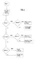
- With reference to
figure 1 , in a possible example of operative flow of the vehicle control system, when the system is started (Start) it gets the 3D data from the navigator (Reading vehicle situation), then it verifies if the expected road conditions are a Hill or a Descent or a Bend. In case of a Rise, or a Descent, the system also verifies if there is also a Bend at the same time. In any of these possible situations, the system controls the appropriate settings of the vehicle control systems (in the figure blocks respectively of: Rise + bend settings, or straight uphill road, or descent + bend settings, or straight downhill road, bend alone). Otherwise the system gets ready for a normal straight road. - The predictive system according to the invention works in parallel with the vehicle control system, and in case of a failure, or if a destination is not set, it is automatically disabled. However, the driver can always manually disable the system, since any driver's control intentionally prevails over these automatic interventions.
- In the following there is the description of a specific example of control performed when the detected conditions are a rise or a descent, for example having 6% road slope, travelling at a speed of 50 Km/h, or a bend, having a bending radius of 80 m and travelling at a speed of 60 Km/h.
- The control involves the following vehicle parts: engine, automatic transmission, hydraulic decelerator, active or pneumatic suspensions, ESP stability control system, braking system.
- The following controls will be performed on the engine.
- In case of a rise. Immediately before the rise condition takes place, the engine mapping is prepared: the torque/power curve can be dynamically changed, for example by choosing it among available alternatives of driving style: economy, sport, etc., paying attention to emissions. The choice is limited to the values allowed by the manufacturer.
- During the rise, an increase of the torque at low RPM is actuated, for example there is an automatic downshifting.
- In case of a descent. Immediately before the descent condition takes place, the engine is prepared to increase the engine brake, for example by controlling the variable geometry of the turbine, or the valve lift, and obtaining different levels of engine brake.
- During the descents, the engine is prepared to keep the vehicle speed constant by acting on the engine brake.
- In case of a bend. Immediately before the bend condition takes place, the RPM of the engine are reduced, if the engine speed is too high, and the vehicle decelerates. Namely, according to the bending radius, the system determines the appropriate speed.
- During the bend, a traction control with a control of the torque/RPM curve is performed, for example avoiding wheel slip because of an excessive power requirement. Even if the driver presses the accelerator pedal, the vehicle does not accelerate, in order to avoid providing a dangerous additional torque.
- The following controls will be performed on the transmission.
- In case of a rise. Immediately before the rise condition takes place, the automatic transmission is prepared to engage low gears.
- During the rise, low gears are engaged in order to increase the pickup.
- In case of a descent. Immediately before the descent condition takes place, the automatic transmission is prepared to keep the vehicle speed constant, with low gears engaged.
- In case of a bend. Immediately before the bend condition takes place, the transmission downshifts in advance.
- The following controls will be performed on the hydraulic decelerator (if present).
- In case of a descent. During the descent the release of the accelerator pedal is automatically performed according to the weight and to the slope, preferably using a decelerator which intervenes at progressive levels.
- In case of a bend. Immediately before the bend condition takes place, the hydraulic decelerator is activated if the speed is too high.
- In case of a rise the decelerator does not intervene.
- The following controls will be performed on the active suspensions (if present).
- In case of a bend. Immediately before the bend condition takes place, the suspensions are prepared for limiting the roll, by stiffening the suspensions in correspondence of the bend external side, and by softening the suspensions in correspondence of the bend internal side. During the bend, the roll limitation takes place.
- in case of a rise or of a descent, the suspension control may not be performed, since an auto-levelling control is already present. A levelling intervention, however, may be performed in case of pneumatic suspensions, in order to counterbalance the forward displacement of the barycentre during a descent, or backward displacement of the barycentre during a rise (pitch).
- The following controls will be performed on the ESP stability control system.
- In case of a bend. In case of a bend the ESP control is performed in order to oppose the yaw: the actual steering angle is conformed to the one required with the steering wheel.
- In case of a rise or of a descent, the stability control may not intervene.
- The following controls will be performed on the braking system.
- In case of a descent. Immediately before the descent condition takes place, the decelerator gets ready. During the descent, the speed is kept constant by means of the engine brake.
- In case of a bend. Immediately before the bend condition takes place, the ESP stability control system is enabled. During the bend, the traction control is required to the engine, adjusting the mapping.
- In case of a rise the braking system does not intervene. Compositions and overlapping of the effects between the two situation (descent or rise, and bend) are possible.
- This invention may advantageously be realized by means of a computer program, which comprises program code means performing one or more steps of said method, when said program is run on a computer. For this reason the scope of the present patent is meant to cover also said computer program and the computer-readable means that comprises a recorded message, such computer-readable means comprising the program code means for performing one or more steps of such method, when such program is run on a computer.
- It will be apparent to the person skilled in the art that other alternative and equivalent embodiments of the invention can be conceived and reduced to practice without departing from the scope of the invention.
- The advantages deriving from the use of this invention are evident.
- The advantages mainly relate to the reduction of the fuel consumption and of the consequent emissions, to the safety and driving comfort, and to avoid unexpected overloading of the mechanical parts.
- From the description set forth above it will be possible for the person skilled in the art to embody the invention with no need of describing further construction details.
Claims (13)
- Method for controlling vehicle components, comprising the steps of:- integrating a vehicle satellite navigation system with 3D navigation maps;- increasing the control functions of the vehicle components by means of a predictive control which exploits the predictive 3D data about the route provided by said satellite navigation system.
- Method for the vehicle control according to the claim 1, wherein said 3D predictive data about the route comprise latitude, longitude, altitude, slope and road bending radius.
- Method for the vehicle control according to the claim 1, wherein said vehicle components comprise one or more among transmission, preferably with automatic or robotized transmission, engine, brakes, possibly with ABS or EBS, active or pneumatic suspensions, hydraulic decelerator, (ESP) stability control system.
- Method for the vehicle control according to the claim 1, wherein said predictive control is performed in correspondence of uphill, downhill roads and/or bends, when the destination is set on said vehicle satellite navigation system.
- Method for the vehicle control according to the claim 4, wherein said predictive control is disabled in one of the following conditions:- in case of a detour from the route set on said vehicle satellite navigation system, while the latter recalculates the 3D predictive data of the new route;- during the temporary deactivation of the emissions of said 3D data.
- System for controlling vehicle components, comprising:- a vehicle satellite navigation system integrated with 3D navigation maps;- one or more electronic controller of the functioning of the vehicle components which perform a predictive control exploiting the predictive 3D data about the route provided by said satellite navigation system.
- System for the vehicle control according to the claim 6, wherein said 3D predictive data about the route comprise latitude, longitude, altitude, slope and road bending radius.
- System for the vehicle control according to the claim 6, wherein said vehicle components comprise one or more among transmission, preferably with automatic or robotized transmission, engine, brakes, possibly with ABS or EBS, active or pneumatic suspensions, hydraulic decelerator, (ESP) stability control system.
- System for the vehicle control according to the claim 6, wherein said one or more electronic controllers perform said predictive control in correspondence of uphill, downhill roads and/or bends, when the destination is set on said vehicle satellite navigation system.
- System for the vehicle control according to the claim 9, wherein said one or more electronic controllers disable predictive control in one of the following conditions:- in case of a detour from the route set on said vehicle satellite navigation system, while the latter recalculates the 3D predictive data of the new route;- during the temporary deactivation of the emissions of said 3D data.
- Usage of a vehicle satellite navigation integrated with 3D navigation maps in a system for controlling vehicle components, as in any or the claims from 6 to 10.
- Computer program comprising program code means suitable for performing the steps of any claim from 1 to 5, when such program is run on a computer.
- Computer-readable means comprising a recorded program, said computer-readable means comprising program code means suitable for performing the steps according to the claims from 1 to 5, when said program is run on a computer.
Priority Applications (2)
| Application Number | Priority Date | Filing Date | Title |
|---|---|---|---|
| EP09425458A EP2322903A1 (en) | 2009-11-13 | 2009-11-13 | Vehicle control system and method by using 3D navigation maps |
| PCT/EP2010/067363 WO2011058127A1 (en) | 2009-11-13 | 2010-11-12 | Vehicle control system and method by using 3d navigation maps |
Applications Claiming Priority (1)
| Application Number | Priority Date | Filing Date | Title |
|---|---|---|---|
| EP09425458A EP2322903A1 (en) | 2009-11-13 | 2009-11-13 | Vehicle control system and method by using 3D navigation maps |
Publications (1)
| Publication Number | Publication Date |
|---|---|
| EP2322903A1 true EP2322903A1 (en) | 2011-05-18 |
Family
ID=42010274
Family Applications (1)
| Application Number | Title | Priority Date | Filing Date |
|---|---|---|---|
| EP09425458A Withdrawn EP2322903A1 (en) | 2009-11-13 | 2009-11-13 | Vehicle control system and method by using 3D navigation maps |
Country Status (2)
| Country | Link |
|---|---|
| EP (1) | EP2322903A1 (en) |
| WO (1) | WO2011058127A1 (en) |
Cited By (6)
| Publication number | Priority date | Publication date | Assignee | Title |
|---|---|---|---|---|
| EP2589521A3 (en) * | 2011-11-02 | 2013-11-27 | Scania CV AB | Method and system for improving the operability of a motor vehicle |
| WO2014094934A1 (en) * | 2012-12-20 | 2014-06-26 | Daimler Ag | Method for determining a target curve incline of a motor vehicle during traveling of a curved roadway section |
| GB2518053A (en) * | 2014-08-06 | 2015-03-11 | Daimler Ag | Suspension system for a vehicle, in particular a commercial vehicle, as well as method for operating such a suspension system |
| US10160281B2 (en) | 2014-05-02 | 2018-12-25 | Ford Global Technologies, Llc | Road roughness preview with drive history |
| CN110758396A (en) * | 2019-10-31 | 2020-02-07 | 重庆长安汽车股份有限公司 | Vehicle low-speed control method and system based on dual-clutch transmission, storage medium and vehicle |
| CN111550551A (en) * | 2020-04-08 | 2020-08-18 | 杭州鸿泉物联网技术股份有限公司 | Fuel-saving auxiliary driving method, electronic equipment and storage medium |
Families Citing this family (2)
| Publication number | Priority date | Publication date | Assignee | Title |
|---|---|---|---|---|
| US9256576B2 (en) | 2012-11-08 | 2016-02-09 | Ford Global Technologies, Llc | Assisted direct start and active suspension integration control |
| CN104002816B (en) * | 2014-05-22 | 2018-04-27 | 厦门雅迅网络股份有限公司 | A kind of vehicle geographical environment, which excavates, perceives fuel saving method |
Citations (17)
| Publication number | Priority date | Publication date | Assignee | Title |
|---|---|---|---|---|
| EP0246655A1 (en) * | 1986-05-23 | 1987-11-25 | Nissan Motor Co., Ltd. | Actively controlled automotive suspension system with improved cornering characteristics |
| EP0345816A2 (en) * | 1988-06-10 | 1989-12-13 | Nissan Motor Co., Ltd. | Anti-rolling control for actively controlled automotive suspension system with enhanced rolling detecting ability |
| DE4003493A1 (en) * | 1990-02-06 | 1991-08-08 | Daimler Benz Ag | Hydro-pneumatic suspension for vehicle |
| JPH05345509A (en) * | 1992-06-15 | 1993-12-27 | Oki Electric Ind Co Ltd | Suspension controller |
| US5432700A (en) * | 1992-12-21 | 1995-07-11 | Ford Motor Company | Adaptive active vehicle suspension system |
| US5832400A (en) | 1994-09-05 | 1998-11-03 | Nissan Motor Co.., Ltd. | Controlling vehicular driving force in anticipation of road situation on which vehicle is to run utilizing vehicular navigation system |
| US6116618A (en) * | 1997-12-26 | 2000-09-12 | Toyota Jidosha Kabushiki Kaisha | Vehicular slope determination apparatus and vehicle height adjust control apparatus and vehicle height adjust control apparatus and method using the same |
| DE10007357A1 (en) * | 2000-02-18 | 2001-08-23 | Volkswagen Ag | Running gear regulation device for motor vehicle acquires road information from processing system containing navigation system, sets up running gear or its parts before traveling road section |
| EP1138530A2 (en) * | 2000-03-27 | 2001-10-04 | Bose Corporation | Surface vehicle vertical trajectory planning |
| US6314347B1 (en) * | 1999-05-20 | 2001-11-06 | Nissan Motor Co., Ltd. | Driving control apparatus of hybrid vehicle and method thereof |
| DE10141805A1 (en) * | 2000-09-23 | 2002-05-02 | Martin Krais | Determination of optimum routes or speeds for land, sea or air based craft or vehicles using a GPS positioning system so that safety and economy are optimized by taking into account the route to be followed and other craft |
| WO2003078185A1 (en) * | 2002-03-15 | 2003-09-25 | Adam Zadok | Steering controlled anti-roll automobile suspension |
| US6697717B2 (en) * | 2001-09-28 | 2004-02-24 | Pioneer Corporation | Hybrid car |
| DE102005051539A1 (en) | 2004-10-29 | 2006-09-21 | Continental Teves Ag & Co. Ohg | Method for increasing the driving safety and / or the comfort of a motor vehicle |
| DE102006036310A1 (en) | 2005-08-05 | 2007-02-08 | Aisin AW Co., Ltd., Anjo | navigation system |
| DE102007029359A1 (en) * | 2006-06-30 | 2008-01-03 | Denso Corp., Kariya | Control information storing device for vehicle, has information memory storing movement position of vehicle based on current position, and storing control starting point, which is detected by control point detecting unit |
| EP1927822A1 (en) * | 2006-12-01 | 2008-06-04 | Audi Ag | Method for controlling an operational or functional component of a motor vehicle on the basis of positional data received from a navigation system |
-
2009
- 2009-11-13 EP EP09425458A patent/EP2322903A1/en not_active Withdrawn
-
2010
- 2010-11-12 WO PCT/EP2010/067363 patent/WO2011058127A1/en active Application Filing
Patent Citations (17)
| Publication number | Priority date | Publication date | Assignee | Title |
|---|---|---|---|---|
| EP0246655A1 (en) * | 1986-05-23 | 1987-11-25 | Nissan Motor Co., Ltd. | Actively controlled automotive suspension system with improved cornering characteristics |
| EP0345816A2 (en) * | 1988-06-10 | 1989-12-13 | Nissan Motor Co., Ltd. | Anti-rolling control for actively controlled automotive suspension system with enhanced rolling detecting ability |
| DE4003493A1 (en) * | 1990-02-06 | 1991-08-08 | Daimler Benz Ag | Hydro-pneumatic suspension for vehicle |
| JPH05345509A (en) * | 1992-06-15 | 1993-12-27 | Oki Electric Ind Co Ltd | Suspension controller |
| US5432700A (en) * | 1992-12-21 | 1995-07-11 | Ford Motor Company | Adaptive active vehicle suspension system |
| US5832400A (en) | 1994-09-05 | 1998-11-03 | Nissan Motor Co.., Ltd. | Controlling vehicular driving force in anticipation of road situation on which vehicle is to run utilizing vehicular navigation system |
| US6116618A (en) * | 1997-12-26 | 2000-09-12 | Toyota Jidosha Kabushiki Kaisha | Vehicular slope determination apparatus and vehicle height adjust control apparatus and vehicle height adjust control apparatus and method using the same |
| US6314347B1 (en) * | 1999-05-20 | 2001-11-06 | Nissan Motor Co., Ltd. | Driving control apparatus of hybrid vehicle and method thereof |
| DE10007357A1 (en) * | 2000-02-18 | 2001-08-23 | Volkswagen Ag | Running gear regulation device for motor vehicle acquires road information from processing system containing navigation system, sets up running gear or its parts before traveling road section |
| EP1138530A2 (en) * | 2000-03-27 | 2001-10-04 | Bose Corporation | Surface vehicle vertical trajectory planning |
| DE10141805A1 (en) * | 2000-09-23 | 2002-05-02 | Martin Krais | Determination of optimum routes or speeds for land, sea or air based craft or vehicles using a GPS positioning system so that safety and economy are optimized by taking into account the route to be followed and other craft |
| US6697717B2 (en) * | 2001-09-28 | 2004-02-24 | Pioneer Corporation | Hybrid car |
| WO2003078185A1 (en) * | 2002-03-15 | 2003-09-25 | Adam Zadok | Steering controlled anti-roll automobile suspension |
| DE102005051539A1 (en) | 2004-10-29 | 2006-09-21 | Continental Teves Ag & Co. Ohg | Method for increasing the driving safety and / or the comfort of a motor vehicle |
| DE102006036310A1 (en) | 2005-08-05 | 2007-02-08 | Aisin AW Co., Ltd., Anjo | navigation system |
| DE102007029359A1 (en) * | 2006-06-30 | 2008-01-03 | Denso Corp., Kariya | Control information storing device for vehicle, has information memory storing movement position of vehicle based on current position, and storing control starting point, which is detected by control point detecting unit |
| EP1927822A1 (en) * | 2006-12-01 | 2008-06-04 | Audi Ag | Method for controlling an operational or functional component of a motor vehicle on the basis of positional data received from a navigation system |
Non-Patent Citations (1)
| Title |
|---|
| FAN YU ET AL: "Integrated Vehicle Dynamics Control â state-of-the art review", VEHICLE POWER AND PROPULSION CONFERENCE, 2008. VPPC '08. IEEE, IEEE, PISCATAWAY, NJ, USA, 3 September 2008 (2008-09-03), pages 1 - 6, XP031363489, ISBN: 978-1-4244-1848-0, DOI: 10.1109/VPPC.2008.4677809 * |
Cited By (10)
| Publication number | Priority date | Publication date | Assignee | Title |
|---|---|---|---|---|
| EP2589521A3 (en) * | 2011-11-02 | 2013-11-27 | Scania CV AB | Method and system for improving the operability of a motor vehicle |
| WO2014094934A1 (en) * | 2012-12-20 | 2014-06-26 | Daimler Ag | Method for determining a target curve incline of a motor vehicle during traveling of a curved roadway section |
| US9694812B2 (en) | 2012-12-20 | 2017-07-04 | Daimler Ag | Method for determining a target curve incline of a motor vehicle during traveling of a curved roadway section |
| US10160281B2 (en) | 2014-05-02 | 2018-12-25 | Ford Global Technologies, Llc | Road roughness preview with drive history |
| RU2692290C2 (en) * | 2014-05-02 | 2019-06-24 | Форд Глобал Технолоджис, ЛЛК | Vehicle control system based on previous trips |
| GB2518053A (en) * | 2014-08-06 | 2015-03-11 | Daimler Ag | Suspension system for a vehicle, in particular a commercial vehicle, as well as method for operating such a suspension system |
| WO2016020030A1 (en) * | 2014-08-06 | 2016-02-11 | Daimler Ag | Suspension system for a vehicle, in particular a commercial vehicle, as well as method for operating such a suspension system |
| CN110758396A (en) * | 2019-10-31 | 2020-02-07 | 重庆长安汽车股份有限公司 | Vehicle low-speed control method and system based on dual-clutch transmission, storage medium and vehicle |
| CN111550551A (en) * | 2020-04-08 | 2020-08-18 | 杭州鸿泉物联网技术股份有限公司 | Fuel-saving auxiliary driving method, electronic equipment and storage medium |
| CN111550551B (en) * | 2020-04-08 | 2021-07-27 | 杭州鸿泉物联网技术股份有限公司 | Fuel-saving auxiliary driving method, electronic equipment and storage medium |
Also Published As
| Publication number | Publication date |
|---|---|
| WO2011058127A1 (en) | 2011-05-19 |
Similar Documents
| Publication | Publication Date | Title |
|---|---|---|
| EP2322903A1 (en) | Vehicle control system and method by using 3D navigation maps | |
| US8855874B2 (en) | Method and device for controlling a vehicle cruise control | |
| US8527163B2 (en) | Gearbox control device | |
| RU2493980C2 (en) | Method and module to determine reference speed magnitudes for vehicle control | |
| EP2218945B1 (en) | Identification method of the optimal gear for a transmission of a vehicle | |
| EP2507104B1 (en) | Method and system for controlling a vehicle cruise control | |
| JP5274482B2 (en) | Vehicle driving assistance method and apparatus | |
| US8095286B2 (en) | Method for controlling shifts in an automated gearshift transmission | |
| US20060279137A1 (en) | Method for optimizing a braking sequence | |
| JP4918115B2 (en) | Vehicle travel control device | |
| GB2525102A (en) | Vehicle speed control system | |
| WO2016152749A1 (en) | Travel control device, and travel control method | |
| KR20100072225A (en) | Device and method for determining a mapping of the torque transmitted by a clutch in an automobile and hill-start assistance system for an automobile equipped with such device | |
| JP2006213294A (en) | Brake control system | |
| JP2017521300A (en) | Control of multi-speed transmission of vehicle | |
| JP5747511B2 (en) | Coasting control device | |
| KR101214304B1 (en) | Device and method for controlling torque distribution for 4 wheel driving vehicle | |
| JP2007083750A (en) | Constant speed travel controller and constant speed travel control method | |
| US20230041291A1 (en) | A cruise control system and a method for controlling a powertrain | |
| KR20080007246A (en) | Method for controlling driving functions of a motor vehicle | |
| WO2012115579A9 (en) | Method and system for control of cruise control | |
| JP2008232391A (en) | Automatic shift control system | |
| CN103930325A (en) | Function for controlling the speed of a motor vehicle on a slope | |
| JP3933188B2 (en) | Vehicle control device | |
| JP2014000900A (en) | Vehicle control device |
Legal Events
| Date | Code | Title | Description |
|---|---|---|---|
| PUAI | Public reference made under article 153(3) epc to a published international application that has entered the european phase |
Free format text: ORIGINAL CODE: 0009012 |
|
| AK | Designated contracting states |
Kind code of ref document: A1 Designated state(s): AT BE BG CH CY CZ DE DK EE ES FI FR GB GR HR HU IE IS IT LI LT LU LV MC MK MT NL NO PL PT RO SE SI SK SM TR |
|
| AX | Request for extension of the european patent |
Extension state: AL BA RS |
|
| 17P | Request for examination filed |
Effective date: 20111116 |
|
| 17Q | First examination report despatched |
Effective date: 20120521 |
|
| STAA | Information on the status of an ep patent application or granted ep patent |
Free format text: STATUS: THE APPLICATION IS DEEMED TO BE WITHDRAWN |
|
| 18D | Application deemed to be withdrawn |
Effective date: 20180602 |