EP2322123A1 - Surgical device - Google Patents
Surgical device Download PDFInfo
- Publication number
- EP2322123A1 EP2322123A1 EP09014235A EP09014235A EP2322123A1 EP 2322123 A1 EP2322123 A1 EP 2322123A1 EP 09014235 A EP09014235 A EP 09014235A EP 09014235 A EP09014235 A EP 09014235A EP 2322123 A1 EP2322123 A1 EP 2322123A1
- Authority
- EP
- European Patent Office
- Prior art keywords
- tube
- surgical instrument
- instrument system
- optical fiber
- oct
- Prior art date
- Legal status (The legal status is an assumption and is not a legal conclusion. Google has not performed a legal analysis and makes no representation as to the accuracy of the status listed.)
- Withdrawn
Links
Images

Classifications
-
- A—HUMAN NECESSITIES
- A61—MEDICAL OR VETERINARY SCIENCE; HYGIENE
- A61F—FILTERS IMPLANTABLE INTO BLOOD VESSELS; PROSTHESES; DEVICES PROVIDING PATENCY TO, OR PREVENTING COLLAPSING OF, TUBULAR STRUCTURES OF THE BODY, e.g. STENTS; ORTHOPAEDIC, NURSING OR CONTRACEPTIVE DEVICES; FOMENTATION; TREATMENT OR PROTECTION OF EYES OR EARS; BANDAGES, DRESSINGS OR ABSORBENT PADS; FIRST-AID KITS
- A61F9/00—Methods or devices for treatment of the eyes; Devices for putting-in contact lenses; Devices to correct squinting; Apparatus to guide the blind; Protective devices for the eyes, carried on the body or in the hand
- A61F9/007—Methods or devices for eye surgery
- A61F9/00736—Instruments for removal of intra-ocular material or intra-ocular injection, e.g. cataract instruments
- A61F9/00745—Instruments for removal of intra-ocular material or intra-ocular injection, e.g. cataract instruments using mechanical vibrations, e.g. ultrasonic
-
- A—HUMAN NECESSITIES
- A61—MEDICAL OR VETERINARY SCIENCE; HYGIENE
- A61B—DIAGNOSIS; SURGERY; IDENTIFICATION
- A61B3/00—Apparatus for testing the eyes; Instruments for examining the eyes
- A61B3/10—Objective types, i.e. instruments for examining the eyes independent of the patients' perceptions or reactions
- A61B3/1005—Objective types, i.e. instruments for examining the eyes independent of the patients' perceptions or reactions for measuring distances inside the eye, e.g. thickness of the cornea
-
- A—HUMAN NECESSITIES
- A61—MEDICAL OR VETERINARY SCIENCE; HYGIENE
- A61B—DIAGNOSIS; SURGERY; IDENTIFICATION
- A61B3/00—Apparatus for testing the eyes; Instruments for examining the eyes
- A61B3/10—Objective types, i.e. instruments for examining the eyes independent of the patients' perceptions or reactions
- A61B3/102—Objective types, i.e. instruments for examining the eyes independent of the patients' perceptions or reactions for optical coherence tomography [OCT]
Definitions
- the invention relates to surgical devices and surgical methods in general.
- the invention relates to a surgical instrument system and a surgical method for performing cataract surgery.
- a phakoemulsification needle is inserted into the capsular bag of a patient's eye through the cornea and the anterior chamber. Ultrasonic energy is supplied to the needle to emulsify the crystal lens of the eye. Emulsified pieces of the crystal lens are aspirated by the needle, and viscoelastic fluid is supplied through the needle into the capsular bag.
- An intraocular lens (IOL) is inserted into the capsular bag after the crystal lens has been removed by such processing.
- a phakic intraocular lens is inserted into the anterior chamber of the eye or into the posterior chamber of the eye, without removing the crystal lens of the eye.
- an intraocular lens is implanted into the anterior chamber, the posterior chamber or the capsular bag
- an intraocular lens of a size suitable for a patients eye.
- Lens sizes for anterior chamber phakic intraocular lenses and for posterior chamber phakic intraocular lenses have commonly been estimated by adding 0.5 to 1.0 mm to the horizontal white-to-white corneal diameter.
- the white-to-white corneal diameter is not a reliable indicator for the angle diameter of the interior chamber and the sulcus diameter, also referred to as sulcus-to-sulcus diameter, of the posterior chamber.
- a method comprises: inserting an OCT probe into an interior of an eye; emitting an OCT measuring beam from the OCT probe located within the eye into plural directions; and receiving OCT measuring light scattered from various tissue structures of the eye with the OCT probe.
- the OCT probe is connected to an optical coherence tomography (OCT) apparatus for imaging body tissues. Since the OCT probe is located within the eye, high accuracy measurements of eye tissues can be performed. In particular, eye tissues located behind the iris can be imaged, and diameters of the sulcus and of the capsular bag can be precisely determined. Based on such determination, it is possible to select an intraocular lens from a stock of intraocular lenses having different sizes, and the selected intraocular lens can be inserted into the eye through a same incision in the cornea of the eye through which the OCT probe was inserted.
- OCT optical coherence tomography
- a hole is formed in the crystal lens of the eye, and the OCT probe is inserted into this hole to measure the diameter of the capsular bag from within the crystal lens.
- an intraocular lens can be selected from a stock of intraocular lenses having different sizes, and the selected intraocular lens can be inserted into the capsular bag after removal of the crystal lens.
- the optical probe is comprised by a surgical instrument system comprising: an OCT apparatus including an interferometer; an optical fiber coupled to the OCT apparatus and extending a probe arm of the interferometer; a hand tool comprising: hand piece, a tube extending away from the hand piece and having a distal end, wherein a distal portion of the optical fiber is received within the tube, a beam emitter coupled to the tip end of the optical fiber and configured to emit an OCT measuring beam into an emission direction; and an actuator configured to change the emission direction of the OCT measuring beam relative to the tip end of the tube.
- the surgeon can manipulate the hand tool by grasping the hand piece with one or two hands to insert the tube into the eye such that the distal end of the tube is positioned at a location suitable for performing the OCT measurement of the eye tissues.
- the OCT measurement is performed by directing the OCT measuring beam into different directions from the emitter.
- the emitter is rotated about an axis by 360° to obtain an OCT B-Scan of one plane.
- the beam emitter is then translated by a small amount in a direction of extension of the distal portion of the tube, and a next B-Scan is obtained in a next adjacent plane.
- This process is repeated to obtain a sufficiently high number of B-Scans to generate an image of a sufficient volume of the eye tissues allowing to determine the desired geometric values of the eye, such as the diameter of the capsular bag, the diameter of the sulcus or the diameter of the anterior chamber angle.
- the hand tool also provides the function of a phakoemulsificator.
- the hand tool may comprise an ultrasonic transducer to vibrate a tip end of the tube or of a needle extending adjacent to the tube.
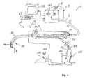
- Figure 1 is a schematic illustration of a surgical instrument system according to an embodiment.
- the surgical instrument system 1 comprises an optical coherence tomography (OCT) apparatus 3 including an optical interferometer received in a housing 5 and not shown in detail in figure 1 .
- the interferometer includes a reference arm and a probe arm provided and extended by an optical fiber 7.
- the optical fiber comprises a fiber core for carrying the OCT measuring light.
- the fiber 7 extends through a hand piece 9 of a hand tool manipulated by a surgeon.
- the hand tool comprises a tube 13 extending away from the hand piece 9, wherein the optical fiber 7 is received in and extends through the tube 13 towards a distal end portion 15 of the tube.
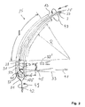
- FIG. 2 is a more detailed illustration of the distal end portion 15 of the tube 13.
- the distal end portion 15 of the tube 13 comprises a curved portion extending over a length 1 of more than 5 mm.
- Other exemplary values of the length 1 are 7 mm, 9 mm and 11 mm.
- a total length of the tube from the hand piece 9 to a tip end 21 thereof can be in a range from 10 mm to 50 mm.
- the curved portion may have a radius of curvature R within a range from 6 mm to 15 mm.
- Other exemplary values of the curvature range are 8 mm to 12 mm.
- the radius of curvature may be constant over the length 1, or the radius of curvature can vary over the length 1.
- the tube 13 can be made of metal or of a plastic material providing a suitable rigidity to maintain its shape under usage.
- a portion of the tube 13 close to its tip end 21 is made of a transparent material 23, such as glass or transparent plastic material.
- a fiber core 25 and a fiber cladding 27 of the fiber 7 extend through the distal portion 15 of the tube 13 towards its tip end 21.
- a tip end 29 of the fiber is coupled to a gradient index (GRIN) lens 31, which expands OCT measuring light supplied through the fiber 7 from the OCT apparatus 3 to shape a measuring beam 33 emitted from a front end 35 of the GRIN lens 31.
- a reflecting prism 37 is mounted to the front end 35 of the GRIN lens 31 and reflects the measuring beam such that is emitted in a direction 41 transverse to a direction of extension 42 of the distal end portion of the tube.
- An angle formed between the directions 41 and 42 can be 90° or greater, such as 100° or 120°, or smaller, such as 80° or 70°.
- the GRIN lens 31 is configured such that a beam waist 45 of the OCT measuring beam 33 is formed at a distance d of about 6 mm away from the tube 13. Other exemplary values of the distance d are about 4 mm, about 7 mm and about 9 mm. It is also possible that the beam 33 emitted from the GRIN lens 31 is a collimated parallel beam.
- the OCT apparatus comprises an actuator, such as a motor, to rotate the fiber 7 about its longitudinal axis as represented by an arrow 47 in figure 2 .
- an actuator such as a motor
- the GRIN lens 31 and prism 37 rotate about an axis oriented in direction 42 as indicated by an arrow 49 in figure 2 .
- the actuator for rotating the fiber 7 can be located in the housing 5 or the hand piece 9. Background information with respect to OCT apparatuses including a rotating fiber can be obtained from US 6,134,003 , the full disclosure of which is incorporated herein by reference.
- the OCT measuring beam 33 Due to the rotation of the beam emitter formed by the GRIN lens and prism 37, the OCT measuring beam 33 also rotates about the tip end portion of the tube 13. While rotating the fiber 7 about 360°, the OCT apparatus 3 records one OCT B-Scan.
- the hand tool 11 comprises an actuator, such as pair of rollers 51 driven by a motor controlled by the OCT apparatus 3 to displace the fiber 7 within the tube 13 in a longitudinal direction thereof.
- Figure 2 represents an OCT measuring beam 33' in broken lines which is emitted from the distal end portion of the tube 13 when the actuator 51 has retracted the fiber 7 by an amount f of e.g. 3 mm relative to the position indicated in full lines in figure 2 .
- the OCT apparatus 3 can systematically scan a volume around the tip end 21 of the tube 13 and perform OCT imaging of that volume. Both the rotation and the displacement of the fiber can be carried out at constant velocities such that measuring data can be associated to with coordinates of tissue structures based on measuring times. It is, however, possible to allow for known non-constant rotational velocities and non-constant velocities of longitudinal movement if the data analysis is carried out with taking the velocities into account.
- the scanning can be started by the surgeon by pressing, for example, a button 57 mounted on a front panel of the housing 5.
- a representation of the recorded OCT image of the OCT scan can be displayed, for example, on a monitor 59.
- the surgeon can identify certain features in the image and perform measurements, such as distances measurements using, for example by using a mouse 61 or a keyboard 63, to move a cross-hair cursor or other pointer between portions of the image and features within the image and calculate distances between different features in the image.
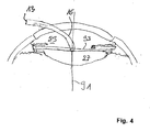
- FIG. 3 shows an anterior portion 71 of a human eye 73 including a cornea 75, limbus 77, iris 79, anterior chamber 89, anterior chamber angle 81, posterior chamber 82, sulcus 83 and capsular bag 85 including a crystal lens 87.
- the distal end portion 15 of the tube 13 of the hand tool 11 is inserted through an incision in the cornea such that the tip end 21 of the tube 13 and beam emitter 31, 35 are positioned within the anterior chamber 89 of the eye 73.
- the distal end of the tube 13 is positioned close to a main axis 91 of the eye 73 and oriented such that the direction 42 is substantially parallel to the main axis 91.
- an OCT volume scan is performed as illustrated above.
- the volume scan includes various tissues of the eye 73 and in particular of the anterior chamber angle 81.
- a diameter of the anterior chamber angle 83 can be determined by the surgeon by interpreting and analyzing the recorded OCT images displayed on the monitor 59. Based on this determination of the angle diameter, the surgeon may select a suitable phakic intraocular lens from a stock of lenses having different diameters. The selected lens can be inserted into the anterior chamber through the same incision through with the tube 13 was previously inserted.
- Figure 4 illustrates a further embodiment of the method.
- the method illustrated in figure 5 is similar to the method illustrated with reference to figure 3 above.
- the tip end 21 of the tube 13 is inserted into the posterior chamber 82 of the eye 73 such that it is positioned closer to the crystal lens 87 such that the beam 33 emitted from the distal end 21 of the tube 13 reaches the sulcus 81.
- By performing a volume scan with such positioning of the tip end of the tube 13 it is possible to image relevant portions of the sulcus 81 to be able to determine the sulcus diameter, also referred to as sulcus-to-sulcus diameter.
- the surgeon may select a phakic intraocular lens of a suitable size from a stock of lenses having different sizes. The selected lens can be inserted into the posterior chamber through the same incision through which the tube 13 was inserted.
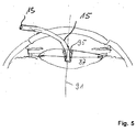
- Figure 5 illustrates a further embodiment of an OCT measurement.
- the tip end 21 of the tube 13 is positioned within the crystal lens 87 after an aperture or hole 95 has been formed in the lens 87 by some suitable method, such as phakoemulsification.
- the tube 13 is positioned such that the tip end substantially coincides with an axis 91 of the lens and is oriented substantially parallel thereto.
- a OCT volume scan with such configuration of the tube 13 records an image of the capsular bag from which the surgeon can determine the diameter of the capsular bag 85 to select a suitable intraocular lens from a stock of lenses having different diameters.
- the tube can be retracted from the eye 73, and the crystal lens 87 can be removed by phakoemulsification, for example. Thereafter, the surgeon can insert the selected intraocular lens into the capsular bag 85 through the same incision through which the tube 13 was previously inserted.
- the actuator 51 can be controlled to withdraw the fiber 7 from within the tube 13 to a sufficient extend.
- the tip end of the fiber can be positioned within the hand piece 9 after such withdrawal.
- This operation can be controlled by a button 101 mounted on the front panel of the housing 5 or some other input device, for example via the keyboard 63 or the mouse 61.
- the hand tool 11 can be operated as a phakoemulsificator.
- the hand tool comprises an ultrasonic transducer 103 coupled to the tube 13 such that the tip end of the tube starts vibrating at a high frequency.
- the tip end 21 of the tube carries a knife portion or sharp edge 105 suitable to cut emulsify body tissues, such as the crystal lens.
- the surgical instrument system further comprises a supply 107 of viscoelastic fluid which is pumped into the tube 13 via a connecting tube 109.
- the system 1 comprises a suction apparatus 111 connected to the tube 13 via a connecting tube 113.
- a foot paddle 115 which can be moved in a direction indicated by an arrow 117 in figure 1 , or other input device can be used by the surgeon to operate the ultrasonic transducer 103, liquid supply 107 and suction apparatus 111 to perform phakoemulsification.
- the hole 95 in the crystal lens 87 shown in figure 5 can be formed using the hand tool 11 which can be subsequently used to perform the OCT scan.
Abstract
The method can be performed using a surgical instrument system (1) comprising: an OCT apparatus (3) including an interferometer; an optical fiber (7) coupled to the OCT apparatus and extending a probe arm of the interferometer; a hand tool (11) comprising a hand piece (9), a tube (13) extending away from the hand piece and having a distal end (21), wherein a distal portion of the optical fiber is received within the tube, a beam emitter coupled to the tip end of the optical fiber and configured to emit an OCT measuring beam into an emission direction; and an actuator (51) configured to change the emission direction of the OCT measuring beam relative to the tip end of the tube.
Description
- The invention relates to surgical devices and surgical methods in general. In particular, the invention relates to a surgical instrument system and a surgical method for performing cataract surgery.
- In a cataract surgery, a phakoemulsification needle is inserted into the capsular bag of a patient's eye through the cornea and the anterior chamber. Ultrasonic energy is supplied to the needle to emulsify the crystal lens of the eye. Emulsified pieces of the crystal lens are aspirated by the needle, and viscoelastic fluid is supplied through the needle into the capsular bag. An intraocular lens (IOL) is inserted into the capsular bag after the crystal lens has been removed by such processing.
- In other eye surgery, a phakic intraocular lens (PIOL) is inserted into the anterior chamber of the eye or into the posterior chamber of the eye, without removing the crystal lens of the eye.
- To obtain an optimal result in such surgery, where an intraocular lens is implanted into the anterior chamber, the posterior chamber or the capsular bag, it is important to select an intraocular lens of a size suitable for a patients eye. Lens sizes for anterior chamber phakic intraocular lenses and for posterior chamber phakic intraocular lenses have commonly been estimated by adding 0.5 to 1.0 mm to the horizontal white-to-white corneal diameter. However, the white-to-white corneal diameter is not a reliable indicator for the angle diameter of the interior chamber and the sulcus diameter, also referred to as sulcus-to-sulcus diameter, of the posterior chamber. In particular, it is difficult to determine the sulcus diameter and the diameter of the capsular bag from outside of the eye since the iris prevents optical measurements of the corresponding tissue portions of the eye.
- It is desirable to provide methods and systems suitable for measuring geometries of eye tissues.
- According to embodiments of the invention, a method comprises: inserting an OCT probe into an interior of an eye; emitting an OCT measuring beam from the OCT probe located within the eye into plural directions; and receiving OCT measuring light scattered from various tissue structures of the eye with the OCT probe.
- The OCT probe is connected to an optical coherence tomography (OCT) apparatus for imaging body tissues. Since the OCT probe is located within the eye, high accuracy measurements of eye tissues can be performed. In particular, eye tissues located behind the iris can be imaged, and diameters of the sulcus and of the capsular bag can be precisely determined. Based on such determination, it is possible to select an intraocular lens from a stock of intraocular lenses having different sizes, and the selected intraocular lens can be inserted into the eye through a same incision in the cornea of the eye through which the OCT probe was inserted.
- According to embodiments of the invention, a hole is formed in the crystal lens of the eye, and the OCT probe is inserted into this hole to measure the diameter of the capsular bag from within the crystal lens. Again, an intraocular lens can be selected from a stock of intraocular lenses having different sizes, and the selected intraocular lens can be inserted into the capsular bag after removal of the crystal lens.
- According to embodiments of the invention, the optical probe is comprised by a surgical instrument system comprising: an OCT apparatus including an interferometer; an optical fiber coupled to the OCT apparatus and extending a probe arm of the interferometer; a hand tool comprising: hand piece, a tube extending away from the hand piece and having a distal end, wherein a distal portion of the optical fiber is received within the tube, a beam emitter coupled to the tip end of the optical fiber and configured to emit an OCT measuring beam into an emission direction; and an actuator configured to change the emission direction of the OCT measuring beam relative to the tip end of the tube.
- The surgeon can manipulate the hand tool by grasping the hand piece with one or two hands to insert the tube into the eye such that the distal end of the tube is positioned at a location suitable for performing the OCT measurement of the eye tissues. The OCT measurement is performed by directing the OCT measuring beam into different directions from the emitter.
- According to exemplary embodiments, the emitter is rotated about an axis by 360° to obtain an OCT B-Scan of one plane. The beam emitter is then translated by a small amount in a direction of extension of the distal portion of the tube, and a next B-Scan is obtained in a next adjacent plane. This process is repeated to obtain a sufficiently high number of B-Scans to generate an image of a sufficient volume of the eye tissues allowing to determine the desired geometric values of the eye, such as the diameter of the capsular bag, the diameter of the sulcus or the diameter of the anterior chamber angle.
- According to exemplary embodiments, the hand tool also provides the function of a phakoemulsificator. For this purpose, the hand tool may comprise an ultrasonic transducer to vibrate a tip end of the tube or of a needle extending adjacent to the tube.
- The foregoing as well as other advantages features of the invention should become more apparent from the following detailed description of exemplary embodiments of the invention with reference to the accompanying drawings.
- Figure 1
- is a schematic illustration of a surgical instrument system according to an embodiment of the invention;
- Figure 2
- is a schematic illustration of a detail of the system shown in
figure 1 ; - Figure 3
- is an illustration of a method of performing an OCT measurement of an anterior chamber of an eye;
- Figure 4
- is an illustration of a method of performing an OCT measurement of a posterior chamber of an eye; and
- Figure 5
- is an illustration of a method of performing an OCT measurement of a capsular bag of an eye
-
Figure 1 is a schematic illustration of a surgical instrument system according to an embodiment. - The
surgical instrument system 1 comprises an optical coherence tomography (OCT) apparatus 3 including an optical interferometer received in ahousing 5 and not shown in detail infigure 1 . The interferometer includes a reference arm and a probe arm provided and extended by anoptical fiber 7. The optical fiber comprises a fiber core for carrying the OCT measuring light. Thefiber 7 extends through a hand piece 9 of a hand tool manipulated by a surgeon. The hand tool comprises atube 13 extending away from the hand piece 9, wherein theoptical fiber 7 is received in and extends through thetube 13 towards adistal end portion 15 of the tube. -
Figure 2 is a more detailed illustration of thedistal end portion 15 of thetube 13. Thedistal end portion 15 of thetube 13 comprises a curved portion extending over alength 1 of more than 5 mm. Other exemplary values of thelength 1 are 7 mm, 9 mm and 11 mm. A total length of the tube from the hand piece 9 to atip end 21 thereof can be in a range from 10 mm to 50 mm. The curved portion may have a radius of curvature R within a range from 6 mm to 15 mm. Other exemplary values of the curvature range are 8 mm to 12 mm. The radius of curvature may be constant over thelength 1, or the radius of curvature can vary over thelength 1. - The
tube 13 can be made of metal or of a plastic material providing a suitable rigidity to maintain its shape under usage. In the illustrated embodiment, a portion of thetube 13 close to itstip end 21 is made of atransparent material 23, such as glass or transparent plastic material. - A
fiber core 25 and afiber cladding 27 of thefiber 7 extend through thedistal portion 15 of thetube 13 towards itstip end 21. - A
tip end 29 of the fiber is coupled to a gradient index (GRIN)lens 31, which expands OCT measuring light supplied through thefiber 7 from the OCT apparatus 3 to shape ameasuring beam 33 emitted from afront end 35 of theGRIN lens 31. A reflectingprism 37 is mounted to thefront end 35 of theGRIN lens 31 and reflects the measuring beam such that is emitted in adirection 41 transverse to a direction ofextension 42 of the distal end portion of the tube. An angle formed between thedirections - The
GRIN lens 31 is configured such that abeam waist 45 of theOCT measuring beam 33 is formed at a distance d of about 6 mm away from thetube 13. Other exemplary values of the distance d are about 4 mm, about 7 mm and about 9 mm. It is also possible that thebeam 33 emitted from theGRIN lens 31 is a collimated parallel beam. - The OCT apparatus comprises an actuator, such as a motor, to rotate the
fiber 7 about its longitudinal axis as represented by anarrow 47 infigure 2 . As a consequence, theGRIN lens 31 andprism 37 rotate about an axis oriented indirection 42 as indicated by anarrow 49 infigure 2 . The actuator for rotating thefiber 7 can be located in thehousing 5 or the hand piece 9. Background information with respect to OCT apparatuses including a rotating fiber can be obtained fromUS 6,134,003 , the full disclosure of which is incorporated herein by reference. - Due to the rotation of the beam emitter formed by the GRIN lens and
prism 37, theOCT measuring beam 33 also rotates about the tip end portion of thetube 13. While rotating thefiber 7 about 360°, the OCT apparatus 3 records one OCT B-Scan. - The
hand tool 11 comprises an actuator, such as pair ofrollers 51 driven by a motor controlled by the OCT apparatus 3 to displace thefiber 7 within thetube 13 in a longitudinal direction thereof.Figure 2 represents an OCT measuring beam 33' in broken lines which is emitted from the distal end portion of thetube 13 when theactuator 51 has retracted thefiber 7 by an amount f of e.g. 3 mm relative to the position indicated in full lines infigure 2 . - By rotating the
fiber 7 about its longitudinal axis and displacing thefiber 7 in its longitudinal direction, the OCT apparatus 3 can systematically scan a volume around thetip end 21 of thetube 13 and perform OCT imaging of that volume. Both the rotation and the displacement of the fiber can be carried out at constant velocities such that measuring data can be associated to with coordinates of tissue structures based on measuring times. It is, however, possible to allow for known non-constant rotational velocities and non-constant velocities of longitudinal movement if the data analysis is carried out with taking the velocities into account. - The scanning can be started by the surgeon by pressing, for example, a button 57 mounted on a front panel of the
housing 5. A representation of the recorded OCT image of the OCT scan can be displayed, for example, on amonitor 59. Moreover, the surgeon can identify certain features in the image and perform measurements, such as distances measurements using, for example by using amouse 61 or akeyboard 63, to move a cross-hair cursor or other pointer between portions of the image and features within the image and calculate distances between different features in the image. - An embodiment of an OCT measuring method which can be performed using the
system 1 is illustrated with reference tofigure 3. Figure 3 shows ananterior portion 71 of a human eye 73 including acornea 75,limbus 77,iris 79,anterior chamber 89, anterior chamber angle 81,posterior chamber 82,sulcus 83 andcapsular bag 85 including acrystal lens 87. Thedistal end portion 15 of thetube 13 of thehand tool 11 is inserted through an incision in the cornea such that thetip end 21 of thetube 13 andbeam emitter anterior chamber 89 of the eye 73. In particular, the distal end of thetube 13 is positioned close to amain axis 91 of the eye 73 and oriented such that thedirection 42 is substantially parallel to themain axis 91. With such position of thehand tool 11, an OCT volume scan is performed as illustrated above. The volume scan includes various tissues of the eye 73 and in particular of the anterior chamber angle 81. A diameter of theanterior chamber angle 83 can be determined by the surgeon by interpreting and analyzing the recorded OCT images displayed on themonitor 59. Based on this determination of the angle diameter, the surgeon may select a suitable phakic intraocular lens from a stock of lenses having different diameters. The selected lens can be inserted into the anterior chamber through the same incision through with thetube 13 was previously inserted. -
Figure 4 illustrates a further embodiment of the method. The method illustrated infigure 5 is similar to the method illustrated with reference tofigure 3 above. However, thetip end 21 of thetube 13 is inserted into theposterior chamber 82 of the eye 73 such that it is positioned closer to thecrystal lens 87 such that thebeam 33 emitted from thedistal end 21 of thetube 13 reaches the sulcus 81. For this purpose, it might be necessary to push the crystal lens a bit downward as illustrated infigure 4 . By performing a volume scan with such positioning of the tip end of thetube 13 it is possible to image relevant portions of the sulcus 81 to be able to determine the sulcus diameter, also referred to as sulcus-to-sulcus diameter. Again, the surgeon may select a phakic intraocular lens of a suitable size from a stock of lenses having different sizes. The selected lens can be inserted into the posterior chamber through the same incision through which thetube 13 was inserted. -
Figure 5 illustrates a further embodiment of an OCT measurement. In this embodiment, thetip end 21 of thetube 13 is positioned within thecrystal lens 87 after an aperture orhole 95 has been formed in thelens 87 by some suitable method, such as phakoemulsification. Thetube 13 is positioned such that the tip end substantially coincides with anaxis 91 of the lens and is oriented substantially parallel thereto. - A OCT volume scan with such configuration of the
tube 13 records an image of the capsular bag from which the surgeon can determine the diameter of thecapsular bag 85 to select a suitable intraocular lens from a stock of lenses having different diameters. - The tube can be retracted from the eye 73, and the
crystal lens 87 can be removed by phakoemulsification, for example. Thereafter, the surgeon can insert the selected intraocular lens into thecapsular bag 85 through the same incision through which thetube 13 was previously inserted. - The
actuator 51 can be controlled to withdraw thefiber 7 from within thetube 13 to a sufficient extend. For example, the tip end of the fiber can be positioned within the hand piece 9 after such withdrawal. This operation can be controlled by a button 101 mounted on the front panel of thehousing 5 or some other input device, for example via thekeyboard 63 or themouse 61. - After such removal of the fiber from within the
tube 13, thehand tool 11 can be operated as a phakoemulsificator. For this purpose, the hand tool comprises an ultrasonic transducer 103 coupled to thetube 13 such that the tip end of the tube starts vibrating at a high frequency. Thetip end 21 of the tube carries a knife portion orsharp edge 105 suitable to cut emulsify body tissues, such as the crystal lens. - The surgical instrument system further comprises a
supply 107 of viscoelastic fluid which is pumped into thetube 13 via a connectingtube 109. Further, thesystem 1 comprises a suction apparatus 111 connected to thetube 13 via a connectingtube 113. Afoot paddle 115 which can be moved in a direction indicated by anarrow 117 infigure 1 , or other input device can be used by the surgeon to operate the ultrasonic transducer 103,liquid supply 107 and suction apparatus 111 to perform phakoemulsification. For example, thehole 95 in thecrystal lens 87 shown infigure 5 can be formed using thehand tool 11 which can be subsequently used to perform the OCT scan. - The present application discloses in particular the following features:
- Features 1: A method comprising:
- inserting an OCT probe into an interior of an eye;
- emitting an OCT measuring beam from the OCT probe located within the eye into plural directions; and
- receiving OCT measuring light scattered from various tissue structures of the eye with the OCT probe.
- Features 2: The method according to
features 1, further comprising inserting an intraocular lens into the eye. - Features 3: The method according to
features 1 or 2, further comprising determining at least one of a diameter of an anterior chamber of the eye, a diameter of a posterior chamber of the eye and a diameter of a capsular bag of the eye based on the received OCT measuring light. - Features 4: The method according to
features 1, further comprising selecting an intraocular lens from a stock of intraocular lenses having different diameters based on the determined diameter, and inserting the selected intraocular lens into the eye. - Features 5: The method according to one of features 2 to 4, wherein the inserting comprises inserting the intraocular lens into one of the anterior chamber of the eye, the posterior chamber of the eye and the capsular bag of the eye.
- Features 6: The method according to one of features 2 to 5, further comprising retracting the OCT probe before inserting the intraocular lens.
- Features 7: The method according to one of features 2 to 6, further comprising generating an opening in a cornea of the eye and inserting the OCT probe through the opening in the cornea into the interior of the eye.
- Features 8: The method according to
features 7, further comprising inserting an intraocular lens into the eye through the opening. - Features 9: A method, in particular in features with one of
features 1 to 8, the method comprising:- forming a hole in a lens of an eye by removing a portion of the lens;
- inserting an OCT probe into the hole formed in the lens; emitting an OCT measuring beam from the OCT probe located within hole formed in the lens into plural directions; and receiving OCT measuring light scattered from various tissue structures of the eye with the OCT probe.
- Features 10: The method according to features 9, wherein the forming of the hole in the lens comprises phakoemulsification.
- Features 11: The method according to one of features 9 or 10, further comprising removing of the lens.
- Features 12: The method according to
features 11, wherein the removing of the lens comprises phakoemulsification. - Features 13: The method according to features 12, further comprising inserting an intraocular lens into the capsular bag of the eye.
- Features 14: The method according to one of features 9 to 13, further comprising determining a diameter of a capsular bag of the eye based on the received OCT measuring light.
- Features 15: The method according to features 14, further comprising selecting an intraocular lens from a stock of intraocular lenses having different diameters based on the determined diameter, and inserting the selected intraocular lens into the eye.
- Features 16: The method according to one of
features 1 to 15, wherein the OCT probe comprises a tube having a proximal end and a distal end, and an optical fiber extending through the tube, wherein the OCT measuring beam is emitted from the distal end of the tube. - Features 17. The method according to features 16, further comprising moving the optical fiber to direct the OCT measuring light into the different directions.
- Features 18: The method according to features 17, wherein the moving of the optical fiber comprises rotating the fiber about a longitudinal axis thereof.
- Features 19: The method according to features 17, wherein the moving of the optical fiber comprises bending a distal end of the optical fiber.
- Features 20: The method according to features 19, wherein the bending of the distal end of the optical fiber comprises oscillating a distal end portion of the optical fiber.
- Features 21: The method according to one of features 16 to 20, wherein the OCT measuring beam is emitted in a direction transverse to a direction of extension of a distal portion of the optical fiber.
- Features 22: The method according to one of features 16 to 21, wherein a GRIN lens is attached to the distal end of the fiber.
- Features 23: The method according to features 22, wherein the GRIN lens carries a reflecting surface directing the OCT measuring beam into a direction transverse to a direction of extension of the distal portion of the optical fiber.
- Features 24: The method according to one of features 16 to 23, wherein the inserting of the OCT probe into the interior of the eye comprises orienting the distal end of the tube such that it is oriented substantially parallel to a main axis of the eye.
- Features 25: The method according to one of features 16 to 24, wherein the inserting of the OCT probe into the interior of the eye comprises positioning the distal end of the tube such that it is located substantially on a main axis of the eye.
- Features 26: The method according to one of features 16 to 25, wherein the distal end portion of the tube is a curved portion.
- Features 27: The method according to features 26, wherein the curved portion has a same curvature over a length greater than at least one of 5 mm, 7 mm, 9 mm and 11 mm.
- Features 28: The method according to
features 26 or 27, wherein the curved portion has a radius of curvature in a range from 6 mm to 15 mm, and in particular in a range from 8 mm to 12 mm. - Features 29: The method according to one of features 16 to 28, wherein the tube is integrated with a phacoemulsificator.
- Features 30: The method according to
features 29, further comprising retracting the optical fiber from within the tube before performing phakoemulsification. - While certain exemplary embodiments are disclosed herein, alternatives, modifications and variations will be apparent to those skilled in the art. Accordingly, the exemplary embodiments set forth herein are intended to be illustrative and not limiting in any way. Various changes may be made without departing from the spirit and scope of the present disclosure.
Claims (15)
- A surgical instrument system comprising:an OCT apparatus including an interferometer;an optical fiber coupled to the OCT apparatus andextending a probe arm of the interferometer;a hand tool comprising:hand piece,a tube extending away from the hand piece and having a distal end, wherein a distal portion of the optical fiber is received within the tube,a beam emitter coupled to the tip end of the optical fiber and configured to emit an OCT measuring beam into an emission direction; andan actuator configured to change the emission direction of the OCT measuring beam relative to the tip end of the tube.
- The surgical instrument system according to claim 1, wherein the actuator is configured to rotate the optical fiber about a longitudinal axis thereof.
- The surgical instrument system according to claim 1, wherein the actuator is configured to move the optical fiber in a longitudinal axis thereof relative to the tube.
- The surgical instrument system according to claim 1, wherein the actuator is configured to rotate the optical fiber about a longitudinal axis thereof and to move the optical fiber in the longitudinal axis relative to the tube.
- The surgical instrument system according to one of claims 1 to 4, wherein the distal end portion of the tube is a curved portion.
- The surgical instrument system according to claim 5, wherein the curved portion has a same curvature over a length greater than at least one of 5 mm, 7 mm, 9 mm and 11 mm.
- The surgical instrument system according to claim 5 or 6, wherein the curved portion has a radius of curvature in a range from 6 mm to 15 mm, and in particular in a range from 8 mm to 12 mm.
- The surgical instrument system according to one of claims 1 to 4, wherein the beam emitter comprises a GRIN lens.
- The surgical instrument system according to one of claims 1 to 8, wherein the beam emitter comprises a reflector.
- The surgical instrument system according to one of claims 1 to 9, wherein the beam emitter is configured to shape the OCT measuring beam such that it has a beam waist at a distance of greater than 4 mm and less than 9 mm from the emitter.
- The surgical instrument system according to one of claims 1 to 10, wherein the optical fiber is retractable from within the tube.
- The surgical instrument system according to one of claims 1 to 11, wherein the hand tool comprises a phacoemulsificator.
- The surgical instrument system according to one of claim 12, wherein phacoemulsificator comprises an ultrasonic transducer configured to vibrate the tip end of the tube.
- The surgical instrument system according to claim 13, wherein the tip end of the tube includes a needle.
- The surgical instrument system according to one of claims 12 to 14, wherein the phacoemulsificator comprises a fluid supply and/or an aspiration line.
Priority Applications (5)
| Application Number | Priority Date | Filing Date | Title |
|---|---|---|---|
| EP09014235A EP2322123A1 (en) | 2009-11-13 | 2009-11-13 | Surgical device |
| PCT/EP2010/006935 WO2011057814A1 (en) | 2009-11-13 | 2010-11-15 | Surgical device |
| DE112010004376T DE112010004376T5 (en) | 2009-11-13 | 2010-11-15 | Device for surgery and surgical procedure |
| US13/470,680 US9913752B2 (en) | 2009-11-13 | 2012-05-14 | Surgical device and surgical method |
| US15/902,323 US20180177637A1 (en) | 2009-11-13 | 2018-02-22 | Surgical device and surgical method |
Applications Claiming Priority (1)
| Application Number | Priority Date | Filing Date | Title |
|---|---|---|---|
| EP09014235A EP2322123A1 (en) | 2009-11-13 | 2009-11-13 | Surgical device |
Publications (1)
| Publication Number | Publication Date |
|---|---|
| EP2322123A1 true EP2322123A1 (en) | 2011-05-18 |
Family
ID=41600411
Family Applications (1)
| Application Number | Title | Priority Date | Filing Date |
|---|---|---|---|
| EP09014235A Withdrawn EP2322123A1 (en) | 2009-11-13 | 2009-11-13 | Surgical device |
Country Status (4)
| Country | Link |
|---|---|
| US (2) | US9913752B2 (en) |
| EP (1) | EP2322123A1 (en) |
| DE (1) | DE112010004376T5 (en) |
| WO (1) | WO2011057814A1 (en) |
Families Citing this family (14)
| Publication number | Priority date | Publication date | Assignee | Title |
|---|---|---|---|---|
| US8755114B1 (en) | 2013-06-14 | 2014-06-17 | Computer Power Supply, Inc. | Apparatus for aiding manual, mechanical alignment of optical equipment |
| US20150328047A1 (en) * | 2014-05-19 | 2015-11-19 | Francis Y. Falck, Jr. | Cataract Removal Tool |
| US20150351629A1 (en) * | 2014-06-06 | 2015-12-10 | Novartis Ag | Back reflection minimization for oct probes |
| NZ773833A (en) | 2015-03-16 | 2022-07-01 | Magic Leap Inc | Methods and systems for diagnosing and treating health ailments |
| US10624785B2 (en) | 2016-01-30 | 2020-04-21 | Carl Zeiss Meditec Cataract Technology Inc. | Devices and methods for ocular surgery |
| IL299497B2 (en) | 2016-04-08 | 2024-02-01 | Magic Leap Inc | Augmented reality systems and methods with variable focus lens elements |
| US10456002B2 (en) | 2016-12-22 | 2019-10-29 | Irobot Corporation | Cleaning bin for cleaning robot |
| AU2018225146A1 (en) | 2017-02-23 | 2019-08-29 | Magic Leap, Inc. | Display system with variable power reflector |
| EP4052686A1 (en) | 2017-05-04 | 2022-09-07 | Carl Zeiss Meditec Cataract Technology Inc. | Devices for ocular surgery |
| CN112702982B (en) | 2018-06-05 | 2023-12-19 | 卡尔蔡司白内障医疗技术公司 | Ophthalmic microsurgical tools, systems, and methods of use |
| US11241335B2 (en) | 2019-02-01 | 2022-02-08 | Carl Zeiss Meditec Cataract Technology Inc. | Ophthalmic cutting instruments having integrated aspiration pump |
| CA3140788A1 (en) | 2019-05-17 | 2020-11-26 | Carl Zeiss Meditec Cataract Technology Inc. | Ophthalmic cutting instruments having integrated aspiration pump |
| AU2020288110A1 (en) | 2019-06-07 | 2022-01-27 | Carl Zeiss Meditec Cataract Technology Inc. | Multi-stage trigger for ophthalmology cutting tool |
| US11883326B2 (en) | 2020-11-03 | 2024-01-30 | Johnson & Johnson Surgical Vision, Inc. | Phacoemulsification probe stroke length maximization system |
Citations (5)
| Publication number | Priority date | Publication date | Assignee | Title |
|---|---|---|---|---|
| US6134003A (en) | 1991-04-29 | 2000-10-17 | Massachusetts Institute Of Technology | Method and apparatus for performing optical measurements using a fiber optic imaging guidewire, catheter or endoscope |
| US6501551B1 (en) * | 1991-04-29 | 2002-12-31 | Massachusetts Institute Of Technology | Fiber optic imaging endoscope interferometer with at least one faraday rotator |
| US20030004412A1 (en) * | 1999-02-04 | 2003-01-02 | Izatt Joseph A. | Optical imaging device |
| US6564087B1 (en) * | 1991-04-29 | 2003-05-13 | Massachusetts Institute Of Technology | Fiber optic needle probes for optical coherence tomography imaging |
| US20090157062A1 (en) * | 2007-12-13 | 2009-06-18 | Christoph Hauger | Systems and methods for treating glaucoma and systems and methods for imaging a portion of an eye |
Family Cites Families (8)
| Publication number | Priority date | Publication date | Assignee | Title |
|---|---|---|---|---|
| US5651783A (en) * | 1995-12-20 | 1997-07-29 | Reynard; Michael | Fiber optic sleeve for surgical instruments |
| IL156831A0 (en) * | 2001-01-18 | 2004-02-08 | Univ California | Minimally invasive glaucoma surgical instrument and method |
| US6533750B2 (en) | 2001-01-23 | 2003-03-18 | Advanced Medical Optics | Conically shaped phaco tip |
| US7844321B2 (en) * | 2003-04-28 | 2010-11-30 | Board Of Regents, The University Of Texas System | Rotating catheter probe using a light-drive apparatus |
| US20050251116A1 (en) * | 2004-05-05 | 2005-11-10 | Minnow Medical, Llc | Imaging and eccentric atherosclerotic material laser remodeling and/or ablation catheter |
| US7993398B2 (en) | 2007-04-24 | 2011-08-09 | Abbott Medical Optics Inc. | Angle indicator for capsular bag size measurement |
| US8435248B2 (en) * | 2007-10-05 | 2013-05-07 | Wesley K. Herman | Probe tip and infusion sleeve for use with ophthalmological surgery |
| US10045882B2 (en) * | 2009-10-30 | 2018-08-14 | The Johns Hopkins University | Surgical instrument and systems with integrated optical sensor |
-
2009
- 2009-11-13 EP EP09014235A patent/EP2322123A1/en not_active Withdrawn
-
2010
- 2010-11-15 DE DE112010004376T patent/DE112010004376T5/en active Pending
- 2010-11-15 WO PCT/EP2010/006935 patent/WO2011057814A1/en active Application Filing
-
2012
- 2012-05-14 US US13/470,680 patent/US9913752B2/en active Active
-
2018
- 2018-02-22 US US15/902,323 patent/US20180177637A1/en not_active Abandoned
Patent Citations (5)
| Publication number | Priority date | Publication date | Assignee | Title |
|---|---|---|---|---|
| US6134003A (en) | 1991-04-29 | 2000-10-17 | Massachusetts Institute Of Technology | Method and apparatus for performing optical measurements using a fiber optic imaging guidewire, catheter or endoscope |
| US6501551B1 (en) * | 1991-04-29 | 2002-12-31 | Massachusetts Institute Of Technology | Fiber optic imaging endoscope interferometer with at least one faraday rotator |
| US6564087B1 (en) * | 1991-04-29 | 2003-05-13 | Massachusetts Institute Of Technology | Fiber optic needle probes for optical coherence tomography imaging |
| US20030004412A1 (en) * | 1999-02-04 | 2003-01-02 | Izatt Joseph A. | Optical imaging device |
| US20090157062A1 (en) * | 2007-12-13 | 2009-06-18 | Christoph Hauger | Systems and methods for treating glaucoma and systems and methods for imaging a portion of an eye |
Also Published As
| Publication number | Publication date |
|---|---|
| US20180177637A1 (en) | 2018-06-28 |
| US9913752B2 (en) | 2018-03-13 |
| US20120226267A1 (en) | 2012-09-06 |
| WO2011057814A1 (en) | 2011-05-19 |
| DE112010004376T5 (en) | 2012-11-29 |
Similar Documents
| Publication | Publication Date | Title |
|---|---|---|
| EP2322123A1 (en) | Surgical device | |
| AU2016262713B2 (en) | Balanced phacoemulsification tip | |
| US10383765B2 (en) | Apparatus and method for a global coordinate system for use in robotic surgery | |
| US10045882B2 (en) | Surgical instrument and systems with integrated optical sensor | |
| US9014788B2 (en) | Apparatus and method for real-time imaging and monitoring of an electrosurgical procedure | |
| JP5242410B2 (en) | Ophthalmological measurement system and method for determining ocular biometric data | |
| US20140194859A1 (en) | System and method of performing femtosecond laser accomodative capsulotomy | |
| US10682051B2 (en) | Surgical system having an OCT device | |
| US20140180133A1 (en) | Scanning endoscopic imaging probes and related methods | |
| EP4169465A1 (en) | System for measuring tilt in the crystalline lens for laser phaco fragmentation | |
| JP5677041B2 (en) | Ophthalmic equipment | |
| US10959612B2 (en) | Method for classifying the cataract of an eye | |
| JP5226908B1 (en) | Biopsy instrument | |
| CN115003209A (en) | Arrangement comprising an OCT apparatus for determining a 3D reconstruction of an object region volume, computer program and computer-implemented method for determining a 3D reconstruction of an object region volume | |
| WO2018193932A1 (en) | Information processing device, surgical tool, information processing method, and program | |
| EP3760145B1 (en) | Access devices and associated methods of production | |
| CN212261546U (en) | Knee joint unicondylar replacement operation shin bone platform size measurement ware | |
| JP2763585B2 (en) | Apparatus for determining anterior chamber depth of surgical eye and test lens apparatus used for determining the anterior chamber depth | |
| CN115884736A (en) | Control device, control method, program, and ophthalmic surgery system | |
| WO1992019159A1 (en) | Device for sampling tissue cells and method of guiding said device | |
| CN111529082A (en) | Knee joint unicondylar replacement operation shin bone platform size measurement ware | |
| Hauff et al. | Biometry with Mini A-Scan Instrument |
Legal Events
| Date | Code | Title | Description |
|---|---|---|---|
| PUAI | Public reference made under article 153(3) epc to a published international application that has entered the european phase |
Free format text: ORIGINAL CODE: 0009012 |
|
| AK | Designated contracting states |
Kind code of ref document: A1 Designated state(s): AT BE BG CH CY CZ DE DK EE ES FI FR GB GR HR HU IE IS IT LI LT LU LV MC MK MT NL NO PL PT RO SE SI SK SM TR |
|
| AX | Request for extension of the european patent |
Extension state: AL BA RS |
|
| RAP1 | Party data changed (applicant data changed or rights of an application transferred) |
Owner name: CARL ZEISS MEDITEC AG |
|
| STAA | Information on the status of an ep patent application or granted ep patent |
Free format text: STATUS: THE APPLICATION IS DEEMED TO BE WITHDRAWN |
|
| 18D | Application deemed to be withdrawn |
Effective date: 20111119 |