EP2320080A1 - Arrangement for cooling of an electrical generator - Google Patents
Arrangement for cooling of an electrical generator Download PDFInfo
- Publication number
- EP2320080A1 EP2320080A1 EP09013958A EP09013958A EP2320080A1 EP 2320080 A1 EP2320080 A1 EP 2320080A1 EP 09013958 A EP09013958 A EP 09013958A EP 09013958 A EP09013958 A EP 09013958A EP 2320080 A1 EP2320080 A1 EP 2320080A1
- Authority
- EP
- European Patent Office
- Prior art keywords
- cooling
- pipe
- stator
- arrangement according
- laminate plates
- Prior art date
- Legal status (The legal status is an assumption and is not a legal conclusion. Google has not performed a legal analysis and makes no representation as to the accuracy of the status listed.)
- Withdrawn
Links
Images


Classifications
-
- F—MECHANICAL ENGINEERING; LIGHTING; HEATING; WEAPONS; BLASTING
- F03—MACHINES OR ENGINES FOR LIQUIDS; WIND, SPRING, OR WEIGHT MOTORS; PRODUCING MECHANICAL POWER OR A REACTIVE PROPULSIVE THRUST, NOT OTHERWISE PROVIDED FOR
- F03D—WIND MOTORS
- F03D80/00—Details, components or accessories not provided for in groups F03D1/00 - F03D17/00
- F03D80/60—Cooling or heating of wind motors
-
- F—MECHANICAL ENGINEERING; LIGHTING; HEATING; WEAPONS; BLASTING
- F03—MACHINES OR ENGINES FOR LIQUIDS; WIND, SPRING, OR WEIGHT MOTORS; PRODUCING MECHANICAL POWER OR A REACTIVE PROPULSIVE THRUST, NOT OTHERWISE PROVIDED FOR
- F03D—WIND MOTORS
- F03D9/00—Adaptations of wind motors for special use; Combinations of wind motors with apparatus driven thereby; Wind motors specially adapted for installation in particular locations
- F03D9/20—Wind motors characterised by the driven apparatus
- F03D9/25—Wind motors characterised by the driven apparatus the apparatus being an electrical generator
-
- H—ELECTRICITY
- H02—GENERATION; CONVERSION OR DISTRIBUTION OF ELECTRIC POWER
- H02K—DYNAMO-ELECTRIC MACHINES
- H02K1/00—Details of the magnetic circuit
- H02K1/06—Details of the magnetic circuit characterised by the shape, form or construction
- H02K1/12—Stationary parts of the magnetic circuit
- H02K1/20—Stationary parts of the magnetic circuit with channels or ducts for flow of cooling medium
-
- H—ELECTRICITY
- H02—GENERATION; CONVERSION OR DISTRIBUTION OF ELECTRIC POWER
- H02K—DYNAMO-ELECTRIC MACHINES
- H02K9/00—Arrangements for cooling or ventilating
- H02K9/19—Arrangements for cooling or ventilating for machines with closed casing and closed-circuit cooling using a liquid cooling medium, e.g. oil
- H02K9/197—Arrangements for cooling or ventilating for machines with closed casing and closed-circuit cooling using a liquid cooling medium, e.g. oil in which the rotor or stator space is fluid-tight, e.g. to provide for different cooling media for rotor and stator
-
- F—MECHANICAL ENGINEERING; LIGHTING; HEATING; WEAPONS; BLASTING
- F05—INDEXING SCHEMES RELATING TO ENGINES OR PUMPS IN VARIOUS SUBCLASSES OF CLASSES F01-F04
- F05B—INDEXING SCHEME RELATING TO WIND, SPRING, WEIGHT, INERTIA OR LIKE MOTORS, TO MACHINES OR ENGINES FOR LIQUIDS COVERED BY SUBCLASSES F03B, F03D AND F03G
- F05B2260/00—Function
- F05B2260/20—Heat transfer, e.g. cooling
- F05B2260/201—Heat transfer, e.g. cooling by impingement of a fluid
-
- H—ELECTRICITY
- H02—GENERATION; CONVERSION OR DISTRIBUTION OF ELECTRIC POWER
- H02K—DYNAMO-ELECTRIC MACHINES
- H02K1/00—Details of the magnetic circuit
- H02K1/06—Details of the magnetic circuit characterised by the shape, form or construction
- H02K1/12—Stationary parts of the magnetic circuit
- H02K1/16—Stator cores with slots for windings
-
- H—ELECTRICITY
- H02—GENERATION; CONVERSION OR DISTRIBUTION OF ELECTRIC POWER
- H02K—DYNAMO-ELECTRIC MACHINES
- H02K2213/00—Specific aspects, not otherwise provided for and not covered by codes H02K2201/00 - H02K2211/00
- H02K2213/12—Machines characterised by the modularity of some components
-
- H—ELECTRICITY
- H02—GENERATION; CONVERSION OR DISTRIBUTION OF ELECTRIC POWER
- H02K—DYNAMO-ELECTRIC MACHINES
- H02K7/00—Arrangements for handling mechanical energy structurally associated with dynamo-electric machines, e.g. structural association with mechanical driving motors or auxiliary dynamo-electric machines
- H02K7/18—Structural association of electric generators with mechanical driving motors, e.g. with turbines
- H02K7/1807—Rotary generators
- H02K7/1823—Rotary generators structurally associated with turbines or similar engines
- H02K7/183—Rotary generators structurally associated with turbines or similar engines wherein the turbine is a wind turbine
- H02K7/1838—Generators mounted in a nacelle or similar structure of a horizontal axis wind turbine
-
- Y—GENERAL TAGGING OF NEW TECHNOLOGICAL DEVELOPMENTS; GENERAL TAGGING OF CROSS-SECTIONAL TECHNOLOGIES SPANNING OVER SEVERAL SECTIONS OF THE IPC; TECHNICAL SUBJECTS COVERED BY FORMER USPC CROSS-REFERENCE ART COLLECTIONS [XRACs] AND DIGESTS
- Y02—TECHNOLOGIES OR APPLICATIONS FOR MITIGATION OR ADAPTATION AGAINST CLIMATE CHANGE
- Y02E—REDUCTION OF GREENHOUSE GAS [GHG] EMISSIONS, RELATED TO ENERGY GENERATION, TRANSMISSION OR DISTRIBUTION
- Y02E10/00—Energy generation through renewable energy sources
- Y02E10/70—Wind energy
- Y02E10/72—Wind turbines with rotation axis in wind direction
-
- Y—GENERAL TAGGING OF NEW TECHNOLOGICAL DEVELOPMENTS; GENERAL TAGGING OF CROSS-SECTIONAL TECHNOLOGIES SPANNING OVER SEVERAL SECTIONS OF THE IPC; TECHNICAL SUBJECTS COVERED BY FORMER USPC CROSS-REFERENCE ART COLLECTIONS [XRACs] AND DIGESTS
- Y02—TECHNOLOGIES OR APPLICATIONS FOR MITIGATION OR ADAPTATION AGAINST CLIMATE CHANGE
- Y02T—CLIMATE CHANGE MITIGATION TECHNOLOGIES RELATED TO TRANSPORTATION
- Y02T50/00—Aeronautics or air transport
- Y02T50/60—Efficient propulsion technologies, e.g. for aircraft
Definitions
- the invention relates to an arrangement for cooling of an electrical generator, to be used in a wind-turbine preferably.
- Eddy currents contribute to the generation of heat. Eddy currents are generated when a conductor is exposed to a changing magnetic field due to a relative motion of the conductor and the magnetic field force. Eddy currents are also generated due to variations of the magnetic field over time.
- the eddy current loss may reach a significant level, especially for a large electrical machine like a direct drive generator in a wind turbine. Thus the efficiency of the rotor is reduced.
- a typical stator contains stacked laminate plates, which are made of metal.
- the laminate plates are punched out from a sheet of iron, for example.
- a number of laminate plates LP will be stacked, so the slots SL form channels CH within the stack of laminate plates LP.
- the channels CH support metal windings MW of a stator coil.
- Each metal winding MW is formed by a conductor CON, which is surrounded by a conductor-isolation CONI.
- Each slot SL shows a slot isolation lining SIL to insulate the metal windings MW.
- Another common method is to introduce a liquid or gaseous medium in hollow copper bars. These bars are installed below the windings of the stator coil or they are connected with the rear side of the stacked laminate plates by welding. The copper bars exceed the channels of the laminate plates.
- cooling pipes are exposed to the same electromagnetic fields as the coil-windings, thus voltages will be induced in the cooling pipes, which are made of metal.
- stator laminate made of iron, comprises C-shaped slots on the stator side, which points away from the rotor. Cooling tubes are inserted in said slots and the tubes are deformed to fit into the C-shaped channels.
- the drawback of this method is that the deformation of the cooling tubes may lead to small cracks in the tubes. These cracks may enlarge over time, for example due to corrosion, environmental influences or material characteristics. Thus the cracks will result in leaks later.
- the arrangement invented relates to a generator, which contains a rotor and a stator.
- the stator contains at least two stator segments. At least one of the stator segments contains a number of stacked laminate plates.
- the stacked laminate plates contain a number of slots at a first side, while the first side of the stacked laminate plates is aligned to the rotor.
- the slots support a metal-winding of an stator coil.
- At least one hollow cooling-pipe is partly integrated into the stacked laminate plates of the stator segment to cool its laminate plates by a cooling-medium, which is located into the cooling-pipes.
- the stator is partitioned into segments.
- the partly integrated cooling pipe is designed in a way that an exchange of at least one stator segments together with the dedicated cooling pipe is allowed.
- the surface of the cooling pipe As a major part of the surface of the cooling pipe is integrated in the stator the surface of the cooling-pipe is in close contact with the stator segment. Thus the heat transfer is increased. This ensures an optimal cooling of the dedicated segment.
- the partly integrated cooling-pipe penetrates the stacked laminate plates on a second side, which is opposite to the first side.
- the cooling-pipe is in close contact with the stator segment to improve the cooling.
- the cooling-pipe is filled with a cooling medium, while the cooling-pipe is part of a cooling system.
- the cooling medium is used for an active cooling of the stator segment.
- the cooling-pipe is filled with a liquid cooling like water for example.
- a liquid cooling like water for example.
- water is used while anti-freeze agents or oil may be added to the water.
- Anti-freeze agents are ethylene glycol, diethylene glycol or propylene glycol for example.
- Mineral oil, silicone oil or fluorocarbon oil may be used as oils for example.
- a suitable liquid cooling-medium may be used to ensure a desired cooling range.
- the cooling medium enters the cooling-pipe at separate "cold” input and exits at separate "hot” output of the cooling pipe.
- the cooling of the stator can be controlled by the fixed flow of the cooling medium.
- each stator segment comprises a t least one cooling-pipe, while each cooling pipe contains a separate cold input and a separate hot output.
- the generator comprises one common cooling means, like a heat exchanger for example.
- Each cold input and each hot output of all needed cooling pipes are connected to this common heat exchanger. Due to this short connection-lines are created between the cooling-pipes and the heat exchanger, thus an improved cooling of the generator is ensured.
- the cooling of an individual stator-segment is not influenced by the cooling of other stator-segments. Thus a more uniform and efficient cooling of each single segment is achieved.
- the generator contains two or more cooling means, like heat exchangers for example.
- Each separate cooling means is connected to a dedicated stator-segment via the input/output of the cooling-tube.
- an improved cooling of the dedicated segment is achieved.
- cooling is divided into a number of smaller cooling units, thus the mechanical complexity is decreased.
- the cooling-pipe is made of a non-magnetic material.
- the cooling pipe(s) does not form part of magnetic pathways inside the laminate plates the production of heat is reduced, too.
- the cooling-pipe is made of stainless steel.
- the cooling pipes are very robust and corrosion is avoided.
- a long lifetime of the whole generator is ensured.
- a heat transfer compound is arranged between said cooling-pipe and said stacked laminate plates.
- a maximal heat-transfer between the laminate plates and the cooling system is ensured.
- the cooling-pipe is part of a structure, which is used to support elements of the stator segment.
- the means for mechanical construction and support are reduced.
- the laminate plates are fixed by help of the cooling-pipes.
- the cooling-pipe contains one or more supporting flanges, which are connected by welding on the said pipe for example.
- the support structure can be build up during the manufacture of the machine.
- the stacked laminate plates LP are part of stator-segment.
- the stacked laminate plates LP show a first side S1, which is aligned to the rotor of the generator.
- the slots SL are located on this first side S1.
- At least one cooling-pipe CP is partly integrated into the stacked laminate plates LP.
- the partly integrated cooling-pipes CP penetrate the laminate plates LP on a second side S2 of the stacked laminate plates LP.
- the second side S2 is opposite to the first side S1.
- a heat transfer compound (not shown here) is arranged between the cooling-pipe CP and the stacked laminate plates LP.
- the compound may be ceramic, metal, carbon or a liquid.
- FIG 2 shows a laminate plate LP according to the invention in a side-view.
- a number of stacked laminate plates LP will form channels CH due to the slots SL.
- This channels CH are used to support the metal windings MW of the stator-coil.
- Each metal winding MW is formed by a conductor CON, which is surrounded by a conductor-isolation CONI.
- Each slot SL shows a slot isolation lining SIL to insulate the bundle of metal windings MW.
- each slot SL there is a recess RC.
- the recess RC is built to support a wedge WDG. When the metal windings MW of the electrical coils are inserted they are kept in place by help of the wedge WDG.
- a number of cooling-pipes CP is partly integrated into the (stacked) laminate plates LP and on the second side S2, which is opposite to the first side S1.
- the cross-section of the cooling-pipes CP is integrated by more than 50% into the (stacked) laminate-plates LP.
- the common heat exchanger HX is connected to four segments seg1, seg2, seg3 and seg4 of the segmented stator of the generator.
- Each of the segments seg1 to seg4 shows a "cool” input and a “hot” output of the dedicated cooling-pipe, which are connected appropriate as shown here. Thus long connection-lines between the stator-segments seg1 to seg4 and the heat exchanger HX are avoided.
- the cooling-medium is divided and brought into four cooling-paths, each cooling path is dedicated to one of the segments seg1 to seg4.
- FIG 5 illustrates schematically a second preferred configuration according to the invention.
- the generator (not shown here) contains a number of four cooling means like heat exchangers HXX for example.
- Each heat exchanger HXX is connected to a dedicated segment seg1, seg2, seg3 and seg4 of the segmented stator of the generator.
- each circuit contains a cooling-pipe of one of the segments seg1 to seg4.
- cooling system according to FIG 1 and according to FIG 5 may be combined.
- the cooling-system may comprise two cooling means.
- Each of the cooling means may supply and receive cooling medium from the cooling pipes of 4 stator segments.
- the cooling-pipes CP are integrated part of the laminate plates LP.
- the cooling-pipe CP contains an inner perimeter with a length L1.
- the length L2 represents the distance between two adjacent cooling pipes CP. As shown here the perimeter length L1 is substantial equal to the length L2.
- FIG 8A show an improved cooling efficiency compared to the illustration in FIG 8B .
Abstract
Description
- The invention relates to an arrangement for cooling of an electrical generator, to be used in a wind-turbine preferably.
- During the operation of a generator in a wind turbine magnetic fields are induced from a rotor. The rotor contains permanent magnets or wound poles, which induce the magnetic fields into stator-cores and stator-coils. This leads to induced currents, which generate significant heat in the stator-cores and stator-coils.
- Additional eddy currents contribute to the generation of heat. Eddy currents are generated when a conductor is exposed to a changing magnetic field due to a relative motion of the conductor and the magnetic field force. Eddy currents are also generated due to variations of the magnetic field over time.
- The eddy currents create magnetic fields, which opposes a desired magnetic field between stator components and rotor components. This results in a eddy current loss.
- The eddy current loss may reach a significant level, especially for a large electrical machine like a direct drive generator in a wind turbine. Thus the efficiency of the rotor is reduced.
- Furthermore the heat, which is generated by the eddy currents, leads to an increased temperature in the stator-components.
- A typical stator contains stacked laminate plates, which are made of metal. The laminate plates are punched out from a sheet of iron, for example.
-
FIG 9 shows the shape of a known laminate plate LP, which is part of a stator in a generator. - A first side S1 of the laminate plate LP is aimed to an air gap, which is between the stator and a rotor of the generator. At this first side S1 there are a number of slots SL. The slots SL are punched out from the laminate plate LP preferably.
- A number of laminate plates LP will be stacked, so the slots SL form channels CH within the stack of laminate plates LP. The channels CH support metal windings MW of a stator coil.
- Each metal winding MW is formed by a conductor CON, which is surrounded by a conductor-isolation CONI. Each slot SL shows a slot isolation lining SIL to insulate the metal windings MW.
- There is a recess RC on each top of the slot SL. The recess RC is constructed to support a wedge WDG. By the wedge WDG the metal windings MW inserted are kept in place.
- Heat is generated if the electrical machine is at work. The heat is generated mainly by the metallic windings MW of the stator. Due to the heat the isolation of the metallic winding MW may be damaged, thus the temperature of the winding needs to be cooled down to achieve a predetermined lifetime of the electrical machine.
- Various arrangement and methods are known to cool large electrical machines. A very common one is the circulation of a gaseous medium like air inside the electrical machine. This gaseous medium is kept cool by a heat exchanger, for example.
- The drawback of this method is that large gas-to-air or gas-to-water heat exchangers are needed. Furthermore additional power is needed to circulate the cooling medium.
- Another common method is to circulate a liquid coolant on the stator-side, which is not adjacent or facing to the air gap. Thus heat is transferred from the metallic winding by conduction to the laminate plates and from the laminate plates by conduction to the cooling medium.
- The drawback of this method is that a considerable temperature gradient will exist between the stator winding and the cooling medium due to the moderate heat conductivity of the laminate iron. Thus it is difficult to maintain the temperature of the winding below a required maximum value.
- Another common method is to introduce a liquid or gaseous medium in hollow copper bars. These bars are installed below the windings of the stator coil or they are connected with the rear side of the stacked laminate plates by welding. The copper bars exceed the channels of the laminate plates.
- The drawback of this method is that numerous joints are needed - for the electrical connection and for the connection of the hollow copper bars. Therefore this method is only used in very large generators.
- Another drawback is that the cooling pipes are exposed to the same electromagnetic fields as the coil-windings, thus voltages will be induced in the cooling pipes, which are made of metal.
- Another method is known from document
US 2005 0067 904 A . Here the stator laminate, made of iron, comprises C-shaped slots on the stator side, which points away from the rotor. Cooling tubes are inserted in said slots and the tubes are deformed to fit into the C-shaped channels. - The drawback of this method is that the deformation of the cooling tubes may lead to small cracks in the tubes. These cracks may enlarge over time, for example due to corrosion, environmental influences or material characteristics. Thus the cracks will result in leaks later.
- Another drawback of this method is that the length of the cooling tubes increases if the method is used in large electrical machines. In this case the cooling tube is shaped like a long "serpentine". The cooling liquid is heated during its flow through the long serpentine. Thus the section of the stator, which contains the main part of the serpentine, will not be cooled sufficiently. Furthermore a temperature gradient will arise within the stator laminate, made of iron for example.
- It is therefore the aim of the present invention, to provide an improved cooling arrangement for an electrical generator, especially for a large electrical generator like a direct drive generator in a wind turbine.
- This aim is achieved by the features of
claim 1. Further configurations of the invention are subject of the dependent claims. - The arrangement invented relates to a generator, which contains a rotor and a stator. The stator contains at least two stator segments. At least one of the stator segments contains a number of stacked laminate plates. The stacked laminate plates contain a number of slots at a first side, while the first side of the stacked laminate plates is aligned to the rotor. The slots support a metal-winding of an stator coil. At least one hollow cooling-pipe is partly integrated into the stacked laminate plates of the stator segment to cool its laminate plates by a cooling-medium, which is located into the cooling-pipes.
- The stator is partitioned into segments. Preferably the partly integrated cooling pipe is designed in a way that an exchange of at least one stator segments together with the dedicated cooling pipe is allowed.
- As a major part of the surface of the cooling pipe is integrated in the stator the surface of the cooling-pipe is in close contact with the stator segment. Thus the heat transfer is increased. This ensures an optimal cooling of the dedicated segment.
- Eddy currents in the stator segment are eliminated around the cooling pipe due to the location of the cooling pipe and due to the material used for the cooling pipe.
- Due to the reduced or eliminated eddy currents less heat is produced.
- Preferably the partly integrated cooling-pipe penetrates the stacked laminate plates on a second side, which is opposite to the first side. Thus the cooling-pipe is in close contact with the stator segment to improve the cooling.
- Preferably the cooling-pipe is filled with a cooling medium, while the cooling-pipe is part of a cooling system. Thus the cooling medium is used for an active cooling of the stator segment.
- Preferably the cooling-pipe is filled with a liquid cooling like water for example. Preferably water is used while anti-freeze agents or oil may be added to the water.
- Anti-freeze agents are ethylene glycol, diethylene glycol or propylene glycol for example. Mineral oil, silicone oil or fluorocarbon oil may be used as oils for example. Thus a suitable liquid cooling-medium may be used to ensure a desired cooling range.
- Preferably the cooling medium enters the cooling-pipe at separate "cold" input and exits at separate "hot" output of the cooling pipe. Thus the cooling of the stator can be controlled by the fixed flow of the cooling medium.
- Preferably each stator segment comprises a t least one cooling-pipe, while each cooling pipe contains a separate cold input and a separate hot output.
- Preferably the generator comprises one common cooling means, like a heat exchanger for example. Each cold input and each hot output of all needed cooling pipes are connected to this common heat exchanger. Due to this short connection-lines are created between the cooling-pipes and the heat exchanger, thus an improved cooling of the generator is ensured.
- The cooling of an individual stator-segment is not influenced by the cooling of other stator-segments. Thus a more uniform and efficient cooling of each single segment is achieved.
- Preferably the generator contains two or more cooling means, like heat exchangers for example. Each separate cooling means is connected to a dedicated stator-segment via the input/output of the cooling-tube. Thus an improved cooling of the dedicated segment is achieved.
- Furthermore the cooling is divided into a number of smaller cooling units, thus the mechanical complexity is decreased.
- Preferably the cooling-pipe is made of a non-magnetic material. As the cooling pipe(s) does not form part of magnetic pathways inside the laminate plates the production of heat is reduced, too.
- Preferably the cooling-pipe is made of metal. Thus it can be used for an efficient heat transfer from the laminate plates to the cooling medium.
- Preferably the cooling-pipe is made of stainless steel. Thus the cooling pipes are very robust and corrosion is avoided. Thus a long lifetime of the whole generator is ensured.
- Preferably a heat transfer compound is arranged between said cooling-pipe and said stacked laminate plates. Thus a maximal heat-transfer between the laminate plates and the cooling system is ensured.
- Preferably the cooling-pipe show a number of hairpin bends, which are placed in slots or channels of the stacked laminate plates. They are designed and constructed in a way that voltages, which are induced into the cooling pipes by the revolving rotor, are reduced.
- Thus only a minimum of excessive heat is induced in the cooling pipes.
- Preferably the cooling-pipe is part of a structure, which is used to support elements of the stator segment. Thus the means for mechanical construction and support are reduced. Especially the laminate plates are fixed by help of the cooling-pipes.
- Furthermore a close physical and/or thermal connection between the structures is ensured, to optimize the heat-transfer.
- Preferably the cooling-pipe contains threaded portions on the pipe. They are used to apply bolts to tighten sides of the stator. This is an effective method of tightening the stator laminate plates together and also ensures that the bolts can be re-tightened is needed.
- Preferably the cooling-pipe contains one or more supporting flanges, which are connected by welding on the said pipe for example. Thus the support structure can be build up during the manufacture of the machine.
- The invention is described in more detail now by the help of the figures. The figures show examples and therefore do not limit the scope of the arrangement invented.
- FIG 1
- shows a part of the cooling-arrangement invented,
- FIG 2
- shows a laminate plate according to the invention in a side-view,
- FIG 3
- shows in reference to
FIG 1 andFIG 2 a 3D-view of a part of the arrangement invented, - FIG 4
- illustrates schematically a first preferred configura- tion according to the invention,
- FIG 5
- illustrates schematically a second preferred configura- tion according to the invention,
- FIG 6
- and
FIG 7 show stacked laminate plates, which are fixed by help of the cooling-pipe, to be used in the arrange- ment invented, - FIG 8
- illustrates the position of cooling-pipes CP in view of the laminate plates, and
- FIG 9
- shows a known laminate plate as described in the intro- duction.
-
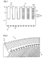
FIG 1 shows a part of the cooling-arrangement invented,
A number of laminate plates LP are stacked. Each laminate plate LP shows a number of slots SL. Because of the stacking the slots SL form a number of channels CH, which are used to support metal-windings MW of a stator-coil. - The stacked laminate plates LP are part of stator-segment. The stacked laminate plates LP show a first side S1, which is aligned to the rotor of the generator. The slots SL are located on this first side S1.
- At least one cooling-pipe CP is partly integrated into the stacked laminate plates LP. The partly integrated cooling-pipes CP penetrate the laminate plates LP on a second side S2 of the stacked laminate plates LP. The second side S2 is opposite to the first side S1.
- A heat transfer compound (not shown here) is arranged between the cooling-pipe CP and the stacked laminate plates LP. Thus the thermal conductivity of the thermal interface between irregular surfaces of the stacked laminate plates and the cooling-pipes is enhanced. Air gaps between the components are reduced or even eliminated, thus the cooling is improved. The compound may be ceramic, metal, carbon or a liquid.
-
FIG 2 shows a laminate plate LP according to the invention in a side-view. - A first side S1 of the laminate plate LP is aligned or aimed to an air gap, while the air gap is between the stator and the rotor of the generator. The first side S1 contains a number of slots SL. The slots SL may be punched out from a sheet of metal. The laminate plate LP may be manufactured by the same way.
- With reference to
FIG 1 a number of stacked laminate plates LP will form channels CH due to the slots SL. This channels CH are used to support the metal windings MW of the stator-coil. - Each metal winding MW is formed by a conductor CON, which is surrounded by a conductor-isolation CONI. Each slot SL shows a slot isolation lining SIL to insulate the bundle of metal windings MW.
- On top of each slot SL there is a recess RC. The recess RC is built to support a wedge WDG. When the metal windings MW of the electrical coils are inserted they are kept in place by help of the wedge WDG.
- A number of cooling-pipes CP is partly integrated into the (stacked) laminate plates LP and on the second side S2, which is opposite to the first side S1.
- Preferably the cross-section of the cooling-pipes CP is integrated by more than 50% into the (stacked) laminate-plates LP.
- This
FIG 2 shows only a part of the stator segment, which comprises the stacked laminate plates. The stacked laminate plates are shaped circular. -
FIG 3 shows in reference toFIG 1 andFIG 2 a 3D-view of a part of the arrangement invented. -
FIG 4 illustrates schematically a first preferred configuration according to the invention. - The generator (not shown here) contains a common cooling means like a heat exchanger HX for example.
- The common heat exchanger HX is connected to four segments seg1, seg2, seg3 and seg4 of the segmented stator of the generator.
- Each of the segments seg1 to seg4 shows a "cool" input and a "hot" output of the dedicated cooling-pipe, which are connected appropriate as shown here. Thus long connection-lines between the stator-segments seg1 to seg4 and the heat exchanger HX are avoided.
- The cooling-medium is divided and brought into four cooling-paths, each cooling path is dedicated to one of the segments seg1 to seg4.
- The divided cooling medium is combined after it leaved the dedicated cooling-path.
- Seen from the heat exchanger HX the cooling-pipes are regarded to be parallel coupled.
-
FIG 5 illustrates schematically a second preferred configuration according to the invention. - The generator (not shown here) contains a number of four cooling means like heat exchangers HXX for example.
- Each heat exchanger HXX is connected to a dedicated segment seg1, seg2, seg3 and seg4 of the segmented stator of the generator.
- Thus a number of four independent cooling-circuits are built, while each circuit contains a cooling-pipe of one of the segments seg1 to seg4.
- Preferably the cooling system according to
FIG 1 and according toFIG 5 may be combined. - As an example if the stator is partitioned into 8 segments, the cooling-system may comprise two cooling means. Each of the cooling means may supply and receive cooling medium from the cooling pipes of 4 stator segments.
-
FIG 6 and FIG 7 show stacked laminate plates LP, which are fixed by help of the cooling-pipe CP, to be used in the arrangement invented, -
FIG 8A illustrates schematically cooling-pipes CP, which are arranged in slots SL of the laminate plates LP according to the invention. -
FIG 8B illustrates schematically cooling-pipes CP, which are mounted on a surface of the laminate plates LP. This configuration is known before. - According to
FIG 8A the cooling-pipes CP are integrated part of the laminate plates LP. The cooling-pipe CP contains an inner perimeter with a length L1. - The length L2 represents the distance between two adjacent cooling pipes CP. As shown here the perimeter length L1 is substantial equal to the length L2.
- According to
FIG 8B the cooling pipes CP are no integrated part of the laminate plates LP, they are located on heat transferring plates HT substantially on the inner surface of the stator. The maximum width of the plates HT is equal to the distance of L2. - The illustration in
FIG 8A show an improved cooling efficiency compared to the illustration inFIG 8B .
Claims (16)
- Arrangement for cooling of an electrical generator, to be used within a wind-turbine,- where the generator comprises a stator, which contains at least two stator segments, and a rotor,- where at least one of the stator segments contains a number of stacked laminate plates (LP),- where the stacked laminate plates (LP) contain a number of slots (SL) at a first side (S1), while the first side (S1) of the stacked laminate plates is aligned to the rotor,- where the slots (SL) support a metal-winding (MW) of an stator coil,characterized in,- that at least one hollow cooling-pipe (CP) is partly integrated into the stacked laminate plates (LP) of the stator segment to cool its laminate plates (LP) by a cooling-medium, which is located into the cooling-pipes.
- Arrangement according to claim 1, characterized in that the partly integrated cooling pipe (CP) is designed in a way that an exchange of the stator segment together with the cooling pipe (CP) is allowed.
- Arrangement according to claim 1 or 2, characterized in that the partly integrated cooling-pipe (CP) is located on a second side (S2) of the stacked laminate plates (LP), while the second side (S2) is opposite to the first side (S1) .
- Arrangement according to one of the claims 1 to 3, characterized in- that the cooling pipe (CP) contain an input-connection and an output-connection for the cooling-medium,- while the cooling-medium enters the cooling-pipe (CP) via the input-connection with a first temperature and while the cooling-medium leaves the cooling-pipe (CP) via the output-connection with a second temperature, which is warmer than the first temperature.
- Arrangement according to claim 4, characterized in that each of stator segment contains at least one cooling-pipe (CP), which is dedicated to the stator segment.
- Arrangement according to one of the claims 1 to 5, characterized in that the generator contains a common heat exchanger, which is connected with each cooling pipe used in the stator-segments by the respective input-connections and output-connections.
- Arrangement according to one of the claims 1 to 5, characterized in that the generator contains a number of heat exchangers, while each heat exchanger is connected with the cooling pipe of a dedicated stator-segment by the respective input-connection and output-connection of the cooling pipe.
- Arrangement according to one of the claims 1 to 7, characterized in that a heat transfer compound is arranged between the cooling pipe (CP) and the stacked laminate plates (LP).
- Arrangement according to one of the claims 1 to 8, characterized in that the cooling-pipe contain a number of hairpin bends, which are shaped and arranged in the stator segment that voltages induced in the cooling-pipe (CP) are reduced.
- Arrangement according to one of the claims 1 to 7, characterized in that the cooling-pipe is part of a support-structure, which is constructed to support the laminate plates of the stator segment.
- Arrangement according to claim 10, characterized in that the cooling-pipe contains threads, which are constructed to tighten at least the stacked laminate plates.
- Arrangement according to claim 11, characterized in that the cooling-pipe contains one or more supporting flanges, which are preferably welded to the cooling-pipe.
- Arrangement according to claim 1, characterized in- that the generator contains an outer-rotor and an inner-stator, or- that the generator is used a direct drive generator of a wind-turbine.
- Arrangement according to claim 1, characterized in that the cooling medium is liquid.
- Arrangement according to claim 14, characterized in that the cooling medium is liquid and/or that the liquid cooling medium comprises an anti-freeze agent or oil.
- Arrangement according to one of the preceding claims, characterized in that the cooling-pipe (CP) is made of a non-magnetic material, preferably made of stainless-steel.
Priority Applications (6)
| Application Number | Priority Date | Filing Date | Title |
|---|---|---|---|
| EP09013958A EP2320080A1 (en) | 2009-11-06 | 2009-11-06 | Arrangement for cooling of an electrical generator |
| US12/904,338 US9698653B2 (en) | 2009-11-06 | 2010-10-14 | Electrical generator with dedicated cooling of stator segments |
| NZ588950A NZ588950A (en) | 2009-11-06 | 2010-11-01 | Cooling of an electrical generator using hollow cooling pipes integrated into stacked laminate plates of a stator |
| CA2720052A CA2720052A1 (en) | 2009-11-06 | 2010-11-04 | Arrangement for cooling of an electrical generator |
| JP2010248891A JP2011099442A (en) | 2009-11-06 | 2010-11-05 | Device for cooling generator |
| CN2010105413055A CN102055256A (en) | 2009-11-06 | 2010-11-05 | Arrangement for cooling of an electrical generator |
Applications Claiming Priority (1)
| Application Number | Priority Date | Filing Date | Title |
|---|---|---|---|
| EP09013958A EP2320080A1 (en) | 2009-11-06 | 2009-11-06 | Arrangement for cooling of an electrical generator |
Publications (1)
| Publication Number | Publication Date |
|---|---|
| EP2320080A1 true EP2320080A1 (en) | 2011-05-11 |
Family
ID=42115866
Family Applications (1)
| Application Number | Title | Priority Date | Filing Date |
|---|---|---|---|
| EP09013958A Withdrawn EP2320080A1 (en) | 2009-11-06 | 2009-11-06 | Arrangement for cooling of an electrical generator |
Country Status (6)
| Country | Link |
|---|---|
| US (1) | US9698653B2 (en) |
| EP (1) | EP2320080A1 (en) |
| JP (1) | JP2011099442A (en) |
| CN (1) | CN102055256A (en) |
| CA (1) | CA2720052A1 (en) |
| NZ (1) | NZ588950A (en) |
Cited By (12)
| Publication number | Priority date | Publication date | Assignee | Title |
|---|---|---|---|---|
| EP2395629A1 (en) | 2010-06-11 | 2011-12-14 | Siemens Aktiengesellschaft | Stator element |
| WO2012040535A3 (en) * | 2010-09-23 | 2012-05-10 | Northern Power Systems Utility Scale, Inc. | Electromagnetic rotary machines having modular active-coil portions and modules for such machines |
| ITMI20121301A1 (en) * | 2012-07-25 | 2014-01-26 | Wilic Sarl | ACTIVE SEGMENT OF A ROTARY ELECTRIC MACHINE FOR THE AIRCONDITIONER, ROTARY ELECTRIC MACHINE, AND VENTILATOR |
| ITMI20121304A1 (en) * | 2012-07-25 | 2014-01-26 | Wilic Sarl | ROTOR OF A ROTATING ELECTRIC MACHINE FOR GAS MILLER AND AIRCONDITIONER INCLUDING SUCH ROTOR |
| US8789274B2 (en) | 2010-09-23 | 2014-07-29 | Northern Power Systems, Inc. | Method and system for servicing a horizontal-axis wind power unit |
| US8912704B2 (en) | 2010-09-23 | 2014-12-16 | Northern Power Systems, Inc. | Sectionalized electromechanical machines having low torque ripple and low cogging torque characteristics |
| WO2015040586A2 (en) | 2013-09-19 | 2015-03-26 | Wilic S.Ar.L. | Wind turbine rotating electric machine stator |
| US9281731B2 (en) | 2010-09-23 | 2016-03-08 | Northem Power Systems, Inc. | Method for maintaining a machine having a rotor and a stator |
| US9359994B2 (en) | 2010-09-23 | 2016-06-07 | Northern Power Systems, Inc. | Module-handling tool for installing/removing modules into/from an electromagnetic rotary machine having a modularized active portion |
| EP2525473A3 (en) * | 2011-05-17 | 2017-04-26 | Lloyd Dynamowerke GmbH | Stator and generator with a stator |
| AT523102A1 (en) * | 2019-10-31 | 2021-05-15 | B & R Ind Automation Gmbh | Transport device in the form of a long stator linear motor |
| AT523101A1 (en) * | 2019-10-31 | 2021-05-15 | B & R Ind Automation Gmbh | Transport device in the form of a long stator linear motor |
Families Citing this family (42)
| Publication number | Priority date | Publication date | Assignee | Title |
|---|---|---|---|---|
| US8513840B2 (en) | 2010-05-04 | 2013-08-20 | Remy Technologies, Llc | Electric machine cooling system and method |
| WO2011153533A2 (en) | 2010-06-04 | 2011-12-08 | Remy Technologies, Llc | Electric machine cooling system and method |
| EP2580846B1 (en) | 2010-06-08 | 2018-07-18 | Remy Technologies, LLC | Electric machine cooling system and method |
| US8456046B2 (en) | 2010-06-08 | 2013-06-04 | Remy Technologies, Llc | Gravity fed oil cooling for an electric machine |
| US8519581B2 (en) | 2010-06-08 | 2013-08-27 | Remy Technologies, Llc | Electric machine cooling system and method |
| US8482169B2 (en) | 2010-06-14 | 2013-07-09 | Remy Technologies, Llc | Electric machine cooling system and method |
| US8614538B2 (en) | 2010-06-14 | 2013-12-24 | Remy Technologies, Llc | Electric machine cooling system and method |
| US8446056B2 (en) | 2010-09-29 | 2013-05-21 | Remy Technologies, Llc | Electric machine cooling system and method |
| US8593021B2 (en) | 2010-10-04 | 2013-11-26 | Remy Technologies, Llc | Coolant drainage system and method for electric machines |
| US8492952B2 (en) | 2010-10-04 | 2013-07-23 | Remy Technologies, Llc | Coolant channels for electric machine stator |
| US8508085B2 (en) | 2010-10-04 | 2013-08-13 | Remy Technologies, Llc | Internal cooling of stator assembly in an electric machine |
| US8395287B2 (en) | 2010-10-04 | 2013-03-12 | Remy Technologies, Llc | Coolant channels for electric machine stator |
| EP2451048A1 (en) * | 2010-11-04 | 2012-05-09 | Siemens Aktiengesellschaft | Magnetic cap element for closing a cooling channel in a stator of a generator |
| US8648506B2 (en) | 2010-11-09 | 2014-02-11 | Remy Technologies, Llc | Rotor lamination cooling system and method |
| US8497608B2 (en) | 2011-01-28 | 2013-07-30 | Remy Technologies, Llc | Electric machine cooling system and method |
| WO2012145302A2 (en) | 2011-04-18 | 2012-10-26 | Remy Technologies, Llc | Electric machine module cooling system and method |
| US8692425B2 (en) | 2011-05-10 | 2014-04-08 | Remy Technologies, Llc | Cooling combinations for electric machines |
| WO2012167274A1 (en) | 2011-06-03 | 2012-12-06 | Remy Technologies, Llc | Electric machine module cooling system and method |
| US20120318479A1 (en) * | 2011-06-14 | 2012-12-20 | Fukuta Electric & Machinery Co., Ltd. | Liquid cooled motor assembly and cover thereof |
| US9041260B2 (en) | 2011-07-08 | 2015-05-26 | Remy Technologies, Llc | Cooling system and method for an electronic machine |
| US8803381B2 (en) | 2011-07-11 | 2014-08-12 | Remy Technologies, Llc | Electric machine with cooling pipe coiled around stator assembly |
| US8546982B2 (en) | 2011-07-12 | 2013-10-01 | Remy Technologies, Llc | Electric machine module cooling system and method |
| US9048710B2 (en) | 2011-08-29 | 2015-06-02 | Remy Technologies, Llc | Electric machine module cooling system and method |
| JP5740254B2 (en) * | 2011-09-02 | 2015-06-24 | 株式会社東芝 | Water-cooled wind power generator and generator cooling method for wind power generator |
| DE102011082353B4 (en) * | 2011-09-08 | 2021-04-01 | Siemens Aktiengesellschaft | Stator for an electric motor |
| US8975792B2 (en) | 2011-09-13 | 2015-03-10 | Remy Technologies, Llc | Electric machine module cooling system and method |
| US9099900B2 (en) | 2011-12-06 | 2015-08-04 | Remy Technologies, Llc | Electric machine module cooling system and method |
| US9331543B2 (en) | 2012-04-05 | 2016-05-03 | Remy Technologies, Llc | Electric machine module cooling system and method |
| DK201270179A (en) * | 2012-04-11 | 2013-10-11 | Envision Energy Denmark Aps | Wind turbine with improved cooling |
| US10069375B2 (en) | 2012-05-02 | 2018-09-04 | Borgwarner Inc. | Electric machine module cooling system and method |
| US20140262155A1 (en) * | 2013-03-14 | 2014-09-18 | Lincoln Global, Inc. | Orbital welding system with cooled drive housing |
| WO2015037069A1 (en) * | 2013-09-11 | 2015-03-19 | 株式会社日立製作所 | Dynamo-electric machine |
| DE102015210662A1 (en) * | 2015-06-11 | 2016-12-15 | Wobben Properties Gmbh | Statorring for an electric generator, generator and wind turbine with selbigem |
| US10804755B2 (en) * | 2017-07-25 | 2020-10-13 | Toshiba International Corporation | Stator core with at least three cooling pipes with end crimps |
| CN107332373A (en) * | 2017-08-22 | 2017-11-07 | 彭希南 | Permanent magnetic brushless stator and rotor structure of a kind of high pulling torque with cooling water pipe |
| US10756598B2 (en) | 2017-10-02 | 2020-08-25 | Ge Aviation Systems Llc | Method and apparatus for cooling a rotor assembly |
| FI128225B (en) | 2018-03-20 | 2020-01-15 | Lappeenrannan Teknillinen Yliopisto | A stator of an electric machine and an electric machine |
| CN111697766A (en) * | 2019-03-14 | 2020-09-22 | 南京德朔实业有限公司 | Electric tool and motor thereof |
| CN111817457A (en) * | 2020-07-03 | 2020-10-23 | 浙江实日机电科技有限公司 | Stator core of automobile starting motor and processing technology thereof |
| US20220003128A1 (en) * | 2020-07-06 | 2022-01-06 | General Electric Company | Dual rotor electric machine |
| US11719122B2 (en) | 2021-02-08 | 2023-08-08 | General Electric Company | Gas turbine engines including embedded electrical machines and associated cooling systems |
| CN113370195B (en) * | 2021-06-30 | 2022-09-09 | 哈尔滨科能熔敷科技股份有限公司 | Mechanical arm applied to high-temperature working condition |
Citations (10)
| Publication number | Priority date | Publication date | Assignee | Title |
|---|---|---|---|---|
| US5473207A (en) * | 1993-11-04 | 1995-12-05 | General Electric Co. | Cooling pads for water-cooled stator cores in dynamoelectric machines and methods of fabrication |
| DE19604643A1 (en) * | 1996-02-08 | 1997-08-14 | Krauss Maffei Ag | Linear motor with integrated cooling e.g. for production machines |
| WO1999017422A1 (en) * | 1997-09-30 | 1999-04-08 | Abb Ab | Method for mounting a cooling tube in a cooling tube channel |
| WO2001006623A1 (en) * | 1999-04-23 | 2001-01-25 | Aerpac Holding B.V. | Generator |
| DE10103447A1 (en) * | 2001-01-25 | 2002-08-01 | Baumueller Nuernberg Gmbh | Corrugated tube stator cooling in an electrical machine |
| WO2002078150A2 (en) * | 2001-03-27 | 2002-10-03 | Rexroth Indramat Gmbh | Cooled primary or secondary part of an electric motor |
| US20040012272A1 (en) * | 2002-07-18 | 2004-01-22 | Martin Houle | Liquid cooling arrangement for electric machines |
| US20050082836A1 (en) * | 1999-09-24 | 2005-04-21 | Lagerwey Hendrik L. | Wind power generator |
| EP2182612A1 (en) | 2008-10-28 | 2010-05-05 | Siemens Aktiengesellschaft | Arrangement for cooling of an electrical machine |
| EP2320540A1 (en) | 2009-11-05 | 2011-05-11 | Siemens Aktiengesellschaft | Arrangement for cooling of an electrical machine |
Family Cites Families (18)
| Publication number | Priority date | Publication date | Assignee | Title |
|---|---|---|---|---|
| US3681628A (en) | 1970-09-14 | 1972-08-01 | Christoslaw Krastchew | Cooling arrangement for a dynamoelectric machine |
| US3704078A (en) * | 1971-01-22 | 1972-11-28 | Hydr O Matic Pump Co | Deep well type pump |
| JPS5949781B2 (en) * | 1976-10-21 | 1984-12-05 | 株式会社東芝 | rotating electric machine |
| US5408152A (en) * | 1994-03-28 | 1995-04-18 | Westinghouse Electric Corporation | Method of improving heat transfer in stator coil cooling tubes |
| AU3052897A (en) * | 1996-05-29 | 1998-01-05 | Asea Brown Boveri Ab | Axial cooling tubes provided with clamping means |
| JPH11307430A (en) * | 1998-04-23 | 1999-11-05 | Canon Inc | Aligner, manufacture of device, and drive |
| JP2001119872A (en) * | 1999-10-15 | 2001-04-27 | Mitsubishi Electric Corp | Synchronous rotating electric machine, wind turbine power generator, and manufacturing methods for them |
| JP4111418B2 (en) | 2001-02-28 | 2008-07-02 | ペンタックス株式会社 | Calcium phosphate cement for living bone reinforcement treatment capable of forming a high-strength hardened body |
| US6330809B1 (en) * | 2000-12-08 | 2001-12-18 | General Electric Company | Application of a chiller in an apparatus for cooling a generator/motor |
| ES2319392T3 (en) | 2001-04-20 | 2009-05-07 | Converteam Ltd | REFRIGERATION OF A WINDING ENTREHIERRO OF ELECTRICAL MACHINES. |
| US20040100154A1 (en) * | 2002-11-26 | 2004-05-27 | Rahman Khwaja M. | Concentrated winding electric motor having optimized winding cooling and slot fill |
| US7193342B2 (en) * | 2002-12-17 | 2007-03-20 | Caterpillar Inc | Apparatus for cooling of electrical devices |
| DE102004052070A1 (en) | 2004-10-26 | 2006-05-18 | Siemens Ag | Electric machine |
| US7443066B2 (en) * | 2005-07-29 | 2008-10-28 | General Electric Company | Methods and apparatus for cooling wind turbine generators |
| US7545060B2 (en) * | 2006-03-14 | 2009-06-09 | Gm Global Technology Operations, Inc. | Method and apparatus for heat removal from electric motor winding end-turns |
| US7592721B2 (en) | 2006-09-20 | 2009-09-22 | American Superconductor Corporation | Torque transmission assembly for superconducting rotating machines |
| DK2109208T3 (en) | 2008-04-10 | 2013-11-11 | Siemens Ag | Stator device, generator and wind turbine |
| FI120782B (en) | 2008-04-18 | 2010-02-26 | Abb Oy | Heat sink for electric machine |
-
2009
- 2009-11-06 EP EP09013958A patent/EP2320080A1/en not_active Withdrawn
-
2010
- 2010-10-14 US US12/904,338 patent/US9698653B2/en not_active Expired - Fee Related
- 2010-11-01 NZ NZ588950A patent/NZ588950A/en not_active IP Right Cessation
- 2010-11-04 CA CA2720052A patent/CA2720052A1/en not_active Abandoned
- 2010-11-05 JP JP2010248891A patent/JP2011099442A/en active Pending
- 2010-11-05 CN CN2010105413055A patent/CN102055256A/en active Pending
Patent Citations (11)
| Publication number | Priority date | Publication date | Assignee | Title |
|---|---|---|---|---|
| US5473207A (en) * | 1993-11-04 | 1995-12-05 | General Electric Co. | Cooling pads for water-cooled stator cores in dynamoelectric machines and methods of fabrication |
| DE19604643A1 (en) * | 1996-02-08 | 1997-08-14 | Krauss Maffei Ag | Linear motor with integrated cooling e.g. for production machines |
| WO1999017422A1 (en) * | 1997-09-30 | 1999-04-08 | Abb Ab | Method for mounting a cooling tube in a cooling tube channel |
| WO2001006623A1 (en) * | 1999-04-23 | 2001-01-25 | Aerpac Holding B.V. | Generator |
| US20050082836A1 (en) * | 1999-09-24 | 2005-04-21 | Lagerwey Hendrik L. | Wind power generator |
| DE10103447A1 (en) * | 2001-01-25 | 2002-08-01 | Baumueller Nuernberg Gmbh | Corrugated tube stator cooling in an electrical machine |
| WO2002078150A2 (en) * | 2001-03-27 | 2002-10-03 | Rexroth Indramat Gmbh | Cooled primary or secondary part of an electric motor |
| US20040012272A1 (en) * | 2002-07-18 | 2004-01-22 | Martin Houle | Liquid cooling arrangement for electric machines |
| US20050067904A1 (en) | 2002-07-18 | 2005-03-31 | Tm4 Inc. | Liquid cooling arrangement for electric machines |
| EP2182612A1 (en) | 2008-10-28 | 2010-05-05 | Siemens Aktiengesellschaft | Arrangement for cooling of an electrical machine |
| EP2320540A1 (en) | 2009-11-05 | 2011-05-11 | Siemens Aktiengesellschaft | Arrangement for cooling of an electrical machine |
Cited By (19)
| Publication number | Priority date | Publication date | Assignee | Title |
|---|---|---|---|---|
| US9276442B2 (en) | 2010-06-11 | 2016-03-01 | Siemens Aktiengesellschaft | Stator element with cooling element arranged on the backside of the yoke |
| EP2395629A1 (en) | 2010-06-11 | 2011-12-14 | Siemens Aktiengesellschaft | Stator element |
| US9359994B2 (en) | 2010-09-23 | 2016-06-07 | Northern Power Systems, Inc. | Module-handling tool for installing/removing modules into/from an electromagnetic rotary machine having a modularized active portion |
| US9281731B2 (en) | 2010-09-23 | 2016-03-08 | Northem Power Systems, Inc. | Method for maintaining a machine having a rotor and a stator |
| US9812909B2 (en) | 2010-09-23 | 2017-11-07 | Weg Electric Corp | Sectionalized electromechanical machines having low torque ripple and low cogging torque characteristics |
| WO2012040535A3 (en) * | 2010-09-23 | 2012-05-10 | Northern Power Systems Utility Scale, Inc. | Electromagnetic rotary machines having modular active-coil portions and modules for such machines |
| US8789274B2 (en) | 2010-09-23 | 2014-07-29 | Northern Power Systems, Inc. | Method and system for servicing a horizontal-axis wind power unit |
| US8816546B2 (en) | 2010-09-23 | 2014-08-26 | Northern Power Systems, Inc. | Electromagnetic rotary machines having modular active-coil portions and modules for such machines |
| US8912704B2 (en) | 2010-09-23 | 2014-12-16 | Northern Power Systems, Inc. | Sectionalized electromechanical machines having low torque ripple and low cogging torque characteristics |
| EP2525473A3 (en) * | 2011-05-17 | 2017-04-26 | Lloyd Dynamowerke GmbH | Stator and generator with a stator |
| ITMI20121301A1 (en) * | 2012-07-25 | 2014-01-26 | Wilic Sarl | ACTIVE SEGMENT OF A ROTARY ELECTRIC MACHINE FOR THE AIRCONDITIONER, ROTARY ELECTRIC MACHINE, AND VENTILATOR |
| ITMI20121304A1 (en) * | 2012-07-25 | 2014-01-26 | Wilic Sarl | ROTOR OF A ROTATING ELECTRIC MACHINE FOR GAS MILLER AND AIRCONDITIONER INCLUDING SUCH ROTOR |
| WO2014016802A3 (en) * | 2012-07-25 | 2014-03-20 | Wilic S.Ar.L. | Active segment of a wind turbine rotary electric machine, rotary electric machine, and wind turbine |
| US9698641B2 (en) | 2012-07-25 | 2017-07-04 | Windfin B.V. | Active segment of a wind turbine rotary electric machine, rotary electric machine, and wind turbine |
| WO2014016805A3 (en) * | 2012-07-25 | 2014-03-20 | Wilic S.Ar.L. | Wind turbine rotary electric machine rotor and wind turbine comprising such a rotor |
| US9929611B2 (en) | 2012-07-25 | 2018-03-27 | Windfin B.V. | Wind turbine rotary electric machine rotor, and wind turbine comprising such a rotor |
| WO2015040586A2 (en) | 2013-09-19 | 2015-03-26 | Wilic S.Ar.L. | Wind turbine rotating electric machine stator |
| AT523102A1 (en) * | 2019-10-31 | 2021-05-15 | B & R Ind Automation Gmbh | Transport device in the form of a long stator linear motor |
| AT523101A1 (en) * | 2019-10-31 | 2021-05-15 | B & R Ind Automation Gmbh | Transport device in the form of a long stator linear motor |
Also Published As
| Publication number | Publication date |
|---|---|
| US9698653B2 (en) | 2017-07-04 |
| JP2011099442A (en) | 2011-05-19 |
| NZ588950A (en) | 2012-05-25 |
| US20110109095A1 (en) | 2011-05-12 |
| CN102055256A (en) | 2011-05-11 |
| CA2720052A1 (en) | 2011-05-06 |
Similar Documents
| Publication | Publication Date | Title |
|---|---|---|
| US9698653B2 (en) | Electrical generator with dedicated cooling of stator segments | |
| EP2182612A1 (en) | Arrangement for cooling of an electrical machine | |
| EP2182570A1 (en) | Arrangement for cooling of an electrical machine | |
| EP2518868B1 (en) | Cooling arrangement for an electric machine | |
| US8242644B2 (en) | Arrangement for cooling of an electrical machine | |
| KR101365641B1 (en) | Arrangement and method for cooling an electrical machine | |
| EP2110931A2 (en) | Cooling element for an electrical machine | |
| EP2651009A2 (en) | Wind turbine with improved cooling | |
| EP2657520B1 (en) | Cooling and supporting a stator segment of an electro-mechanical machine, especially for wind turbine application | |
| US20100225183A1 (en) | Stator cooling structure for superconducting rotating machine | |
| EP2744074A2 (en) | Cooling and supporting a stator segment of an electro-mechanical machine, especially for wind turbine application | |
| EP2445087B1 (en) | A generator, in particular for a wind turbine | |
| EP2477311B1 (en) | Generator, in particular for a wind turbine | |
| CN113726042A (en) | Cooling device, generator and wind generating set | |
| KR101055009B1 (en) | Generator and electric motor | |
| EP2442060B1 (en) | A generator, in particular for a wind turbine | |
| KR101056400B1 (en) | Rotor core for rotary electric machine | |
| KR20090110794A (en) | Cooling element for an electrical machine |
Legal Events
| Date | Code | Title | Description |
|---|---|---|---|
| PUAI | Public reference made under article 153(3) epc to a published international application that has entered the european phase |
Free format text: ORIGINAL CODE: 0009012 |
|
| AK | Designated contracting states |
Kind code of ref document: A1 Designated state(s): AT BE BG CH CY CZ DE DK EE ES FI FR GB GR HR HU IE IS IT LI LT LU LV MC MK MT NL NO PL PT RO SE SI SK SM TR |
|
| AX | Request for extension of the european patent |
Extension state: AL BA RS |
|
| 17P | Request for examination filed |
Effective date: 20111010 |
|
| TPAC | Observations filed by third parties |
Free format text: ORIGINAL CODE: EPIDOSNTIPA |
|
| RAP1 | Party data changed (applicant data changed or rights of an application transferred) |
Owner name: SIEMENS AKTIENGESELLSCHAFT |
|
| RAP1 | Party data changed (applicant data changed or rights of an application transferred) |
Owner name: SIEMENS AKTIENGESELLSCHAFT |
|
| STAA | Information on the status of an ep patent application or granted ep patent |
Free format text: STATUS: THE APPLICATION IS DEEMED TO BE WITHDRAWN |
|
| 18D | Application deemed to be withdrawn |
Effective date: 20180502 |