EP2268194B1 - Imaging system for combined full-color reflectance and near-infrared imaging - Google Patents
Imaging system for combined full-color reflectance and near-infrared imaging Download PDFInfo
- Publication number
- EP2268194B1 EP2268194B1 EP09721252.6A EP09721252A EP2268194B1 EP 2268194 B1 EP2268194 B1 EP 2268194B1 EP 09721252 A EP09721252 A EP 09721252A EP 2268194 B1 EP2268194 B1 EP 2268194B1
- Authority
- EP
- European Patent Office
- Prior art keywords
- light
- nir
- red
- reflectance
- blue
- Prior art date
- Legal status (The legal status is an assumption and is not a legal conclusion. Google has not performed a legal analysis and makes no representation as to the accuracy of the status listed.)
- Active
Links
- 238000003384 imaging method Methods 0.000 title claims description 42
- 238000003333 near-infrared imaging Methods 0.000 title 1
- 238000005286 illumination Methods 0.000 claims description 60
- 230000003595 spectral effect Effects 0.000 claims description 39
- 238000000034 method Methods 0.000 claims description 11
- 230000005540 biological transmission Effects 0.000 claims description 9
- 230000000750 progressive effect Effects 0.000 claims description 5
- 238000004891 communication Methods 0.000 claims description 2
- 230000001131 transforming effect Effects 0.000 claims description 2
- 210000001519 tissue Anatomy 0.000 description 15
- 238000010586 diagram Methods 0.000 description 12
- 238000001429 visible spectrum Methods 0.000 description 9
- 241000023320 Luma <angiosperm> Species 0.000 description 8
- OSWPMRLSEDHDFF-UHFFFAOYSA-N methyl salicylate Chemical compound COC(=O)C1=CC=CC=C1O OSWPMRLSEDHDFF-UHFFFAOYSA-N 0.000 description 8
- 230000005284 excitation Effects 0.000 description 7
- 238000001228 spectrum Methods 0.000 description 5
- 230000002123 temporal effect Effects 0.000 description 5
- 239000002872 contrast media Substances 0.000 description 4
- 238000012545 processing Methods 0.000 description 4
- 239000003086 colorant Substances 0.000 description 3
- 238000012986 modification Methods 0.000 description 3
- 230000004048 modification Effects 0.000 description 3
- 230000003287 optical effect Effects 0.000 description 3
- 239000007787 solid Substances 0.000 description 3
- 230000001360 synchronised effect Effects 0.000 description 3
- 230000000903 blocking effect Effects 0.000 description 2
- 239000002131 composite material Substances 0.000 description 2
- 238000013461 design Methods 0.000 description 2
- 238000002059 diagnostic imaging Methods 0.000 description 2
- 230000000694 effects Effects 0.000 description 2
- 238000005516 engineering process Methods 0.000 description 2
- 238000002073 fluorescence micrograph Methods 0.000 description 2
- 229910052736 halogen Inorganic materials 0.000 description 2
- 150000002367 halogens Chemical class 0.000 description 2
- 239000000203 mixture Substances 0.000 description 2
- 230000008447 perception Effects 0.000 description 2
- 230000008569 process Effects 0.000 description 2
- 239000004065 semiconductor Substances 0.000 description 2
- 238000012800 visualization Methods 0.000 description 2
- 238000002835 absorbance Methods 0.000 description 1
- 238000013459 approach Methods 0.000 description 1
- 238000003491 array Methods 0.000 description 1
- 230000004888 barrier function Effects 0.000 description 1
- 210000000941 bile Anatomy 0.000 description 1
- 230000004397 blinking Effects 0.000 description 1
- 239000008280 blood Substances 0.000 description 1
- 210000004369 blood Anatomy 0.000 description 1
- 238000012937 correction Methods 0.000 description 1
- 238000001514 detection method Methods 0.000 description 1
- 201000010099 disease Diseases 0.000 description 1
- 208000037265 diseases, disorders, signs and symptoms Diseases 0.000 description 1
- 238000001839 endoscopy Methods 0.000 description 1
- 239000000835 fiber Substances 0.000 description 1
- 238000000799 fluorescence microscopy Methods 0.000 description 1
- 230000006870 function Effects 0.000 description 1
- MOFVSTNWEDAEEK-UHFFFAOYSA-M indocyanine green Chemical compound [Na+].[O-]S(=O)(=O)CCCCN1C2=CC=C3C=CC=CC3=C2C(C)(C)C1=CC=CC=CC=CC1=[N+](CCCCS([O-])(=O)=O)C2=CC=C(C=CC=C3)C3=C2C1(C)C MOFVSTNWEDAEEK-UHFFFAOYSA-M 0.000 description 1
- 229960004657 indocyanine green Drugs 0.000 description 1
- 230000002452 interceptive effect Effects 0.000 description 1
- 210000002751 lymph Anatomy 0.000 description 1
- 238000009877 rendering Methods 0.000 description 1
- 230000035945 sensitivity Effects 0.000 description 1
- 238000000926 separation method Methods 0.000 description 1
- 230000008685 targeting Effects 0.000 description 1
- 238000012546 transfer Methods 0.000 description 1
- 230000000007 visual effect Effects 0.000 description 1
Images


Classifications
-
- A—HUMAN NECESSITIES
- A61—MEDICAL OR VETERINARY SCIENCE; HYGIENE
- A61B—DIAGNOSIS; SURGERY; IDENTIFICATION
- A61B5/00—Measuring for diagnostic purposes; Identification of persons
- A61B5/0059—Measuring for diagnostic purposes; Identification of persons using light, e.g. diagnosis by transillumination, diascopy, fluorescence
- A61B5/0082—Measuring for diagnostic purposes; Identification of persons using light, e.g. diagnosis by transillumination, diascopy, fluorescence adapted for particular medical purposes
- A61B5/0084—Measuring for diagnostic purposes; Identification of persons using light, e.g. diagnosis by transillumination, diascopy, fluorescence adapted for particular medical purposes for introduction into the body, e.g. by catheters
- A61B5/0086—Measuring for diagnostic purposes; Identification of persons using light, e.g. diagnosis by transillumination, diascopy, fluorescence adapted for particular medical purposes for introduction into the body, e.g. by catheters using infrared radiation
-
- A—HUMAN NECESSITIES
- A61—MEDICAL OR VETERINARY SCIENCE; HYGIENE
- A61B—DIAGNOSIS; SURGERY; IDENTIFICATION
- A61B1/00—Instruments for performing medical examinations of the interior of cavities or tubes of the body by visual or photographical inspection, e.g. endoscopes; Illuminating arrangements therefor
- A61B1/00002—Operational features of endoscopes
- A61B1/00043—Operational features of endoscopes provided with output arrangements
- A61B1/00045—Display arrangement
- A61B1/0005—Display arrangement combining images e.g. side-by-side, superimposed or tiled
-
- A—HUMAN NECESSITIES
- A61—MEDICAL OR VETERINARY SCIENCE; HYGIENE
- A61B—DIAGNOSIS; SURGERY; IDENTIFICATION
- A61B1/00—Instruments for performing medical examinations of the interior of cavities or tubes of the body by visual or photographical inspection, e.g. endoscopes; Illuminating arrangements therefor
- A61B1/00163—Optical arrangements
- A61B1/00186—Optical arrangements with imaging filters
-
- A—HUMAN NECESSITIES
- A61—MEDICAL OR VETERINARY SCIENCE; HYGIENE
- A61B—DIAGNOSIS; SURGERY; IDENTIFICATION
- A61B1/00—Instruments for performing medical examinations of the interior of cavities or tubes of the body by visual or photographical inspection, e.g. endoscopes; Illuminating arrangements therefor
- A61B1/04—Instruments for performing medical examinations of the interior of cavities or tubes of the body by visual or photographical inspection, e.g. endoscopes; Illuminating arrangements therefor combined with photographic or television appliances
- A61B1/042—Instruments for performing medical examinations of the interior of cavities or tubes of the body by visual or photographical inspection, e.g. endoscopes; Illuminating arrangements therefor combined with photographic or television appliances characterised by a proximal camera, e.g. a CCD camera
-
- A—HUMAN NECESSITIES
- A61—MEDICAL OR VETERINARY SCIENCE; HYGIENE
- A61B—DIAGNOSIS; SURGERY; IDENTIFICATION
- A61B1/00—Instruments for performing medical examinations of the interior of cavities or tubes of the body by visual or photographical inspection, e.g. endoscopes; Illuminating arrangements therefor
- A61B1/04—Instruments for performing medical examinations of the interior of cavities or tubes of the body by visual or photographical inspection, e.g. endoscopes; Illuminating arrangements therefor combined with photographic or television appliances
- A61B1/043—Instruments for performing medical examinations of the interior of cavities or tubes of the body by visual or photographical inspection, e.g. endoscopes; Illuminating arrangements therefor combined with photographic or television appliances for fluorescence imaging
-
- A—HUMAN NECESSITIES
- A61—MEDICAL OR VETERINARY SCIENCE; HYGIENE
- A61B—DIAGNOSIS; SURGERY; IDENTIFICATION
- A61B1/00—Instruments for performing medical examinations of the interior of cavities or tubes of the body by visual or photographical inspection, e.g. endoscopes; Illuminating arrangements therefor
- A61B1/04—Instruments for performing medical examinations of the interior of cavities or tubes of the body by visual or photographical inspection, e.g. endoscopes; Illuminating arrangements therefor combined with photographic or television appliances
- A61B1/045—Control thereof
-
- A—HUMAN NECESSITIES
- A61—MEDICAL OR VETERINARY SCIENCE; HYGIENE
- A61B—DIAGNOSIS; SURGERY; IDENTIFICATION
- A61B1/00—Instruments for performing medical examinations of the interior of cavities or tubes of the body by visual or photographical inspection, e.g. endoscopes; Illuminating arrangements therefor
- A61B1/04—Instruments for performing medical examinations of the interior of cavities or tubes of the body by visual or photographical inspection, e.g. endoscopes; Illuminating arrangements therefor combined with photographic or television appliances
- A61B1/046—Instruments for performing medical examinations of the interior of cavities or tubes of the body by visual or photographical inspection, e.g. endoscopes; Illuminating arrangements therefor combined with photographic or television appliances for infrared imaging
-
- A—HUMAN NECESSITIES
- A61—MEDICAL OR VETERINARY SCIENCE; HYGIENE
- A61B—DIAGNOSIS; SURGERY; IDENTIFICATION
- A61B1/00—Instruments for performing medical examinations of the interior of cavities or tubes of the body by visual or photographical inspection, e.g. endoscopes; Illuminating arrangements therefor
- A61B1/06—Instruments for performing medical examinations of the interior of cavities or tubes of the body by visual or photographical inspection, e.g. endoscopes; Illuminating arrangements therefor with illuminating arrangements
- A61B1/0638—Instruments for performing medical examinations of the interior of cavities or tubes of the body by visual or photographical inspection, e.g. endoscopes; Illuminating arrangements therefor with illuminating arrangements providing two or more wavelengths
-
- A—HUMAN NECESSITIES
- A61—MEDICAL OR VETERINARY SCIENCE; HYGIENE
- A61B—DIAGNOSIS; SURGERY; IDENTIFICATION
- A61B1/00—Instruments for performing medical examinations of the interior of cavities or tubes of the body by visual or photographical inspection, e.g. endoscopes; Illuminating arrangements therefor
- A61B1/06—Instruments for performing medical examinations of the interior of cavities or tubes of the body by visual or photographical inspection, e.g. endoscopes; Illuminating arrangements therefor with illuminating arrangements
- A61B1/0646—Instruments for performing medical examinations of the interior of cavities or tubes of the body by visual or photographical inspection, e.g. endoscopes; Illuminating arrangements therefor with illuminating arrangements with illumination filters
-
- A—HUMAN NECESSITIES
- A61—MEDICAL OR VETERINARY SCIENCE; HYGIENE
- A61B—DIAGNOSIS; SURGERY; IDENTIFICATION
- A61B1/00—Instruments for performing medical examinations of the interior of cavities or tubes of the body by visual or photographical inspection, e.g. endoscopes; Illuminating arrangements therefor
- A61B1/06—Instruments for performing medical examinations of the interior of cavities or tubes of the body by visual or photographical inspection, e.g. endoscopes; Illuminating arrangements therefor with illuminating arrangements
- A61B1/0655—Control therefor
-
- A—HUMAN NECESSITIES
- A61—MEDICAL OR VETERINARY SCIENCE; HYGIENE
- A61B—DIAGNOSIS; SURGERY; IDENTIFICATION
- A61B5/00—Measuring for diagnostic purposes; Identification of persons
- A61B5/0059—Measuring for diagnostic purposes; Identification of persons using light, e.g. diagnosis by transillumination, diascopy, fluorescence
- A61B5/0062—Arrangements for scanning
-
- A—HUMAN NECESSITIES
- A61—MEDICAL OR VETERINARY SCIENCE; HYGIENE
- A61B—DIAGNOSIS; SURGERY; IDENTIFICATION
- A61B5/00—Measuring for diagnostic purposes; Identification of persons
- A61B5/0059—Measuring for diagnostic purposes; Identification of persons using light, e.g. diagnosis by transillumination, diascopy, fluorescence
- A61B5/0071—Measuring for diagnostic purposes; Identification of persons using light, e.g. diagnosis by transillumination, diascopy, fluorescence by measuring fluorescence emission
-
- A—HUMAN NECESSITIES
- A61—MEDICAL OR VETERINARY SCIENCE; HYGIENE
- A61B—DIAGNOSIS; SURGERY; IDENTIFICATION
- A61B5/00—Measuring for diagnostic purposes; Identification of persons
- A61B5/41—Detecting, measuring or recording for evaluating the immune or lymphatic systems
- A61B5/414—Evaluating particular organs or parts of the immune or lymphatic systems
- A61B5/418—Evaluating particular organs or parts of the immune or lymphatic systems lymph vessels, ducts or nodes
-
- A—HUMAN NECESSITIES
- A61—MEDICAL OR VETERINARY SCIENCE; HYGIENE
- A61B—DIAGNOSIS; SURGERY; IDENTIFICATION
- A61B5/00—Measuring for diagnostic purposes; Identification of persons
- A61B5/74—Details of notification to user or communication with user or patient ; user input means
- A61B5/742—Details of notification to user or communication with user or patient ; user input means using visual displays
- A61B5/7425—Displaying combinations of multiple images regardless of image source, e.g. displaying a reference anatomical image with a live image
-
- G—PHYSICS
- G02—OPTICS
- G02B—OPTICAL ELEMENTS, SYSTEMS OR APPARATUS
- G02B27/00—Optical systems or apparatus not provided for by any of the groups G02B1/00 - G02B26/00, G02B30/00
- G02B27/10—Beam splitting or combining systems
- G02B27/1006—Beam splitting or combining systems for splitting or combining different wavelengths
- G02B27/1013—Beam splitting or combining systems for splitting or combining different wavelengths for colour or multispectral image sensors, e.g. splitting an image into monochromatic image components on respective sensors
-
- A—HUMAN NECESSITIES
- A61—MEDICAL OR VETERINARY SCIENCE; HYGIENE
- A61B—DIAGNOSIS; SURGERY; IDENTIFICATION
- A61B1/00—Instruments for performing medical examinations of the interior of cavities or tubes of the body by visual or photographical inspection, e.g. endoscopes; Illuminating arrangements therefor
- A61B1/00002—Operational features of endoscopes
- A61B1/00004—Operational features of endoscopes characterised by electronic signal processing
- A61B1/00009—Operational features of endoscopes characterised by electronic signal processing of image signals during a use of endoscope
-
- A—HUMAN NECESSITIES
- A61—MEDICAL OR VETERINARY SCIENCE; HYGIENE
- A61B—DIAGNOSIS; SURGERY; IDENTIFICATION
- A61B1/00—Instruments for performing medical examinations of the interior of cavities or tubes of the body by visual or photographical inspection, e.g. endoscopes; Illuminating arrangements therefor
- A61B1/00002—Operational features of endoscopes
- A61B1/00043—Operational features of endoscopes provided with output arrangements
-
- A—HUMAN NECESSITIES
- A61—MEDICAL OR VETERINARY SCIENCE; HYGIENE
- A61B—DIAGNOSIS; SURGERY; IDENTIFICATION
- A61B1/00—Instruments for performing medical examinations of the interior of cavities or tubes of the body by visual or photographical inspection, e.g. endoscopes; Illuminating arrangements therefor
- A61B1/00163—Optical arrangements
-
- A—HUMAN NECESSITIES
- A61—MEDICAL OR VETERINARY SCIENCE; HYGIENE
- A61B—DIAGNOSIS; SURGERY; IDENTIFICATION
- A61B1/00—Instruments for performing medical examinations of the interior of cavities or tubes of the body by visual or photographical inspection, e.g. endoscopes; Illuminating arrangements therefor
- A61B1/06—Instruments for performing medical examinations of the interior of cavities or tubes of the body by visual or photographical inspection, e.g. endoscopes; Illuminating arrangements therefor with illuminating arrangements
- A61B1/0661—Endoscope light sources
- A61B1/0669—Endoscope light sources at proximal end of an endoscope
-
- A—HUMAN NECESSITIES
- A61—MEDICAL OR VETERINARY SCIENCE; HYGIENE
- A61B—DIAGNOSIS; SURGERY; IDENTIFICATION
- A61B5/00—Measuring for diagnostic purposes; Identification of persons
- A61B5/0059—Measuring for diagnostic purposes; Identification of persons using light, e.g. diagnosis by transillumination, diascopy, fluorescence
- A61B5/0075—Measuring for diagnostic purposes; Identification of persons using light, e.g. diagnosis by transillumination, diascopy, fluorescence by spectroscopy, i.e. measuring spectra, e.g. Raman spectroscopy, infrared absorption spectroscopy
-
- G—PHYSICS
- G06—COMPUTING; CALCULATING OR COUNTING
- G06T—IMAGE DATA PROCESSING OR GENERATION, IN GENERAL
- G06T2207/00—Indexing scheme for image analysis or image enhancement
- G06T2207/10—Image acquisition modality
- G06T2207/10048—Infrared image
-
- H—ELECTRICITY
- H04—ELECTRIC COMMUNICATION TECHNIQUE
- H04N—PICTORIAL COMMUNICATION, e.g. TELEVISION
- H04N23/00—Cameras or camera modules comprising electronic image sensors; Control thereof
- H04N23/10—Cameras or camera modules comprising electronic image sensors; Control thereof for generating image signals from different wavelengths
- H04N23/11—Cameras or camera modules comprising electronic image sensors; Control thereof for generating image signals from different wavelengths for generating image signals from visible and infrared light wavelengths
-
- H—ELECTRICITY
- H04—ELECTRIC COMMUNICATION TECHNIQUE
- H04N—PICTORIAL COMMUNICATION, e.g. TELEVISION
- H04N5/00—Details of television systems
- H04N5/30—Transforming light or analogous information into electric information
- H04N5/33—Transforming infrared radiation
Definitions
- the invention is directed to medical imaging, in particular to a system and method for obtaining visible light images and near infrared light images from an area under observation, such as living tissue, and in particular for use in endoscopy.
- NIR imaging has been described in the literature for various clinical applications.
- a contrast agent e.g. indocyanine green
- Such contrast agents may be conjugated to targeting molecules (e.g. antibodies) for disease detection.
- the contrast agents may be introduced into tissue intravenously or subcutaneously to image tissue structure and function (e.g. flow of blood/lymph/bile in vessels) that is not easily seen with standard visible light imaging technology.
- endoscopic NIR imaging devices typically include multiple imaging modes as a practical feature.
- endoscopists utilize visible spectrum color for both visualization and navigation
- an endoscopic imaging device that offers NIR imaging typically provides a concurrent color image.
- concurrent imaging devices can be realized, for example, as follows:
- a method for acquisition of NIR images and full-color images includes the steps of illuminating an area under observation with continuous blue/green light, and illuminating the area under observation with red light and NIR light, wherein at least one of the red light and NIR light are switched on and off periodically.
- the blue, green, red and NIR light returning from the area under observation is directed to one or more sensors which are configured to separately detect the blue light, the green light, and the combined red light /NIR light.
- the red light spectral component and the NIR light spectral component are determined separately from image signals of the combined red light /NIR light, in synchronism with the switched red and NIR light.
- a full-color reflectance image of the area under observation is rendered and displayed from the blue, green, and red light and an NIR image is likewise rendered and displayed from the NIR light.
- An imaging system for acquisition of NIR and full-color images includes a light source providing visible light and NIR light to an area under observation, a camera having one or more image sensors configured to separately detect blue and green light, and combined red and NIR light returned from the area under observation, and a controller in signal communication with the light source and the camera.
- the controller is configured to control the light source to continuously illuminate tissue with blue/green light and to illuminate the area under observation with red light and NIR light, wherein at least one of the red light and NIR light are switched on and off periodically in synchronism with the acquisition of the red and NIR images in the camera.
- the controller is further configured to determine from sensor signals representing the combined red light and NIR light separately the red light spectral component and the NIR light spectral component.
- the imaging system further includes a display receiving image signals corresponding to the blue light, the green light, and the separately determined red light spectral component and rendering therefrom a full-color visible light image of the area under observation.
- the display also receives the separately determined NIR light spectral component and renders therefrom an NIR image of the area under observation.
- the video imaging system may use a three-sensor color camera configured to continuously image the blue and green wavebands and intermittently image the red waveband, thus providing continuous, high quality luma information and a sufficiently continuous complete chroma to produce high quality video images of the area under observation, such as living tissue.
- the red image sensor can be time-multiplexed to acquire both red and NIR images (i.e. the red image sensor alternately, and in rapid succession, images both red light for the color information required for the color image and NIR light for image information required for the NIR image).
- Such time-multiplexing may be coupled to (and synchronized with) the illumination source used to provide the NIR illumination (excitation for fluorescence) and the red light for color imaging.
- Image processing is then utilized to separate and process the resulting image signals appropriately.
- the area under observation is alternatingly illuminated with red light and NIR light.
- the duration of red light may be different from, preferably longer than, the duration of illumination with NIR light.
- the illumination may be switched at video field or frame rates.
- Fields captured by the image sensor and lacking the red light spectral component or the NIR light spectral component may be interpolated from temporally adjacent image fields that include a corresponding red light spectral component or NIR light spectral component.
- the NIR light spectral component obtained in the absence of red light may be subtracted from the combined red light /NIR light to obtain the separate red light spectral component. This is advantageous in particular when the detected NIR signal has an intensity comparable to that of the red signal.
- the light source may include an illuminator emitting a substantially constant intensity of visible light and NIR light over a continuous spectral range, and a plurality of movable filters disposed between the illuminator and the area under observation for transmitting temporally continuous blue/green light and temporally discontinuous red light and NIR light.
- the light source may include an illuminator emitting a substantially constant intensity of visible light and NIR light over a continuous spectral range, first dichroic means for separating the visible light and NIR light into blue/green and red light and NIR light, shutter means for transforming the separated red light and NIR light into temporally discontinuous red light and discontinuous 5 NIR light, and second dichroic means for combining the blue/green light, the temporally discontinuous red light and the temporally discontinuous NIR light for transmission to the area under observation.
- first dichroic means for separating the visible light and NIR light into blue/green and red light and NIR light
- shutter means for transforming the separated red light and NIR light into temporally discontinuous red light and discontinuous 5 NIR light
- second dichroic means for combining the blue/green light, the temporally discontinuous red light and the temporally discontinuous NIR light for transmission to the area under observation.
- the light source may include a first illuminator emitting a substantially constant intensity of green and blue light, a second illuminator producing switched red light, a third illuminator producing switched NIR excitation light, and dichroic means for combining the switched red light and the switched NIR light with the green and blue light for transmission to the area under observation.
- the switched red light and the NIR light may be produced by interrupting a continuous intensity light beam of the red light and the NIR light by a shutter or chopper.
- the switched red light and the NIR light may be produced by electrically switching the second illuminator and the third illuminator on and off.
- the image sensors may employ an interlaced scan or a progressive scan.
- the imaging system may include an endoscope.
- Color video images are generally obtained with three-sensor color cameras where separate red, green and blue image sensors provide simultaneous contiguous arrays of red, green and blue pixel information.
- Full color video images are generated by combining the image information from all three sensors.
- Color fidelity i.e. a true color rendition
- all three sensors are used to provide complete color information.
- Luma refers to the brightness information in the image and it is this information that provides the spatial detail that enables the viewer to recognize shapes.
- the spatial and temporal resolution of luma is consequently crucial to the perception of video image quality.
- Chroma refers to the color information in the video image. It is a property of human vision that fine detail variations in the chroma of image features are not easily perceived and that such variations are consequently less critical than fine detail variations in luma, in an overall assessment of image quality. It is for this reason that video encoding of chroma information is often sub-sampled.
- NIR light tends to be scattered in tissue causing NIR image features to be diffusely, rather than sharply defined.
- the NIR image highlights areas of interest (i.e. the areas in which the contrast agent is localized), but does not provide the overall visualization or navigational information, it is desirable for a NIR endoscopic imaging device to provide a continuous color image and either a superimposed or side-by-side display of the NIR image information. In such a display the NIR light would also contribute less to the spatial information presented to observer.
- FIG. 1 shows schematically an exemplary embodiment of a NIR endoscopic imaging system 10 which includes a multimode light source 11 that provides both visible and NIR illumination, connected to an endoscope 12 by way of an illumination guide, for example a fiber optic cable 17, suitable for transmission of both color and NIR illumination, a color camera 13, illustrated here as having three different sensors 34, 36, 38 (see FIG. 3a ) for blue, green and red/NIR imaging, respectively, mounted to the endoscope image guide, and a camera controller 14 connected to the camera 13 and the light source 11 for controlling and synchronizing illumination and image acquisition. Controller 14 can also process the acquired visible and NIR images for display on a monitor 15 connected to the controller 14, for example, by a cable 19. Images can be acquired in real time at selectable frame rates, such as video rates.
- an illumination guide for example a fiber optic cable 17, suitable for transmission of both color and NIR illumination
- a color camera 13 illustrated here as having three different sensors 34, 36, 38 (see FIG. 3a ) for blue, green and red/NIR
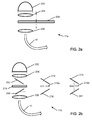
- FIGS. 2a-2d show schematic diagrams of exemplary embodiments of various light sources 11.
- the illustrated light sources are constructed to supply in normal color imaging mode visible illumination light yielding a substantially continuous spectral distribution.
- the light source maybe an arc lamp, a halogen lamp, one or more solid state sources (e.g. LEDs, semiconductor lasers) or any combination thereof and may be spectrally filtered or shaped (e.g. with bandpass filters, IR filters, etc.).
- the continuous spectrum may be produced as primary colors (RGB) either concurrently or sequentially, for example, using a rotating filter wheel.
- RGB primary colors
- light sources to be used with the system of the invention and described in detail below are configured to provide continuous, uninterrupted illumination in the blue and green parts of the visible spectrum and discontinuous red and/or NIR light.
- the blue and green parts of the visible spectrum may be optically filtered from the emission produced by a continuous source or produced directly by a narrow-band source (e.g. blue and green LEDs).
- the red and NIR light may also be produced by an arc lamp, a halogen lamp, a solid state source (e.g., red and NIR LEDs or lasers), or any combination thereof.
- a light source 11a includes an illuminator 202 producing visible and NIR light emission, a collimating lens 204, a filter wheel or reciprocating filter holder 208 that alternatingly transmits red and NIR light and continuously transmits green and blue light.
- a tunable electro-optic or acousto-optic filter may be used.
- the filtered light is focused by lens 206 onto light guide 17.
- the light source 11 b includes an illuminator 202 producing visible and NIR light emission and a collimating lens 204.
- a dichroic mirror 212 transmits green/blue light and reflects red/NIR light to another dichroic mirror 214 which transmits NIR light to NIR mirror 215 and reflects red light, or vice versa.
- the green/blue light can be further bandpass-filtered by filter 213.
- the reflected red and NIR light is chopped, for example, by chopper wheels 219a, 219b (which can be combined into a single chopper wheel) to produce temporally discontinuous illumination, which is then reflected by mirrors 216, 217 and combined with the green/blue light by dichroic mirror 218.
- the combined light is then focused by lens 206 onto light guide 17, as before.
- an illuminator 202a produces green and blue light emission which is collimated by a collimating lens 204a.
- separate illuminators 202b, 202c produce respective red and NIR light emissions which are collimated by corresponding collimating lenses 204b and 204c.
- the red and NIR light is chopped, for example, by chopper wheels 219a, 219b (which may also be combined into a single chopper wheel) to produce temporally discontinuous illumination, which is then combined with the green/blue illumination by dichroic mirrors 222, 228.
- the combined light is then focused by lens 206 onto light guide 17, as before.
- an illuminator 202a produces green and blue light emission which is collimated by a collimating lens 204a, as before.
- the separate illuminators 202d, 202e are here switched electrically to produce red and NIR light emissions with controlled timing.
- the red and NIR light sources 202d, 202e may be solid state light sources, such as LEDs or semiconductor lasers, which can be rapidly turned on and off with suitable, preferably electronic, switches. As described above with reference to FIG.
- the red and NIR illumination is collimated by corresponding collimating lenses 204b and 204c and combined with the green/blue illumination by dichroic mirrors 222, 228.
- the combined light is then focused by lens 206 onto light guide 17, as before.
- the alternating red and NIR illumination is synchronized with the image acquisition of the three-sensor camera such that red and NIR images are acquired by the camera synchronously with the red and NIR illumination of the endoscope.
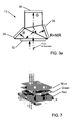
- FIG. 3a shows in more detail the three-sensor camera 13 of FIG. 1 , in particular the optical beam splitter used to direct red/NIR, green, and blue light to the three different image sensors 34, 36 and 38, respectively.
- the camera preferably also includes an excitation band blocking filter 32.
- the beam splitter may be made, for example, of a plurality of dichroic prisms, cube splitters, plate splitters or pellicle splitters.
- FIG. 3b shows the spectral composition of the light received from the endoscope according to FIG. 3a .
- Fig 3c illustrates the spectral composition of the light transmitted through the excitation band blocking filter 32 implemented as a notch filter 31 which blocks transmission of excitation light, while transmitting the other wavelengths in the visible and NIR spectral range.
- the transmission characteristic of this filter 32 may be designed to also block undesired NIR wavelengths interfering with the visible spectrum that may degrade the color image.
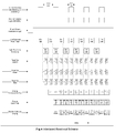
- FIG. 4 shows a timing diagram for a first exemplary embodiment of a simultaneous color and NIR imaging mode using, for example, a three-sensor camera.
- the camera sensors utilize an interlaced read-out format which represents an advantageous combination of spatial and temporal resolution for smooth display of motion.
- Any of the light sources illustrated in FIGS. 2a - 2d can be used with this embodiment.
- the light source provides continuous blue/green illumination and alternating red and NIR illumination.
- Half-frames are alternatingly exposed on the image sensors, i.e., a first field (half-frame) with even lines alternating with a second field (half-frame) with odd lines.
- a first field half-frame
- the sample or tissue is illuminated with full-spectrum color (RGB) during two field periods (33.3 ms) and with GB and NIR during a third field period.
- RGB full-spectrum color
- the missing red information is interpolated between the fields adjacent to the field with the NIR illumination.
- the blue and green image information is always available, thereby providing optimum and continuous luma information.
- the NIR image is generated from every sixth field in each half frame, wherein the missing lines are spatially interpolated. When the fluorescence field is displayed, the image is updated every three fields, with the displayed image interpolated between even and odd lines.
- the signal is outputted to a video monitor and may be displayed as two separate, simultaneous views (one color and one fluorescence) or as combined color and fluorescence image signals (e.g. by assigning the fluorescence signal a color that contrasts with the naturally occurring colors in the tissue).
- FIG. 5 shows a timing diagram for a second exemplary embodiment of a simultaneous color and NIR imaging mode.
- the camera sensors utilize a progressive scan sensor read-out format wherein a complete frame (G/B/R alternating with G/B/NIR) is read out during each field period.
- G/B/R complete frame
- Any of the light sources illustrated in FIGS. 2a - 2d can be used with this embodiment.
- the light source provides continuous blue/green illumination and alternating red and NIR illumination.
- one field period (16.7 ms) provides NIR illumination, followed by one field period (16.7 ms) of red illumination.
- the sample or tissue is illuminated with full-spectrum color (RGB) during one field period (16.7 ms) and with GB and NIR during a third field period.
- RGB full-spectrum color
- NIR full-spectrum color
- a full visible spectrum color image is available at every pixel, in every other frame.
- the blue and green information is acquired directly, whereas the red information is interpolated between adjacent frames.
- no spatial interpolation is required.
- Further image processing and display can be implemented in a manner similar to that described in previous embodiments.
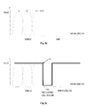
- FIG. 6 shows a timing diagram for a variant which is not an embodiment of the present invention, wherein both the green/blue illumination and the NIR illumination are continuous, while only the red illumination is modulated.
- half-frames are alternatingly exposed on the image sensors, i.e., a first field (half-frame) with even lines alternating with a second field (half-frame) with odd lines.
- one field period (16.7 ms) provides (NIR+GB) illumination (red illumination switched off), followed by two field periods (33.3 ms) of (NIR+RGB).
- the NIR image signal is small compared to the red reflected signal, it will not significantly affect the overall visible (RGB) image, so that the color image may be generated by conventional color image processing without correction. Otherwise the NIR contribution obtained in the red image channel when the red illumination is switched off may be subtracted from the (NIR+R) image data by spatial and temporal interpolation to obtain the red image signal, as shown in the second to last lien in the timing diagram of FIG. 6 .
- sensors with a progressive scan image sensor readout similar to those illustrated in FIG. 5 could be used with RGB and (RGB+IR) image acquisition in alternate frames.
- the green/blue illumination as well as the red illumination are continuous, whereas the NIR illumination is modulated.
- This timing scheme can be best applied if the red and NIR image signals have approximately the same magnitude.
- the light source provides uninterrupted illumination with full visible spectrum and intermittent illumination with NIR light.
- the timing diagram is essentially the same as that depicted in FIG. 6 , with the NIR and the red illumination interchanged.
- the intermittent NIR illumination is synchronized to coincide with every 3 rd field with interlaced cameras and with every other field in progressive scan cameras. For every field in which NIR illumination is provided, the red image sensor will acquire a (R+NIR) image signal.
- the NIR image signal can be extracted from the (R+NIR) image signal by interpolation of the red signal value from the appropriate preceding and subsequent "red only” image fields and subtracting the red image signal from the (R+NIR) signal. Since the red and NIR image signals are of similar magnitude, such interpolation and subtraction will provide a reasonably accurate NIR image signal value.
- the color image is processed by using the acquired and interpolated values for the red image signal in combination with the blue and green image signals. The resulting color and NIR image information can then be displayed or recorded as described before.
- the NIR endoscopic imaging system can also be operated such that the light sources provides continuous illumination with either the full visible spectrum or the NIR spectrum and the camera acquires the corresponding color image or NIR (absorbance or fluorescence) image in a continuous fashion to provide high spatial resolution.
- the resulting video image of either individual illumination/imaging mode - color or NIR - can be subsequently displayed and/or recorded.
Description
- The invention is directed to medical imaging, in particular to a system and method for obtaining visible light images and near infrared light images from an area under observation, such as living tissue, and in particular for use in endoscopy.
- Near-infrared (NIR) imaging has been described in the literature for various clinical applications. Typically such an imaging modality utilizes a contrast agent (e.g. indocyanine green) that absorbs and/or fluoresces in the NIR. Such contrast agents may be conjugated to targeting molecules (e.g. antibodies) for disease detection. The contrast agents may be introduced into tissue intravenously or subcutaneously to image tissue structure and function (e.g. flow of blood/lymph/bile in vessels) that is not easily seen with standard visible light imaging technology.
- Independently of the clinical application, endoscopic NIR imaging devices typically include multiple imaging modes as a practical feature. For example, endoscopists utilize visible spectrum color for both visualization and navigation, and an endoscopic imaging device that offers NIR imaging typically provides a concurrent color image. Such concurrent imaging devices can be realized, for example, as follows:
- One conventional configuration utilizes spectral separation of the visible and the NIR light, with full color and NIR image signals acquired using separate sensors for the different color (e.g. red, green, and blue) and NIR spectral bands or a single color sensor with an integrated filter with filter elements transparent to the different spectral bands (e.g. red, green, blue and NIR). Thus, such multi-modality color and NIR imaging devices provide dedicated sensors or sensor pixels for each of the two imaging modes. Disadvantageously, this increases the number of image sensors in multi-sensor implementations or compromises image resolution when on the same sensor, specific sensor pixels are dedicated for NIR imaging while others are utilized for color imaging.
- Another conventional configuration utilizes a single monochrome image sensor for sequential imaging of the visible and NIR light. The object is hereby sequentially illuminated with light in the red, green, blue and NIR spectral bands, with separate image frames being acquired for each spectral band and composite color and NIR images being generated from the acquired image frames. However, this approach, where image frames are acquired sequentially at different times, can generate objectionable motion artifacts (i.e. color fringing and "rainbow effects") in the composite color and NIR images. These artifacts can be mitigated by increasing the acquisition or frame rate to more than, for example, 15 frames/second (fps), for example to 90 fps, or even 180 fps. Because of the high data transfer rate, high frame rates are difficult to implement for high definition images (e.g. 2 million pixels), or images having a large dynamic range (> 10 bits), thus limiting image size and/or resolution.
- Another configuration is known from document
JP 2002 000560 A - It would therefore be desirable to provide a system and a method for simultaneous acquisition of full-color visible light and NIR light images, which obviates the aforementioned disadvantages and does not compromise image resolution and/or introduce objectionable motion artifacts.
- A method for acquisition of NIR images and full-color images includes the steps of illuminating an area under observation with continuous blue/green light, and illuminating the area under observation with red light and NIR light, wherein at least one of the red light and NIR light are switched on and off periodically. The blue, green, red and NIR light returning from the area under observation is directed to one or more sensors which are configured to separately detect the blue light, the green light, and the combined red light /NIR light. The red light spectral component and the NIR light spectral component are determined separately from image signals of the combined red light /NIR light, in synchronism with the switched red and NIR light. A full-color reflectance image of the area under observation is rendered and displayed from the blue, green, and red light and an NIR image is likewise rendered and displayed from the NIR light.
- An imaging system for acquisition of NIR and full-color images includes a light source providing visible light and NIR light to an area under observation, a camera having one or more image sensors configured to separately detect blue and green light, and combined red and NIR light returned from the area under observation, and a controller in signal communication with the light source and the camera. The controller is configured to control the light source to continuously illuminate tissue with blue/green light and to illuminate the area under observation with red light and NIR light, wherein at least one of the red light and NIR light are switched on and off periodically in synchronism with the acquisition of the red and NIR images in the camera.
- The controller is further configured to determine from sensor signals representing the combined red light and NIR light separately the red light spectral component and the NIR light spectral component. The imaging system further includes a display receiving image signals corresponding to the blue light, the green light, and the separately determined red light spectral component and rendering therefrom a full-color visible light image of the area under observation. The display also receives the separately determined NIR light spectral component and renders therefrom an NIR image of the area under observation.
- The video imaging system may use a three-sensor color camera configured to continuously image the blue and green wavebands and intermittently image the red waveband, thus providing continuous, high quality luma information and a sufficiently continuous complete chroma to produce high quality video images of the area under observation, such as living tissue. In such a configuration, the red image sensor can be time-multiplexed to acquire both red and NIR images (i.e. the red image sensor alternately, and in rapid succession, images both red light for the color information required for the color image and NIR light for image information required for the NIR image). Such time-multiplexing may be coupled to (and synchronized with) the illumination source used to provide the NIR illumination (excitation for fluorescence) and the red light for color imaging. Image processing is then utilized to separate and process the resulting image signals appropriately.
- According to the invention, the area under observation is alternatingly illuminated with red light and NIR light. The duration of red light may be different from, preferably longer than, the duration of illumination with NIR light. The illumination may be switched at video field or frame rates.
- Fields captured by the image sensor and lacking the red light spectral component or the NIR light spectral component may be interpolated from temporally adjacent image fields that include a corresponding red light spectral component or NIR light spectral component. In one embodiment, the NIR light spectral component obtained in the absence of red light may be subtracted from the combined red light /NIR light to obtain the separate red light spectral component. This is advantageous in particular when the detected NIR signal has an intensity comparable to that of the red signal.
- In one embodiment, the light source may include an illuminator emitting a substantially constant intensity of visible light and NIR light over a continuous spectral range, and a plurality of movable filters disposed between the illuminator and the area under observation for transmitting temporally continuous blue/green light and temporally discontinuous red light and NIR light.
- In another embodiment, the light source may include an illuminator emitting a substantially constant intensity of visible light and NIR light over a continuous spectral range, first dichroic means for separating the visible light and NIR light into blue/green and red light and NIR light, shutter means for transforming the separated red light and NIR light into temporally discontinuous red light and discontinuous 5 NIR light, and second dichroic means for combining the blue/green light, the temporally discontinuous red light and the temporally discontinuous NIR light for transmission to the area under observation.
- In yet another embodiment, the light source may include a first illuminator emitting a substantially constant intensity of green and blue light, a second illuminator producing switched red light, a third illuminator producing switched NIR excitation light, and dichroic means for combining the switched red light and the switched NIR light with the green and blue light for transmission to the area under observation. The switched red light and the NIR light may be produced by interrupting a continuous intensity light beam of the red light and the NIR light by a shutter or chopper. Alternatively, the switched red light and the NIR light may be produced by electrically switching the second illuminator and the third illuminator on and off.
- The image sensors may employ an interlaced scan or a progressive scan.
- The imaging system may include an endoscope.
- The following figures depict certain illustrative embodiments of the invention which are to be understood as illustrative of the invention and not as limiting in any way.
-
FIG. 1 shows an endoscopic system according to one embodiment of the invention; -
FIGS. 2a-2d show various exemplary embodiments of a multimode light source to be used with the endoscopic system ofFIG. 1 ; -
FIG. 3a shows an exemplary dichroic prism employed by a 3-sensor color camera; -
FIG. 3b shows the optical transmission ranges for the spectral components separated by the dichroic prism ofFIG. 3a ; -
FIG. 3c shows the optical transmission range of a notch filter that blocks excitation light from entering the camera; -
FIG. 4 shows a timing diagram of a first embodiment for continuous illumination with green/blue light and alternating illumination with red/NIR light; -
FIG. 5 shows a timing diagram of a second embodiment for continuous illumination with green/blue light and alternating illumination with red/NIR light; -
FIG. 6 shows a timing diagram of continuous illumination with green/blue/NIR light and alternating illumination with red light; and -
FIG. 7 shows an exemplary CMOS sensor having stacked imaging layers and the corresponding spectral sensitivity of these layers. - Color video images are generally obtained with three-sensor color cameras where separate red, green and blue image sensors provide simultaneous contiguous arrays of red, green and blue pixel information. Full color video images are generated by combining the image information from all three sensors. Color fidelity (i.e. a true color rendition) is extremely important in medical imaging applications and all three sensors are used to provide complete color information.
- To understand the relative importance of color and spatial information in video images of human tissue, however, it is useful to consider information in such video images in terms of luma and chroma. Luma refers to the brightness information in the image and it is this information that provides the spatial detail that enables the viewer to recognize shapes. The spatial and temporal resolution of luma is consequently crucial to the perception of video image quality. Chroma refers to the color information in the video image. It is a property of human vision that fine detail variations in the chroma of image features are not easily perceived and that such variations are consequently less critical than fine detail variations in luma, in an overall assessment of image quality. It is for this reason that video encoding of chroma information is often sub-sampled.
- In video images of human tissue obtained with visible light, the structural details of the tissue are largely contained in the blue and green wavelength regions of the imaged light. Blue and green light tends to be reflected from the tissue surface, whereas red light tends to be highly scattered within the tissue. As a consequence, there is very little fine structural detail in the red light that reaches the red image sensor. It is also known from color science that human vision receives most of the spatial information from the green portion of the visible spectrum - i.e. green light information contributes disproportionately to the luma. The standard formula for calculating luma from gamma-corrected color components is Y' = 0.2126 R' + 0.7152 G' + 0.0722 B'. For this reason, spatial and/or temporal interpolation of the red component of video images of human tissue does not significantly affect perception of fine detail in those images.
- Similarly to red light, NIR light tends to be scattered in tissue causing NIR image features to be diffusely, rather than sharply defined. Furthermore, because the NIR image highlights areas of interest (i.e. the areas in which the contrast agent is localized), but does not provide the overall visualization or navigational information, it is desirable for a NIR endoscopic imaging device to provide a continuous color image and either a superimposed or side-by-side display of the NIR image information. In such a display the NIR light would also contribute less to the spatial information presented to observer.
-
FIG. 1 shows schematically an exemplary embodiment of a NIRendoscopic imaging system 10 which includes a multimodelight source 11 that provides both visible and NIR illumination, connected to anendoscope 12 by way of an illumination guide, for example afiber optic cable 17, suitable for transmission of both color and NIR illumination, acolor camera 13, illustrated here as having threedifferent sensors FIG. 3a ) for blue, green and red/NIR imaging, respectively, mounted to the endoscope image guide, and acamera controller 14 connected to thecamera 13 and thelight source 11 for controlling and synchronizing illumination and image acquisition.Controller 14 can also process the acquired visible and NIR images for display on amonitor 15 connected to thecontroller 14, for example, by acable 19. Images can be acquired in real time at selectable frame rates, such as video rates. -
FIGS. 2a-2d show schematic diagrams of exemplary embodiments of variouslight sources 11. The illustrated light sources are constructed to supply in normal color imaging mode visible illumination light yielding a substantially continuous spectral distribution. The light source maybe an arc lamp, a halogen lamp, one or more solid state sources (e.g. LEDs, semiconductor lasers) or any combination thereof and may be spectrally filtered or shaped (e.g. with bandpass filters, IR filters, etc.). The continuous spectrum may be produced as primary colors (RGB) either concurrently or sequentially, for example, using a rotating filter wheel. - In systems according to the present invention, light sources to be used with the system of the invention and described in detail below are configured to provide continuous, uninterrupted illumination in the blue and green parts of the visible spectrum and discontinuous red and/or NIR light. The blue and green parts of the visible spectrum may be optically filtered from the emission produced by a continuous source or produced directly by a narrow-band source (e.g. blue and green LEDs). The red and NIR light may also be produced by an arc lamp, a halogen lamp, a solid state source (e.g., red and NIR LEDs or lasers), or any combination thereof.
- Turning now to
FIG. 2a , in one embodiment alight source 11a includes anilluminator 202 producing visible and NIR light emission, acollimating lens 204, a filter wheel or reciprocatingfilter holder 208 that alternatingly transmits red and NIR light and continuously transmits green and blue light. Alternatively, a tunable electro-optic or acousto-optic filter may be used. The filtered light is focused bylens 206 ontolight guide 17. - Another embodiment of a
light source 11 b is schematically illustrated inFIG. 2b . Thelight source 11 b includes anilluminator 202 producing visible and NIR light emission and acollimating lens 204. Adichroic mirror 212 transmits green/blue light and reflects red/NIR light to anotherdichroic mirror 214 which transmits NIR light toNIR mirror 215 and reflects red light, or vice versa. The green/blue light can be further bandpass-filtered byfilter 213. The reflected red and NIR light is chopped, for example, bychopper wheels mirrors dichroic mirror 218. The combined light is then focused bylens 206 ontolight guide 17, as before. - In another embodiment of a
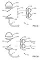
light source 11 c schematically illustrated inFIG. 2c , anilluminator 202a produces green and blue light emission which is collimated by acollimating lens 204a. Likewise,separate illuminators collimating lenses FIG. 2b , the red and NIR light is chopped, for example, bychopper wheels dichroic mirrors lens 206 ontolight guide 17, as before. - In yet another embodiment of a
light source 11 d schematically illustrated inFIG. 2d , anilluminator 202a produces green and blue light emission which is collimated by acollimating lens 204a, as before. However, unlike in the embodiment ofFIG. 2c , theseparate illuminators NIR light sources FIG. 2c , the red and NIR illumination is collimated by correspondingcollimating lenses dichroic mirrors lens 206 ontolight guide 17, as before. - The alternating red and NIR illumination is synchronized with the image acquisition of the three-sensor camera such that red and NIR images are acquired by the camera synchronously with the red and NIR illumination of the endoscope.
-
FIG. 3a shows in more detail the three-sensor camera 13 ofFIG. 1 , in particular the optical beam splitter used to direct red/NIR, green, and blue light to the threedifferent image sensors band blocking filter 32. The beam splitter may be made, for example, of a plurality of dichroic prisms, cube splitters, plate splitters or pellicle splitters.FIG. 3b shows the spectral composition of the light received from the endoscope according toFIG. 3a .Fig 3c illustrates the spectral composition of the light transmitted through the excitationband blocking filter 32 implemented as anotch filter 31 which blocks transmission of excitation light, while transmitting the other wavelengths in the visible and NIR spectral range. The transmission characteristic of thisfilter 32 may be designed to also block undesired NIR wavelengths interfering with the visible spectrum that may degrade the color image. -
FIG. 4 shows a timing diagram for a first exemplary embodiment of a simultaneous color and NIR imaging mode using, for example, a three-sensor camera. In this embodiment, the camera sensors utilize an interlaced read-out format which represents an advantageous combination of spatial and temporal resolution for smooth display of motion. Any of the light sources illustrated inFIGS. 2a - 2d can be used with this embodiment. The light source provides continuous blue/green illumination and alternating red and NIR illumination. Half-frames are alternatingly exposed on the image sensors, i.e., a first field (half-frame) with even lines alternating with a second field (half-frame) with odd lines. In the timing diagram ofFIG. 4 depicting a full frame rate of 30 fps, one field period (16.7 ms) provides NIR illumination, followed by two field periods (33.3 ms) of red illumination. Stated differently, the sample or tissue is illuminated with full-spectrum color (RGB) during two field periods (33.3 ms) and with GB and NIR during a third field period. For reconstructing the full-color visible image, the missing red information is interpolated between the fields adjacent to the field with the NIR illumination. The blue and green image information is always available, thereby providing optimum and continuous luma information. The NIR image is generated from every sixth field in each half frame, wherein the missing lines are spatially interpolated. When the fluorescence field is displayed, the image is updated every three fields, with the displayed image interpolated between even and odd lines. - In all the figures, the term "IR" is used instead of or interchangeably with "NIR."
- Once the color and NIR image data have been processed, the signal is outputted to a video monitor and may be displayed as two separate, simultaneous views (one color and one fluorescence) or as combined color and fluorescence image signals (e.g. by assigning the fluorescence signal a color that contrasts with the naturally occurring colors in the tissue).
-
FIG. 5 shows a timing diagram for a second exemplary embodiment of a simultaneous color and NIR imaging mode. In this embodiment, the camera sensors utilize a progressive scan sensor read-out format wherein a complete frame (G/B/R alternating with G/B/NIR) is read out during each field period. Any of the light sources illustrated inFIGS. 2a - 2d can be used with this embodiment. The light source provides continuous blue/green illumination and alternating red and NIR illumination. In the timing diagram ofFIG. 5 , one field period (16.7 ms) provides NIR illumination, followed by one field period (16.7 ms) of red illumination. Stated differently, the sample or tissue is illuminated with full-spectrum color (RGB) during one field period (16.7 ms) and with GB and NIR during a third field period. In this case, a full visible spectrum color image is available at every pixel, in every other frame. In the alternate frames, the blue and green information is acquired directly, whereas the red information is interpolated between adjacent frames. Unlike with the embodiment ofFIG. 4 , no spatial interpolation is required. Further image processing and display can be implemented in a manner similar to that described in previous embodiments. -
FIG. 6 shows a timing diagram for a variant which is not an embodiment of the present invention, wherein both the green/blue illumination and the NIR illumination are continuous, while only the red illumination is modulated. Like in the embodiment ofFIG. 4 , half-frames are alternatingly exposed on the image sensors, i.e., a first field (half-frame) with even lines alternating with a second field (half-frame) with odd lines. In the timing diagram ofFIG. 6 depicting a full frame rate of 30 fps, one field period (16.7 ms) provides (NIR+GB) illumination (red illumination switched off), followed by two field periods (33.3 ms) of (NIR+RGB). If the NIR image signal is small compared to the red reflected signal, it will not significantly affect the overall visible (RGB) image, so that the color image may be generated by conventional color image processing without correction. Otherwise the NIR contribution obtained in the red image channel when the red illumination is switched off may be subtracted from the (NIR+R) image data by spatial and temporal interpolation to obtain the red image signal, as shown in the second to last lien in the timing diagram ofFIG. 6 . Alternatively, sensors with a progressive scan image sensor readout similar to those illustrated inFIG. 5 could be used with RGB and (RGB+IR) image acquisition in alternate frames. - In yet another variant which is not an embodiment of the present invention (not illustrated in the drawings), the green/blue illumination as well as the red illumination are continuous, whereas the NIR illumination is modulated. This timing scheme can be best applied if the red and NIR image signals have approximately the same magnitude. In this variant, the light source provides uninterrupted illumination with full visible spectrum and intermittent illumination with NIR light. The timing diagram is essentially the same as that depicted in
FIG. 6 , with the NIR and the red illumination interchanged. The intermittent NIR illumination is synchronized to coincide with every 3rd field with interlaced cameras and with every other field in progressive scan cameras. For every field in which NIR illumination is provided, the red image sensor will acquire a (R+NIR) image signal. The NIR image signal can be extracted from the (R+NIR) image signal by interpolation of the red signal value from the appropriate preceding and subsequent "red only" image fields and subtracting the red image signal from the (R+NIR) signal. Since the red and NIR image signals are of similar magnitude, such interpolation and subtraction will provide a reasonably accurate NIR image signal value. The color image is processed by using the acquired and interpolated values for the red image signal in combination with the blue and green image signals. The resulting color and NIR image information can then be displayed or recorded as described before. - In any of the aforementioned embodiments, the NIR endoscopic imaging system can also be operated such that the light sources provides continuous illumination with either the full visible spectrum or the NIR spectrum and the camera acquires the corresponding color image or NIR (absorbance or fluorescence) image in a continuous fashion to provide high spatial resolution. The resulting video image of either individual illumination/imaging mode - color or NIR - can be subsequently displayed and/or recorded.
- By implementing color and NIR imaging as described in the aforementioned embodiments, it is possible to acquire and display full-color visible light and NIR light images at video rates without compromising image resolution and/or introducing objectionable motion artifacts. Furthermore, should any residual color fringing occur as a consequence of sharp edges moving rapidly across the visual field (e.g. with the discontinuous acquisition of red or NIR images), these relatively minor effects can be mitigated by temporal interpolation of the missing (red/NIR) video fields with minimum additional processing time.
- While the invention has been disclosed in connection with the preferred embodiments shown and described in detail, various modifications and improvements thereon will become readily apparent to those skilled in the art. For example, instead of using separate image sensors for G/B and R/NIR, or a single color sensor for RGB images and NIR fluorescence images, a single direct three-color RGB sensor image sensor with a stacked pixel design implemented in CMOS technology and commercially available from Foveon, Inc., San Jose, CA, may be used. Such sensor is schematically illustrated in
FIG. 7 . It will be understood that this sensor design can be extended to four colors by adding an NIR-sensitive layer. The red, green, blue and NIR images are hereby acquired at different depths in the image sensor. With a 4-layer sensor, multiplexing of the red and NIR illumination would be unnecessary. However, with a 3-layer sensor, the red and NIR illumination would still need to be multiplexed, as described above for a 3-sensor conventional camera. An appropriate barrier filter to block the NIR excitation light would also be required for fluorescence imaging applications. - While the invention has been illustrated and described in connection with currently preferred embodiments shown and described in detail, it is not intended to be limited to the details shown since various modifications and structural changes may be made without departing in any way from the scope of the present invention. The embodiments were chosen and described in order to explain the principles of the invention and practical application to thereby enable a person skilled in the art to best utilize the invention and various embodiments with various modifications as are suited to the particular use contemplated.
- What is claimed as new and desired to be protected by Letters Patent is set forth in the appended claims.
Claims (17)
- A method for acquisition of NIR and full-color images, comprising the steps of:continuously illuminating an area under observation with blue/green light, illuminating the area under observation with red light and NIR light, wherein the area under observation is alternatingly illuminated with red light and NIR light, and wherein the method further comprises the steps of:directing blue and green reflectance light and combined red reflectance light / detected NIR light to one or more sensors configured to separately detect the blue reflectance light, the green reflectance light, and the red reflectance light / detected NIR light, wherein the red reflectance light / detected NIR light is detected in synchronism with the switched red light and NIR light,determining from image signals of the combined red reflectance light / detected NIR light separately the red reflectance light spectral component and the detected NIR light spectral component,displaying a full-color image of the area under observation from the blue and green reflectance light and the separately determined red light spectral component, anddisplaying an NIR image from the detected NIR light spectral component.
- The method of claim 1, wherein either:a) a time duration of red light illumination is different from a time duration of NIR light illumination, orb) a time duration of red light illumination is different from a time duration of NIR light illumination, the time duration of red light illumination being longer than the time duration of NIR light illumination, orc) a time duration of red light illumination is substantially identical to a time duration of NIR light illumination.
- The method of claim 1, wherein the red light or NIR light, or both, are switched at video rates.
- The method of claim 1, wherein image fields lacking the red reflectance light spectral component or the detected NIR light spectral component are interpolated from temporally adjacent image fields that include a corresponding red reflectance light spectral component or detected NIR light spectral component.
- The method of claim 1, wherein spatial information of the area under observation is primarily derived from the blue reflectance light and the green reflectance light.
- An imaging system for acquisition of NIR images and full-color images comprising:a light source for providing visible light and NIR light to an area under observation,a camera having one or more image sensors configured to separately detect blue reflectance light, green reflectance light, and combined red reflectance light / detected NIR light returned from the area under observation,a controller in signal communication with the light source and the camera configured to control the light source to continuously illuminate the area under observation with blue/green light, and to illuminate the area under observation with red light / NIR light, wherein the area under observation is alternatingly illuminated by the light source with the red light and NIR light, andthe controller further being configured to determine from the combined red reflectance light / detected NIR light separately the red reflectance light spectral component and the detected NIR light spectral component in synchronism with the switched red and NIR light, anda display configured to receive image signals corresponding to the blue reflectance light, the green reflectance light, and the separately determined red reflectance light spectral component and to render therefrom a full-color reflectance image of the area under observation, the display further configured to receive the separately determined NIR fluorescence light spectral component and to render therefrom an NIR image of the area under observation.
- The imaging system of claim 6, wherein the light source comprises an illuminator configured to emit a substantially constant intensity of visible light and NIR light over a continuous spectral range, and
a plurality of filters disposed between the illuminator and the area under observation for transmitting temporally continuous blue/green light and temporally discontinuous red light and discontinuous NIR light. - The imaging system of claim 6, wherein the light source comprises an illuminator configured to emit a substantially constant intensity of visible light and NIR light over a continuous spectral range,
first dichroic means for separating the visible light and NIR light into blue/green and red light and NIR light,
shutter means for transforming the separated red light and NIR light into temporally discontinuous red light and discontinuous NIR light, and
second dichroic means for combining the blue/green light, the temporally discontinuous red light and the temporally discontinuous NIR light for transmission to the area under observation. - The imaging system of claim 6, wherein the light source comprises a first illuminator configured to emit a substantially constant intensity of green and blue light,
a second illuminator for producing switched red light,
a third illuminator for producing switched NIR light, and
dichroic means for combining the switched red light and the switched NIR light with the green and blue light for transmission to the area under observation. - The imaging system of claim 9, wherein the switched red light and the NIR light are produced by interrupting a continuous intensity light beam of the red light and the NIR light by a shutter or chopper, or
wherein the switched red light and the NIR light are produced by electrically switching the second illuminator and the third illuminator on and off. - The imaging system of claim 6, wherein the image sensors employ an interlaced scan, or
wherein the image sensors employ a progressive scan. - The imaging system of claim 6, further comprising a dichroic prism assembly configured to spectrally separate the blue reflectance light, the green reflectance light and the combined red reflectance light / detected NIR light returned from the area under observation and to direct the separated light to different exit faces of the dichroic prism assembly, wherein the one or more image sensors comprise three image sensors, each mounted on a different exit face.
- The imaging system of claim 6, wherein the one or more image sensors comprise a single image sensor having pixels, each pixel responsive to one of the blue reflectance light, the green reflectance light and the combined red reflectance light / detected NIR light returned from the area under observation.
- The imaging system of claim 13, wherein the single image sensor comprises a mosaic blue/green/red-NIR filter array disposed before the sensor pixels.
- The imaging system of claim 6, wherein the one or more image sensors comprise a single image sensor having a plurality of stacked layers, each layer having pixels responsive to one of the blue reflectance light, the green reflectance light and the combined red reflectance light / detected NIR light returned from the area under observation.
- The imaging system of claim 6, wherein the imaging system is configured as an endoscope.
- The imaging system of claim 9, wherein the detected NIR light is fluorescence light.
Priority Applications (1)
| Application Number | Priority Date | Filing Date | Title |
|---|---|---|---|
| EP16186321.2A EP3117765B1 (en) | 2008-03-18 | 2009-03-18 | Imaging system for combined full-colour reflectance and near-infrared imaging |
Applications Claiming Priority (2)
| Application Number | Priority Date | Filing Date | Title |
|---|---|---|---|
| US3751408P | 2008-03-18 | 2008-03-18 | |
| PCT/US2009/037506 WO2009117483A1 (en) | 2008-03-18 | 2009-03-18 | Imaging system for combined full-color reflectance and near-infrared imaging |
Related Child Applications (1)
| Application Number | Title | Priority Date | Filing Date |
|---|---|---|---|
| EP16186321.2A Division EP3117765B1 (en) | 2008-03-18 | 2009-03-18 | Imaging system for combined full-colour reflectance and near-infrared imaging |
Publications (3)
| Publication Number | Publication Date |
|---|---|
| EP2268194A1 EP2268194A1 (en) | 2011-01-05 |
| EP2268194A4 EP2268194A4 (en) | 2014-08-20 |
| EP2268194B1 true EP2268194B1 (en) | 2016-08-31 |
Family
ID=41091235
Family Applications (2)
| Application Number | Title | Priority Date | Filing Date |
|---|---|---|---|
| EP09721252.6A Active EP2268194B1 (en) | 2008-03-18 | 2009-03-18 | Imaging system for combined full-color reflectance and near-infrared imaging |
| EP16186321.2A Active EP3117765B1 (en) | 2008-03-18 | 2009-03-18 | Imaging system for combined full-colour reflectance and near-infrared imaging |
Family Applications After (1)
| Application Number | Title | Priority Date | Filing Date |
|---|---|---|---|
| EP16186321.2A Active EP3117765B1 (en) | 2008-03-18 | 2009-03-18 | Imaging system for combined full-colour reflectance and near-infrared imaging |
Country Status (10)
| Country | Link |
|---|---|
| US (3) | US9173554B2 (en) |
| EP (2) | EP2268194B1 (en) |
| JP (4) | JP5231625B2 (en) |
| KR (1) | KR101517264B1 (en) |
| CN (1) | CN102036599B (en) |
| BR (1) | BRPI0906187A2 (en) |
| HK (1) | HK1157169A1 (en) |
| MX (1) | MX2010010292A (en) |
| RU (1) | RU2510235C2 (en) |
| WO (1) | WO2009117483A1 (en) |
Families Citing this family (154)
| Publication number | Priority date | Publication date | Assignee | Title |
|---|---|---|---|---|
| CA2447262A1 (en) | 2001-05-17 | 2002-11-21 | Xenogen Corporation | Method and apparatus for determining target depth, brightness and size within a body region |
| US20070122344A1 (en) | 2005-09-02 | 2007-05-31 | University Of Rochester Medical Center Office Of Technology Transfer | Intraoperative determination of nerve location |
| US20080161744A1 (en) | 2006-09-07 | 2008-07-03 | University Of Rochester Medical Center | Pre-And Intra-Operative Localization of Penile Sentinel Nodes |
| US8498695B2 (en) | 2006-12-22 | 2013-07-30 | Novadaq Technologies Inc. | Imaging system with a single color image sensor for simultaneous fluorescence and color video endoscopy |
| US8406860B2 (en) | 2008-01-25 | 2013-03-26 | Novadaq Technologies Inc. | Method for evaluating blush in myocardial tissue |
| KR101517264B1 (en) | 2008-03-18 | 2015-05-04 | 노바다크 테크놀러지즈 인코포레이티드 | Imaging system for combined full-color reflectance and near-infrared imaging |
| US10219742B2 (en) | 2008-04-14 | 2019-03-05 | Novadaq Technologies ULC | Locating and analyzing perforator flaps for plastic and reconstructive surgery |
| US8228368B2 (en) | 2008-04-26 | 2012-07-24 | Intuitive Surgical Operations, Inc. | Augmented stereoscopic visualization for a surgical robot using a captured fluorescence image and captured stereoscopic visible images |
| EP3372250B1 (en) | 2008-05-02 | 2019-12-25 | Novadaq Technologies ULC | Methods for production and use of substance-loaded erythrocytes for observation and treatment of microvascular hemodynamics |
| US9042967B2 (en) | 2008-05-20 | 2015-05-26 | University Health Network | Device and method for wound imaging and monitoring |
| WO2009158662A2 (en) * | 2008-06-26 | 2009-12-30 | Global Rainmakers, Inc. | Method of reducing visibility of illimination while acquiring high quality imagery |
| JP2010051538A (en) * | 2008-08-28 | 2010-03-11 | Panasonic Corp | Imaging apparatus |
| US10492671B2 (en) | 2009-05-08 | 2019-12-03 | Novadaq Technologies ULC | Near infra red fluorescence imaging for visualization of blood vessels during endoscopic harvest |
| DE102009025662A1 (en) | 2009-06-17 | 2010-12-23 | Karl Storz Gmbh & Co. Kg | Method and apparatus for controlling a multicolor output of an image of a medical object |
| US10130246B2 (en) | 2009-06-18 | 2018-11-20 | Endochoice, Inc. | Systems and methods for regulating temperature and illumination intensity at the distal tip of an endoscope |
| US10524645B2 (en) | 2009-06-18 | 2020-01-07 | Endochoice, Inc. | Method and system for eliminating image motion blur in a multiple viewing elements endoscope |
| US9474440B2 (en) | 2009-06-18 | 2016-10-25 | Endochoice, Inc. | Endoscope tip position visual indicator and heat management system |
| JP5507376B2 (en) * | 2010-07-28 | 2014-05-28 | 三洋電機株式会社 | Imaging device |
| US8996086B2 (en) | 2010-09-17 | 2015-03-31 | OptimumTechnologies, Inc. | Digital mapping system and method |
| US10663714B2 (en) | 2010-10-28 | 2020-05-26 | Endochoice, Inc. | Optical system for an endoscope |
| US9706908B2 (en) | 2010-10-28 | 2017-07-18 | Endochoice, Inc. | Image capture and video processing systems and methods for multiple viewing element endoscopes |
| JP5647882B2 (en) * | 2010-12-17 | 2015-01-07 | Hoya株式会社 | Endoscope processor |
| US20130258112A1 (en) * | 2010-12-21 | 2013-10-03 | Zamir Recognition Systems Ltd. | Visible light and ir hybrid digital camera |
| US10517464B2 (en) | 2011-02-07 | 2019-12-31 | Endochoice, Inc. | Multi-element cover for a multi-camera endoscope |
| KR20140000329A (en) | 2011-03-08 | 2014-01-02 | 노바다크 테크놀러지즈 인코포레이티드 | Full spectrum led illuminator |
| RU2564903C2 (en) * | 2011-04-25 | 2015-10-10 | Анатолий Александрович Ковалев | Method for combined exposure to multi-frequency laser exposures |
| US9795285B2 (en) * | 2011-07-07 | 2017-10-24 | Boston Scientific Scimed, Inc. | Imaging system for endoscope |
| US8784301B2 (en) | 2011-08-12 | 2014-07-22 | Intuitive Surgical Operations, Inc. | Image capture unit and method with an extended depth of field |
| US8672838B2 (en) | 2011-08-12 | 2014-03-18 | Intuitive Surgical Operations, Inc. | Image capture unit in a surgical instrument |
| US8684914B2 (en) * | 2011-08-12 | 2014-04-01 | Intuitive Surgical Operations, Inc. | Image capture unit and an imaging pipeline with enhanced color performance in a surgical instrument and method |
| US8734328B2 (en) | 2011-08-12 | 2014-05-27 | Intuitive Surgical Operations, Inc. | Increased resolution and dynamic range image capture unit in a surgical instrument and method |
| US8764633B2 (en) | 2011-08-12 | 2014-07-01 | Intuitive Surgical Operations, Inc. | Feature differentiation image capture unit and method in a surgical instrument |
| CN103476324B (en) * | 2011-11-11 | 2015-09-02 | 奥林巴斯医疗株式会社 | Chrominance signal transmitting device, wireless imaging transmission system and dispensing device |
| RU2616653C2 (en) * | 2012-06-05 | 2017-04-18 | Хайпермед Имэджинг, Инк. | Methods and device for coaxial image forming with multiple wavelengths |
| US10278585B2 (en) | 2012-06-21 | 2019-05-07 | Novadaq Technologies ULC | Quantification and analysis of angiography and perfusion |
| JP6157135B2 (en) * | 2013-02-07 | 2017-07-05 | オリンパス株式会社 | Light source imaging device |
| WO2014153057A1 (en) * | 2013-03-14 | 2014-09-25 | James Olson | Improved multi-channel camera system |
| US9628724B2 (en) | 2013-03-14 | 2017-04-18 | Drs Network & Imaging Systems, Llc | Method and system for providing scene data in a video stream |
| WO2014144492A1 (en) | 2013-03-15 | 2014-09-18 | Drs Rsta, Inc. | Method of shutterless non-uniformity correction for infrared imagers |
| EP2967299B1 (en) * | 2013-03-15 | 2022-11-30 | Stryker Corporation | Endoscopic light source and imaging system |
| US10595714B2 (en) | 2013-03-28 | 2020-03-24 | Endochoice, Inc. | Multi-jet controller for an endoscope |
| US9636003B2 (en) | 2013-06-28 | 2017-05-02 | Endochoice, Inc. | Multi-jet distributor for an endoscope |
| US20140307055A1 (en) | 2013-04-15 | 2014-10-16 | Microsoft Corporation | Intensity-modulated light pattern for active stereo |
| DK2988654T3 (en) * | 2013-04-23 | 2020-09-07 | Cedars Sinai Medical Center | SYSTEMS AND METHODS FOR THE SAME TAKING OF AN IMAGE IN VISIBLE LIGHT AND AN INFRARED LIGHT IMAGE FROM FLUROPHORES |
| US9407838B2 (en) | 2013-04-23 | 2016-08-02 | Cedars-Sinai Medical Center | Systems and methods for recording simultaneously visible light image and infrared light image from fluorophores |
| JP6669647B2 (en) | 2013-05-07 | 2020-03-18 | エンドチョイス インコーポレイテッドEndochoice, Inc. | White balance correction device for use with endoscope and method of performing white balance correction |
| US9949623B2 (en) | 2013-05-17 | 2018-04-24 | Endochoice, Inc. | Endoscope control unit with braking system |
| WO2014192563A1 (en) * | 2013-05-29 | 2014-12-04 | オリンパスメディカルシステムズ株式会社 | Endoscope system |
| KR101514204B1 (en) | 2013-07-12 | 2015-04-23 | 한국전기연구원 | Apparatus and method for detecting NIR fluorescence at Sentinel Lymph Node |
| US10165972B2 (en) | 2013-07-12 | 2019-01-01 | Inthesmart Co., Ltd. | Apparatus and method for detecting NIR fluorescence at sentinel lymph node |
| US10064541B2 (en) | 2013-08-12 | 2018-09-04 | Endochoice, Inc. | Endoscope connector cover detection and warning system |
| US9943218B2 (en) | 2013-10-01 | 2018-04-17 | Endochoice, Inc. | Endoscope having a supply cable attached thereto |
| WO2015070096A1 (en) * | 2013-11-08 | 2015-05-14 | Drs Network & Imaging Systems, Llc | Method and system for output of dual video stream via a single parallel digital video interface |
| US9332235B2 (en) * | 2013-12-10 | 2016-05-03 | Visera Technologies Company Limited | Imaging capture apparatus having plurality of image sensors generating respective image signals based on emitted light areas |
| US9968242B2 (en) | 2013-12-18 | 2018-05-15 | Endochoice, Inc. | Suction control unit for an endoscope having two working channels |
| WO2015112747A2 (en) | 2014-01-22 | 2015-07-30 | Endochoice, Inc. | Image capture and video processing systems and methods for multiple viewing element endoscopes |
| JP5968944B2 (en) | 2014-03-31 | 2016-08-10 | 富士フイルム株式会社 | Endoscope system, processor device, light source device, operation method of endoscope system, operation method of processor device, operation method of light source device |
| WO2015156153A1 (en) * | 2014-04-08 | 2015-10-15 | オリンパス株式会社 | Fluorescence endoscopy system |
| US11234581B2 (en) | 2014-05-02 | 2022-02-01 | Endochoice, Inc. | Elevator for directing medical tool |
| JP6254907B2 (en) * | 2014-05-30 | 2017-12-27 | 株式会社モリタ製作所 | Laser light guide system |
| US20150356944A1 (en) * | 2014-06-09 | 2015-12-10 | Optoma Corporation | Method for controlling scene and electronic apparatus using the same |
| EP4345527A2 (en) | 2014-07-21 | 2024-04-03 | EndoChoice, Inc. | Multi-focal, multi-camera endoscope systems |
| PT3171765T (en) | 2014-07-24 | 2021-10-27 | Univ Health Network | Collection and analysis of data for diagnostic purposes |
| CN111990946A (en) | 2014-08-29 | 2020-11-27 | 恩多巧爱思股份有限公司 | System and method for varying the stiffness of an endoscope insertion tube |
| CN107209118B (en) * | 2014-09-29 | 2021-05-28 | 史赛克欧洲运营有限公司 | Imaging of target fluorophores in biological materials in the presence of autofluorescence |
| CN107427247B (en) | 2014-10-09 | 2021-06-04 | 史赛克欧洲运营有限公司 | Quantification of absolute blood flow in tissue using fluorescence-mediated photoplethysmography |
| EP3232899A4 (en) * | 2014-12-18 | 2018-11-07 | EndoChoice, Inc. | Multiple viewing element endoscope system having multiple sensor motion synchronization |
| WO2016100173A1 (en) | 2014-12-18 | 2016-06-23 | Endochoice, Inc. | System and method for processing video images generated by a multiple viewing elements endoscope |
| WO2016112034A2 (en) | 2015-01-05 | 2016-07-14 | Endochoice, Inc. | Tubed manifold of a multiple viewing elements endoscope |
| JP6385465B2 (en) * | 2015-01-21 | 2018-09-05 | オリンパス株式会社 | Endoscope device |
| JP6377181B2 (en) * | 2015-01-22 | 2018-08-22 | オリンパス株式会社 | Imaging device |
| US10376181B2 (en) | 2015-02-17 | 2019-08-13 | Endochoice, Inc. | System for detecting the location of an endoscopic device during a medical procedure |
| US10078207B2 (en) | 2015-03-18 | 2018-09-18 | Endochoice, Inc. | Systems and methods for image magnification using relative movement between an image sensor and a lens assembly |
| JP6025130B2 (en) | 2015-03-23 | 2016-11-16 | パナソニックIpマネジメント株式会社 | Endoscope and endoscope system |
| US11206987B2 (en) * | 2015-04-03 | 2021-12-28 | Suzhou Caring Medical Co., Ltd. | Method and apparatus for concurrent imaging at visible and infrared wavelengths |
| US10401611B2 (en) | 2015-04-27 | 2019-09-03 | Endochoice, Inc. | Endoscope with integrated measurement of distance to objects of interest |
| JP6561571B2 (en) * | 2015-05-12 | 2019-08-21 | ソニー株式会社 | Medical imaging apparatus, imaging method, and imaging apparatus |
| US10516865B2 (en) | 2015-05-17 | 2019-12-24 | Endochoice, Inc. | Endoscopic image enhancement using contrast limited adaptive histogram equalization (CLAHE) implemented in a processor |
| JP6451494B2 (en) * | 2015-05-19 | 2019-01-16 | 株式会社島津製作所 | Imaging device |
| WO2017007791A1 (en) * | 2015-07-06 | 2017-01-12 | Scinovia Corp. | Fluorescence based flow imaging and measurements |
| US10598914B2 (en) * | 2015-07-14 | 2020-03-24 | Massachusetts Institute Of Technology | Enhancement of video-rate fluorescence imagery collected in the second near-infrared optical window |
| US10579891B2 (en) | 2015-08-10 | 2020-03-03 | AI Biomed Corp | Optical overlay device |
| JP6169310B1 (en) * | 2015-10-22 | 2017-07-26 | オリンパス株式会社 | Endoscope system |
| US20170119474A1 (en) | 2015-10-28 | 2017-05-04 | Endochoice, Inc. | Device and Method for Tracking the Position of an Endoscope within a Patient's Body |
| AU2016351730B2 (en) | 2015-11-13 | 2019-07-11 | Novadaq Technologies Inc. | Systems and methods for illumination and imaging of a target |
| US10898062B2 (en) | 2015-11-24 | 2021-01-26 | Endochoice, Inc. | Disposable air/water and suction valves for an endoscope |
| EP3407109B1 (en) * | 2016-01-19 | 2023-11-08 | Sony Olympus Medical Solutions Inc. | Medical light source device and medical observation system |
| EP3408654B1 (en) | 2016-01-26 | 2022-08-03 | Stryker European Operations Limited | Fluorescence imaging system and method for fluorescence imaging |
| JP2019507628A (en) | 2016-02-24 | 2019-03-22 | エンドチョイス インコーポレイテッドEndochoice, Inc. | Circuit board assembly for multiple view element endoscopes using CMOS sensors |
| US10292570B2 (en) | 2016-03-14 | 2019-05-21 | Endochoice, Inc. | System and method for guiding and tracking a region of interest using an endoscope |
| JP6522539B2 (en) * | 2016-03-18 | 2019-05-29 | 富士フイルム株式会社 | Endoscope system and method of operating the same |
| US10690904B2 (en) | 2016-04-12 | 2020-06-23 | Stryker Corporation | Multiple imaging modality light source |
| USD916294S1 (en) | 2016-04-28 | 2021-04-13 | Stryker European Operations Limited | Illumination and imaging device |
| JP6168436B1 (en) * | 2016-09-21 | 2017-07-26 | パナソニックIpマネジメント株式会社 | Endoscope and endoscope system |
| JP6132251B1 (en) * | 2016-05-19 | 2017-05-24 | パナソニックIpマネジメント株式会社 | Endoscope and endoscope system |
| US10122975B2 (en) | 2016-05-19 | 2018-11-06 | Panasonic Intellectual Property Management Co., Ltd. | Endoscope and endoscope system |
| JP6626783B2 (en) * | 2016-06-02 | 2019-12-25 | Hoya株式会社 | Image processing apparatus and electronic endoscope system |
| US10869645B2 (en) | 2016-06-14 | 2020-12-22 | Stryker European Operations Limited | Methods and systems for adaptive imaging for low light signal enhancement in medical visualization |
| EP3472570A4 (en) | 2016-06-16 | 2020-02-12 | Novadaq Technologies ULC | Closed cavity adjustable sensor mount systems and methods |
| EP3918972B1 (en) | 2016-06-21 | 2023-10-25 | EndoChoice, Inc. | Endoscope system with multiple connection interfaces to interface with different video data signal sources |
| WO2017223378A1 (en) | 2016-06-23 | 2017-12-28 | Li-Cor, Inc. | Complementary color flashing for multichannel image presentation |
| WO2018020560A1 (en) * | 2016-07-25 | 2018-02-01 | オリンパス株式会社 | Image processing device, image processing method, and program |
| US11911003B2 (en) | 2016-09-09 | 2024-02-27 | Intuitive Surgical Operations, Inc. | Simultaneous white light and hyperspectral light imaging systems |
| JP6388237B2 (en) * | 2016-09-27 | 2018-09-12 | パナソニックIpマネジメント株式会社 | 4-color prism |
| EP3508109B1 (en) * | 2016-10-07 | 2024-02-14 | Sony Olympus Medical Solutions Inc. | Medical imaging apparatus and medical observation system |
| US11558677B2 (en) * | 2016-11-10 | 2023-01-17 | Telefonaktiebolaget Lm Ericsson (Publ) | Resource segmentation to improve delivery performance |
| CN106595860B (en) * | 2016-11-27 | 2018-12-14 | 苏州国科美润达医疗技术有限公司 | Multi-optical spectrum imaging system |
| NL2017973B1 (en) | 2016-12-09 | 2018-06-19 | Quest Photonic Devices B V | Dichroic prism assembly with four or five channels |
| EP4242743A3 (en) | 2017-02-10 | 2023-10-18 | Stryker European Operations Limited | Open-field handheld fluorescence imaging systems and methods |
| NL2018494B1 (en) | 2017-03-09 | 2018-09-21 | Quest Photonic Devices B V | Method and apparatus using a medical imaging head for fluorescent imaging |
| US11259892B2 (en) * | 2017-03-10 | 2022-03-01 | Asensus Surgical Us, Inc. | Instrument for optical tissue interrogation |
| US20200397266A1 (en) * | 2017-03-10 | 2020-12-24 | Transenterix Surgical, Inc. | Apparatus and method for enhanced tissue visualization |
| CN110381804B (en) * | 2017-03-10 | 2022-05-17 | 索尼奥林巴斯医疗解决方案公司 | Endoscopic apparatus |
| JP6939000B2 (en) * | 2017-03-23 | 2021-09-22 | 株式会社Jvcケンウッド | Imaging device and imaging method |
| WO2018176493A1 (en) * | 2017-04-01 | 2018-10-04 | SZ DJI Technology Co., Ltd. | Low-profile multi-band hyperspectral imaging for machine vision |
| JP6388240B2 (en) * | 2017-04-06 | 2018-09-12 | パナソニックIpマネジメント株式会社 | Optical device |
| WO2018198117A1 (en) | 2017-04-24 | 2018-11-01 | Ramot At Tel-Aviv University Ltd. | Multi-frequency infrared imaging based on frequency conversion |
| JP7107308B2 (en) * | 2017-05-22 | 2022-07-27 | ソニーグループ株式会社 | Observation system and light source controller |
| WO2018225122A1 (en) * | 2017-06-05 | 2018-12-13 | オリンパス株式会社 | Endoscope device |
| CA3064779A1 (en) * | 2017-09-15 | 2019-03-21 | Kent Imaging | Hybrid visible and near infrared imaging with an rgb color filter array sensor |
| KR101998592B1 (en) * | 2017-09-20 | 2019-07-10 | 인더스마트 주식회사 | Apparatus and method for detecting near-infrared fluorescence |
| JP6834907B2 (en) * | 2017-10-25 | 2021-02-24 | トヨタ自動車株式会社 | Imaging method |
| CN111971604B (en) | 2018-03-28 | 2022-05-17 | 索尼公司 | Rigid mirror optical system, imaging device, and endoscope system |
| KR102190398B1 (en) | 2018-05-29 | 2020-12-11 | 한국전기연구원 | System and method for providing visible ray image and near-infrared ray image, using a single color camera and capable of those images simultaneously |
| JP6865718B2 (en) * | 2018-07-19 | 2021-04-28 | パナソニックi−PROセンシングソリューションズ株式会社 | Endoscope |
| JP6865719B2 (en) * | 2018-07-19 | 2021-04-28 | パナソニックi−PROセンシングソリューションズ株式会社 | Medical light microscope |
| JP7183616B2 (en) * | 2018-08-02 | 2022-12-06 | ソニーグループ株式会社 | IMAGING DEVICE, SIGNAL PROCESSING DEVICE, SIGNAL PROCESSING METHOD AND PROGRAM |
| CN109124586A (en) * | 2018-08-15 | 2019-01-04 | 南京航空航天大学 | A kind of multi-mode fluorescence endoscopic Real Time Image System |
| CN109363768A (en) * | 2018-10-10 | 2019-02-22 | 南京诺源医疗器械有限公司 | 785nm wavelength light source near-infrared fluorescence imaging surgery guides system |
| CN109222910A (en) * | 2018-10-10 | 2019-01-18 | 南京诺源医疗器械有限公司 | Fluorescence detection device |
| WO2020096894A1 (en) * | 2018-11-05 | 2020-05-14 | Medivators Inc. | Endoscope fluorescence inspection device |
| CN113164054A (en) * | 2018-11-30 | 2021-07-23 | 直观外科手术操作公司 | Medical imaging system and method |
| JP7080195B2 (en) * | 2019-02-19 | 2022-06-03 | 富士フイルム株式会社 | Endoscope system |
| WO2020176906A1 (en) * | 2019-02-26 | 2020-09-03 | Ai Biomed Corp. | Tissue detection system and methods for use thereof |
| US11540883B2 (en) * | 2019-03-08 | 2023-01-03 | Thomas Jefferson University | Virtual reality training for medical events |
| CN109864691A (en) * | 2019-04-04 | 2019-06-11 | 济南显微智能科技有限公司 | A kind of double tracer fluorescence endoscopes |
| US11931009B2 (en) | 2019-06-20 | 2024-03-19 | Cilag Gmbh International | Offset illumination of a scene using multiple emitters in a hyperspectral imaging system |
| US11716533B2 (en) * | 2019-06-20 | 2023-08-01 | Cilag Gmbh International | Image synchronization without input clock and data transmission clock in a pulsed fluorescence imaging system |
| US11589819B2 (en) * | 2019-06-20 | 2023-02-28 | Cilag Gmbh International | Offset illumination of a scene using multiple emitters in a laser mapping imaging system |
| US11892403B2 (en) * | 2019-06-20 | 2024-02-06 | Cilag Gmbh International | Image synchronization without input clock and data transmission clock in a pulsed fluorescence imaging system |
| CN111528770B (en) * | 2019-06-20 | 2021-01-12 | 深圳迈瑞生物医疗电子股份有限公司 | Endoscope imaging system, image processing method, and readable storage medium |
| EP3779554B1 (en) * | 2019-08-14 | 2024-01-17 | Leica Instruments (Singapore) Pte. Ltd. | Optical beam splitter assembly, camera head, and microscope assembly |
| CN110672551B (en) * | 2019-09-10 | 2021-11-19 | 中国科学院上海技术物理研究所 | Micro-area image spectrum analysis method for important biological resources |
| CN110547752A (en) * | 2019-09-16 | 2019-12-10 | 北京数字精准医疗科技有限公司 | Endoscope system, mixed light source, video acquisition device and image processor |
| CA3175464A1 (en) * | 2020-04-06 | 2021-10-14 | Boston Scientific Scimed, Inc. | Image processing systems and methods of using the same |
| EP4193329A1 (en) * | 2020-09-25 | 2023-06-14 | Boston Scientific Scimed, Inc. | Color extrapolation from monochrome image sensor |
| TW202213978A (en) * | 2020-09-28 | 2022-04-01 | 大陸商廣州印芯半導體技術有限公司 | Image sensing device and image sensing method |
| JP7041226B2 (en) * | 2020-10-19 | 2022-03-23 | パナソニックi-PROセンシングソリューションズ株式会社 | Medical optical microscope |
| EP4271248A1 (en) | 2020-12-30 | 2023-11-08 | Stryker Corporation | Contrast enhancement for medical imaging |
| US11895393B1 (en) | 2021-06-23 | 2024-02-06 | Verily Life Sciences Llc | Use of intermediate frames to capture and adjust low frame-rate, single-light source images |
| CN114397255B (en) * | 2021-11-12 | 2023-09-01 | 中国科学院西安光学精密机械研究所 | Wide-spectrum high-resolution video spectrum imaging system and method |
| CN114125319A (en) * | 2021-11-30 | 2022-03-01 | 维沃移动通信有限公司 | Image sensor, camera module, image processing method and device and electronic equipment |
| US20230421912A1 (en) | 2022-06-23 | 2023-12-28 | Stryker Corporation | Systems and methods for multi-spectral imaging with a non-mechanical adjustable aperture |
| US20240125703A1 (en) | 2022-09-16 | 2024-04-18 | Stryker Corporation | Systems and methods for quantifying user observed visualization of fluorescence imaging agents |
Family Cites Families (441)
| Publication number | Priority date | Publication date | Assignee | Title |
|---|---|---|---|---|
| US1290744A (en) | 1916-04-12 | 1919-01-07 | Electric Boat Co | Periscope. |
| US2453336A (en) | 1945-03-31 | 1948-11-09 | Eastman Kodak Co | Periscope lens system |
| US2857523A (en) | 1955-06-16 | 1958-10-21 | Corso Leonard | Fluoroscopic device |
| US3215029A (en) | 1960-11-23 | 1965-11-02 | American Optical Corp | Fiber optical image transfer devices and method of making the same |
| DE1797250A1 (en) | 1968-09-04 | 1971-08-05 | Rotter Johann Dr | Optical device with at least one imaging optical element for the reproduction of documents of any size and for the enlarged viewing of small documents |
| US3582178A (en) | 1969-06-09 | 1971-06-01 | American Optical Corp | Dual viewing teaching microscope with universal reticle projection unit |
| US3749494A (en) | 1970-10-26 | 1973-07-31 | Ranging Inc | Gun sighting and ranging mechanism |
| US3790248A (en) | 1971-09-07 | 1974-02-05 | A Kellow | Target sighting systems |
| US4115812A (en) | 1973-11-26 | 1978-09-19 | Hitachi, Ltd. | Automatic gain control circuit |
| US3931593A (en) | 1974-04-22 | 1976-01-06 | Gte Sylvania Incorporated | Laser beam control device |
| JPS5231625B2 (en) | 1974-07-04 | 1977-08-16 | ||
| US3970373A (en) | 1975-02-06 | 1976-07-20 | The United States Of America As Represented By The Secretary Of The Air Force | Mirror steering system |
| US3971068A (en) | 1975-08-22 | 1976-07-20 | The United States Of America As Represented By The Secretary Of The Navy | Image processing system |
| FR2326715A1 (en) | 1975-10-01 | 1977-04-29 | France Etat | PANORAMIC SIGHT FOR DAY AND NIGHT SIGHTING |
| US4066330A (en) | 1976-06-14 | 1978-01-03 | Karl Storz Endoscopy-America, Inc. | Coupler for joining optical devices |
| US4037866A (en) | 1976-07-26 | 1977-07-26 | Price Edward E | Contact lens applicator |
| US4597630A (en) | 1977-04-22 | 1986-07-01 | Grumman Corporation | Self-derived reference beam holography using a dove prism |
| DE2746076C2 (en) | 1977-10-13 | 1984-07-12 | Fa. Carl Zeiss, 7920 Heidenheim | Panoramic periscope for daytime and thermal imaging |
| US4149190A (en) | 1977-10-17 | 1979-04-10 | Xerox Corporation | Automatic gain control for video amplifier |
| JPS5641684Y2 (en) | 1977-11-24 | 1981-09-30 | ||
| US4200801A (en) | 1979-03-28 | 1980-04-29 | The United States Of America As Represented By The United States Department Of Energy | Portable spotter for fluorescent contaminants on surfaces |
| JPS55168306U (en) | 1979-05-23 | 1980-12-03 | ||
| JPS56134894A (en) | 1980-03-24 | 1981-10-21 | Sony Corp | White balance regulating circuit |
| FR2521727A2 (en) | 1981-03-25 | 1983-08-19 | Cilas | DEVICE FOR MEASURING THE STATE OF OXYDO-REDUCTION OF A LIVING ORGAN IN SITU |
| US4378571A (en) | 1981-07-06 | 1983-03-29 | Xerox Corporation | Serial analog video processor for charge coupled device imagers |
| DE3133641A1 (en) | 1981-08-26 | 1983-03-10 | Philips Patentverwaltung Gmbh, 2000 Hamburg | IR VISOR |
| JPS5940830A (en) | 1982-08-31 | 1984-03-06 | 浜松ホトニクス株式会社 | Apparatus for diagnosis of cancer using laser beam pulse |
| US4532918A (en) | 1983-10-07 | 1985-08-06 | Welch Allyn Inc. | Endoscope signal level control |
| US4611888A (en) | 1983-10-17 | 1986-09-16 | Mp Video, Inc. | Coupler for surgical endoscope and video camera |
| JPS60167576A (en) | 1984-01-31 | 1985-08-30 | Canon Inc | Image pickup device |
| JPS60213534A (en) | 1984-04-06 | 1985-10-25 | Makoto Okamura | Monitor |
| JPS60237419A (en) | 1984-05-09 | 1985-11-26 | Olympus Optical Co Ltd | Length measuring optical adapter for endoscope |
| US4742388A (en) | 1984-05-18 | 1988-05-03 | Fuji Photo Optical Company, Ltd. | Color video endoscope system with electronic color filtering |
| JPS60246733A (en) | 1984-05-21 | 1985-12-06 | 熊谷 博彰 | Optical photographing apparatus of organism tissue |
| JPH0820230B2 (en) | 1984-06-08 | 1996-03-04 | オリンパス光学工業株式会社 | Measuring endoscope |
| SE455646B (en) | 1984-10-22 | 1988-07-25 | Radians Innova Ab | FLUORESCENT DEVICE |
| US4651200A (en) | 1985-02-04 | 1987-03-17 | National Biomedical Research Foundation | Split-image, multi-power microscopic image display system and method |
| US4895145A (en) | 1985-05-28 | 1990-01-23 | Surgical Laser Technologies, Inc. | Two-piece disposable laser delivery system |
| US4717952A (en) * | 1985-06-14 | 1988-01-05 | Canon Kabushiki Kaisha | Medical television system |
| JPS61159936A (en) | 1985-07-02 | 1986-07-19 | 熊谷 博彰 | Spectral image pick-up apparatus of biological tissue |
| US5134662A (en) | 1985-11-04 | 1992-07-28 | Cell Analysis Systems, Inc. | Dual color camera microscope and methodology for cell staining and analysis |
| US4930516B1 (en) | 1985-11-13 | 1998-08-04 | Laser Diagnostic Instr Inc | Method for detecting cancerous tissue using visible native luminescence |
| JPS62247232A (en) | 1986-04-21 | 1987-10-28 | Agency Of Ind Science & Technol | Fluorescence measuring apparatus |
| US4856495A (en) | 1986-09-25 | 1989-08-15 | Olympus Optical Co., Ltd. | Endoscope apparatus |
| JPH07122694B2 (en) | 1986-10-16 | 1995-12-25 | オリンパス光学工業株式会社 | Illumination device for microscope |
| JPS63122421A (en) | 1986-11-12 | 1988-05-26 | 株式会社東芝 | Endoscope apparatus |
| US5255087A (en) | 1986-11-29 | 1993-10-19 | Olympus Optical Co., Ltd. | Imaging apparatus and endoscope apparatus using the same |
| US4799104A (en) | 1986-12-19 | 1989-01-17 | Olympus Optical Co., Ltd. | Video signal processor for endoscope |
| DE3743920A1 (en) | 1986-12-26 | 1988-07-14 | Olympus Optical Co | ENDOSCOPE DEVICE |
| FR2611337B1 (en) | 1987-02-20 | 1989-05-26 | Thomson Semiconducteurs | AUTOMATIC VIDEO GAIN CONTROL DEVICE |
| US4806005A (en) | 1987-03-31 | 1989-02-21 | Schneider Richard T | Spotting system for binoculars and telescopes |
| JPH0642882B2 (en) | 1987-04-20 | 1994-06-08 | 富士写真フイルム株式会社 | Desired image signal range determination method |
| US4954897A (en) | 1987-05-22 | 1990-09-04 | Nikon Corporation | Electronic still camera system with automatic gain control of image signal amplifier before image signal recording |
| US4930883A (en) | 1987-07-06 | 1990-06-05 | Salzman Ronald H | Photovisual star diagonal |
| US5001556A (en) | 1987-09-30 | 1991-03-19 | Olympus Optical Co., Ltd. | Endoscope apparatus for processing a picture image of an object based on a selected wavelength range |
| JPH0796005B2 (en) | 1987-10-27 | 1995-10-18 | オリンパス光学工業株式会社 | Endoscope device |
| JPH01135349A (en) | 1987-11-19 | 1989-05-29 | Maaketsuto Bureinzu:Kk | Contact lens attaching and detaching instrument |
| JP2693978B2 (en) | 1988-02-26 | 1997-12-24 | オリンパス光学工業株式会社 | Electronic endoscope device |
| JP2594627B2 (en) | 1988-02-26 | 1997-03-26 | オリンパス光学工業株式会社 | Electronic endoscope device |
| JPH0820610B2 (en) | 1988-08-10 | 1996-03-04 | 富士写真光機株式会社 | Light source |
| JPH0276722U (en) | 1988-12-01 | 1990-06-12 | ||
| DE68925586T2 (en) | 1988-12-21 | 1996-10-24 | Massachusetts Inst Technology | METHOD FOR LASER-INDUCED FLUORESCENCE OF TISSUE |
| JP3217343B2 (en) * | 1989-03-23 | 2001-10-09 | オリンパス光学工業株式会社 | Image processing device |
| DE3903019A1 (en) | 1989-02-02 | 1990-08-09 | Hell Rudolf Dr Ing Gmbh | OPTICAL COLOR DIVIDER ARRANGEMENT |
| DE3908366A1 (en) | 1989-03-15 | 1990-09-20 | Wolf Gmbh Richard | DEVICE FOR LIGHTING ENDOSCOPES |
| JP2542089B2 (en) | 1989-03-16 | 1996-10-09 | オリンパス光学工業株式会社 | Light source device for endoscope |
| JP2516007Y2 (en) | 1989-03-17 | 1996-11-06 | 株式会社トプコン | Surgical microscope |
| US5421337A (en) | 1989-04-14 | 1995-06-06 | Massachusetts Institute Of Technology | Spectral diagnosis of diseased tissue |
| JPH07105871B2 (en) | 1989-06-30 | 1995-11-13 | キヤノン株式会社 | Image reader |
| JP2810717B2 (en) | 1989-09-08 | 1998-10-15 | オリンパス光学工業株式会社 | Endoscope for fluorescence observation |
| JP2810715B2 (en) | 1989-09-08 | 1998-10-15 | オリンパス光学工業株式会社 | Endoscope device for fluorescence observation |
| JPH0397442A (en) | 1989-09-08 | 1991-04-23 | Olympus Optical Co Ltd | Endoscope device for fluorescent observation |
| US5264961A (en) | 1989-10-10 | 1993-11-23 | Unisys Corporation | Techniques for trapping beams of infra-red energy |
| US5420628A (en) | 1990-01-16 | 1995-05-30 | Research Development Foundation | Video densitometer with determination of color composition |
| DE4015346A1 (en) | 1990-05-12 | 1991-11-14 | Wegmann & Co | FIGHTING VEHICLE, IN PARTICULAR FIGHTING TANK, WITH A HAT ARRANGED IN THE ARMORED HOUSING OF THE VEHICLE |
| FR2665544B1 (en) | 1990-07-31 | 1993-07-30 | Thomson Trt Defense | DAY-NIGHT OBSERVATION DEVICE. |
| US5041852A (en) | 1990-10-18 | 1991-08-20 | Fjui Photo Film Co., Ltd. | Camera shake correction system |
| US5205280A (en) | 1990-12-21 | 1993-04-27 | Mp Video, Inc. | Quick-release endoscopic coupling assembly |
| FR2671405B1 (en) | 1991-01-04 | 1994-07-08 | Inst Nat Sante Rech Med | DEVICE FOR MEASURING THE PH OF A TARGET, METHOD OF USING SAID DEVICE AND ITS APPLICATIONS. |
| US5121220A (en) | 1991-02-20 | 1992-06-09 | Jason Empire, Inc. | Ocular turret telescope system |
| JP3084295B2 (en) | 1991-02-27 | 2000-09-04 | シスメックス株式会社 | Flow image cytometer |
| CA2042075C (en) | 1991-05-08 | 2001-01-23 | Branko Palcic | Endoscopic imaging system |
| JP3324780B2 (en) | 1991-05-16 | 2002-09-17 | オリンパス光学工業株式会社 | UV microscope |
| US5225883A (en) | 1991-06-05 | 1993-07-06 | The Babcock & Wilcox Company | Video temperature monitor |
| US5769792A (en) | 1991-07-03 | 1998-06-23 | Xillix Technologies Corp. | Endoscopic imaging system for diseased tissue |
| US5208651A (en) | 1991-07-16 | 1993-05-04 | The Regents Of The University Of California | Apparatus and method for measuring fluorescence intensities at a plurality of wavelengths and lifetimes |
| US5485203A (en) | 1991-08-12 | 1996-01-16 | Olympus Optical Co., Ltd. | Color misregistration easing system which corrects on a pixel or block basis only when necessary |
| WO1993004648A1 (en) | 1991-09-03 | 1993-03-18 | William Frank Clymer | A contact lens applicator |
| US5377686A (en) | 1991-10-11 | 1995-01-03 | The University Of Connecticut | Apparatus for detecting leakage from vascular tissue |
| JPH05115435A (en) | 1991-10-25 | 1993-05-14 | Olympus Optical Co Ltd | Solid-state image pickup device |
| KR950005050Y1 (en) | 1991-12-05 | 1995-06-21 | 삼성전자 주식회사 | Analog circuit for disital camera |
| US5214503A (en) | 1992-01-31 | 1993-05-25 | The United States Of America As Represented By The Secretary Of The Army | Color night vision camera system |
| US5278642A (en) | 1992-02-26 | 1994-01-11 | Welch Allyn, Inc. | Color imaging system |
| US5408263A (en) | 1992-06-16 | 1995-04-18 | Olympus Optical Co., Ltd. | Electronic endoscope apparatus |
| DE4220633C1 (en) | 1992-06-24 | 1994-02-03 | Wolf Gmbh Richard | Device for supplying light to endoscopes |
| US5535052A (en) | 1992-07-24 | 1996-07-09 | Carl-Zeiss-Stiftung | Laser microscope |
| US5295017A (en) | 1992-08-27 | 1994-03-15 | Bio-Rad Laboratories, Inc. | Sample masking using wavelength-selective material |
| US5379756A (en) | 1992-09-11 | 1995-01-10 | Welch Allyn, Inc. | Replaceable lens assembly for video laparoscope |
| JP3236085B2 (en) | 1992-10-15 | 2001-12-04 | 浜松ホトニクス株式会社 | Endoscope device |
| US5410363A (en) | 1992-12-08 | 1995-04-25 | Lightwave Communications, Inc. | Automatic gain control device for transmitting video signals between two locations by use of a known reference pulse during vertical blanking period so as to control the gain of the video signals at the second location |
| AU5827094A (en) | 1992-12-09 | 1994-07-04 | Graeme Cocks | Electronic video endoscope with non-synchronous exposure |
| US5536236A (en) | 1993-02-12 | 1996-07-16 | Olympus Optical Co., Ltd. | Covered endoscope system |
| US5490015A (en) | 1993-03-04 | 1996-02-06 | Olympus Optical Co., Ltd. | Actuator apparatus |
| JP3247486B2 (en) | 1993-04-26 | 2002-01-15 | ローム株式会社 | Laser beam printer |
| US5424841A (en) | 1993-05-28 | 1995-06-13 | Molecular Dynamics | Apparatus for measuring spatial distribution of fluorescence on a substrate |
| US5365057A (en) | 1993-07-02 | 1994-11-15 | Litton Systems, Inc. | Light-weight night vision device |
| US5371355A (en) | 1993-07-30 | 1994-12-06 | Litton Systems, Inc. | Night vision device with separable modular image intensifier assembly |
| WO1995011624A2 (en) | 1993-10-29 | 1995-05-04 | Feld Michael S | A raman endoscope |
| US5749830A (en) | 1993-12-03 | 1998-05-12 | Olympus Optical Co., Ltd. | Fluorescent endoscope apparatus |
| JP3283128B2 (en) | 1993-12-03 | 2002-05-20 | オリンパス光学工業株式会社 | Fluorescence observation endoscope device |
| JPH07155290A (en) | 1993-12-03 | 1995-06-20 | Olympus Optical Co Ltd | Endoscope apparatus |
| JPH07155291A (en) | 1993-12-03 | 1995-06-20 | Olympus Optical Co Ltd | Fluorescence observation apparatus |
| JP3285265B2 (en) | 1993-12-03 | 2002-05-27 | オリンパス光学工業株式会社 | Fluorescence observation device |
| JPH07222712A (en) | 1994-02-10 | 1995-08-22 | Olympus Optical Co Ltd | Fluorescent endoscope system |
| JP3194660B2 (en) | 1993-12-03 | 2001-07-30 | オリンパス光学工業株式会社 | Fluorescence observation device |
| JP3487933B2 (en) | 1993-12-03 | 2004-01-19 | オリンパス株式会社 | Fluorescence observation device |
| JPH07218862A (en) | 1994-02-04 | 1995-08-18 | Canon Inc | Spatial optical transmission equipment |
| JP3123587B2 (en) | 1994-03-09 | 2001-01-15 | 日本電信電話株式会社 | Moving object region extraction method using background subtraction |
| US5512036A (en) | 1994-03-15 | 1996-04-30 | Welch Allyn, Inc. | Dental imaging system |
| JPH07250804A (en) | 1994-03-15 | 1995-10-03 | Olympus Optical Co Ltd | Fluorescence observer |
| JPH07250812A (en) | 1994-03-15 | 1995-10-03 | Olympus Optical Co Ltd | Fluorescence diagnosing apparatus |
| US5667472A (en) | 1994-03-18 | 1997-09-16 | Clarus Medical Systems, Inc. | Surgical instrument and method for use with a viewing system |
| FR2717365B1 (en) | 1994-03-21 | 1996-05-15 | Rech Biolog Et | Infrared fluorescence endoscopic or fibroscopic imaging device. |
| US5590660A (en) | 1994-03-28 | 1997-01-07 | Xillix Technologies Corp. | Apparatus and method for imaging diseased tissue using integrated autofluorescence |
| JP3368569B2 (en) | 1994-06-13 | 2003-01-20 | オリンパス光学工業株式会社 | Cover-type endoscope |
| US5729382A (en) | 1994-07-08 | 1998-03-17 | Olympus Optical Co., Ltd. | Large exit-pupil stereoscopic microscope |
| US5647840A (en) | 1994-09-14 | 1997-07-15 | Circon Corporation | Endoscope having a distally heated distal lens |
| DE19535114B4 (en) | 1994-09-21 | 2013-09-05 | Hoya Corp. | Endoscope system with fluorescence diagnosis |
| JP3501388B2 (en) | 1994-09-21 | 2004-03-02 | ペンタックス株式会社 | Video processor of electronic endoscope for fluorescence diagnosis |
| JP3467130B2 (en) | 1994-09-21 | 2003-11-17 | ペンタックス株式会社 | Electronic endoscope device for fluorescence diagnosis |
| JP3467131B2 (en) | 1994-09-21 | 2003-11-17 | ペンタックス株式会社 | Electronic endoscope device for fluorescence diagnosis |
| JP3490807B2 (en) | 1994-09-21 | 2004-01-26 | ペンタックス株式会社 | Electronic endoscope device for fluorescence diagnosis |
| DE19532897A1 (en) | 1994-09-27 | 1996-03-28 | Zeiss Carl Fa | Camera exposure control by image photometry in photographic microscope |
| US5803909A (en) * | 1994-10-06 | 1998-09-08 | Hitachi, Ltd. | Optical system for measuring metabolism in a body and imaging method |
| JP3599426B2 (en) * | 1995-07-05 | 2004-12-08 | 株式会社日立製作所 | Biological light measurement device |
| JP3730672B2 (en) | 1994-10-20 | 2006-01-05 | オリンパス株式会社 | Electronic endoscope device |
| JP3556294B2 (en) | 1994-11-01 | 2004-08-18 | オリンパス株式会社 | Endoscope |
| JPH08224240A (en) | 1995-02-22 | 1996-09-03 | Olympus Optical Co Ltd | Fluorescent diagnosing device |
| JPH08224208A (en) | 1995-02-22 | 1996-09-03 | Olympus Optical Co Ltd | Fluorescence observing endoscope device |
| JP3560671B2 (en) | 1995-02-23 | 2004-09-02 | オリンパス株式会社 | Fluorescence observation device |
| JPH08224210A (en) | 1995-02-23 | 1996-09-03 | Olympus Optical Co Ltd | Fluorescence observing device |
| JP3411737B2 (en) | 1995-03-03 | 2003-06-03 | ペンタックス株式会社 | Biological fluorescence diagnostic equipment |
| US5697373A (en) | 1995-03-14 | 1997-12-16 | Board Of Regents, The University Of Texas System | Optical method and apparatus for the diagnosis of cervical precancers using raman and fluorescence spectroscopies |
| US7236815B2 (en) | 1995-03-14 | 2007-06-26 | The Board Of Regents Of The University Of Texas System | Method for probabilistically classifying tissue in vitro and in vivo using fluorescence spectroscopy |
| US6258576B1 (en) | 1996-06-19 | 2001-07-10 | Board Of Regents, The University Of Texas System | Diagnostic method and apparatus for cervical squamous intraepithelial lesions in vitro and in vivo using fluorescence spectroscopy |
| JPH08252218A (en) | 1995-03-16 | 1996-10-01 | Olympus Optical Co Ltd | Fluorescent observing endoscope device |
| US5999240A (en) | 1995-05-23 | 1999-12-07 | Colorlink, Inc. | Optical retarder stack pair for transforming input light into polarization states having saturated color spectra |
| US5822021A (en) | 1996-05-14 | 1998-10-13 | Colorlink, Inc. | Color shutter liquid crystal display system |
| US5713364A (en) | 1995-08-01 | 1998-02-03 | Medispectra, Inc. | Spectral volume microprobe analysis of materials |
| US5840017A (en) | 1995-08-03 | 1998-11-24 | Asahi Kogaku Kogyo Kabushiki Kaisha | Endoscope system |
| DE29620732U1 (en) | 1995-09-26 | 1997-04-24 | Storz Karl Gmbh & Co | Device for photodynamic diagnosis |
| JP3435268B2 (en) | 1995-11-09 | 2003-08-11 | ペンタックス株式会社 | Fluorescence observation endoscope device |
| EP0774865A3 (en) | 1995-11-17 | 2000-06-07 | SANYO ELECTRIC Co., Ltd. | Video camera with high speed mode |
| JPH09179539A (en) | 1995-12-27 | 1997-07-11 | Brother Ind Ltd | Color adjustment device |
| DE19703596C2 (en) | 1996-01-31 | 2000-12-14 | Asahi Optical Co Ltd | Scanner and polygon mirror cover |
| US5647368A (en) | 1996-02-28 | 1997-07-15 | Xillix Technologies Corp. | Imaging system for detecting diseased tissue using native fluorsecence in the gastrointestinal and respiratory tract |
| US6571119B2 (en) | 1996-03-06 | 2003-05-27 | Fuji Photo Film Co., Ltd. | Fluorescence detecting apparatus |
| JP3796635B2 (en) | 1996-03-06 | 2006-07-12 | 富士写真フイルム株式会社 | Fluorescence detection device |
| US6004263A (en) | 1996-03-13 | 1999-12-21 | Hihon Kohden Corporation | Endoscope with detachable operation unit and insertion unit |
| DE19612536A1 (en) | 1996-03-29 | 1997-10-02 | Freitag Lutz Dr | Arrangement and method for diagnosing malignant tissue by fluorescence observation |
| US6147705A (en) | 1996-08-20 | 2000-11-14 | Welch Allyn Inc. | Apparatus and method for video colposcope with electronic green filter |
| DE19640700C2 (en) | 1996-10-02 | 2002-08-14 | Wolf Gmbh Richard | Device for the photodynamic endoscopic diagnosis of tumor tissue |
| US5695049A (en) | 1996-10-10 | 1997-12-09 | Johnson & Johnson Vision Products, Inc. | Contact lens package with insertion feature |
| JPH10127563A (en) | 1996-10-30 | 1998-05-19 | Olympus Optical Co Ltd | Endoscope unit |
| US7179222B2 (en) * | 1996-11-20 | 2007-02-20 | Olympus Corporation | Fluorescent endoscope system enabling simultaneous achievement of normal light observation based on reflected light and fluorescence observation based on light with wavelengths in infrared spectrum |
| US6293911B1 (en) | 1996-11-20 | 2001-09-25 | Olympus Optical Co., Ltd. | Fluorescent endoscope system enabling simultaneous normal light observation and fluorescence observation in infrared spectrum |
| JP3962122B2 (en) | 1996-11-20 | 2007-08-22 | オリンパス株式会社 | Endoscope device |
| JP3713347B2 (en) | 1996-11-25 | 2005-11-09 | オリンパス株式会社 | Fluorescence endoscope device |
| CA2192036A1 (en) | 1996-12-04 | 1998-06-04 | Harvey Lui | Fluorescence scope system for dermatologic diagnosis |
| US5772355A (en) | 1996-12-19 | 1998-06-30 | Precision Optics Corporation | Quick attach/release adapter mechanism |
| JP3771985B2 (en) | 1997-01-20 | 2006-05-10 | オリンパス株式会社 | Fluorescence observation endoscope device |
| JP3771344B2 (en) | 1997-02-13 | 2006-04-26 | 富士写真フイルム株式会社 | Fluorescent electron endoscope |
| JPH10225426A (en) | 1997-02-17 | 1998-08-25 | Olympus Optical Co Ltd | Fluorescence observing device |
| JPH10243915A (en) | 1997-03-04 | 1998-09-14 | Olympus Optical Co Ltd | Fluorescent observation device |
| US6059720A (en) | 1997-03-07 | 2000-05-09 | Asahi Kogaku Kogyo Kabushiki Kaisha | Endoscope system with amplification of fluorescent image |
| JPH10243920A (en) | 1997-03-07 | 1998-09-14 | Olympus Optical Co Ltd | Fluorescent observation endoscope device |
| JPH10258034A (en) | 1997-03-19 | 1998-09-29 | Olympus Optical Co Ltd | Photographing apparatus for endoscope |
| DE19713275A1 (en) | 1997-03-29 | 1998-10-01 | Storz Karl Gmbh & Co | Endoscope with length compensation under thermal stress |
| US5852498A (en) | 1997-04-04 | 1998-12-22 | Kairos Scientific Inc. | Optical instrument having a variable optical filter |
| US6008889A (en) | 1997-04-16 | 1999-12-28 | Zeng; Haishan | Spectrometer system for diagnosis of skin disease |
| JPH10295633A (en) | 1997-04-25 | 1998-11-10 | Olympus Optical Co Ltd | Endoscope observing device |
| JP3417795B2 (en) | 1997-04-30 | 2003-06-16 | ペンタックス株式会社 | Fluorescence diagnostic equipment |
| JPH10308114A (en) | 1997-05-06 | 1998-11-17 | Olympus Optical Co Ltd | Light source equipment |
| JP3923595B2 (en) | 1997-05-13 | 2007-06-06 | オリンパス株式会社 | Fluorescence observation equipment |
| JPH10309281A (en) | 1997-05-13 | 1998-11-24 | Olympus Optical Co Ltd | Fluorescent diagnostic device |
| JPH10321005A (en) | 1997-05-16 | 1998-12-04 | Canon Inc | Lighting system and projecting apparatus using it |
| JPH10328129A (en) | 1997-06-02 | 1998-12-15 | Olympus Optical Co Ltd | Fluorescent observing device |
| US5986271A (en) | 1997-07-03 | 1999-11-16 | Lazarev; Victor | Fluorescence imaging system |
| JPH1132986A (en) | 1997-07-16 | 1999-02-09 | Olympus Optical Co Ltd | Endoscope system |
| US5984861A (en) | 1997-09-29 | 1999-11-16 | Boston Scientific Corporation | Endofluorescence imaging module for an endoscope |
| JP4009350B2 (en) | 1997-08-06 | 2007-11-14 | オリンパス株式会社 | Endoscope system |
| US6059719A (en) | 1997-08-06 | 2000-05-09 | Olympus Optical Co., Ltd. | Endoscope system |
| US6422994B1 (en) | 1997-09-24 | 2002-07-23 | Olympus Optical Co., Ltd. | Fluorescent diagnostic system and method providing color discrimination enhancement |
| JPH1189789A (en) | 1997-09-24 | 1999-04-06 | Olympus Optical Co Ltd | Fluorescent image device |
| JPH11104060A (en) | 1997-10-03 | 1999-04-20 | Olympus Optical Co Ltd | Fluorescent observation device |
| JP4098402B2 (en) | 1998-05-28 | 2008-06-11 | オリンパス株式会社 | Fluorescent imaging device |
| JPH11104059A (en) | 1997-10-02 | 1999-04-20 | Olympus Optical Co Ltd | Fluorescent observation device |
| JP3853931B2 (en) | 1997-10-02 | 2006-12-06 | オリンパス株式会社 | Endoscope |
| JPH11104061A (en) | 1997-10-02 | 1999-04-20 | Olympus Optical Co Ltd | Trans-endoscopic fluorescent observation device |
| JPH11113839A (en) | 1997-10-14 | 1999-04-27 | Olympus Optical Co Ltd | Endoscope device |
| US6091984A (en) | 1997-10-10 | 2000-07-18 | Massachusetts Institute Of Technology | Measuring tissue morphology |
| JPH11155812A (en) | 1997-12-02 | 1999-06-15 | Olympus Optical Co Ltd | Fluorescent observation device |
| DE19800312A1 (en) | 1998-01-07 | 1999-07-08 | Wolf Gmbh Richard | Diagnostic device for imaging of fluorescent biological tissue areas |
| US6364829B1 (en) | 1999-01-26 | 2002-04-02 | Newton Laboratories, Inc. | Autofluorescence imaging system for endoscopy |
| KR20010040418A (en) | 1998-01-26 | 2001-05-15 | 자밀라 제트. 허벡 | Fluorescence imaging endoscope |
| US6181414B1 (en) | 1998-02-06 | 2001-01-30 | Morphometrix Technologies Inc | Infrared spectroscopy for medical imaging |
| DE19804797A1 (en) | 1998-02-07 | 1999-08-12 | Storz Karl Gmbh & Co | Device for endoscopic fluorescence diagnosis of tissue |
| US5973315A (en) | 1998-02-18 | 1999-10-26 | Litton Systems, Inc. | Multi-functional day/night observation, ranging, and sighting device with active optical target acquisition and method of its operation |
| JPH11244220A (en) | 1998-03-03 | 1999-09-14 | Fuji Photo Film Co Ltd | Fluorescent endoscope |
| US6462770B1 (en) | 1998-04-20 | 2002-10-08 | Xillix Technologies Corp. | Imaging system with automatic gain control for reflectance and fluorescence endoscopy |
| DE19821401C2 (en) | 1998-05-13 | 2000-05-18 | Storz Endoskop Gmbh Schaffhaus | Endoscope for inspection of an observation room |
| EP0959372A3 (en) | 1998-05-22 | 2000-07-19 | Rohm And Haas Company | Light pipe composition |
| JP3394447B2 (en) | 1998-05-29 | 2003-04-07 | 富士写真フイルム株式会社 | Fluorescent endoscope |
| US6529239B1 (en) | 1998-06-01 | 2003-03-04 | Fairchild Imaging, Inc. | Image sensor with stripes of cyan filter material perpendicular to stripes of yellow filter material |
| US6110106A (en) | 1998-06-24 | 2000-08-29 | Biomax Technologies, Inc. | Endoscopes and methods relating to direct viewing of a target tissue |
| US6332092B1 (en) | 1998-07-08 | 2001-12-18 | Lifespex, Incorporated | Optical probe having and methods for uniform light irradiation and/or light collection over a volume |
| FR2785132B1 (en) | 1998-10-27 | 2000-12-22 | Tokendo Sarl | DISTAL COLOR CCD SENSOR VIDEOENDOSCOPIC PROBE |
| US6134050A (en) | 1998-11-25 | 2000-10-17 | Advanced Laser Technologies, Inc. | Laser beam mixer |
| CN1341003A (en) | 1999-01-26 | 2002-03-20 | 牛顿实验室公司 | Autofluorescence imaging system for endoscopy |
| US6718541B2 (en) * | 1999-02-17 | 2004-04-06 | Elbrus International Limited | Register economy heuristic for a cycle driven multiple issue instruction scheduler |
| JP3720617B2 (en) | 1999-03-03 | 2005-11-30 | オリンパス株式会社 | Endoscope device |
| JP3309276B2 (en) | 1999-03-17 | 2002-07-29 | エーカポット・パンナチェート | Fluorescent endoscope system |
| USD446524S1 (en) | 1999-05-25 | 2001-08-14 | Psc Scanning, Inc. | Handheld data reader |
| JP2000354583A (en) | 1999-06-15 | 2000-12-26 | Olympus Optical Co Ltd | Endoscope fluoroscopic apparatus |
| JP2001078205A (en) * | 1999-09-01 | 2001-03-23 | Hamamatsu Photonics Kk | Very weak light color image pickup device |
| US6890298B2 (en) | 1999-10-14 | 2005-05-10 | Karl Storz Gmbh & Co. Kg | Video laryngoscope with detachable light and image guides |
| US6652452B1 (en) | 1999-10-25 | 2003-11-25 | Advanced Medical Electronics Corporation | Infrared endoscope with sensor array at the distal tip |
| DE60031349T2 (en) | 1999-11-18 | 2007-05-24 | Fuji Photo Film Co., Ltd., Minami-Ashigara | Method and device for generating fluorescence images |
| CA2392228A1 (en) | 1999-11-19 | 2001-05-25 | Ming Xiao | Compact spectrofluorometer |
| DE60036232T2 (en) | 1999-12-08 | 2008-05-21 | X-Rite, Inc., Grandville | Optical measuring device and method |
| US6603552B1 (en) | 1999-12-22 | 2003-08-05 | Xillix Technologies Corp. | Portable system for detecting skin abnormalities based on characteristic autofluorescence |
| US20020138008A1 (en) * | 2000-01-13 | 2002-09-26 | Kazuhiro Tsujita | Method and apparatus for displaying fluorescence images and method and apparatus for acquiring endoscope images |
| JP3297033B2 (en) | 2000-02-02 | 2002-07-02 | オリンパス光学工業株式会社 | Endoscope |
| DE10008710C2 (en) | 2000-02-24 | 2002-01-10 | Loh Optikmaschinen Ag | Device for centering clamping of optical lenses for their edge processing |
| WO2001082786A2 (en) * | 2000-05-03 | 2001-11-08 | Flock Stephen T | Optical imaging of subsurface anatomical structures and biomolecules |
| JP2002000560A (en) | 2000-06-16 | 2002-01-08 | Matsushita Electric Ind Co Ltd | Photographing device |
| WO2002007587A2 (en) | 2000-07-14 | 2002-01-31 | Xillix Technologies Corporation | Compact fluorescent endoscopy video system |
| JP2002049302A (en) | 2000-08-03 | 2002-02-15 | Yamaha Corp | Playing practice device |
| JP2002051969A (en) * | 2000-08-08 | 2002-02-19 | Asahi Optical Co Ltd | Electronic endoscope device |
| US20020076480A1 (en) | 2000-12-15 | 2002-06-20 | Yung-Chieh Hsieh | Low cost step tunable light source |
| US6826424B1 (en) | 2000-12-19 | 2004-11-30 | Haishan Zeng | Methods and apparatus for fluorescence and reflectance imaging and spectroscopy and for contemporaneous measurements of electromagnetic radiation with multiple measuring devices |
| US6786865B2 (en) | 2001-01-17 | 2004-09-07 | Innon Holdings, Llc | Endoscope valve assembly and method |
| US6697652B2 (en) | 2001-01-19 | 2004-02-24 | Massachusetts Institute Of Technology | Fluorescence, reflectance and light scattering spectroscopy for measuring tissue |
| JP2002244122A (en) | 2001-02-22 | 2002-08-28 | Sharp Corp | Display device |
| JP2002336190A (en) | 2001-03-12 | 2002-11-26 | Olympus Optical Co Ltd | Endoscope |
| US6600947B2 (en) | 2001-03-16 | 2003-07-29 | Nymox Corporation | Method of detecting amyloid-containing lesions by autofluorescence |
| JP4716595B2 (en) | 2001-04-04 | 2011-07-06 | オリンパス株式会社 | Endoscope apparatus and method for assembling endoscope optical adapter |
| JP4569030B2 (en) | 2001-04-23 | 2010-10-27 | 東ソー株式会社 | Fluorescence detection method and apparatus capable of measurement under external light |
| US7123756B2 (en) | 2001-04-27 | 2006-10-17 | Fuji Photo Film Co., Ltd. | Method and apparatus for standardized fluorescence image generation |
| JP2003010101A (en) | 2001-04-27 | 2003-01-14 | Fuji Photo Film Co Ltd | Imaging method and device of endoscope system |
| DE10121450A1 (en) | 2001-04-27 | 2002-11-21 | Storz Endoskop Gmbh Schaffhaus | Optical instrument, in particular an endoscope, with an exchangeable head |
| JP3731814B2 (en) | 2001-05-07 | 2006-01-05 | 富士写真フイルム株式会社 | Fluorescent image display device |
| US6960165B2 (en) | 2001-05-16 | 2005-11-01 | Olympus Corporation | Endoscope with a single image pick-up element for fluorescent and normal-light images |
| US7172553B2 (en) | 2001-05-16 | 2007-02-06 | Olympus Corporation | Endoscope system using normal light and fluorescence |
| JP3985466B2 (en) | 2001-06-07 | 2007-10-03 | フジノン株式会社 | Endoscope lens device |
| DE10129743C2 (en) | 2001-06-20 | 2003-05-08 | Daimler Chrysler Ag | Vehicle headlight, with a number of electronic lighting elements as the light source |
| US7050086B2 (en) | 2001-06-26 | 2006-05-23 | Pentax Corporation | Electronic endoscope system with color-balance alteration process |
| US6596996B1 (en) * | 2001-07-24 | 2003-07-22 | The Board Of Regents For Oklahoma State University | Optical spectral reflectance sensor and controller |
| US20060184039A1 (en) | 2001-07-26 | 2006-08-17 | Dov Avni | Apparatus and method for light control in an in-vivo imaging device |
| US20030117491A1 (en) | 2001-07-26 | 2003-06-26 | Dov Avni | Apparatus and method for controlling illumination in an in-vivo imaging device |
| JP5259033B2 (en) | 2001-08-03 | 2013-08-07 | オリンパス株式会社 | Endoscope system |
| USD456809S1 (en) | 2001-08-20 | 2002-05-07 | Symbol Technologies, Inc. | Optical scanner |
| US6883713B2 (en) | 2001-08-28 | 2005-04-26 | Symbol Technologies, Inc. | Hand-held bar code reader with eyelet or hook |
| US6921920B2 (en) | 2001-08-31 | 2005-07-26 | Smith & Nephew, Inc. | Solid-state light source |
| US20030080193A1 (en) | 2001-10-31 | 2003-05-01 | Ryan William J. | Portable authentication fluorescence scanner employing single and multiple illumination sources |
| US6899675B2 (en) | 2002-01-15 | 2005-05-31 | Xillix Technologies Corp. | Fluorescence endoscopy video systems with no moving parts in the camera |
| US20060241496A1 (en) | 2002-01-15 | 2006-10-26 | Xillix Technologies Corp. | Filter for use with imaging endoscopes |
| US20050154319A1 (en) | 2002-01-15 | 2005-07-14 | Xillix Technologies Corporation | Fluorescence endoscopy video systems with no moving parts in the camera |
| DE20202078U1 (en) | 2002-02-12 | 2002-06-06 | Winter & Ibe Olympus | Fluorescence endoscope with switched short pass filter |
| EP1485011B1 (en) * | 2002-03-12 | 2013-02-13 | Beth Israel Deaconess Medical Center | Medical imaging systems |
| US8140147B2 (en) | 2002-04-04 | 2012-03-20 | Veralight, Inc. | Determination of a measure of a glycation end-product or disease state using a flexible probe to determine tissue fluorescence of various sites |
| US7219843B2 (en) | 2002-06-04 | 2007-05-22 | Hand Held Products, Inc. | Optical reader having a plurality of imaging modules |
| JP4054222B2 (en) * | 2002-06-05 | 2008-02-27 | オリンパス株式会社 | Light source device for endoscope device |
| JP3869324B2 (en) | 2002-06-26 | 2007-01-17 | オリンパス株式会社 | Image processing device for fluorescence observation |
| US7257437B2 (en) * | 2002-07-05 | 2007-08-14 | The Regents Of The University Of California | Autofluorescence detection and imaging of bladder cancer realized through a cystoscope |
| US8285015B2 (en) * | 2002-07-05 | 2012-10-09 | Lawrence Livermore Natioonal Security, LLC | Simultaneous acquisition of differing image types |
| US7023543B2 (en) | 2002-08-01 | 2006-04-04 | Cunningham David W | Method for controlling the luminous flux spectrum of a lighting fixture |
| JP2004163902A (en) | 2002-08-30 | 2004-06-10 | Mitsubishi Chemicals Corp | Color liquid crystal display device and photosensitive color resin composition |
| JP4285641B2 (en) * | 2002-08-30 | 2009-06-24 | 富士フイルム株式会社 | Imaging device |
| TW200426728A (en) | 2002-08-30 | 2004-12-01 | Mitsubishi Chem Corp | Color liquid crystal display component |
| JP4061156B2 (en) | 2002-09-02 | 2008-03-12 | オリンパス株式会社 | Optical unit assembling method and optical unit assembling apparatus |
| AU2003297588A1 (en) | 2002-12-02 | 2004-06-23 | 3M Innovative Properties Company | Illumination system using a plurality of light sources |
| JP2006509573A (en) | 2002-12-13 | 2006-03-23 | イエトメド リミテッド | Optical inspection method and apparatus particularly useful for distinguishing between tumor and normal tissue in real time during surgery |
| US7147162B2 (en) | 2003-01-09 | 2006-12-12 | Hand Held Products, Inc. | Housing for an optical reader |
| JP4320184B2 (en) | 2003-02-10 | 2009-08-26 | Hoya株式会社 | Objective lens unit and method of assembling the objective lens unit |
| JP4023329B2 (en) | 2003-02-13 | 2007-12-19 | 松下電工株式会社 | Optical filter and lighting apparatus using the same |
| JP2004289545A (en) * | 2003-03-24 | 2004-10-14 | Victor Co Of Japan Ltd | Color separation optical system and image pickup device using the same |
| JP4041421B2 (en) | 2003-03-25 | 2008-01-30 | 独立行政法人理化学研究所 | Raman probe and Raman scattering measuring apparatus using the same |
| WO2004088385A2 (en) | 2003-03-25 | 2004-10-14 | Precision Optics Corporation, Inc. | Optical device with lens positioning and method of making the same |
| JP2004292722A (en) | 2003-03-28 | 2004-10-21 | Mitsubishi Chemicals Corp | Coating liquid for die coater |
| US6958862B1 (en) * | 2003-04-21 | 2005-10-25 | Foveon, Inc. | Use of a lenslet array with a vertically stacked pixel array |
| US20040225222A1 (en) * | 2003-05-08 | 2004-11-11 | Haishan Zeng | Real-time contemporaneous multimodal imaging and spectroscopy uses thereof |
| US7637430B2 (en) | 2003-05-12 | 2009-12-29 | Hand Held Products, Inc. | Picture taking optical reader |
| US7697975B2 (en) * | 2003-06-03 | 2010-04-13 | British Colombia Cancer Agency | Methods and apparatus for fluorescence imaging using multiple excitation-emission pairs and simultaneous multi-channel image detection |
| JP2005010315A (en) | 2003-06-17 | 2005-01-13 | Scalar Corp | Optical element filter and optical element filter set |
| US20050027166A1 (en) | 2003-06-17 | 2005-02-03 | Shinya Matsumoto | Endoscope system for fluorescent observation |
| JP4009560B2 (en) * | 2003-06-19 | 2007-11-14 | オリンパス株式会社 | Endoscope apparatus and signal processing apparatus |
| JP4198086B2 (en) | 2003-06-25 | 2008-12-17 | オリンパス株式会社 | Fluorescence observation equipment |
| JP4388318B2 (en) * | 2003-06-27 | 2009-12-24 | オリンパス株式会社 | Image processing device |
| JP4475897B2 (en) | 2003-08-19 | 2010-06-09 | Hoya株式会社 | Endoscope system and endoscope |
| JP4394395B2 (en) | 2003-08-19 | 2010-01-06 | Hoya株式会社 | Endoscope system |
| JP2005058618A (en) | 2003-08-19 | 2005-03-10 | Pentax Corp | Endoscope and cap |
| JP4420638B2 (en) | 2003-09-08 | 2010-02-24 | Hoya株式会社 | Endoscope |
| JP4394402B2 (en) | 2003-09-11 | 2010-01-06 | Hoya株式会社 | Endoscope system |
| WO2005034747A1 (en) | 2003-09-15 | 2005-04-21 | Beth Israel Deaconess Medical Center | Medical imaging systems |
| JP2007506485A (en) | 2003-09-26 | 2007-03-22 | タイダール フォトニクス,インク. | Apparatus and method for color image endoscope system |
| US7920908B2 (en) | 2003-10-16 | 2011-04-05 | David Hattery | Multispectral imaging for quantitative contrast of functional and structural features of layers inside optically dense media such as tissue |
| JP4294440B2 (en) | 2003-10-30 | 2009-07-15 | オリンパス株式会社 | Image processing device |
| JP4241335B2 (en) | 2003-11-19 | 2009-03-18 | 京都電機器株式会社 | Linear lighting device |
| US7329887B2 (en) | 2003-12-02 | 2008-02-12 | 3M Innovative Properties Company | Solid state light device |
| JP4524099B2 (en) | 2003-12-19 | 2010-08-11 | オリンパス株式会社 | Endoscope device |
| JP2005292404A (en) | 2004-03-31 | 2005-10-20 | Canon Inc | Accessory device |
| JP4695849B2 (en) * | 2004-04-07 | 2011-06-08 | 富士フイルム株式会社 | Imaging sensor |
| US7724440B2 (en) | 2004-04-23 | 2010-05-25 | Light Prescriptions Innovators, Llc | Combining outputs of different light sources |
| CN1984597A (en) | 2004-05-13 | 2007-06-20 | 斯特赖克Gi有限公司 | Disposable set for use with an endoscope |
| US20080024868A1 (en) | 2004-06-15 | 2008-01-31 | Olympus Corporation | Illuminating Unit and Imaging Apparatus |
| JP5066781B2 (en) | 2004-06-18 | 2012-11-07 | 株式会社日立製作所 | Video display device |
| JP4611674B2 (en) | 2004-06-29 | 2011-01-12 | Hoya株式会社 | Electronic endoscope system |
| US7213958B2 (en) | 2004-06-30 | 2007-05-08 | 3M Innovative Properties Company | Phosphor based illumination system having light guide and an interference reflector |
| US8109635B2 (en) | 2004-08-12 | 2012-02-07 | Ophthalmic Imaging Systems | Integrated retinal imager and method |
| JP4558417B2 (en) | 2004-09-01 | 2010-10-06 | 有限会社シマテック | Lighting control device |
| US7450310B2 (en) | 2005-05-03 | 2008-11-11 | Optical Research Associates | Head mounted display devices |
| US8602971B2 (en) | 2004-09-24 | 2013-12-10 | Vivid Medical. Inc. | Opto-Electronic illumination and vision module for endoscopy |
| JP4817632B2 (en) | 2004-09-27 | 2011-11-16 | 京セラ株式会社 | LED fiber light source device and endoscope using the same |
| US7798955B2 (en) | 2004-10-26 | 2010-09-21 | Olympus Corporation | Image generating device for generating a fluorescence image |
| US20060094109A1 (en) | 2004-11-02 | 2006-05-04 | Immunivest Corporation | Device and method for analytical cell imaging |
| US20080021274A1 (en) | 2005-01-05 | 2008-01-24 | Avantis Medical Systems, Inc. | Endoscopic medical device with locking mechanism and method |
| JP4598182B2 (en) | 2005-01-05 | 2010-12-15 | Hoya株式会社 | Electronic endoscope system |
| US20060215406A1 (en) | 2005-02-18 | 2006-09-28 | William Thrailkill | Medical diagnostic instrument with highly efficient, tunable light emitting diode light source |
| EP1698272B1 (en) | 2005-03-04 | 2012-12-05 | FUJIFILM Corporation | Endoscope and image processing device |
| US20060217594A1 (en) | 2005-03-24 | 2006-09-28 | Ferguson Gary W | Endoscopy device with removable tip |
| JP2006296635A (en) | 2005-04-19 | 2006-11-02 | Olympus Corp | Endoscope apparatus |
| US7648457B2 (en) | 2005-05-13 | 2010-01-19 | Ethicon Endo-Surgery, Inc. | Method of positioning a device on an endoscope |
| US7333270B1 (en) | 2005-06-10 | 2008-02-19 | Omnitech Partners | Dual band night vision device |
| USD524987S1 (en) | 2005-07-11 | 2006-07-11 | Eveready Battery Company, Inc. | Razor handle |
| USD524985S1 (en) | 2005-07-11 | 2006-07-11 | Eveready Battery Company, Inc. | Razor |
| JP4855728B2 (en) | 2005-07-27 | 2012-01-18 | オリンパスメディカルシステムズ株式会社 | Illumination device and observation device |
| RU2290855C1 (en) * | 2005-08-10 | 2007-01-10 | Виктор Борисович Лощёнов | Method and device for carrying out fluorescent endoscopy |
| US20070041195A1 (en) | 2005-08-16 | 2007-02-22 | Excel Cell Electronic Co., Ltd. | Light emitting assembly |
| JP2007072392A (en) | 2005-09-09 | 2007-03-22 | Victor Co Of Japan Ltd | Projection display apparatus |
| JP4799109B2 (en) | 2005-09-29 | 2011-10-26 | 富士フイルム株式会社 | Electronic endoscope device |
| AU2006301518B2 (en) | 2005-10-11 | 2012-05-17 | Merck Patent Gmbh | EGFR dependent modulation of chemokine expression and influence on therapy and diagnosis of tumors and side effects thereof |
| US7420151B2 (en) | 2005-10-17 | 2008-09-02 | Novadaq Technologies Inc. | Device for short wavelength visible reflectance endoscopy using broadband illumination |
| US7777191B2 (en) | 2005-10-20 | 2010-08-17 | The Board Of Trustees Of The Leland Stanford Junior University | Method and system of adaptive exposure for a camera |
| US7360934B2 (en) | 2005-10-24 | 2008-04-22 | Sumitomo Electric Industries, Ltd. | Light supply unit, illumination unit, and illumination system |
| WO2007081707A2 (en) | 2006-01-04 | 2007-07-19 | Optical Research Associates | Personal display using an off-axis illuminator |
| US9186066B2 (en) | 2006-02-01 | 2015-11-17 | The General Hospital Corporation | Apparatus for applying a plurality of electro-magnetic radiations to a sample |
| JP4818753B2 (en) * | 2006-02-28 | 2011-11-16 | オリンパス株式会社 | Endoscope system |
| JP4591395B2 (en) * | 2006-03-31 | 2010-12-01 | アイシン・エィ・ダブリュ株式会社 | Navigation system |
| US8003739B2 (en) | 2007-10-17 | 2011-08-23 | Fina Technology, Inc. | Multi-component catalyst systems and polymerization processes for forming in-situ heterophasic copolymers and/or varying the xylene solubles content of polyolefins |
| US8408269B2 (en) | 2006-07-28 | 2013-04-02 | Novadaq Technologies, Inc. | System and method for deposition and removal of an optical element on an endoscope objective |
| JP2008043396A (en) * | 2006-08-11 | 2008-02-28 | Olympus Corp | Endoscope system |
| JP4396684B2 (en) | 2006-10-04 | 2010-01-13 | ソニー株式会社 | Method for manufacturing solid-state imaging device |
| ITPD20060452A1 (en) | 2006-12-15 | 2008-06-16 | Optical Electronic Solutions Srl | OPTICAL IMAGE DUPLICATOR |
| US8498695B2 (en) | 2006-12-22 | 2013-07-30 | Novadaq Technologies Inc. | Imaging system with a single color image sensor for simultaneous fluorescence and color video endoscopy |
| JP2008161550A (en) * | 2006-12-28 | 2008-07-17 | Olympus Corp | Endoscope system |
| US20080177140A1 (en) * | 2007-01-23 | 2008-07-24 | Xillix Technologies Corp. | Cameras for fluorescence and reflectance imaging |
| US8439267B2 (en) | 2007-03-05 | 2013-05-14 | Hand Held Products, Inc. | Secure wireless indicia reader |
| US7682027B2 (en) | 2007-04-09 | 2010-03-23 | Alcon, Inc. | Multi-LED ophthalmic illuminator |
| EP2017591A1 (en) * | 2007-07-18 | 2009-01-21 | Fujifilm Corporation | Imaging apparatus |
| US9125552B2 (en) | 2007-07-31 | 2015-09-08 | Ethicon Endo-Surgery, Inc. | Optical scanning module and means for attaching the module to medical instruments for introducing the module into the anatomy |
| US8098375B2 (en) | 2007-08-06 | 2012-01-17 | Lumencor, Inc. | Light emitting diode illumination system |
| JP5000429B2 (en) * | 2007-08-23 | 2012-08-15 | オリンパスメディカルシステムズ株式会社 | Light source device |
| EP2225600A2 (en) | 2007-09-05 | 2010-09-08 | Chroma Technology Corporation | Light source |
| US7667180B2 (en) | 2007-11-07 | 2010-02-23 | Fujifilm Corporation | Image capturing system, image capturing method, and recording medium |
| JP5329177B2 (en) | 2007-11-07 | 2013-10-30 | 富士フイルム株式会社 | Imaging system and program |
| US20090124854A1 (en) | 2007-11-09 | 2009-05-14 | Fujifilm Corporation | Image capturing device and image capturing system |
| EP2057935B1 (en) | 2007-11-09 | 2016-01-06 | FUJIFILM Corporation | Image capturing system, image capturing method, and program |
| JP2009118898A (en) | 2007-11-12 | 2009-06-04 | Hoya Corp | Endoscope processor and endoscope system |
| WO2009066119A1 (en) | 2007-11-19 | 2009-05-28 | Datalogic Scanning Group S.R.L. | Data collection apparatus and portable data collection device |
| USD603408S1 (en) | 2007-12-14 | 2009-11-03 | Hand Held Products, Inc. | Optical reading device |
| US7929151B2 (en) * | 2008-01-11 | 2011-04-19 | Carestream Health, Inc. | Intra-oral camera for diagnostic and cosmetic imaging |
| USD606544S1 (en) | 2008-02-01 | 2009-12-22 | Datalogic Scanning Group S.R.L. | Coded information reader |
| USD599799S1 (en) | 2008-02-01 | 2009-09-08 | Datalogic Scanning Group S.R.L. | Coded information reader |
| US20090218405A1 (en) | 2008-02-29 | 2009-09-03 | Symbol Technologies, Inc. | Imaging System for Reading Mobile Device Indicia |
| KR101517264B1 (en) * | 2008-03-18 | 2015-05-04 | 노바다크 테크놀러지즈 인코포레이티드 | Imaging system for combined full-color reflectance and near-infrared imaging |
| JP2009259703A (en) | 2008-04-18 | 2009-11-05 | Olympus Corp | Lighting device, and image acquisition apparatus |
| BRPI0908612A2 (en) | 2008-05-14 | 2020-08-18 | Novadaq Technologies Inc. | composition, vaccine, method for producing a composition, method for reducing the risk of iatrogenic injury and method for diagnosing a nerve condition |
| US7710561B2 (en) | 2008-05-23 | 2010-05-04 | Richard Stefan Roth | Transspectral illumination |
| EP2297671B1 (en) | 2008-05-28 | 2016-10-19 | Datalogic IP TECH S.r.l. | Recharge cradle for a coded information reader and reading system comprising it |
| EP2241244A1 (en) | 2008-06-04 | 2010-10-20 | Fujifilm Corporation | Illumination device for use in endoscope |
| JP5216429B2 (en) | 2008-06-13 | 2013-06-19 | 富士フイルム株式会社 | Light source device and endoscope device |
| US8167210B2 (en) | 2008-09-17 | 2012-05-01 | Symbol Technologies, Inc. | System for increasing imaging quality |
| US20100087741A1 (en) | 2008-10-02 | 2010-04-08 | Novadaq Technologies Inc. | Method for identifying malignancies in barrett's esophagus using white light endoscopy |
| EP2350583B1 (en) | 2008-10-06 | 2019-08-14 | Novadaq Technologies ULC | Compensating optical coupler for visible and nir imaging |
| JP2010107751A (en) | 2008-10-30 | 2010-05-13 | Hitachi Ltd | Projector |
| CN101726980A (en) | 2008-10-30 | 2010-06-09 | 鸿富锦精密工业(深圳)有限公司 | Projector |
| JP2010117442A (en) | 2008-11-11 | 2010-05-27 | Hoya Corp | Fiber-optic scanning endoscope, fiber-optic scanning endoscope processor, and fiber-optic scanning endoscope device |
| US8920311B2 (en) | 2008-11-18 | 2014-12-30 | Aponos Medical Corp. | Adapter for attaching devices to endoscopes |
| US8448867B2 (en) | 2008-12-19 | 2013-05-28 | Symbol Technologies, Inc. | Illumination apparatus for an imaging-based bar code system |
| JP5342869B2 (en) * | 2008-12-22 | 2013-11-13 | Hoya株式会社 | Endoscope apparatus, endoscope illumination apparatus, image forming apparatus, operation method of endoscope illumination apparatus, and operation method of image formation apparatus |
| KR20110118815A (en) | 2009-02-13 | 2011-11-01 | 엑셀리타스 테크놀로지스 엘이디 솔루션스, 인크. | Led illumination device |
| US8830339B2 (en) | 2009-04-15 | 2014-09-09 | Qualcomm Incorporated | Auto-triggered fast frame rate digital video recording |
| US7903352B2 (en) | 2009-04-30 | 2011-03-08 | Durell & Gitelis, Inc. | Lens mounting system for use in lens relay systems |
| JP5645385B2 (en) | 2009-09-29 | 2014-12-24 | 富士フイルム株式会社 | Endoscopic light projecting unit and endoscopic device equipped with the same |
| KR101172745B1 (en) | 2010-01-29 | 2012-08-14 | 한국전기연구원 | Combined apparatus for detection of multi-spectrum optical imaging coming out of organic body and light therapy |
| JP2011169819A (en) | 2010-02-19 | 2011-09-01 | Aisin Seiki Co Ltd | Bio-device inspection apparatus |
| JP2011199798A (en) | 2010-03-24 | 2011-10-06 | Sony Corp | Physical information obtaining apparatus, solid-state imaging apparatus, and physical information obtaining method |
| EP2577559B1 (en) | 2010-05-28 | 2016-03-09 | Datalogic ADC, Inc. | Data reader with multiple modes of operation |
| RU99592U1 (en) | 2010-06-18 | 2010-11-20 | Общество с ограниченной ответственностью "РоСАТ ЦЕНТР" | LED SPOTLIGHT |
| US8261991B2 (en) | 2010-07-12 | 2012-09-11 | Symbol Technologies, Inc. | High performance image capture reader with low resolution image sensor |
| JP5404560B2 (en) | 2010-08-20 | 2014-02-05 | 株式会社東芝 | projector |
| US9254090B2 (en) | 2010-10-22 | 2016-02-09 | Intuitive Surgical Operations, Inc. | Tissue contrast imaging systems |
| US9515512B2 (en) | 2010-12-16 | 2016-12-06 | Datalogic ADC, Inc. | Wireless data reader at checkstand |
| CN201974160U (en) | 2011-01-20 | 2011-09-14 | 沈阳同联集团高新技术有限公司 | Device for measuring three-dimensional shape of structured light |
| US8157177B1 (en) | 2011-01-31 | 2012-04-17 | Hand Held Products, Inc. | Indicia reading system with improved battery charging |
| JP5715436B2 (en) | 2011-02-21 | 2015-05-07 | キヤノン株式会社 | Imaging apparatus and control method thereof |
| KR20140000329A (en) | 2011-03-08 | 2014-01-02 | 노바다크 테크놀러지즈 인코포레이티드 | Full spectrum led illuminator |
| CA2822076C (en) | 2011-05-25 | 2014-01-28 | Obzerv Technologies Inc. | Active imaging device having field of view and field of illumination with corresponding rectangular aspect ratios |
| USD653811S1 (en) | 2011-05-26 | 2012-02-07 | Home Skinovations Ltd. | Depilatory device |
| WO2012169270A1 (en) | 2011-06-07 | 2012-12-13 | オリンパスメディカルシステムズ株式会社 | Endoscope apparatus and light quantity control method for fluorescent light observation |
| US9294691B2 (en) | 2011-09-06 | 2016-03-22 | Sony Corporation | Imaging device, imaging apparatus, manufacturing apparatus and manufacturing method |
| JP2013070030A (en) | 2011-09-06 | 2013-04-18 | Sony Corp | Imaging device, electronic apparatus, and information processor |
| USD682277S1 (en) | 2011-12-30 | 2013-05-14 | Datalogic Ip Tech S.R.L. | Coded information reader |
| USD677258S1 (en) | 2012-01-10 | 2013-03-05 | Datalogic ADC, Inc. | Handheld data reader |
| FR2989876B1 (en) | 2012-04-25 | 2014-04-18 | Fluoptics | FLUORESCENCE IMAGING SYSTEM FOR AN OPERATIVE BLOCK |
| JP5996287B2 (en) | 2012-06-12 | 2016-09-21 | オリンパス株式会社 | Imaging device, microscope device, endoscope device |
| USD692004S1 (en) | 2012-08-31 | 2013-10-22 | Megaviz Limited | Barcode scanner and radio frequency identification reader combo |
| US20140071328A1 (en) | 2012-09-07 | 2014-03-13 | Lockheed Martin Corporation | System and method for matching a camera aspect ratio and size to an illumination aspect ratio and size |
| JP5687676B2 (en) | 2012-10-23 | 2015-03-18 | オリンパス株式会社 | Imaging apparatus and image generation method |
| JP2014123941A (en) | 2012-11-21 | 2014-07-03 | Canon Inc | Illuminating device and image reader |
| US10376147B2 (en) | 2012-12-05 | 2019-08-13 | AccuVeiw, Inc. | System and method for multi-color laser imaging and ablation of cancer cells using fluorescence |
| USD723563S1 (en) | 2012-12-21 | 2015-03-03 | Datalogic Ip Tech S.R.L. | Reader of coded information |
| JP6150583B2 (en) | 2013-03-27 | 2017-06-21 | オリンパス株式会社 | Image processing apparatus, endoscope apparatus, program, and operation method of image processing apparatus |
| JP6198426B2 (en) | 2013-03-29 | 2017-09-20 | 浜松ホトニクス株式会社 | Fluorescence observation apparatus and fluorescence observation method |
| US9407838B2 (en) | 2013-04-23 | 2016-08-02 | Cedars-Sinai Medical Center | Systems and methods for recording simultaneously visible light image and infrared light image from fluorophores |
| DK2988654T3 (en) | 2013-04-23 | 2020-09-07 | Cedars Sinai Medical Center | SYSTEMS AND METHODS FOR THE SAME TAKING OF AN IMAGE IN VISIBLE LIGHT AND AN INFRARED LIGHT IMAGE FROM FLUROPHORES |
| USD726186S1 (en) | 2013-10-25 | 2015-04-07 | Symbol Technologies, Inc. | Scanner |
| USD734339S1 (en) | 2013-12-05 | 2015-07-14 | Hand Held Products, Inc. | Indicia scanner |
| USD826234S1 (en) | 2016-04-11 | 2018-08-21 | Hand Held Products, Inc. | Indicia scanner |
| USD719574S1 (en) | 2014-01-09 | 2014-12-16 | Datalogic Ip Tech S.R.L. | Portable terminal |
| EP3152549B1 (en) | 2014-06-05 | 2023-06-07 | Universität Heidelberg | Method and means for multispectral imaging |
| WO2016020147A1 (en) | 2014-08-08 | 2016-02-11 | Fotonation Limited | An optical system for an image acquisition device |
| CN107427247B (en) | 2014-10-09 | 2021-06-04 | 史赛克欧洲运营有限公司 | Quantification of absolute blood flow in tissue using fluorescence-mediated photoplethysmography |
| USD791137S1 (en) | 2015-07-22 | 2017-07-04 | Hand Held Products, Inc. | Scanner |
| CA171348S (en) | 2015-09-21 | 2017-01-06 | Brita Gmbh | Lid for pitcher |
| AU2016351730B2 (en) | 2015-11-13 | 2019-07-11 | Novadaq Technologies Inc. | Systems and methods for illumination and imaging of a target |
| EP3408654B1 (en) | 2016-01-26 | 2022-08-03 | Stryker European Operations Limited | Fluorescence imaging system and method for fluorescence imaging |
| US10869645B2 (en) | 2016-06-14 | 2020-12-22 | Stryker European Operations Limited | Methods and systems for adaptive imaging for low light signal enhancement in medical visualization |
| USD835284S1 (en) | 2017-04-28 | 2018-12-04 | Masimo Corporation | Medical monitoring device |
| USD835285S1 (en) | 2017-04-28 | 2018-12-04 | Masimo Corporation | Medical monitoring device |
-
2009
- 2009-03-18 KR KR1020107023035A patent/KR101517264B1/en active IP Right Grant
- 2009-03-18 CN CN2009801178437A patent/CN102036599B/en active Active
- 2009-03-18 MX MX2010010292A patent/MX2010010292A/en active IP Right Grant
- 2009-03-18 EP EP09721252.6A patent/EP2268194B1/en active Active
- 2009-03-18 US US12/933,512 patent/US9173554B2/en active Active
- 2009-03-18 RU RU2010142292/14A patent/RU2510235C2/en not_active IP Right Cessation
- 2009-03-18 WO PCT/US2009/037506 patent/WO2009117483A1/en active Application Filing
- 2009-03-18 EP EP16186321.2A patent/EP3117765B1/en active Active
- 2009-03-18 JP JP2011500921A patent/JP5231625B2/en active Active
- 2009-03-18 BR BRPI0906187-8A patent/BRPI0906187A2/en not_active Application Discontinuation
-
2011
- 2011-10-27 HK HK11111641.7A patent/HK1157169A1/en not_active IP Right Cessation
-
2013
- 2013-03-21 JP JP2013058356A patent/JP5852979B2/en active Active
-
2015
- 2015-10-02 US US14/873,842 patent/US9642532B2/en active Active
- 2015-12-07 JP JP2015238784A patent/JP6088629B2/en active Active
-
2017
- 2017-02-03 JP JP2017018858A patent/JP6334755B2/en active Active
- 2017-05-02 US US15/584,405 patent/US10779734B2/en active Active
Also Published As
| Publication number | Publication date |
|---|---|
| US9173554B2 (en) | 2015-11-03 |
| JP2017136373A (en) | 2017-08-10 |
| RU2510235C2 (en) | 2014-03-27 |
| US20170273567A1 (en) | 2017-09-28 |
| MX2010010292A (en) | 2011-01-25 |
| JP5231625B2 (en) | 2013-07-10 |
| US20160100763A1 (en) | 2016-04-14 |
| EP2268194A4 (en) | 2014-08-20 |
| JP6088629B2 (en) | 2017-03-01 |
| US10779734B2 (en) | 2020-09-22 |
| JP2013163027A (en) | 2013-08-22 |
| EP2268194A1 (en) | 2011-01-05 |
| JP2016064150A (en) | 2016-04-28 |
| WO2009117483A1 (en) | 2009-09-24 |
| BRPI0906187A2 (en) | 2020-07-14 |
| JP6334755B2 (en) | 2018-05-30 |
| HK1157169A1 (en) | 2012-06-29 |
| US9642532B2 (en) | 2017-05-09 |
| RU2010142292A (en) | 2012-04-27 |
| KR20100129768A (en) | 2010-12-09 |
| JP2011528918A (en) | 2011-12-01 |
| CN102036599B (en) | 2013-06-19 |
| US20110063427A1 (en) | 2011-03-17 |
| CN102036599A (en) | 2011-04-27 |
| EP3117765A1 (en) | 2017-01-18 |
| JP5852979B2 (en) | 2016-02-03 |
| EP3117765B1 (en) | 2021-10-27 |
| KR101517264B1 (en) | 2015-05-04 |
Similar Documents
| Publication | Publication Date | Title |
|---|---|---|
| US10779734B2 (en) | Imaging system for combine full-color reflectance and near-infrared imaging | |
| JP5698878B2 (en) | Endoscope device | |
| US9998678B2 (en) | Camera for acquiring optical properties and spatial structure properties | |
| JP6533358B2 (en) | Imaging device | |
| JP5925169B2 (en) | Endoscope system, operating method thereof, and light source device for endoscope | |
| JP2011528918A5 (en) | ||
| JP7219208B2 (en) | Endoscope device | |
| JP5740559B2 (en) | Image processing apparatus and endoscope | |
| US8596784B2 (en) | Opthalmology photographing apparatus |
Legal Events
| Date | Code | Title | Description |
|---|---|---|---|
| PUAI | Public reference made under article 153(3) epc to a published international application that has entered the european phase |
Free format text: ORIGINAL CODE: 0009012 |
|
| 17P | Request for examination filed |
Effective date: 20101015 |
|
| AK | Designated contracting states |
Kind code of ref document: A1 Designated state(s): AT BE BG CH CY CZ DE DK EE ES FI FR GB GR HR HU IE IS IT LI LT LU LV MC MK MT NL NO PL PT RO SE SI SK TR |
|
| AX | Request for extension of the european patent |
Extension state: AL BA RS |
|
| DAX | Request for extension of the european patent (deleted) | ||
| RIC1 | Information provided on ipc code assigned before grant |
Ipc: A61B 1/04 20060101ALI20140709BHEP Ipc: A61B 1/045 20060101ALI20140709BHEP Ipc: A61B 1/00 20060101ALI20140709BHEP Ipc: A61B 5/00 20060101AFI20140709BHEP Ipc: A61B 1/06 20060101ALI20140709BHEP |
|
| A4 | Supplementary search report drawn up and despatched |
Effective date: 20140717 |
|
| RAP1 | Party data changed (applicant data changed or rights of an application transferred) |
Owner name: NOVADAQ TECHNOLOGIES INC. |
|
| 17Q | First examination report despatched |
Effective date: 20150929 |
|
| GRAP | Despatch of communication of intention to grant a patent |
Free format text: ORIGINAL CODE: EPIDOSNIGR1 |
|
| INTG | Intention to grant announced |
Effective date: 20160315 |
|
| GRAS | Grant fee paid |
Free format text: ORIGINAL CODE: EPIDOSNIGR3 |
|
| GRAA | (expected) grant |
Free format text: ORIGINAL CODE: 0009210 |
|
| AK | Designated contracting states |
Kind code of ref document: B1 Designated state(s): AT BE BG CH CY CZ DE DK EE ES FI FR GB GR HR HU IE IS IT LI LT LU LV MC MK MT NL NO PL PT RO SE SI SK TR |
|
| REG | Reference to a national code |
Ref country code: CH Ref legal event code: EP Ref country code: GB Ref legal event code: FG4D |
|
| REG | Reference to a national code |
Ref country code: IE Ref legal event code: FG4D |
|
| REG | Reference to a national code |
Ref country code: DE Ref legal event code: R096 Ref document number: 602009040784 Country of ref document: DE |
|
| REG | Reference to a national code |
Ref country code: AT Ref legal event code: REF Ref document number: 824214 Country of ref document: AT Kind code of ref document: T Effective date: 20161015 |
|
| REG | Reference to a national code |
Ref country code: NL Ref legal event code: FP |
|
| REG | Reference to a national code |
Ref country code: LT Ref legal event code: MG4D |
|
| REG | Reference to a national code |
Ref country code: AT Ref legal event code: MK05 Ref document number: 824214 Country of ref document: AT Kind code of ref document: T Effective date: 20160831 |
|
| PG25 | Lapsed in a contracting state [announced via postgrant information from national office to epo] |
Ref country code: NO Free format text: LAPSE BECAUSE OF FAILURE TO SUBMIT A TRANSLATION OF THE DESCRIPTION OR TO PAY THE FEE WITHIN THE PRESCRIBED TIME-LIMIT Effective date: 20161130 Ref country code: FI Free format text: LAPSE BECAUSE OF FAILURE TO SUBMIT A TRANSLATION OF THE DESCRIPTION OR TO PAY THE FEE WITHIN THE PRESCRIBED TIME-LIMIT Effective date: 20160831 Ref country code: LT Free format text: LAPSE BECAUSE OF FAILURE TO SUBMIT A TRANSLATION OF THE DESCRIPTION OR TO PAY THE FEE WITHIN THE PRESCRIBED TIME-LIMIT Effective date: 20160831 Ref country code: HR Free format text: LAPSE BECAUSE OF FAILURE TO SUBMIT A TRANSLATION OF THE DESCRIPTION OR TO PAY THE FEE WITHIN THE PRESCRIBED TIME-LIMIT Effective date: 20160831 |
|
| REG | Reference to a national code |
Ref country code: FR Ref legal event code: PLFP Year of fee payment: 9 |
|
| PG25 | Lapsed in a contracting state [announced via postgrant information from national office to epo] |
Ref country code: GR Free format text: LAPSE BECAUSE OF FAILURE TO SUBMIT A TRANSLATION OF THE DESCRIPTION OR TO PAY THE FEE WITHIN THE PRESCRIBED TIME-LIMIT Effective date: 20161201 Ref country code: LV Free format text: LAPSE BECAUSE OF FAILURE TO SUBMIT A TRANSLATION OF THE DESCRIPTION OR TO PAY THE FEE WITHIN THE PRESCRIBED TIME-LIMIT Effective date: 20160831 Ref country code: ES Free format text: LAPSE BECAUSE OF FAILURE TO SUBMIT A TRANSLATION OF THE DESCRIPTION OR TO PAY THE FEE WITHIN THE PRESCRIBED TIME-LIMIT Effective date: 20160831 Ref country code: SE Free format text: LAPSE BECAUSE OF FAILURE TO SUBMIT A TRANSLATION OF THE DESCRIPTION OR TO PAY THE FEE WITHIN THE PRESCRIBED TIME-LIMIT Effective date: 20160831 Ref country code: AT Free format text: LAPSE BECAUSE OF FAILURE TO SUBMIT A TRANSLATION OF THE DESCRIPTION OR TO PAY THE FEE WITHIN THE PRESCRIBED TIME-LIMIT Effective date: 20160831 |
|
| PG25 | Lapsed in a contracting state [announced via postgrant information from national office to epo] |
Ref country code: RO Free format text: LAPSE BECAUSE OF FAILURE TO SUBMIT A TRANSLATION OF THE DESCRIPTION OR TO PAY THE FEE WITHIN THE PRESCRIBED TIME-LIMIT Effective date: 20160831 Ref country code: EE Free format text: LAPSE BECAUSE OF FAILURE TO SUBMIT A TRANSLATION OF THE DESCRIPTION OR TO PAY THE FEE WITHIN THE PRESCRIBED TIME-LIMIT Effective date: 20160831 |
|
| PG25 | Lapsed in a contracting state [announced via postgrant information from national office to epo] |
Ref country code: CZ Free format text: LAPSE BECAUSE OF FAILURE TO SUBMIT A TRANSLATION OF THE DESCRIPTION OR TO PAY THE FEE WITHIN THE PRESCRIBED TIME-LIMIT Effective date: 20160831 Ref country code: BE Free format text: LAPSE BECAUSE OF FAILURE TO SUBMIT A TRANSLATION OF THE DESCRIPTION OR TO PAY THE FEE WITHIN THE PRESCRIBED TIME-LIMIT Effective date: 20160831 Ref country code: BG Free format text: LAPSE BECAUSE OF FAILURE TO SUBMIT A TRANSLATION OF THE DESCRIPTION OR TO PAY THE FEE WITHIN THE PRESCRIBED TIME-LIMIT Effective date: 20161130 Ref country code: DK Free format text: LAPSE BECAUSE OF FAILURE TO SUBMIT A TRANSLATION OF THE DESCRIPTION OR TO PAY THE FEE WITHIN THE PRESCRIBED TIME-LIMIT Effective date: 20160831 Ref country code: SK Free format text: LAPSE BECAUSE OF FAILURE TO SUBMIT A TRANSLATION OF THE DESCRIPTION OR TO PAY THE FEE WITHIN THE PRESCRIBED TIME-LIMIT Effective date: 20160831 Ref country code: PL Free format text: LAPSE BECAUSE OF FAILURE TO SUBMIT A TRANSLATION OF THE DESCRIPTION OR TO PAY THE FEE WITHIN THE PRESCRIBED TIME-LIMIT Effective date: 20160831 Ref country code: PT Free format text: LAPSE BECAUSE OF FAILURE TO SUBMIT A TRANSLATION OF THE DESCRIPTION OR TO PAY THE FEE WITHIN THE PRESCRIBED TIME-LIMIT Effective date: 20170102 |
|
| REG | Reference to a national code |
Ref country code: DE Ref legal event code: R097 Ref document number: 602009040784 Country of ref document: DE |
|
| PG25 | Lapsed in a contracting state [announced via postgrant information from national office to epo] |
Ref country code: IT Free format text: LAPSE BECAUSE OF FAILURE TO SUBMIT A TRANSLATION OF THE DESCRIPTION OR TO PAY THE FEE WITHIN THE PRESCRIBED TIME-LIMIT Effective date: 20160831 |
|
| PLBE | No opposition filed within time limit |
Free format text: ORIGINAL CODE: 0009261 |
|
| STAA | Information on the status of an ep patent application or granted ep patent |
Free format text: STATUS: NO OPPOSITION FILED WITHIN TIME LIMIT |
|
| 26N | No opposition filed |
Effective date: 20170601 |
|
| PG25 | Lapsed in a contracting state [announced via postgrant information from national office to epo] |
Ref country code: SI Free format text: LAPSE BECAUSE OF FAILURE TO SUBMIT A TRANSLATION OF THE DESCRIPTION OR TO PAY THE FEE WITHIN THE PRESCRIBED TIME-LIMIT Effective date: 20160831 |
|
| REG | Reference to a national code |
Ref country code: CH Ref legal event code: PL |
|
| PG25 | Lapsed in a contracting state [announced via postgrant information from national office to epo] |
Ref country code: MC Free format text: LAPSE BECAUSE OF FAILURE TO SUBMIT A TRANSLATION OF THE DESCRIPTION OR TO PAY THE FEE WITHIN THE PRESCRIBED TIME-LIMIT Effective date: 20160831 |
|
| REG | Reference to a national code |
Ref country code: IE Ref legal event code: MM4A |
|
| PG25 | Lapsed in a contracting state [announced via postgrant information from national office to epo] |
Ref country code: LU Free format text: LAPSE BECAUSE OF NON-PAYMENT OF DUE FEES Effective date: 20170318 |
|
| REG | Reference to a national code |
Ref country code: FR Ref legal event code: PLFP Year of fee payment: 10 |
|
| PG25 | Lapsed in a contracting state [announced via postgrant information from national office to epo] |
Ref country code: LI Free format text: LAPSE BECAUSE OF NON-PAYMENT OF DUE FEES Effective date: 20170331 Ref country code: CH Free format text: LAPSE BECAUSE OF NON-PAYMENT OF DUE FEES Effective date: 20170331 Ref country code: IE Free format text: LAPSE BECAUSE OF NON-PAYMENT OF DUE FEES Effective date: 20170318 |
|
| REG | Reference to a national code |
Ref country code: DE Ref legal event code: R081 Ref document number: 602009040784 Country of ref document: DE Owner name: STRYKER EUROPEAN OPERATIONS LIMITED, CARRIGTWO, IE Free format text: FORMER OWNER: NOVADAQ TECHNOLOGIES INC., MISSISSAUGA, ONTARIO, CA Ref country code: DE Ref legal event code: R081 Ref document number: 602009040784 Country of ref document: DE Owner name: NOVADAQ TECHNOLOGIES ULC, CA Free format text: FORMER OWNER: NOVADAQ TECHNOLOGIES INC., MISSISSAUGA, ONTARIO, CA |
|
| REG | Reference to a national code |
Ref country code: GB Ref legal event code: 732E Free format text: REGISTERED BETWEEN 20180215 AND 20180221 |
|
| REG | Reference to a national code |
Ref country code: NL Ref legal event code: PD Owner name: NOVADAQ TECHNOLOGIES ULC; CA Free format text: DETAILS ASSIGNMENT: CHANGE OF OWNER(S), MERGE; FORMER OWNER NAME: NOVADAQ TECHNOLOGIES INC. Effective date: 20180406 |
|
| REG | Reference to a national code |
Ref country code: FR Ref legal event code: TP Owner name: NOVADAQ TECHNOLOGIES ULC, CA Effective date: 20180517 |
|
| PG25 | Lapsed in a contracting state [announced via postgrant information from national office to epo] |
Ref country code: MT Free format text: LAPSE BECAUSE OF NON-PAYMENT OF DUE FEES Effective date: 20170318 |
|
| PG25 | Lapsed in a contracting state [announced via postgrant information from national office to epo] |
Ref country code: HU Free format text: LAPSE BECAUSE OF FAILURE TO SUBMIT A TRANSLATION OF THE DESCRIPTION OR TO PAY THE FEE WITHIN THE PRESCRIBED TIME-LIMIT; INVALID AB INITIO Effective date: 20090318 |
|
| PG25 | Lapsed in a contracting state [announced via postgrant information from national office to epo] |
Ref country code: CY Free format text: LAPSE BECAUSE OF NON-PAYMENT OF DUE FEES Effective date: 20160831 |
|
| PG25 | Lapsed in a contracting state [announced via postgrant information from national office to epo] |
Ref country code: MK Free format text: LAPSE BECAUSE OF FAILURE TO SUBMIT A TRANSLATION OF THE DESCRIPTION OR TO PAY THE FEE WITHIN THE PRESCRIBED TIME-LIMIT Effective date: 20160831 |
|
| PG25 | Lapsed in a contracting state [announced via postgrant information from national office to epo] |
Ref country code: TR Free format text: LAPSE BECAUSE OF FAILURE TO SUBMIT A TRANSLATION OF THE DESCRIPTION OR TO PAY THE FEE WITHIN THE PRESCRIBED TIME-LIMIT Effective date: 20160831 |
|
| PG25 | Lapsed in a contracting state [announced via postgrant information from national office to epo] |
Ref country code: IS Free format text: LAPSE BECAUSE OF FAILURE TO SUBMIT A TRANSLATION OF THE DESCRIPTION OR TO PAY THE FEE WITHIN THE PRESCRIBED TIME-LIMIT Effective date: 20161231 |
|
| REG | Reference to a national code |
Ref country code: GB Ref legal event code: 732E Free format text: REGISTERED BETWEEN 20210916 AND 20210922 |
|
| REG | Reference to a national code |
Ref country code: DE Ref legal event code: R081 Ref document number: 602009040784 Country of ref document: DE Owner name: STRYKER EUROPEAN OPERATIONS LIMITED, CARRIGTWO, IE Free format text: FORMER OWNER: NOVADAQ TECHNOLOGIES ULC, BURNABY, CA |
|
| REG | Reference to a national code |
Ref country code: NL Ref legal event code: PD Owner name: STRYKER EUROPEAN OPERATIONS LIMITED; IE Free format text: DETAILS ASSIGNMENT: CHANGE OF OWNER(S), ASSIGNMENT; FORMER OWNER NAME: STRYKER EUROPEAN HOLDINGS LLC Effective date: 20211026 |
|
| PGFP | Annual fee paid to national office [announced via postgrant information from national office to epo] |
Ref country code: NL Payment date: 20230215 Year of fee payment: 15 |
|
| PGFP | Annual fee paid to national office [announced via postgrant information from national office to epo] |
Ref country code: FR Payment date: 20230110 Year of fee payment: 15 |
|
| PGFP | Annual fee paid to national office [announced via postgrant information from national office to epo] |
Ref country code: GB Payment date: 20230126 Year of fee payment: 15 Ref country code: DE Payment date: 20230125 Year of fee payment: 15 |
|
| P01 | Opt-out of the competence of the unified patent court (upc) registered |
Effective date: 20230522 |
|
| PGFP | Annual fee paid to national office [announced via postgrant information from national office to epo] |
Ref country code: NL Payment date: 20240108 Year of fee payment: 16 |
|
| REG | Reference to a national code |
Ref country code: NL Ref legal event code: PD Owner name: STRYKER CORPORATION; US Free format text: DETAILS ASSIGNMENT: CHANGE OF OWNER(S), ASSIGNMENT; FORMER OWNER NAME: STRYKER EUROPEAN OPERATIONS LIMITED Effective date: 20240403 |