EP2256900A1 - Terminal Assembly for a Battery - Google Patents
Terminal Assembly for a Battery Download PDFInfo
- Publication number
- EP2256900A1 EP2256900A1 EP10177750A EP10177750A EP2256900A1 EP 2256900 A1 EP2256900 A1 EP 2256900A1 EP 10177750 A EP10177750 A EP 10177750A EP 10177750 A EP10177750 A EP 10177750A EP 2256900 A1 EP2256900 A1 EP 2256900A1
- Authority
- EP
- European Patent Office
- Prior art keywords
- terminal
- battery
- collar
- terminal assembly
- assembly according
- Prior art date
- Legal status (The legal status is an assumption and is not a legal conclusion. Google has not performed a legal analysis and makes no representation as to the accuracy of the status listed.)
- Granted
Links
Images


Classifications
-
- H—ELECTRICITY
- H01—ELECTRIC ELEMENTS
- H01M—PROCESSES OR MEANS, e.g. BATTERIES, FOR THE DIRECT CONVERSION OF CHEMICAL ENERGY INTO ELECTRICAL ENERGY
- H01M10/00—Secondary cells; Manufacture thereof
- H01M10/06—Lead-acid accumulators
- H01M10/12—Construction or manufacture
-
- H—ELECTRICITY
- H01—ELECTRIC ELEMENTS
- H01M—PROCESSES OR MEANS, e.g. BATTERIES, FOR THE DIRECT CONVERSION OF CHEMICAL ENERGY INTO ELECTRICAL ENERGY
- H01M10/00—Secondary cells; Manufacture thereof
- H01M10/42—Methods or arrangements for servicing or maintenance of secondary cells or secondary half-cells
- H01M10/425—Structural combination with electronic components, e.g. electronic circuits integrated to the outside of the casing
-
- H—ELECTRICITY
- H01—ELECTRIC ELEMENTS
- H01M—PROCESSES OR MEANS, e.g. BATTERIES, FOR THE DIRECT CONVERSION OF CHEMICAL ENERGY INTO ELECTRICAL ENERGY
- H01M10/00—Secondary cells; Manufacture thereof
- H01M10/42—Methods or arrangements for servicing or maintenance of secondary cells or secondary half-cells
- H01M10/48—Accumulators combined with arrangements for measuring, testing or indicating the condition of cells, e.g. the level or density of the electrolyte
- H01M10/486—Accumulators combined with arrangements for measuring, testing or indicating the condition of cells, e.g. the level or density of the electrolyte for measuring temperature
-
- H—ELECTRICITY
- H01—ELECTRIC ELEMENTS
- H01M—PROCESSES OR MEANS, e.g. BATTERIES, FOR THE DIRECT CONVERSION OF CHEMICAL ENERGY INTO ELECTRICAL ENERGY
- H01M50/00—Constructional details or processes of manufacture of the non-active parts of electrochemical cells other than fuel cells, e.g. hybrid cells
- H01M50/50—Current conducting connections for cells or batteries
- H01M50/543—Terminals
- H01M50/552—Terminals characterised by their shape
- H01M50/561—Hollow metallic terminals, e.g. terminal bushings
-
- H—ELECTRICITY
- H01—ELECTRIC ELEMENTS
- H01M—PROCESSES OR MEANS, e.g. BATTERIES, FOR THE DIRECT CONVERSION OF CHEMICAL ENERGY INTO ELECTRICAL ENERGY
- H01M50/00—Constructional details or processes of manufacture of the non-active parts of electrochemical cells other than fuel cells, e.g. hybrid cells
- H01M50/50—Current conducting connections for cells or batteries
- H01M50/569—Constructional details of current conducting connections for detecting conditions inside cells or batteries, e.g. details of voltage sensing terminals
-
- H—ELECTRICITY
- H01—ELECTRIC ELEMENTS
- H01M—PROCESSES OR MEANS, e.g. BATTERIES, FOR THE DIRECT CONVERSION OF CHEMICAL ENERGY INTO ELECTRICAL ENERGY
- H01M50/00—Constructional details or processes of manufacture of the non-active parts of electrochemical cells other than fuel cells, e.g. hybrid cells
- H01M50/50—Current conducting connections for cells or batteries
- H01M50/572—Means for preventing undesired use or discharge
- H01M50/574—Devices or arrangements for the interruption of current
- H01M50/581—Devices or arrangements for the interruption of current in response to temperature
-
- H—ELECTRICITY
- H02—GENERATION; CONVERSION OR DISTRIBUTION OF ELECTRIC POWER
- H02J—CIRCUIT ARRANGEMENTS OR SYSTEMS FOR SUPPLYING OR DISTRIBUTING ELECTRIC POWER; SYSTEMS FOR STORING ELECTRIC ENERGY
- H02J7/00—Circuit arrangements for charging or depolarising batteries or for supplying loads from batteries
- H02J7/0047—Circuit arrangements for charging or depolarising batteries or for supplying loads from batteries with monitoring or indicating devices or circuits
- H02J7/0048—Detection of remaining charge capacity or state of charge [SOC]
-
- G—PHYSICS
- G01—MEASURING; TESTING
- G01R—MEASURING ELECTRIC VARIABLES; MEASURING MAGNETIC VARIABLES
- G01R31/00—Arrangements for testing electric properties; Arrangements for locating electric faults; Arrangements for electrical testing characterised by what is being tested not provided for elsewhere
- G01R31/36—Arrangements for testing, measuring or monitoring the electrical condition of accumulators or electric batteries, e.g. capacity or state of charge [SoC]
- G01R31/364—Battery terminal connectors with integrated measuring arrangements
-
- H—ELECTRICITY
- H01—ELECTRIC ELEMENTS
- H01M—PROCESSES OR MEANS, e.g. BATTERIES, FOR THE DIRECT CONVERSION OF CHEMICAL ENERGY INTO ELECTRICAL ENERGY
- H01M10/00—Secondary cells; Manufacture thereof
- H01M10/42—Methods or arrangements for servicing or maintenance of secondary cells or secondary half-cells
- H01M10/425—Structural combination with electronic components, e.g. electronic circuits integrated to the outside of the casing
- H01M10/4257—Smart batteries, e.g. electronic circuits inside the housing of the cells or batteries
-
- H—ELECTRICITY
- H01—ELECTRIC ELEMENTS
- H01M—PROCESSES OR MEANS, e.g. BATTERIES, FOR THE DIRECT CONVERSION OF CHEMICAL ENERGY INTO ELECTRICAL ENERGY
- H01M10/00—Secondary cells; Manufacture thereof
- H01M10/42—Methods or arrangements for servicing or maintenance of secondary cells or secondary half-cells
- H01M10/425—Structural combination with electronic components, e.g. electronic circuits integrated to the outside of the casing
- H01M2010/4271—Battery management systems including electronic circuits, e.g. control of current or voltage to keep battery in healthy state, cell balancing
-
- Y—GENERAL TAGGING OF NEW TECHNOLOGICAL DEVELOPMENTS; GENERAL TAGGING OF CROSS-SECTIONAL TECHNOLOGIES SPANNING OVER SEVERAL SECTIONS OF THE IPC; TECHNICAL SUBJECTS COVERED BY FORMER USPC CROSS-REFERENCE ART COLLECTIONS [XRACs] AND DIGESTS
- Y02—TECHNOLOGIES OR APPLICATIONS FOR MITIGATION OR ADAPTATION AGAINST CLIMATE CHANGE
- Y02E—REDUCTION OF GREENHOUSE GAS [GHG] EMISSIONS, RELATED TO ENERGY GENERATION, TRANSMISSION OR DISTRIBUTION
- Y02E60/00—Enabling technologies; Technologies with a potential or indirect contribution to GHG emissions mitigation
- Y02E60/10—Energy storage using batteries
-
- Y—GENERAL TAGGING OF NEW TECHNOLOGICAL DEVELOPMENTS; GENERAL TAGGING OF CROSS-SECTIONAL TECHNOLOGIES SPANNING OVER SEVERAL SECTIONS OF THE IPC; TECHNICAL SUBJECTS COVERED BY FORMER USPC CROSS-REFERENCE ART COLLECTIONS [XRACs] AND DIGESTS
- Y02—TECHNOLOGIES OR APPLICATIONS FOR MITIGATION OR ADAPTATION AGAINST CLIMATE CHANGE
- Y02P—CLIMATE CHANGE MITIGATION TECHNOLOGIES IN THE PRODUCTION OR PROCESSING OF GOODS
- Y02P70/00—Climate change mitigation technologies in the production process for final industrial or consumer products
- Y02P70/50—Manufacturing or production processes characterised by the final manufactured product
-
- Y—GENERAL TAGGING OF NEW TECHNOLOGICAL DEVELOPMENTS; GENERAL TAGGING OF CROSS-SECTIONAL TECHNOLOGIES SPANNING OVER SEVERAL SECTIONS OF THE IPC; TECHNICAL SUBJECTS COVERED BY FORMER USPC CROSS-REFERENCE ART COLLECTIONS [XRACs] AND DIGESTS
- Y02—TECHNOLOGIES OR APPLICATIONS FOR MITIGATION OR ADAPTATION AGAINST CLIMATE CHANGE
- Y02T—CLIMATE CHANGE MITIGATION TECHNOLOGIES RELATED TO TRANSPORTATION
- Y02T10/00—Road transport of goods or passengers
- Y02T10/60—Other road transportation technologies with climate change mitigation effect
- Y02T10/70—Energy storage systems for electromobility, e.g. batteries
Landscapes
- Engineering & Computer Science (AREA)
- Chemical & Material Sciences (AREA)
- Chemical Kinetics & Catalysis (AREA)
- Electrochemistry (AREA)
- General Chemical & Material Sciences (AREA)
- Manufacturing & Machinery (AREA)
- Microelectronics & Electronic Packaging (AREA)
- Power Engineering (AREA)
- Secondary Cells (AREA)
- Connection Of Batteries Or Terminals (AREA)
Abstract
Description
- The present disclosure relates to batteries and, more particularly, to a terminal assembly for measuring current flow to and from a post of a battery. Even more particularly, the present disclosure relates to a battery incorporating a terminal assembly for measuring current flow to and from a post of the battery.
- The present disclosure is described in conjunction with a lead-acid battery of the type used to provide starting power for the internal combustion engine in vehicles, such as automobiles, trucks and motorcycles and or motive power for electric and hybrid-electric vehicles. This type of battery generally includes a plastic casing containing positive and negative lead plates immersed in an acid electrolyte. The plates are separated by non-conductive sheets, and a positive lead strap connects the positive plates while a negative lead strap connects the negative plates. Lead posts are connected to each strap and extend through the casing, and lead positive and negative battery terminals are secured to the ends of the posts outside the casing for receiving cable connectors.
- In present day vehicle systems there is generally no means to ascertain the status of the battery beyond the alternator output voltage. Presently, means for monitoring the status of batteries normally measures the voltage provided between the battery terminals. However, battery voltage in itself provides limited information as to battery status and performance beyond measurement of open circuit voltage and an estimate of the battery state-of-charge based on the measured open circuit voltage. What is desired instead is an integral intelligent battery which provides means for measuring the flow of current into and out of the battery as well as the battery terminal voltage and battery temperature and contains electronics means to communicate and analyze these battery measures. The measures of current, voltage and temperature can then be used over time to calculate and monitor the level of charge of the battery. The preferred battery design solution would also provide means to incorporate microelectronic circuitry capable of utilizing these measures without adversely impacting the size and utility of the subject battery. The integrated microelectronic circuitry is then utilized to provide analysis and communication of battery performance and remaining capacity based on these measures. Preferably, the terminal assembly and cover assembly will be simple in design, and easily incorporated in a battery within the battery manufacturers current manufacturing capabilities. What is also desired is a battery including an integrated terminal assembly for monitoring the flow of current into and out of the battery.
- In response, the present disclosure provides a battery cover assembly which provides the integral means for measuring electrical current passing to and from a battery post, means to measure the battery terminal voltage as well as means to integrate electronic circuitry within the existing physical envelope of the battery. The battery cover assembly further incorporates at least one terminal assembly for the measurement of current flow. The terminal assembly includes an electrically conductive collar having an inner surface for connecting to a battery post and an outer surface, and an electrically conductive terminal having an outer surface for receiving a cable connector, for example, of a vehicle. The assembly also includes an electrically conductive resistor having a known resistance extending between the outer surfaces of the collar and the terminal. Current flow from the battery post travels through the resistor from the collar to the terminal and current flow to the post travels through the resistor from the terminal to the collar.
- According to one aspect, the resistor of the terminal assembly is made from a metallic alloy material including manganese, nickel and copper, which provides a very low temperature coefficient of resistivity.
- The present disclosure also provides a battery post cover for receipt on a battery having at least one battery post extending therefrom. The cover includes the terminal assembly discussed above and further includes a first surface having a terminal port, a second surface having a post port, and wherein the cover defines a closed chamber. A circuit board is received in the closed chamber, and the terminal assembly is received in the cover with the terminal extending out of the terminal port and the collar positioned in the post port for receiving a battery post. Leads extend from the outer surfaces of the terminal and the collar of the terminal assembly into the closed chamber of the cover, and are electrically connected to the circuit board. These leads further provide the means to mechanically secure the circuit board to the cover as well as provide the electrical connections to the current sensing resistor and the opposing polarity battery terminal to measure battery terminal voltage.
- According to one aspect of the present disclosure, a voltage measuring means is mounted on the circuit board and connected between the first and the second leads of the terminal assembly for measuring the voltage drop across the resistor.
- According to another aspect of the present disclosure, a voltage measuring means is mounted on the circuit board and connected between the first leads of the terminal assembly and the leads of the opposing polarity battery terminal for measuring the voltage potential across the battery terminals.
- According to another aspect, a computer is also mounted on the circuit board. The computer has memory storing the known resistance of the resistor, and a processor programmed to receive the measured voltage drop from the voltage measuring means, retrieve the known resistance from the memory, and calculate current flow through the resistor based on the measured voltage drop and the known resistance.
- According to a further aspect, the battery post cover includes a thermometer for measuring an actual temperature of the resistor, and the memory of the computer also stores a temperature coefficient of resistivity for the resistor. In addition, the processor is programmed to receive the actual temperature from the thermometer, retrieve the temperature coefficient of resistivity from the memory, calculate an actual resistance of the resistor based on the known resistance, the temperature coefficient of resistivity, and the actual temperature, and calculate actual current flow through the resistor based on the measured voltage drop and the actual resistance.
- The present disclosure also provides a battery including the battery post cover, and further including a case, a storage cell contained within the case for receiving and storing an electrical charge, and an electrically conductive post connected to the storage cell and extending out of the case. The post extends into the post port of the cover and is received by the collar of the terminal assembly.
- According to one aspect of the present disclosure, the storage cell of the battery includes lead and lead-oxide plates immersed in an acid electrolyte.
- These and other aspects of the present disclosure will become apparent to those skilled in the art after a reading of the following description of the preferred embodiment when considered with the drawings.
- The present disclosure is described with reference to the accompanying drawings, wherein:
-
FIG. 1 is an exploded perspective end view of a battery constructed in accordance with the present disclosure; -
FIG. 2 is a reduced, exploded perspective side view of the battery ofFIG. 1 , with an outer portion of a cover of the battery not shown; -
FIG. 3 is an enlarged perspective top view of a cover of the battery ofFIG. 1 ; -
FIG. 4 is an enlarged perspective top view of an inner portion of the cover of the battery ofFIG. 1 , including a circuit board and two terminal assemblies; -
FIG. 5 is an enlarged perspective top view of an inner portion of the cover of the battery ofFIG. 1 , including the two terminal assemblies; -
FIG. 6 is an enlarged, exploded perspective side view of the cover of the battery ofFIG. 1 , including the outer portion, the inner portion, the circuit board, and the two terminal assemblies; -
FIG. 7 is a top plan view of the battery ofFIG. 1 , with the cover of the battery removed; -
FIG. 8 is a side elevation view of the battery ofFIG. 1 , with the cover of the battery removed; -
FIG. 9 is a sectional view of the battery ofFIG. 1 , without the cover, taken alongline 9--9 ofFIG. 7 ; -
FIG. 10 is a top plan view of the battery ofFIG. 1 , with the outer portion of the cover removed; -
FIG. 11 is a side elevation view of the battery ofFIG. 1 , with the outer portion of the cover removed; -
FIG. 12 is a sectional view of the battery ofFIG. 1 , with the outer portion of the cover removed, taken alongline 12--12 ofFIG. 10 ; -
FIG. 13 is an enlarged sectional view of the battery ofFIG. 1 , with the outer portion of the cover removed, and as contained within the circledportion 13 ofFIG. 12 ; -
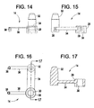
FIG. 14 is a side elevation view of one of the terminal assemblies of the battery ofFIG. 1 ; -
FIG. 15 is an end elevation view of the terminal assembly of the battery ofFIG. 1 ; -
FIG. 16 is a top plan view of one of the terminal assembly of the battery ofFIG. 1 ;
and -
FIG. 17 is a sectional view of the terminal assembly of the battery ofFIG. 1 , taken alongline 17--17 ofFIG. 16 . - Like reference characters designate identical or corresponding components and units throughout the several views.
- Referring to
FIGS. 1 through 13 , the present disclosure provides abattery 10 including abattery post cover 12 havingterminal assemblies 14 for measuring electrical energy passing to and fromposts 16 of thebattery 10. Thebattery 10 is generally similar to typical lead-acid 12 Volt and 36 Volt batteries for use in powering vehicles, such as trucks, automobiles and motorcycles. It should be understood, however, that the present disclosure can be used with many different types of batteries other than lead-acid batteries, such as nickel metal hydride, lithium ion, and lithium polymer batteries. - As shown in
FIGS. 1,2 and7 through 13 , thebattery 10 includes aplastic casing 18 having anopen top 20 andcell dividers 22 separatingfuel cells 24. Eachfuel cell 24 contains positive and negative lead plates separated by non-conductive sheets and immersed in an acid electrolyte. Thebattery 10 also includes positive lead straps 26 connecting the positive plates and negative lead straps 26 connecting the negative plates. The positivelead post 16 is connected to the positive plates, while the negativelead post 16 is connected to the negative plates. Bothposts 16 extend out of theopen top 20 of thecase 18. - Referring to
FIGS. 1, 2 and14 through 17 , eachterminal assembly 14 includes an electricallyconductive collar 28 having aninner surface 30 for contacting thebattery post 16, and an electricallyconductive terminal 32 for receiving a connector (not shown) of a load, such as a cable clamp of a vehicle. Eachassembly 14 also includes an electricallyconductive shunt resistor 34 having a known resistance "R" extending between outer surfaces of thecollar 28 and the terminal 32. Current flow "I" from thebattery post 16 travels through theresistor 34 from thecollar 28 to the terminal 32 and current flow to thebattery post 16 travels through theresistor 34 from the terminal 32 to thecollar 28. Leads 36 extend from the outer surfaces of thecollar 28 and the terminal 32 for measuring a voltage drop "v" across theresistor 34. The leads 36 can include threadedconnectors 38, as shown. - The known resistance "R" of the
resistor 34 is calculated by multiplying the ratio of length of theresistor 34 divided by the cross sectional area of theresistor 34 by the resistivity of the material that theresistor 34 is made of. The material from which theterminal assembly 32 is made can be lead or a non-lead material, as long as the resistance "R" of theresistor 34 is precisely known for purposes of determining current flow "I". - Other conductive materials, such as copper, brass and bronze can alternatively be used, the material selection is based on the galvanic compatibility of the
resistor 34 material with the electrochemical system being employed. Also, theresistor 34 can be made from commercially available alloy materials having a very low temperature coefficient of resistivity, such as Manganin, to reduce the effects of temperature variation when determining current flow "I". Theresistor 34 can be formed of powdered metal, stamped, machined, cast, or forged. Theresistor 34 can also be insert cast with thecollar 28 and the terminal 32 if theresistor 34 is made of different materials than thecollar 28 and the terminal 32. In addition, thecollar 28 and the terminal 32 can be plated or dipped in silver, gold, platinum or their alloys to provide a non-corrosive surface, and further dipped or coated with tin to provide better attachment between the lead battery post and platedcollar 28. Theinner surface 30 of thecollar 28 is secured to thebattery post 16, as shown best inFIG. 13 , withlead solder 40 for example, to provide an electrical connection and to prevent electrolyte from leaking from thebattery 10. - The
resistor 34 is configured for use with a typical lead-acid vehicle battery 10 to measure currents between 0.5 amperes and 1000 amperes, with theresistor 34 being provided with a known resistance "R" of between about 50 microOhm and about 200 microOhm. Preferably, theresistor 34 is provided with a known resistance "R" of about 150 microOhm. The resistance value, of course, is determined based on a trade-off between current measurement accuracy and power dissipation at high current. - Referring to
FIGS. 1 through 6 , thebattery post cover 12 is made of a suitably rigid and durable plastic and includes afirst surface 42 having twopost ports 44, asecond surface 46 having twoterminal ports 48, and a substantially closedchamber 50 receiving acircuit board 52. Theterminal assemblies 14 are received within thecover 12 with theterminals 32 extending through theterminal ports 48, thecollars 28 positioned within thepost ports 44, and theleads 36 extending into theclosed chamber 50 of the cover. The threadedconnectors 38 of theleads 36 are electrically connected to lands of thecircuit board 52 withscrews 54, for example. - A two-
piece cover 12 is employed for ease of manufacture, with theterminal assemblies 14 insert molded to aninner portion 56 of the cover. Theinner portion 56 is secured to thebattery case 18, through ultrasonic welding for example, such that theopen top 20 of thecase 18 is sealed shut in a fluid-tight manner. Then anouter portion 58 of thecover 12 is secured to theinner portion 56 to secure and protect thecircuit board 52 within the cover. Thecover 12 can alternatively be formed as a single piece with theterminal assemblies 14 and thecircuit board 52 insert molded therein, or can be constructed from more than two pieces. - Although not described in detail herein, the
circuit board 52 has arranged and mounted thereon an electrical circuit including components such as a volt meter connected to theleads 36 of at least one of theterminal assemblies 14 for measuring the voltage drops "v" across theresistors 34. The electrical circuit also includes a memory storing the known resistance "R" of theresistors 34 and a processor programmed to receive the measured voltage drop "v" from the volt meter, retrieve the known resistance "R" from the memory, and calculate current flow "I" through theresistors 34 based on the measured voltage drop "v" and the known resistance "R". Other components of the circuit can include an analog-to-digital converter for converting an analog signal from the volt meter to a digital signal for the computer, an indicator such as an LED, and an input/output circuit for connecting the computer to a remote device such as a display screen mounted on the dashboard of a vehicle, or a personal computer with a keyboard, mouse and other user input devices. An example of a circuit for use on thecircuit board 52 is thePS3180 SmartShunt Battery 10 Monitor available from the assignee of the present disclosure, PawerSmart, Inc. of Needham, MA (www. powersmart. com). - If the
resistors 34 of theterminal assemblies 14 are made of a material having a relatively high temperature coefficient of resistivity, thecircuit board 52 can be provided with a thermometer, such as a solid state silicon thermistor, for measuring an actual temperature of theresistors 34. In such acase 18, the memory of the circuit also stores a temperature coefficient of resistivity for theresistor 34, and the processor is further programmed to receive the actual temperature from the thermometer, retrieve the temperature coefficient of resistivity from the memory, calculate an actual resistance of theresistor 34 based on the known resistance "R" (at a ideal temperature), the temperature coefficient of resistivity, and the actual temperature. The processor is also programmed to calculate actual current flow through theresistor 34 based on the measured voltage drop and the actual resistance. - The
circuit board 52 is preferably also provided with a clock and the processor is programmed to calculate the total charge of thebattery 10 based on the current flow "I" and the charge time (when current is provided to the battery 10) or the drain time (when current is taken from the battery 10). - The present disclosure, accordingly, provides a new and
improved battery 10 includingterminal assemblies 14 for monitoring the terminal voltage, the flow of current into and out of thebattery 10 and means to mechanically and electrically integrate electronic circuitry for the measure and analysis of battery voltage and current. As preferred, thebattery 10 is simple in design, relatively inexpensive and capable of manufacture in high volumes. Certain modifications and improvements will occur to those skilled in the art upon a reading of the foregoing description. By way of example, the outer surfaces of theterminals 32 can include channels for dissipating heat. In addition, thebattery post cover 12 disclosed herein can be modified so as able to be retrofit onto the covers of existing batteries. Thebattery post cover 12 can also be modified so as to include a singleterminal assembly 14 for connection to either a positive ornegative post 16 of abattery 10. Furthermore, thecircuit board 52 of thebattery post cover 12 can be provided with additional features and abilities. - It should be understood that all such modifications and improvements are properly within the scope of the following claims. In addition, all embodiments shown and described in the present disclosure are within the scope of at least one of the claims.
- No embodiments or portions thereof are meant to be dedicated to the public prior to the expiration of any patent obtained for this disclosure.
Claims (15)
- A terminal assembly for a battery, comprising:- an electrically conductive collar (28) having an inner surface (30) for contacting a battery post (16);- an electrically conductive terminal (32);- a metallic alloy (34) extending between said electrically conductive collar (28) and said electrically conductive terminal (32) such that an integrated electrically conductive structure (14) is formed, wherein said alloy forms a shunt resistor (34) between said collar (28) and said terminal (32).
- The terminal assembly according to claim 1, further comprising first and second leads (36) extending from the outer surfaces of the collar (28) and the terminal (32), respectively.
- The terminal assembly according to claim 1 or 2, wherein said metallic alloy (34) comprises manganese, nickel or copper.
- The terminal assembly according to one of the preceding claims, wherein said terminal assembly comprises copper, brass or bronze.
- The terminal assembly according to one of the preceding claims, wherein said alloy has a very low temperature coefficient of resistivity.
- The terminal assembly according to one of the preceding claims, wherein the shunt resistor is formed of powdered metal, stamped, machined, cast, or forged.
- The terminal assembly according to one of the preceding claims, wherein the shunt resistor is insert cast with the collar (28) and the terminal (32).
- The terminal assembly according to one of the preceding claims, wherein the collar (28) and/or terminal (32) is plated.
- The terminal assembly according to one of the preceding claims, wherein the collar (28) and the terminal (32) have a non corrosive surface.
- The terminal assembly according to claim 9, wherein the collar (28) and/or the terminal (32) is dipped in silver, gold, platinum or one of their alloys.
- The terminal assembly according to claim 10, wherein the collar (28) and/or terminal (32) is further dipped or coated with tin.
- The terminal assembly according to one of the preceding claims, wherein the inner surface (30) of the collar (28) is secured to the battery post (16) and the terminal (32) is operable to receive a cable clamp.
- The terminal assembly according to claim 12, wherein the inner surface (30) is secured to the collar (28) by lead solder (40).
- The terminal assembly according to one of the preceding claims 2-13, further comprising measuring means connected to said first and second leads (36), a processor coupled with said measuring means and a memory coupled with said processor.
- The terminal assembly according to claim 14, further comprising a thermometer coupled with said processor.
Applications Claiming Priority (4)
| Application Number | Priority Date | Filing Date | Title |
|---|---|---|---|
| US28213301P | 2001-04-06 | 2001-04-06 | |
| US10/010,693 US6628102B2 (en) | 2001-04-06 | 2001-12-05 | Current measuring terminal assembly for a battery |
| EP02759845.7A EP1374364B1 (en) | 2001-04-06 | 2002-01-23 | Terminal assembly for battery |
| PCT/US2002/001755 WO2002082617A1 (en) | 2001-04-06 | 2002-01-23 | Terminal assembly for battery |
Related Parent Applications (3)
| Application Number | Title | Priority Date | Filing Date |
|---|---|---|---|
| EP02759845.7A Division-Into EP1374364B1 (en) | 2001-04-06 | 2002-01-23 | Terminal assembly for battery |
| EP02759845.7A Division EP1374364B1 (en) | 2001-04-06 | 2002-01-23 | Terminal assembly for battery |
| EP02759845.7 Division | 2002-01-23 |
Publications (2)
| Publication Number | Publication Date |
|---|---|
| EP2256900A1 true EP2256900A1 (en) | 2010-12-01 |
| EP2256900B1 EP2256900B1 (en) | 2018-10-03 |
Family
ID=26681486
Family Applications (2)
| Application Number | Title | Priority Date | Filing Date |
|---|---|---|---|
| EP02759845.7A Expired - Lifetime EP1374364B1 (en) | 2001-04-06 | 2002-01-23 | Terminal assembly for battery |
| EP10177750.6A Expired - Lifetime EP2256900B1 (en) | 2001-04-06 | 2002-01-23 | Terminal Assembly for a Battery |
Family Applications Before (1)
| Application Number | Title | Priority Date | Filing Date |
|---|---|---|---|
| EP02759845.7A Expired - Lifetime EP1374364B1 (en) | 2001-04-06 | 2002-01-23 | Terminal assembly for battery |
Country Status (3)
| Country | Link |
|---|---|
| US (2) | US6628102B2 (en) |
| EP (2) | EP1374364B1 (en) |
| WO (1) | WO2002082617A1 (en) |
Cited By (1)
| Publication number | Priority date | Publication date | Assignee | Title |
|---|---|---|---|---|
| EP2782162A1 (en) * | 2013-03-19 | 2014-09-24 | GS Yuasa International Ltd. | Electric storage apparatus |
Families Citing this family (60)
| Publication number | Priority date | Publication date | Assignee | Title |
|---|---|---|---|---|
| US6628102B2 (en) | 2001-04-06 | 2003-09-30 | Microchip Technology Inc. | Current measuring terminal assembly for a battery |
| US7205746B2 (en) * | 2001-04-06 | 2007-04-17 | Microchip Technology Inc. | Battery cover assembly having integrated battery condition monitoring |
| DE60202485T2 (en) * | 2001-08-07 | 2005-12-29 | Vehicle Enhancement Systems, Inc. | SYSTEM AND METHOD FOR MONITORING PERFORMANCE DATA RELATING TO AN ELECTRICAL COMPONENT |
| ITMI20032599A1 (en) * | 2003-12-24 | 2005-06-25 | Italiana Accumulatori Moto Carri Montecch Fab | MODULAR AND MODULAR POWER STATION |
| US20060105263A1 (en) * | 2004-11-16 | 2006-05-18 | Xerox Corporation | Toner composition |
| KR100696685B1 (en) * | 2005-05-16 | 2007-03-20 | 삼성에스디아이 주식회사 | Secondary battery module |
| US7524602B2 (en) * | 2005-06-20 | 2009-04-28 | Xerox Corporation | Low molecular weight latex and toner compositions comprising the same |
| US7662272B2 (en) | 2005-11-14 | 2010-02-16 | Xerox Corporation | Crystalline wax |
| US7686939B2 (en) * | 2005-11-14 | 2010-03-30 | Xerox Corporation | Crystalline wax |
| US7749670B2 (en) * | 2005-11-14 | 2010-07-06 | Xerox Corporation | Toner having crystalline wax |
| US7553596B2 (en) | 2005-11-14 | 2009-06-30 | Xerox Corporation | Toner having crystalline wax |
| US7910275B2 (en) * | 2005-11-14 | 2011-03-22 | Xerox Corporation | Toner having crystalline wax |
| US7385828B2 (en) * | 2006-01-27 | 2008-06-10 | Delphi Technologies, Inc. | Electronic shunt resistor assembly |
| US7688022B2 (en) | 2006-02-17 | 2010-03-30 | Lear Corporation | Energy management system for a vehicle |
| WO2007124767A1 (en) * | 2006-04-28 | 2007-11-08 | Daimler Ag | Fuel cell apparatus with a current sensor and current sensor for a fuel cell apparatus |
| US7381101B2 (en) * | 2006-08-25 | 2008-06-03 | Lear Corporation | Battery post connector |
| US7500888B2 (en) * | 2007-02-08 | 2009-03-10 | Lear Corporation | Battery post connector |
| US8278018B2 (en) * | 2007-03-14 | 2012-10-02 | Xerox Corporation | Process for producing dry ink colorants that will reduce metamerism |
| US8476864B2 (en) * | 2007-06-13 | 2013-07-02 | Lear Corporation | Battery monitoring system |
| US20090168290A1 (en) * | 2007-12-28 | 2009-07-02 | Patrick Dale Riedlinger | Battery clip wtih integrated microprocessor reset switch and method of operating |
| US8305034B2 (en) * | 2008-07-23 | 2012-11-06 | Lear Corporation | Battery monitoring system |
| DE102008054452A1 (en) | 2008-12-10 | 2010-06-17 | Robert Bosch Gmbh | Polklemmenanordnung |
| US8076048B2 (en) * | 2009-03-17 | 2011-12-13 | Xerox Corporation | Toner having polyester resin |
| US8124307B2 (en) | 2009-03-30 | 2012-02-28 | Xerox Corporation | Toner having polyester resin |
| US8431306B2 (en) | 2010-03-09 | 2013-04-30 | Xerox Corporation | Polyester resin containing toner |
| CA2820626C (en) | 2010-12-07 | 2018-01-09 | Allison Transmission, Inc. | Energy storage system for hybrid electric vehicle |
| DE102011102211A1 (en) * | 2011-05-21 | 2012-11-22 | Otto Diez Elektromaschinenbau | Device and method for monitoring operating data of a battery system |
| US9472797B2 (en) * | 2011-05-25 | 2016-10-18 | Samsung Sdi Co., Ltd. | Battery pack |
| DE102011076888A1 (en) * | 2011-06-01 | 2012-12-06 | Elringklinger Ag | Line system for connecting a plurality of voltage taps and / or temperature measuring points of an electrochemical device with a monitoring unit |
| JP5825904B2 (en) * | 2011-07-27 | 2015-12-02 | 矢崎総業株式会社 | Battery status notification unit, bus bar module, assembled battery, and battery status monitoring system |
| US9559509B2 (en) * | 2011-10-13 | 2017-01-31 | Keihin Corporation | Power supply control device |
| KR101658025B1 (en) * | 2011-11-02 | 2016-09-21 | 삼성에스디아이 주식회사 | Secondary battery |
| US8574803B2 (en) | 2011-12-23 | 2013-11-05 | Xerox Corporation | Toner compositions of biodegradable amorphous polyester resins |
| JP6136168B2 (en) * | 2012-09-28 | 2017-05-31 | 株式会社Gsユアサ | Assembled battery |
| EP2920829A4 (en) * | 2012-11-19 | 2016-12-07 | Aquion Energy Inc | Device and method for electrochemical device electrical interconnection |
| US20140152313A1 (en) * | 2012-12-03 | 2014-06-05 | Isabellenhuette Heusler Gmbh & Co. Kg | Battery sensor |
| DE102012222866A1 (en) * | 2012-12-12 | 2014-06-26 | Robert Bosch Gmbh | Cover for battery module of battery system for use in motor vehicle, has electrically conductive contact elements electrically conductively contacted with electric poles of battery cell during arrangement of covering body on module |
| KR102025947B1 (en) | 2012-12-27 | 2019-09-26 | 타이코에이엠피 주식회사 | Protection circuit module and battery module including the same |
| DE102013210128A1 (en) * | 2013-03-05 | 2014-09-11 | Continental Automotive Gmbh | Integrally formed current sensor device |
| DE102013203799A1 (en) * | 2013-03-06 | 2014-09-11 | Robert Bosch Gmbh | Battery cell housing with integrated electronics |
| JP5610012B2 (en) * | 2013-03-08 | 2014-10-22 | 株式会社豊田自動織機 | Battery module |
| US9440601B2 (en) | 2013-09-06 | 2016-09-13 | Johnson Controls Technology Company | System for providing voltage measurements of battery cells to a PCB within a battery module |
| US9328260B2 (en) | 2014-01-15 | 2016-05-03 | Xerox Corporation | Polyester processes |
| US9740124B2 (en) | 2015-05-25 | 2017-08-22 | Xerox Corporation | Toner compositions and processes |
| US9692245B2 (en) * | 2015-08-31 | 2017-06-27 | General Electric Company | Battery management system and power connector |
| GB2545699A (en) * | 2015-12-22 | 2017-06-28 | Poweroasis Ltd | Smart lead acid battery module |
| US10649355B2 (en) | 2016-07-20 | 2020-05-12 | Xerox Corporation | Method of making a polymer composite |
| US10315409B2 (en) | 2016-07-20 | 2019-06-11 | Xerox Corporation | Method of selective laser sintering |
| CN106526093B (en) * | 2016-12-27 | 2018-10-09 | 安徽理士电源技术有限公司 | A kind of lead-acid accumulator through-wall welding effect detection diaphragm capsule |
| TWI619290B (en) * | 2017-04-26 | 2018-03-21 | Zhang Nai Wen | Packaging method and structure of lead acid battery |
| JP2018189384A (en) * | 2017-04-28 | 2018-11-29 | 株式会社Gsユアサ | Current detection device, management device, and battery for starting engine |
| US10615395B2 (en) * | 2017-05-10 | 2020-04-07 | Apple Inc. | Battery cap with cut-out sections |
| CN109841909A (en) * | 2017-11-27 | 2019-06-04 | 广西明福科技有限公司 | One kind having durability and electricity early warning lead storage battery |
| EP3762983A1 (en) | 2018-03-05 | 2021-01-13 | CPS Technology Holdings LLC | Cap for battery terminal |
| CN117199730A (en) | 2018-03-05 | 2023-12-08 | Cps科技控股有限公司 | Battery terminal |
| DE102018217149A1 (en) * | 2018-10-08 | 2020-04-09 | Robert Bosch Gmbh | Electrochemical energy storage |
| US10667423B2 (en) * | 2018-10-26 | 2020-05-26 | Dell Products L.P. | Connector cooling and status indicator system |
| CN109391008A (en) * | 2018-11-20 | 2019-02-26 | 漳州高新区远见产业技术研究有限公司 | It is a kind of with the cellular li-ion battery for preventing from overcharging |
| CN210628444U (en) * | 2019-11-25 | 2020-05-26 | 宁德时代新能源科技股份有限公司 | Battery module, battery pack, and vehicle |
| CN116706408B (en) * | 2023-08-07 | 2023-11-07 | 风帆(扬州)有限责任公司 | Energy storage lithium battery convenient to overhaul and maintain |
Citations (4)
| Publication number | Priority date | Publication date | Assignee | Title |
|---|---|---|---|---|
| US5214407A (en) * | 1991-11-06 | 1993-05-25 | Hewlett-Packard Company | High performance current shunt |
| WO1999054744A1 (en) * | 1998-04-17 | 1999-10-28 | Menico Ag | Battery measuring terminal |
| US6001506A (en) * | 1997-07-30 | 1999-12-14 | Concorde Battery Corporation | Terminal post assembly for lead acid batteries |
| US6104967A (en) * | 1997-07-25 | 2000-08-15 | 3M Innovative Properties Company | Fault-tolerant battery system employing intra-battery network architecture |
Family Cites Families (73)
| Publication number | Priority date | Publication date | Assignee | Title |
|---|---|---|---|---|
| US3660759A (en) | 1970-03-19 | 1972-05-02 | Kal Equip Co | Meter connection adapter for automobile electrical system tester including diode and shorting switch therefor |
| US4045721A (en) * | 1974-12-30 | 1977-08-30 | Swain William H | Electro-chemical concentration transducer and its use to measure and control acid strength and storage battery charge |
| US4081693A (en) * | 1975-07-18 | 1978-03-28 | Stone Gordon R | Vehicular propulsion system |
| US4021718A (en) * | 1975-08-21 | 1977-05-03 | General Electric Company | Battery monitoring apparatus |
| US4193025A (en) * | 1977-12-23 | 1980-03-11 | Globe-Union, Inc. | Automatic battery analyzer |
| US4180770A (en) * | 1978-03-01 | 1979-12-25 | Anderson Power Products, Inc. | Method and apparatus for determining the capacity of lead acid storage batteries |
| US4349775A (en) * | 1981-01-02 | 1982-09-14 | Exxon Research & Engineering Co. | Temperature compensated voltage regulator for photovoltaic charging systems |
| US4396880A (en) * | 1981-06-05 | 1983-08-02 | Firing Circuits Inc. | Method and apparatus for charging a battery |
| US4460870A (en) * | 1981-07-23 | 1984-07-17 | Curtis Instruments, Inc. | Quiescent voltage sampling battery state of charge meter |
| US4470654A (en) * | 1982-04-20 | 1984-09-11 | Burndy Corporation | Electrical cable connector |
| US4709202A (en) * | 1982-06-07 | 1987-11-24 | Norand Corporation | Battery powered system |
| FR2528583B1 (en) * | 1982-06-11 | 1987-03-06 | Mitsubishi Electric Corp | CHARGE CIRCUIT DIAGNOSTIC DEVICE |
| US4558281A (en) * | 1982-06-12 | 1985-12-10 | Lucas Industries | Battery state of charge evaluator |
| US4564798A (en) * | 1982-10-06 | 1986-01-14 | Escutcheon Associates | Battery performance control |
| US4629964A (en) * | 1983-09-28 | 1986-12-16 | Ball Newton E | Battery power source |
| JPS61170678A (en) * | 1985-01-25 | 1986-08-01 | Nissan Motor Co Ltd | Battery state detector |
| DE3532044A1 (en) * | 1985-09-09 | 1987-03-19 | Vdo Schindling | POLE CLAMP |
| JPH01143984A (en) * | 1987-11-30 | 1989-06-06 | Aisin Aw Co Ltd | Device for monitoring battery state |
| GB8804011D0 (en) * | 1988-02-22 | 1988-03-23 | Tremblay A | Polarity indicator for car batteries |
| US5047961A (en) * | 1988-05-31 | 1991-09-10 | Simonsen Bent P | Automatic battery monitoring system |
| US5281919A (en) * | 1988-10-14 | 1994-01-25 | Alliedsignal Inc. | Automotive battery status monitor |
| US4968942A (en) * | 1988-10-14 | 1990-11-06 | Allied-Signal Inc. | Method for monitoring aircraft battery status |
| US4937528A (en) * | 1988-10-14 | 1990-06-26 | Allied-Signal Inc. | Method for monitoring automotive battery status |
| US4876513A (en) * | 1988-12-05 | 1989-10-24 | Globe-Union Inc. | Dynamic state-of-charge indicator for a battery and method thereof |
| US5160880A (en) * | 1989-05-10 | 1992-11-03 | Allied-Signal Inc. | Method and apparatus for charging and testing batteries |
| US5049803A (en) * | 1989-05-10 | 1991-09-17 | Allied-Signal Inc. | Method and apparatus for charging and testing batteries |
| US5132626A (en) * | 1989-05-31 | 1992-07-21 | Amoco Corporation | Electrolytic storage cell monitoring system |
| US5339018A (en) * | 1989-06-30 | 1994-08-16 | Analog Devices, Inc. | Integrated circuit monitor for storage battery voltage and temperature |
| US5432429A (en) * | 1990-10-23 | 1995-07-11 | Benchmarq Microelectronics, Inc. | System for charging/monitoring batteries for a microprocessor based system |
| US5191291A (en) * | 1991-04-30 | 1993-03-02 | George Taylor | Method and apparatus for determining the performance capabilities of secondary batteries |
| CA2043959A1 (en) * | 1991-06-05 | 1992-12-06 | Gerard Patrick Gibbons | Battery monitoring system |
| US5250904A (en) * | 1991-08-08 | 1993-10-05 | Advanced Power Technology Inc. | Device for predicting imminent failure of a stationary lead acid battery in a float mode |
| US5321627A (en) * | 1992-03-11 | 1994-06-14 | Globe-Union, Inc. | Battery monitor and method for providing operating parameters |
| US5321347A (en) * | 1992-04-09 | 1994-06-14 | Chien Chih Chien | Battery charger device and method |
| EP0593196A3 (en) * | 1992-10-13 | 1994-12-28 | Gnb Battery Tech Inc | Method for optimizing the charging of lead-acid batteries and an interactive charger. |
| US5656920A (en) * | 1992-10-13 | 1997-08-12 | Gnb Battery Technologies, Inc. | Method and apparatus for charging a lead-acid battery |
| FR2704982B1 (en) * | 1993-05-06 | 1995-06-09 | Alsthom Cge Alcatel | ELECTROCHEMICAL GENERATOR RECOGNITION AND MANAGEMENT SYSTEM. |
| DE4339568A1 (en) * | 1993-11-19 | 1995-05-24 | Bosch Gmbh Robert | Method for determining the state of charge of a battery, in particular a vehicle starter battery |
| KR0180390B1 (en) * | 1994-06-16 | 1999-05-15 | 전성원 | Battery charging control of electric vehicle and its method |
| US5617007A (en) * | 1994-08-17 | 1997-04-01 | International Business Machines Corporation | Battery charging method and apparatus using current control |
| JPH08136628A (en) | 1994-11-11 | 1996-05-31 | Fujitsu Ltd | Device for monitoring capacity of battery |
| US5631540A (en) * | 1994-11-23 | 1997-05-20 | Lucent Technologies Inc. | Method and apparatus for predicting the remaining capacity and reserve time of a battery on discharge |
| JPH08160113A (en) | 1994-12-02 | 1996-06-21 | Nippon Soken Inc | Battery state judgement device |
| US5572110A (en) * | 1994-12-15 | 1996-11-05 | Intel Corporation | Smart battery charger system |
| US5541489A (en) * | 1994-12-15 | 1996-07-30 | Intel Corporation | Smart battery power availability feature based on battery-specific characteristics |
| US5600230A (en) * | 1994-12-15 | 1997-02-04 | Intel Corporation | Smart battery providing programmable remaining capacity and run-time alarms based on battery-specific characteristics |
| US5565759A (en) * | 1994-12-15 | 1996-10-15 | Intel Corporation | Smart battery providing battery life and recharge time prediction |
| US5627453A (en) * | 1995-01-11 | 1997-05-06 | Dell Usa, L.P. | Smart battery odometer |
| US5710506A (en) * | 1995-02-07 | 1998-01-20 | Benchmarq Microelectronics, Inc. | Lead acid charger |
| US5670863A (en) * | 1995-02-07 | 1997-09-23 | Benchmarq Microelectronics, Inc. | Lead acid charger with ratioed time-out periods and current pulse mode of operation |
| US5659240A (en) * | 1995-02-16 | 1997-08-19 | General Electric Company | Intelligent battery charger for electric drive system batteries |
| US5550475A (en) * | 1995-04-11 | 1996-08-27 | Shafer; Timothy M. | Programmable battery charge indicator |
| FR2740554A1 (en) * | 1995-10-31 | 1997-04-30 | Philips Electronique Lab | SYSTEM FOR MONITORING THE DISCHARGE PHASE OF THE CHARGING-DISCHARGE CYCLES OF A RECHARGEABLE BATTERY, AND HOST DEVICE PROVIDED WITH AN INTELLIGENT BATTERY |
| FR2740555A1 (en) * | 1995-10-31 | 1997-04-30 | Philips Electronique Lab | SYSTEM FOR MONITORING THE CHARGING-DISCHARGE CYCLES OF A RECHARGEABLE BATTERY, AND HOST DEVICE PROVIDED WITH AN INTELLIGENT BATTERY |
| US5708348A (en) * | 1995-11-20 | 1998-01-13 | Warren Johnson | Method and apparatus for monitoring battery voltage |
| US5808445A (en) * | 1995-12-06 | 1998-09-15 | The University Of Virginia Patent Foundation | Method for monitoring remaining battery capacity |
| US5629680A (en) | 1995-12-11 | 1997-05-13 | Makhija; Surender K. | Vehicle current drain tester with memory saver |
| US5710503A (en) * | 1996-02-01 | 1998-01-20 | Aims Systems, Inc. | On-line battery monitoring system with defective cell detection capability |
| KR0181164B1 (en) * | 1996-07-06 | 1999-05-15 | 삼성전자주식회사 | Charging apparatus for variable kinds of batteries and its control method |
| US5739670A (en) * | 1996-10-31 | 1998-04-14 | General Motors Corporation | Method for diagnosing battery condition |
| US5734252A (en) * | 1996-12-20 | 1998-03-31 | Ericsson, Inc. | Method and apparatus for charging a battery of an electronic device using an intelligent external charger |
| US5903764A (en) * | 1997-05-02 | 1999-05-11 | Micro International, Ltd. | Smart battery selector offering power conversion internally within a portable device |
| US5994876A (en) * | 1997-10-09 | 1999-11-30 | Abbott Laboratories | Battery capacity measurement circuit |
| US5828201A (en) * | 1997-10-30 | 1998-10-27 | Lockheed Martin Corporation | Method for maintaining the charge capacity of traction battery modules of a hybrid electric vehicle |
| TW419592B (en) * | 1998-03-31 | 2001-01-21 | Hitachi Maxell | Current accumulating value detecting apparatus, current detecting apparatus and the battery set used |
| SE514551C2 (en) * | 1998-06-24 | 2001-03-12 | Intra Internat Ab | Battery indicating charge state |
| US5949219A (en) * | 1998-07-24 | 1999-09-07 | The United States Of America As Represented By The United States Department Of Energy | Optical state-of-charge monitor for batteries |
| JP3740323B2 (en) * | 1998-07-31 | 2006-02-01 | キヤノン株式会社 | Secondary battery charging method and apparatus |
| JP3723376B2 (en) * | 1999-03-29 | 2005-12-07 | 三洋電機株式会社 | Sealed square battery |
| DE19961311A1 (en) * | 1999-12-18 | 2001-07-26 | Bayerische Motoren Werke Ag | Battery sensor device, has attachment device, sensor combined into integrated unit; attachment device is connected to single pole and has conventional terminal |
| DE60139042D1 (en) * | 2000-04-04 | 2009-07-30 | Microchip Tech Inc | Current measuring device for a battery |
| JP2002257639A (en) * | 2001-02-20 | 2002-09-11 | Binyou Chin | Ic circuitry of electronic clinical thermometer |
| US6628102B2 (en) | 2001-04-06 | 2003-09-30 | Microchip Technology Inc. | Current measuring terminal assembly for a battery |
-
2001
- 2001-12-05 US US10/010,693 patent/US6628102B2/en not_active Expired - Lifetime
-
2002
- 2002-01-23 WO PCT/US2002/001755 patent/WO2002082617A1/en not_active Application Discontinuation
- 2002-01-23 EP EP02759845.7A patent/EP1374364B1/en not_active Expired - Lifetime
- 2002-01-23 EP EP10177750.6A patent/EP2256900B1/en not_active Expired - Lifetime
-
2003
- 2003-04-21 US US10/419,600 patent/US7012404B2/en not_active Expired - Lifetime
Patent Citations (4)
| Publication number | Priority date | Publication date | Assignee | Title |
|---|---|---|---|---|
| US5214407A (en) * | 1991-11-06 | 1993-05-25 | Hewlett-Packard Company | High performance current shunt |
| US6104967A (en) * | 1997-07-25 | 2000-08-15 | 3M Innovative Properties Company | Fault-tolerant battery system employing intra-battery network architecture |
| US6001506A (en) * | 1997-07-30 | 1999-12-14 | Concorde Battery Corporation | Terminal post assembly for lead acid batteries |
| WO1999054744A1 (en) * | 1998-04-17 | 1999-10-28 | Menico Ag | Battery measuring terminal |
Non-Patent Citations (1)
| Title |
|---|
| "PS3180 SmartShunt TM Battery Monitor", INTERNET CITATION, 23 October 2000 (2000-10-23), XP002960182 * |
Cited By (3)
| Publication number | Priority date | Publication date | Assignee | Title |
|---|---|---|---|---|
| EP2782162A1 (en) * | 2013-03-19 | 2014-09-24 | GS Yuasa International Ltd. | Electric storage apparatus |
| JP2014182945A (en) * | 2013-03-19 | 2014-09-29 | Gs Yuasa Corp | Power storage device |
| US9786960B2 (en) | 2013-03-19 | 2017-10-10 | Gs Yuasa International Ltd. | Electric storage apparatus |
Also Published As
| Publication number | Publication date |
|---|---|
| EP1374364B1 (en) | 2018-07-11 |
| US7012404B2 (en) | 2006-03-14 |
| EP1374364A4 (en) | 2008-05-14 |
| US20040012396A1 (en) | 2004-01-22 |
| EP1374364A1 (en) | 2004-01-02 |
| US20020180405A1 (en) | 2002-12-05 |
| WO2002082617A1 (en) | 2002-10-17 |
| US6628102B2 (en) | 2003-09-30 |
| EP2256900B1 (en) | 2018-10-03 |
Similar Documents
| Publication | Publication Date | Title |
|---|---|---|
| EP2256900B1 (en) | Terminal Assembly for a Battery | |
| US7205746B2 (en) | Battery cover assembly having integrated battery condition monitoring | |
| EP1247304B1 (en) | Shunt resistance device for monitoring battery state of charge | |
| EP1807710B1 (en) | Kelvin connector including temperature sensor | |
| US6507196B2 (en) | Battery having discharge state indication | |
| US6573723B2 (en) | Current measuring apparatus for battery | |
| WO2006049393A1 (en) | Member for measurement of cell voltage and temperature in battery pack | |
| US10613147B2 (en) | Current shunt for measuring battery current | |
| US5304433A (en) | Capacity indicator for lead-acid batteries | |
| KR102512068B1 (en) | Battery module with thermocouple unit | |
| CN109863624A (en) | Busbar for battery system and the battery system with the busbar | |
| US11639967B2 (en) | Sensor system for a battery module | |
| EP1876461B1 (en) | Current measuring apparatus for battery | |
| EP3823076A1 (en) | Sensor system for a battery module | |
| CN112436178A (en) | Lithium ion battery, third electrode testing method thereof, battery module and automobile | |
| JPH08203568A (en) | Secondary battery pack | |
| JPS63157079A (en) | Charging and discharging current detector for battery for internal combustion engine |
Legal Events
| Date | Code | Title | Description |
|---|---|---|---|
| PUAI | Public reference made under article 153(3) epc to a published international application that has entered the european phase |
Free format text: ORIGINAL CODE: 0009012 |
|
| 17P | Request for examination filed |
Effective date: 20100920 |
|
| AC | Divisional application: reference to earlier application |
Ref document number: 1374364 Country of ref document: EP Kind code of ref document: P |
|
| AK | Designated contracting states |
Kind code of ref document: A1 Designated state(s): AT BE CH CY DE DK ES FI FR GB GR IE IT LI LU MC NL PT SE TR |
|
| STAA | Information on the status of an ep patent application or granted ep patent |
Free format text: STATUS: EXAMINATION IS IN PROGRESS |
|
| 17Q | First examination report despatched |
Effective date: 20161109 |
|
| GRAP | Despatch of communication of intention to grant a patent |
Free format text: ORIGINAL CODE: EPIDOSNIGR1 |
|
| STAA | Information on the status of an ep patent application or granted ep patent |
Free format text: STATUS: GRANT OF PATENT IS INTENDED |
|
| INTG | Intention to grant announced |
Effective date: 20180502 |
|
| GRAS | Grant fee paid |
Free format text: ORIGINAL CODE: EPIDOSNIGR3 |
|
| GRAA | (expected) grant |
Free format text: ORIGINAL CODE: 0009210 |
|
| STAA | Information on the status of an ep patent application or granted ep patent |
Free format text: STATUS: THE PATENT HAS BEEN GRANTED |
|
| AC | Divisional application: reference to earlier application |
Ref document number: 1374364 Country of ref document: EP Kind code of ref document: P |
|
| AK | Designated contracting states |
Kind code of ref document: B1 Designated state(s): AT BE CH CY DE DK ES FI FR GB GR IE IT LI LU MC NL PT SE TR |
|
| REG | Reference to a national code |
Ref country code: GB Ref legal event code: FG4D |
|
| REG | Reference to a national code |
Ref country code: CH Ref legal event code: EP Ref country code: AT Ref legal event code: REF Ref document number: 1049671 Country of ref document: AT Kind code of ref document: T Effective date: 20181015 |
|
| REG | Reference to a national code |
Ref country code: DE Ref legal event code: R096 Ref document number: 60249634 Country of ref document: DE |
|
| REG | Reference to a national code |
Ref country code: IE Ref legal event code: FG4D |
|
| REG | Reference to a national code |
Ref country code: NL Ref legal event code: MP Effective date: 20181003 |
|
| REG | Reference to a national code |
Ref country code: AT Ref legal event code: MK05 Ref document number: 1049671 Country of ref document: AT Kind code of ref document: T Effective date: 20181003 |
|
| PG25 | Lapsed in a contracting state [announced via postgrant information from national office to epo] |
Ref country code: NL Free format text: LAPSE BECAUSE OF FAILURE TO SUBMIT A TRANSLATION OF THE DESCRIPTION OR TO PAY THE FEE WITHIN THE PRESCRIBED TIME-LIMIT Effective date: 20181003 |
|
| PG25 | Lapsed in a contracting state [announced via postgrant information from national office to epo] |
Ref country code: ES Free format text: LAPSE BECAUSE OF FAILURE TO SUBMIT A TRANSLATION OF THE DESCRIPTION OR TO PAY THE FEE WITHIN THE PRESCRIBED TIME-LIMIT Effective date: 20181003 Ref country code: AT Free format text: LAPSE BECAUSE OF FAILURE TO SUBMIT A TRANSLATION OF THE DESCRIPTION OR TO PAY THE FEE WITHIN THE PRESCRIBED TIME-LIMIT Effective date: 20181003 Ref country code: FI Free format text: LAPSE BECAUSE OF FAILURE TO SUBMIT A TRANSLATION OF THE DESCRIPTION OR TO PAY THE FEE WITHIN THE PRESCRIBED TIME-LIMIT Effective date: 20181003 |
|
| PG25 | Lapsed in a contracting state [announced via postgrant information from national office to epo] |
Ref country code: SE Free format text: LAPSE BECAUSE OF FAILURE TO SUBMIT A TRANSLATION OF THE DESCRIPTION OR TO PAY THE FEE WITHIN THE PRESCRIBED TIME-LIMIT Effective date: 20181003 Ref country code: PT Free format text: LAPSE BECAUSE OF FAILURE TO SUBMIT A TRANSLATION OF THE DESCRIPTION OR TO PAY THE FEE WITHIN THE PRESCRIBED TIME-LIMIT Effective date: 20190203 Ref country code: GR Free format text: LAPSE BECAUSE OF FAILURE TO SUBMIT A TRANSLATION OF THE DESCRIPTION OR TO PAY THE FEE WITHIN THE PRESCRIBED TIME-LIMIT Effective date: 20190104 |
|
| REG | Reference to a national code |
Ref country code: DE Ref legal event code: R097 Ref document number: 60249634 Country of ref document: DE |
|
| PG25 | Lapsed in a contracting state [announced via postgrant information from national office to epo] |
Ref country code: IT Free format text: LAPSE BECAUSE OF FAILURE TO SUBMIT A TRANSLATION OF THE DESCRIPTION OR TO PAY THE FEE WITHIN THE PRESCRIBED TIME-LIMIT Effective date: 20181003 Ref country code: DK Free format text: LAPSE BECAUSE OF FAILURE TO SUBMIT A TRANSLATION OF THE DESCRIPTION OR TO PAY THE FEE WITHIN THE PRESCRIBED TIME-LIMIT Effective date: 20181003 |
|
| PLBE | No opposition filed within time limit |
Free format text: ORIGINAL CODE: 0009261 |
|
| STAA | Information on the status of an ep patent application or granted ep patent |
Free format text: STATUS: NO OPPOSITION FILED WITHIN TIME LIMIT |
|
| PG25 | Lapsed in a contracting state [announced via postgrant information from national office to epo] |
Ref country code: MC Free format text: LAPSE BECAUSE OF FAILURE TO SUBMIT A TRANSLATION OF THE DESCRIPTION OR TO PAY THE FEE WITHIN THE PRESCRIBED TIME-LIMIT Effective date: 20181003 |
|
| REG | Reference to a national code |
Ref country code: CH Ref legal event code: PL |
|
| 26N | No opposition filed |
Effective date: 20190704 |
|
| GBPC | Gb: european patent ceased through non-payment of renewal fee |
Effective date: 20190123 |
|
| PG25 | Lapsed in a contracting state [announced via postgrant information from national office to epo] |
Ref country code: LU Free format text: LAPSE BECAUSE OF NON-PAYMENT OF DUE FEES Effective date: 20190123 |
|
| REG | Reference to a national code |
Ref country code: BE Ref legal event code: MM Effective date: 20190131 |
|
| REG | Reference to a national code |
Ref country code: IE Ref legal event code: MM4A |
|
| PG25 | Lapsed in a contracting state [announced via postgrant information from national office to epo] |
Ref country code: BE Free format text: LAPSE BECAUSE OF NON-PAYMENT OF DUE FEES Effective date: 20190131 |
|
| PG25 | Lapsed in a contracting state [announced via postgrant information from national office to epo] |
Ref country code: LI Free format text: LAPSE BECAUSE OF NON-PAYMENT OF DUE FEES Effective date: 20190131 Ref country code: GB Free format text: LAPSE BECAUSE OF NON-PAYMENT OF DUE FEES Effective date: 20190123 Ref country code: CH Free format text: LAPSE BECAUSE OF NON-PAYMENT OF DUE FEES Effective date: 20190131 |
|
| PG25 | Lapsed in a contracting state [announced via postgrant information from national office to epo] |
Ref country code: IE Free format text: LAPSE BECAUSE OF NON-PAYMENT OF DUE FEES Effective date: 20190123 |
|
| PG25 | Lapsed in a contracting state [announced via postgrant information from national office to epo] |
Ref country code: TR Free format text: LAPSE BECAUSE OF FAILURE TO SUBMIT A TRANSLATION OF THE DESCRIPTION OR TO PAY THE FEE WITHIN THE PRESCRIBED TIME-LIMIT Effective date: 20181003 |
|
| PGFP | Annual fee paid to national office [announced via postgrant information from national office to epo] |
Ref country code: FR Payment date: 20201217 Year of fee payment: 20 |
|
| PG25 | Lapsed in a contracting state [announced via postgrant information from national office to epo] |
Ref country code: CY Free format text: LAPSE BECAUSE OF FAILURE TO SUBMIT A TRANSLATION OF THE DESCRIPTION OR TO PAY THE FEE WITHIN THE PRESCRIBED TIME-LIMIT Effective date: 20181003 |
|
| PGFP | Annual fee paid to national office [announced via postgrant information from national office to epo] |
Ref country code: DE Payment date: 20201217 Year of fee payment: 20 |
|
| REG | Reference to a national code |
Ref country code: DE Ref legal event code: R071 Ref document number: 60249634 Country of ref document: DE |