EP2253450A1 - Extrusion coating device with adjustable die lips - Google Patents
Extrusion coating device with adjustable die lips Download PDFInfo
- Publication number
- EP2253450A1 EP2253450A1 EP20100161645 EP10161645A EP2253450A1 EP 2253450 A1 EP2253450 A1 EP 2253450A1 EP 20100161645 EP20100161645 EP 20100161645 EP 10161645 A EP10161645 A EP 10161645A EP 2253450 A1 EP2253450 A1 EP 2253450A1
- Authority
- EP
- European Patent Office
- Prior art keywords
- nozzle
- extrusion device
- mouthpieces
- carrier
- feeder
- Prior art date
- Legal status (The legal status is an assumption and is not a legal conclusion. Google has not performed a legal analysis and makes no representation as to the accuracy of the status listed.)
- Withdrawn
Links
Images


Classifications
-
- B—PERFORMING OPERATIONS; TRANSPORTING
- B29—WORKING OF PLASTICS; WORKING OF SUBSTANCES IN A PLASTIC STATE IN GENERAL
- B29C—SHAPING OR JOINING OF PLASTICS; SHAPING OF MATERIAL IN A PLASTIC STATE, NOT OTHERWISE PROVIDED FOR; AFTER-TREATMENT OF THE SHAPED PRODUCTS, e.g. REPAIRING
- B29C48/00—Extrusion moulding, i.e. expressing the moulding material through a die or nozzle which imparts the desired form; Apparatus therefor
- B29C48/25—Component parts, details or accessories; Auxiliary operations
- B29C48/30—Extrusion nozzles or dies
- B29C48/32—Extrusion nozzles or dies with annular openings, e.g. for forming tubular articles
- B29C48/34—Cross-head annular extrusion nozzles, i.e. for simultaneously receiving moulding material and the preform to be coated
-
- B—PERFORMING OPERATIONS; TRANSPORTING
- B29—WORKING OF PLASTICS; WORKING OF SUBSTANCES IN A PLASTIC STATE IN GENERAL
- B29C—SHAPING OR JOINING OF PLASTICS; SHAPING OF MATERIAL IN A PLASTIC STATE, NOT OTHERWISE PROVIDED FOR; AFTER-TREATMENT OF THE SHAPED PRODUCTS, e.g. REPAIRING
- B29C48/00—Extrusion moulding, i.e. expressing the moulding material through a die or nozzle which imparts the desired form; Apparatus therefor
- B29C48/15—Extrusion moulding, i.e. expressing the moulding material through a die or nozzle which imparts the desired form; Apparatus therefor incorporating preformed parts or layers, e.g. extrusion moulding around inserts
- B29C48/156—Coating two or more articles simultaneously
-
- B—PERFORMING OPERATIONS; TRANSPORTING
- B29—WORKING OF PLASTICS; WORKING OF SUBSTANCES IN A PLASTIC STATE IN GENERAL
- B29C—SHAPING OR JOINING OF PLASTICS; SHAPING OF MATERIAL IN A PLASTIC STATE, NOT OTHERWISE PROVIDED FOR; AFTER-TREATMENT OF THE SHAPED PRODUCTS, e.g. REPAIRING
- B29C48/00—Extrusion moulding, i.e. expressing the moulding material through a die or nozzle which imparts the desired form; Apparatus therefor
- B29C48/25—Component parts, details or accessories; Auxiliary operations
- B29C48/256—Exchangeable extruder parts
- B29C48/2566—Die parts
-
- B—PERFORMING OPERATIONS; TRANSPORTING
- B29—WORKING OF PLASTICS; WORKING OF SUBSTANCES IN A PLASTIC STATE IN GENERAL
- B29C—SHAPING OR JOINING OF PLASTICS; SHAPING OF MATERIAL IN A PLASTIC STATE, NOT OTHERWISE PROVIDED FOR; AFTER-TREATMENT OF THE SHAPED PRODUCTS, e.g. REPAIRING
- B29C48/00—Extrusion moulding, i.e. expressing the moulding material through a die or nozzle which imparts the desired form; Apparatus therefor
- B29C48/03—Extrusion moulding, i.e. expressing the moulding material through a die or nozzle which imparts the desired form; Apparatus therefor characterised by the shape of the extruded material at extrusion
- B29C48/05—Filamentary, e.g. strands
-
- B—PERFORMING OPERATIONS; TRANSPORTING
- B29—WORKING OF PLASTICS; WORKING OF SUBSTANCES IN A PLASTIC STATE IN GENERAL
- B29C—SHAPING OR JOINING OF PLASTICS; SHAPING OF MATERIAL IN A PLASTIC STATE, NOT OTHERWISE PROVIDED FOR; AFTER-TREATMENT OF THE SHAPED PRODUCTS, e.g. REPAIRING
- B29C48/00—Extrusion moulding, i.e. expressing the moulding material through a die or nozzle which imparts the desired form; Apparatus therefor
- B29C48/03—Extrusion moulding, i.e. expressing the moulding material through a die or nozzle which imparts the desired form; Apparatus therefor characterised by the shape of the extruded material at extrusion
- B29C48/07—Flat, e.g. panels
- B29C48/08—Flat, e.g. panels flexible, e.g. films
-
- B—PERFORMING OPERATIONS; TRANSPORTING
- B29—WORKING OF PLASTICS; WORKING OF SUBSTANCES IN A PLASTIC STATE IN GENERAL
- B29C—SHAPING OR JOINING OF PLASTICS; SHAPING OF MATERIAL IN A PLASTIC STATE, NOT OTHERWISE PROVIDED FOR; AFTER-TREATMENT OF THE SHAPED PRODUCTS, e.g. REPAIRING
- B29C48/00—Extrusion moulding, i.e. expressing the moulding material through a die or nozzle which imparts the desired form; Apparatus therefor
- B29C48/15—Extrusion moulding, i.e. expressing the moulding material through a die or nozzle which imparts the desired form; Apparatus therefor incorporating preformed parts or layers, e.g. extrusion moulding around inserts
- B29C48/154—Coating solid articles, i.e. non-hollow articles
-
- B—PERFORMING OPERATIONS; TRANSPORTING
- B29—WORKING OF PLASTICS; WORKING OF SUBSTANCES IN A PLASTIC STATE IN GENERAL
- B29C—SHAPING OR JOINING OF PLASTICS; SHAPING OF MATERIAL IN A PLASTIC STATE, NOT OTHERWISE PROVIDED FOR; AFTER-TREATMENT OF THE SHAPED PRODUCTS, e.g. REPAIRING
- B29C48/00—Extrusion moulding, i.e. expressing the moulding material through a die or nozzle which imparts the desired form; Apparatus therefor
- B29C48/25—Component parts, details or accessories; Auxiliary operations
- B29C48/30—Extrusion nozzles or dies
- B29C48/305—Extrusion nozzles or dies having a wide opening, e.g. for forming sheets
-
- B—PERFORMING OPERATIONS; TRANSPORTING
- B29—WORKING OF PLASTICS; WORKING OF SUBSTANCES IN A PLASTIC STATE IN GENERAL
- B29C—SHAPING OR JOINING OF PLASTICS; SHAPING OF MATERIAL IN A PLASTIC STATE, NOT OTHERWISE PROVIDED FOR; AFTER-TREATMENT OF THE SHAPED PRODUCTS, e.g. REPAIRING
- B29C48/00—Extrusion moulding, i.e. expressing the moulding material through a die or nozzle which imparts the desired form; Apparatus therefor
- B29C48/25—Component parts, details or accessories; Auxiliary operations
- B29C48/30—Extrusion nozzles or dies
- B29C48/32—Extrusion nozzles or dies with annular openings, e.g. for forming tubular articles
- B29C48/335—Multiple annular extrusion nozzles in coaxial arrangement, e.g. for making multi-layered tubular articles
-
- B—PERFORMING OPERATIONS; TRANSPORTING
- B29—WORKING OF PLASTICS; WORKING OF SUBSTANCES IN A PLASTIC STATE IN GENERAL
- B29C—SHAPING OR JOINING OF PLASTICS; SHAPING OF MATERIAL IN A PLASTIC STATE, NOT OTHERWISE PROVIDED FOR; AFTER-TREATMENT OF THE SHAPED PRODUCTS, e.g. REPAIRING
- B29C48/00—Extrusion moulding, i.e. expressing the moulding material through a die or nozzle which imparts the desired form; Apparatus therefor
- B29C48/25—Component parts, details or accessories; Auxiliary operations
- B29C48/30—Extrusion nozzles or dies
- B29C48/345—Extrusion nozzles comprising two or more adjacently arranged ports, for simultaneously extruding multiple strands, e.g. for pelletising
Definitions
- the invention relates to an extrusion device according to the preamble of claim 1.
- Such an extrusion device are wrapped with the threads of rubber compound and extruded together with this, has long been known, for example from US 2,760,230 or the GB 950 741 .
- wires or filaments are fed from a yarn guide to a nozzle, and between the yarn guide and the nozzle rubber material gets into the region of the filaments, wherein the filaments are enveloped.
- Such solutions have been and are used in a variety of configurations.
- the anchoring of the threads in the extrusion material is sufficient to achieve the desired effects.
- very thin threads can be poorly guided through the extrusion die and are in some cases also unsuitable, for example, if the threads a certain stiffness of the finished product to be achieved.
- the invention is based on the object to provide an extrusion device according to the preamble of claim 1, which is easier to handle even when thread breakage, so that there is the improved possibility to make a reassembly of a reinforcing member feeder at a possible yarn breakage.
- the possibility of accessing the reinforcing member feeder is made possible by the separation of the nozzle mouthpieces and, for example, it is extremely easy to replace torn filaments.
- it is surprisingly possible to work with extremely high pressure for the extrusion head which offers particular advantages with regard to the adhesion of the rubber compound to the surface of the filaments or reinforcement.
- a pressure of, for example, 400 bar in the feed area for the extrusion compound that is to say the area between reinforcing medium feeder and nozzle.
- Such pressure allows the micro-roughness of the surface of the filaments to be exploited and parts of the rubber compound to penetrate there. The surface effects thus produced substantially increase the adhesion, so that a large contact surface of the reinforcement can be utilized.
- the extrusion device according to the invention makes it possible with simple means to make the relative position of the reinforcing member feed to the nozzle adjustable. As a result, the remaining free space can be adapted in a wide range of requirements, for example, so the nature and condition of the reinforcement.
- the strength member feeder is then held in position by the pressure of the nozzle mouthpieces so that a manual adjustment device for the position of the strength member feeder is not loaded by the extrusion pressure.
- the strength carrier feeder is preferably flowed laterally from the exit of the extruder screw. As a result, the reinforcements are laterally exposed to rubber or another extrudable mass.
- the different flow length can be compensated, so that despite a pressure drop, a uniform Ausgeschgeschwintechnik can be realized with several products produced in parallel.
- cords are used as the strength carrier. If a cord breaks or breaks during production, the cords can be changed quickly by the easily releasable strength carrier according to the invention.
- Another advantage of the extrusion device according to the invention lies in the easy changeability of the nozzle inserts. Due to the division and relative movability of the nozzle mouthpieces to each other, the nozzle insert can be changed quickly in a conventional manner and thus adapted to the desired shape of the product to be extruded.
- nozzles and correspondingly associated nozzle mouthpieces side by side.
- the upper nozzle orifices may then preferably each be connected to each other as well as the lower nozzle orifices, wherein they may be realized in an upper nozzle carrier.
- the nozzle carriers can then be movable relative to one another, wherein the direction of travel is preferably vertical, so that all the upper nozzle orifices are separable from all lower nozzle orifices.
- the nozzle mouthpieces are each configured substantially semicircular in order to receive a nozzle insert.
- the nozzle insert is then interchangeable and has the respective nozzle slot formed in a suitable form on.
- the drive device according to the invention holds the nozzle mouthpieces according to the invention firmly together when extruded.
- a strong electromagnet may be provided, which is switched on during the extrusion and for the process, in particular for releasing the nozzle mouthpieces from each other off, or a bolt / nut combination.
- the drive device may be formed in any suitable manner.
- extrusion device 10 has a nozzle 12, which is provided in the illustrated embodiment with two nozzle orifices 14 and 16. These nozzle mouthpieces 14 and 16 are formed on an upper nozzle carrier 18 and a lower nozzle carrier 20 and enclose substantially in common a nozzle insert 22, which in turn has a nozzle slot 24.
- the nozzle carrier 18 and 20 - and thus also the nozzle mouthpieces 14 and 16 - are movable against each other.
- a drive device 26 is provided which acts vertically, and over which the upper nozzle carrier 18 is separable from the lower nozzle carrier 20 by being moved upwards.
- the nozzle carrier 18 and 20 are otherwise flat on each other.
- screw bolts 28, 30 are additionally provided with corresponding nuts 32 and 34, via which a fixation of the nozzle carriers 18 and 20 to each other is realized. It is understood that instead of this any other fixing means can be provided, and that it is also possible to ensure the closing state of the nozzle 12 in any other way.
- a smooth and straight dividing plane 40 is provided between the nozzle carriers 18 and 20, and the threaded bolts 28 and 30 pass through the upper nozzle carrier 18.
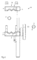
- Fig. 2 it can be seen how the nozzle carriers 18 and 20 can be moved apart. As can be seen there, the nozzle mouthpieces 14 and 16 are thereby separated from each other.
- the nozzle 12 is adjacent to a further nozzle 50, which also has two opposing nozzle orifices 52 and 54, which correspond in their configuration to the nozzle mouthpieces 14 and 16.
- the upper nozzle orifice 52 is formed together with the upper nozzle orifice 14 on the upper nozzle carrier 18, and the lower nozzle orifice 54 together with the lower nozzle orifice 16 on the lower nozzle carrier 20.
- the nozzle orifices 52 and 54 receive a further nozzle insert 56, which with a Nozzle slot 58 is provided and is formed in Ümine similar to the nozzle insert 22.
- nozzle inserts 22 and 56 can be removed and changed as desired.
- the strength carrier feeder 60 is formed in two parts and consists of an upper part 62 and a lower part 64. It is movable in the horizontal direction to adjust the distance to the associated nozzle insert 22 can.
- the reinforcing member feeder has, in a manner known per se, in its two parts 62 and 64 grooves, in particular half-round grooves, which guide the reinforcements, not shown, and which lead to the nozzle slot 24.
- the extruder screw 70 is formed, which allows the free space 72 between the strength carrier feeder and the nozzle insert 22 to be filled evenly with natural or synthetic rubber and thus to wrap the reinforcements.
- the strength member feeder 60 in the illustrated state according to Fig. 3 is freely removable and removable, so that the strength element can be inserted there if necessary without further notice, such as when a strength element breaks or breaks during production.
- Fig. 4 It can be seen in which way the strength carrier feeder 60 between the upper nozzle carrier 18 and the lower nozzle carrier 20 is fixed. As can be seen, the strength carrier feeder is not movable in the vertical direction, however, probably in the horizontal direction, ie in the outlet direction of the nozzle 12. For this purpose it is horizontally supported by a guide element 74 with play, so that the free space 72 is adjustable to the nozzle 12.
Abstract
Description
Die Erfindung betrifft eine Extrusionsvorrichtung, gemäß dem Oberbegriff von Anspruch 1.The invention relates to an extrusion device according to the preamble of claim 1.
Eine derartige Extrusionsvorrichtung, mit der Fäden von Kautschukmasse umhüllt und zusammen mit dieser extrudiert werden, ist seit langem bekannt, beispielsweise aus der
Bei dem Fertigprodukt ist es wichtig, dass die Verankerung der Fäden im Extrusionsmaterial ausreichend ist, die gewünschten Wirkungen zu erzielen. Zwar könnte man den Durchmesser der Fäden reduzieren und dadurch die Kontaktoberfläche, bezogen auf das Fadengewicht, deutlich erhöhen. Sehr dünne Fäden lassen sich jedoch schlecht durch die Extrusionsdüse führen und sind in manchen Fällen auch ungeeignet, beispielsweise, wenn mit den Fäden eine bestimmte Steifigkeit des Fertigprodukts erreicht werden soll.In the finished product it is important that the anchoring of the threads in the extrusion material is sufficient to achieve the desired effects. Although one could reduce the diameter of the threads and thereby significantly increase the contact surface, based on the thread weight. However, very thin threads can be poorly guided through the extrusion die and are in some cases also unsuitable, for example, if the threads a certain stiffness of the finished product to be achieved.
Um bei vorgegebenem Fadendurchmesser die Verankerung zu erhöhen, ist es vorgeschlagen worden, eine Aufrauhung der Fäden vorzunehmen. Dies ist vergleichsweise aufwendig und auch nur bei manchen Fadenmaterialien möglich. Auch wäre es wünschenswert, mit dem gleichen Extruder unterschiedliche Produkte herstellen zu können.In order to increase the anchoring at a given thread diameter, it has been proposed to perform a roughening of the threads. This is relatively expensive and only possible with some thread materials. It would also be desirable to be able to produce different products with the same extruder.
Eine Verbesserung insofern ist aus der
Jedoch ist diese Lösung noch nicht ganz befriedigend, wenn es gilt, eine rasche Umrüstung für unterschiedliche zur extrudierende Produkte bereit zu stellen.However, this solution is still not completely satisfactory when it comes to provide a rapid conversion for different products to be extruded.
Ein weiteres Problem besteht darin, dass Fäden häufig brechen. Bei verdrillten Filamenten ist ein Bruch eines einzelnen Filaments bei guter Einbettung in die Kautschukmasse vergleichsweise wenig kritisch. Wenn jedoch ein Monofilament vorliegt, oder wenn miteinander relativ schlecht verankerte Polyfilamente vorliegen, die je gesonderten Zugbeanspruchungen unterworfen sind, ist dies kritisch, und es muss sichergestellt werden, dass die Filamente des Fadens bruchfrei im Fertigprodukt vorliegen.Another problem is that threads break frequently. With twisted filaments is a fraction of a single filament with good embedding in the rubber composition comparatively little critical. However, when a monofilament is present, or when there are relatively poorly anchored polyfilaments each subjected to separate tensile stresses, this is critical and it must be ensured that the filaments of the yarn are fracture-free in the finished product.
Ein wesentlicher Grund, weswegen häufig ein Wechsel und Neuansatz des zu extrudierenden Produktes nicht vorgenommen wird, obwohl dies trotz eines Fadenbruchs oder Filamentbruchs angezeigt wäre, liegt in der Schwierigkeit, die Fadenführung neu zu bestücken, gerade wenn viele einzelne Filamente oder Fäden vorliegen.A significant reason, why often a change and new approach of the product to be extruded is not made, although this would be appropriate despite a thread breakage or filament breakage, lies in the difficulty to recharge the thread guide, even if many individual filaments or threads are present.
Dies kann beispielsweise dadurch erfolgen, dass der Extrusionskopf leergefahren wird und die Fadenführung nach Lösen der entsprechenden Schrauben von hinten herausgezogen und neu bestückt wird.This can be done, for example, that the extrusion head is emptied and the thread guide is pulled out after loosening the corresponding screws from behind and refitted.
Demgegenüber liegt der Erfindung die Aufgabe zu Grunde, eine Extrusionsvorrichtung gemäß dem Oberbegriff von Anspruch 1 zu schaffen, die auch bei Fadenbruch besser handhabbar ist, so dass die verbesserte Möglichkeit besteht, bei einem etwaigen Fadenbruch eine Neubestückung eines Festigkeitsträgerspeisers vorzunehmen.In contrast, the invention is based on the object to provide an extrusion device according to the preamble of claim 1, which is easier to handle even when thread breakage, so that there is the improved possibility to make a reassembly of a reinforcing member feeder at a possible yarn breakage.
Diese Aufgabe wird erfindungsgemäß durch Anspruch 1 gelöst. Vorteilhafte Weiterbildungen ergeben sich aus den Unteransprüchen.This object is achieved by claim 1. Advantageous developments emerge from the subclaims.
Erfindungsgemäß besonders günstig ist es, dass durch die Trennung der Düsenmundstücke die Möglichkeit eröffnet wird, den Festigkeitsträgerspeiser zugänglich zu machen und beispielsweise gerissene Filamente ausgesprochen einfach zu ersetzen. Dennoch kann überraschend mit ausgesprochen hohen Druck für den Extrusionskopf gearbeitet werden, was besondere Vorteile hinsichtlich des Anhaftens der Kautschukmasse an der Oberfläche der Filamente oder Festigkeitsträger bietet. So ist es ohne weiteres möglich, im Zuführbereich für die Extrusionsmasse, also dem Bereicht zwischen Festigkeitsträgerspeiser und Düse, einen Druck von beispielsweise 400 Bar bereitzustellen. Ein derartiger Druck erlaubt es, die Mikrorauigkeit der Oberfläche der Filamente auszunutzen und Teile der Kautschukmasse dort eindringen zu lassen. Die so erzeugten Oberflächeneffekte erhöhen die Haftung wesentlich, so dass eine große Kontaktoberfläche des Festigkeitsträgers ausgenutzt werden kann.According to the invention, it is particularly favorable that the possibility of accessing the reinforcing member feeder is made possible by the separation of the nozzle mouthpieces and, for example, it is extremely easy to replace torn filaments. Nevertheless, it is surprisingly possible to work with extremely high pressure for the extrusion head, which offers particular advantages with regard to the adhesion of the rubber compound to the surface of the filaments or reinforcement. Thus, it is readily possible to provide a pressure of, for example, 400 bar in the feed area for the extrusion compound, that is to say the area between reinforcing medium feeder and nozzle. Such pressure allows the micro-roughness of the surface of the filaments to be exploited and parts of the rubber compound to penetrate there. The surface effects thus produced substantially increase the adhesion, so that a large contact surface of the reinforcement can be utilized.
Die erfindungsgemäße Extrusionsvorrichtung erlaubt es mit einfachen Mitteln, die relative Lage des Festigkeitsträgerspeisers zur Düse einstellbar zu machen. Hierdurch lässt sich der verbleibende Freiraum in weiten Bereichen an die Erfordernisse, beispielsweise also die Art und Beschaffenheit der Festigkeitsträger, anpassen.The extrusion device according to the invention makes it possible with simple means to make the relative position of the reinforcing member feed to the nozzle adjustable. As a result, the remaining free space can be adapted in a wide range of requirements, for example, so the nature and condition of the reinforcement.
Durch das Auseinanderfahren der Düsenmundstücke ist es möglich, den Festigkeitsträgerspeiser frei zugänglich zu lagern, wobei sowohl ein einfaches Umbetten als auch ein maschinelles Verfahren möglich ist.By moving apart of the nozzle mouthpieces, it is possible to store the strength carrier freely accessible, with both a simple Umbetten and a machine method is possible.
Bevorzugt wird der Festigkeitsträgerspeiser dann durch den Druck der Düsenmundstücke aufeinander in Position gehalten, so dass eine manuelle Verstellungsvorrichtung für die Position der Festigkeitsträgerspeisers nicht von dem Extrusionsdruck belastet ist.Preferably, the strength member feeder is then held in position by the pressure of the nozzle mouthpieces so that a manual adjustment device for the position of the strength member feeder is not loaded by the extrusion pressure.
In diesem Zusammenhang ist es auch möglich, bestimmte Positionen über ein Raster wie eine Riffelung zu fixieren.In this context, it is also possible to fix certain positions over a grid such as a corrugation.
Bevorzugt wird der Festigkeitsträgerspeiser von dem Ausgang der Extruderschnecke seitlich angeströmt. Die Festigkeitsträger werden hierdurch seitlich mit Kautschuk oder einer anderen extrudierbaren Masse beaufschlagt. Durch eine horizontale variable Position des Festigkeitsträgerspeisers lässt sich die unterschiedliche Strömungslänge kompensieren, so dass trotz eines Druckabfalls eine gleichmäßige Austrittsgeschwinigkeit bei mehreren parallel erzeugten Produkten realisierbar ist.The strength carrier feeder is preferably flowed laterally from the exit of the extruder screw. As a result, the reinforcements are laterally exposed to rubber or another extrudable mass. By a horizontal variable position of the reinforcing member feeder, the different flow length can be compensated, so that despite a pressure drop, a uniform Ausgeschgeschwinigkeit can be realized with several products produced in parallel.
Erfindungsgemäß besonders günstig ist es, wenn als Festigkeitsträger Cords verwendet werden. Wenn ein Cord während der Produktion bricht oder reisst, können durch den erfindungsgemäß leicht freigebbaren Festigkeitsträgerspeiser die Cords schnell gewechselt werden.According to the invention, it is particularly advantageous if cords are used as the strength carrier. If a cord breaks or breaks during production, the cords can be changed quickly by the easily releasable strength carrier according to the invention.
Ein weiterer Vorteil der erfindungsgemäßen Extrusionsvorrichtung liegt in der leichten Wechselbarkeit der Düseneinsätze. Durch die Teilung und relative Verfahrbarkeit der Düsenmundstücke zueinander lässt sich der Düseneinsatz in üblicher Weise schnell wechseln und damit an die gewünschte Form des zu extrudierenden Produkts anpassen.Another advantage of the extrusion device according to the invention lies in the easy changeability of the nozzle inserts. Due to the division and relative movability of the nozzle mouthpieces to each other, the nozzle insert can be changed quickly in a conventional manner and thus adapted to the desired shape of the product to be extruded.
Erfindungsgemäß ist es auch möglich, eine Vielzahl von Düsen und dementsprechend zugehörigen Düsenmundstücken nebeneinander anzuordnen. Die oberen Düsenmundstücke können dann bevorzugt ebenso wie die unteren Düsenmundstücke je miteinander verbunden sein, wobei sie in einem oberen Düsenträger realisiert sein können. Die Düsenträger können dann gegeneinander verfahrbar sein, wobei die Verfahrrichtung bevorzugt vertikal ist, so dass alle oberen Düsenmundstücke gemeinsam von allen unteren Düsenmundstücken trennbar sind.According to the invention it is also possible to arrange a plurality of nozzles and correspondingly associated nozzle mouthpieces side by side. The upper nozzle orifices may then preferably each be connected to each other as well as the lower nozzle orifices, wherein they may be realized in an upper nozzle carrier. The nozzle carriers can then be movable relative to one another, wherein the direction of travel is preferably vertical, so that all the upper nozzle orifices are separable from all lower nozzle orifices.
Erfindungsgemäß besonders günstig ist es, wenn die Düsenmundstücke je im Wesentlichen halbkreisförmig ausgestaltet sind, um einen Düseneinsatz aufzunehmen. Der Düseneinsatz ist dann wechselbar und weist den je in geeigneter Form ausgebildeten Düsenschlitz auf. Durch eine an sich bekannte formschlüssige Lagerung der Düseneinsätze in den Düsenmundstücken lassen sich die hohen Extrusionsdrücke ohne weiteres auffangen.According to the invention, it is particularly advantageous if the nozzle mouthpieces are each configured substantially semicircular in order to receive a nozzle insert. The nozzle insert is then interchangeable and has the respective nozzle slot formed in a suitable form on. By a known form-fitting mounting of the nozzle inserts in the nozzle mouthpieces, the high extrusion pressures can be easily absorbed.
Die erfindungsgemäße Antriebsvorrichtung hält die Düsenmundstücke erfindungsgemäß fest aufeinander, wenn extrudiert wird. Um den Pressdruck der Antriebsvorrichtung in geschlossenem Zustand der Extrusionsvorrichtung zu unterstützen, kann beispielsweise ein starker Elektromagnet vorgesehen sein, der während der Extrusion eingeschaltet ist und zum Verfahren, insbesondere zum Lösen der Düsenmundstücke voneinander, ausgeschaltet ist, oder eine Schraubbolzen-/ Mutter-Kombination.The drive device according to the invention holds the nozzle mouthpieces according to the invention firmly together when extruded. In order to support the pressing pressure of the drive device in the closed state of the extrusion device, for example, a strong electromagnet may be provided, which is switched on during the extrusion and for the process, in particular for releasing the nozzle mouthpieces from each other off, or a bolt / nut combination.
Es versteht sich, dass die Antriebsvorrichtung in beliebiger geeigneter Weise ausgebildet sein kann. Bevorzugt ist eine Ausgestaltung mit mindestens einem Hydraulikzylinder, der ein rasches Öffnen und Schließen der Düsenmundstücke erlaubt.It is understood that the drive device may be formed in any suitable manner. Preferred is an embodiment with at least one hydraulic cylinder, which allows a rapid opening and closing of the nozzle mouthpieces.
Weitere Vorteile, Einzelheiten und Merkmale ergeben sich aus der nachfolgenden Beschreibung eines Ausführungsbeispiels der Erfindung anhand der Zeichnungen.Further advantages, details and features will become apparent from the following description of an embodiment of the invention with reference to the drawings.
Es zeigen:
- Fig. 1
- eine schematische Ansicht einer Ausführungsform der Erfindung, wobei die Düsenmundstücke geschlossen sind;
- Fig. 2
- die Ausführungsform gemäß
Fig. 1 , wobei die Düsenmundstücke auseinander gefahren sind; - Fig. 3
- die Ausführungsform gemäß
Fig. 1 undFig. 2 in geöffnetem Zustand, jedoch in einem seitlichen Schnitt; und - Fig. 4
- eine Schnittansicht durch eine erfindungsgemäße Extrusionsvorrichtung in der vorstehenden Ausführungsform in geschlossenem Zustand.
- Fig. 1
- a schematic view of an embodiment of the invention, wherein the nozzle mouthpieces are closed;
- Fig. 2
- the embodiment according to
Fig. 1 , wherein the nozzle mouthpieces have moved apart; - Fig. 3
- the embodiment according to
Fig. 1 andFig. 2 when opened, but in a lateral section; and - Fig. 4
- a sectional view through an extrusion device according to the invention in the above embodiment in the closed state.
Die in
In geschlossenem Zustand der Düsenmundstücke 14 und 16 liegen die Düsenträger 18 und 20 im Übrigen flach aufeinander auf. In dem dargestellten Ausführungsbeispiel sind zum sicheren Schließen der Düsenträger 18 und 20 aneinander zusätzlich Schraubbolzen 28, 30 mit entsprechenden Muttern 32 und 34 vorgesehen, über welche eine Fixierung der Düsenträger 18 und 20 aneinander realisiert ist. Es versteht sich, dass anstelle dessen beliebige andere Fixierungsmittel vorgesehen sein können, und dass es auch möglich ist, den Schließzustand der Düse 12 in beliebiger anderer Weise sicherzustellen.In the closed state of the
Wie aus
Aus
Wie aus
Aus
Seitlich neben dem Festigkeitsträgerspeiser 60 ist die Extruderschnecke 70 ausgebildet, die es ermöglicht, den Freiraum 72 zwischen dem Festigkeitsträgerspeiser und dem Düseneinsatz 22 gleichmäßig mit natürlichem oder künstlichem Kautschuk zu füllen und so die Festigkeitsträger zu umhüllen.Laterally adjacent to the
In dem geschlossenem Zustand der Düsenträger 18 und 30 wird der Festigkeitsträgerspeiser 60 an einer vorgegebenen Stelle zusammengepresst, so dass seine Teile 62 und 64 fest aufeinander aufliegen.In the closed state of the
Es ist ersichtlich, dass der Festigkeitsträgerspeiser 60 in dem dargestellten Zustand gemäß
Aus
Claims (15)
Applications Claiming Priority (1)
| Application Number | Priority Date | Filing Date | Title |
|---|---|---|---|
| DE102009022370A DE102009022370A1 (en) | 2009-05-22 | 2009-05-22 | extrusion device |
Publications (1)
| Publication Number | Publication Date |
|---|---|
| EP2253450A1 true EP2253450A1 (en) | 2010-11-24 |
Family
ID=42732263
Family Applications (1)
| Application Number | Title | Priority Date | Filing Date |
|---|---|---|---|
| EP20100161645 Withdrawn EP2253450A1 (en) | 2009-05-22 | 2010-04-30 | Extrusion coating device with adjustable die lips |
Country Status (5)
| Country | Link |
|---|---|
| US (1) | US20100297277A1 (en) |
| EP (1) | EP2253450A1 (en) |
| JP (1) | JP2010269595A (en) |
| KR (1) | KR20100126206A (en) |
| DE (1) | DE102009022370A1 (en) |
Cited By (3)
| Publication number | Priority date | Publication date | Assignee | Title |
|---|---|---|---|---|
| EP2995439A1 (en) * | 2014-08-28 | 2016-03-16 | The Goodyear Tire & Rubber Company | Apparatus for producing laminated fabric ply strips |
| EP3034268A1 (en) * | 2014-12-18 | 2016-06-22 | The Goodyear Tire & Rubber Company | Apparatus for producing laminated fabric ply strips |
| US10518457B2 (en) | 2016-05-23 | 2019-12-31 | The Goodyear Tire & Rubber Company | Crosshead die |
Citations (16)
| Publication number | Priority date | Publication date | Assignee | Title |
|---|---|---|---|---|
| US515951A (en) * | 1894-03-06 | Lead-press | ||
| FR597694A (en) * | 1925-05-06 | 1925-11-26 | Wilhelm Korting Maschf | Jet head for rubber press machines |
| US2760230A (en) | 1955-07-05 | 1956-08-28 | Jurian W Van Riper | Plastic material extrusion head |
| GB922325A (en) * | 1960-11-02 | 1963-03-27 | Beteiligungs & Patentverw Gmbh | Split die block for cable-sheathing presses |
| GB950741A (en) | 1959-06-17 | 1964-02-26 | Whitney Blake Co | Extruding apparatus |
| GB1056851A (en) * | 1961-11-03 | 1967-02-01 | Submarine Cables Ltd | Method and apparatus for providing moulded joints or repairs |
| GB1343816A (en) * | 1970-04-23 | 1974-01-16 | Ibm | Crosshead extrusion die |
| US4274821A (en) * | 1980-02-28 | 1981-06-23 | The Steelastic Company | Die for extruding reinforced fabric |
| JPS56101839A (en) * | 1980-01-21 | 1981-08-14 | Furukawa Electric Co Ltd:The | Nipple for extruding and sheathing plural number of core wires |
| US4300878A (en) * | 1980-08-27 | 1981-11-17 | The Firestone Tire & Rubber Company | Extrusion die for forming composite rubber-cord strip |
| GB2116474A (en) * | 1982-03-15 | 1983-09-28 | Winfried Meister | Method and apparatus for extruding a plastics jointing strip for building structures |
| DE2813217C2 (en) | 1978-03-25 | 1984-04-05 | Henkel KGaA, 4000 Düsseldorf | Extrusion head for applying a rubber compound to a thread |
| US5259746A (en) * | 1991-03-15 | 1993-11-09 | Bridgestone/Firestone, Inc. | Extrusion head |
| US20050147702A1 (en) * | 2004-01-06 | 2005-07-07 | Toyo Tire & Rubber Co., Ltd. | Die insert for extruder |
| WO2006041101A1 (en) * | 2004-10-14 | 2006-04-20 | Bridgestone Corporation | Rubber coating head |
| US20090098236A1 (en) * | 2007-10-11 | 2009-04-16 | Michelin Recherche Et Technique S.A. | Device for Sheathing a Strip of Filaments, the Device having Symmetrical Feed Channels |
Family Cites Families (3)
| Publication number | Priority date | Publication date | Assignee | Title |
|---|---|---|---|---|
| JPS4870768A (en) * | 1971-12-25 | 1973-09-25 | ||
| IT1245461B (en) * | 1991-03-15 | 1994-09-20 | Firestone Int Dev Spa | EXTRUSION DEVICE FOR THE REALIZATION OF ARMED BANDS FOR ROAD VEHICLE TIRES |
| JPH071540A (en) * | 1993-06-16 | 1995-01-06 | Nishikawa Rubber Co Ltd | Mandrel for rubber continuously extruding machine of extruded product containing core metal |
-
2009
- 2009-05-22 DE DE102009022370A patent/DE102009022370A1/en not_active Withdrawn
-
2010
- 2010-04-30 EP EP20100161645 patent/EP2253450A1/en not_active Withdrawn
- 2010-05-18 JP JP2010114812A patent/JP2010269595A/en active Pending
- 2010-05-20 KR KR1020100047210A patent/KR20100126206A/en not_active Application Discontinuation
- 2010-05-24 US US12/785,856 patent/US20100297277A1/en not_active Abandoned
Patent Citations (16)
| Publication number | Priority date | Publication date | Assignee | Title |
|---|---|---|---|---|
| US515951A (en) * | 1894-03-06 | Lead-press | ||
| FR597694A (en) * | 1925-05-06 | 1925-11-26 | Wilhelm Korting Maschf | Jet head for rubber press machines |
| US2760230A (en) | 1955-07-05 | 1956-08-28 | Jurian W Van Riper | Plastic material extrusion head |
| GB950741A (en) | 1959-06-17 | 1964-02-26 | Whitney Blake Co | Extruding apparatus |
| GB922325A (en) * | 1960-11-02 | 1963-03-27 | Beteiligungs & Patentverw Gmbh | Split die block for cable-sheathing presses |
| GB1056851A (en) * | 1961-11-03 | 1967-02-01 | Submarine Cables Ltd | Method and apparatus for providing moulded joints or repairs |
| GB1343816A (en) * | 1970-04-23 | 1974-01-16 | Ibm | Crosshead extrusion die |
| DE2813217C2 (en) | 1978-03-25 | 1984-04-05 | Henkel KGaA, 4000 Düsseldorf | Extrusion head for applying a rubber compound to a thread |
| JPS56101839A (en) * | 1980-01-21 | 1981-08-14 | Furukawa Electric Co Ltd:The | Nipple for extruding and sheathing plural number of core wires |
| US4274821A (en) * | 1980-02-28 | 1981-06-23 | The Steelastic Company | Die for extruding reinforced fabric |
| US4300878A (en) * | 1980-08-27 | 1981-11-17 | The Firestone Tire & Rubber Company | Extrusion die for forming composite rubber-cord strip |
| GB2116474A (en) * | 1982-03-15 | 1983-09-28 | Winfried Meister | Method and apparatus for extruding a plastics jointing strip for building structures |
| US5259746A (en) * | 1991-03-15 | 1993-11-09 | Bridgestone/Firestone, Inc. | Extrusion head |
| US20050147702A1 (en) * | 2004-01-06 | 2005-07-07 | Toyo Tire & Rubber Co., Ltd. | Die insert for extruder |
| WO2006041101A1 (en) * | 2004-10-14 | 2006-04-20 | Bridgestone Corporation | Rubber coating head |
| US20090098236A1 (en) * | 2007-10-11 | 2009-04-16 | Michelin Recherche Et Technique S.A. | Device for Sheathing a Strip of Filaments, the Device having Symmetrical Feed Channels |
Cited By (5)
| Publication number | Priority date | Publication date | Assignee | Title |
|---|---|---|---|---|
| EP2995439A1 (en) * | 2014-08-28 | 2016-03-16 | The Goodyear Tire & Rubber Company | Apparatus for producing laminated fabric ply strips |
| EP3034268A1 (en) * | 2014-12-18 | 2016-06-22 | The Goodyear Tire & Rubber Company | Apparatus for producing laminated fabric ply strips |
| CN105711058A (en) * | 2014-12-18 | 2016-06-29 | 固特异轮胎和橡胶公司 | Apparatus for producing laminated fabric ply strips |
| CN105711058B (en) * | 2014-12-18 | 2018-12-28 | 固特异轮胎和橡胶公司 | Equipment for producing laminate fabric casing ply film |
| US10518457B2 (en) | 2016-05-23 | 2019-12-31 | The Goodyear Tire & Rubber Company | Crosshead die |
Also Published As
| Publication number | Publication date |
|---|---|
| US20100297277A1 (en) | 2010-11-25 |
| KR20100126206A (en) | 2010-12-01 |
| DE102009022370A1 (en) | 2010-11-25 |
| JP2010269595A (en) | 2010-12-02 |
Similar Documents
| Publication | Publication Date | Title |
|---|---|---|
| EP0835175B1 (en) | Device and process for impregnating rovings with plastic material | |
| EP1847186B1 (en) | Processing unit for processing at least one strip of filter tow for manufacturing filters for rod-shaped tobacco articles | |
| EP1847187A1 (en) | Processing unit for processing at least one filter strip and device with at least two such processing units | |
| WO2009056486A1 (en) | Gate adapter and gate system for a gate adapter | |
| EP2253450A1 (en) | Extrusion coating device with adjustable die lips | |
| DE2253121B2 (en) | Device for the production of extruded moldings or profiles from vegetable fiber parts | |
| EP0513593A2 (en) | Device for the extrusion of plastic and rubber compounds | |
| DE69907743T2 (en) | METHOD FOR DELIVERING REINFORCING FIBERS | |
| DE10235151B4 (en) | Holding device for an extrusion nozzle | |
| DE19860550B4 (en) | Process for the preparation of a compound from a flowable plastic and a solid fiber insert by extrusion and apparatus for carrying out the method | |
| DE2217620A1 (en) | Extrusion device | |
| DE19501762C2 (en) | Channel arrangement for transferring a glass drop from a drop distributor to a preform of a glass machine | |
| EP2384879A1 (en) | Method and device for forming tubular products of metallic or plastic material. | |
| EP1623807B2 (en) | Method and device for producing a wood-based object | |
| CH669361A5 (en) | ||
| DE102008035573A1 (en) | Extrusion tool for extrusion of polymers, particularly elastomer, has fixed carriers, for e.g. cords or wires, extrusion nozzle and guiding element for fixed carriers | |
| EP3141362A1 (en) | Method for producing a structure made of mortar or concrete and device for the same | |
| CH428185A (en) | Process for the production of workpieces made of plastics with at least longitudinal reinforcement inserts | |
| EP0524379B1 (en) | Tobacco containing filaments and method and apparatus for their preparation | |
| EP3774276B1 (en) | Extrusion device having at least one perforated plate | |
| DE2833422A1 (en) | Core holder for perforated brick prodn. - has separate core stirrup for each row of holes mounted in direction of flow | |
| DE3916407C2 (en) | ||
| EP1217142A2 (en) | Product made of moudable material, especially used as form element and method and apparatus for its manufacture | |
| EP2428353B1 (en) | Method for reinforcing a metal profile with a fibre-reinforced plastic | |
| DE3613071C2 (en) |
Legal Events
| Date | Code | Title | Description |
|---|---|---|---|
| PUAI | Public reference made under article 153(3) epc to a published international application that has entered the european phase |
Free format text: ORIGINAL CODE: 0009012 |
|
| AK | Designated contracting states |
Kind code of ref document: A1 Designated state(s): AT BE BG CH CY CZ DE DK EE ES FI FR GB GR HR HU IE IS IT LI LT LU LV MC MK MT NL NO PL PT RO SE SI SK SM TR |
|
| AX | Request for extension of the european patent |
Extension state: AL BA ME RS |
|
| 17P | Request for examination filed |
Effective date: 20101231 |
|
| 17Q | First examination report despatched |
Effective date: 20120222 |
|
| STAA | Information on the status of an ep patent application or granted ep patent |
Free format text: STATUS: THE APPLICATION IS DEEMED TO BE WITHDRAWN |
|
| 18D | Application deemed to be withdrawn |
Effective date: 20150602 |