EP2247335B1 - Balloon trocar advanced fixation - Google Patents
Balloon trocar advanced fixation Download PDFInfo
- Publication number
- EP2247335B1 EP2247335B1 EP09717684.6A EP09717684A EP2247335B1 EP 2247335 B1 EP2247335 B1 EP 2247335B1 EP 09717684 A EP09717684 A EP 09717684A EP 2247335 B1 EP2247335 B1 EP 2247335B1
- Authority
- EP
- European Patent Office
- Prior art keywords
- cannula
- balloon
- distal
- proximal
- retention mechanism
- Prior art date
- Legal status (The legal status is an assumption and is not a legal conclusion. Google has not performed a legal analysis and makes no representation as to the accuracy of the status listed.)
- Active
Links
Images


Classifications
-
- A—HUMAN NECESSITIES
- A61—MEDICAL OR VETERINARY SCIENCE; HYGIENE
- A61M—DEVICES FOR INTRODUCING MEDIA INTO, OR ONTO, THE BODY; DEVICES FOR TRANSDUCING BODY MEDIA OR FOR TAKING MEDIA FROM THE BODY; DEVICES FOR PRODUCING OR ENDING SLEEP OR STUPOR
- A61M25/00—Catheters; Hollow probes
- A61M25/01—Introducing, guiding, advancing, emplacing or holding catheters
- A61M25/02—Holding devices, e.g. on the body
- A61M25/04—Holding devices, e.g. on the body in the body, e.g. expansible
-
- A—HUMAN NECESSITIES
- A61—MEDICAL OR VETERINARY SCIENCE; HYGIENE
- A61B—DIAGNOSIS; SURGERY; IDENTIFICATION
- A61B17/00—Surgical instruments, devices or methods, e.g. tourniquets
- A61B17/34—Trocars; Puncturing needles
- A61B17/3417—Details of tips or shafts, e.g. grooves, expandable, bendable; Multiple coaxial sliding cannulas, e.g. for dilating
- A61B17/3421—Cannulas
-
- A—HUMAN NECESSITIES
- A61—MEDICAL OR VETERINARY SCIENCE; HYGIENE
- A61B—DIAGNOSIS; SURGERY; IDENTIFICATION
- A61B17/00—Surgical instruments, devices or methods, e.g. tourniquets
- A61B17/34—Trocars; Puncturing needles
- A61B2017/348—Means for supporting the trocar against the body or retaining the trocar inside the body
- A61B2017/3482—Means for supporting the trocar against the body or retaining the trocar inside the body inside
- A61B2017/3484—Anchoring means, e.g. spreading-out umbrella-like structure
- A61B2017/3486—Balloon
-
- A—HUMAN NECESSITIES
- A61—MEDICAL OR VETERINARY SCIENCE; HYGIENE
- A61B—DIAGNOSIS; SURGERY; IDENTIFICATION
- A61B17/00—Surgical instruments, devices or methods, e.g. tourniquets
- A61B17/34—Trocars; Puncturing needles
- A61B2017/348—Means for supporting the trocar against the body or retaining the trocar inside the body
- A61B2017/3492—Means for supporting the trocar against the body or retaining the trocar inside the body against the outside of the body
-
- A—HUMAN NECESSITIES
- A61—MEDICAL OR VETERINARY SCIENCE; HYGIENE
- A61M—DEVICES FOR INTRODUCING MEDIA INTO, OR ONTO, THE BODY; DEVICES FOR TRANSDUCING BODY MEDIA OR FOR TAKING MEDIA FROM THE BODY; DEVICES FOR PRODUCING OR ENDING SLEEP OR STUPOR
- A61M25/00—Catheters; Hollow probes
- A61M25/01—Introducing, guiding, advancing, emplacing or holding catheters
- A61M25/02—Holding devices, e.g. on the body
- A61M2025/0213—Holding devices, e.g. on the body where the catheter is attached by means specifically adapted to a part of the human body
- A61M2025/0233—Holding devices, e.g. on the body where the catheter is attached by means specifically adapted to a part of the human body specifically adapted for attaching to a body wall by means which are on both sides of the wall, e.g. for attaching to an abdominal wall
-
- A—HUMAN NECESSITIES
- A61—MEDICAL OR VETERINARY SCIENCE; HYGIENE
- A61M—DEVICES FOR INTRODUCING MEDIA INTO, OR ONTO, THE BODY; DEVICES FOR TRANSDUCING BODY MEDIA OR FOR TAKING MEDIA FROM THE BODY; DEVICES FOR PRODUCING OR ENDING SLEEP OR STUPOR
- A61M25/00—Catheters; Hollow probes
- A61M25/10—Balloon catheters
- A61M25/1011—Multiple balloon catheters
Definitions
- Trocar systems including cannulas and, more specifically, to trocars having a balloon retention device are provided.
- Trocar systems facilitate minimally invasive surgery across a body wall and within a body cavity.
- trocars provide a working channel across the abdominal wall to facilitate the use of instruments within the abdominal cavity.
- US 2005/0054994 A1 and US 2004/0230316 A1 describe devices in which an anchor balloon is placed in a patient's bladder and a blocking balloon is placed in the patient's urethra to close off the urethra from drainage
- WO 2004/060463 discloses an expandable anchoring member for securing a location or pathway within a subarachnoid space
- US 6,293,924 discloses a dilation catheter with an inflatable member having a first section to secure the catheter in a lumen and a second section to dilatate the lumen
- US 2007/225643 discloses a balloon anchor for line anchoring a surgical instrument such as a trocar within a puncture opening and discloses an inflatable retractor system for receiving a cannula.
- the mid-section extends between the first inflatable balloon and the second inflatable balloon.
- the mid-section has an outer surface adapted to contact a body wall of a patient when in use.
- the inlet is near the proximal end of the retention mechanism.
- the inlet is in fluid communication with the first and second balloons and the mid-section of the retention mechanism.
- the fluid conduit fluidly couples the inlet with the first and second inflatable balloons.
- the mid-section is configured such that upon application of an inflation fluid to the inlet, the first and second balloons inflate before the mid-section.
- the inner layer of the inflatable member comprises a retention feature extending radially inwardly therefrom and configured to retain the cannula assembly.
- the retention feature comprises an inflatable balloon.
- the first inflatable projection and the second inflatable projections each comprise an inflatable balloon.
- the inflatable projection and the second inflatable projections each define a generally annular structure in an inflated state.
- the inlet port of the inlet housing is coupled to the annular member, and the annular member comprises fluid conduits fluidly coupled to the inlet port and fluidly coupled to the inflatable member.
- the inlet housing comprises a rigid material.
- inflating the first and second inflatable balloons comprises introducing a source of inflation fluid to the inlet of the cannula assembly.
- the source of inflation fluid comprises a syringe of air.
- providing the cannula assembly further comprises attaching the retention mechanism to the outer surface of the cannula.
- attaching the retention mechanism to the outer surface of the cannula comprises slidably advancing the retention mechanism over the outer surface of the cannula.
- the insertion force may be reduced in the instance of a continuous coarse thread 115 in comparison to a sequence of discrete raised rings or features as a threaded cannula 110 may actually be "screwed" into the tissue defect in accordance with the thread direction and pitch, rather than pushed through without appropriate rotation.
- the cannula 250 may also include a transition region 264 between the proximal portion 260 and the distal portion 262.
- the lumen 258 of the cannula 250 may be substantially smooth and configured to accept the obturator 230 (see FIG. 13 ).
- the proximal portion 260 of the cannula 250 may be configured to accept the trocar seal 220 (see FIG. 13 ).
- the outer surface of the distal portion 262 of the cannula 250 includes an annular groove 266 toward the distal end 256 of the distal portion of the cannula.
- the annular groove 266 may lie within a plane that is substantially perpendicular to a longitudinal axis 272 of the cannula 250.
- the outer sleeve 300 of the cannula assembly 210 includes a substantially longitudinal tube 302 having a proximal end 304, a distal end 306, and a lumen 308 therebetween.
- the sleeve 300 may also include at least a proximal portion 310 having a first, larger periphery and a distal portion 312 having a second, smaller periphery.
- the proximal portion 310 and distal portion 312 of the sleeve 300 may each include a substantially cylindrical portion, with the proximal portion 310 having a first, larger circumference and the distal portion 312 having a second, smaller circumference.
- the sleeve 300 may include a transition region 314 between the proximal portion 310 and the distal portion 312.
- the lumen 308 of the sleeve 300 is configured to accept the cannula 250 (see FIG. 13 ) and may be substantially smooth.
- An outer surface 322 of the distal portion 312 of the sleeve 300 includes an annular groove 316 toward the distal end 306 of the distal portion of the sleeve.
- the annular groove 316 may lie within a plane that is substantially perpendicular to a longitudinal axis 320 of the sleeve 300.
- the sleeve 300 may be made of a polymeric material, such as a polycarbonate.
- the seal such as the o-ring 350, is positioned between the flat surface on the outer surface of the distal region of the proximal portion 260 of the cannula 250 and the flat surface on the inner surface of the distal region of the proximal portion 310 of the sleeve 300.
- the projection may be on the inner surface of the sleeve and the notch may be on the outer surface of the cannula.
- the at least one projection 362 and the at least one notch 364 are positioned such that when the projection is positioned within the notch, the seal, such as the o-ring 350, is compressed sufficiently to form a seal between the cannula 250 and the sleeve 300.
- the seal, such as the o-ring 350 is made from a soft, compressible material.
- the o-ring 350 is made of a silicone having a hardness of about 40 Shore A.
- the cannula assembly 210 also includes a locking means 370 to substantially prevent, or minimize, the cannula 250 and the sleeve 300 from rotating relative each other about the longitudinal axes 272, 320 while the cannula and sleeve are coupled together.
- the locking means 370 includes a projection 372 on the outer surface of the cannula 250 and a channel 374 on the inner surface of the sleeve 300.
- the projection 372 is positioned on the outer surface of the proximal portion 260 of the cannula 250 and the channel 374 is positioned on the inner surface of the proximal portion 310 of the sleeve 300 and extends to the proximal end 304 of the sleeve.
- the projection 372 may be positioned on the inner surface of the proximal portion 310 of the sleeve 300 and the channel 374 may be positioned on the outer surface of the proximal portion 260 of the cannula 250.
- the channel 374 may either be through the entire thickness of the wall of the sleeve or through only a portion of the thickness of the wall of the sleeve.
- the channel 374 is substantially longitudinal and substantially parallel to the axis 320 of the sleeve 300.
- the projection 372 may include any shape that fits within the walls of the channel 374 and facilitates the prevention or minimization of rotation between the cannula 250 and the sleeve 300.
- the projection 372 is substantially cylindrical while in another aspect the projection is substantially rectangular.
- the balloon 400 may be cut to length prior to installation onto the cannula 250 and sleeve 300 such that the balloon is sufficiently long to extend between and cover the annular grooves 266, 316 at the distal portions 262, 312 of the cannula and sleeve.
- the balloon 400 is slid over the distal end 256 of the cannula 250 and the distal end 306 of the sleeve 300 until it covers the annular grooves 266, 316 in the cannula and sleeve.
- the balloon 400 is fixed in place by winding thread 404 around the balloon in the areas that overlap of the annular grooves 266, 316 at the distal portions 262, 312 of the cannula 250 and sleeve 300.
- Winding the balloon 400 with thread 404 forces the portion of the balloon that overlaps the annular grooves 266, 316 into the annular grooves and holds the balloon in place, thereby substantially preventing longitudinal, axial movement of the balloon along the cannula assembly.
- the grooves 266, 316 are of sufficient depth that forcing the balloon 400 into the annular grooves 266, 316 makes the balloon and winding 404 substantially flush to the cannula 250 and sleeve 300 at the windings, thereby making the cannula assembly 210 substantially smooth.
- forcing the balloon 400 into the annular grooves 266, 316 with the windings 404 also forms a seal between the balloon and the cannula 250 and between the balloon and the sleeve 300.
- elastomeric materials for the balloon 400 possess inadequate impermeability properties to enable balloons made of such materials to be used without first sealing the pores in the balloon material.
- a balloon 400 formed of silicone will have adequate properties to bias the balloon toward deflation, but it may be too porous to maintain adequate inflation for the term of a surgical procedure.
- the inner surface of the balloon may be coated with grease to seal the pores in the balloon.
- the balloon may be formed of a porous material, such as silicone, and the grease may be silicone grease.
- the silicone may have adequate properties to bias the balloon toward deflation, but it may be too porous to be used independent of an additional sealing means.
- the silicone grease serves to seal the pores of the balloon, thereby extending the inflation time of the balloon.
- the gel in various aspects may be gamma sterilized.
- the relative or comparative simplicity of qualifying the sterilization process for example of gamma versus ethylene oxide, of the gel and the device with the gel is desirable.
- large bubbles can form in the gel causing potential cosmetic or aesthetic issues in the sterilized devices.
- the bubbles are more than 99% room air and as such removal of the dissolved air in the slurry prior to forming the slurry into gel is performed.
- the slurry may be degassed via vacuum as described above and turned into gel by heat. Bubbles may still form in the gel during gamma sterilization but disappear in a period of about 24 to 72 hours.
- the gel pad 530 and the base 420 are heated to a temperature above about 130° C and held at that temperature for several hours, e.g., about 3 to 4 hours.
- the temperature used is not sufficient to deform the base 420.
- casting the gel pad 530 with the base 420 to form the bolster 410 includes placing the base into a casting mold.
- the mold may be made of aluminum, copper, brass, or other mold material having good heat dissipation properties. However, those familiar with the art will recognize that other mold materials having lower heat dissipation properties will produce acceptable parts and these are contemplated as within the scope of the present invention.
- Heat is applied to the mold having the base 420 and the slurry, such as in an oven, until the slurry attains a temperature of about 150° C.
- the slurry turns into gel at about 120° C, however, at about 150° C, the gel can bond to a polycarbonate base 420.
- bonding may take place at temperatures other than about 150° C. If the base 420 is fabricated of a material having a lower melting point than 120° C, then the gel pad 530 may be molded separately and then bonded to the base 420.
- the gel When removed from the mold, the gel typically has a tacky surface.
- the gel pad 530 may be coated with a powder, such as cornstarch, to substantially reduce or eliminate the tackiness of the cured gel.
- the balloon trocar 200 may be used during a surgical procedure in which the balloon trocar 200 may be used.
- a surgeon may gain access to the abdominal cavity 52 through the abdominal wall 50 by using the "Hassan" or "cut-down” technique.
- Hassan or cut-down technique often leaves a defect larger than the trocar that will be located through the incision. Therefore, it is necessary to provide a means to seal the incision after the trocar has been inserted in order to insufflate the patient's abdominal cavity.
- the balloon trocar 200 provides such a seal.
- the trocars of the illustrated embodiments can be used in general, abdominal, gynecological and thoracic minimally invasive surgical procedures to establish a path of entry or to gain access through the tissue planes and/or potential spaces for endoscopic instruments.
- the trocar can comprise a trocar valve housing removably coupled to a cannula assembly 600, 600'.
- the valve housing in one aspect includes an inlet for supplying insufflation gas into the abdominal cavity.
- the valve housing encloses an instrument seal and a zero seal, sealing an instrument channel path through the valve housing into the lumen of the cannula. While certain trocar assemblies are illustrated in conjunction with the retention mechanisms described and illustrated herein, it is contemplated that some or all of the aspects of the retention mechanisms described herein can be used in conjunction with other trocar assemblies.
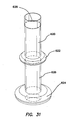
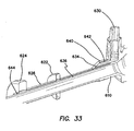
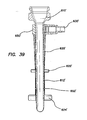
- a proximal winding thread 640 can encircle the proximal end of the retention mechanism 620 and compress the retention mechanism 620 into the proximal groove 642 to maintain the retention mechanism 620 on the cannula 610.
- a distal winding thread 644 can encircle the distal end of the retention mechanism 620 and compress the retention mechanism 620 into the distal groove to maintain the retention mechanism 620 on the cannula 610.
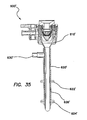
- the retention mechanism 620' comprises a fluid conduit fluidly coupling the inlet 630' to the inflatable member.
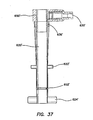
- the inlet housing 650' can comprise one or more fluid channels 636' ( FIG. 37 ) formed therein fluidly coupling the inlet 630' to the inflatable member.
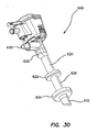
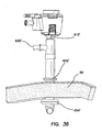
- This inflation of the balloons 622, 622', 624, 624' secures the cannula assembly 600, 600' to the abdominal or thoracic wall, reducing displacement of the cannula assembly 600, 600' during the surgery and/or instrument removal.
Description
- Trocar systems including cannulas and, more specifically, to trocars having a balloon retention device are provided. Trocar systems facilitate minimally invasive surgery across a body wall and within a body cavity. For example, in abdominal surgery, trocars provide a working channel across the abdominal wall to facilitate the use of instruments within the abdominal cavity.
- Trocar systems typically include a cannula, which provides the working channel, and an obturator that is used to place the cannula across a body wall, such as the abdominal wall. The obturator is inserted into the working channel of the cannula and pushed through the body wall with a penetration force of sufficient magnitude to result in penetration of the body wall. Alternatively, the cannula with an obturator is passed through an incision formed by the "Hassan," or cut-down, technique, which includes incremental incisions through the body wall until the body wall is incised through its entire thickness. Once the cannula has traversed the body wall, the obturator can be removed.
- With the cannula in place in the body wall, various instruments may be inserted through the cannula into the body cavity. One or more cannulas may be used during a procedure. During the procedure, the surgeon manipulates the instruments in the cannulas, sometimes using more than one instrument at a time. The manipulation of an instrument by a surgeon may cause frictional forces between the instrument and the cannula in which the instrument is inserted. These frictional forces may result in movement of the cannula in an inward or outward direction within the body wall. If the cannula is not fixed in place, the proximal or distal motions of the instruments through the cannula may potentially cause the cannula to slip out of the body wall or to protrude further into the body cavity, possibly leading to injury to the patient.
- The surfaces of the cannula associated with a trocar are generally smooth. The smoothness of a cannula surface makes placement of the cannula through a body wall relatively easy and safe. However, a smooth cannula may not have the desired retention characteristics once the cannula has been placed through a body wall. This may present problems as instruments and specimens are removed from a body cavity through the cannula and the associated seal systems of the trocar. It is highly desirable for a cannula to remain fixed in the most appropriate position once placed. Additionally, if the Hassan technique is used, the incision may be larger than the cannula that may be placed through the incision. Therefore, it can be desirable to provide a means to seal the incision site after the cannula has been inserted in order to insufflate a patient.
- Many solutions to the issue of trocar-cannula fixation or stabilization have been formed. These solutions include an inflatable balloon attached to the distal portion of the cannula with a thick foam bolster proximal to the insertion point into the body wall, raised threads or raised rings associated with the outer surface of the cannula, mechanically deployable enlarging portions arranged at the distal end of a cannula and suture loops or hooks associated with the proximal end of the trocar. These solutions have provided some degree of fixation or stabilization, but they have often led to cannulas having a larger outside diameter. Further, the thick foam bolster associated with balloon trocars has reduced the usable length of the cannula.
- Some prior art balloon trocars include a natural rubber latex balloon. Common laparoscopic surgeries may take up to four hours. The natural rubber latex balloons provide adequate air retention, thereby permitting proper balloon inflation during such a surgical procedure. However, many people are sensitive to latex and may be allergic to the balloon on the trocar. To accommodate those patients with allergies to latex, some prior art balloon trocars have the latex balloon coated with another material, such as silicone. The silicone coating reduces the likelihood of the patient being contacted by the latex. However, the silicone coating adds material thickness to the device, thereby increasing the outer profile of the device. Also, the patient may still be exposed to latex if the balloon ruptures or breaks during the surgical procedure.
-
US 2005/0054994 A1 andUS 2004/0230316 A1 describe devices in which an anchor balloon is placed in a patient's bladder and a blocking balloon is placed in the patient's urethra to close off the urethra from drainage,WO 2004/060463 discloses an expandable anchoring member for securing a location or pathway within a subarachnoid space,US 6,293,924 discloses a dilation catheter with an inflatable member having a first section to secure the catheter in a lumen and a second section to dilatate the lumen,US 2007/225643 discloses a balloon anchor for line anchoring a surgical instrument such as a trocar within a puncture opening and discloses an inflatable retractor system for receiving a cannula. - There remains a need for a cannula fixation or stabilization device that maintains the position of the cannula with respect to the body wall of the patient. Additionally, the cannula fixation or stabilization device may be removably attachable to the cannula.
- In some embodiments a cannula assembly is provided comprising a cannula, a retention mechanism, an inlet, and a fluid conduit. The cannula has a proximal end, a distal end, an outer surface, and a lumen extending between the proximal end and the distal end. The lumen is adapted to receive a medical instrument therein. The retention mechanism is attached to the outer surface of the cannula and has a proximal end and a distal end. The retention mechanism comprises a first inflatable balloon, a second inflatable balloon, and a mid-section. The first inflatable balloon is positioned near the distal end of the retention mechanism. The second inflatable balloon is positioned between the proximal end and the distal end of the retention mechanism. The mid-section extends between the first inflatable balloon and the second inflatable balloon. The mid-section has an outer surface adapted to contact a body wall of a patient when in use. The inlet is near the proximal end of the retention mechanism. The inlet is in fluid communication with the first and second balloons and the mid-section of the retention mechanism. The fluid conduit fluidly couples the inlet with the first and second inflatable balloons. The mid-section is configured such that upon application of an inflation fluid to the inlet, the first and second balloons inflate before the mid-section.
- In certain embodiments of the afore-described cannula assembly, at least one of the first and second balloons comprises a toroidal profile. In certain embodiments, both of the first and second balloons comprise a toroidal profile. In certain embodiments, at least one of the first and second balloons comprises a disc profile. In certain embodiments, both of the first and second balloons comprise a disc profile. In some embodiments, the fluid conduit comprises: an air inlet cavity fluidly coupled to the inlet; and a fluid channel extending generally longitudinally along the outer surface of the cannula. In certain embodiments, the inlet is integrally formed with the cannula. In certain embodiments, the retention mechanism is attached to the cannula by a proximal thread winding at the proximal end of the retention mechanism and a distal thread winding at the distal end of the retention mechanism.
- In certain embodiments of the afore-described cannula assembly, the retention mechanism comprises a double layered balloon comprising: an inner balloon layer adapted to be slidably advanced over the cannula; and an outer balloon layer having the first inflatable balloon and the second inflatable balloon formed thereon; and the fluid conduit comprises a fluid chamber defined between the inner balloon layer and the outer balloon layer. In certain embodiments, the inner balloon layer comprises a cannula retention surface configured to retain the cannula. In certain embodiments, the cannula retention surface comprises an inner balloon inflatable to retain the outer surface of the cannula. In some embodiments, the cannula assembly further comprises an inlet housing coupled to the proximal end of the retention mechanism, and wherein the inlet is formed in the inlet housing.
- In certain embodiments, a retention mechanism for a cannula assembly is provided comprising an inlet housing and an inflatable member. The inlet housing comprises an annular member and an inlet port. The annular member has an opening adapted to receive the cannula assembly. The inlet port is adapted to receive a source of inflation fluid. The inflatable member has a proximal end and a distal end. The proximal end of the inflatable member is fluidly coupled to the inlet port of the inlet housing. The inflatable member comprises an inner layer, an outer layer, and a fluid chamber. The inner layer defines a generally cylindrical surface adapted to receive the cannula assembly therein. The outer layer comprises a first inflatable projection and a second inflatable projection. The first inflatable projection is positioned near the distal end of the inflatable member. The second inflatable projection is positioned between the proximal end and the distal end of the inflatable member and spaced apart from the first inflatable projection. The fluid chamber is formed between the inner layer and the outer layer and is fluidly coupled to the inlet port.
- In certain embodiments of retention mechanism, the inner layer of the inflatable member comprises a retention feature extending radially inwardly therefrom and configured to retain the cannula assembly. In certain embodiments, the retention feature comprises an inflatable balloon. In certain embodiments, the first inflatable projection and the second inflatable projections each comprise an inflatable balloon. In certain embodiments, the inflatable projection and the second inflatable projections each define a generally annular structure in an inflated state. In certain embodiments, the inlet port of the inlet housing is coupled to the annular member, and the annular member comprises fluid conduits fluidly coupled to the inlet port and fluidly coupled to the inflatable member. In certain embodiments, the inlet housing comprises a rigid material.
- In certain embodiments, a cannula assembly is provided comprising a cannula and a retention mechanism. The cannula has a proximal end, a distal end, an outer surface, and a lumen extending between the proximal end and the distal end. The lumen is adapted to receive a medical instrument therein. The cannula comprises an inlet port and a fluid conduit. The inlet port is on the outer surface of the cannula. The fluid conduit extends generally longitudinally in the outer surface of the cannula. The fluid conduit is fluidly coupled to the inlet port. The retention mechanism is coupled to the outer surface of the cannula. The retention mechanism has a proximal end and a distal end. The retention mechanism comprises a first inflatable balloon and a second inflatable balloon. The first inflatable balloon is positioned near the distal end of the retention mechanism. The second inflatable balloon is positioned between the proximal end and the distal end of the retention mechanism. The first and second inflatable balloons are fluidly coupled to the fluid conduit on the cannula.
- In certain embodiments of cannula assembly, the cannula further comprises an inlet dome formed on the outer surface thereof, the inlet dome defining an inlet chamber fluidly coupled to the inlet port and the fluid conduit. In certain embodiments, the inlet port comprises a check valve positioned therein, the check valve adapted to receive a syringe of fluid. In certain embodiments, the cannula further comprises a proximal groove and a distal groove and the retention mechanism further comprises a proximal thread winding at the proximal end of the retention mechanism and a distal thread winding at the distal end of the retention mechanism, the proximal thread winding coupling the retention mechanism to the proximal groove, and the distal thread winding coupling the retention mechanism to the distal groove. In certain embodiments, the first and second inflatable balloons each comprise a generally annular balloon. In certain embodiments, the second inflatable balloon has a smaller inflated volume than the first inflatable balloon.
- In certain embodiments, a method of securing a cannula assembly for a laparoscopic procedure on a patient comprises providing a cannula assembly, inserting the cannula assembly into an incision in the patient, and inflating balloons on the cannula assembly. The cannula assembly comprises a cannula, a retention mechanism, an inlet, and a fluid conduit. The cannula has a proximal end, a distal end, an outer surface, and a lumen extending between the proximal end and the distal end. The lumen is adapted to receive a medical instrument therein. The retention mechanism is attached to the outer surface of the cannula and has a proximal end and a distal end. The retention mechanism comprises a first inflatable balloon, a second inflatable balloon, and a mid-section. The first inflatable balloon is positioned near the distal end of the retention mechanism. The second inflatable balloon is positioned between the proximal end and the distal end of the retention mechanism. The mid-section extends between the first inflatable balloon and the second inflatable balloon. The mid-section has an outer surface adapted to contact a body wall of a patient when in use. The inlet is near the proximal end of the retention mechanism. The inlet is in fluid communication with the first and second balloons and the mid-section of the retention mechanism. The fluid conduit fluidly couples the inlet with the first and second inflatable balloons. The mid-section is configured such that upon application of an inflation fluid to the inlet, the first and second balloons inflate before the mid-section. Inserting the cannula assembly into an incision comprises inserting the cannula assembly into an incision in the patient until the first inflatable balloon is positioned in a body cavity of the patient and the second inflatable balloon is outside of the incision of the patient. Inflating balloons on the cannula assembly comprises inflating the first and second inflatable balloons.
- In certain embodiments of the method, inflating the first and second inflatable balloons comprises introducing a source of inflation fluid to the inlet of the cannula assembly. In certain embodiments, the source of inflation fluid comprises a syringe of air. In certain embodiments, providing the cannula assembly further comprises attaching the retention mechanism to the outer surface of the cannula. In certain embodiments, attaching the retention mechanism to the outer surface of the cannula comprises slidably advancing the retention mechanism over the outer surface of the cannula.
-
-
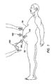
FIG. 1 is a side view of a laparoscopic surgical procedure; -
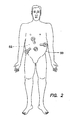
FIG. 2 is a plan view of a laparoscopic surgical procedure showing the placement of trocars; -
FIG. 3 is a perspective view of a prior art assembled trocar and obturator; -
FIG. 4 is a perspective view of a prior art assembled trocar without an obturator; -
FIG. 5 is a perspective view of a prior art cannula; -
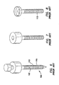
FIG. 6 is a perspective view of a prior art assembled threaded trocar and obturator; -
FIG. 7 is a perspective view of a prior art threaded cannula and housing; -
FIG. 8 is a perspective view of a prior art threaded cannula; -
FIG. 9 is a perspective view of a prior art cannula having an uninflated balloon at the distal end; -
FIG. 10 is a perspective view of a prior art cannula having an inflated balloon at the distal end; -
FIG. 11 illustrates a prior art trocar-cannula having a distal retention balloon placed through a body wall in a first position; -
FIG. 12 illustrates a prior art trocar-cannula having a distal retention balloon placed through a body wall in a second position; -
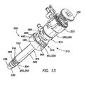
FIG. 13 is a perspective view of a balloon trocar having a bolster; -
FIG. 14 is a perspective view of a cannula portion of the balloon trocar ofFIG. 13 ; -
FIG. 15 is a perspective view of a sleeve portion of the balloon trocar ofFIG. 13 ; -
FIG. 16 is a partial plan view in cross section depicting the cannula portion, the sleeve portion, a seal, and an obturator of the balloon trocar ofFIG. 13 ; -
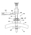
FIG. 17 illustrates a cannula assembly placed through a body wall; -
FIG. 18 is a partial plan view in cross section similar toFIG. 16 and including a port portion of the sleeve portion of the balloon trocar; -
FIG. 19 is a partial plan view in cross section depicting a distal portion of the cannula portion, sleeve portion, obturator and a balloon coupled between the cannula portion and sleeve portion by windings of thread; -
FIG. 20 is a plan view in cross section depicting the balloon trocar; -
FIG. 21 is a partial plan view in cross section depicting a distal portion of the cannula portion, sleeve portion, obturator and the balloon coupled between the cannula portion and sleeve portion with a balloon having a second layer; -
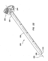
FIG. 22 is a perspective view of the obturator; -
FIG. 23 is a perspective view of a base portion of the bolster ofFIG. 13 ; -
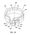
FIG. 24 is a perspective view of a collar portion of the bolster ofFIG. 13 ; -
FIG. 25 is a perspective view of a lever portion of the bolster ofFIG. 13 ; -
FIG. 26 is a side view of the bolster ofFIG. 13 ; -
FIG. 27 is a perspective view of the bolster coupled to the sleeve portion of the balloon trocar;FIG. 28 is an end perspective view of the bolster ofFIG. 13 ; -
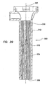
FIG. 29 is a plan view, in cross section of a sleeve portion of the balloon trocar ofFIG. 13 with an inner surface of the sleeve including channels; -
FIG. 30 is a perspective view of one embodiment of a cannula assembly including a retention mechanism for advanced fixation; -
FIG. 31 is a perspective view illustrating the retention mechanism of the cannula assembly ofFIG. 30 ; -
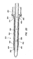
FIG. 32 is a perspective view illustrating a cannula of the cannula assembly ofFIG. 30 ; -
FIG. 33 is a longitudinal cross-sectional view of the cannula assembly ofFIG. 30 ; -
FIG. 34 is one embodiment of a cannula assembly having a cannula and a retention mechanism; -
FIG. 35 is a longitudinal cross-sectional view of the cannula assembly ofFIG. 34 ; -
FIG. 36 is a perspective view of the cannula assembly ofFIG. 34 placed through a body wall; -
FIG. 37 is a longitudinal cross-sectional view of the retention mechanism of the cannula assembly ofFIG. 34 ; -
FIG. 38 is a partial cross-sectional view of the retention mechanism of the cannula assembly ofFIG. 34 ; -
FIG. 39 is a longitudinal cross-sectional view of the cannula assembly ofFIG. 34 ; -
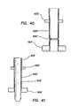
FIG. 40 is a longitudinal cross-sectional view of a distal end of the retention mechanism of the cannula assembly ofFIG. 34 ; and -
FIG. 41 is a longitudinal cross-sectional view of a distal end of the retention mechanism of the cannula assembly ofFIG. 34 with a cannula inserted therein. - With reference to
FIGS. 1 and2 , a typical laparoscopic procedure is illustrated where a plurality oftrocars 100 are placed through abody wall 50, such as an abdominal wall, and into abody cavity 52, such as an abdominal cavity. Thebody cavity 52 is insufflated, or inflated with gas, to distend thebody wall 50 and provide a working space for the laparoscopic procedure. Thetrocars 100 each include acannula 110 and aseal 150. Positive pressure is maintained within thebody cavity 52 by theseal 150 associated with thecannula 110. In addition, thecannula 110 must form a gas-tight seal against adjacent tissue. If positive pressure is lost, either through theseal 150 associated with thecannula 110 or the seal between the cannula and the adjacent tissue, the procedure may be compromised. - As the
body cavity 52 is inflated, thebody wall 50 may be greatly distended. The access sites may tend to enlarge under the distention of thebody wall 50 and compromise the positioning and sealing of thecannula 110. As stated above, the manipulation ofinstruments 190 used through thetrocars 100 may result in movement of thecannulas 110 in either a proximal or distal direction within the access site through thebody wall 50. As this occurs, some liquefaction may take place and the preferred relationship between thecannula 110 and the body tissue may be compromised. - Referring now to
FIGS. 3-6 , a typical assembledtrocar 100 is shown having acannula 110, aseal housing 150 and anobturator 160. Thecannula 110 typically has a smoothexterior surface 102 so that it may be inserted through thebody wall 50 easily. Theseal housing 150 contains a seal system that prevents retrograde gas-flow. Theobturator 160 is a cutting or piercing instrument that creates the pathway through thebody wall 50 through which thecannula 110 follows.Surgical obturators 160 are generally sized and configured to create a defect in tissue that is appropriate for the associatedcannula 110. However, the defect may have a tendency to enlarge during a surgical procedure as thetrocar 100 orcannula 110 is manipulated. As aninstrument 190 is urged distally and proximally, or inserted and withdrawn, thecannula 110 may move or even be inadvertently withdrawn due to the friction between theinstrument 190 and theseal 150 of the trocar housing. - With specific reference to
FIGS. 6-8 , atrocar 100 or access device is shown where theouter surface 102 of thecannula 110 includes a plurality of raised features 115. These raised features 115 are sized and configured to increase resistance to proximal and distal motion asinstruments 190 are maneuvered, and especially as specimens are removed, through thetrocar 100. The prior art includes either sequential raised rings or a raised coarse-thread 115. While the rings orthreads 115 of the prior art may stabilize thecannula 110 to some degree, they do not necessarily seal thecannula 110 against the adjacent tissue of abody wall 50. There may be gas loss associated with the use of these systems. The raised rings orthreads 115 also increase the insertion force required to penetrate abody wall 50. The insertion force may be reduced in the instance of a continuouscoarse thread 115 in comparison to a sequence of discrete raised rings or features as a threadedcannula 110 may actually be "screwed" into the tissue defect in accordance with the thread direction and pitch, rather than pushed through without appropriate rotation. - With reference to
FIGS. 9-12 , asurgical access device 100 according to prior art includes acannula 110 having aninflatable balloon 120 associated with the distal-end portion 122 of the cannula. Theballoon 120 is sized and configured to fit snugly around thecannula 110 in the uninflated condition. Theballoon 120,is inflated after thecannula 110 is properly placed through thebody wall 50 and into thebody cavity 52. Theballoon 120 is generally held against theinterior surface 54 of thebody wall 50 by a counter-force that is associated with a sliding counter-force member, such as a foam bolster 180. The bolster 180 is associated with the proximal portion of thecannula 110. Theballoons 120 associated with the devices of the prior art are typically "thick-walled" structures constructed as part of thecannula 110. Theballoon 120 is generally bonded to the distal-end portion 122 of thecannula 110 and an inflation channel or lumen is provided within the wall of thecannula 110. Referring toFIG. 13 , one aspect of theballoon trocar 200 includes acannula assembly 210, atrocar seal 220 and anobturator 230. Thecannula assembly 210 includes acannula 250 and anouter sleeve 300. - Referring to
FIG. 14 , thecannula 250 includes a substantiallylongitudinal tube 252 having aproximal end 254, adistal end 256, and alumen 258 therebetween. Thecannula 250 may include at least aproximal portion 260 having a first, larger periphery and adistal portion 262 having a second, smaller periphery. In one aspect, theproximal portion 260 anddistal portion 262 of thecannula 250 may each include a substantially cylindrical portion, with theproximal portion 260 having a first, larger circumference and thedistal portion 262 having a second, smaller circumference. Thecannula 250 may also include atransition region 264 between theproximal portion 260 and thedistal portion 262. Thelumen 258 of thecannula 250 may be substantially smooth and configured to accept the obturator 230 (seeFIG. 13 ). Theproximal portion 260 of thecannula 250 may be configured to accept the trocar seal 220 (seeFIG. 13 ). The outer surface of thedistal portion 262 of thecannula 250 includes anannular groove 266 toward thedistal end 256 of the distal portion of the cannula. Theannular groove 266 may lie within a plane that is substantially perpendicular to alongitudinal axis 272 of thecannula 250. Additionally, the outer surface of thedistal portion 262 of thecannula 250 includes a plurality ofchannels 268 extending along the length of the cannula from substantially the proximal end of the distal portion of the cannula distally to a point proximal to theannular groove 266 near thedistal end 256 of the distal portion of the cannula. The plurality ofchannels 268 is adapted to facilitate the flow of gasses or fluids therethrough. In one aspect, the plurality ofchannels 268 may include a plurality of substantiallylongitudinal grooves 270 that are substantially parallel to thelongitudinal axis 272 of thecannula 250. In one aspect, thecannula 250 may be made of a polymeric material, such as a polycarbonate material. - Referring to
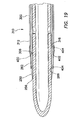
FIG. 15 , theouter sleeve 300 of thecannula assembly 210 includes a substantiallylongitudinal tube 302 having aproximal end 304, adistal end 306, and alumen 308 therebetween. Thesleeve 300 may also include at least aproximal portion 310 having a first, larger periphery and adistal portion 312 having a second, smaller periphery. In one aspect, theproximal portion 310 anddistal portion 312 of thesleeve 300 may each include a substantially cylindrical portion, with theproximal portion 310 having a first, larger circumference and thedistal portion 312 having a second, smaller circumference. Thesleeve 300 may include atransition region 314 between theproximal portion 310 and thedistal portion 312. Thelumen 308 of thesleeve 300 is configured to accept the cannula 250 (seeFIG. 13 ) and may be substantially smooth. Anouter surface 322 of thedistal portion 312 of thesleeve 300 includes anannular groove 316 toward thedistal end 306 of the distal portion of the sleeve. Theannular groove 316 may lie within a plane that is substantially perpendicular to alongitudinal axis 320 of thesleeve 300. In one aspect, thesleeve 300 may be made of a polymeric material, such as a polycarbonate. - Referring again to
FIG. 13 , with thesleeve 300 positioned over thecannula 250, theproximal portion 310 of thesleeve 300 fits over at least a distal region of theproximal portion 260 of the cannula and thedistal portion 312 of the sleeve fits over at least a portion of thedistal portion 262 of the cannula. Additionally, with thesleeve 300 positioned over thecannula 250, thedistal end 306 of thesleeve 300 is positioned proximal to a distal end of the plurality ofchannels 268 on the outer surface of thecannula 250. - As stated above, the
cannula assembly 210 includes thecannula 250 and thesleeve 300. Referring now toFIG. 16 , to substantially prevent gas or fluid from leaking between theproximal end 304 of thesleeve 300 and theproximal portion 260 of thecannula 250, a seal, such as an o-ring 350, may be positioned between the cannula and the sleeve. In one aspect the seal, such as the o-ring 350, is positioned between the outer surface of thecannula 250 and the inner surface of thesleeve 300. In another aspect, the outer surface of the distal region of theproximal portion 260 of thecannula 250 may include a substantially flat surface, such as a planar surface or a chamfered surface, which communicates between theproximal portion 260 of the cannula and either thetransition region 264 or thedistal portion 262 of the cannula. Similarly, the inner surface of the distal region of theproximal portion 310 of thesleeve 300 may include a substantially flat surface, such as a planar surface or a chamfered surface, which communicates between theproximal portion 310 of the sleeve and either thetransition region 314 or thedistal portion 312 of the sleeve. In this aspect, the seal, such as the o-ring 350, is positioned between the flat surface on the outer surface of the distal region of theproximal portion 260 of thecannula 250 and the flat surface on the inner surface of the distal region of theproximal portion 310 of thesleeve 300. - Referring to
FIGS. 13-17 , thecannula 250 and thesleeve 300 are coupled together at theproximal portion 260 of the cannula and theproximal portion 310 of the sleeve at a position proximal to the seal, such as the o-ring 350. In one aspect, the means for coupling theproximal portion 260 of thecannula 250 and theproximal portion 310 of thesleeve 300 includes a snap fitting 360 having at least oneprojection 362 on the outer surface of the cannula and at least onenotch 364 on the inner surface of the sleeve. Alternatively, the projection may be on the inner surface of the sleeve and the notch may be on the outer surface of the cannula. The at least oneprojection 362 and the at least onenotch 364 are positioned such that when the projection is positioned within the notch, the seal, such as the o-ring 350, is compressed sufficiently to form a seal between thecannula 250 and thesleeve 300. In one aspect, the seal, such as the o-ring 350, is made from a soft, compressible material. In one aspect, the o-ring 350 is made of a silicone having a hardness of about 40 Shore A. In one aspect, the snap fitting 360 includes twoprojections 362 positioned substantially circumferentially opposite each other on the outer surface of the cannula and twonotches 364 positioned substantially circumferentially opposite each other on the inner surface of thesleeve 300. Other means for coupling thesleeve 300 to thecannula 250 that are well known in the art may also be used, such as other mechanical means or adhesive bonding. - Referring to
FIGS. 14 ,15 and18 , thecannula assembly 210 also includes a locking means 370 to substantially prevent, or minimize, thecannula 250 and thesleeve 300 from rotating relative each other about thelongitudinal axes projection 372 on the outer surface of thecannula 250 and achannel 374 on the inner surface of thesleeve 300. In one aspect, theprojection 372 is positioned on the outer surface of theproximal portion 260 of thecannula 250 and thechannel 374 is positioned on the inner surface of theproximal portion 310 of thesleeve 300 and extends to theproximal end 304 of the sleeve. Alternatively, theprojection 372 may be positioned on the inner surface of theproximal portion 310 of thesleeve 300 and thechannel 374 may be positioned on the outer surface of theproximal portion 260 of thecannula 250. If thechannel 374 is positioned on thesleeve 300, the channel may either be through the entire thickness of the wall of the sleeve or through only a portion of the thickness of the wall of the sleeve. To substantially prevent or minimize rotation between thecannula 250 and thesleeve 300, thechannel 374 is substantially longitudinal and substantially parallel to theaxis 320 of thesleeve 300. Theprojection 372 may include any shape that fits within the walls of thechannel 374 and facilitates the prevention or minimization of rotation between thecannula 250 and thesleeve 300. In one aspect, theprojection 372 is substantially cylindrical while in another aspect the projection is substantially rectangular. - Referring to
FIG. 19 , thecannula assembly 310 also includes aballoon 400. In one aspect, the balloon includes atubular sleeve 402. Thetubular sleeve 402 may include an elastomeric material. Elastomeric materials that may be used to make theballoon 400 include silicone, polyisoprene, and urethane. In other aspects, theballoon 400 may be made of other materials, such as MYLAR, that may be folded onto thecannula 250 andsleeve 300 and inflated into a larger profile. Theballoon 400 may be cut to length prior to installation onto thecannula 250 andsleeve 300 such that the balloon is sufficiently long to extend between and cover theannular grooves distal portions balloon 400 is slid over thedistal end 256 of thecannula 250 and thedistal end 306 of thesleeve 300 until it covers theannular grooves - In one aspect, the
balloon 400 is fixed in place by windingthread 404 around the balloon in the areas that overlap of theannular grooves distal portions cannula 250 andsleeve 300. Winding theballoon 400 withthread 404 forces the portion of the balloon that overlaps theannular grooves grooves balloon 400 into theannular grooves cannula 250 andsleeve 300 at the windings, thereby making thecannula assembly 210 substantially smooth. Furthermore, forcing theballoon 400 into theannular grooves windings 404 also forms a seal between the balloon and thecannula 250 and between the balloon and thesleeve 300. - Referring to
FIG. 20 , the space between the outer surface of thecannula 250 with the channels 268 (seeFIG. 14 ), the inner surface of thesleeve 300, the o-ring 350, and theballoon 400 with thewindings 404 form a substantiallyclosed chamber 408. In one aspect, thechannels 268 on the outer surface of thecannula 250 are formed into the wall of the cannula so as not to increase the overall thickness of the wall of a standard cannula. Thelumen 308 of thesleeve 300 may be configured to provide minimal space between thedistal portion 312 of the sleeve and thedistal portion 262 of thecannula 250, thereby minimizing the overall profile of thecannula assembly 210. The gap between thetransition regions cannula 250 and thesleeve 300 may be larger than the gap between thedistal portions channels 268 on the outer surface of thecannula 250 during inflation and deflation of the balloon. - The
balloon 400 may be made to take on one of many different shapes upon inflation of the balloon. In one aspect, theballoon 400 may include a substantially toroid shape upon inflation. In another aspect, the balloon may include a disc shape upon inflation. In another aspect, theballoon 400 may be a fluted balloon. In one aspect, different shapes for theballoon 400 may be attained by varying the thickness about thetubular sleeve 402 that forms the balloon or by pre-molding a different shape for the balloon. - The
balloon 400 should have sufficient impermeability properties to substantially prevent inflation gas or fluid from permeating through a wall of the balloon. Additionally, the balloon should bias toward a deflated state during deflation of the balloon. Referring toFIG. 21 , anouter layer 406 may be positioned and fixed over the balloon when using a balloon material that does not possess adequate properties to bias the balloon toward deflation. Theouter layer 406 may include silicone, latex, polyisoprene, rubber, or other biocompatible elastomeric materials that are well known in the art. Theouter layer 406 may be wound onto thecannula 250 andsleeve 300 together with theballoon 400, as described above. - Some elastomeric materials for the
balloon 400 possess inadequate impermeability properties to enable balloons made of such materials to be used without first sealing the pores in the balloon material. For example, aballoon 400 formed of silicone will have adequate properties to bias the balloon toward deflation, but it may be too porous to maintain adequate inflation for the term of a surgical procedure. In some embodiments, the inner surface of the balloon may be coated with grease to seal the pores in the balloon. In one aspect, the balloon may be formed of a porous material, such as silicone, and the grease may be silicone grease. The silicone may have adequate properties to bias the balloon toward deflation, but it may be too porous to be used independent of an additional sealing means. The silicone grease serves to seal the pores of the balloon, thereby extending the inflation time of the balloon. - To prevent or minimize the likelihood of a crease forming and creating a leak path when winding the ends of the
balloon 400 with the winding 404, the periphery of the inside surface of the balloon should be about equal to, or smaller than, the periphery of theannular groove 266 on thecannula 250. In this manner, the balloon is stretched onto thecannula 250 andsleeve 300 and the ends of theballoon 400 fit snugly into theannular grooves annular grooves balloon 400 will crease when thewindings 404 are applied to the balloon. However, the stretching action to place theballoon 400 onto thecannula 250 andsleeve 300 may cause uneven stretching about the perimeter of the balloon that may result in asymmetric inflation of the balloon. By applying grease to the inner surface of theballoon 400 prior to placing the balloon onto thecannula 250 andsleeve 300, the grease acts as a lubricant and permits the balloon to slide more easily over the cannula and sleeve, thereby improving assembly, and to rotate back toward a natural position about the perimeter of the balloon, thereby providing for substantially symmetric inflation of the balloon. In other words, the grease allows the balloon to substantially self-center itself, thereby substantially equalizing the stresses within the balloon material and allowing for substantially symmetric inflation of the balloon. - By applying the grease to the inner surface of the
balloon 400, rather than adding an additional layer to the balloon, increases in the outer profile of the balloon are minimized. Using asilicone balloon 400 with silicone grease limits the introduction of potentially allergic materials, such as latex. - Referring again to
FIG. 18 , thesleeve 300 includes aninflation port 380 positioned to be distal to the seal, such as the o-ring 350. Theinflation port 380 provides a pathway for gas or fluid to be introduced and removed from thechamber 408. In one aspect, theinflation port 380 may include a normally closedcheck valve 382 having a spring-loadedplunger 384. In a further aspect, thecheck valve 380 may include aLuer lock 386. It is contemplated that other inflation ports that are well known in the art may be used. - Referring again to
FIG. 13 , thetrocar seal 220 may include a valve that provides an instrument seal in the presence of an instrument, such as theobturator 230, and a zero-seal in the absence of an instrument. Thetrocar seal 220 may also be removable from thecannula assembly 210. Removal of thetrocar seal 220 is useful for tissue removal through thecannula assembly 210 and for rapid release of insufflation gasses. - Referring to
FIG. 22 , theobturator 230 includes anelongate shaft 232 extending along a substantiallylongitudinal axis 234 between aproximal end 236 and adistal end 238. Adistal tip 240 of theelongate shaft 232 may include a prolate spheroid shape. Theelongate shaft 232, including thedistal tip 240, is sized and configured to slide within thelumen 258 of the cannula 250 (seeFIGS. 16 and19 ). Aproximal portion 242 of theobturator 230 may include ahandle portion 244 having a larger periphery than theelongate shaft 232 to facilitate advancing and retracting the obturator within thelumen 258 of thecannula 250. In an operative position, thedistal tip 240 of theobturator 230 is positioned distal to thedistal end 256 of thecannula 250 and thehandle portion 244 of the obturator is positioned proximal to theproximal end 254 of the cannula. - The
obturator 230 may be made of a polymeric material, such as a polycarbonate. Those familiar with the art will recognize that theobturator 230 may be made of other materials that are well known in the art and are considered within the scope of the present invention. In comparison to obturators having distal tips with a spheroid shape, thedistal tip 240 of theobturator 230 having a prolate spheroid shape requires a lower insertion force to insert the trocar into a body through an incision within a body wall. The prolate spheroid shape of thedistal tip 240 of theobturator 230 also reduces the likelihood of injuring tissue or organs within the body cavity, in comparison to obturators having distal tips with a more pointed shape. Using theobturator 230 having adistal tip 240 with a prolate spheroid shape, the surgeon can merely nick the peritoneum and dilate or stretch the incision open with the distal tip of the obturator. - Referring again to
FIG. 13 , a bolster 410 may be used in conjunction with theballoon trocar 200 to assist the balloon to seal around an incision in thebody wall 50 through which the balloon trocar is to be inserted with the balloon sealing the incision from within thebody cavity 52. The bolster 410 is configured to perform as a cannula fixation device on the outside of the body while theballoon 400 acts as a cannula fixation device on the inside of the body. The bolster 410 is slidably adjustable along the length of thecannula assembly 210 proximal to theballoon 400 and includes a clamping device for locking the bolster in position along the length of the cannula assembly. Theballoon 400, on the other hand, is fixed at a location along the length of thecannula assembly 210 and seals against the inner surface of the abdominal wall. - To facilitate the clamping features of the bolster 410, the bolster includes a
base 420 and aclamping mechanism 415. Theclamping mechanism 415 includes anadjustable collar 460 and alever 500. The bolster also includes apad 530 including a substantially incompressible gel material. The clamping features utilize an over-center lock design to maintain the bolster 410 in a fixed position along the length of thecannula assembly 210. - Referring to
FIG. 23 , thebase 420 includes asleeve 422 projecting distally from aflange 424. Theflange 424 includes aproximal surface 428 and adistal surface 430. Theproximal surface 428 and thedistal surface 430 of theflange 424 are substantially parallel to each other and substantially perpendicular to anaxis 432 of thebase 420. Although theflange 424 is shown as being flat, other shapes, such as rounded shapes, may be used and are contemplated as within the scope of the invention. Thesleeve 422 portion of thebase 420 includes aproximal end 434, adistal end 436, and alumen 438 therebetween. Thelumen 438 is sized to receive and slidably engage thesleeve 300 of thecannula assembly 210. An outer surface 440 of thesleeve 422 portion of the base 420 may include a substantially cylindrical shape. Thelumen 438 of thesleeve 422 portion of thebase 420 extends through theflange 424, thereby forming anaperture 442 in the flange. - A
clamp receptacle 444 extends proximally from theproximal surface 428 of theflange 424. Theclamp receptacle 444 includes at least oneriser 446 extending from theproximal surface 428 of theflange 424 and aplatform 448 extending from the at least oneriser 446. In one aspect, theclamp receptacle 444 includes a first riser 450 and asecond riser 452 with theplatform 448 extending between the first and second risers. Theplatform 448 is shaped so as to not extend over theaperture 442 in theflange 424. In other words, theplatform 448 provides clearance for thecannula assembly 210 such that the bolster 410 may slidably engage the cannula assembly without the platform interfering with the engagement. Theplatform 448 includes adistal surface 454 that is substantially parallel to theproximal surface 428 of theflange 424. As will be described below, the distance between thedistal surface 454 of theplatform 448 and theproximal surface 428 of theflange 424 is sufficient to receive theclamp mechanism 415 portion of the bolster 410. Thedistal surface 454 of the platform includes a substantiallylinear slot 456 extending radially therethrough. In one aspect, the base may be made of a polymeric material, such as a polycarbonate. However, it is contemplated that other materials, such as metals and composites, may be used. - Referring to
FIG. 24 , thecollar 460 portion of theclamping mechanism 415 of the bolster 410 includes a substantiallycircumferential ring 462 defining asplit 464. Thecollar 460 further includes aproximal end 466, adistal end 468, and aninner surface 470. Theinner surface 470 of thecollar 460 may include a counterbore configuration forming aledge 472 therein. Thesplit 464 in thecollar 460 forms afirst end 474 of thecollar 460 and asecond end 476 of the collar. Thecollar 460 is flexible in order to adjust the fit of the collar over thecannula assembly 210. More particularly, thefirst end 474 and thesecond end 476 of the collar may be brought closer together to create sufficient friction between the bolster 410 and thecannula assembly 210 to substantially fix the bolster in place along the length of the cannula assembly. Thefirst end 474 and thesecond end 476 of the collar may also be spread apart to reduce or substantially eliminate the friction between the bolster 410 and thecannula assembly 210 so that the bolster may slide along the length of the cannula assembly. - To facilitate control of the distance between the
first end 474 and thesecond end 476 of thecollar 460, afirst tab 478 extends from thefirst end 474 of the collar and asecond tab 480 extends from thesecond end 476 of the collar. In one aspect, the first andsecond tabs second tabs first tab 478 includes afirst aperture 482 extending longitudinally therethrough and thesecond tab 480 includes asecond aperture 484 extending longitudinally therethrough. The first andsecond apertures axis 486 of thecollar 460. As will be discussed below, thelever 500 interacts with thetabs collar 460. The collar may be made of a polymeric material, such as polycarbonate. However, it is contemplated that other materials, such as metals and composites, may be used. - Referring to
FIG. 25 , thelever 500 includes anarm 502 having a first,proximal surface 504, a second,distal surface 506, afirst end 508 and a second end 510. The proximal anddistal surfaces arm 502 are substantially parallel to each other. A substantially cylindricalfirst pin 512 extends proximally from theproximal surface 504 of thearm 502 proximate thefirst end 508 and a substantially cylindricalsecond pin 514 extends distally from thedistal surface 506 proximate the first end. The first andsecond pins distal surfaces arm 502. Anaxis 516 of thefirst pin 512 and anaxis 518 of thesecond pin 514 are substantially parallel to each other, but are also offset from each other. In one aspect, thefirst pin 512 is closer to thefirst end 508 of thearm 502 than is thesecond pin 514. The peripheries of the first andsecond pins second apertures tabs collar 460. In one aspect, there may be atab 520 positioned at the second end of thearm 502 to facilitate rotation of thelever 500 when it is assembled into the bolster 410. - Referring to
FIG. 26 , there is aspace 488 between a distal surface of thefirst tab 478 of thecollar 460 and a proximal surface of thesecond tab 480 of the collar. In one aspect, the distal surface of thefirst tab 478 and the proximal surface of thesecond tab 480 are substantially flat, substantially parallel to each other and substantially perpendicular to theaxis 486 of thecollar 460. Thespace 488 is sized to receive thearm 502 of thelever 500. Thelever 500 is coupled to thecollar 460 by manipulating thearm 502 of the collar into thespace 488 between the first andsecond tabs first pin 512 of the lever into the first aperture 482 (seeFIG. 24 ) in thefirst tab 478 of thecollar 460 and inserting the second pin 514 (seeFIG. 25 ) of the lever into the second aperture 484 (seeFIG. 24 ) in thesecond tab 480 of the collar. In this manner, thelever 500 is pivotally coupled to thecollar 460. In one aspect, thefirst pin 512 of the lever is sufficiently long to extend beyond the proximal surface of thefirst tab 478 of thecollar 460, while thesecond pin 514 is substantially flush or below flush with the distal surface of thesecond tab 480 of the collar. - With reference to
FIG. 27 and continued reference toFIG. 26 , to couple theclamping mechanism 415, including thecollar 460 andlever 500, to thebase 420, the collar and lever are inserted into theclamp receptacle 444 portion of the base. More particularly, theclamping mechanism 415 is inserted between theproximal surface 428 of theflange 424 portion of thebase 420 and thedistal surface 454 of theplatform 448 of theclamp receptacle 444 portion of the base such that thecollar 460 is nested between theflange 424, theplatform 448, and the at least oneriser 446 portion of theclamp receptacle 444. Further, the first andsecond tabs collar 460 and the first andsecond pins 512, 514 (seeFIGS. 24 and25 ) of thelever 500 are positioned between theproximal surface 428 of theflange 424 portion of thebase 420 and thedistal surface 454 of theplatform 448. The distance between theproximal surface 428 of theflange 424 portion of thebase 420 and thedistal surface 454 of theplatform 448 is sufficient for theclamp mechanism 415 to slidably engage within theclamp receptacle 444, yet also sufficiently low to maintain thelever 500 andcollar 460 of theclamp mechanism 415 in an engaged relationship with each other during activation of the lever to maintain the clamping force of the collar against thecannula assembly 210. In one aspect, thefirst pin 512 of thelever 500, which extends proximally beyond the proximal surface of thefirst tab 478, is positioned within theslot 456 on thedistal surface 454 of theplatform 448 to facilitate maintaining the position of the first andsecond tabs collar 460 and the first andsecond pins lever 500 between theproximal surface 428 of theflange 424 portion of thebase 420 and thedistal surface 454 of theplatform 448. - Referring to
FIGS. 13 and27 , the bolster 410 is slidably mounted onto thecannula assembly 210 by inserting thedistal end 256 of the cannula distally through theproximal end 466 of thecollar 460, through the aperture 442 (seeFIG. 23 ) of theflange 424 of thebase 420, and through the sleeve 422 (seeFIG. 23 ) of the base. The bolster 410 andcannula assembly 210 are slid relative to each other until thedistal end 436 of the sleeve 422 (seeFIG. 23 ) of thebase 420 is proximal to the balloon 400 (seeFIG. 19 ). - Referring to
FIG. 28 , when viewing theproximal end 466 of thecollar 460 and lever 500 (looking distally), the distance between the first and second ends 474, 476 of the collar is at its maximum when the lever is in a first, clockwise position. Rotating thelever 500 in a counter clockwise direction moves the first and second ends 474, 476 of thecollar 460 closer together, reducing the circumference of the collar and tightening the collar against the cannula assembly 210 (seeFIG. 13 ). The change in circumference of thecollar 460 as thelever 500 is rotated is caused by the offset between thefirst pin 512 and thesecond pin 514 of the lever (seeFIG. 25 ). The circumference of thecollar 460 is at its smallest when the lever is rotated about 180o from the first position. To facilitate the over-center lock design features of theclamping mechanism 415, thelever 500 is rotated from the first position more than about 180o to a second position. In this manner, as thelever 500 is rotating from the first position, the circumference of thecollar 460 reduces until the lever has rotated about 180o, then expands slightly until the lever is positioned at the second position. With thelever 500 in the second position, higher pressure is initially required to rotate the lever away from the second position in a clockwise direction to the first position because the circumference of thecollar 460 is reduced until the lever reaches the position that is about 180o from the first position. The higher pressure that is required protects against inadvertent release of theclamp mechanism 415. Although theclamp mechanism 415 was described in detail, those familiar in the art will recognize that other clamp mechanisms that are well known in the art may be used with satisfactory results. In one aspect, theinner surface 470 of the collar clamps directly against anouter surface 322 of thesleeve 300 portion of thecannula assembly 210. In another aspect, the bolster 410 includes acompressible ring 490 positioned inside thecollar 460. Thering 490 may be seated against theledge 472 on theinner surface 470 of thecollar 460. Theinner surface 492 of thering 490 is sized to permit the bolster 410 to slide along thecannula assembly 210 when thelever 500 is in the first position and to be compressed against theouter surface 322 of thesleeve 300 portion of the cannula assembly when the lever is in the second position. In this manner, thecompressed ring 490 ensures that there is sufficient friction between the bolster 410 and thecannula assembly 210 when the lever is in the second position to maintain the position of the bolster along the cannula assembly. In one aspect, thering 490 is made of an incompressible elastomeric material, such as silicone. In one aspect, thering 490 is molded from a soft elastomeric material, such as a silicone having a hardness of about 40 Shore A durometer. Those familiar in the art will recognize that other materials that are well known in the art may be used and are contemplated to be within the scope of the invention. - With the bolster 410 mounted onto the cannula assembly, the
ring 490 makes thecollar 460 substantially self-centering around thecannula assembly 210. Having thefirst pin 512 of thelever 500 extending into theslot 456 on thedistal surface 454 of theplatform 448 substantially prevents theclamping mechanism 415 from rotating about thebase 420 when the bolster is positioned on thecannula assembly 210 and thelever 500 is in the second position. This in turn substantially prevents the bolster 410 from rotating about thecannula assembly 210. - Referring again to
FIGS. 13 and26 , to facilitate assistance of sealing theballoon 400 around the incision in the body wall, the bolster 410 includes a substantiallyannular gel pad 530 coupled to thedistal surface 430 of theflange 424 portion of thebase 420 and around the outer surface 440 of the sleeve 422 (seeFIG. 23 ) portion of the base. In one aspect, thegel 530 is substantially incompressible. Since thegel pad 530 is substantially incompressible, it does not need to be as thick as thefoam pads 180 of the prior art. Having a thinner pad provides thecannula assembly 210 with more usable length. Thegel pad 530 may operate as a backup seal for the incision to help protect against leaks that might develop between the balloon and the inner surface of the body wall. In one aspect, thegel pad 530 may be between about 3.0-20.0 mm thick. However, in another aspect thegel pad 530 may be thicker to promote the sealing features of the gel pad. - The
gel pad 530 is made of a gel and may be attached to, formed or integrated with thebase 420. In one aspect, the gel is an elastomeric gel. In one aspect, the gel can be prepared by mixing a triblock copolymer with a solvent for the midblocks. The endblocks are typically thermoplastic materials such as styrene and the midblocks are thermoset elastomers such as isoprene or butadiene, e.g., Styrene-Ethylene-Butylene-Styrene (SEBS). In one aspect, the solvent used is mineral oil. Upon heating this mixture or slurry, the midblocks are dissolved into the mineral oil and a network of the insoluble endblocks forms. The resulting network has enhanced elastomeric properties over the parent copolymer. In one aspect, the triblock copolymer used is KRATON G1651. Once formed, the gel is substantially permanent and by the nature of the endblocks processable as thermoplastic elastomers henceforward. The mixture or slurry has a minimum temperature at which it becomes a gel, i.e., the minimum gelling temperature (MGT). This temperature in one aspect corresponds to the glass transition temperature of the thermoplastic endblock plus a few degrees. For example, the MGT for the mixture of KRATON G1651 and mineral oil is about 120° C. When the slurry reaches the MGT and the transformation to a gel state takes place, the gel becomes more transparent, thereby providing a means for visually confirming when the transformation of the slurry to the gel state is substantially complete and that the gel may be cooled. In addition to triblocks, there are also diblock versions of the materials that may be used where Styrene is present at only one end of the formula, for example, Styrene-Ethylene/Butylene (SEB). - For a given mass of slurry to form into a complete gel, the entire mass of the slurry is heated to the MGT and remains heated at the MGT for sufficient time for the end blocks to form a matrix of interconnections. The slurry will continue to form into gel at temperatures above the MGT until the slurry/gel reaches temperatures at which the components within the slurry/gel begin to decompose or oxidize. For example, when the slurry/gel is heated at temperatures above 250° C, the mineral oil in the slurry/gel will begin to be volatile and oxidize. Oxidizing may cause the gel to turn brown and become oily.
- The speed at which a given volume of slurry forms a gel is dependant on the speed with which the entire mass of slurry reaches the MGT. Also, with the application of temperatures higher than the MGT, this speed is further enhanced as the end block networks will distribute and form more rapidly.
- The various base formulas may also be alloyed with one another to achieve a variety of intermediate properties. For example, KRATON G1701X is a 70% SEB 30% SEBS mixture with an overall Styrene to rubber ratio of 28/72. It can be appreciated that an almost infinite number of combinations, alloys, and Styrene to rubber ratios can be formulated, each capable of providing a low durometer, high elongation, and good tear strength.
- It is contemplated that the gel material may also include silicone, soft urethanes and even harder plastics with the addition of a foaming agent that provide the desired qualities for the bolster to assist the
balloon 400 to seal against the inner surface of thebody wall 52. The silicone material may be of the types currently used for electronic encapsulation. The harder plastics may include PVC, Isoprene KRATON neat, and other KRATON/oil mixtures. In the KRATON/oil mixture, oils such as vegetable oils, petroleum oils and silicone oils may be substituted for the mineral oil. Any of the gel materials contemplated could be modified to achieve different properties such as enhanced lubricity, appearance, and wound protection. Additives may be incorporated directly into the gel or applied as a surface treatment. Other compounds may be added to the gel to modify its physical properties or to assist in subsequent modification of the surface by providing boding sites or a surface charge. Additionally, oil based colorants may be added to the slurry to create gels of different colors. - In one aspect, the mixture/slurry used with the various aspects of the
bases 420 that are described herein are composed of 90% by weight of mineral oil and 10% by weight of KRATON G1651. From a thermodynamic standpoint, this mixture behaves similar to mineral oil. Mineral oil has a considerable heat capacity and therefore at about 130° C it can take 3 or 4 hours to heat a pound of the slurry sufficiently to form a homogeneous gel. Once formed, the gel can be cooled as quickly as practical with no apparent deleterious effects on the gel. This cooling, in one aspect, is accomplished with cold-water immersion. In another aspect the gel may be air-cooled. Those familiar with the art will recognize that other cooling techniques that are well know in the art may be employed and are contemplated as within the scope of the present invention. - Many of the properties of the KRATON/oil mixture will vary with adjustments in the weight ratio of the components. In general, the greater the percentage of mineral oil, the less firm the mixture; the greater the percentage of KRATON, the more firm the mixture.
- If the slurry is permitted to sit for a prolonged period of time, the copolymer, such as KRATON, and the solvent, such as mineral oil, may separate. The slurry may be mixed, such as with high shear blades, to make the slurry more homogeneous. However, mixing the slurry may introduce or add air to the slurry. To remove air from the slurry, the slurry may be degassed. In one aspect, the slurry may be degassed in a vacuum, such as within a vacuum chamber. In one aspect, the applied vacuum may be 0.79 meters (29.9 inches) of mercury, or about 1.0 atmosphere. The slurry may be stirred while the slurry is under vacuum to facilitate removal of the air. During degassing within a vacuum, the slurry typically expands, then bubbles, and then reduces in volume. The vacuum may be discontinued when the bubbling substantially ceases. Degassing the slurry in a vacuum chamber reduces the volume of the slurry by about 10%. Degassing the slurry helps reduce the potential of the finished gel to oxidize.
- Degassing the slurry tends to make the resultant gel firmer. A degassed slurry composed of about 91.6% by weight of mineral oil and 8.4% by weight of KRATON G1651, an eleven-to-one ratio, results in a gel having about the same firmness as a gel made from a slurry that is not degassed composed of 90% by weight of mineral oil and 10% by weight of KRATON G1651, a nine-to-one ratio.
- The gel in various aspects may be gamma sterilized. As such, the relative or comparative simplicity of qualifying the sterilization process, for example of gamma versus ethylene oxide, of the gel and the device with the gel is desirable. However, under gamma sterilization large bubbles can form in the gel causing potential cosmetic or aesthetic issues in the sterilized devices. The bubbles are more than 99% room air and as such removal of the dissolved air in the slurry prior to forming the slurry into gel is performed. For example, the slurry may be degassed via vacuum as described above and turned into gel by heat. Bubbles may still form in the gel during gamma sterilization but disappear in a period of about 24 to 72 hours. In one aspect, the percentage of dissolved gas in the mineral oil at room temperature is about 10%. The removal of the air in the gel has an additional effect of making the gel firmer. This however is counterbalanced by the softening effect of gamma radiation on the gel during gamma sterilization.
- In one aspect, if the gel is to be gamma sterilized, the gel may include about 90% mineral oil by weight and about 10% KRATON by weight. As stated above, degassing the slurry has the effect of making the gel firmer, however, the gamma radiation softens the gel to substantially the same firmness as a gel having about 90% mineral oil by weight and about 10% KRATON by weight that is not degassed or gamma sterilized.
- In one aspect, cyanoacrylate, e.g., SUPERGLUE or KRAZY GLUE, may be used to bond or otherwise attach the
gel pad 530 to thebase 420. The glue may attach to either the rubber or styrene component of the tri-block and the bond is frequently stronger than the gel material itself. - In another aspect, a solvent is used to dissolve the plastics in the
base 420 and the polystyrene in the gel. The solution of solvent is applied to the gel andbase 420 in either a spray or dip form. In effect the solution melts both the plastic of the base as well as the polystyrene in the gel to allow a chemical bond to form between the two, which remains when the solvent evaporates. - Polyethylene can be dissolved in mineral oil and then applied to the gel. The mineral oil will not evaporate but will over time absorb into the gel and impart a polyethylene layer on the gel that may have beneficial properties.
- In one aspect, the gel is cast into a mold containing the
base 420. Adhesion between thegel pad 530 and the base 420 can be achieved by using KRATON polymer or a similar material in the base. The polystyrene in the gel is identified as achieving adhesion with polyphenylene oxide (PPO), polystyrene and others. - In the casting process, the
gel pad 530 and the base 420 are heated to a temperature above about 130° C and held at that temperature for several hours, e.g., about 3 to 4 hours. The temperature used is not sufficient to deform thebase 420. - In one aspect, the
base 420 comprises a polymer, e.g., polyethylene (PE). In one aspect, the polyethylene is a low-density polyethylene (LDPE) or high-density polyethylene (HDPE), or ultra high molecular weight polyethylene (UHMWPE). In one aspect, thebase 420 may be made of a polymer, such as polycarbonate and may be fabricated by methods including injection molding. The gel includes mineral oil. PE has a higher molecular weight than mineral oil. PE is dissolved by mineral oil at high temperatures. As such, as the PE and mineral oil in the gel intermix as both are heated to and held at temperatures above about 130° C, a bond between the PE and gel is formed. - In one aspect, the
base 420 is made of polycarbonate. The polycarbonate of the base does not form bonds with gel at 130° C. However during casting, by raising the temperature to about 150° C for a few minutes, bonding occurs between thegel pad 530 and the base. As such, heating the gel and base to temperatures at which both the polystyrene of the gel and the polycarbonate are simultaneously beyond their melt points allows bonds to form between thegel pad 530 and thebase 420. Alternatively, the gel and base may be heated to near or at the glass transition temperature of thepolycarbonate base 420 to form the bond between thegel pad 530 and the base. - In one aspect, casting the
gel pad 530 with the base 420 to form the bolster 410 includes placing the base into a casting mold. The mold may be made of aluminum, copper, brass, or other mold material having good heat dissipation properties. However, those familiar with the art will recognize that other mold materials having lower heat dissipation properties will produce acceptable parts and these are contemplated as within the scope of the present invention. - The mold having the base 420 is filled with the slurry. To facilitate filling voids in the mold with the slurry, the slurry may be preheated, for example, to about 52° C (125° F). Preheating the slurry to a temperature below the MGT reduces the viscosity of the slurry and allows the slurry to flow more easily. As stated above, the slurry may have been degassed in a vacuum. The slurry may be degassed again within the mold after the mold is filled to remove air that may have been introduced during the filling of the mold and to facilitate flow of the slurry into voids in the mold. Heat is applied to the mold having the base 420 and the slurry, such as in an oven, until the slurry attains a temperature of about 150° C. As stated above, the slurry turns into gel at about 120° C, however, at about 150° C, the gel can bond to a
polycarbonate base 420. Depending on the material used to fabricate thebase 420, bonding may take place at temperatures other than about 150° C. If thebase 420 is fabricated of a material having a lower melting point than 120° C, then thegel pad 530 may be molded separately and then bonded to thebase 420. - Once the temperature of the gel reaches about 150° C, the bolster 410 may be cooled, such as by air-cooling, cold-water immersion, or other cooling means that are well known in the art. At 150° C the gel is soft and if it were distorted during cooling it would set with the distortion included. To reduce the likelihood of distorting the
gel pad 530, the bolster 410 may be cooled within the mold. Cooling times may vary based on parameters including size and configuration of the mold, quantity of gel, temperature and quantity of cooling medium, cooling medium properties and the mold material. Whether cooling with air or water, the final properties of the gel are substantially the same. The bolster 410 is typically cooled to about ambient room temperature, but may be cooled to lower temperatures. The bolster 410 may be removed from the mold at any time after the gel has set. - When removed from the mold, the gel typically has a tacky surface. The
gel pad 530 may be coated with a powder, such as cornstarch, to substantially reduce or eliminate the tackiness of the cured gel. - As stated above, in another aspect, the
gel pad 530 may be molded separately from thebase 420 and subsequently bonded to the base. In one aspect, thegel pad 530 may be molded into a slug. Since thegel 530 is being molded separate from thebase 420, the slurry only needs to be heated until it reaches about 120° C and completes the transformation from slurry into gel and the gel becomes substantially transparent. Thegel pad 530 may then be placed onto thebase 420. Thegel pad 530 andbase 420 are heated to a sufficient temperature for the polystyrene of the gel and the polymer of the base 420 to form bonds between thegel pad 530 and the base. Molding thegel pad 530 separately from thebase 420 and heat bonding the gel pad to the base at a later time is especially useful when the base is made of a material that has a lower melting temperature than the MGT. In such situations, thegel pad 530 can be molded first and heat bonded to thebase 420 without melting the base. - During a surgical procedure in which the
balloon trocar 200 may be used, a surgeon may gain access to theabdominal cavity 52 through theabdominal wall 50 by using the "Hassan" or "cut-down" technique. However, use of the Hassan or cut-down technique often leaves a defect larger than the trocar that will be located through the incision. Therefore, it is necessary to provide a means to seal the incision after the trocar has been inserted in order to insufflate the patient's abdominal cavity. Theballoon trocar 200 provides such a seal. - Referring to
FIG. 17 , once an incision is made in thebody wall 50 to gain entry to thebody cavity 52, such as the abdominal cavity, the distal end of theballoon trocar 200 is inserted through the incision until theballoon 400 at the distal portion of thecannula assembly 210 is within the body cavity. Asyringe 540 may be inserted into theport 380 and used to inflate theballoon 400 by injecting gas or fluid into thechamber 408. To seal theballoon 400 against the interior surface of thebody wall 50, the bolster 410 may be advanced distally along the cannula while pulling theballoon trocar 200 proximally until the inflated balloon is compressed against the inner surface of thebody wall 50 and thegel pad 530 is compressed against the outer surface of the body wall. Thelever 500 may be rotated to apply clamping force from theclamp mechanism 415 onto theouter sleeve 300 to maintain the position of the bolster on thecannula assembly 210, thereby maintaining compression of theballoon 400 against the interior surface of thebody wall 50 and compression of thegel pad 530 against the exterior surface of the body wall. With the incision sealed, thebody cavity 52, such as the abdominal cavity, may be insufflated with CO2 or a similar gas. To deflate theballoon 400 for removal of theballoon trocar 200 from thebody cavity 52, the plunger 384 (seeFIG. 18 ) within theport 380 may be depressed to release the gas or fluid from the balloon. Thesyringe 540 may be used to depress theplunger 384 within theport 380 and the syringe used to pull the gas or fluid from thechamber 408, thereby deflating theballoon 400. - Referring to
FIG. 29 , aninner surface 330 of theouter sleeve 300 may include a plurality ofchannels 332 extending along the length of the outer sleeve from substantially the proximal end of thedistal portion 312 of the outer sleeve distally to thedistal end 306 of the outer sleeve. Thechannels 332 are similar to thechannels 268 described for the outer surface of thecannula 250. The plurality ofchannels 332 on theinner surface 330 of theouter sleeve 300 is adapted to facilitate the flow of gasses or fluids therethrough. In one aspect, the plurality ofchannels 332 on theinner surface 330 of theouter sleeve 300 may include a plurality of substantiallylongitudinal grooves 334 that are substantially parallel to thelongitudinal axis 320 of the outer sleeve. With the plurality ofchannels 332 on theinner surface 330 of thesleeve 300, thesleeve 300 may be used with either thecannula 250 having a plurality ofchannels 268 on the outer surface of the cannula to further increase the flow of gasses or fluids between the sleeve and cannula, or a cannula having a substantially smooth outer surface. - In
Figures 30-41 , various embodiments of a balloon trocar with advanced fixation are illustrated.Figures 30-33 relate to certain embodiments of a balloon trocar with advanced fixation having a cannula assembly that is integral with a balloon trocar retention mechanism.Figures 34-41 relate to certain embodiments of a balloon trocar with advanced fixation having a retention mechanism that can be selectively engaged with a trocar cannula. - With continued reference to
Figures 30-41 , the trocars of the illustrated embodiments can be used in general, abdominal, gynecological and thoracic minimally invasive surgical procedures to establish a path of entry or to gain access through the tissue planes and/or potential spaces for endoscopic instruments. In some embodiments, the trocar can comprise a trocar valve housing removably coupled to acannula assembly 600, 600'. The valve housing in one aspect includes an inlet for supplying insufflation gas into the abdominal cavity. In the illustrated embodiments, the valve housing encloses an instrument seal and a zero seal, sealing an instrument channel path through the valve housing into the lumen of the cannula. While certain trocar assemblies are illustrated in conjunction with the retention mechanisms described and illustrated herein, it is contemplated that some or all of the aspects of the retention mechanisms described herein can be used in conjunction with other trocar assemblies. - The
cannula assembly 600, 600' further comprises aretention mechanism FIGS. 30-33 ) or removably attached to (FIGS. 34-41 ) an outer surface of thecannula 610, 610'. Theretention mechanism retention mechanism inflatable balloon 624, 624' positioned near the distal end, and a secondinflatable balloon 622, 622' positioned between the proximal end and the distal end. The first and secondinflatable balloons cannula 610, 610' configured to interface with abody wall 50 of a patient (FIG. 36 ). - With reference to
FIGS. 30-33 , in one aspect, theretention mechanism 620 is monolithically integral or otherwise attached to thetrocar cannula 610. For example, the proximal and distal ends of theretention mechanism 620 can be adhered to the trocar cannula and/or secured with securing members such as winding threads, belts, bands, clips, or other suitable securing members. In the illustrated embodiment, winding threads are wound at each end to secure the balloons. As illustrated, thecannula 610 includes a proximal winding recess or groove 642, and a distal winding recess or groove formed therein. A proximal windingthread 640 can encircle the proximal end of theretention mechanism 620 and compress theretention mechanism 620 into theproximal groove 642 to maintain theretention mechanism 620 on thecannula 610. A distal windingthread 644 can encircle the distal end of theretention mechanism 620 and compress theretention mechanism 620 into the distal groove to maintain theretention mechanism 620 on thecannula 610. Certain aspects and advantages of a winding thread securement discussed herein with respect to other embodiments of balloon trocar are equally applicable to the winding thread securement of theretention mechanism 620 ofFIGS. 30-33 . - With continued reference to
FIGS. 30-33 , aninlet 630 at the proximal end of theretention mechanism 620 is in fluid communication with the twoballoons inlet 630 provides a port to introduce inflation fluid from a source of inflation fluid such as an air-filled syringe. In other embodiments, other valves or port configurations can be used to interface with a fluid source. In some embodiments, thecannula 610 can be formed with aninlet dome 632, which defines aninlet cavity 634 between an outer surface of thecannula 610 and theinlet dome 632. Advantageously, theinlet cavity 634 can be sized such that inflation fluid flowing in through theinlet 630 encounters relatively little resistance through theinlet cavity 634. Theinlet cavity 634 can be fluidly coupled to one ormore channels 636 or grooves formed in the outer surface of the cannula. As illustrated, thechannels 636 extend generally parallel to the longitudinal axis of the cannula to provide a conduit for fluid to flow to the twoballoons channels 636 between an outer surface of thecannula 610 and aninner surface 628 of theretention member 620. In other embodiments, channels formed in thecannula 610 can extend in a different orientation, such as, for example, transverse to the longitudinal axis of the cannula, curvilinearly or helically. - In one aspect, non-balloon portions of the
retention mechanism 620, such as themid-section 626 of theretention mechanism 620 and a section of theretention mechanism 620 proximal thesecond balloon 622, are strengthened or reinforced to resist pressure from the inflation fluid to aid in preventing stretching of the non-balloon portions. For example, in embodiments where theretention mechanism 620 is formed of a single material, the non-balloon sections of theretention mechanism 620 can be thicker than the twoballoons retention mechanism 620 can be formed of a relatively non-inflatable material in the non-balloon portions and a relatively inflatable material in the twoballoons balloons - With respect to
FIGS. 34-41 , in certain embodiments, aretention mechanism 620' comprises a double layered inflatable member or balloon that is adapted to be removably attached to a trocar cannula 610' to form a cannula assembly 600'. As illustrated, aninlet housing 650' is attached to the proximal end of the inflatable member. In some embodiments, theinlet housing 650' comprises an inlet 630' coupled to an annular member. The annular member comprises a central opening therein configured to receive a cannula 610' therethrough. In some embodiments, the inlet 630' comprises a check valve integrated therewith to receive a supply of inflation fluid such as air from a fluid source such as a syringe. In other embodiments, other valves or port configurations can be used to interface with a fluid source. - With continued reference to
FIGS. 34-41 , theretention mechanism 620' comprises a fluid conduit fluidly coupling the inlet 630' to the inflatable member. In some embodiments, theinlet housing 650' can comprise one or more fluid channels 636' (FIG. 37 ) formed therein fluidly coupling the inlet 630' to the inflatable member. - With continued reference to
FIGS. 34-41 , the inflatable member can comprise an inner layer, an outer layer, and a fluid chamber formed between the inner layer and the outer layer. In some embodiments, the inner layer can be generally cylindrical and adapted to receive a cannula 610' therein. The outer layer can comprise the first inflatable balloon 624' and the second inflatable balloon 622' formed thereon. As discussed above, the fluid chamber can be fluidly coupled to the inlet 630' via one or more fluid channels 636' in theinlet housing 650' - The
retention mechanism 620' can be configured to selectively maintain the position of theretention mechanism 620' on the cannula 610'. An inflation fluid can be introduced between the layers in the layered balloon, such that the inner layer, the layer to be placed against or adjacent to the outer surface of the cannula, is further secured against the cannula by pressure from the injected fluid. In one aspect, a recess, a projection, a catch, or another suitable interface feature is provided on the outer wall or surface of the cannula 610'. As such, the inner layer of the inflatable member injected with inflation fluid forms against the interface feature to further secure theretention mechanism 620' to the cannula. In one aspect, a detent, projection, a microinner balloon 652', or another suitable cannula retention feature formed on the inner layer of the inflatable member can be provided to act as a key to position theretention mechanism 620' to the cannula 610' and to provide a seal between theretention mechanism 620' and the cannula 610', and/or to secure theretention mechanism 620' to the outer surface of the cannula 610'. In one aspect, the projection orinner balloon 652' is sized and configured to fill a corresponding interface feature such as a space or indent on the outer surface of the cannula 610' when the inflatable member is injected with inflation fluid to seal and/or secure theretention mechanism 620' against the cannula 610'.FIGS. 40-41 illustrate retention of acannula 610 by aninner balloon 652' of theretention mechanism 620'. - In certain embodiments, additional balloons can be incorporated on the retention mechanism to account for variations in a patient's abdominal wall thickness and anatomy. In certain embodiments, the
balloons balloons FIGs 35-36 ) or in certain other embodiments disc-like (FIGs 38-39 ). In other embodiments, the balloons can have other geometries. In certain embodiments, theproximal balloon 622, 622' can differ in size, e.g., smaller inflated volume, and/or shape, e.g., flatter, as compared to thedistal balloon 624, 624'. In other embodiments, theballoons balloons cannula assemblies 600, 600' to correspond to a patient's body. For example, in certain embodiments thedistal balloon 624, 624' and/or the proximal ormid-point balloon 622, 622' can be positioned to be inflated within portions of the abdominal wall. In certain embodiments, theballoons balloons first balloon 624, 624' can comprise a different material than that of thesecond balloon 622, 622'. - In certain embodiments, methods for securing a cannula assembly having a
retention mechanism FIGs 34-41 , the surgeon can slidably advance theretention mechanism 620' about the cannula 610' to form a cannula assembly 600'. The surgeon can then insert thecannula assembly 600, 600' through the incision until theballoon 624, 624' mounted on the distal tip of the cannula is within the cavity and thesecond balloon 622, 622' at or near the middle of the cannula is outside of the peritoneal lining. At this point, the balloons are inflated. In certain embodiments, the surgeon can use a syringe removably coupled to aninlet 630, 630' attached to thecannula assembly 600, 600', to supply inflation fluid such as air into theballoons balloons cannula assembly 600, 600' to the abdominal or thoracic wall, reducing displacement of thecannula assembly 600, 600' during the surgery and/or instrument removal. - The
inflated balloon 624, 624' at the distal end of theretention mechanism cannula assembly 600, 600' would be pulled out when an instrument is removed from thecannula 610, 610'. The inflatedsecond balloon 622, 622' reduces the risk that thecannula assembly 600, 600' would be pushed further into the patient during surgery. Together, these twoballoons cannula assembly 600, 600' during surgery. In certain embodiments, to deflate the balloons, the syringe is pushed into the check valve. The inflation pressure inside the balloons can then push the syringe's piston back. Additional user manipulation, e.g., pulling the piston back, can cause theballoons - Although the present inventions have been described in certain specific aspects, many additional modifications and variations would be apparent to those skilled in the art. It is therefore to be understood that the present inventions may be practiced otherwise than specifically described, including various changes in the size, shape and materials, without departing from the scope and spirit of the present invention. Thus, embodiments of the present inventions should be considered in all respects as illustrative and not restrictive.
Claims (9)
- A cannula assembly (600) comprising:a cannula (610) having a proximal end, a distal end, an outer surface, and a lumen extending between the proximal end and the distal end, the lumen adapted to receive a medical instrument therein;a retention mechanism (620) attached to the outer surface of the cannula (610) and having a proximal end and a distal end, the retention mechanism (620) comprising:a first inflatable balloon (624) positioned near the distal end of the retention mechanism (620);a second inflatable balloon (622) positioned between the proximal end and the distal end of the retention mechanism (620); anda mid-section (626) extending between the first inflatable balloon (624) and the second inflatable balloon (622);an inlet (630) near the proximal end of the retention mechanism (620), the inlet in fluid communication with the first and second balloons (624, 622) and the mid-section (626) of the retention mechanism (620); anda fluid conduit fluidly coupling the inlet (630) with the first and second inflatable balloons (624, 622); andwherein the mid-section (626) is configured such that upon application of an inflation fluid to the inlet (630), the first and second balloons (624, 622) inflate before the mid-section (626); andwherein the mid-section (626) has an outer surface adapted to contact a body wall of a patient when in use, and the first inflatable balloon (624) and the second inflatable balloon (622) are arranged to secure the cannula assembly (600) to the body wall upon inflation; andcharacterized in that the retention mechanism (620) is secured at each end to the outer surface of the cannula (610) with a proximal securing member at the proximal end of the retention mechanism (620) and a distal securing member at the distal end of the retention mechanism (620).
- The cannula assembly of Claim 1, wherein at least one of the first and second balloons comprises a toroidal profile.
- The cannula assembly of Claim 2, wherein both of the first and second balloons (624, 622) comprise a toroidal profile.
- The cannula assembly of Claim 1, wherein at least one of the first and second balloons (624, 622) comprises a disc profile.
- The cannula assembly of Claim 4, wherein both of the first and second balloons (624, 622) comprise a disc profile.
- The cannula assembly of Claim 1, wherein the fluid conduit comprises:an inlet cavity (634) in fluid communication with the inlet (630); anda fluid channel (636) extending generally longitudinally along the outer surface of the cannula (610).
- The cannula assembly of Claim 6, wherein the inlet (630) is integrally formed with the cannula (610).
- The cannula assembly of Claim 7, wherein the proximal securing member comprises a proximal thread winding (640) at the proximal end of the retention mechanism (620) and the distal securing member comprises a distal thread winding (644) at the distal end of the retention mechanism (620).
- The cannula assembly of Claim 8, wherein the cannula (610) comprises a proximal groove (642) and a distal groove formed therein, and wherein the proximal thread winding (640) compresses the retention member (620) into the proximal groove (642) and the distal thread winding (644) compresses the retention member (620) into the distal groove.
Applications Claiming Priority (2)
| Application Number | Priority Date | Filing Date | Title |
|---|---|---|---|
| US3321508P | 2008-03-03 | 2008-03-03 | |
| PCT/US2009/035810 WO2009111430A1 (en) | 2008-03-03 | 2009-03-03 | Balloon trocar advanced fixation |
Publications (3)
| Publication Number | Publication Date |
|---|---|
| EP2247335A1 EP2247335A1 (en) | 2010-11-10 |
| EP2247335A4 EP2247335A4 (en) | 2011-07-27 |
| EP2247335B1 true EP2247335B1 (en) | 2014-09-03 |
Family
ID=41013718
Family Applications (1)
| Application Number | Title | Priority Date | Filing Date |
|---|---|---|---|
| EP09717684.6A Active EP2247335B1 (en) | 2008-03-03 | 2009-03-03 | Balloon trocar advanced fixation |
Country Status (6)
| Country | Link |
|---|---|
| US (1) | US8382707B2 (en) |
| EP (1) | EP2247335B1 (en) |
| JP (2) | JP5588359B2 (en) |
| AU (1) | AU2009222028A1 (en) |
| CA (1) | CA2716195A1 (en) |
| WO (1) | WO2009111430A1 (en) |
Cited By (1)
| Publication number | Priority date | Publication date | Assignee | Title |
|---|---|---|---|---|
| WO2020201946A1 (en) * | 2019-03-29 | 2020-10-08 | Fisher & Paykel Healthcare Limited | Surgical gas supply pressure sensing |
Families Citing this family (80)
| Publication number | Priority date | Publication date | Assignee | Title |
|---|---|---|---|---|
| US6461364B1 (en) | 2000-01-05 | 2002-10-08 | Integrated Vascular Systems, Inc. | Vascular sheath with bioabsorbable puncture site closure apparatus and methods of use |
| US9579091B2 (en) | 2000-01-05 | 2017-02-28 | Integrated Vascular Systems, Inc. | Closure system and methods of use |
| US8758400B2 (en) | 2000-01-05 | 2014-06-24 | Integrated Vascular Systems, Inc. | Closure system and methods of use |
| US6391048B1 (en) | 2000-01-05 | 2002-05-21 | Integrated Vascular Systems, Inc. | Integrated vascular device with puncture site closure component and sealant and methods of use |
| AU8800801A (en) | 2000-09-08 | 2002-03-22 | James E Coleman | Surgical staple |
| US6626918B1 (en) | 2000-10-06 | 2003-09-30 | Medical Technology Group | Apparatus and methods for positioning a vascular sheath |
| US6695867B2 (en) | 2002-02-21 | 2004-02-24 | Integrated Vascular Systems, Inc. | Plunger apparatus and methods for delivering a closure device |
| US6623510B2 (en) | 2000-12-07 | 2003-09-23 | Integrated Vascular Systems, Inc. | Closure device and methods for making and using them |
| US7905900B2 (en) | 2003-01-30 | 2011-03-15 | Integrated Vascular Systems, Inc. | Clip applier and methods of use |
| US8690910B2 (en) | 2000-12-07 | 2014-04-08 | Integrated Vascular Systems, Inc. | Closure device and methods for making and using them |
| US7850709B2 (en) | 2002-06-04 | 2010-12-14 | Abbott Vascular Inc. | Blood vessel closure clip and delivery device |
| US8905937B2 (en) | 2009-02-26 | 2014-12-09 | Integrated Vascular Systems, Inc. | Methods and apparatus for locating a surface of a body lumen |
| US8202293B2 (en) | 2003-01-30 | 2012-06-19 | Integrated Vascular Systems, Inc. | Clip applier and methods of use |
| US8398656B2 (en) | 2003-01-30 | 2013-03-19 | Integrated Vascular Systems, Inc. | Clip applier and methods of use |
| US8821534B2 (en) | 2010-12-06 | 2014-09-02 | Integrated Vascular Systems, Inc. | Clip applier having improved hemostasis and methods of use |
| US8926633B2 (en) | 2005-06-24 | 2015-01-06 | Abbott Laboratories | Apparatus and method for delivering a closure element |
| US8313497B2 (en) | 2005-07-01 | 2012-11-20 | Abbott Laboratories | Clip applier and methods of use |
| US8690831B2 (en) | 2008-04-25 | 2014-04-08 | Ethicon Endo-Surgery, Inc. | Gas jet fluid removal in a trocar |
| US8579807B2 (en) | 2008-04-28 | 2013-11-12 | Ethicon Endo-Surgery, Inc. | Absorbing fluids in a surgical access device |
| US8915842B2 (en) | 2008-07-14 | 2014-12-23 | Ethicon Endo-Surgery, Inc. | Methods and devices for maintaining visibility and providing irrigation and/or suction during surgical procedures |
| US8808310B2 (en) | 2006-04-20 | 2014-08-19 | Integrated Vascular Systems, Inc. | Resettable clip applier and reset tools |
| US8556930B2 (en) | 2006-06-28 | 2013-10-15 | Abbott Laboratories | Vessel closure device |
| US8945058B2 (en) * | 2006-11-22 | 2015-02-03 | Applied Medical Resources Corporation | Trocar cannula with atraumatic tip |
| US8893947B2 (en) | 2007-12-17 | 2014-11-25 | Abbott Laboratories | Clip applier and methods of use |
| US7841502B2 (en) | 2007-12-18 | 2010-11-30 | Abbott Laboratories | Modular clip applier |
| USD700326S1 (en) | 2008-04-28 | 2014-02-25 | Ethicon Endo-Surgery, Inc. | Trocar housing |
| US9358041B2 (en) | 2008-04-28 | 2016-06-07 | Ethicon Endo-Surgery, Llc | Wicking fluid management in a surgical access device |
| US11235111B2 (en) | 2008-04-28 | 2022-02-01 | Ethicon Llc | Surgical access device |
| US8870747B2 (en) | 2008-04-28 | 2014-10-28 | Ethicon Endo-Surgery, Inc. | Scraping fluid removal in a surgical access device |
| US8568362B2 (en) | 2008-04-28 | 2013-10-29 | Ethicon Endo-Surgery, Inc. | Surgical access device with sorbents |
| US8273060B2 (en) | 2008-04-28 | 2012-09-25 | Ethicon Endo-Surgery, Inc. | Fluid removal in a surgical access device |
| US8636686B2 (en) | 2008-04-28 | 2014-01-28 | Ethicon Endo-Surgery, Inc. | Surgical access device |
| US7981092B2 (en) | 2008-05-08 | 2011-07-19 | Ethicon Endo-Surgery, Inc. | Vibratory trocar |
| US9282965B2 (en) | 2008-05-16 | 2016-03-15 | Abbott Laboratories | Apparatus and methods for engaging tissue |
| US8398676B2 (en) | 2008-10-30 | 2013-03-19 | Abbott Vascular Inc. | Closure device |
| US8858594B2 (en) | 2008-12-22 | 2014-10-14 | Abbott Laboratories | Curved closure device |
| US9089311B2 (en) | 2009-01-09 | 2015-07-28 | Abbott Vascular Inc. | Vessel closure devices and methods |
| US20110218568A1 (en) * | 2009-01-09 | 2011-09-08 | Voss Laveille K | Vessel closure devices, systems, and methods |
| US9173644B2 (en) | 2009-01-09 | 2015-11-03 | Abbott Vascular Inc. | Closure devices, systems, and methods |
| US9486191B2 (en) | 2009-01-09 | 2016-11-08 | Abbott Vascular, Inc. | Closure devices |
| US20100179589A1 (en) | 2009-01-09 | 2010-07-15 | Abbott Vascular Inc. | Rapidly eroding anchor |
| US9414820B2 (en) | 2009-01-09 | 2016-08-16 | Abbott Vascular Inc. | Closure devices, systems, and methods |
| US20100185234A1 (en) | 2009-01-16 | 2010-07-22 | Abbott Vascular Inc. | Closure devices, systems, and methods |
| US20110054492A1 (en) | 2009-08-26 | 2011-03-03 | Abbott Laboratories | Medical device for repairing a fistula |
| US8926508B2 (en) * | 2009-12-17 | 2015-01-06 | Covidien Lp | Access assembly with dual anchor and seal capabilities |
| US20110160539A1 (en) * | 2009-12-29 | 2011-06-30 | Boston Scientific Scimed, Inc. | Expandable member dissection port |
| JP5595522B2 (en) * | 2010-01-14 | 2014-09-24 | サージカル イノベーション ヘルスケア カンパニー リミテッド | Surgical system |
| GB201003817D0 (en) * | 2010-03-08 | 2010-04-21 | North Bristol Nhs Trust | Medical device |
| US8758399B2 (en) | 2010-08-02 | 2014-06-24 | Abbott Cardiovascular Systems, Inc. | Expandable bioabsorbable plug apparatus and method |
| US20120245510A1 (en) * | 2011-03-22 | 2012-09-27 | Rakower Stephen R | Adhesiolysis system |
| JP6181649B2 (en) * | 2011-07-15 | 2017-08-16 | ミルックス・ホールディング・エスエイ | Variable surgical access port |
| CA2845401C (en) | 2011-08-17 | 2018-12-11 | John Stephen PACAK | Trocar support |
| US11317942B2 (en) * | 2011-08-17 | 2022-05-03 | Surgical Stabilization Technologies Inc. | Trocar support |
| US8888692B1 (en) * | 2011-08-26 | 2014-11-18 | Applied Medical Resources Corporation | Trocar cannula assembly and method of manufacture |
| US9332976B2 (en) | 2011-11-30 | 2016-05-10 | Abbott Cardiovascular Systems, Inc. | Tissue closure device |
| US9364209B2 (en) | 2012-12-21 | 2016-06-14 | Abbott Cardiovascular Systems, Inc. | Articulating suturing device |
| JP6294455B2 (en) * | 2013-03-15 | 2018-03-14 | アプライド メディカル リソーシーズ コーポレイション | Trocar cannula assembly having low profile insertion configuration and manufacturing method |
| AU2014233486B2 (en) * | 2013-03-15 | 2018-11-15 | DePuy Synthes Products, Inc. | Viewing trocar with integrated prism for use with angled endoscope |
| US10299827B2 (en) * | 2015-05-11 | 2019-05-28 | Arthrex, Inc. | Arthroscopy cannula with one or more inflatable components |
| JP6895945B2 (en) * | 2015-07-02 | 2021-06-30 | ノースゲート テクノロジーズ インコーポレイテッドNorthgate Technologies Inc. | Gas recirculation system |
| JP6043036B1 (en) * | 2015-08-20 | 2016-12-14 | オリンパス株式会社 | Medical sheath and medical device |
| CN106714653B (en) * | 2015-08-20 | 2018-10-09 | 奥林巴斯株式会社 | Medical sheath and Medical Devices |
| RU2728704C2 (en) * | 2015-11-17 | 2020-07-30 | Сёрджикал Стабилизейшн Текнолоджиз Инк. | Holder of trocar |
| USD816228S1 (en) | 2016-07-26 | 2018-04-24 | C. R. Bard, Inc. | Vascular access port stem |
| DE102016014980A1 (en) * | 2016-12-16 | 2018-06-21 | W.O.M. World Of Medicine Gmbh | Medical pump with improved ventilation |
| US11026717B2 (en) * | 2017-03-08 | 2021-06-08 | Conmed Corporation | Separable two-part single lumen gas sealed access port for use during endoscopic surgical procedures |
| US10987128B2 (en) * | 2017-03-22 | 2021-04-27 | Covidien Lp | Cannula assembly |
| US20190059937A1 (en) * | 2017-08-24 | 2019-02-28 | Covidien Lp | Surgical cannula assembly |
| US11638578B2 (en) | 2017-11-28 | 2023-05-02 | Pneumonix Medical, Inc. | Apparatus and method to seal a tissue tract |
| US20190274729A1 (en) | 2018-03-07 | 2019-09-12 | Edward J. Mikol | Surgical cannula with bellows |
| US11471381B2 (en) * | 2018-04-30 | 2022-10-18 | Applied Medical Technology, Inc. | Gastric jejunal feeding tube devices for gastric jejunal feeding of an infant or child |
| KR102070904B1 (en) * | 2018-05-04 | 2020-01-29 | 아이비에스메디칼 주식회사 | Trocar for chest |
| USD935611S1 (en) | 2018-12-10 | 2021-11-09 | Pneumonix Medical, Inc. | Tissue tract sealant device |
| EP3946527A4 (en) * | 2019-03-26 | 2022-11-23 | ConMed Corporation | Gas circulation system with gas sealed access cap and valve sealed access cap for robotically assisted surgical procedures |
| US11141191B2 (en) * | 2020-01-15 | 2021-10-12 | Covidien Lp | Surgical access assembly |
| US11576701B2 (en) * | 2020-03-05 | 2023-02-14 | Covidien Lp | Surgical access assembly having a pump |
| US20210378705A1 (en) * | 2020-06-08 | 2021-12-09 | Covidien Lp | Surgical access assembly with release feature |
| CN111603660A (en) * | 2020-06-10 | 2020-09-01 | 江阴市人民医院 | Abdominal cavity negative pressure drainage tube |
| CN113577514B (en) * | 2021-09-03 | 2023-05-23 | 遂昌县人民医院 | Drainage tube capable of relieving pain after thoracic surgery and convenient to fix and use method thereof |
| CN117357225B (en) * | 2023-12-07 | 2024-03-15 | 成都新澳冠医疗器械有限公司 | Puncture outfit |
Citations (1)
| Publication number | Priority date | Publication date | Assignee | Title |
|---|---|---|---|---|
| US20030195392A1 (en) * | 2000-12-20 | 2003-10-16 | Hamel Ross J. | Surgical retractor system |
Family Cites Families (41)
| Publication number | Priority date | Publication date | Assignee | Title |
|---|---|---|---|---|
| US2687131A (en) * | 1952-09-17 | 1954-08-24 | Davol Rubber Co | Female incontinence catheter |
| US3039468A (en) * | 1959-01-07 | 1962-06-19 | Joseph L Price | Trocar and method of treating bloat |
| US3154077A (en) * | 1962-06-04 | 1964-10-27 | Joseph P Cannon | Hemostatic device for anal surgery |
| US3253594A (en) | 1963-07-30 | 1966-05-31 | Frank E Matthews | Peritoneal cannula |
| US3459175A (en) * | 1966-04-08 | 1969-08-05 | Roscoe E Miller | Medical device for control of enemata |
| US3523594A (en) * | 1968-09-19 | 1970-08-11 | Bausch & Lomb | Brake mechanism particularly for locking sensitive optical instruments in position |
| US3952742A (en) * | 1974-06-12 | 1976-04-27 | Taylor Duane F | Needle-carried, transthoracic, cannula-type cardiac resuscitation instrument |
| US3961632A (en) * | 1974-12-13 | 1976-06-08 | Moossun Mohamed H | Stomach intubation and catheter placement system |
| US5514091A (en) * | 1988-07-22 | 1996-05-07 | Yoon; Inbae | Expandable multifunctional manipulating instruments for various medical procedures |
| US5176697A (en) * | 1989-04-06 | 1993-01-05 | Hasson Harrith M | Laparoscopic cannula |
| US5331975A (en) * | 1990-03-02 | 1994-07-26 | Bonutti Peter M | Fluid operated retractors |
| CA2052310A1 (en) * | 1990-10-09 | 1992-04-10 | Thomas L. Foster | Surgical access sheath |
| US5147316A (en) * | 1990-11-19 | 1992-09-15 | Castillenti Thomas A | Laparoscopic trocar with self-locking port sleeve |
| ATE175852T1 (en) * | 1991-11-06 | 1999-02-15 | Inbae Yoon | HOLDER FOR SURGICAL INSTRUMENTS |
| US5211624A (en) * | 1991-12-09 | 1993-05-18 | Cinberg James Z | Surgical closure device method |
| US5415635A (en) * | 1992-07-21 | 1995-05-16 | Advanced Cardiovascular Systems, Inc. | Balloon assembly with separately inflatable sections |
| JP2820571B2 (en) * | 1992-07-28 | 1998-11-05 | 住友ベークライト株式会社 | Trocar |
| US5540675A (en) * | 1992-09-15 | 1996-07-30 | Hasson; Harrith M. | Support for surgical instrument |
| US5797960A (en) * | 1993-02-22 | 1998-08-25 | Stevens; John H. | Method and apparatus for thoracoscopic intracardiac procedures |
| US5697946A (en) * | 1994-10-07 | 1997-12-16 | Origin Medsystems, Inc. | Method and apparatus for anchoring laparoscopic instruments |
| US5713869A (en) * | 1995-03-08 | 1998-02-03 | Morejon; Orlando | Trocar assembly |
| US5634937A (en) * | 1995-05-19 | 1997-06-03 | General Surgical Innovations, Inc. | Skin seal with inflatable membrane |
| US5951588A (en) * | 1996-02-29 | 1999-09-14 | Moenning; Stephen P. | Apparatus and method for protecting a port site opening in the wall of a body cavity |
| US6293924B1 (en) * | 1996-12-12 | 2001-09-25 | Advanced Cardiovascular Systems, Inc. | Balloon assembly with separately inflatable sections |
| US5830232A (en) * | 1997-04-14 | 1998-11-03 | Hasson; Harrith M. | Device for closing an opening in tissue and method of closing a tissue opening using the device |
| JP2002282268A (en) * | 2001-03-27 | 2002-10-02 | Sumitomo Bakelite Co Ltd | Insertion sheath |
| ES2349685T3 (en) * | 2001-05-31 | 2011-01-10 | Tyco Healthcare Group Lp | BALLOON CANNULA WITH EXCENTRIC GRIP. |
| US20030093105A1 (en) * | 2001-07-13 | 2003-05-15 | Scimed Life Systems, Inc. | Guide catheter for introduction into the subarachnoid space and methods of use thereof |
| US7052454B2 (en) * | 2001-10-20 | 2006-05-30 | Applied Medical Resources Corporation | Sealed surgical access device |
| JP2003126105A (en) * | 2001-10-25 | 2003-05-07 | Sumitomo Bakelite Co Ltd | Device for securing cavity for surgical operation |
| JP4328835B2 (en) * | 2002-02-15 | 2009-09-09 | テレフレックス・メディカル・インコーポレイテッド | Anchor assembly for medical device |
| US20050165432A1 (en) * | 2002-05-09 | 2005-07-28 | Russell Heinrich | Adjustable balloon anchoring trocar |
| US20050054994A1 (en) * | 2002-09-25 | 2005-03-10 | Iulian Cioanta | Catheters with suction capability and related methods and systems for obtaining biosamples in vivo |
| US7300448B2 (en) * | 2002-10-04 | 2007-11-27 | Tyco Healthcare Group Lp | Balloon dissector with cannula |
| US7621903B2 (en) * | 2002-11-12 | 2009-11-24 | Delegge Rebecca | Anchor for implanted devices and method of using same |
| US20040230316A1 (en) * | 2003-05-12 | 2004-11-18 | Iulian Cioanta | Method for treating the prostate and inhibiting obstruction of the prostatic urethra using biodegradable stents |
| US20060079838A1 (en) * | 2004-10-08 | 2006-04-13 | Walker Steven C | Movable Balloon anchor for medical devices |
| US7691089B2 (en) * | 2005-06-21 | 2010-04-06 | Tyco Healthcare Group Lp | Adjustable trocar washer |
| US8147453B2 (en) * | 2006-03-13 | 2012-04-03 | Applied Medical Resources Corporation | Balloon trocar |
| US8287503B2 (en) * | 2006-03-13 | 2012-10-16 | Applied Medical Resources Corporation | Balloon trocar |
| JP2010527265A (en) * | 2007-05-17 | 2010-08-12 | エピテック インコーポレイテッド | Sheath introducer |
-
2009
- 2009-03-03 EP EP09717684.6A patent/EP2247335B1/en active Active
- 2009-03-03 US US12/396,624 patent/US8382707B2/en active Active
- 2009-03-03 WO PCT/US2009/035810 patent/WO2009111430A1/en active Application Filing
- 2009-03-03 CA CA2716195A patent/CA2716195A1/en not_active Abandoned
- 2009-03-03 AU AU2009222028A patent/AU2009222028A1/en not_active Abandoned
- 2009-03-03 JP JP2010549799A patent/JP5588359B2/en active Active
-
2014
- 2014-04-28 JP JP2014093173A patent/JP5999719B2/en active Active
Patent Citations (1)
| Publication number | Priority date | Publication date | Assignee | Title |
|---|---|---|---|---|
| US20030195392A1 (en) * | 2000-12-20 | 2003-10-16 | Hamel Ross J. | Surgical retractor system |
Cited By (1)
| Publication number | Priority date | Publication date | Assignee | Title |
|---|---|---|---|---|
| WO2020201946A1 (en) * | 2019-03-29 | 2020-10-08 | Fisher & Paykel Healthcare Limited | Surgical gas supply pressure sensing |
Also Published As
| Publication number | Publication date |
|---|---|
| JP2011514202A (en) | 2011-05-06 |
| EP2247335A4 (en) | 2011-07-27 |
| US8382707B2 (en) | 2013-02-26 |
| CA2716195A1 (en) | 2009-09-11 |
| EP2247335A1 (en) | 2010-11-10 |
| AU2009222028A1 (en) | 2009-09-11 |
| JP5999719B2 (en) | 2016-09-28 |
| WO2009111430A1 (en) | 2009-09-11 |
| US20090221960A1 (en) | 2009-09-03 |
| JP2014184307A (en) | 2014-10-02 |
| JP5588359B2 (en) | 2014-09-10 |
Similar Documents
| Publication | Publication Date | Title |
|---|---|---|
| EP2247335B1 (en) | Balloon trocar advanced fixation | |
| US9259238B2 (en) | Balloon trocar | |
| US8287503B2 (en) | Balloon trocar | |
| US20210369304A1 (en) | Natural orifice surgery system | |
| US8308639B2 (en) | Split hoop wound retractor with gel pad | |
| EP3179934A1 (en) | Natural orifice surgery system | |
| AU2013249140B2 (en) | Natural orifice surgery system |
Legal Events
| Date | Code | Title | Description |
|---|---|---|---|
| PUAI | Public reference made under article 153(3) epc to a published international application that has entered the european phase |
Free format text: ORIGINAL CODE: 0009012 |
|
| 17P | Request for examination filed |
Effective date: 20100804 |
|
| AK | Designated contracting states |
Kind code of ref document: A1 Designated state(s): AT BE BG CH CY CZ DE DK EE ES FI FR GB GR HR HU IE IS IT LI LT LU LV MC MK MT NL NO PL PT RO SE SI SK TR |
|
| AX | Request for extension of the european patent |
Extension state: AL BA RS |
|
| RIN1 | Information on inventor provided before grant (corrected) |
Inventor name: PRAVONGVIENGKHAM, KENNII Inventor name: DANG, KEVIN, K. Inventor name: ALBRECHT, JEREMY, J. |
|
| DAX | Request for extension of the european patent (deleted) | ||
| A4 | Supplementary search report drawn up and despatched |
Effective date: 20110629 |
|
| RIC1 | Information provided on ipc code assigned before grant |
Ipc: A61M 25/00 20060101AFI20090929BHEP Ipc: A61M 25/10 20060101ALI20110622BHEP |
|
| 17Q | First examination report despatched |
Effective date: 20120221 |
|
| GRAP | Despatch of communication of intention to grant a patent |
Free format text: ORIGINAL CODE: EPIDOSNIGR1 |
|
| INTG | Intention to grant announced |
Effective date: 20140327 |
|
| GRAS | Grant fee paid |
Free format text: ORIGINAL CODE: EPIDOSNIGR3 |
|
| GRAA | (expected) grant |
Free format text: ORIGINAL CODE: 0009210 |
|
| AK | Designated contracting states |
Kind code of ref document: B1 Designated state(s): AT BE BG CH CY CZ DE DK EE ES FI FR GB GR HR HU IE IS IT LI LT LU LV MC MK MT NL NO PL PT RO SE SI SK TR |
|
| REG | Reference to a national code |
Ref country code: GB Ref legal event code: FG4D |
|
| REG | Reference to a national code |
Ref country code: AT Ref legal event code: REF Ref document number: 685230 Country of ref document: AT Kind code of ref document: T Effective date: 20140915 Ref country code: CH Ref legal event code: EP |
|
| REG | Reference to a national code |
Ref country code: IE Ref legal event code: FG4D |
|
| REG | Reference to a national code |
Ref country code: DE Ref legal event code: R096 Ref document number: 602009026417 Country of ref document: DE Effective date: 20141016 |
|
| REG | Reference to a national code |
Ref country code: AT Ref legal event code: MK05 Ref document number: 685230 Country of ref document: AT Kind code of ref document: T Effective date: 20140903 |
|
| PG25 | Lapsed in a contracting state [announced via postgrant information from national office to epo] |
Ref country code: SE Free format text: LAPSE BECAUSE OF FAILURE TO SUBMIT A TRANSLATION OF THE DESCRIPTION OR TO PAY THE FEE WITHIN THE PRESCRIBED TIME-LIMIT Effective date: 20140903 Ref country code: LT Free format text: LAPSE BECAUSE OF FAILURE TO SUBMIT A TRANSLATION OF THE DESCRIPTION OR TO PAY THE FEE WITHIN THE PRESCRIBED TIME-LIMIT Effective date: 20140903 Ref country code: ES Free format text: LAPSE BECAUSE OF FAILURE TO SUBMIT A TRANSLATION OF THE DESCRIPTION OR TO PAY THE FEE WITHIN THE PRESCRIBED TIME-LIMIT Effective date: 20140903 Ref country code: GR Free format text: LAPSE BECAUSE OF FAILURE TO SUBMIT A TRANSLATION OF THE DESCRIPTION OR TO PAY THE FEE WITHIN THE PRESCRIBED TIME-LIMIT Effective date: 20141204 Ref country code: NO Free format text: LAPSE BECAUSE OF FAILURE TO SUBMIT A TRANSLATION OF THE DESCRIPTION OR TO PAY THE FEE WITHIN THE PRESCRIBED TIME-LIMIT Effective date: 20141203 Ref country code: FI Free format text: LAPSE BECAUSE OF FAILURE TO SUBMIT A TRANSLATION OF THE DESCRIPTION OR TO PAY THE FEE WITHIN THE PRESCRIBED TIME-LIMIT Effective date: 20140903 |
|
| REG | Reference to a national code |
Ref country code: NL Ref legal event code: VDEP Effective date: 20140903 |
|
| REG | Reference to a national code |
Ref country code: LT Ref legal event code: MG4D |
|
| PG25 | Lapsed in a contracting state [announced via postgrant information from national office to epo] |
Ref country code: HR Free format text: LAPSE BECAUSE OF FAILURE TO SUBMIT A TRANSLATION OF THE DESCRIPTION OR TO PAY THE FEE WITHIN THE PRESCRIBED TIME-LIMIT Effective date: 20140903 Ref country code: AT Free format text: LAPSE BECAUSE OF FAILURE TO SUBMIT A TRANSLATION OF THE DESCRIPTION OR TO PAY THE FEE WITHIN THE PRESCRIBED TIME-LIMIT Effective date: 20140903 Ref country code: CY Free format text: LAPSE BECAUSE OF FAILURE TO SUBMIT A TRANSLATION OF THE DESCRIPTION OR TO PAY THE FEE WITHIN THE PRESCRIBED TIME-LIMIT Effective date: 20140903 Ref country code: LV Free format text: LAPSE BECAUSE OF FAILURE TO SUBMIT A TRANSLATION OF THE DESCRIPTION OR TO PAY THE FEE WITHIN THE PRESCRIBED TIME-LIMIT Effective date: 20140903 |
|
| PG25 | Lapsed in a contracting state [announced via postgrant information from national office to epo] |
Ref country code: NL Free format text: LAPSE BECAUSE OF FAILURE TO SUBMIT A TRANSLATION OF THE DESCRIPTION OR TO PAY THE FEE WITHIN THE PRESCRIBED TIME-LIMIT Effective date: 20140903 |
|
| PG25 | Lapsed in a contracting state [announced via postgrant information from national office to epo] |
Ref country code: IS Free format text: LAPSE BECAUSE OF FAILURE TO SUBMIT A TRANSLATION OF THE DESCRIPTION OR TO PAY THE FEE WITHIN THE PRESCRIBED TIME-LIMIT Effective date: 20150103 Ref country code: RO Free format text: LAPSE BECAUSE OF FAILURE TO SUBMIT A TRANSLATION OF THE DESCRIPTION OR TO PAY THE FEE WITHIN THE PRESCRIBED TIME-LIMIT Effective date: 20140903 Ref country code: EE Free format text: LAPSE BECAUSE OF FAILURE TO SUBMIT A TRANSLATION OF THE DESCRIPTION OR TO PAY THE FEE WITHIN THE PRESCRIBED TIME-LIMIT Effective date: 20140903 Ref country code: PT Free format text: LAPSE BECAUSE OF FAILURE TO SUBMIT A TRANSLATION OF THE DESCRIPTION OR TO PAY THE FEE WITHIN THE PRESCRIBED TIME-LIMIT Effective date: 20150105 Ref country code: CZ Free format text: LAPSE BECAUSE OF FAILURE TO SUBMIT A TRANSLATION OF THE DESCRIPTION OR TO PAY THE FEE WITHIN THE PRESCRIBED TIME-LIMIT Effective date: 20140903 Ref country code: SK Free format text: LAPSE BECAUSE OF FAILURE TO SUBMIT A TRANSLATION OF THE DESCRIPTION OR TO PAY THE FEE WITHIN THE PRESCRIBED TIME-LIMIT Effective date: 20140903 |
|
| PG25 | Lapsed in a contracting state [announced via postgrant information from national office to epo] |
Ref country code: PL Free format text: LAPSE BECAUSE OF FAILURE TO SUBMIT A TRANSLATION OF THE DESCRIPTION OR TO PAY THE FEE WITHIN THE PRESCRIBED TIME-LIMIT Effective date: 20140903 |
|
| REG | Reference to a national code |
Ref country code: DE Ref legal event code: R097 Ref document number: 602009026417 Country of ref document: DE |
|
| PLBE | No opposition filed within time limit |
Free format text: ORIGINAL CODE: 0009261 |
|
| STAA | Information on the status of an ep patent application or granted ep patent |
Free format text: STATUS: NO OPPOSITION FILED WITHIN TIME LIMIT |
|
| PG25 | Lapsed in a contracting state [announced via postgrant information from national office to epo] |
Ref country code: DK Free format text: LAPSE BECAUSE OF FAILURE TO SUBMIT A TRANSLATION OF THE DESCRIPTION OR TO PAY THE FEE WITHIN THE PRESCRIBED TIME-LIMIT Effective date: 20140903 |
|
| 26N | No opposition filed |
Effective date: 20150604 |
|
| PG25 | Lapsed in a contracting state [announced via postgrant information from national office to epo] |
Ref country code: IT Free format text: LAPSE BECAUSE OF FAILURE TO SUBMIT A TRANSLATION OF THE DESCRIPTION OR TO PAY THE FEE WITHIN THE PRESCRIBED TIME-LIMIT Effective date: 20140903 |
|
| PG25 | Lapsed in a contracting state [announced via postgrant information from national office to epo] |
Ref country code: MC Free format text: LAPSE BECAUSE OF FAILURE TO SUBMIT A TRANSLATION OF THE DESCRIPTION OR TO PAY THE FEE WITHIN THE PRESCRIBED TIME-LIMIT Effective date: 20140903 Ref country code: LU Free format text: LAPSE BECAUSE OF FAILURE TO SUBMIT A TRANSLATION OF THE DESCRIPTION OR TO PAY THE FEE WITHIN THE PRESCRIBED TIME-LIMIT Effective date: 20150303 |
|
| REG | Reference to a national code |
Ref country code: CH Ref legal event code: PL |
|
| PG25 | Lapsed in a contracting state [announced via postgrant information from national office to epo] |
Ref country code: SI Free format text: LAPSE BECAUSE OF FAILURE TO SUBMIT A TRANSLATION OF THE DESCRIPTION OR TO PAY THE FEE WITHIN THE PRESCRIBED TIME-LIMIT Effective date: 20140903 |
|
| REG | Reference to a national code |
Ref country code: IE Ref legal event code: MM4A |
|
| PG25 | Lapsed in a contracting state [announced via postgrant information from national office to epo] |
Ref country code: LI Free format text: LAPSE BECAUSE OF NON-PAYMENT OF DUE FEES Effective date: 20150331 Ref country code: IE Free format text: LAPSE BECAUSE OF NON-PAYMENT OF DUE FEES Effective date: 20150303 Ref country code: CH Free format text: LAPSE BECAUSE OF NON-PAYMENT OF DUE FEES Effective date: 20150331 |
|
| REG | Reference to a national code |
Ref country code: FR Ref legal event code: PLFP Year of fee payment: 8 |
|
| PG25 | Lapsed in a contracting state [announced via postgrant information from national office to epo] |
Ref country code: BE Free format text: LAPSE BECAUSE OF FAILURE TO SUBMIT A TRANSLATION OF THE DESCRIPTION OR TO PAY THE FEE WITHIN THE PRESCRIBED TIME-LIMIT Effective date: 20140903 |
|
| PG25 | Lapsed in a contracting state [announced via postgrant information from national office to epo] |
Ref country code: MT Free format text: LAPSE BECAUSE OF FAILURE TO SUBMIT A TRANSLATION OF THE DESCRIPTION OR TO PAY THE FEE WITHIN THE PRESCRIBED TIME-LIMIT Effective date: 20140903 |
|
| REG | Reference to a national code |
Ref country code: FR Ref legal event code: PLFP Year of fee payment: 9 |
|
| PG25 | Lapsed in a contracting state [announced via postgrant information from national office to epo] |
Ref country code: HU Free format text: LAPSE BECAUSE OF FAILURE TO SUBMIT A TRANSLATION OF THE DESCRIPTION OR TO PAY THE FEE WITHIN THE PRESCRIBED TIME-LIMIT; INVALID AB INITIO Effective date: 20090303 Ref country code: BG Free format text: LAPSE BECAUSE OF FAILURE TO SUBMIT A TRANSLATION OF THE DESCRIPTION OR TO PAY THE FEE WITHIN THE PRESCRIBED TIME-LIMIT Effective date: 20140903 |
|
| PG25 | Lapsed in a contracting state [announced via postgrant information from national office to epo] |
Ref country code: TR Free format text: LAPSE BECAUSE OF FAILURE TO SUBMIT A TRANSLATION OF THE DESCRIPTION OR TO PAY THE FEE WITHIN THE PRESCRIBED TIME-LIMIT Effective date: 20140903 |
|
| REG | Reference to a national code |
Ref country code: FR Ref legal event code: PLFP Year of fee payment: 10 |
|
| PG25 | Lapsed in a contracting state [announced via postgrant information from national office to epo] |
Ref country code: MK Free format text: LAPSE BECAUSE OF FAILURE TO SUBMIT A TRANSLATION OF THE DESCRIPTION OR TO PAY THE FEE WITHIN THE PRESCRIBED TIME-LIMIT Effective date: 20140903 |
|
| PGFP | Annual fee paid to national office [announced via postgrant information from national office to epo] |
Ref country code: FR Payment date: 20230328 Year of fee payment: 15 |
|
| PGFP | Annual fee paid to national office [announced via postgrant information from national office to epo] |
Ref country code: GB Payment date: 20230327 Year of fee payment: 15 Ref country code: DE Payment date: 20230329 Year of fee payment: 15 |
|
| P01 | Opt-out of the competence of the unified patent court (upc) registered |
Effective date: 20230521 |