EP2244661B1 - Ventricular function assisting devices - Google Patents
Ventricular function assisting devices Download PDFInfo
- Publication number
- EP2244661B1 EP2244661B1 EP09710629A EP09710629A EP2244661B1 EP 2244661 B1 EP2244661 B1 EP 2244661B1 EP 09710629 A EP09710629 A EP 09710629A EP 09710629 A EP09710629 A EP 09710629A EP 2244661 B1 EP2244661 B1 EP 2244661B1
- Authority
- EP
- European Patent Office
- Prior art keywords
- heart
- elements
- anchoring means
- restrictive
- attached
- Prior art date
- Legal status (The legal status is an assumption and is not a legal conclusion. Google has not performed a legal analysis and makes no representation as to the accuracy of the status listed.)
- Not-in-force
Links
Images


Classifications
-
- A—HUMAN NECESSITIES
- A61—MEDICAL OR VETERINARY SCIENCE; HYGIENE
- A61F—FILTERS IMPLANTABLE INTO BLOOD VESSELS; PROSTHESES; DEVICES PROVIDING PATENCY TO, OR PREVENTING COLLAPSING OF, TUBULAR STRUCTURES OF THE BODY, e.g. STENTS; ORTHOPAEDIC, NURSING OR CONTRACEPTIVE DEVICES; FOMENTATION; TREATMENT OR PROTECTION OF EYES OR EARS; BANDAGES, DRESSINGS OR ABSORBENT PADS; FIRST-AID KITS
- A61F2/00—Filters implantable into blood vessels; Prostheses, i.e. artificial substitutes or replacements for parts of the body; Appliances for connecting them with the body; Devices providing patency to, or preventing collapsing of, tubular structures of the body, e.g. stents
- A61F2/02—Prostheses implantable into the body
- A61F2/24—Heart valves ; Vascular valves, e.g. venous valves; Heart implants, e.g. passive devices for improving the function of the native valve or the heart muscle; Transmyocardial revascularisation [TMR] devices; Valves implantable in the body
- A61F2/2478—Passive devices for improving the function of the heart muscle, i.e. devices for reshaping the external surface of the heart, e.g. bags, strips or bands
- A61F2/2481—Devices outside the heart wall, e.g. bags, strips or bands
-
- A—HUMAN NECESSITIES
- A61—MEDICAL OR VETERINARY SCIENCE; HYGIENE
- A61B—DIAGNOSIS; SURGERY; IDENTIFICATION
- A61B17/00—Surgical instruments, devices or methods, e.g. tourniquets
- A61B17/00234—Surgical instruments, devices or methods, e.g. tourniquets for minimally invasive surgery
-
- A—HUMAN NECESSITIES
- A61—MEDICAL OR VETERINARY SCIENCE; HYGIENE
- A61F—FILTERS IMPLANTABLE INTO BLOOD VESSELS; PROSTHESES; DEVICES PROVIDING PATENCY TO, OR PREVENTING COLLAPSING OF, TUBULAR STRUCTURES OF THE BODY, e.g. STENTS; ORTHOPAEDIC, NURSING OR CONTRACEPTIVE DEVICES; FOMENTATION; TREATMENT OR PROTECTION OF EYES OR EARS; BANDAGES, DRESSINGS OR ABSORBENT PADS; FIRST-AID KITS
- A61F2/00—Filters implantable into blood vessels; Prostheses, i.e. artificial substitutes or replacements for parts of the body; Appliances for connecting them with the body; Devices providing patency to, or preventing collapsing of, tubular structures of the body, e.g. stents
- A61F2/02—Prostheses implantable into the body
- A61F2/24—Heart valves ; Vascular valves, e.g. venous valves; Heart implants, e.g. passive devices for improving the function of the native valve or the heart muscle; Transmyocardial revascularisation [TMR] devices; Valves implantable in the body
- A61F2/2478—Passive devices for improving the function of the heart muscle, i.e. devices for reshaping the external surface of the heart, e.g. bags, strips or bands
- A61F2/2487—Devices within the heart chamber, e.g. splints
-
- A—HUMAN NECESSITIES
- A61—MEDICAL OR VETERINARY SCIENCE; HYGIENE
- A61M—DEVICES FOR INTRODUCING MEDIA INTO, OR ONTO, THE BODY; DEVICES FOR TRANSDUCING BODY MEDIA OR FOR TAKING MEDIA FROM THE BODY; DEVICES FOR PRODUCING OR ENDING SLEEP OR STUPOR
- A61M25/00—Catheters; Hollow probes
- A61M25/01—Introducing, guiding, advancing, emplacing or holding catheters
- A61M25/09—Guide wires
-
- A—HUMAN NECESSITIES
- A61—MEDICAL OR VETERINARY SCIENCE; HYGIENE
- A61M—DEVICES FOR INTRODUCING MEDIA INTO, OR ONTO, THE BODY; DEVICES FOR TRANSDUCING BODY MEDIA OR FOR TAKING MEDIA FROM THE BODY; DEVICES FOR PRODUCING OR ENDING SLEEP OR STUPOR
- A61M60/00—Blood pumps; Devices for mechanical circulatory actuation; Balloon pumps for circulatory assistance
- A61M60/10—Location thereof with respect to the patient's body
- A61M60/122—Implantable pumps or pumping devices, i.e. the blood being pumped inside the patient's body
- A61M60/165—Implantable pumps or pumping devices, i.e. the blood being pumped inside the patient's body implantable in, on, or around the heart
- A61M60/191—Implantable pumps or pumping devices, i.e. the blood being pumped inside the patient's body implantable in, on, or around the heart mechanically acting upon the outside of the patient's native heart, e.g. compressive structures placed around the heart
-
- A—HUMAN NECESSITIES
- A61—MEDICAL OR VETERINARY SCIENCE; HYGIENE
- A61M—DEVICES FOR INTRODUCING MEDIA INTO, OR ONTO, THE BODY; DEVICES FOR TRANSDUCING BODY MEDIA OR FOR TAKING MEDIA FROM THE BODY; DEVICES FOR PRODUCING OR ENDING SLEEP OR STUPOR
- A61M60/00—Blood pumps; Devices for mechanical circulatory actuation; Balloon pumps for circulatory assistance
- A61M60/20—Type thereof
- A61M60/289—Devices for mechanical circulatory actuation assisting the residual heart function by means mechanically acting upon the patient's native heart or blood vessel structure, e.g. direct cardiac compression [DCC] devices
-
- A—HUMAN NECESSITIES
- A61—MEDICAL OR VETERINARY SCIENCE; HYGIENE
- A61M—DEVICES FOR INTRODUCING MEDIA INTO, OR ONTO, THE BODY; DEVICES FOR TRANSDUCING BODY MEDIA OR FOR TAKING MEDIA FROM THE BODY; DEVICES FOR PRODUCING OR ENDING SLEEP OR STUPOR
- A61M60/00—Blood pumps; Devices for mechanical circulatory actuation; Balloon pumps for circulatory assistance
- A61M60/40—Details relating to driving
- A61M60/424—Details relating to driving for positive displacement blood pumps
- A61M60/457—Details relating to driving for positive displacement blood pumps the force acting on the blood contacting member being magnetic
- A61M60/462—Electromagnetic force
-
- A—HUMAN NECESSITIES
- A61—MEDICAL OR VETERINARY SCIENCE; HYGIENE
- A61M—DEVICES FOR INTRODUCING MEDIA INTO, OR ONTO, THE BODY; DEVICES FOR TRANSDUCING BODY MEDIA OR FOR TAKING MEDIA FROM THE BODY; DEVICES FOR PRODUCING OR ENDING SLEEP OR STUPOR
- A61M60/00—Blood pumps; Devices for mechanical circulatory actuation; Balloon pumps for circulatory assistance
- A61M60/40—Details relating to driving
- A61M60/465—Details relating to driving for devices for mechanical circulatory actuation
- A61M60/489—Details relating to driving for devices for mechanical circulatory actuation the force acting on the actuation means being magnetic
- A61M60/495—Electromagnetic force
-
- A—HUMAN NECESSITIES
- A61—MEDICAL OR VETERINARY SCIENCE; HYGIENE
- A61B—DIAGNOSIS; SURGERY; IDENTIFICATION
- A61B17/00—Surgical instruments, devices or methods, e.g. tourniquets
- A61B17/068—Surgical staplers, e.g. containing multiple staples or clamps
-
- A—HUMAN NECESSITIES
- A61—MEDICAL OR VETERINARY SCIENCE; HYGIENE
- A61B—DIAGNOSIS; SURGERY; IDENTIFICATION
- A61B17/00—Surgical instruments, devices or methods, e.g. tourniquets
- A61B17/00234—Surgical instruments, devices or methods, e.g. tourniquets for minimally invasive surgery
- A61B2017/00238—Type of minimally invasive operation
- A61B2017/00243—Type of minimally invasive operation cardiac
-
- A—HUMAN NECESSITIES
- A61—MEDICAL OR VETERINARY SCIENCE; HYGIENE
- A61B—DIAGNOSIS; SURGERY; IDENTIFICATION
- A61B17/00—Surgical instruments, devices or methods, e.g. tourniquets
- A61B17/04—Surgical instruments, devices or methods, e.g. tourniquets for suturing wounds; Holders or packages for needles or suture materials
- A61B17/0401—Suture anchors, buttons or pledgets, i.e. means for attaching sutures to bone, cartilage or soft tissue; Instruments for applying or removing suture anchors
- A61B2017/044—Suture anchors, buttons or pledgets, i.e. means for attaching sutures to bone, cartilage or soft tissue; Instruments for applying or removing suture anchors with a threaded shaft, e.g. screws
- A61B2017/0443—Suture anchors, buttons or pledgets, i.e. means for attaching sutures to bone, cartilage or soft tissue; Instruments for applying or removing suture anchors with a threaded shaft, e.g. screws the shaft being resilient and having a coiled or helical shape in the released state
-
- A—HUMAN NECESSITIES
- A61—MEDICAL OR VETERINARY SCIENCE; HYGIENE
- A61B—DIAGNOSIS; SURGERY; IDENTIFICATION
- A61B17/00—Surgical instruments, devices or methods, e.g. tourniquets
- A61B17/04—Surgical instruments, devices or methods, e.g. tourniquets for suturing wounds; Holders or packages for needles or suture materials
- A61B17/0401—Suture anchors, buttons or pledgets, i.e. means for attaching sutures to bone, cartilage or soft tissue; Instruments for applying or removing suture anchors
- A61B2017/0446—Means for attaching and blocking the suture in the suture anchor
- A61B2017/0448—Additional elements on or within the anchor
- A61B2017/0453—Additional elements on or within the anchor threaded elements, e.g. set screws
-
- A—HUMAN NECESSITIES
- A61—MEDICAL OR VETERINARY SCIENCE; HYGIENE
- A61B—DIAGNOSIS; SURGERY; IDENTIFICATION
- A61B17/00—Surgical instruments, devices or methods, e.g. tourniquets
- A61B17/064—Surgical staples, i.e. penetrating the tissue
- A61B2017/0649—Coils or spirals
-
- A—HUMAN NECESSITIES
- A61—MEDICAL OR VETERINARY SCIENCE; HYGIENE
- A61B—DIAGNOSIS; SURGERY; IDENTIFICATION
- A61B17/00—Surgical instruments, devices or methods, e.g. tourniquets
- A61B17/28—Surgical forceps
- A61B17/29—Forceps for use in minimally invasive surgery
- A61B2017/2926—Details of heads or jaws
- A61B2017/2927—Details of heads or jaws the angular position of the head being adjustable with respect to the shaft
-
- A—HUMAN NECESSITIES
- A61—MEDICAL OR VETERINARY SCIENCE; HYGIENE
- A61B—DIAGNOSIS; SURGERY; IDENTIFICATION
- A61B90/00—Instruments, implements or accessories specially adapted for surgery or diagnosis and not covered by any of the groups A61B1/00 - A61B50/00, e.g. for luxation treatment or for protecting wound edges
- A61B90/08—Accessories or related features not otherwise provided for
- A61B2090/0807—Indication means
-
- A—HUMAN NECESSITIES
- A61—MEDICAL OR VETERINARY SCIENCE; HYGIENE
- A61F—FILTERS IMPLANTABLE INTO BLOOD VESSELS; PROSTHESES; DEVICES PROVIDING PATENCY TO, OR PREVENTING COLLAPSING OF, TUBULAR STRUCTURES OF THE BODY, e.g. STENTS; ORTHOPAEDIC, NURSING OR CONTRACEPTIVE DEVICES; FOMENTATION; TREATMENT OR PROTECTION OF EYES OR EARS; BANDAGES, DRESSINGS OR ABSORBENT PADS; FIRST-AID KITS
- A61F2210/00—Particular material properties of prostheses classified in groups A61F2/00 - A61F2/26 or A61F2/82 or A61F9/00 or A61F11/00 or subgroups thereof
- A61F2210/009—Particular material properties of prostheses classified in groups A61F2/00 - A61F2/26 or A61F2/82 or A61F9/00 or A61F11/00 or subgroups thereof magnetic
-
- A—HUMAN NECESSITIES
- A61—MEDICAL OR VETERINARY SCIENCE; HYGIENE
- A61F—FILTERS IMPLANTABLE INTO BLOOD VESSELS; PROSTHESES; DEVICES PROVIDING PATENCY TO, OR PREVENTING COLLAPSING OF, TUBULAR STRUCTURES OF THE BODY, e.g. STENTS; ORTHOPAEDIC, NURSING OR CONTRACEPTIVE DEVICES; FOMENTATION; TREATMENT OR PROTECTION OF EYES OR EARS; BANDAGES, DRESSINGS OR ABSORBENT PADS; FIRST-AID KITS
- A61F2250/00—Special features of prostheses classified in groups A61F2/00 - A61F2/26 or A61F2/82 or A61F9/00 or A61F11/00 or subgroups thereof
- A61F2250/0001—Means for transferring electromagnetic energy to implants
-
- A—HUMAN NECESSITIES
- A61—MEDICAL OR VETERINARY SCIENCE; HYGIENE
- A61M—DEVICES FOR INTRODUCING MEDIA INTO, OR ONTO, THE BODY; DEVICES FOR TRANSDUCING BODY MEDIA OR FOR TAKING MEDIA FROM THE BODY; DEVICES FOR PRODUCING OR ENDING SLEEP OR STUPOR
- A61M2230/00—Measuring parameters of the user
- A61M2230/04—Heartbeat characteristics, e.g. ECG, blood pressure modulation
-
- A—HUMAN NECESSITIES
- A61—MEDICAL OR VETERINARY SCIENCE; HYGIENE
- A61M—DEVICES FOR INTRODUCING MEDIA INTO, OR ONTO, THE BODY; DEVICES FOR TRANSDUCING BODY MEDIA OR FOR TAKING MEDIA FROM THE BODY; DEVICES FOR PRODUCING OR ENDING SLEEP OR STUPOR
- A61M60/00—Blood pumps; Devices for mechanical circulatory actuation; Balloon pumps for circulatory assistance
- A61M60/20—Type thereof
- A61M60/247—Positive displacement blood pumps
- A61M60/253—Positive displacement blood pumps including a displacement member directly acting on the blood
- A61M60/258—Piston pumps
-
- A—HUMAN NECESSITIES
- A61—MEDICAL OR VETERINARY SCIENCE; HYGIENE
- A61N—ELECTROTHERAPY; MAGNETOTHERAPY; RADIATION THERAPY; ULTRASOUND THERAPY
- A61N1/00—Electrotherapy; Circuits therefor
- A61N1/02—Details
- A61N1/04—Electrodes
- A61N1/05—Electrodes for implantation or insertion into the body, e.g. heart electrode
- A61N1/0587—Epicardial electrode systems; Endocardial electrodes piercing the pericardium
-
- A—HUMAN NECESSITIES
- A61—MEDICAL OR VETERINARY SCIENCE; HYGIENE
- A61N—ELECTROTHERAPY; MAGNETOTHERAPY; RADIATION THERAPY; ULTRASOUND THERAPY
- A61N1/00—Electrotherapy; Circuits therefor
- A61N1/18—Applying electric currents by contact electrodes
- A61N1/32—Applying electric currents by contact electrodes alternating or intermittent currents
- A61N1/36—Applying electric currents by contact electrodes alternating or intermittent currents for stimulation
- A61N1/362—Heart stimulators
- A61N1/3627—Heart stimulators for treating a mechanical deficiency of the heart, e.g. congestive heart failure or cardiomyopathy
-
- A—HUMAN NECESSITIES
- A61—MEDICAL OR VETERINARY SCIENCE; HYGIENE
- A61N—ELECTROTHERAPY; MAGNETOTHERAPY; RADIATION THERAPY; ULTRASOUND THERAPY
- A61N1/00—Electrotherapy; Circuits therefor
- A61N1/18—Applying electric currents by contact electrodes
- A61N1/32—Applying electric currents by contact electrodes alternating or intermittent currents
- A61N1/36—Applying electric currents by contact electrodes alternating or intermittent currents for stimulation
- A61N1/362—Heart stimulators
- A61N1/3629—Heart stimulators in combination with non-electric therapy
-
- A—HUMAN NECESSITIES
- A61—MEDICAL OR VETERINARY SCIENCE; HYGIENE
- A61N—ELECTROTHERAPY; MAGNETOTHERAPY; RADIATION THERAPY; ULTRASOUND THERAPY
- A61N1/00—Electrotherapy; Circuits therefor
- A61N1/18—Applying electric currents by contact electrodes
- A61N1/32—Applying electric currents by contact electrodes alternating or intermittent currents
- A61N1/38—Applying electric currents by contact electrodes alternating or intermittent currents for producing shock effects
- A61N1/39—Heart defibrillators
- A61N1/3956—Implantable devices for applying electric shocks to the heart, e.g. for cardioversion
- A61N1/3962—Implantable devices for applying electric shocks to the heart, e.g. for cardioversion in combination with another heart therapy
- A61N1/39622—Pacing therapy
Definitions
- Primary diastolic dysfunction is typically observed in patients with hypertension and hypertrophic or restrictive cardiomyopathy, but can also occur in a variety of other clinical disorders and has a particularly high prevalence in the elderly population. Aging is associated with 'physiologic' diastolic dysfunction due to the increase in LV muscle mass and changes in passive elastic properties of the myocardium, hence, the concern of an increase in the incidence of diastolic dysfunction as the aging of the western world population progresses.
- Electromagnets 81a may be implemented by small coils having a core made from a paramagnetic or ferromagnetic material (e.g., magnesium, molybdenum, lithium, or tantalum); said coils may be manufactured from copper.
- the distances between electromagnets 81a and permanent magnets 81b may generally be in the range of 0 to 10 mm.
- Ventricular function assisting device 12 may be manufactured, for example, by machining or injection, from type of biocompatible materials, such as for example, stainless steel, cobalt alloy, silicon, or Teflon, preferably from stainless steel.
- Spring 13 (or pulling spring 13a ) may be manufactured from a suitable type of elastic or shape memory material, such as, but not limited to biocompatible metal alloy, preferably from stainless steel.
- the length of spring 13 , or of pulling spring 13a may generally be in the range of 5 to 25 mm, preferably about 15 mm, and its diameter may generally be about 0.1 to 1 mm.
- the first coil 91a is activated to apply axial forces over plunger 93 for sliding it towards the front side of device 90 (i.e., by applying magnetic attraction forces) and thereby discharge a volume of blood therefrom and assist in increasing the pressure in heart 10 and in pumping blood therefrom.
Abstract
Description
- The present invention relates to methods and devices for improving ventricular function of the heart. More particularly, the invention relates to means for treating systolic and/or diastolic heart dysfunctions.
- Heart failure (HF) is a complex clinical syndrome that can result from any structural or functional cardiac disorder that impairs the ability of the ventricle to fill with or eject blood. The cardinal manifestations of HF are dyspnea and fatigue, which may limit exercise tolerance, and fluid retention, which may lead to pulmonary congestion and peripheral edema. Heart failure is most commonly associated with impaired left ventricle (LV) systolic function.
- The term diastolic heart failure (DHF) generally refers to the clinical syndrome of heart failure associated with preserved left ventricular ejection fraction, in the absence of major valvular disease.
- Primary diastolic dysfunction is typically observed in patients with hypertension and hypertrophic or restrictive cardiomyopathy, but can also occur in a variety of other clinical disorders and has a particularly high prevalence in the elderly population. Aging is associated with 'physiologic' diastolic dysfunction due to the increase in LV muscle mass and changes in passive elastic properties of the myocardium, hence, the concern of an increase in the incidence of diastolic dysfunction as the aging of the western world population progresses.
- There is thus a need for, and it would be highly advantageous to have an in-vivo method and device for Improving diastolic function of the heart, while minimally disturbing systolic function of the heart. Moreover, there is a need for such a method and device which is biocompatible and is specially configured for compact and long-term reliable use in humans.
- Various in-vivo methods and devices for improving diastolic function of the heart are described in International patent applications Nos.
PCT/IL02/00547 WO 03/007778 PCT/IL05/01014 WO 06/033107 PCT/IL04/00986 WO 05/041745 PCT/IL04/00072 WO 04/066805 WO 2005/102181 relates to a support device for supporting tissue or structures within a hollow body organ. The present invention provides modifications, improvements, and new methods and devices, for improving the diastolic function of the heart. - The present invention provides devices and methods for assisting in the ventricular function of a treated heart, and tools for delivering and attaching elements of said devices to the wall of the heart. In general the devices of the invention are designed to assist in the ventricular function of the heart by utilizing elastic, and/or magnetic, elements designed to apply radially and/or tangentially directed forces over the wall of the heart, and/or alter the pressure conditions inside ventricle(s) of the heart.
- Embodiments of the invention further utilize restrictive elements which may optionally be attached over the heart during the implantation procedure, or at a later time, by changing the mode of operation of an implanted device of the invention.
- In one aspect the present invention is directed to an apparatus capable of selectively assisting diastolic dysfunctions and/or systolic dysfunctions by means of elastic or magnetic elements attached to the wall of the heart and configured to apply radially and/or tangentially directed forces thereover. Said apparatus further comprises restrictive elements adapted to encircle a perimeter (circumference) of the heart and capable of being changed between an engaging state and a non-engaging state, where in said engaging state they restrict heart expansions during the diastolic phase and in said non-engaging state the diastolic phase is not affected by them.
- According to one preferred embodiment of the invention the ventricular function assisting apparatus comprises anchoring means capable of being attached to the wall of the heart, elastic elements capable of being attached to said anchoring means, at least two restrictive elements adapted to encircle a perimeter of the heart, said restrictive elements capable of being changed between a engaging state and a non-engaging state over the heart, and elongated flexible elements capable of being attached between said restrictive elements via their extremities while being movably engaged in said anchoring means along portions of their lengths, wherein said ventricular function assisting device is capable of being selectively changed between two modes of operation by changing the state of said restrictive means between their non-engaging and engaging states over the heart.
- The ventricular function assisting device of the invention is preferably attached over the heart by placing at least two restrictive elements more or less horizontally around the heart, attaching the anchoring means to wall region(s) of the heart located between the restrictive elements, attaching the elastic elements to said anchoring means such that they can be elastically deformed and store potential energy in them during the systolic phase and release said stored energy during the diastolic phase, thereby applying radially outward and tangentially directed forces over said wall regions, and attaching the extremities of said elongated flexible elements between said restrictive elements such that at least some of them are movably engaged in said anchoring means.
- The elastic elements are generally made in a "v" like shape having torsion loop(s) at its apex and two arms attached by one of their ends to said torsion loops, where each of said side arms comprising attachment components at their other end. Preferably, the elastic elements are made from an elastic wire coiled into a "V" like shape such that torsion loop(s) are formed at its apex with two side arms, wherein the end portions of said side arms are curved to form the attachment components. According to one specific embodiment the attachment components are made in a "G"-like shape. In an alternative embodiment the attachment components are made in a "U"-like shape.
- The anchoring means are preferably made from a turned wire having a bottom and top portions, wherein said bottom portion is formed in a helical shape adapted to be screwed into a soft tissue and its top portion comprises one or more retaining parts configured to receive the attachment components provided in the elastic elements, wherein some, or all, of the retaining parts are further adapted to movably hold a potion of the elongated flexible elements. In a preferred embodiment of the invention the retaining parts are made from a curved wire configured to receive and hold the attachment components of the elastic elements while allowing non-interlocking passage of the elongated flexible elements through it. Most preferably, the retaining part is formed in a shape of a vertical ring being in a plane substantially vertical to to the plane of the helical turns of the bottom portion of the anchoring means. The top portion of the anchoring means may be implemented by a flanged rod having circumferential gaps formed between its flanges used as retaining parts suitable to receive and hold the attachment components of the elastic elements. The top portions of the anchoring means may further comprise a dome-like cover for preventing tissue injuries.
- The restrictive elements are preferably made from a rigid, or semi-rigid, circular stripe having a fastening mechanisms capable of changing its circumference from a non-engaging state into it engaging state by reducing its circumference. The fastening mechanism may be implemented by a fastening screw (e.g., as a gear clamp). Alternatively, the fastening mechanism may be implemented by a spring and a removable support bar attached over a gap formed in the restrictive element configured such that its circumference may be reduced by removing said removable support bar.
- According to one embodiment the restrictive elements have a wavy configuration or implemented by tension springs. Advantageously, the flexible elongated elements may attached to the restrictive elements by means pulling, or pushing, springs.
- In another specific embodiment the flexible elongated elements are attached at one end to a restrictive element while their other end is are attached together by a connecting component near the apex of the heart.
- Advantageously, the elastic elements are attached to anchoring means placed over the left ventricle of the heart, such that when the restrictive elements of the ventricular function assisting device are in their non-engaging state the apparatus substantially assists in diastolic heart dysfunction, and whenever said restrictive elements are changed into their engaging state the apparatus substantially assists in both diastolic and systolic heart dysfunctions.
- In another aspect the present invention is directed to a kit comprising the elements of ventricular function assisting device of the invention and tools capable of delivering and attaching the anchoring means to the heart, and tools capable of delivering and attaching the elastic elements to said anchoring means, wherein said tools are capable of delivering and attaching said elements and means via a minimally invasive procedure.
- According to one embodiment the kit comprises fastening means capable of holding the top portion of the anchoring means, and a screwing tool comprising: a proximal handle having a rotatable wheel disposed in its; a hollow shaft attached to said handle, said hollow shaft comprises a rotatable rod mechanically linked to said rotatable wheel; a hinged head attached at the distal end of said hollow shaft in which there is a rotatable holder capable of receiving and holding said fastening means in it, wherein said rotatable rod and said rotatable holder are mechanically linked such rotations of said wheel are delivered thereby to said rotatable holder. The hinged head may further comprise foldable locator capable of indicating the distance between adjacent anchoring means place on the wall of the heart.
- Additionally or alternatively, the kit may comprise a delivery tool having an elongated stack capable of holding a plurality of anchoring means, said elongated stack comprising a pushing spring adapted to advance the anchoring means distally toward a distal opening wherein there is a screwing head mechanically linked to an electrical motor and capable of holding the distal-most anchoring means in said stack and move it out of said stack via said distal opening. Advantageously, the delivery tool may further comprise optical guiding means mounted on opposing sides in a distal section thereof which are adapted to emit a light beam capable of designating a new location for placing a new anchoring means.
- The kit may further comprise a delivery tool suitable for delivering and attaching the elastic elements, comprising a proximal handle having a slider element movably placed therein and capable of being moved between a proximal and distal states, a slidable hollow shaft comprising mechanically linked to said slider element, and a an elongated rod fixedly attached to said proximal handle and passing inside said handle and said slidable hollow shaft, wherein said elongated rod comprises a retaining part adapted to receive and hold the torsion loop(s) of an elastic element when said slider element in its proximal state, such that the arms of said elastic elements are capable of being folded into said slidable hollow shaft by changing the sate of said slider element into its distal state.
- In another aspect the present invention is directed to a ventricular function assisting device utilizing a plunger mechanism designed to increase the volume of the left ventricle of the heart during diastolic phase and reduce its volume during the systolic phase.
- According to one example the ventricular function assisting device comprises a cylindrical housing having a front section having a front opening capable of being sealably attached to a first opening formed in a ventricle of the heart, and a rear section to which there is attached a conduit capable of communicating between said rear section and said ventricle via a second opening formed therein to which said conduit is capable of being sealably attached, wherein each of said sections comprises a slidable plunger movably disposed thereinside, said plungers are mechanically linked by a connecting rod, and wherein the cross-sectional area of the plunger in the rear section is greater than the cross-sectional area of the plunger in the front section, and wherein said plungers are mechanically linked to an elastic element (e.g., spring) mounted inside said ventricular function assisting device and adapted to push, or pull said plungers thereinside.
- According to another example the ventricular function assisting device comprises a cylindrical housing a slidable plunger slibably disposed thereinside, said slidable plunger is made from a magnetic or ferromagnetic material, a front and rear coils wound on, or in, the wall of said cylindrical hosing, and a front opening, or passage, capable of being attached to an opening formed in a ventricle of the heart and communicating between said cylindrical housing and said ventricle, wherein said coils are capable of being electrically connected to a controllable current source configured to activate said coils, or one of them, to apply magnetic forces for sliding said slidable plunger rearwardly during the diastole, and to apply magnetic forces for sliding said slidable plunger forwardly during the systole.
- The present invention is illustrated by way of example in the accompanying drawings, in which similar references consistently indicate similar elements and in which:
-
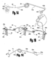
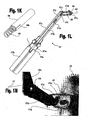
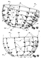
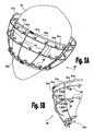
Figs. 1A to 1X schematically illustrate various embodiments of ventricular function assisting devices configured for treating systolic and diastolic dysfunctions and tools suitable for attaching the same to the heart in a minimally invasive procedure, whereinFigs. 1A and 1B show a configuration of anchoring means and elastic elements having G-shaped attachments suitable for use in the ventricular function assisting device,Figs. 1C to 1F show embodiments of anchoring means having dual-level anchoring sites in their head sections and elastic elements having C-shaped attachments,Fig. 1G shows a perspective view of a tool for guiding in the positioning of the attachment means,Fig. 1H shows a perspective view of the attachment means used inFig. 1B ,Figs. 1I to 1N show various views and exemplify the use of a tool for attaching the attachment means of the invention to the wall of the heart,Figs. 10 to 1Q show another embodiment of a tool for attaching the attachment means to the wall of the heart in which the attachment means are maintained in an internal stack,Figs. 1R to 1T shows a tool for delivering and attaching the elastic elements,Fig. 1U shows a perspective view of the ventricular function assisting device of the invention having two operation modes,Fig. 1V shows the ventricular function assisting device shown inFig. 1U when mounted on a heart, andFigs. 1W and 1X illustrate an exemplary implementation of a fastening mechanism (in an open and closed states, respectively) suitable for fastening the ventricular function assisting device over the heart; -
Figs. 2A and 2B schematically illustrate a ventricular function assisting device which employs elastic restrictive elements; -
Figs. 3A and 3B schematically illustrate ventricular function assisting devices for treating systolic and diastolic dysfunctions which employ an intermediate restrictive element; -
Figs. 4A to 4C schematically illustrate an implementation of the ventricular function assisting device which is configured to enclose the apex of the heart, whereinFig. 4A is a perspective view,Fig. 4B schematically illustrates an exemplary fastening mechanism, andFig. 4C is a side view; -
Figs. 5A and 5B schematically illustrate a device for treating systolic and diastolic dysfunctions which is based on a magnetic/electromagnetic mechanism; -
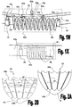
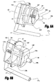
Figs. 6A and 6B schematically illustrate the structure and operation of a ventricular function assisting device of the invention based on an plunger mechanism; -
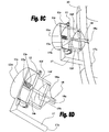
Figs. 7A and 7B respectively show a perspective view and a sectional view of specific implementations of the ventricular function assisting device illustrated inFigs. 6A and 6B . -
Figs. 8A to 8E show sectional views of various implementations of ventricular function assisting devices of the invention based on plunger mechanisms, whereinFig. 8A shows an embodiment employing an anterior spring,Fig. 8B shows an embodiment employing a posterior spring,Fig. 8C exemplifies attachment of an embodiment employing a posterior spring to the heart,Fig. 8D shows an embodiment employing a posterior spring placed in an isolating enclosure, andFig. 8E exemplifies attachment of an embodiment employing an anterior spring to the heart; -
Figs. 9A and 9B schematically illustrate a ventricular function assisting device employing an electromagnetically driven plunger; and -
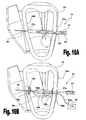
Figs. 10A and 10B schematically illustrate a method and apparatus for inserting treatment devices into the heart and for mounting the same on its inner wall. - It should be noted that the embodiments exemplified in the Figs. are not intended to be in scale and are in diagram form to facilitate ease of understanding and description.
- The present invention provides devices as specified in the appendead claims for treating systolic and/or diastolic heart dysfunctions and delivery tools suitable for delivering and attaching elements to the wall of the heart in a minimally invasive procedure. In general, devices of the present invention are designed to assist the operation of the heart by aiding in volume enlargement of the left ventricle and by reducing the pressures thereinside during diastolic function, and aiding in the pumping of blood from the left ventricle during systolic function. Some embodiments of the invention are further configured to limit ventricular dilatation in the treatment of systolic dysfunctions, wherein the limiting of ventricular dilatation may be activated at a later time after installing the device on a patient's heart (also referred to herein as devices having two operation modes).
- In one preferred embodiment of the invention the ventricular function assisting device is composed of elastic elements designed to be attached to the wall of the left ventricle, and of restrictive elements (e.g., rings or stripes) designed to be fastened over the heart of the patient.
Figs. 1A to 1X illustrate various preferred embodiments of a ventricular function assisting devices comprising elastic (or resilient) elements (43 or 54) having "V"-like shape (e.g., torsion springs), and in some embodiment also restrictive elements, 41a and 41b (shown infigs 1U and 1V ), and tools that may be used for assisting in the attachment of these elements. - In this preferred embodiment ventricular function assisting device (40 shown in
figure 1U and 1V ) is designed to operate in two different modes. In the first mode of operation,device 40 is attached to the patient's heart such thatelastic elements 43 attached over the left ventricle apply tangential and radial forces thereover during contractions and expansions thereof, while the restrictive elements, 41a and 41b, are in a non-operative state, namely, saidrestrictive elements - The first mode of operation of
device 40 is mainly directed for treating diastolic dysfunctions. During the systoleelastic elements 43 are compressed (the distance between their arms is reduced) as they store elastic potential energy. During diastole, the elastic potential energy stored inelastic elements 43 is released as they apply radial and tangential forces over theirrespective attachment elements 45. - In the second mode of operation of
device 40 the perimeter ofrestrictive elements 41 is diminished by means of a fastening mechanism 42 (42a in upperrestrictive element restrictive element 41b) such that saidrestrictive elements device 40 is mainly directed for treating systolic dysfunctions. As will be explained hereinbelow the mode of operation ofdevice 40 may be changed from the first mode to the second mode at a later time, after installing the device. This configuration is particularly desirable in patients initially suffering from diastolic dysfunctions and which develop systolic dysfunction ailments during later treatment stages. -
Figs. 1A and 1B show a configuration of anchoring means 45 andelastic elements 43 suitable for use in the ventricular functions assisting device 40 (shown inFig. 1U and 1V ).Elastic element 43 is preferably a type of torsion spring made from an elastic wire formed in a "V"-like shape, having torsion loop(s) 30 at its apex and "G"-shapedanchoring loops 43a at the end of its arms. Anchoringloops 43a may have a spiral shape and they are preferably formed by bending the end sections of the arms towards spring loop(s) 30, thereby formingknees 43k, and thereafter bending said end sections away from said spring loop(s) 30 to form a spiral shape therewith. In this way an "S"-like shape (marked by dotted line 4 inFig. 1A ) is formed at the end of each arm, wherein the bottom portion of the "S"-like shape is further curved to form the "G"-shapedcurved fasteners 43a. - As best seen in
Fig. 1A ,elastic element 43 comprises afirst arm 14a which is relatively straight, and asecond arm 14b which is curved relative to the plain of the element. As shown inFig. 1B , in the attachment ofelastic elements 43 toattachment elements 45,second arms 14b ofelastic elements 43 are curved such that thestraight arm 14a of the adjacent elastic element may be passed beneath the curved arm to engage the head section of theattachment element 45 while maintaining agap 39 therebetween. - As best seen in
Fig. 1H , anchoring means 45 comprise ahead section 45a, aneck section 45b and anattachment section 45c. Anchoring means 45 are preferably made from a curved wire, wherein theattachment section 45c is curved in a helix (spring) shape ending in a sharp tip for facilitating threading thereof into the wall of the heart. Near theneck section 45b of the anchoring means 45 the distances between the helix loops are reduced abruptly to form theneck section 45b, which acts as a stopper to prevent excess threading of anchoring means 45. - Anchoring means 45 may be used for delivering medicaments into the tissue into which it is threaded. In such implementation the
attachment section 45b of anchoring means 45 may be coated by one or more layers of therapeutic medicaments, or alternatively, theattachment section 45b may be prepared to include an internal lumen, suitable for maintaining said medicaments thereinside, and release aperture communicating with said internal lumen, for releasing the medicaments into the tissue therethrough. These drug delivery implementations may be designed for providing delayed drug delivery to the tissue. - As exemplified in
Fig. 1B , anchoring means 45 may be employed for delivering electrical signal to the heart tissue by connecting apacemaker 85 thereto.Pacemaker 85 is a type of conventional pacemaker device which uses electrical impulses, typically delivered by electrodes contacting the heart muscles, to regulate heart beats. The primary purpose ofpacemaker 85 is to maintain an adequate heart rate, either since the heart's natural pacemaker (the sinus node) is not functioning properly (i.e., slow heart beats), or if there is a block in the heart's electrical conduction system. In some cases it may be advantageous to combine withpacemaker 85 an implantable defibrillators, which is integrated into a single implantable device. Other possible implementations may include multiple electrodes for stimulating different locations over the heart muscle to improve synchronization of the lower chambers of the heart. As shown inFig. 1B , thepacemaker 85 is electrically connected toloop 45a of anchoring means 45 by means ofelectrical cable 85w, wherein anchoring means 45 is implanted in the heart tissue and used as an electrical conductor for delivering the electric signals produced bypacemaker 85 to the heart tissue. - It should be understood that
pacemaker 85 may be implanted together with ventricular function assisting device employing anchoring means 45, or alternatively, it may be implanted later, if required.Pacemaker 85 is implanted in the patient's body in substantially the same way as in conventional pacemaker procedures, such that it may be placed under the chest or abdomen skin of the patient, but instead of using the conventional pacemaker electrodes the electrical signals it produces are delivered to the patient's heart through anchoring means 45. - The
head section 45a is formed in a shape of a loop through which the "G"-shapedanchoring loops 43a of theelastic elements 43 can be passed to engage the same therein.Head section 45a may be formed in any suitable geometrical shape e.g., circular, elliptic, rectangular, however, in this preferred embodiment thehead section 45a is formed in a shape of a ring. - Anchoring means 45 (also shown in
Fig. 1H ) can be threaded into the wall of the heart by rotation. The attachment method ofelastic elements 43 and anchoring means 45 is shown inFig. 1B , wherein twoelastic elements 43 are mounted by means ofattachment elements 45. -
Elastic element 43 may be manufactured using conventional wire (e.g., having circular, elliptic, or rectangular/polygonal cross section) curving techniques, photo chemical etching techniques, laser cutting, or by an erosion process (e.g., using tin films) from a type of elastic metal or plastic, such as, but not limited to, Nitinol, stainless steel, silicon, or a suitable alloy, composite compound, or absolvable material (e.g., PLLA, PGA, or PLA), preferably from a Cobalt alloy, having a diameter (thickness) of about 0.45 mm. The length of the arms ofelastic element 43 may generally be in the range of 20 to 30 mm, preferably about 23 mm, and the angle α therebetween is about 165±5°. The diameter of torsion loop(s) 30 may generally be in the range of 3.5 mm (for elastic elements mounted at the extremities of the lined sequence) to 5.7 mm, and the diameter of the "G"-shapedanchoring loops 43a is preferably about 2±1 mm. - Anchoring means 45 may be manufactured by using conventional spring manufacturing techniques, wire curving processes which may be followed by a suitable thermal treatment to set mechanical characteristics and relax curving tensions. Anchoring means 45 may be manufactured from a type of metal or plastic material, such as, but not limited to, Nitinol, stainless steel, silicon, or a suitable alloy, composite compound, or absolvable material (e.g., PLLA, PGA, or PLA), preferably from, a Cobalt alloy. Most preferably, anchoring means 45 are made from a turned wire having thickness of about 0.45 mm and made of a Cobalt alloy. The total length of anchoring means 45 may generally be in the range of 8 to 18 mm, preferably about 15 mm. The diameter of the helix loops in the
attachment section 45c may generally be in the range of 3 to 6 mm, preferably about 5 mm, the distance between consecutive loops thereof may generally be in the range of 1 to 3 mm, preferably about 2 mm, and the length of said attachment section may generally be in the range of 6 to 12 mm, preferably about 8 mm. The diameter of theneck section 45b may generally be in the range of 2 to 6 mm, preferably about 5 mm, and its length may generally be in the range of 0.5 to 2 mm, preferably about 1.5 mm. - A product comprising elastic elements and anchoring means suitable for ventricular
function assisting device 40 is sold under the ImCardia trademark of CorAssist cardiovascular Ltd., Israel. - Another possible configuration of elastic elements and anchoring means is depicted in
Figs. 1C to 1F . In this preferred embodiment theattachment section 53c and theneck section 53b of the anchoring means 53 are made from a curved wire, while itshead section 53m is made from a flanged rod comprising aflanged base 53g adapted to firmly fit into the loops ofneck section 53b, a flanged top 53h, and amiddle flange 53f therebetween. Thegaps head section 53m betweenflanged base 53g andmiddle flange 53f, and between flanged top 53h andmiddle flange 53f, are adapted to receive "C"-shapedgraspers 54u ofelastic element 54.Elastic element 54 is preferably a type of torsion spring made from an elastic wire formed in a "V"-like shape, having torsion loop(s) 54r at its apex and "C"-shapedgraspers 54u at the end of itsarms 54a. The wire at the tips of "C"-shapedgraspers 43a is preferably shaped to form fastening loops 54q adapted to provide firm attachment over theflanged rod 53m.Flanged rod 53m is preferably attached toneck section 53b of anchoring means 53 by welding. -
Fig. 1F demonstrates attachment of neighboringelastic elements 54 to a mutual anchoring means 69. The attachment section 69c,neck section 69b andhead section 69a, of anchoring means 69 are preferably made from a single wire turned such that the shape ofhead section 69a is similar to the shape of flanged rod (53m) in anchoring means 53, by forming an expanded top 69h and expanded middle 69f such thatcorresponding gaps -
Fig. 1E illustrates one preferred embodiment of an anchoring means 55 havingattachment section 55c andneck section 55b made from a curved wire, and ahead section 55m made from a flanged rod, as in anchoring means 53 (shown inFig. 1D ) described hereinabove, and further comprising domelike top 55z screwed into the flanged top 55h of anchoring means 55 for protecting and preventing tissue injury. In this example elastic elements 54' are attached to anchoring means 55 by means of closed loops provided on its arms and which are fitted into the gaps formed inhead section 55m. Elastic elements 54' and anchoring means 53 may be manufactured from similar materials, and by means of similar techniques, as in the respective means previously described hereinabove. -
Fig. 1G shows a perspective view of a guidingtool 68 suitable for guiding the operator in the positioning of the anchoring means of the invention. Guidingtool 68 comprises anelongated handle 68r and alocator portion 68y attached to its distal end.Locator portion 68y comprises two perpendicular arms used for designating the distance between adjacent anchoring means. In use, the arm having acurved end 68c will typically be engaged in the attachment section of the anchoring means (e.g., 45c of anchoring means 45) while the arm comprising thevertical ending 68u will be used to guide the operator in determining a location for a new anchoring means to be attached. Guidingtool 68 may be manufactured from stainless steel, nitinol, or from a biocompatible alloy, by extrusion or a metal working process, for example. The length of guidingtool 68 may generally be in the range of 180-200 mm, its diameter about 1 to 2 mm, and the width oflocator portion 68y may be about 30 to 70 mm. -
Figs. 1H to 1O illustrate and demonstrate attachment of the anchoring means 45 depicted inFig. 1H by means of a screwingtool 57. With reference toFig. 1J , screwingtool 57 comprises aproximal handle 57h to which there is attached ahollow shaft 57s having a hingedhead 57d connected thereto byhinge 57i.Proximal handle 57h comprises arotatable wheel 57w mounted indepressions 57e provided in opposing sides ofproximal handle 57h. Screwingtool 57 may further comprise afoldable locator 57g for aiding the operator in determining locations for screwing the anchoring means 45 over the heart wall. InFig. 1J foldable locator 57g is shown in its deployed state, if however it is not needed, it may be rotated about the hinges connecting it to hingedhead 57d, such that it is placed over and aligned with a side surface thereof. - With reference to
Fig. 1L , illustrating a sectional view of screwingtool 57, hingedhead 57d comprises a distal opening 57o adapted to receive and hold a holdingcup 56 in which anchoring means 45 is held by means of afastening rod 58. The base of holdingcup 56 is firmly received inrotatable holder 57z rotatably mounted inside hingedhead 57d, on its base.Hollow shaft 57s comprises arotatable rod 57q placed thereinside mechanically linked torotatable wheel 57w. At the distal end ofrotatable rod 57q there is attached one end of a wire (or flexible rod) 57r, which other end is attached torotatable holder 57z provided inside hingedhead 57d. In this way rotary motion ofwheel 57w is delivered viarod 57q andwire 57w torotatable holder 57z, which in turn delivers the rotary motion to thefastening rod 58 and anchoring means 45 assembly held by holdingcup 56. -
Fig. 1K shows a perspective view offastening rod 58 having an anchoring means 45 attached to it. As shown,fastening rod 58 comprises acentral slit 58s passing along a longitudinal section of its length. Central slit 58s is adapted to receive and firmly hold the head section (45a) of anchoring means 45.Fig. 1I shows a perspective view of holdingcup 56 holding a fastening rod 58 (not shown) and anchoring means 45 assembly, wherein it is seen that holdingcup 56 is made from a generally acylindrical element 56c havingflanged edge 56f over itsopening 56p, which is adapted to receive saidfastening rod 58 and anchoring means 45 assembly. -
Figs. 1M and1N , are exemplifying attachment of anchoring means by means of screwingtool 57. During this process the operator adjusts the angle of hingedhead 57d to allow its front side to face and access theheart 10, and then the anchoringwindow 57n oflocator 57g is placed over a previously placed anchoring means 45, thus providing a tolerance for determining a suitable location for attaching the new anchoring means. Once the new location is determined the operator gently presses the front side of hingedhead 57d of screwingtool 57 against the wall of theheart 10 and rotateswheel 57w, thereby screwing anchoring means 45 into the tissue. - Screwing
tool 57 may be manufactured from stainless steel, Teflon, nitinol, polycarbonate, silicon, medical grade delrin, medical grade nylon, or from a biocompatible alloy, by means of extrusion, rapid prototyping, or metal working, for example. The length of screwingtool 57 may generally be about 200-500 mm and its diameter about 10-40 mm. -
Figs. 1O to 1Q illustrate a preferred embodiment of atool 60 designed for delivering and attaching several anchoring means 45 stacked in series inside itshollow shaft 60s configured as a stack having alongitudinal slit 60i along its length adapted to slidably hold the head sections (45a) of anchoring means 45. The anchoring means 45 are pushed distally byspring 60p and the most distal anchoring means 45 stacked insideshaft 60s is attached to a screwinghead 60t configured to hold thehead section 45a of the anchoring means 45 and rotate it when push-button 60d inproximal handle 60h is pressed by the operator. Whenever pressed down, push-button 60d activates an electrical motor (not shown) configured to deliver rotational motion to screwinghead 60t. - As seen in
Fig. 1O ,tool 60 further comprises amovable rod 60a passing along the length of its bottom side, saidmovable rod 60a is mechanically linked toslider 60r. With reference toFig. 1Q , showing a top view of the proximal section oftool 60,slider 60a may be changed between two operation states, by retaining it inlateral slit 60q or inlateral slit 60r. Locator 60W is placed over a previously placed anchoring means 45, thus providing an anchor for determining a suitable location for attaching the new anchoring means. Once the new location is determined the operator gently push themovable rod 60a into the lateral slit 60q and push-button 60d inproximal handle 60h to operate thedelivery tool 60 for implantation a new anchoring means 45. - As seen in
Fig. 1O , the distal part ofhollow shaft 60s may comprise optical guiding means 60g mounted on opposing sides thereof and adapted to emit light beams (e.g., by means of low-energy laser diodes) set in proper angles such that one light beam can point to a new location for placing a new anchoring means whenever the other light beam is placed over the location of a previously placed anchoring means, thereby aiding the operator in determining a proper distance between the anchoring means. - It is noted that the
delivery tools Fig. 1F ), anchoring means 53 (shown inFig. 1D ), described hereinabove, and modifications thereof. -
Figs. 1R to 1T show various views of adelivery tool 59 designed for delivering an elastic element 43 (or other such elastic elements, such as for example, 43 shown inFig. 1A , 54 shown inFig. 1C , or 54' shown inFig. 1E ) and attaching the same over previously placed anchoring means in a minimally invasive procedure. With reference toFig. 1R ,delivery tool 59 comprises ahollow handle 59h having alongitudinal slit 59s passing along a portion of its length in which there is movably placed aslider element 59p, aslidable shaft 59f extending distally therefrom and which proximal portion is placed insidehollow handle 59h and mechanically linked toslider element 59p by means ofslidable connector 59c, and alongitudinal rod 59r fixedly attached to handle 59h at 59n and passing inside, and along the entire lengths of,hollow handle 59h andslidable shaft 59f. The distal end oflongitudinal rod 59r comprises a retainingpart 59k configured to receive and hold the torsion loop(s) (30) of the elastic element. - As seen in
fig. 1R longitudinal slit 59s comprises aproximal recess 59b and adistal recess 59y in each of which slider element may be placed. In a first state ofdevice 59, shown inFigs. 1R to 1T ,slider element 59p is held inproximal recess 59b, in whichstate slidable shaft 59f is pulled proximally such that retainingpart 59k is exposed through distal end opening ofslidable shaft 59f. In a second state of device 59 (not shown)slider element 59p is held indistal recess 59y, in whichstate slidable shaft 59f is pushed distally such thatslidable shaft 59f is pushed distally and retainingpart 59k is introduced intochamber 59g provided insideslidable shaft 59f at its distal end. - In
Fig. 1T there is shown an enlarged view of the distal portion ofdelivery tool 59 when anelastic element 43 is retained in its retainingpart 59k. As seen, retainingpart 59k comprises offlat section 59e on which there is a holdingshoulder 59y which upper protrusion is facingslidable sheath 59f, and atooth 59x formed at its distal end. The distance betweenshoulder 59y andtooth 59x is configured such that torsion loop(s) 30 of theelastic element 43 are retained thereover by placing apex of the "V"-shapedelastic element 43 under the upper protrusion ofshoulder 59y and the opposing side of torsion loop(s) 30 overtooth 59x. In this way, when slider element is placed indistal recess 59yslidable shaft 59f is pushed over retainingpart 59k andelastic element 43 held by it; such thatarms elastic element 43 are bent distally intochamber 59g. - In this way the
elastic element 43 is delivered in a folded state (not shown) through a small incision and attached to the anchoring means previously placed on the heart by placing the distal end oftool 59 near the previously attached anchoring means and movingslider element 59p back toproximal recess 59b, which in turn retractsslidable shaft 59f proximally and exposes elastic element out ofchamber 59g. The operator then simplymaneuvers tool 59 andslider element 59p for properly engaging "G"-shapedanchoring loops 43a of elastic element 43 (or C-shapedgraspers 54u of elastic element 54) inhead sections 45a of anchoring means 45, as illustrated inFig. 1B . -
Delivery tool 59 may be manufactured from stainless steel, Teflon, nitinol, polycarbonate, silicon, medical grade delrin, medical grade nylon, or from a biocompatible alloy, by means of extrusion, rapid prototyping, or metal working, for example. The length ofdelivery tool 59 may generally be about 200-500 mm and its diameter about 10-40 mm. -
Fig. 1U shows a perspective view of one preferred embodiment of ventricularfunction assisting device 40.Device 40 is configured to encircle the heart 10 (shown inFig. 1V ) by at least two, upper and lower, restrictive elements, 41a and 41b, respectively. The upper and lower restrictive elements, 41a and 41b, are connected by means ofsprings 46 to a set ofvertical bars 47 equally distributed about the perimeters ofrestrictive elements Springs 46 may be pulling and/or pushing springs and they are mainly used whendevice 40 is operated in the second mode of operation i.e., after restrictive elements, 41a and 41b, are secured to the wall of the heart by means of fastening mechanisms, 42a and 42b, respectively.Vertical bars 47 are preferably curved according to the curvature of the heart, but the may also be flexible enough to allow them to easily curve and assume a curvature more or less similar to the curvature of the heart. -
Vertical bars 47 are attached to the wall of the heart by means of anchoring means 45 threaded into the wall of theheart 10 along their lengths.Vertical bars 47 are passed through the head sections (45a) of anchoring means 45, such that minimal or negligibly small forces are applied over the wall of the heart byvertical bars 47 at the attachment points of anchoring means 45 whendevice 40 is operated in the first mode of operation. - The portion of
device 40 mounted over the left ventricle further compriseselastic elements 43 which are mounted more or less horizontally between pairs of adjacent anchoring means 45 attached to the wall of ventricle. Restrictive elements, 41a and 41b, comprises a fastening mechanisms, 42a and 42b, respectively, which are initially in a state which allows encircling the heart byrestrictive elements restrictive elements Fastening mechanisms heart 10 at a later time after the mounting procedure ofdevice 40 on the heart is completed. - In this way the operation of
device 40 may be changed into its second mode of operation whenever needed, particularly if the patient develops systolic dysfunctions. The activation of fastening mechanisms, 42a and 42b, may be carried out by a minimally invasive procedure, for example, via a small incision, by connecting access tubes todevice 40 each having one opening near fastening mechanism (e.g., 42a) and another opening being externally accessible by the practitioner such that suitable instruments (e.g., clamps, tweezers) may be introduced therethrough for fastening restrictive elements over the heart. -
Fig. 1V show the ventricularfunction assisting device 40 illustrated inFig. 1U , when mounted on aheart 10.Fig. 1W illustrates a possible implementation of alocking mechanism 42a (or 42b) suitable for fastening the ventricularfunction assisting device 40 over theheart 10. In this implementation a pullingspring 50 is mounted over agap 41g inrestrictive element 41a. Pullingspring 50 may be mounted by means of twosocket members 51 formed, or attached, onrestrictive element 41a neargap 41g, and havingrespective sockets 51s capable of receiving spring ends 50e and securing the same torestrictive element 41a. -
Locking mechanism 42a further comprises a supportingbar 52 configured to attach torestrictive element 41a over the opening ofgap 41g. In thisway gap 41g is maintained inrestrictive element 41a due to supportingbar 52, which prevents its closure by pullingspring 50. Supportingbar 52 comprises attachment pins 52b provided at its ends, said attachment pins 52b are more or less perpendicular to supportingbar 52 for allowing them to be received inrespective sockets 41s provided in the opposing sides ofrestrictive element 41a, havinggap 41g there between.Grip 52g is attached, or formed, perpendicular to supportingbar 52 more or less about its center, for providing the practitioner a convenient grip for removing supportingbar 52 when the fastening ofrestrictive element 41a overheart 10 by the closure ofgap 41g is needed, as shown inFig. 1X . Conveniently,grip 52g may include ahead portion 52h for improving the grip there over. -
Restrictive elements 41 may be manufactured from a biocompatible metallic alloy, for example, from stainless steel or from a biocompatible polymer, for example silicon, preferably from stainless steel. The lengths ofrestrictive elements 41 should be adjusted according to the size of the treated heart, for example, the length of upperrestrictive element 41a may generally be in the range of 115 to 145 mm, preferably about 125 mm, and the length of lowerrestrictive elements 41b may generally be in the range of 10 to 120 mm, preferably about 50 mm. -
Vertical bars 47 may be manufactured from a biocompatible metallic alloy, for example stainless steel or Conichrome (fwm 1058) or from a biocompatible polymer, for example silicon, preferably from stainless steel. The lengths ofvertical bars 47 may generally be in the range of 70 to 120 mm, preferably about 90 mm.Springs 46 are preferably small springs made from a biocompatible metal alloy, for example stainless steel or Conichrome (fwm 1058), configured to apply forces in the range of 0.7 to 1.2 N. - Referring now to
figure 1W , Pullingspring 50 is preferably made from an elastic wire having a diameter generally in the range of 0.3 to 0.7 mm, preferably about 0.5 mm, and it is preferably made flat (e.g., having elliptic or rectangular spring loops) in its cross-sectional profile.Spring 50 may be manufactured by conventional spring manufacture techniques, from a type of biocompatible metallic alloy, for example stainless steel or Conichrome (fwm 1058), preferably from Conichrome. The length ofspring 50 may generally be in the range of 10 to 20 mm, preferably about 15 mm. -
Gap 41g may generally be in the range of 5 to 20 mm, preferably about 10 mm. Supportingbar 52 may be manufactured from a biocompatible metallic alloy, for example stainless steel or Conichrome (fwm 1058), preferably from Conichrome. The diameter of supportingbar 52 may generally be in the range of 1 to 3 mm, preferably about 2 mm, and its length should be fitted to the length ofgap 41g. - Ventricular
function assisting device 40 may be mounted on the heart of a treated subject in a procedure comprising the following steps: first in open chest surgery followed by thoracotomy, and at a later stage, when the systolic device needs to be functional, this may be performed utilizing minimal invasive thoracoscopy procedure. Normally,device 40 will be installed in its first mode of operation for treating diastolic dysfunctions. If at a later time the patient develops systolic dysfunction ailments the state of the device may be changed to operate in its second mode of operation by fasteningrestrictive elements 41 over the heart. The fastening ofrestrictive elements 41 may be carried out as follows: pull out thepin 52 by minimal invasive procedure and thereby causingrestrictive elements 41 to fasten over the heart automatically. - Of course,
device 40 may be installed on the heart of a treated subject initially in its second mode of operation, if treatment of both, diastolic and systolic dysfunctions is required. - In the example illustrated in
Figs. 1C and1D , only two restrictive elements (41a and 41b) are shown, however, it should be clear that embodiments of the invention may include more than two such elements. -
Figs. 2A and 2B schematically illustrate an embodiment of the ventricularfunction assisting device 61 for treating systolic and diastolic dysfunctions, in which therestrictive elements Fig. 2A shows the side ofdevice 61 which is installed over the right ventricle andFig. 2B shows the other side of the device, which is installed over the left ventricle of the heart. In this embodimentvertical bars 47 may be connected directly to tension springs 65a and 65b, or by means of springs (not shown), as exemplified inFigs. 1C and1D . -
Device 61 may be installed on the wall of the heart of a treated subject by means of anchoring means 45, as exemplified inFigs. 1A to 1D , and can partially or completely circumvent the heart. Preferably, the operation ofdevice 61 may be changed between two operation modes by means of fastening mechanisms (e.g., 42a demonstrated infigs. 1W and 1X ) provided in its restrictive elements. 65a and 65b (not shown), as exemplified hereinabove. - Alternatively, the embodiment shown in
Figs. 2A and 2B the ventricularfunction assisting devices 61 may be operated in only one mode of operation, in which both diastolic and systolic dysfunctions are treated. Namely, afterdevice 61 is installed on the wall of the heart of the patient, the operations of both theelastic elements 43 and of therestrictive elements 65a are effective. -
Figs. 3A and 3B schematically illustrate ventricular function assisting devices, 63 and 64, respectively, for treating systolic and diastolic dysfunctions, which employ intermediate restrictive elements, 65c and 41c, respectively. In these embodiments shortervertical bars 47s are used for connecting between the restrictive elements. For example, inFig. 3A ,vertical bars 47s are used for connecting upperrestrictive element 65a to intermediaterestrictive element 65c, and for connecting lowerrestrictive element 65b to intermediaterestrictive element 65c. As previously explained, any number of such restrictive elements may be used, and the number of elements shown inFigs. 3A and 3B is provided by way of example only. -
Vertical bars 47s may be connected to the restrictive elements by means ofsprings 46s. Furthermore, the lengths ofvertical bars 47s connecting between the upper restrictive element (e.g., 41a) and the intermediate restrictive element (41c) may be different from the lengths ofvertical bars 47s connecting between the lower restrictive element (e.g., 41b) and the intermediate restrictive element (41c). - In the
device 63 shown inFig. 3A restrictive elements 65 have a wavy configuration for increasing their elasticity.Restrictive elements Figs. 2A and 2B ,device 63 may be operated in only the second mode of operation, in which both diastolic and systolic dysfunctions are treated.Device 63 may be similarly attached to the wall of the heart by means of anchoring means (45 not shown). - The
device 64 shown inFig. 3B is principally similar to the device shown inFigs. 2A to 2D , where the main differences are in the use of intermediaterestrictive element 41c, and connecting the same torestrictive elements vertical bars 47s. -
Figs. 4A to 4C schematically illustrates an implementation of a ventricularfunction assisting device 77 for treating combined systolic and diastolic dysfunctions which is configured to enclose the apex of theheart 10. As illustrated in the perspective view shown inFig. 4A ,device 77 comprises a singlerestrictive element 41, and as more clearly seen in the side view shown inFig. 4C ,vertical bars 47 are forming aclosed connection point 48 at the bottom of device 77 (e.g., by means of cylinder pivot or a kind of joint). -
Fig. 4B schematically illustrates a possible fastening mechanism based on threading. In this example, the fastening mechanism is based on a simple screw tightening method (e.g., gear clamp), whereinscrew 42t is used for tightening (or for loosening)restrictive element 41 aboutheart 10. This mechanism may be manufactured from biocompatible materials similar to those discussed hereinabove, preferably from stainless steel, employing conventional standard manufacture techniques. -
Figs. 5A and 5B schematically illustrate adevice 80 for treating systolic and diastolic dysfunctions which is based on a magnetic mechanism.Device 80 comprises an upperrestrictive element 41a and a lowerrestrictive element 41b which are connected by means of curvedvertical bars 47.Vertical bars 47 provide a support for a set of one or morehorizontal rings 49 encirclingheart 10. Eachhorizontal ring 49 comprises a set ofelectromagnets 81a, each of which is connected to a controllable power source (e.g., current source, piezoelectric, not shown). A corresponding set ofpermanent magnets 81b is attached to the wall of theheart 10 opposite toelectromagnets 81a, such that pairs ofadjacent electromagnets 81a andpermanent magnets 81b are obtained. - As exemplified in
Fig. 5B , which shows a portion ofdevice 80 withoutheart 10,permanent magnets 81b may be attached to the wall of theheart 10 by means of anchoring means 45, or by a modification or any of the various variations thereof exemplified hereinabove, adjusted to include apermanent magnet 81b at their head section (45a not shown). Control means (not shown) is used to control the operation of the power source used for energizing electromagnets 81. In cases of systolic dysfunctions, during systole, the control means operates the power source to activateelectromagnets 81a such that the polarity of the magnetic field produced thereby causes repulsion forces to evolve betweenelectromagnets 81a andpermanent magnets 81b, in order to assist the systolic heart contraction. In cases of diastolic dysfunctions, during diastole, the control means operates the power source to activateelectromagnets 81a such that the polarity of the magnetic field produced thereby causes attraction forces to evolve betweenelectromagnets 81a andpermanent magnets 81b, and thereby assist in the diastolic heart expansion. - Of course, the operation of the electromagnets should be synchronized with the heart activity. The synchronization may be achieved by monitoring ECG signal, signals received from a pacemaker, or by means of a suitable internal sensor. Horizontal rings 49 may be manufactured from the same material of
vertical bars 47, and they may be attached to saidvertical bars 47 by a rigid or non-rigid connection. The pairs ofelectromagnets 81a andpermanent magnets 81b are adapted to produce repulsion/attraction forces generally in the range of 0.7 to 1.2 N.Permanent magnets 81b may be manufactured from a magnet with biocompatible cover.Electromagnets 81a may be implemented by small coils having a core made from a paramagnetic or ferromagnetic material (e.g., magnesium, molybdenum, lithium, or tantalum); said coils may be manufactured from copper. The distances betweenelectromagnets 81a andpermanent magnets 81b may generally be in the range of 0 to 10 mm. - In another example the ventricular function assisting device is based on a plunger mechanism designed to - i) augment the relaxation of the left ventricle of the heart during diastolic phase, which assists in reducing the pressure thereinside and in pumping blood thereinto; and ii) help the left ventricle during systolic function, to pump out the blood from said ventricle.
- The plunger mechanism device generally consists of two hollow sections, a front section and a rear section, which interiors are communicated by a mutual opening, wherein said hollow sections comprise mechanically linked slidable plungers installed in each of said sections. The hollow sections and their respective plungers are aligned along a longitudinal axis of the device (also referred to as axis of movement) such that said plungers are free to move thereinside along said longitudinal axis. The plungers are mechanically linked to an elastic or shape memory device, preferably in a form of a spring, which is adapted for applying mechanical forces on said plungers for sliding the same in their respective sections.
- The front and rear hollow sections of the device are designed to communicate with a chamber of the heart and to pump in, and pump out, volumes of blood from/to said chamber. The front hollow section of the device comprises a front opening, preferably aligned with the axis of movement of the plungers, adapted to communicate with a chamber of the heart via a first aperture in the wall of the heart. The rear hollow section of the device comprises a lateral opening which is adapted to communicate with the chamber of the heart via a tube, said tube being connected to said lateral opening at one end thereof and to a second aperture in the wall of the heart by another end thereof.
- The plungers may be mechanically linked by a rod connecting between the centers of said plungers. The surface areas of the plungers are designed such that different forces are applied thereover responsive to the pressure in the chamber of the heart to which the device is connected. More particularly, the surface area of the plunger installed in the front hollow section is configured to be smaller than the surface area of the plunger installed in the rear hollow section of the device, and the cross sectional area of said hollow sections is configured correspondingly to snugly fit over said plungers. The elastic/shape memory device is adapted to apply mechanical forces over the plunger's assembly (the plungers and the rod connecting them) for pushing the same towards the rear section of the device.
- The different surface areas of the plungers and the forces applied by the elastic/shape memory device are designed such that during diastolic function the forces applied over the front plunger by the blood pressure in the chamber of the heart and by the elastic/shape memory (pushing spring) device force the plungers assembly to move towards the rear section of the device, thereby increasing the volume of the heart chamber, assisting in pumping blood thereinto, and reducing the pressure thereinside. During the systole function, due to the increased blood pressure, the forces applied over the rear plunger are greater than the forces applied over the front plunger by the blood pressure and the elastic/shape memory (pushing spring) device, such that the plungers assembly is forced to move toward the front section of the device, thereby reducing the volume of the heart chamber and assisting in pumping out blood therefrom.
-
Figs. 6A and 6B schematically illustrate the structure and operation of one preferred embodiment of a ventricularfunction assisting device 12 based on a plunger mechanism. Ventricularfunction assisting device 12 comprises a fronthollow section 12f and a rearhollow section 12r having amutual opening 12m connecting their interiors.Front plunger 14f is slidably installed inside fronthollow section 12f, andrear plunger 14r is slidably installed inside rearhollow section 12r.Rod 15 is used for connecting the center offront plunger 14f to the center of therear plunger 14r. - Front
hollow section 12f of thedevice 12 comprises a front opening 12o adapted to communicate with the interior of theheart 10 via afirst aperture 10b formed inheart 10.Support 19, preferably implemented by a rod, is mounted in front opening 12o to provide a support for spring 13 (pushing spring) mounted thereon, such thatspring 13 is capable of applying mechanical forces overfront plunger 14f along alongitudinal axis 6 ofdevice 12.Tube 17 communicates with the interior of rearhollow section 12r via alateral opening 121 provided in saidrear section 12r.Tube 17 comprises an angled or curved section which more or less aligns opening 17o oftube 17 with opening 12o of fronthollow section 12f. Opening 17o is adapted to communicate with the interior ofheart 10 via asecond aperture 10a formed in the wall ofheart 10. - In one specific example (not shown) the pressure changes in
heart 10 are affected inside ventricularfunction assisting device 12 viatube 17 by means of intermediate means, such that blood is not flown through the entire length oftube 17. In one possible implementation pressure sensors are used for measuring the pressure in theopenings function assisting device 12 is adjusted accordingly. Alternatively, pressure changes may be affected in ventricularfunction assisting device 12 by fillingtube 17 with a type of biological fluid (non compressible) capable of transferring the pressure changes intodevice 12. In yet another implementation, springs and plunger assembly may be used to transfer the pressure fromlateral opening 121 tosecond aperture 10a. - The front and rear plungers, 14f and 14r, are designed such that different powers are applied there over by the blood pumped in and out of
heart 10. For this purpose the surface area (Af, e.g., 78 to 710 mm2) offront plunger 14f is made smaller relative to the surface area (Ar, e.g., 78 to 710 mm2) ofrear plunger 14r.Spring 13 is configured to apply forces (e.g., Fx, e.g., 1 to 10 N) overfront plunger 14f which enables the plungers assembly to slide alonglongitudinal axis 6 responsive to pressure variations in heart chamber to which the device is connected. -
Fig. 6A illustrates the operation of thedevice 12 during the diastole, in which the pressure in the heart chamber is reduced such that the sum of forces applied over thefront plunger 14f due to the diastolic pressure (Pd) in the heart chamber (Ps·Af) and by spring 13 (Fx), is greater than the force applied overrear plunger 12r due to said diastolic pressure (Pd) i.e., Pd·Af + Fx > Pd·Ar. In response, the plungers' assembly (i.e.,front plunger 14f,rear plunger 14r, androd 15 connecting them) is forced to slide towardsrear section 12r ofdevice 12. As demonstrated byarrows 8i the rearward movement of the plungers assembly increases the chamber volume and assists in pumping blood thereinto. In response, portion of the blood indevice 12 is discharged intoheart 10, as demonstrated by arrows 7o. -
Fig. 6B illustrates the operation of thedevice 12 during the systole, in which the pressure in the heart chamber is increased such that the sum of forces applied over thefront plunger 14f due to the systolic pressure (Ps) in the chamber (Ps·Sf) and by spring 13 (Fx), is smaller than the force applied overrear plunger 14r due to said systolic pressure (Ps) i.e., Ps·Af + Fx < Ps·Ar. In response, the plunger assembly is forced to slide towardsfront section 12f ofdevice 12. As demonstrated by arrows 8o, this movement offront plunger 14f assists in pumping out blood from the ventricle. In response, a volume of blood is pumped intodevice 12 viatube 17, as demonstrated byarrows 7i. -
Fig. 7A shows a perspective view of a ventricularfunction assisting device 12, as illustrated inFigs. 6A and 6B , wherein thefront section 12f and therear section 12r are implemented by two sealably connected hollow bodies. In this embodiment spring 13 (not shown) is mounted on asmall disk 9 provided on supports 19.Fig. 7B is a longitudinal-section view illustrating an embodiment wherein pullingspring 13a is used, said pullingspring 13a is mounted in aspring enclosure 13e provided betweenrear plunger 14r and arear wall 12w ofrear section 12r.Spring 13a is sealably enclosed inspring enclosure 13e to prevent the blood moving indevice 12 from contacting the spring. -
Fig. 8A is a longitudinal-section view of an embodiment of the diastolic function assisting device of the invention wherein the interior of thefront section 12f communicates with the interior of the heart via ashort tube 18. In thisembodiment front section 12f comprises afront wall 18w used for closing the front side offront section 12f, wherein saidfront wall 18w has a tapering shape and comprises an opening (not shown) adapted to communicate withtube 18.Tube 18 andwall 18w are adapted to be attached to the wall of theheart 10, as illustrated inFig. 8E . In this configuration Blood may be flown via an opening 18o oftube 18, into, or out from,device 12.Fig. 8E is a longitudinal section view of the embodiment shown inFig. 8A showing said device mounted on the wall of theheart 10. -
Fig. 8B is a longitudinal-section view illustrating an embodiment ofdevice 12 configured to be connected to the wall of theheart 10 by means offront wall 18w andtube 18, as inFig. 8A , wherein pullingspring 13a is used, said pullingspring 13a is mounted betweenrear plunger 14r andrear wall 12w ofrear section 12r.Fig. 8C illustrates a longitudinal section view of this embodiment when mounted on a wall ofheart 10. -
Fig. 8D is a longitudinal-section view of an embodiment ofdevice 12 configured to be connected to the wall of theheart 10 by means offront wall 18w andtube 18, as inFig. 8A , wherein pullingspring 13a is mounted in aspring enclosure 13e betweenrear plunger 14r andrear wall 12w ofrear section 12r.Spring enclosure 13e may be a type flexible tube made of silicon, polyurethane, or any kind of flexible polymer, suitable for sealingspring 13a and preventing blood from contacting it. - Ventricular
function assisting device 12 may be manufactured, for example, by machining or injection, from type of biocompatible materials, such as for example, stainless steel, cobalt alloy, silicon, or Teflon, preferably from stainless steel. Spring 13 (or pullingspring 13a) may be manufactured from a suitable type of elastic or shape memory material, such as, but not limited to biocompatible metal alloy, preferably from stainless steel. The length ofspring 13, or of pullingspring 13a, may generally be in the range of 5 to 25 mm, preferably about 15 mm, and its diameter may generally be about 0.1 to 1 mm. - Front
hollow section 12f is preferably made from a cylindrical body having a diameter generally in the range of 10 to 30 mm and a length generally in the range of 5 to 25 mm. Rearhollow section 12r is preferably also made from a cylindrical body having a diameter generally in the range of 15 to 45 mm and a length generally in the range of 5 to 25 mm. Front and rear sections may be manufactured as integral parts ofdevice 12, or alternatively, as separate parts which may be connected, for example, by means of screws. -
Tube 17 is preferably manufactured as an integral part ofrear section 12r, and it may be manufactured from the same material said rear section is made from. Similarly,tube 18 andfront wall 18w are preferably manufactured as integral parts offront section 12f, and they are made from the same material from which said front section is made. - Front and rear plungers, 14f and 14r, may be implemented by bodies having a disk shape made from stainless steel or silicon, preferably from silicon, adapted to be slidably installed in front and rear hollow sections, 12f and 12r, respectively.
-
Figs. 9A and 9B schematically illustrate a ventricularfunction assisting device 90 employing an electromagnetically drivenplunger 93.Device 90 is preferably made from a hollow cylindrical body which interior may be accessed viabore 90p provided in itsfront wall 90t.Front wall 90t may be advantageously formed in a conical shape having aflare 90f at its tip for assisting in mounting it in the wall ofheart 10. Said mounting of ventricularfunction assisting device 90 is preferably carried out by forming asmall incision 10a in the wall of the heart and introducing the flaringfront end 90f ofdevice 90 thereinto such that theopening 90a ofbore 90p communicates with an interior of a heart chamber.Device 90 may be secured in its mounted state to theheart 10 by means of pressure, tightening or suturing. Volumes of blood may thus be injected/ discharged into/fromdevice 90. - With reference to
Fig. 9B , ventricularfunction assisting device 90 further comprises anelectromagnetic plunger 93, and afirst coil 91a, winded over (or inside) a rear section of cylindrical body ofdevice 90, and asecond coil 91b wound over (or inside) a front section ofdevice 90 near itsfront wall 90t, said coils are adapted to receive electrical currents and apply opposing magnetic fields generally perpendicular to the plane ofmagnetic plunger 93, such that said electromagnets may be activated alternately to apply back and forth driving forces overmagnetic plunger 93. - More particularly, during the diastole
second coil 91b is activated to apply axial forces overplunger 93 for sliding it towards the rear side of device 90 (i.e., by applying magnetic repulsion forces) and thereby pump a volume of blood (e.g., about 10-200 ml) thereinto and assist in reducing the pressure inheart 10 and in pumping blood into it. The rearward movement ofplunger 93 may be limited by astopper 90s formed in, or attached on, a rear section of the internal wall ofdevice 90. During the systole, thefirst coil 91a is activated to apply axial forces overplunger 93 for sliding it towards the front side of device 90 (i.e., by applying magnetic attraction forces) and thereby discharge a volume of blood therefrom and assist in increasing the pressure inheart 10 and in pumping blood therefrom. - Ventricular
function assisting device 90 may be manufactured from a type of biocompatible metalic material, for example stainless steel, or alternatively from a type of biocompatible polimer, preferably from stainless steel, its diameter may generally be in the range of 10 to 60 mm, preferably about 25 mm, and its length may generally be in the range of 10 to 40 mm, preferably about 30 mm. The volume ofdevice 90 may generally be in the range of 10 to 200 ml, preferably about 50 ml. Coils 91 are preferably made from an electrically conducting wire made from copper the diameter of the wires and the number of turns are preferably adjusted for generating a magnetic filed in the range of 0.000001 to 0.1 Tesla responsive to electrical currents in the range of 0.0001 to 10 amperes. - The electrical current may be supplied to coils 91 by an implantable battery (not shown). The operation of coils 91 may be activated by an implantable control logic and/or programmable controller (not shown), employing ECG sensing means (or pacemaker) for synchronizing device operation with the heart function.
-
Magnetic plunger 93 is a permanent magnet made from a type of magnetic material, such as for example stainless steel, its thickness may generally be in range of 0.5 to 3 mm, and its diameter is adjusted to allow it to smoothly slide insidedevice 90 along its length. The magnetic strength ofmagnetic plunger 93 may generally be in the range of 0.001 to 1000 gauss. - Ventricular
function assisting device 90 may be connected to the heart in a minimal invasive procedure via a small opening formed in the patient's chest. The device may be connected to the tissue of the left ventricle by suturing, insertion under pressure and/or threading it into the tissue. -
Device 12 may be installed on the wall of the heart of a patient in a procedure comprising the following steps: open chest surgery, thoracotomy, or minimal invasive thoracoscopy.Apertures heart 10 by a surgical cutting device or by a needle, anddevice 12 may be attached to the wall of theheart 10 by pressure, surgical sutures, stapling devices or adhesives. -
Figs. 10A and 10B schematically illustrate a method anddevice 95 for deliveringtreatment device 100 into theheart 10 and for mounting the same on its inner wall.Delivery tool 95 generally comprises atube 97 and aguide wire 99 passing there inside. At the first step of an insertion procedure theguide wire 99 is inserted at the desired location to mark the device implantation trajectory. Thedevice 100 can be placed at different locations, e.g., between the lateral wall to the septum, or between the anterior to the posterior walls.Tube 97 is introduced intoheart 10 overguide wire 99 via asmall incision 10i formed in thefree wall 10w of theheart 10, such thatopening 97a oftube 97 is placed more or less in front of thedistal wall 10d. - In this state a device 100 (e.g., bent spring) may be installed inside
heart 10. The device to be installed is advanced throughtube 97 and it may be installed by performing the following steps: advancing a portion ofdevice 100 such that a firstexpandable element 98a ofdevice 100 is released throughopening 97a, the state of said firstexpandable element 98a is then changed into an open (deployed) state and pressed against thedistal wall 10d ofheart 10 by distal anchoring means 98c (e.g., bars, screw, hook); retractingtube 97 proximally such that a secondexpandable element 98b is released viaopening 97a, said secondexpandable element 98b is then changed into its deployed state and pressed against theproximal wall 10w ofheart 10 by wall anchoring means 98d (e.g., bars, screw, hook) astube 97 is withdrawn fromheart 10 viaincision 10i. -
Tube 97 may be manufactured from Nylon, Silicon, Teflon, or any kind of suitable polymer, preferably from Teflon, and its diameter may generally be about 2 to 10 mm. -
Device 100 may be used for applying forces overheart walls distal anchoring 98c may be used as electrical connecting means for delivering electrical signals produced bypacemaker 85. Whenpacemaker 85 is attached to the wall anchoring 98d anddistal anchoring 98c that is implanted in the heart tissue and used to conduct the electric signal frompacemaker 85 viaelectrical cables 85w to heart tissue and to pace the left ventricle, or the right ventricle, or both of them. -
Expandable elements tube 97 and open laterally when it is released therefrom.Expandable elements -
Distal anchoring 98c and wall anchoring 98d may be manufactured from nitinol or Conichrome (fwm 1058), for example, in shape of short tubes having a length of about 3 to 20 mm and inner diameter of about 1 to 10 mm.Distal anchoring 98c and wall anchoring 98d are preferably connected to the centers ofexpandable elements guide wire 99.Distal anchoring 98c and wall anchoring 98d are configured to be introduced into the wall of the heart for attachingtreatment device 100. This is preferably achieved by screwing or sticking. -
Pacemaker 85 can be implant together withdevice 100, or later if required, throughtube 97.Pacemaker 85 is implanted in the patient's body in substantially the same way as in conventional pacemaker procedures, such that it may be placed under the chest or abdomen skin of the patient, but instead of using the conventional pacemaker electrodes the electrical signals it produces are delivered to the patient's heart through anchoring means the wall anchoring 98c and/or thedistal anchoring 98d. - All of the above mentioned parameters are given by way of example only, and may be changed in accordance with the differing requirements of the various embodiments of the present invention. Thus, the abovementioned parameters should not be construed as limiting the scope of the present invention in any way. In addition, it is to be appreciated that the different plungers, tubes, springs, and other members, described hereinabove may be constructed in different shapes (e.g. having oval, square etc. form in plan view) and sizes differing from those exemplified in the preceding description.
- The above examples and description have of course been provided only for the purpose of illustration, and are not intended to limit the invention in any way. As will be appreciated by the skilled person, the invention can be carried out in a great variety of ways, employing more than one technique from those described above, all without exceeding the scope of the invention.
Claims (16)
- A ventricular function assisting apparatus (40) comprising anchoring means (45) capable of being attached to the wall of the heart, elastic elements, (43,54), at least two restrictive elements adapted to encircle a perimeter of the heart, said restrictive elements (41a, 41b) are capable of being changed between an engaging state and a non-engaging state over the heart,
wherein said elastic elements (43,54) are capable of being elastically deformed and store potential energy in them during the systolic phase and release said stored energy during the diastolic phase and thereby apply radially outward and tangentially directed forces over the wall of the heart, and
wherein said ventricular function assisting device (40) is capable of being selectively changed between two modes of operation by changing the state of said restrictive means (41a,41b) between their non-engaging and engaging states over the heart, characterized in that the apparatus comprises elongated flexible elements capable of being attached between said restrictive elements (41a,41b) via their extremities while being movably engaged in said anchoring means (45) along portions of their lengths, and the elastic elements (43,54) are capable of being attached to said anchoring means (45). - Apparatus according to claim 1 wherein the elastic elements (43, 54) are made in a "V"-like shape having torsion loop(s) at their apexes and two side arms (14a, 14b) attached at one end to said torsion loop(s) (30), and wherein each of said side arms (14a, 14b) comprises attachment components at their free ends capable of being received and held in the anchoring means (45).
- Apparatus according to claim 2 wherein the attachment components are made in a "G"-like or "C"-like shape.
- Apparatus according to claim 1 wherein the anchoring means (45) are made from a turned wire having a bottom and top portions, wherein said bottom portion is formed in a helical shape adapted to be screwed into a soft tissue and its top portion comprises one or more retaining parts configured to receive the attachment components of the elastic elements (43, 54).
- Apparatus according to claim 4 wherein the retaining parts are made from a curved wire configured to receive and hold the attachment components of the elastic elements (43, 54) while allowing non-interlocking passage of the elongated flexible elements through it.
- Apparatus according to claim 4 wherein the top portion of the anchoring means (45) comprises a flanged rod having circumferential gaps formed between its flanges capable of receiving and holding the attachment components of the elastic elements (43, 54) and/or
wherein the top portions of the anchoring means (45)comprise a dome-like cover. - Apparatus according to claim 1 wherein the restrictive elements (41a, 41b) are made from a rigid, semi-rigid or flexible, circular stripe, or in a form of a flexible wavy configuration, wherein said restrictive elements comprise a fastening mechanism capable of changing its circumference from a non-engaging state into an engaging state by reducing its circumference.
- Apparatus according to claim 7 wherein the fastening mechanism is implemented by means of a fastening screw (42t), or by means of a spring and a removable support bar attached over a gap formed in the restrictive element.
- Apparatus according to claim 1 wherein the flexible elongated elements are attached to the restrictive elements by means of pulling (13a), or pushing, springs.
- Apparatus according to claim 1 employing only one restrictive element, wherein the flexible elongated elements are attached at one end to said restrictive element while their other ends are attached together by a connecting component near the apex of the heart.
- Apparatus according to claim 1 further comprising a pacemaker (85) electrically coupled to one or more of the anchoring means (45) for delivering electrical signals to the tissue of the heart.
- A kit comprising elements of ventricular function assisting device (40) according to any one of claims 1 to 11, fastening means (58)capable of holding the top portion of the anchoring means (45), and a screwing tool (57) comprising: a proximal handle (57h) having a rotatable wheel (57w) disposed in it; a hollow shaft (57s) attached to said handle, said hollow shaft (57s) comprises a rotatable rod (57q) mechanically linked to said rotatable wheel (57w); a hinged head (57d) attached at the distal end of said hollow shaft (57s) in which there is a rotatable holder (57z) capable of receiving and holding said fastening means (58) in it, wherein said rotatable rod (57a) and said rotatable holder (57z) are mechanically linked such that rotations of said wheel (57w) are delivered thereby to said rotatable holder (57z).
- A kit according to claim 12 wherein the screwing tool further comprises a foldable locator (57g) provided in its hinged head (57d), said foldable locator (57g) is adapted for indicating the distance between adjacent anchoring means (45) placed on the wall of the heart.
- The kit according to claim 12, further comprising a delivery tool (60) having an elongated stack capable of holding a plurality of said anchoring means (45), said elongated stack comprising a pushing spring (60p) adapted to advance said anchoring means distally toward a distal opening wherein there is a screwing head mechanically linked to an electrical motor, wherein said screwing head is capable of holding the distal-most anchoring means in said stack, move it out of said stack via said distal opening,
- The kit, according to claim 14, wherein the delivery tool (60) further comprises optical guiding means (60g) mounted on opposing sides in a distal section of said delivery tool (60), said optical guiding means are adapted to emit a light beam capable of designating a new location for placing a new anchoring means (45).
- The kit according to claim 12 further comprising a delivery tool (60) for delivering and attaching elastic elements (43, 54) to anchoring means (45) attached to a tissue, said tool comprising a proximal handle (60h) having a slider element (60a) movably placed therein and capable of being moved between proximal and distal states, a slidable hollow shaft (60s) mechanically linked to said slider element (60a), and an elongated rod fixedly attached to said proximal handle (60h) and passing inside said handle and said slidable hollow shaft (60s), wherein said slider element (60a) can be changed between a proximal state and a distal state and correspondingly move slidable hollow shaft (60s), and wherein said elongated rod comprises a retaining part adapted to receive and hold the torsion loop(s) (30) of an elastic element when said slider element in said proximal state, such that the arms of said elastic elements (43, 54) are capable of being folded into said slidable hollow shaft (60s) by changing the sate of said slider element (60a) into said distal state.
Priority Applications (1)
| Application Number | Priority Date | Filing Date | Title |
|---|---|---|---|
| EP12150989A EP2520252A1 (en) | 2008-02-11 | 2009-02-11 | Ventricular function assisting devices and methods of use thereof |
Applications Claiming Priority (2)
| Application Number | Priority Date | Filing Date | Title |
|---|---|---|---|
| US2749508P | 2008-02-11 | 2008-02-11 | |
| PCT/IL2009/000159 WO2009101617A2 (en) | 2008-02-11 | 2009-02-11 | Ventricular function assisting devices and methods of use thereof |
Related Child Applications (1)
| Application Number | Title | Priority Date | Filing Date |
|---|---|---|---|
| EP12150989.7 Division-Into | 2012-01-12 |
Publications (2)
| Publication Number | Publication Date |
|---|---|
| EP2244661A2 EP2244661A2 (en) | 2010-11-03 |
| EP2244661B1 true EP2244661B1 (en) | 2012-03-28 |
Family
ID=40673563
Family Applications (2)
| Application Number | Title | Priority Date | Filing Date |
|---|---|---|---|
| EP12150989A Withdrawn EP2520252A1 (en) | 2008-02-11 | 2009-02-11 | Ventricular function assisting devices and methods of use thereof |
| EP09710629A Not-in-force EP2244661B1 (en) | 2008-02-11 | 2009-02-11 | Ventricular function assisting devices |
Family Applications Before (1)
| Application Number | Title | Priority Date | Filing Date |
|---|---|---|---|
| EP12150989A Withdrawn EP2520252A1 (en) | 2008-02-11 | 2009-02-11 | Ventricular function assisting devices and methods of use thereof |
Country Status (4)
| Country | Link |
|---|---|
| US (2) | US8523755B2 (en) |
| EP (2) | EP2520252A1 (en) |
| AT (1) | ATE551016T1 (en) |
| WO (1) | WO2009101617A2 (en) |
Cited By (25)
| Publication number | Priority date | Publication date | Assignee | Title |
|---|---|---|---|---|
| US9017394B2 (en) | 1999-08-09 | 2015-04-28 | Cardiokinetix, Inc. | Retrievable cardiac devices |
| CN104548229A (en) * | 2014-12-25 | 2015-04-29 | 镇江丰成民用联网设备科技有限公司 | Heart-assisted pulsing beating system based on piezoelectric effect |
| US9039597B2 (en) | 2009-10-26 | 2015-05-26 | Cardiokinetix, Inc. | Ventricular volume reduction |
| US9078660B2 (en) | 2000-08-09 | 2015-07-14 | Cardiokinetix, Inc. | Devices and methods for delivering an endocardial device |
| US9332993B2 (en) | 2004-08-05 | 2016-05-10 | Cardiokinetix, Inc. | Devices and methods for delivering an endocardial device |
| US9332992B2 (en) | 2004-08-05 | 2016-05-10 | Cardiokinetix, Inc. | Method for making a laminar ventricular partitioning device |
| US9592123B2 (en) | 2002-08-01 | 2017-03-14 | Cardiokinetix, Inc. | Therapeutic methods and devices following myocardial infarction |
| US9694121B2 (en) | 1999-08-09 | 2017-07-04 | Cardiokinetix, Inc. | Systems and methods for improving cardiac function |
| US10064696B2 (en) | 2000-08-09 | 2018-09-04 | Edwards Lifesciences Corporation | Devices and methods for delivering an endocardial device |
| US10307253B2 (en) | 1999-08-09 | 2019-06-04 | Edwards Lifesciences Corporation | System for improving cardiac function by sealing a partitioning membrane within a ventricle |
| US10307147B2 (en) | 1999-08-09 | 2019-06-04 | Edwards Lifesciences Corporation | System for improving cardiac function by sealing a partitioning membrane within a ventricle |
| US10751183B2 (en) | 2014-09-28 | 2020-08-25 | Edwards Lifesciences Corporation | Apparatuses for treating cardiac dysfunction |
| US10856984B2 (en) | 2017-08-25 | 2020-12-08 | Neovasc Tiara Inc. | Sequentially deployed transcatheter mitral valve prosthesis |
| US10940001B2 (en) | 2012-05-30 | 2021-03-09 | Neovasc Tiara Inc. | Methods and apparatus for loading a prosthesis onto a delivery system |
| US11311376B2 (en) | 2019-06-20 | 2022-04-26 | Neovase Tiara Inc. | Low profile prosthetic mitral valve |
| US11357622B2 (en) | 2016-01-29 | 2022-06-14 | Neovase Tiara Inc. | Prosthetic valve for avoiding obstruction of outflow |
| US11389291B2 (en) | 2013-04-04 | 2022-07-19 | Neovase Tiara Inc. | Methods and apparatus for delivering a prosthetic valve to a beating heart |
| US11413139B2 (en) | 2011-11-23 | 2022-08-16 | Neovasc Tiara Inc. | Sequentially deployed transcatheter mitral valve prosthesis |
| US11419720B2 (en) | 2010-05-05 | 2022-08-23 | Neovasc Tiara Inc. | Transcatheter mitral valve prosthesis |
| US11464631B2 (en) | 2016-11-21 | 2022-10-11 | Neovasc Tiara Inc. | Methods and systems for rapid retraction of a transcatheter heart valve delivery system |
| US11491006B2 (en) | 2019-04-10 | 2022-11-08 | Neovasc Tiara Inc. | Prosthetic valve with natural blood flow |
| US11497602B2 (en) | 2012-02-14 | 2022-11-15 | Neovasc Tiara Inc. | Methods and apparatus for engaging a valve prosthesis with tissue |
| US11602429B2 (en) | 2019-04-01 | 2023-03-14 | Neovasc Tiara Inc. | Controllably deployable prosthetic valve |
| US11737872B2 (en) | 2018-11-08 | 2023-08-29 | Neovasc Tiara Inc. | Ventricular deployment of a transcatheter mitral valve prosthesis |
| US11779742B2 (en) | 2019-05-20 | 2023-10-10 | Neovasc Tiara Inc. | Introducer with hemostasis mechanism |
Families Citing this family (39)
| Publication number | Priority date | Publication date | Assignee | Title |
|---|---|---|---|---|
| US7846123B2 (en) | 2007-04-24 | 2010-12-07 | Emory University | Conduit device and system for implanting a conduit device in a tissue wall |
| EP2520252A1 (en) * | 2008-02-11 | 2012-11-07 | Corassist Cardiovascular Ltd. | Ventricular function assisting devices and methods of use thereof |
| US20090281372A1 (en) * | 2008-05-06 | 2009-11-12 | Paracor Medical, Inc. | Cardiac harness assembly for treating congestive heart failure and for defibrillation and/or pacing/sensing |
| US8961596B2 (en) | 2010-01-22 | 2015-02-24 | 4Tech Inc. | Method and apparatus for tricuspid valve repair using tension |
| US9307980B2 (en) | 2010-01-22 | 2016-04-12 | 4Tech Inc. | Tricuspid valve repair using tension |
| US8475525B2 (en) | 2010-01-22 | 2013-07-02 | 4Tech Inc. | Tricuspid valve repair using tension |
| US10058323B2 (en) | 2010-01-22 | 2018-08-28 | 4 Tech Inc. | Tricuspid valve repair using tension |
| US20130030522A1 (en) * | 2010-06-16 | 2013-01-31 | Rowe Stanton J | Devices and methods for heart treatments |
| AU2012211082B2 (en) | 2011-01-28 | 2015-11-05 | Apica Cardiovascular Limited | Systems for sealing a tissue wall puncture |
| WO2012106422A2 (en) | 2011-02-01 | 2012-08-09 | Georgia Tech Research Corporation | Systems for implanting and using a conduit within a tissue wall |
| US8972027B2 (en) | 2011-07-19 | 2015-03-03 | Shalom MANOVA | Implantable medical device including electrode element, anchoring element and elastic element |
| WO2013011502A2 (en) | 2011-07-21 | 2013-01-24 | 4Tech Inc. | Method and apparatus for tricuspid valve repair using tension |
| US8961594B2 (en) | 2012-05-31 | 2015-02-24 | 4Tech Inc. | Heart valve repair system |
| WO2014106834A1 (en) * | 2013-01-01 | 2014-07-10 | Manova Shalom | Temporary implantable lead |
| US9788948B2 (en) | 2013-01-09 | 2017-10-17 | 4 Tech Inc. | Soft tissue anchors and implantation techniques |
| EP2948104B1 (en) | 2013-01-25 | 2019-07-24 | Apica Cardiovascular Limited | Systems for percutaneous access, stabilization and closure of organs |
| US9907681B2 (en) | 2013-03-14 | 2018-03-06 | 4Tech Inc. | Stent with tether interface |
| WO2014144085A1 (en) | 2013-03-15 | 2014-09-18 | Apk Advanced Medical Technologies, Inc. | Devices, systems, and methods for implanting and using a connnector in a tissue wall |
| US10022114B2 (en) | 2013-10-30 | 2018-07-17 | 4Tech Inc. | Percutaneous tether locking |
| US10052095B2 (en) | 2013-10-30 | 2018-08-21 | 4Tech Inc. | Multiple anchoring-point tension system |
| EP3062709A2 (en) | 2013-10-30 | 2016-09-07 | 4Tech Inc. | Multiple anchoring-point tension system |
| EP3157607B1 (en) | 2014-06-19 | 2019-08-07 | 4Tech Inc. | Cardiac tissue cinching |
| EP3212250A4 (en) | 2014-10-31 | 2018-07-11 | Thoratec Corporation | Apical connectors and instruments for use in a heart wall |
| EP3020373A1 (en) * | 2014-11-17 | 2016-05-18 | Painer Zotz | A device and system for augmenting a heart |
| EP3284412A1 (en) | 2014-12-02 | 2018-02-21 | 4Tech Inc. | Off-center tissue anchors |
| US10918772B1 (en) * | 2016-03-14 | 2021-02-16 | Dillon Gene Hurd | Solid state heart assist device |
| DE102018107407A1 (en) | 2017-03-28 | 2018-10-04 | Edwards Lifesciences Corporation | POSITIONING, INSERTING AND RETRIEVING IMPLANTABLE DEVICES |
| WO2019079788A1 (en) | 2017-10-20 | 2019-04-25 | Boston Scientific Scimed, Inc. | Heart valve repair implant for treating tricuspid regurgitation |
| CN108273149B (en) * | 2018-01-23 | 2021-04-13 | 宁波迪创医疗科技有限公司 | Ventricular assist device |
| US11026673B2 (en) | 2018-05-10 | 2021-06-08 | Edwards Lifesciences Corporation | Corkscrew tissue anchor |
| US11413147B2 (en) * | 2018-10-03 | 2022-08-16 | Edwards Lifesciences Corporation | Ventricular remodeling using coil devices |
| US11413146B2 (en) | 2018-10-03 | 2022-08-16 | Edwards Lifesciences Corporation | Spring and coil devices for papillary muscle approximation and ventricle remodeling |
| DE102018008101A1 (en) * | 2018-10-12 | 2020-04-16 | Erhard Kisker | Implantable electromagnetic cardiac compression system |
| US20220168126A1 (en) * | 2019-03-11 | 2022-06-02 | Bfkw, Llc | Single member intraluminal device and method of fixation |
| DE102019127310A1 (en) * | 2019-10-10 | 2021-04-15 | Ebnet Medical Gmbh | Fixing device and arrangement with a holding element and a fixing device |
| US11766190B2 (en) * | 2020-06-12 | 2023-09-26 | CloudNav Inc. | Location and orientation estimation of devices incorporating permanent magnets |
| US11857417B2 (en) | 2020-08-16 | 2024-01-02 | Trilio Medical Ltd. | Leaflet support |
| US20220104947A1 (en) * | 2020-10-01 | 2022-04-07 | Fellowship Of Orthopaedic Researchers, Inc. | Magnetically Stabilized Total Hip Replacement Prosthesis |
| CN113577533B (en) * | 2021-07-20 | 2023-08-22 | 成都市第三人民医院 | Heart function rehabilitation system |
Family Cites Families (19)
| Publication number | Priority date | Publication date | Assignee | Title |
|---|---|---|---|---|
| US5628719A (en) * | 1992-11-25 | 1997-05-13 | Scimed Life Systems, Inc. | In vivo mechanical energy source and perfusion pump |
| US5702343A (en) * | 1996-10-02 | 1997-12-30 | Acorn Medical, Inc. | Cardiac reinforcement device |
| US6547821B1 (en) * | 1998-07-16 | 2003-04-15 | Cardiothoracic Systems, Inc. | Surgical procedures and devices for increasing cardiac output of the heart |
| SE514428C2 (en) * | 1999-06-23 | 2001-02-19 | Anagram Consultants Ag | Implantable device for harnessing the hydraulic energy of the heart |
| US6425856B1 (en) * | 2000-05-10 | 2002-07-30 | Acorn Cardiovascular, Inc. | Cardiac disease treatment and device |
| US6511413B2 (en) * | 2001-05-16 | 2003-01-28 | Levram Medical Devices, Ltd. | Single cannula ventricular-assist method and apparatus |
| WO2003007778A2 (en) | 2001-07-16 | 2003-01-30 | Relaxis Ltd. | In-vivo method and device for improving diastolic function of the left ventricle |
| US6685620B2 (en) * | 2001-09-25 | 2004-02-03 | The Foundry Inc. | Ventricular infarct assist device and methods for using it |
| US20050177180A1 (en) * | 2001-11-28 | 2005-08-11 | Aptus Endosystems, Inc. | Devices, systems, and methods for supporting tissue and/or structures within a hollow body organ |
| CA2496229A1 (en) * | 2002-09-05 | 2004-03-18 | Paracor Medical, Inc. | Cardiac harness |
| EP1594569B1 (en) | 2003-01-27 | 2014-05-14 | Corassist Cardiovascular Ltd. | In vivo device for improving diastolic ventricular function |
| WO2005041745A2 (en) | 2003-10-31 | 2005-05-12 | Corassist Cardiovascular Ltd. | In vivo device for improving diastolic ventricular function |
| US7155295B2 (en) * | 2003-11-07 | 2006-12-26 | Paracor Medical, Inc. | Cardiac harness for treating congestive heart failure and for defibrillating and/or pacing/sensing |
| US20070106359A1 (en) * | 2003-11-07 | 2007-05-10 | Alan Schaer | Cardiac harness assembly for treating congestive heart failure and for pacing/sensing |
| US20060009675A1 (en) * | 2004-07-08 | 2006-01-12 | Steven Meyer | Self-anchoring cardiac harness for treating the heart and for defibrillating and/or pacing/sensing |
| WO2006033107A2 (en) | 2004-09-22 | 2006-03-30 | Corassist Cardiovascular Ltd. | In vivo device for assisting and improving diastolic ventricular function |
| US7524282B2 (en) * | 2005-08-29 | 2009-04-28 | Boston Scientific Scimed, Inc. | Cardiac sleeve apparatus, system and method of use |
| AU2007301475B2 (en) | 2006-09-25 | 2013-04-18 | Corassist Cardiovascular Ltd. | Method and system for improving diastolic function of the heart |
| EP2520252A1 (en) * | 2008-02-11 | 2012-11-07 | Corassist Cardiovascular Ltd. | Ventricular function assisting devices and methods of use thereof |
-
2009
- 2009-02-11 EP EP12150989A patent/EP2520252A1/en not_active Withdrawn
- 2009-02-11 AT AT09710629T patent/ATE551016T1/en active
- 2009-02-11 EP EP09710629A patent/EP2244661B1/en not_active Not-in-force
- 2009-02-11 WO PCT/IL2009/000159 patent/WO2009101617A2/en active Application Filing
-
2010
- 2010-08-11 US US12/805,656 patent/US8523755B2/en not_active Expired - Fee Related
-
2013
- 2013-07-18 US US13/945,253 patent/US20140051907A1/en not_active Abandoned
Cited By (32)
| Publication number | Priority date | Publication date | Assignee | Title |
|---|---|---|---|---|
| US10307253B2 (en) | 1999-08-09 | 2019-06-04 | Edwards Lifesciences Corporation | System for improving cardiac function by sealing a partitioning membrane within a ventricle |
| US10307147B2 (en) | 1999-08-09 | 2019-06-04 | Edwards Lifesciences Corporation | System for improving cardiac function by sealing a partitioning membrane within a ventricle |
| US9694121B2 (en) | 1999-08-09 | 2017-07-04 | Cardiokinetix, Inc. | Systems and methods for improving cardiac function |
| US9017394B2 (en) | 1999-08-09 | 2015-04-28 | Cardiokinetix, Inc. | Retrievable cardiac devices |
| US9872767B2 (en) | 1999-08-09 | 2018-01-23 | Edwards Lifesciences Corporation | Retrievable cardiac devices |
| US10064696B2 (en) | 2000-08-09 | 2018-09-04 | Edwards Lifesciences Corporation | Devices and methods for delivering an endocardial device |
| US9078660B2 (en) | 2000-08-09 | 2015-07-14 | Cardiokinetix, Inc. | Devices and methods for delivering an endocardial device |
| US9592123B2 (en) | 2002-08-01 | 2017-03-14 | Cardiokinetix, Inc. | Therapeutic methods and devices following myocardial infarction |
| US9332992B2 (en) | 2004-08-05 | 2016-05-10 | Cardiokinetix, Inc. | Method for making a laminar ventricular partitioning device |
| US9332993B2 (en) | 2004-08-05 | 2016-05-10 | Cardiokinetix, Inc. | Devices and methods for delivering an endocardial device |
| US9364327B2 (en) | 2009-10-26 | 2016-06-14 | Cardiokinetix, Inc. | Ventricular volume reduction |
| US10028835B2 (en) | 2009-10-26 | 2018-07-24 | Edwards Lifesciences Corporation | Ventricular volume reduction |
| US9039597B2 (en) | 2009-10-26 | 2015-05-26 | Cardiokinetix, Inc. | Ventricular volume reduction |
| US11419720B2 (en) | 2010-05-05 | 2022-08-23 | Neovasc Tiara Inc. | Transcatheter mitral valve prosthesis |
| US11413139B2 (en) | 2011-11-23 | 2022-08-16 | Neovasc Tiara Inc. | Sequentially deployed transcatheter mitral valve prosthesis |
| US11497602B2 (en) | 2012-02-14 | 2022-11-15 | Neovasc Tiara Inc. | Methods and apparatus for engaging a valve prosthesis with tissue |
| US10940001B2 (en) | 2012-05-30 | 2021-03-09 | Neovasc Tiara Inc. | Methods and apparatus for loading a prosthesis onto a delivery system |
| US11389294B2 (en) | 2012-05-30 | 2022-07-19 | Neovasc Tiara Inc. | Methods and apparatus for loading a prosthesis onto a delivery system |
| US11617650B2 (en) | 2012-05-30 | 2023-04-04 | Neovasc Tiara Inc. | Methods and apparatus for loading a prosthesis onto a delivery system |
| US11389291B2 (en) | 2013-04-04 | 2022-07-19 | Neovase Tiara Inc. | Methods and apparatus for delivering a prosthetic valve to a beating heart |
| US10751183B2 (en) | 2014-09-28 | 2020-08-25 | Edwards Lifesciences Corporation | Apparatuses for treating cardiac dysfunction |
| CN104548229A (en) * | 2014-12-25 | 2015-04-29 | 镇江丰成民用联网设备科技有限公司 | Heart-assisted pulsing beating system based on piezoelectric effect |
| US11357622B2 (en) | 2016-01-29 | 2022-06-14 | Neovase Tiara Inc. | Prosthetic valve for avoiding obstruction of outflow |
| US11464631B2 (en) | 2016-11-21 | 2022-10-11 | Neovasc Tiara Inc. | Methods and systems for rapid retraction of a transcatheter heart valve delivery system |
| US10856984B2 (en) | 2017-08-25 | 2020-12-08 | Neovasc Tiara Inc. | Sequentially deployed transcatheter mitral valve prosthesis |
| US11793640B2 (en) | 2017-08-25 | 2023-10-24 | Neovasc Tiara Inc. | Sequentially deployed transcatheter mitral valve prosthesis |
| US11737872B2 (en) | 2018-11-08 | 2023-08-29 | Neovasc Tiara Inc. | Ventricular deployment of a transcatheter mitral valve prosthesis |
| US11602429B2 (en) | 2019-04-01 | 2023-03-14 | Neovasc Tiara Inc. | Controllably deployable prosthetic valve |
| US11491006B2 (en) | 2019-04-10 | 2022-11-08 | Neovasc Tiara Inc. | Prosthetic valve with natural blood flow |
| US11779742B2 (en) | 2019-05-20 | 2023-10-10 | Neovasc Tiara Inc. | Introducer with hemostasis mechanism |
| US11311376B2 (en) | 2019-06-20 | 2022-04-26 | Neovase Tiara Inc. | Low profile prosthetic mitral valve |
| US11931254B2 (en) | 2019-06-20 | 2024-03-19 | Neovasc Tiara Inc. | Low profile prosthetic mitral valve |
Also Published As
| Publication number | Publication date |
|---|---|
| ATE551016T1 (en) | 2012-04-15 |
| EP2244661A2 (en) | 2010-11-03 |
| WO2009101617A9 (en) | 2009-10-08 |
| US8523755B2 (en) | 2013-09-03 |
| WO2009101617A3 (en) | 2010-01-14 |
| US20140051907A1 (en) | 2014-02-20 |
| EP2520252A1 (en) | 2012-11-07 |
| WO2009101617A2 (en) | 2009-08-20 |
| US20110092761A1 (en) | 2011-04-21 |
Similar Documents
| Publication | Publication Date | Title |
|---|---|---|
| EP2244661B1 (en) | Ventricular function assisting devices | |
| US11259926B2 (en) | Cardiac annuloplasty and pacing procedures, related devices and methods | |
| US20220117735A1 (en) | Annuloplasty procedures, related devices and methods | |
| US11039923B2 (en) | Annuloplasty procedures, related devices and methods | |
| US7225036B2 (en) | Cardiac harness for treating congestive heart failure and for defibrillating and/or pacing/sensing | |
| US8070804B2 (en) | Apparatus and methods for heart valve repair | |
| US6572529B2 (en) | Intrapericardial assist method | |
| US6604529B2 (en) | External electromagnetic system for assisting systolic and diastolic ventricular function, and method therefor | |
| US20050102013A1 (en) | Cardiac harness for treating heart disease | |
| US20070055091A1 (en) | Cardiac harness for treating congestive heart failure and for defibrillating and/or pacing/sensing | |
| US20050171589A1 (en) | Cardiac harness and method of delivery by minimally invasive access | |
| JP2008529593A (en) | Cardiac harness having electrodes and epicardial leads | |
| JP2010508083A (en) | Cardiac harness assembly for treatment and pacing / sensing of congestive heart failure | |
| US11007059B2 (en) | Annuloplasty procedures, related devices and methods | |
| JP2021511935A (en) | Epicardial valve repair system | |
| US20070106336A1 (en) | Cardiac harness assembly for treating congestive heart failure and for pacing/sensing |
Legal Events
| Date | Code | Title | Description |
|---|---|---|---|
| PUAI | Public reference made under article 153(3) epc to a published international application that has entered the european phase |
Free format text: ORIGINAL CODE: 0009012 |
|
| 17P | Request for examination filed |
Effective date: 20100826 |
|
| AK | Designated contracting states |
Kind code of ref document: A2 Designated state(s): AT BE BG CH CY CZ DE DK EE ES FI FR GB GR HR HU IE IS IT LI LT LU LV MC MK MT NL NO PL PT RO SE SI SK TR |
|
| AX | Request for extension of the european patent |
Extension state: AL BA RS |
|
| 17Q | First examination report despatched |
Effective date: 20110126 |
|
| DAX | Request for extension of the european patent (deleted) | ||
| GRAP | Despatch of communication of intention to grant a patent |
Free format text: ORIGINAL CODE: EPIDOSNIGR1 |
|
| RTI1 | Title (correction) |
Free format text: VENTRICULAR FUNCTION ASSISTING DEVICES |
|
| GRAS | Grant fee paid |
Free format text: ORIGINAL CODE: EPIDOSNIGR3 |
|
| GRAA | (expected) grant |
Free format text: ORIGINAL CODE: 0009210 |
|
| AK | Designated contracting states |
Kind code of ref document: B1 Designated state(s): AT BE BG CH CY CZ DE DK EE ES FI FR GB GR HR HU IE IS IT LI LT LU LV MC MK MT NL NO PL PT RO SE SI SK TR |
|
| REG | Reference to a national code |
Ref country code: GB Ref legal event code: FG4D |
|
| REG | Reference to a national code |
Ref country code: CH Ref legal event code: EP |
|
| REG | Reference to a national code |
Ref country code: AT Ref legal event code: REF Ref document number: 551016 Country of ref document: AT Kind code of ref document: T Effective date: 20120415 |
|
| REG | Reference to a national code |
Ref country code: IE Ref legal event code: FG4D |
|
| REG | Reference to a national code |
Ref country code: DE Ref legal event code: R096 Ref document number: 602009006134 Country of ref document: DE Effective date: 20120524 |
|
| REG | Reference to a national code |
Ref country code: NL Ref legal event code: VDEP Effective date: 20120328 |
|
| PG25 | Lapsed in a contracting state [announced via postgrant information from national office to epo] |
Ref country code: HR Free format text: LAPSE BECAUSE OF FAILURE TO SUBMIT A TRANSLATION OF THE DESCRIPTION OR TO PAY THE FEE WITHIN THE PRESCRIBED TIME-LIMIT Effective date: 20120328 Ref country code: LT Free format text: LAPSE BECAUSE OF FAILURE TO SUBMIT A TRANSLATION OF THE DESCRIPTION OR TO PAY THE FEE WITHIN THE PRESCRIBED TIME-LIMIT Effective date: 20120328 Ref country code: NO Free format text: LAPSE BECAUSE OF FAILURE TO SUBMIT A TRANSLATION OF THE DESCRIPTION OR TO PAY THE FEE WITHIN THE PRESCRIBED TIME-LIMIT Effective date: 20120628 |
|
| LTIE | Lt: invalidation of european patent or patent extension |
Effective date: 20120328 |
|
| PG25 | Lapsed in a contracting state [announced via postgrant information from national office to epo] |
Ref country code: GR Free format text: LAPSE BECAUSE OF FAILURE TO SUBMIT A TRANSLATION OF THE DESCRIPTION OR TO PAY THE FEE WITHIN THE PRESCRIBED TIME-LIMIT Effective date: 20120629 Ref country code: LV Free format text: LAPSE BECAUSE OF FAILURE TO SUBMIT A TRANSLATION OF THE DESCRIPTION OR TO PAY THE FEE WITHIN THE PRESCRIBED TIME-LIMIT Effective date: 20120328 Ref country code: FI Free format text: LAPSE BECAUSE OF FAILURE TO SUBMIT A TRANSLATION OF THE DESCRIPTION OR TO PAY THE FEE WITHIN THE PRESCRIBED TIME-LIMIT Effective date: 20120328 |
|
| REG | Reference to a national code |
Ref country code: AT Ref legal event code: MK05 Ref document number: 551016 Country of ref document: AT Kind code of ref document: T Effective date: 20120328 |
|
| PG25 | Lapsed in a contracting state [announced via postgrant information from national office to epo] |
Ref country code: CY Free format text: LAPSE BECAUSE OF FAILURE TO SUBMIT A TRANSLATION OF THE DESCRIPTION OR TO PAY THE FEE WITHIN THE PRESCRIBED TIME-LIMIT Effective date: 20120328 |
|
| PG25 | Lapsed in a contracting state [announced via postgrant information from national office to epo] |
Ref country code: PL Free format text: LAPSE BECAUSE OF FAILURE TO SUBMIT A TRANSLATION OF THE DESCRIPTION OR TO PAY THE FEE WITHIN THE PRESCRIBED TIME-LIMIT Effective date: 20120328 Ref country code: SE Free format text: LAPSE BECAUSE OF FAILURE TO SUBMIT A TRANSLATION OF THE DESCRIPTION OR TO PAY THE FEE WITHIN THE PRESCRIBED TIME-LIMIT Effective date: 20120328 Ref country code: RO Free format text: LAPSE BECAUSE OF FAILURE TO SUBMIT A TRANSLATION OF THE DESCRIPTION OR TO PAY THE FEE WITHIN THE PRESCRIBED TIME-LIMIT Effective date: 20120328 Ref country code: BE Free format text: LAPSE BECAUSE OF FAILURE TO SUBMIT A TRANSLATION OF THE DESCRIPTION OR TO PAY THE FEE WITHIN THE PRESCRIBED TIME-LIMIT Effective date: 20120328 Ref country code: CZ Free format text: LAPSE BECAUSE OF FAILURE TO SUBMIT A TRANSLATION OF THE DESCRIPTION OR TO PAY THE FEE WITHIN THE PRESCRIBED TIME-LIMIT Effective date: 20120328 Ref country code: EE Free format text: LAPSE BECAUSE OF FAILURE TO SUBMIT A TRANSLATION OF THE DESCRIPTION OR TO PAY THE FEE WITHIN THE PRESCRIBED TIME-LIMIT Effective date: 20120328 Ref country code: IS Free format text: LAPSE BECAUSE OF FAILURE TO SUBMIT A TRANSLATION OF THE DESCRIPTION OR TO PAY THE FEE WITHIN THE PRESCRIBED TIME-LIMIT Effective date: 20120728 Ref country code: SI Free format text: LAPSE BECAUSE OF FAILURE TO SUBMIT A TRANSLATION OF THE DESCRIPTION OR TO PAY THE FEE WITHIN THE PRESCRIBED TIME-LIMIT Effective date: 20120328 |
|
| PG25 | Lapsed in a contracting state [announced via postgrant information from national office to epo] |
Ref country code: PT Free format text: LAPSE BECAUSE OF FAILURE TO SUBMIT A TRANSLATION OF THE DESCRIPTION OR TO PAY THE FEE WITHIN THE PRESCRIBED TIME-LIMIT Effective date: 20120730 Ref country code: SK Free format text: LAPSE BECAUSE OF FAILURE TO SUBMIT A TRANSLATION OF THE DESCRIPTION OR TO PAY THE FEE WITHIN THE PRESCRIBED TIME-LIMIT Effective date: 20120328 |
|
| PG25 | Lapsed in a contracting state [announced via postgrant information from national office to epo] |
Ref country code: DK Free format text: LAPSE BECAUSE OF FAILURE TO SUBMIT A TRANSLATION OF THE DESCRIPTION OR TO PAY THE FEE WITHIN THE PRESCRIBED TIME-LIMIT Effective date: 20120328 Ref country code: NL Free format text: LAPSE BECAUSE OF FAILURE TO SUBMIT A TRANSLATION OF THE DESCRIPTION OR TO PAY THE FEE WITHIN THE PRESCRIBED TIME-LIMIT Effective date: 20120328 Ref country code: AT Free format text: LAPSE BECAUSE OF FAILURE TO SUBMIT A TRANSLATION OF THE DESCRIPTION OR TO PAY THE FEE WITHIN THE PRESCRIBED TIME-LIMIT Effective date: 20120328 |
|
| PLBE | No opposition filed within time limit |
Free format text: ORIGINAL CODE: 0009261 |
|
| STAA | Information on the status of an ep patent application or granted ep patent |
Free format text: STATUS: NO OPPOSITION FILED WITHIN TIME LIMIT |
|
| PG25 | Lapsed in a contracting state [announced via postgrant information from national office to epo] |
Ref country code: IT Free format text: LAPSE BECAUSE OF FAILURE TO SUBMIT A TRANSLATION OF THE DESCRIPTION OR TO PAY THE FEE WITHIN THE PRESCRIBED TIME-LIMIT Effective date: 20120328 |
|
| 26N | No opposition filed |
Effective date: 20130103 |
|
| REG | Reference to a national code |
Ref country code: DE Ref legal event code: R097 Ref document number: 602009006134 Country of ref document: DE Effective date: 20130103 |
|
| PG25 | Lapsed in a contracting state [announced via postgrant information from national office to epo] |
Ref country code: ES Free format text: LAPSE BECAUSE OF FAILURE TO SUBMIT A TRANSLATION OF THE DESCRIPTION OR TO PAY THE FEE WITHIN THE PRESCRIBED TIME-LIMIT Effective date: 20120709 |
|
| PG25 | Lapsed in a contracting state [announced via postgrant information from national office to epo] |
Ref country code: BG Free format text: LAPSE BECAUSE OF FAILURE TO SUBMIT A TRANSLATION OF THE DESCRIPTION OR TO PAY THE FEE WITHIN THE PRESCRIBED TIME-LIMIT Effective date: 20120628 |
|
| PG25 | Lapsed in a contracting state [announced via postgrant information from national office to epo] |
Ref country code: MC Free format text: LAPSE BECAUSE OF NON-PAYMENT OF DUE FEES Effective date: 20130228 |
|
| REG | Reference to a national code |
Ref country code: CH Ref legal event code: PL |
|
| PG25 | Lapsed in a contracting state [announced via postgrant information from national office to epo] |
Ref country code: CH Free format text: LAPSE BECAUSE OF NON-PAYMENT OF DUE FEES Effective date: 20130228 Ref country code: LI Free format text: LAPSE BECAUSE OF NON-PAYMENT OF DUE FEES Effective date: 20130228 |
|
| REG | Reference to a national code |
Ref country code: IE Ref legal event code: MM4A |
|
| PG25 | Lapsed in a contracting state [announced via postgrant information from national office to epo] |
Ref country code: IE Free format text: LAPSE BECAUSE OF NON-PAYMENT OF DUE FEES Effective date: 20130211 |
|
| PGFP | Annual fee paid to national office [announced via postgrant information from national office to epo] |
Ref country code: FR Payment date: 20140211 Year of fee payment: 6 |
|
| PGFP | Annual fee paid to national office [announced via postgrant information from national office to epo] |
Ref country code: GB Payment date: 20140206 Year of fee payment: 6 |
|
| PG25 | Lapsed in a contracting state [announced via postgrant information from national office to epo] |
Ref country code: MT Free format text: LAPSE BECAUSE OF FAILURE TO SUBMIT A TRANSLATION OF THE DESCRIPTION OR TO PAY THE FEE WITHIN THE PRESCRIBED TIME-LIMIT Effective date: 20120328 |
|
| PGFP | Annual fee paid to national office [announced via postgrant information from national office to epo] |
Ref country code: DE Payment date: 20140417 Year of fee payment: 6 |
|
| PG25 | Lapsed in a contracting state [announced via postgrant information from national office to epo] |
Ref country code: TR Free format text: LAPSE BECAUSE OF FAILURE TO SUBMIT A TRANSLATION OF THE DESCRIPTION OR TO PAY THE FEE WITHIN THE PRESCRIBED TIME-LIMIT Effective date: 20120328 |
|
| PG25 | Lapsed in a contracting state [announced via postgrant information from national office to epo] |
Ref country code: LU Free format text: LAPSE BECAUSE OF NON-PAYMENT OF DUE FEES Effective date: 20130211 Ref country code: MK Free format text: LAPSE BECAUSE OF FAILURE TO SUBMIT A TRANSLATION OF THE DESCRIPTION OR TO PAY THE FEE WITHIN THE PRESCRIBED TIME-LIMIT Effective date: 20120328 Ref country code: HU Free format text: LAPSE BECAUSE OF FAILURE TO SUBMIT A TRANSLATION OF THE DESCRIPTION OR TO PAY THE FEE WITHIN THE PRESCRIBED TIME-LIMIT; INVALID AB INITIO Effective date: 20090211 |
|
| REG | Reference to a national code |
Ref country code: DE Ref legal event code: R119 Ref document number: 602009006134 Country of ref document: DE |
|
| GBPC | Gb: european patent ceased through non-payment of renewal fee |
Effective date: 20150211 |
|
| REG | Reference to a national code |
Ref country code: FR Ref legal event code: ST Effective date: 20151030 |
|
| PG25 | Lapsed in a contracting state [announced via postgrant information from national office to epo] |
Ref country code: DE Free format text: LAPSE BECAUSE OF NON-PAYMENT OF DUE FEES Effective date: 20150901 Ref country code: GB Free format text: LAPSE BECAUSE OF NON-PAYMENT OF DUE FEES Effective date: 20150211 |
|
| PG25 | Lapsed in a contracting state [announced via postgrant information from national office to epo] |
Ref country code: FR Free format text: LAPSE BECAUSE OF NON-PAYMENT OF DUE FEES Effective date: 20150302 |