EP2233962A2 - Automatic fault detection and laser shut-down method for a laser-generated windshield display - Google Patents
Automatic fault detection and laser shut-down method for a laser-generated windshield display Download PDFInfo
- Publication number
- EP2233962A2 EP2233962A2 EP10156104A EP10156104A EP2233962A2 EP 2233962 A2 EP2233962 A2 EP 2233962A2 EP 10156104 A EP10156104 A EP 10156104A EP 10156104 A EP10156104 A EP 10156104A EP 2233962 A2 EP2233962 A2 EP 2233962A2
- Authority
- EP
- European Patent Office
- Prior art keywords
- laser
- feedback signal
- display
- energy beam
- sensor
- Prior art date
- Legal status (The legal status is an assumption and is not a legal conclusion. Google has not performed a legal analysis and makes no representation as to the accuracy of the status listed.)
- Granted
Links
Images

Classifications
-
- G—PHYSICS
- G02—OPTICS
- G02B—OPTICAL ELEMENTS, SYSTEMS OR APPARATUS
- G02B27/00—Optical systems or apparatus not provided for by any of the groups G02B1/00 - G02B26/00, G02B30/00
- G02B27/01—Head-up displays
Definitions
- the present invention relates to laser-generated windshield displays, and more particularly to a method of operation for shutting-down the laser in response to detection of a potentially hazardous fault condition.
- the viability of using an electronically deflected laser beam to create visible patterns on a vehicle windshield has recently been demonstrated.
- the laser operates in the non-visible ultraviolet (UV) spectrum, and the visible patterns are produced by a windshield coating that emits visible light when excited by the UV laser energy.
- the laser device is mounted forward of the rearview mirror, and directs a laser beam downward onto the interior surface of the windshield forward of the driver.
- Potential applications include highlighting significant objects or features in the driver field of view such as road edges, signs, pedestrians, and other vehicles to increase the likelihood that they will be comprehended by the driver.
- the present invention is directed to a novel method of operation for a laser-generated windshield display that automatically detects faults that could pose a safety hazard to persons in the vicinity of the display and shuts-down the laser in response to detection of such a fault.
- the laser beam is deflected onto a display surface that emits light when impinged upon by the laser beam, and the deflection pattern of the laser beam is repeated at a specified frame rate to minimize perceptible flicker of the resulting image.
- the laser beam Prior to each frame of the display, the laser beam is deflected in the direction of a reflective target disposed outside the display surface, and a sensor disposed in a reflection path of the reflective target is sampled to detect the presence of a feedback signal that occurs when the laser beam impinges on the sensor. If the feedback signal is detected, the laser beam is deflected onto the display surface to complete the frame; but if the feedback signal is not detected, the laser is automatically turned-off. Once the laser is turned off for lack of a feedback signal, the display process is repeated following a specified delay interval so that the normal display mode will automatically resume when the condition that prevented generation of the feedback signal is cured.
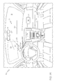
- FIG. 1A is an illustration of a laser-generated windshield display system, including a microprocessor-based controller for controlling the laser and carrying out the method of this invention
- FIG. 1B is a partial cross-sectional view of the illustration of FIG.1A ;
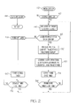
- FIG. 2 is a flow diagram representative of a software routine executed by the microprocessor-based controller of FIG. 1A for carrying out the method of this invention.
- the method of the present invention is illustrated herein in the context of a laser-generated display for the windshield of a motor vehicle, but is more broadly applicable to other displays, automotive or non-automotive, in which a visible or invisible laser beam is directed onto a display surface having a viewable area.
- the display may be used to outline objects in the forward field-of-view as mentioned above, but may alternately or additionally be used to display symbols, messages or selected parameter values to the driver.
- the reference numeral 10 generally designates the forward portion of a motor vehicle passenger compartment, including a windshield 12, a rear-view mirror 14, and the upper surface of an instrument panel 16.
- the reference numeral 18 designates a laser-generated display system according to this invention, including UV laser 20, a microprocessor-based control unit (MCU) 22, a windshield display surface 24, a reflective target 26, and a UV sensor 28.
- the laser 20 generates a collimated UV laser beam that is activated and deflected under the control of MCU 22 via line 30.
- MCU 22 deflects the laser beam onto the display surface 24 as indicated by the reference numeral 32.
- the beam trajectories on the display surface 24 produce corresponding images or display patterns forward of the vehicle driver due light emitted from the display surface 24 when excited by the UV energy of the beam 32.
- the display surface 24 may be a coating of UV-fluorescent material applied to the interior surface of the windshield 12 as depicted in FIG. 1B , or it may be a layer of material sandwiched between two or more layers of windshield glass.
- MCU 22 deflects the laser beam onto the reflective target 26 as indicated by the reference numeral 32'.
- the reflective target 26 is located beyond (below, preferably) the display surface 24, but within the deflection range of laser 20, and may be a small patch of UV-reflective material applied to the interior surface of windshield 12. If the laser 20 is operating correctly, the windshield 12 is intact, and there are no obstructions of the laser beam 32', the reflective target deflects the beam 32' downward as designated by the reference numeral 32" onto the UV sensor 28, which is mounted on or in the upper surface of instrument panel 16.
- the UV sensor 28 provides a feedback signal to MCU 22 via line 34, enabling MCU 22 to confirm proper operation of the system 18 by sampling the sensor output during the test mode. In the event that the expected feedback signal is not received, MCU 22 shuts-down laser 20, and repeats the test procedure following a specified delay interval.
- FIG. 2 depicts a flow diagram representative of a software routine executed by MCU 22 for carrying out the laser control outlined above.
- MCU 22 performs an initialization routine as designated by the block 40, and then executes block 42 to determine if the windshield display function is enabled (by a user-operated switch, for example). If not, the block 44 is executed to power-down laser 20, and the routine is then exited.
- block 46 is executed to deflect the laser beam onto the reflective target 26 at a test-level power level that may be lower than the power level typically used during the normal display mode.
- MCU 22 activates UV sensor 28 and samples its output to determine if the sensor 28 is producing a laser-activated feedback signal. If so, correct operation of the system 18 is confirmed, and the blocks 50-52 are executed to activate the display function of the system.
- MCU 22 processes various inputs and generates the laser trajectories required to generate the desired driver images or display patterns.
- the inputs may include information from vision, radar or other object detection sensors, as well as information about the location of the driver's head.
- block 52 controls the laser deflection, activation and power level to produce the desired images or display patterns.
- the blocks 54-56 establish a suitable update rate (i.e., frame rate) by starting a frame rate timer and comparing the timer value to a specified frame rate time FR_TIME. Once the specified frame rate time is satisfied, blocks 46 and following are re-executed as indicated to repeat the test procedure, and then update the display if the test procedure confirms that the system 18 is operating as expected.
- a suitable update rate i.e., frame rate
- MCU 22 fails to receive a laser-generated feedback signal from the UV sensor 28 at block 48 of the test procedure, blocks 50-56 are bypassed, and the block 58 is executed to immediately turn off laser 20. As indicated above, this may occur due to one of several potential fault conditions, such as misalignment or faulty operation of the laser 20, obstructions of the laser beam path, or loss of the windshield 12. Any of these fault conditions carry the potential for human injury (predominantly eye injury) due to an errant laser beam, and immediately shutting down laser 20 minimizes the risk of any such injury. After turning off laser 20, MCU 22 executes the blocks 60-62 to start a display disable timer and compare the timer value to a specified delay time DL_TIME.
- the delay time DL_TIME will typically be a multiple of the frame rate time FR_TIME, and once the specified delay time is satisfied, blocks 46-48 are re-executed as indicated to repeat the test procedure. If a fault condition is still in effect, blocks 58-62 are re-executed to maintain the laser turn-off condition for at least another delay interval; whereas if the fault condition has been cured, the blocks 50-56 are executed to resume the normal display mode.
- the method of the present invention provides an effective and easily implemented way of minimizing safety risks associated with laser-generated windshield displays.
- the precise cause of the fault condition need not be known, and the normal display mode is automatically resumed if and when the fault condition is cured.
- the system may include more than one reflective target, the reflective target may be a light pipe that collects the laser beam energy and focuses it on the UV sensor 28, and so on.
- the invention equally applies to laser-generated display systems including a laser that emits light in the visible spectrum; thus, the sensor 28 is not necessarily a UV light sensor. Accordingly, it is intended that the invention not be limited to the disclosed embodiment, but that it have the full scope permitted by the language of the following claims.
Abstract
Description
- The present invention relates to laser-generated windshield displays, and more particularly to a method of operation for shutting-down the laser in response to detection of a potentially hazardous fault condition.
- The viability of using an electronically deflected laser beam to create visible patterns on a vehicle windshield has recently been demonstrated. The laser operates in the non-visible ultraviolet (UV) spectrum, and the visible patterns are produced by a windshield coating that emits visible light when excited by the UV laser energy. In a typical implementation, the laser device is mounted forward of the rearview mirror, and directs a laser beam downward onto the interior surface of the windshield forward of the driver. Potential applications include highlighting significant objects or features in the driver field of view such as road edges, signs, pedestrians, and other vehicles to increase the likelihood that they will be comprehended by the driver.
- As with any laser application, care must be taken to detect unusual conditions that present a potential safety hazard to the vehicle occupants or nearby pedestrians, and to shut-down the laser whenever such a condition is detected.
- The present invention is directed to a novel method of operation for a laser-generated windshield display that automatically detects faults that could pose a safety hazard to persons in the vicinity of the display and shuts-down the laser in response to detection of such a fault. During normal operation of the display, the laser beam is deflected onto a display surface that emits light when impinged upon by the laser beam, and the deflection pattern of the laser beam is repeated at a specified frame rate to minimize perceptible flicker of the resulting image. Prior to each frame of the display, the laser beam is deflected in the direction of a reflective target disposed outside the display surface, and a sensor disposed in a reflection path of the reflective target is sampled to detect the presence of a feedback signal that occurs when the laser beam impinges on the sensor. If the feedback signal is detected, the laser beam is deflected onto the display surface to complete the frame; but if the feedback signal is not detected, the laser is automatically turned-off. Once the laser is turned off for lack of a feedback signal, the display process is repeated following a specified delay interval so that the normal display mode will automatically resume when the condition that prevented generation of the feedback signal is cured.
-
FIG. 1A is an illustration of a laser-generated windshield display system, including a microprocessor-based controller for controlling the laser and carrying out the method of this invention; -
FIG. 1B is a partial cross-sectional view of the illustration ofFIG.1A ; and -
FIG. 2 is a flow diagram representative of a software routine executed by the microprocessor-based controller ofFIG. 1A for carrying out the method of this invention. - The method of the present invention is illustrated herein in the context of a laser-generated display for the windshield of a motor vehicle, but is more broadly applicable to other displays, automotive or non-automotive, in which a visible or invisible laser beam is directed onto a display surface having a viewable area. In automotive applications, the display may be used to outline objects in the forward field-of-view as mentioned above, but may alternately or additionally be used to display symbols, messages or selected parameter values to the driver.
- Referring to the drawings, and particularly to
FIGS. 1A-1B , thereference numeral 10 generally designates the forward portion of a motor vehicle passenger compartment, including awindshield 12, a rear-view mirror 14, and the upper surface of aninstrument panel 16. Thereference numeral 18 designates a laser-generated display system according to this invention, includingUV laser 20, a microprocessor-based control unit (MCU) 22, awindshield display surface 24, a reflective target 26, and aUV sensor 28. Thelaser 20 generates a collimated UV laser beam that is activated and deflected under the control ofMCU 22 vialine 30. - When the
system 18 is operating in a normal display mode,MCU 22 deflects the laser beam onto thedisplay surface 24 as indicated by thereference numeral 32. In this mode, the beam trajectories on thedisplay surface 24 produce corresponding images or display patterns forward of the vehicle driver due light emitted from thedisplay surface 24 when excited by the UV energy of thebeam 32. Thedisplay surface 24 may be a coating of UV-fluorescent material applied to the interior surface of thewindshield 12 as depicted inFIG. 1B , or it may be a layer of material sandwiched between two or more layers of windshield glass. - However, when the
system 18 is operating in a test mode,MCU 22 deflects the laser beam onto the reflective target 26 as indicated by the reference numeral 32'. The reflective target 26 is located beyond (below, preferably) thedisplay surface 24, but within the deflection range oflaser 20, and may be a small patch of UV-reflective material applied to the interior surface ofwindshield 12. If thelaser 20 is operating correctly, thewindshield 12 is intact, and there are no obstructions of the laser beam 32', the reflective target deflects the beam 32' downward as designated by thereference numeral 32" onto theUV sensor 28, which is mounted on or in the upper surface ofinstrument panel 16. TheUV sensor 28 provides a feedback signal to MCU 22 vialine 34, enablingMCU 22 to confirm proper operation of thesystem 18 by sampling the sensor output during the test mode. In the event that the expected feedback signal is not received,MCU 22 shuts-downlaser 20, and repeats the test procedure following a specified delay interval. -
FIG. 2 depicts a flow diagram representative of a software routine executed by MCU 22 for carrying out the laser control outlined above. At power-on (for example, at each ignition cycle), MCU 22 performs an initialization routine as designated by theblock 40, and then executesblock 42 to determine if the windshield display function is enabled (by a user-operated switch, for example). If not, theblock 44 is executed to power-downlaser 20, and the routine is then exited. - If the windshield display function is enabled,
block 46 is executed to deflect the laser beam onto the reflective target 26 at a test-level power level that may be lower than the power level typically used during the normal display mode. Atblock 48, MCU 22 activatesUV sensor 28 and samples its output to determine if thesensor 28 is producing a laser-activated feedback signal. If so, correct operation of thesystem 18 is confirmed, and the blocks 50-52 are executed to activate the display function of the system. Atblock 50, MCU 22 processes various inputs and generates the laser trajectories required to generate the desired driver images or display patterns. For example, the inputs may include information from vision, radar or other object detection sensors, as well as information about the location of the driver's head. And after the laser trajectories are generated,block 52 controls the laser deflection, activation and power level to produce the desired images or display patterns. The blocks 54-56 establish a suitable update rate (i.e., frame rate) by starting a frame rate timer and comparing the timer value to a specified frame rate time FR_TIME. Once the specified frame rate time is satisfied,blocks 46 and following are re-executed as indicated to repeat the test procedure, and then update the display if the test procedure confirms that thesystem 18 is operating as expected. - If for any reason, MCU 22 fails to receive a laser-generated feedback signal from the
UV sensor 28 atblock 48 of the test procedure, blocks 50-56 are bypassed, and theblock 58 is executed to immediately turn offlaser 20. As indicated above, this may occur due to one of several potential fault conditions, such as misalignment or faulty operation of thelaser 20, obstructions of the laser beam path, or loss of thewindshield 12. Any of these fault conditions carry the potential for human injury (predominantly eye injury) due to an errant laser beam, and immediately shutting downlaser 20 minimizes the risk of any such injury. After turning offlaser 20, MCU 22 executes the blocks 60-62 to start a display disable timer and compare the timer value to a specified delay time DL_TIME. The delay time DL_TIME will typically be a multiple of the frame rate time FR_TIME, and once the specified delay time is satisfied, blocks 46-48 are re-executed as indicated to repeat the test procedure. If a fault condition is still in effect, blocks 58-62 are re-executed to maintain the laser turn-off condition for at least another delay interval; whereas if the fault condition has been cured, the blocks 50-56 are executed to resume the normal display mode. - In summary, the method of the present invention provides an effective and easily implemented way of minimizing safety risks associated with laser-generated windshield displays. The precise cause of the fault condition need not be known, and the normal display mode is automatically resumed if and when the fault condition is cured.
- While the method has been described with respect to the illustrated system, it is recognized that numerous modifications and variations in addition to those mentioned herein will occur to those skilled in the art. For example, the system may include more than one reflective target, the reflective target may be a light pipe that collects the laser beam energy and focuses it on the
UV sensor 28, and so on. Also, the invention equally applies to laser-generated display systems including a laser that emits light in the visible spectrum; thus, thesensor 28 is not necessarily a UV light sensor. Accordingly, it is intended that the invention not be limited to the disclosed embodiment, but that it have the full scope permitted by the language of the following claims.
Claims (5)
- A method of operation for a laser-generated display (10) where a laser (20) directs a collimated energy beam onto a display region (24), the method of operation comprising the steps of:(a) providing a reflective target (26) that is outside said display region (24) but within a deflection range of said energy beam and a sensor (28) positioned in a beam path (32") that is active when said energy beam impinges on said reflective target (26) and is not otherwise obstructed;(b) controlling (22, 46) said laser (20) to deflect said energy beam in a direction to impinge on said reflective target (26) and sampling (22, 48) an output of said sensor (28) to detect the presence of a feedback signal that occurs when said energy beam is reflected onto said sensor (28) by said reflective target (26); and(c) controlling (22, 50, 52, 58) said laser (20) to deflect said energy beam onto said display region (24) to produce a laser-generated image if the presence of said feedback signal is detected, but otherwise turning-off said laser (20).
- The method of claim 1, including the step of:periodically repeating steps (b) and (c) at a specified repetition rate (22, 54, 56).
- The method of claim 2, including the step of:preventing the periodic repetition of steps (b) and (c) for a specified interval after said laser (20) is turned off due to a failure to detect said feedback signal (22, 60, 62).
- The method of claim 1, where:said display region (24) occupies a portion of a vehicle windshield (12); andsaid sensor (28) is provided on a vehicle instrument panel (16) disposed below the windshield (12).
- The method of claim 1, where:said energy beam comprises light in a non-visible spectrum and said display region (24) emits light when impinged upon by said energy beam.
Applications Claiming Priority (1)
| Application Number | Priority Date | Filing Date | Title |
|---|---|---|---|
| US12/412,470 US8022346B2 (en) | 2009-03-27 | 2009-03-27 | Automatic fault detection and laser shut-down method for a laser-generated windshield display |
Publications (3)
| Publication Number | Publication Date |
|---|---|
| EP2233962A2 true EP2233962A2 (en) | 2010-09-29 |
| EP2233962A3 EP2233962A3 (en) | 2011-07-20 |
| EP2233962B1 EP2233962B1 (en) | 2016-01-06 |
Family
ID=42399628
Family Applications (1)
| Application Number | Title | Priority Date | Filing Date |
|---|---|---|---|
| EP10156104.1A Active EP2233962B1 (en) | 2009-03-27 | 2010-03-10 | Automatic fault detection and laser shut-down method for a laser-generated windshield display |
Country Status (2)
| Country | Link |
|---|---|
| US (1) | US8022346B2 (en) |
| EP (1) | EP2233962B1 (en) |
Cited By (6)
| Publication number | Priority date | Publication date | Assignee | Title |
|---|---|---|---|---|
| WO2013029888A1 (en) | 2011-08-29 | 2013-03-07 | Saint-Gobain Glass France | A device for generating a display image on a composite glass pane |
| EP2693256A1 (en) * | 2012-08-01 | 2014-02-05 | Delphi Technologies, Inc. | Windshield display with obstruction detection |
| EP2693253A1 (en) * | 2012-07-31 | 2014-02-05 | Delphi Technologies, Inc. | Windshield display system |
| US9816027B2 (en) | 2011-04-15 | 2017-11-14 | Sekisui Chemical Co., Ltd. | Method for producing a film having luminescent particles |
| US9855727B2 (en) | 2010-09-21 | 2018-01-02 | Sekisui Chemical Co., Ltd. | Glass pane as head-up display |
| WO2022238050A1 (en) * | 2021-05-10 | 2022-11-17 | Bayerische Motoren Werke Aktiengesellschaft | Method and device for operating a windshield display system with a covered display detection, and windshield display system |
Families Citing this family (6)
| Publication number | Priority date | Publication date | Assignee | Title |
|---|---|---|---|---|
| US8317329B2 (en) * | 2009-04-02 | 2012-11-27 | GM Global Technology Operations LLC | Infotainment display on full-windshield head-up display |
| DE102012206795A1 (en) * | 2012-04-25 | 2013-10-31 | Robert Bosch Gmbh | Method for reducing a light intensity of a projection device |
| FR3013462B1 (en) * | 2013-11-18 | 2017-06-09 | Commissariat Energie Atomique | SYSTEM FOR DISPLAYING AN IMAGE ON A WINDSHIELD |
| US9452709B2 (en) * | 2014-06-18 | 2016-09-27 | Continental Automotive Systems, Inc. | Illuminated instrument cluster |
| EP3687849B1 (en) | 2017-09-28 | 2023-12-20 | Wi-Charge Ltd. | Fail-safe optical wireless power supply |
| US10713919B2 (en) | 2018-11-15 | 2020-07-14 | Raytheon Company | Laser damage detection mechanisms for safety interlock and fault detection |
Citations (4)
| Publication number | Priority date | Publication date | Assignee | Title |
|---|---|---|---|---|
| US20010005262A1 (en) | 1999-12-28 | 2001-06-28 | Sony Corporation | Image projection method and image projector |
| WO2002058402A2 (en) | 2001-01-16 | 2002-07-25 | Ppg Industries Ohio, Inc. | Head-up display system utilizing fluorescent material |
| JP2007094130A (en) | 2005-09-29 | 2007-04-12 | Denso Corp | Optical sensor unit and head-up display device for vehicle provided with the same |
| US20080198335A1 (en) | 2007-02-19 | 2008-08-21 | Denso Corporation | Visible laser beam projector |
Family Cites Families (4)
| Publication number | Priority date | Publication date | Assignee | Title |
|---|---|---|---|---|
| US5428471A (en) | 1992-07-30 | 1995-06-27 | Alcatel Network Systems, Inc. | Fail-safe automatic shut-down apparatus and method for high output power optical communications system |
| US5771114A (en) | 1995-09-29 | 1998-06-23 | Rosemount Inc. | Optical interface with safety shutdown |
| KR100259043B1 (en) | 1998-01-16 | 2000-06-15 | 윤종용 | Method for automatic laser shutdown in optical transmission system |
| US8072686B2 (en) * | 2009-04-02 | 2011-12-06 | GM Global Technology Operations LLC | UV laser beamlett on full-windshield head-up display |
-
2009
- 2009-03-27 US US12/412,470 patent/US8022346B2/en active Active
-
2010
- 2010-03-10 EP EP10156104.1A patent/EP2233962B1/en active Active
Patent Citations (4)
| Publication number | Priority date | Publication date | Assignee | Title |
|---|---|---|---|---|
| US20010005262A1 (en) | 1999-12-28 | 2001-06-28 | Sony Corporation | Image projection method and image projector |
| WO2002058402A2 (en) | 2001-01-16 | 2002-07-25 | Ppg Industries Ohio, Inc. | Head-up display system utilizing fluorescent material |
| JP2007094130A (en) | 2005-09-29 | 2007-04-12 | Denso Corp | Optical sensor unit and head-up display device for vehicle provided with the same |
| US20080198335A1 (en) | 2007-02-19 | 2008-08-21 | Denso Corporation | Visible laser beam projector |
Cited By (13)
| Publication number | Priority date | Publication date | Assignee | Title |
|---|---|---|---|---|
| US10562275B2 (en) | 2010-09-21 | 2020-02-18 | Sekisui Chemical Co., Ltd. | Glass pane as head-up display |
| US9855727B2 (en) | 2010-09-21 | 2018-01-02 | Sekisui Chemical Co., Ltd. | Glass pane as head-up display |
| US9816027B2 (en) | 2011-04-15 | 2017-11-14 | Sekisui Chemical Co., Ltd. | Method for producing a film having luminescent particles |
| CN103748513A (en) * | 2011-08-29 | 2014-04-23 | 法国圣戈班玻璃厂 | A device for generating a display image on a composite glass pane |
| KR20140085418A (en) * | 2011-08-29 | 2014-07-07 | 쌩-고벵 글래스 프랑스 | A device for generating a display image on a composite glass pane |
| JP2014531610A (en) * | 2011-08-29 | 2014-11-27 | サン−ゴバン グラス フランスSaint−Gobain Glass France | Apparatus for generating a display image on a laminated glass plate |
| JP2016130861A (en) * | 2011-08-29 | 2016-07-21 | サン−ゴバン グラス フランスSaint−Gobain Glass France | Method and device for generating display image on laminated glass pane, and building, vehicle, airplane, helicopter or ship having the same |
| CN103748513B (en) * | 2011-08-29 | 2016-08-17 | 法国圣戈班玻璃厂 | Composite glass generates the device of display image |
| WO2013029888A1 (en) | 2011-08-29 | 2013-03-07 | Saint-Gobain Glass France | A device for generating a display image on a composite glass pane |
| US9922621B2 (en) | 2011-08-29 | 2018-03-20 | Sekisui Chemical Co., Ltd. | Device for generating a display image on a composite glass pane |
| EP2693253A1 (en) * | 2012-07-31 | 2014-02-05 | Delphi Technologies, Inc. | Windshield display system |
| EP2693256A1 (en) * | 2012-08-01 | 2014-02-05 | Delphi Technologies, Inc. | Windshield display with obstruction detection |
| WO2022238050A1 (en) * | 2021-05-10 | 2022-11-17 | Bayerische Motoren Werke Aktiengesellschaft | Method and device for operating a windshield display system with a covered display detection, and windshield display system |
Also Published As
| Publication number | Publication date |
|---|---|
| EP2233962A3 (en) | 2011-07-20 |
| EP2233962B1 (en) | 2016-01-06 |
| US20100243858A1 (en) | 2010-09-30 |
| US8022346B2 (en) | 2011-09-20 |
Similar Documents
| Publication | Publication Date | Title |
|---|---|---|
| EP2233962B1 (en) | Automatic fault detection and laser shut-down method for a laser-generated windshield display | |
| JP4354085B2 (en) | Head-up display device for vehicle | |
| US10569649B2 (en) | In-vehicle control apparatus | |
| US8506137B2 (en) | Adaptive front lighting system and control method of the same | |
| US20160257241A1 (en) | Method for calibrating a lighting apparatus | |
| US11039112B2 (en) | Head up display apparatus | |
| US20090140845A1 (en) | Head-up display device for vehicle | |
| US11281000B2 (en) | Head-up display | |
| US10471891B2 (en) | Interior lighting system for an autonomous motor vehicle | |
| US20050140541A1 (en) | Radar scanning method | |
| CN105667400B (en) | A kind of right front blind-area visual monitoring alarm system of vehicle | |
| US20180017794A1 (en) | Detection device, hud and method for operating a hud | |
| JP6970386B2 (en) | Driving support device | |
| CN105620353A (en) | Parking assistant device used for a motor vehicle | |
| US20080198335A1 (en) | Visible laser beam projector | |
| JP2010143463A (en) | Light control glass device | |
| US20050029783A1 (en) | Method for controlling gas pressure of a passenger-side airbag | |
| CN110293928A (en) | A kind of automobile intelligent blind zone detection method and system | |
| US20190106049A1 (en) | Method for controlling the light distribution of a headlamp assembly, and headlamp assembly | |
| JP6658483B2 (en) | Display control device for vehicle and display system for vehicle | |
| JP2010264916A (en) | Wiper | |
| KR102621552B1 (en) | Operation Apparatus for Active Hood linked with ADAS and the Method thereof | |
| JP2019164247A (en) | Optical scan device, image display device, and moving body | |
| EP4183629A1 (en) | System and method for adjusting the emission direction of a motor-vehicle headlight unit | |
| US20230398935A1 (en) | Electronic inner mirror device, notification control method therefor, and notification control program therefor |
Legal Events
| Date | Code | Title | Description |
|---|---|---|---|
| PUAI | Public reference made under article 153(3) epc to a published international application that has entered the european phase |
Free format text: ORIGINAL CODE: 0009012 |
|
| AK | Designated contracting states |
Kind code of ref document: A2 Designated state(s): AT BE BG CH CY CZ DE DK EE ES FI FR GB GR HR HU IE IS IT LI LT LU LV MC MK MT NL NO PL PT RO SE SI SK SM TR |
|
| AX | Request for extension of the european patent |
Extension state: AL BA ME RS |
|
| PUAL | Search report despatched |
Free format text: ORIGINAL CODE: 0009013 |
|
| AK | Designated contracting states |
Kind code of ref document: A3 Designated state(s): AT BE BG CH CY CZ DE DK EE ES FI FR GB GR HR HU IE IS IT LI LT LU LV MC MK MT NL NO PL PT RO SE SI SK SM TR |
|
| AX | Request for extension of the european patent |
Extension state: AL BA ME RS |
|
| 17P | Request for examination filed |
Effective date: 20120120 |
|
| 17Q | First examination report despatched |
Effective date: 20120911 |
|
| GRAP | Despatch of communication of intention to grant a patent |
Free format text: ORIGINAL CODE: EPIDOSNIGR1 |
|
| INTG | Intention to grant announced |
Effective date: 20150720 |
|
| GRAS | Grant fee paid |
Free format text: ORIGINAL CODE: EPIDOSNIGR3 |
|
| GRAA | (expected) grant |
Free format text: ORIGINAL CODE: 0009210 |
|
| AK | Designated contracting states |
Kind code of ref document: B1 Designated state(s): AT BE BG CH CY CZ DE DK EE ES FI FR GB GR HR HU IE IS IT LI LT LU LV MC MK MT NL NO PL PT RO SE SI SK SM TR |
|
| REG | Reference to a national code |
Ref country code: GB Ref legal event code: FG4D |
|
| REG | Reference to a national code |
Ref country code: CH Ref legal event code: EP |
|
| REG | Reference to a national code |
Ref country code: IE Ref legal event code: FG4D |
|
| REG | Reference to a national code |
Ref country code: AT Ref legal event code: REF Ref document number: 769333 Country of ref document: AT Kind code of ref document: T Effective date: 20160215 |
|
| REG | Reference to a national code |
Ref country code: DE Ref legal event code: R096 Ref document number: 602010029826 Country of ref document: DE |
|
| REG | Reference to a national code |
Ref country code: FR Ref legal event code: PLFP Year of fee payment: 7 |
|
| REG | Reference to a national code |
Ref country code: LT Ref legal event code: MG4D |
|
| REG | Reference to a national code |
Ref country code: NL Ref legal event code: MP Effective date: 20160106 |
|
| REG | Reference to a national code |
Ref country code: AT Ref legal event code: MK05 Ref document number: 769333 Country of ref document: AT Kind code of ref document: T Effective date: 20160106 |
|
| PG25 | Lapsed in a contracting state [announced via postgrant information from national office to epo] |
Ref country code: NL Free format text: LAPSE BECAUSE OF FAILURE TO SUBMIT A TRANSLATION OF THE DESCRIPTION OR TO PAY THE FEE WITHIN THE PRESCRIBED TIME-LIMIT Effective date: 20160106 |
|
| PG25 | Lapsed in a contracting state [announced via postgrant information from national office to epo] |
Ref country code: NO Free format text: LAPSE BECAUSE OF FAILURE TO SUBMIT A TRANSLATION OF THE DESCRIPTION OR TO PAY THE FEE WITHIN THE PRESCRIBED TIME-LIMIT Effective date: 20160406 Ref country code: GR Free format text: LAPSE BECAUSE OF FAILURE TO SUBMIT A TRANSLATION OF THE DESCRIPTION OR TO PAY THE FEE WITHIN THE PRESCRIBED TIME-LIMIT Effective date: 20160407 Ref country code: IT Free format text: LAPSE BECAUSE OF FAILURE TO SUBMIT A TRANSLATION OF THE DESCRIPTION OR TO PAY THE FEE WITHIN THE PRESCRIBED TIME-LIMIT Effective date: 20160106 Ref country code: HR Free format text: LAPSE BECAUSE OF FAILURE TO SUBMIT A TRANSLATION OF THE DESCRIPTION OR TO PAY THE FEE WITHIN THE PRESCRIBED TIME-LIMIT Effective date: 20160106 Ref country code: ES Free format text: LAPSE BECAUSE OF FAILURE TO SUBMIT A TRANSLATION OF THE DESCRIPTION OR TO PAY THE FEE WITHIN THE PRESCRIBED TIME-LIMIT Effective date: 20160106 Ref country code: FI Free format text: LAPSE BECAUSE OF FAILURE TO SUBMIT A TRANSLATION OF THE DESCRIPTION OR TO PAY THE FEE WITHIN THE PRESCRIBED TIME-LIMIT Effective date: 20160106 |
|
| PG25 | Lapsed in a contracting state [announced via postgrant information from national office to epo] |
Ref country code: AT Free format text: LAPSE BECAUSE OF FAILURE TO SUBMIT A TRANSLATION OF THE DESCRIPTION OR TO PAY THE FEE WITHIN THE PRESCRIBED TIME-LIMIT Effective date: 20160106 Ref country code: LV Free format text: LAPSE BECAUSE OF FAILURE TO SUBMIT A TRANSLATION OF THE DESCRIPTION OR TO PAY THE FEE WITHIN THE PRESCRIBED TIME-LIMIT Effective date: 20160106 Ref country code: PL Free format text: LAPSE BECAUSE OF FAILURE TO SUBMIT A TRANSLATION OF THE DESCRIPTION OR TO PAY THE FEE WITHIN THE PRESCRIBED TIME-LIMIT Effective date: 20160106 Ref country code: PT Free format text: LAPSE BECAUSE OF FAILURE TO SUBMIT A TRANSLATION OF THE DESCRIPTION OR TO PAY THE FEE WITHIN THE PRESCRIBED TIME-LIMIT Effective date: 20160506 Ref country code: SE Free format text: LAPSE BECAUSE OF FAILURE TO SUBMIT A TRANSLATION OF THE DESCRIPTION OR TO PAY THE FEE WITHIN THE PRESCRIBED TIME-LIMIT Effective date: 20160106 Ref country code: LT Free format text: LAPSE BECAUSE OF FAILURE TO SUBMIT A TRANSLATION OF THE DESCRIPTION OR TO PAY THE FEE WITHIN THE PRESCRIBED TIME-LIMIT Effective date: 20160106 Ref country code: IS Free format text: LAPSE BECAUSE OF FAILURE TO SUBMIT A TRANSLATION OF THE DESCRIPTION OR TO PAY THE FEE WITHIN THE PRESCRIBED TIME-LIMIT Effective date: 20160506 Ref country code: BE Free format text: LAPSE BECAUSE OF NON-PAYMENT OF DUE FEES Effective date: 20160331 |
|
| REG | Reference to a national code |
Ref country code: DE Ref legal event code: R097 Ref document number: 602010029826 Country of ref document: DE |
|
| PG25 | Lapsed in a contracting state [announced via postgrant information from national office to epo] |
Ref country code: DK Free format text: LAPSE BECAUSE OF FAILURE TO SUBMIT A TRANSLATION OF THE DESCRIPTION OR TO PAY THE FEE WITHIN THE PRESCRIBED TIME-LIMIT Effective date: 20160106 Ref country code: EE Free format text: LAPSE BECAUSE OF FAILURE TO SUBMIT A TRANSLATION OF THE DESCRIPTION OR TO PAY THE FEE WITHIN THE PRESCRIBED TIME-LIMIT Effective date: 20160106 Ref country code: MC Free format text: LAPSE BECAUSE OF FAILURE TO SUBMIT A TRANSLATION OF THE DESCRIPTION OR TO PAY THE FEE WITHIN THE PRESCRIBED TIME-LIMIT Effective date: 20160106 Ref country code: LU Free format text: LAPSE BECAUSE OF FAILURE TO SUBMIT A TRANSLATION OF THE DESCRIPTION OR TO PAY THE FEE WITHIN THE PRESCRIBED TIME-LIMIT Effective date: 20160310 |
|
| REG | Reference to a national code |
Ref country code: CH Ref legal event code: PL |
|
| PLBE | No opposition filed within time limit |
Free format text: ORIGINAL CODE: 0009261 |
|
| STAA | Information on the status of an ep patent application or granted ep patent |
Free format text: STATUS: NO OPPOSITION FILED WITHIN TIME LIMIT |
|
| PG25 | Lapsed in a contracting state [announced via postgrant information from national office to epo] |
Ref country code: CZ Free format text: LAPSE BECAUSE OF FAILURE TO SUBMIT A TRANSLATION OF THE DESCRIPTION OR TO PAY THE FEE WITHIN THE PRESCRIBED TIME-LIMIT Effective date: 20160106 Ref country code: SM Free format text: LAPSE BECAUSE OF FAILURE TO SUBMIT A TRANSLATION OF THE DESCRIPTION OR TO PAY THE FEE WITHIN THE PRESCRIBED TIME-LIMIT Effective date: 20160106 Ref country code: SK Free format text: LAPSE BECAUSE OF FAILURE TO SUBMIT A TRANSLATION OF THE DESCRIPTION OR TO PAY THE FEE WITHIN THE PRESCRIBED TIME-LIMIT Effective date: 20160106 Ref country code: RO Free format text: LAPSE BECAUSE OF FAILURE TO SUBMIT A TRANSLATION OF THE DESCRIPTION OR TO PAY THE FEE WITHIN THE PRESCRIBED TIME-LIMIT Effective date: 20160106 |
|
| 26N | No opposition filed |
Effective date: 20161007 |
|
| REG | Reference to a national code |
Ref country code: IE Ref legal event code: MM4A |
|
| PG25 | Lapsed in a contracting state [announced via postgrant information from national office to epo] |
Ref country code: BE Free format text: LAPSE BECAUSE OF FAILURE TO SUBMIT A TRANSLATION OF THE DESCRIPTION OR TO PAY THE FEE WITHIN THE PRESCRIBED TIME-LIMIT Effective date: 20160106 |
|
| PG25 | Lapsed in a contracting state [announced via postgrant information from national office to epo] |
Ref country code: CH Free format text: LAPSE BECAUSE OF NON-PAYMENT OF DUE FEES Effective date: 20160331 Ref country code: LI Free format text: LAPSE BECAUSE OF NON-PAYMENT OF DUE FEES Effective date: 20160331 Ref country code: IE Free format text: LAPSE BECAUSE OF NON-PAYMENT OF DUE FEES Effective date: 20160310 |
|
| PG25 | Lapsed in a contracting state [announced via postgrant information from national office to epo] |
Ref country code: BG Free format text: LAPSE BECAUSE OF FAILURE TO SUBMIT A TRANSLATION OF THE DESCRIPTION OR TO PAY THE FEE WITHIN THE PRESCRIBED TIME-LIMIT Effective date: 20160406 Ref country code: SI Free format text: LAPSE BECAUSE OF FAILURE TO SUBMIT A TRANSLATION OF THE DESCRIPTION OR TO PAY THE FEE WITHIN THE PRESCRIBED TIME-LIMIT Effective date: 20160106 |
|
| REG | Reference to a national code |
Ref country code: FR Ref legal event code: PLFP Year of fee payment: 8 |
|
| PG25 | Lapsed in a contracting state [announced via postgrant information from national office to epo] |
Ref country code: MT Free format text: LAPSE BECAUSE OF FAILURE TO SUBMIT A TRANSLATION OF THE DESCRIPTION OR TO PAY THE FEE WITHIN THE PRESCRIBED TIME-LIMIT Effective date: 20160106 |
|
| REG | Reference to a national code |
Ref country code: FR Ref legal event code: PLFP Year of fee payment: 9 |
|
| PG25 | Lapsed in a contracting state [announced via postgrant information from national office to epo] |
Ref country code: CY Free format text: LAPSE BECAUSE OF FAILURE TO SUBMIT A TRANSLATION OF THE DESCRIPTION OR TO PAY THE FEE WITHIN THE PRESCRIBED TIME-LIMIT Effective date: 20160106 Ref country code: HU Free format text: LAPSE BECAUSE OF FAILURE TO SUBMIT A TRANSLATION OF THE DESCRIPTION OR TO PAY THE FEE WITHIN THE PRESCRIBED TIME-LIMIT; INVALID AB INITIO Effective date: 20100310 |
|
| PG25 | Lapsed in a contracting state [announced via postgrant information from national office to epo] |
Ref country code: MK Free format text: LAPSE BECAUSE OF FAILURE TO SUBMIT A TRANSLATION OF THE DESCRIPTION OR TO PAY THE FEE WITHIN THE PRESCRIBED TIME-LIMIT Effective date: 20160106 Ref country code: MT Free format text: LAPSE BECAUSE OF FAILURE TO SUBMIT A TRANSLATION OF THE DESCRIPTION OR TO PAY THE FEE WITHIN THE PRESCRIBED TIME-LIMIT Effective date: 20160331 Ref country code: TR Free format text: LAPSE BECAUSE OF FAILURE TO SUBMIT A TRANSLATION OF THE DESCRIPTION OR TO PAY THE FEE WITHIN THE PRESCRIBED TIME-LIMIT Effective date: 20160106 |
|
| REG | Reference to a national code |
Ref country code: DE Ref legal event code: R081 Ref document number: 602010029826 Country of ref document: DE Owner name: APTIV TECHNOLOGIES LIMITED, BB Free format text: FORMER OWNER: DELPHI TECHNOLOGIES, INC., TROY, MICH., US |
|
| REG | Reference to a national code |
Ref country code: GB Ref legal event code: 732E Free format text: REGISTERED BETWEEN 20190117 AND 20190123 |
|
| REG | Reference to a national code |
Ref country code: GB Ref legal event code: 732E Free format text: REGISTERED BETWEEN 20190124 AND 20190130 |
|
| PGFP | Annual fee paid to national office [announced via postgrant information from national office to epo] |
Ref country code: FR Payment date: 20230325 Year of fee payment: 14 |
|
| PGFP | Annual fee paid to national office [announced via postgrant information from national office to epo] |
Ref country code: GB Payment date: 20230317 Year of fee payment: 14 Ref country code: DE Payment date: 20230314 Year of fee payment: 14 |
|
| P01 | Opt-out of the competence of the unified patent court (upc) registered |
Effective date: 20230425 |