EP2228086A1 - Atomiser - Google Patents
Atomiser Download PDFInfo
- Publication number
- EP2228086A1 EP2228086A1 EP10003922A EP10003922A EP2228086A1 EP 2228086 A1 EP2228086 A1 EP 2228086A1 EP 10003922 A EP10003922 A EP 10003922A EP 10003922 A EP10003922 A EP 10003922A EP 2228086 A1 EP2228086 A1 EP 2228086A1
- Authority
- EP
- European Patent Office
- Prior art keywords
- atomiser
- cover
- reservoir
- amino
- formulation
- Prior art date
- Legal status (The legal status is an assumption and is not a legal conclusion. Google has not performed a legal analysis and makes no representation as to the accuracy of the status listed.)
- Granted
Links
Images


Classifications
-
- A—HUMAN NECESSITIES
- A61—MEDICAL OR VETERINARY SCIENCE; HYGIENE
- A61M—DEVICES FOR INTRODUCING MEDIA INTO, OR ONTO, THE BODY; DEVICES FOR TRANSDUCING BODY MEDIA OR FOR TAKING MEDIA FROM THE BODY; DEVICES FOR PRODUCING OR ENDING SLEEP OR STUPOR
- A61M15/00—Inhalators
- A61M15/009—Inhalators using medicine packages with incorporated spraying means, e.g. aerosol cans
-
- A—HUMAN NECESSITIES
- A61—MEDICAL OR VETERINARY SCIENCE; HYGIENE
- A61M—DEVICES FOR INTRODUCING MEDIA INTO, OR ONTO, THE BODY; DEVICES FOR TRANSDUCING BODY MEDIA OR FOR TAKING MEDIA FROM THE BODY; DEVICES FOR PRODUCING OR ENDING SLEEP OR STUPOR
- A61M11/00—Sprayers or atomisers specially adapted for therapeutic purposes
- A61M11/006—Sprayers or atomisers specially adapted for therapeutic purposes operated by applying mechanical pressure to the liquid to be sprayed or atomised
-
- A—HUMAN NECESSITIES
- A61—MEDICAL OR VETERINARY SCIENCE; HYGIENE
- A61M—DEVICES FOR INTRODUCING MEDIA INTO, OR ONTO, THE BODY; DEVICES FOR TRANSDUCING BODY MEDIA OR FOR TAKING MEDIA FROM THE BODY; DEVICES FOR PRODUCING OR ENDING SLEEP OR STUPOR
- A61M11/00—Sprayers or atomisers specially adapted for therapeutic purposes
- A61M11/02—Sprayers or atomisers specially adapted for therapeutic purposes operated by air or other gas pressure applied to the liquid or other product to be sprayed or atomised
-
- A—HUMAN NECESSITIES
- A61—MEDICAL OR VETERINARY SCIENCE; HYGIENE
- A61M—DEVICES FOR INTRODUCING MEDIA INTO, OR ONTO, THE BODY; DEVICES FOR TRANSDUCING BODY MEDIA OR FOR TAKING MEDIA FROM THE BODY; DEVICES FOR PRODUCING OR ENDING SLEEP OR STUPOR
- A61M15/00—Inhalators
-
- A—HUMAN NECESSITIES
- A61—MEDICAL OR VETERINARY SCIENCE; HYGIENE
- A61M—DEVICES FOR INTRODUCING MEDIA INTO, OR ONTO, THE BODY; DEVICES FOR TRANSDUCING BODY MEDIA OR FOR TAKING MEDIA FROM THE BODY; DEVICES FOR PRODUCING OR ENDING SLEEP OR STUPOR
- A61M15/00—Inhalators
- A61M15/0001—Details of inhalators; Constructional features thereof
- A61M15/0021—Mouthpieces therefor
- A61M15/0025—Mouthpieces therefor with caps
- A61M15/0026—Hinged caps
-
- A—HUMAN NECESSITIES
- A61—MEDICAL OR VETERINARY SCIENCE; HYGIENE
- A61M—DEVICES FOR INTRODUCING MEDIA INTO, OR ONTO, THE BODY; DEVICES FOR TRANSDUCING BODY MEDIA OR FOR TAKING MEDIA FROM THE BODY; DEVICES FOR PRODUCING OR ENDING SLEEP OR STUPOR
- A61M15/00—Inhalators
- A61M15/0028—Inhalators using prepacked dosages, one for each application, e.g. capsules to be perforated or broken-up
- A61M15/0045—Inhalators using prepacked dosages, one for each application, e.g. capsules to be perforated or broken-up using multiple prepacked dosages on a same carrier, e.g. blisters
- A61M15/0046—Inhalators using prepacked dosages, one for each application, e.g. capsules to be perforated or broken-up using multiple prepacked dosages on a same carrier, e.g. blisters characterized by the type of carrier
- A61M15/0048—Inhalators using prepacked dosages, one for each application, e.g. capsules to be perforated or broken-up using multiple prepacked dosages on a same carrier, e.g. blisters characterized by the type of carrier the dosages being arranged in a plane, e.g. on diskettes
-
- A—HUMAN NECESSITIES
- A61—MEDICAL OR VETERINARY SCIENCE; HYGIENE
- A61M—DEVICES FOR INTRODUCING MEDIA INTO, OR ONTO, THE BODY; DEVICES FOR TRANSDUCING BODY MEDIA OR FOR TAKING MEDIA FROM THE BODY; DEVICES FOR PRODUCING OR ENDING SLEEP OR STUPOR
- A61M15/00—Inhalators
- A61M15/0028—Inhalators using prepacked dosages, one for each application, e.g. capsules to be perforated or broken-up
- A61M15/0045—Inhalators using prepacked dosages, one for each application, e.g. capsules to be perforated or broken-up using multiple prepacked dosages on a same carrier, e.g. blisters
- A61M15/0046—Inhalators using prepacked dosages, one for each application, e.g. capsules to be perforated or broken-up using multiple prepacked dosages on a same carrier, e.g. blisters characterized by the type of carrier
- A61M15/005—Inhalators using prepacked dosages, one for each application, e.g. capsules to be perforated or broken-up using multiple prepacked dosages on a same carrier, e.g. blisters characterized by the type of carrier the dosages being arranged on a cylindrical surface
-
- A—HUMAN NECESSITIES
- A61—MEDICAL OR VETERINARY SCIENCE; HYGIENE
- A61M—DEVICES FOR INTRODUCING MEDIA INTO, OR ONTO, THE BODY; DEVICES FOR TRANSDUCING BODY MEDIA OR FOR TAKING MEDIA FROM THE BODY; DEVICES FOR PRODUCING OR ENDING SLEEP OR STUPOR
- A61M15/00—Inhalators
- A61M15/0028—Inhalators using prepacked dosages, one for each application, e.g. capsules to be perforated or broken-up
- A61M15/0061—Inhalators using prepacked dosages, one for each application, e.g. capsules to be perforated or broken-up using pre-packed dosages having an insert inside
-
- A—HUMAN NECESSITIES
- A61—MEDICAL OR VETERINARY SCIENCE; HYGIENE
- A61M—DEVICES FOR INTRODUCING MEDIA INTO, OR ONTO, THE BODY; DEVICES FOR TRANSDUCING BODY MEDIA OR FOR TAKING MEDIA FROM THE BODY; DEVICES FOR PRODUCING OR ENDING SLEEP OR STUPOR
- A61M15/00—Inhalators
- A61M15/0065—Inhalators with dosage or measuring devices
- A61M15/0068—Indicating or counting the number of dispensed doses or of remaining doses
- A61M15/007—Mechanical counters
- A61M15/0071—Mechanical counters having a display or indicator
- A61M15/0075—Mechanical counters having a display or indicator on a disc
-
- A—HUMAN NECESSITIES
- A61—MEDICAL OR VETERINARY SCIENCE; HYGIENE
- A61M—DEVICES FOR INTRODUCING MEDIA INTO, OR ONTO, THE BODY; DEVICES FOR TRANSDUCING BODY MEDIA OR FOR TAKING MEDIA FROM THE BODY; DEVICES FOR PRODUCING OR ENDING SLEEP OR STUPOR
- A61M15/00—Inhalators
- A61M15/0065—Inhalators with dosage or measuring devices
- A61M15/0068—Indicating or counting the number of dispensed doses or of remaining doses
- A61M15/0083—Timers
-
- B—PERFORMING OPERATIONS; TRANSPORTING
- B05—SPRAYING OR ATOMISING IN GENERAL; APPLYING FLUENT MATERIALS TO SURFACES, IN GENERAL
- B05B—SPRAYING APPARATUS; ATOMISING APPARATUS; NOZZLES
- B05B11/00—Single-unit hand-held apparatus in which flow of contents is produced by the muscular force of the operator at the moment of use
- B05B11/01—Single-unit hand-held apparatus in which flow of contents is produced by the muscular force of the operator at the moment of use characterised by the means producing the flow
- B05B11/06—Gas or vapour producing the flow, e.g. from a compressible bulb or air pump
-
- A—HUMAN NECESSITIES
- A61—MEDICAL OR VETERINARY SCIENCE; HYGIENE
- A61M—DEVICES FOR INTRODUCING MEDIA INTO, OR ONTO, THE BODY; DEVICES FOR TRANSDUCING BODY MEDIA OR FOR TAKING MEDIA FROM THE BODY; DEVICES FOR PRODUCING OR ENDING SLEEP OR STUPOR
- A61M2202/00—Special media to be introduced, removed or treated
- A61M2202/06—Solids
- A61M2202/064—Powder
Definitions
- the present invention relates to an atomiser according to the preamble of claims 1.
- the present invention relates in particular to the delivery and atomisation of a formulation for inhalation or for other medical or therapeutic purposes.
- the present invention relates to the delivery of medical, pharmaceutical and/or therapeutic formulations which in particular contain or consist of at least one active substance.
- the present invention relates in particular to an inhaler.
- an aerosol or a spray cloud is produced having, particularly for inhalation, very fine, solid and/or liquid particles, preferably in the range from 1 to 10 ⁇ m.
- the formulation is preferably a powder.
- the invention therefore relates to a powder inhaler.
- the term "formulation" according to the present invention preferably also includes liquids, however, while the term “liquid” is to be understood in a broader sense as including inter alia solutions, suspensions, suslutions (mixture of solution and suspension), dispersions, mixtures thereof or the like.
- the present invention relates in particular to an atomiser with a pre-metered formulation.
- the individual doses are contained in separate receptacles such as chambers, blister pouches, inserts, capsules or the like, and can be individually taken out and atomised.
- passive and active atomisers there are passive and active atomisers.
- the passive type the formulation is expelled through the air current produced by the user on inhaling or breathing in.
- the active type the formulation is expelled independently of the breathing in during inhaling, and the delivery can be triggered by the inhalation process - in particular by so-called breath triggering.
- a current of a delivery medium such as air or some other gas is generated by the atomiser or inhaler itself in order to deliver the formulation.
- the atomiser has a delivery device such as an air pump or a pressurised gas container.
- EP 0 950 423 B1 discloses an active dispenser for media, particularly powders, with a compressed air pump, namely a piston pump, integrated in the dispenser.
- the dispenser has a blister disc with blister pouches containing the powder arranged in a circle. To actuate or open the individual blister pouches the housing part is moved axially.
- EP 1 132 104 B1 discloses an active dispenser for delivering a medium containing at least one pharmaceutical active substance from a blister strip.
- the dispenser has a pump for a fluid, particularly air, for expelling the medium, an impact spike for creating a fluid connection between the pump and a blister pouch and a lateral actuating device which when actuated both positions a blister pouch in relation to the impact spike and also brings about the expulsion of the medium.
- the dispenser also has a spring which is under tension during a first actuating step and can be released into a relaxed position during a second actuating step by releasing a latch, the spring successively causing the blister pouch to be positioned in relation to the impact spike, the blister pouch to be opened by the impact spike and air to be supplied to the blister pouch in order to expel the medium.
- WO 91/06333 A1 discloses an active dispenser having a hollow cylindrical reservoir comprising a plurality of axially extending chambers containing powder. By axially pushing the dispenser together air is compressed in a piston pump and is finally conveyed through the respective chamber in order to expel the respective dose of powder.
- US 5,533,502 A discloses a passive powder inhaler having an annular reservoir, particularly a blister, having a plurality of receptacles for powder.
- the reservoir is rotatably held in the inhaler by a carrier.
- the carrier can be rotated by means of an axially protruding knob to select the next receptacle and can be moved axially in order to pierce the receptacle.
- this does not allow easy operation.
- the user has to hold the knob or carrier in the axially displaced state during inhalation. After being released the carrier with the reservoir returns to its axial starting position away from the piercing elements by the effect of spring force.
- WO 2005/037353 A1 discloses a passive inhaler with a strip of blisters which can be punctured by means of a pivotable actuator.
- the actuator comprises a mouthpiece and means for puncturing blisters.
- the blisterstrip can be advanced by pivoting the actuator.
- the actuator is coupled to a cap covering the mouthpiece so that a blister is pierced when the cap is opened and indexed to move the next unused blister into position aperture in the housing when the cap is closed.
- the actuator is lifted when is the cap is closed so that a compact structure can not be achieved. If the actuator is not lifted, the next blister would be punctured due to the advancing of the blister strip when closing the cap.
- Object of the present invention is to provide an atomiser which can be operated very simply, particularly intuitively, while being simple and inexpensive in its construction, and which allows or has a compact structure, particularly a low overall height.
- the atomiser has a gear or transmission for producing, from the opening and/or closing movement of the cover, a preferably axial movement to open the next receptacle, for displacing and/or advancing the store by one receptacle, for tensioning a spring store, for actuating a delivery device, particularly for taking in air, and/or for actuating a counter or other device of the atomiser.
- a gear or transmission for producing, from the opening and/or closing movement of the cover, a preferably axial movement to open the next receptacle, for displacing and/or advancing the store by one receptacle, for tensioning a spring store, for actuating a delivery device, particularly for taking in air, and/or for actuating a counter or other device of the atomiser.
- the covering of the mouthpiece of the atomiser is coupled to a delivery device such as a pump and/or to an energy store such as a spring store such that opening and/or closing the cover actuates the delivery device and/or generates energy and this is stored in the energy store.
- a delivery medium preferably air
- energy produced by opening and/or closing the cover is preferably stored by tensioning the spring store.
- the atomiser has a closable chamber for accommodating medicaments independently of the reservoir. This results in a simple, compact construction with increased medicament capacity.
- Fig. 1 shows in schematic section a proposed atomiser 1 according to a first embodiment in the transportation position.
- it is a preferably portable inhaler, particularly preferably for aerosol therapy.
- the atomiser 1 is designed to deliver and atomise a formulation 2, preferably powder.
- a formulation 2 preferably powder.
- the atomiser 1 can be used for a formulation 2 in the sense explained hereinbefore.
- the formulation 2 is preferably pre-metered into individual doses which can be delivered one after another by the atomiser 1, particularly for inhalation.
- the atomiser 1 has a reservoir 3 or is designed to hold one. If necessary the reservoir 3 can be inserted in the atomiser 1 and optionally replaced for repeated use of the atomiser 1.
- the reservoir 3 has a plurality of receptacles 4, each containing one dose of the formulation 2.
- the receptacles 4 may be e.g. blister pockets, but preferably contain inserts 28 with the respective dose of the formulation 2.
- the reservoir 3 is preferably of rigid and/or annular construction. In particular the reservoir 3 or the receptacles 4 form an annular arrangement, the receptacles 4 preferably being distributed around the circumference of the reservoir 3.
- the atomiser 1 is preferably of the active type.
- the atomiser 1 preferably has a delivery device 5 for a delivery medium, particularly air or some other gas, for delivering the formulation 2.
- the delivery device 5 is constructed in particular as a pump, particularly preferably an air pump, or is designed in some other way to convey the delivery medium.
- the delivery device 5 has a pump chamber 6 which is preferably formed, delimited and/or variable by a bellows 7 and/or some other element of the delivery device 5.
- the delivery device 5 ambient air, in particular, can be taken in as the delivery medium and put under pressure.
- the formulation 2 i.e. a dose of the formulation 2 can be expelled from a receptacle 4 on actuation or use of the atomiser 1, in particularly only after it has been triggered accordingly.
- the delivery device 5 may theoretically also produce, provide and/or pressurise air, other gas or even liquid as the delivery medium in some other way, so as to be able to deliver the formulation 2 particularly as an aerosol or spray mist with preferably fine particles (solid and/or liquid).
- the atomiser 1 preferably has an endpiece or mouthpiece 8 for delivering the formulation 2, in particular to a user or patient (not shown). From now on only the term “mouthpiece” will be used. However, this may also be some other endpiece for administering or delivering the formulation 2, particularly when the atomiser 1 is not used as an inhaler.
- a delivery opening of the mouthpiece 8 is preferably provided with a grid 9 or other protective element, particularly in order to be able to prevent damage to the atomiser 1, e.g. of the reservoir 3 or receptacles 4, caused by external effects or the like, and/or to prevent the expulsion of other parts, larger particles or the like.
- the atomiser 1 preferably has a cover 10 associated with the mouthpiece 8, which is manually movable, in particular, to enable the mouthpiece 8 to be opened and closed.
- Fig. 1 shows the cover 10 in the closed state, i.e. covering the mouthpiece 8.
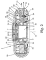
- Fig. 2 shows in a similar sectional view the activated atomiser 1, i.e. the atomiser 1 ready for inhalation, with the cover 10 open, i.e. the mouthpiece 8 freely accessible.
- the cover 10 is movable in particular at right angles to the delivery direction 11 indicated in Fig. 2 , in particular slidable and/or pivotable.
- the cover 10 is optionally pivotable or rotatable about a central axis 12 of the atomiser 1 or the annular arrangement of the reservoir 3 or the receptacles 4 or a rotation axis of the reservoir 3.
- the atomiser 1 or its housing 13 is preferably at least substantially rotationally symmetrical, particularly relative to the axis 12, and/or constructed to be at least substantially flat or disc-shaped, in particular substantially in the form of a circular disc.
- other geometric and constructive solutions and arrangements are also possible.
- the cover 10 is preferably movable at a tangent to the housing 13 of the atomiser 1 or along a periphery of the atomiser 1.
- the cover 10 extends in particular substantially peripherally, in particular along a circumferential section of the atomiser 1.
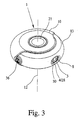
- Fig. 3 shows a preferred construction, particularly a flat, disc-shaped and/or round embodiment of the atomiser 1. It is also apparent that the cover 10 covers or overlaps a circumferential portion of the atomiser 1 of preferably at least 90°, in particular substantially about 150° to 170°, particularly both in the peripheral direction and also from one flat side through the circumferential portion to the other.
- cover 10 covers or overlaps a circumferential portion of the atomiser 1 of preferably at least 90°, in particular substantially about 150° to 170°, particularly both in the peripheral direction and also from one flat side through the circumferential portion to the other.
- cover 10 covers or overlaps a circumferential portion of the atomiser 1 of preferably at least 90°, in particular substantially about 150° to 170°, particularly both in the peripheral direction and also from one flat side through the circumferential portion to the other.
- other constructive solutions and configurations are also possible.
- the cover 10 is preferably rotated or pivoted through about 150° to 180° relative to the closed transportation position shown in Fig. 1 .
- other pivot angles are also possible.
- the cover 10 may be formed for example in the manner of a slide and/or shutter and may be guided, mounted or held for example by the housing 13 or mouthpiece 8.
- the cover 10 is preferably coupled to the delivery device 5 such that by opening and/or closing, and in particular simply by opening, the cover 10 the delivery device 5 is operated or actuated and in particular the delivery medium (particularly ambient air) is taken in by the delivery device 5.
- the delivery medium can be put under pressure by the opening and/or closing movement of the cover 10. In this case operation is very simple and intuitive, as the actuation of the delivery device 5 is intuitively effected by opening and/or closing the cover 10 and in particular there is no need for any additional actuation of any other actuating element.
- the atomiser 1 or delivery device 5 preferably has an energy store, particularly a spring store, in the form of a spring 14 in the embodiment shown.
- the cover 10 is preferably coupled to the energy store such that energy is produced by opening and/or closing the cover 10 and stored in the energy store. In particular opening and/or closing - particularly preferably just closing - the cover 10 causes energy to be stored by tensioning the spring store or the spring 14.
- the energy store or spring store may drive various devices and/or serve different purposes and serves in particular to drive the delivery device 5 or to put the delivery medium under pressure or displace it from the pump chamber 6, in order to convey the delivery medium through a receptacle and expel the corresponding dose of the formulation 2 in the desired manner and then atomise it.
- the delivery medium is preferably only put under pressure during or for the purpose of delivering the formulation 2. However, in theory this may also take place beforehand, in which case a valve device or the like (not shown) is provided in particular to prevent premature delivery of the delivery medium and the formulation 2 before the actual desired delivery and atomisation.
- the energy store is preferably associated with the delivery device 5 or forms a part thereof. Particularly preferably the energy store or spring store surrounds the delivery device 5 or is arranged or integrated therein.
- the spring 14 is mounted on an axial extension relative to the direction of the pump or the pumping action or behind the pump chamber 6 or the bellows 7.
- the spring 14 preferably acts as a compression spring which compresses or pushes together the pump chamber 6 or the bellows 7 or displaces, for example, a piston (not shown) in order to reduce the size of the pump chamber 6 or compress the delivery medium contained therein - i.e. put it under pressure - and thereby bring about the delivery of the delivery medium.
- the delivery device 5 and/or the energy store is or are particularly preferably arranged inside the annular arrangement of the reservoir 3 or receptacles 4, in particular thus at least substantially in the centre of the housing 13.
- the delivery device 5 and the energy store are arranged in the region of the axis 12 or around the axis 12, preferably concentrically thereto.
- the arrangement of the delivery device 5 and/or energy store or other devices within the annular arrangement of the reservoir 3 or receptacles 4 according to the invention also enables the delivery device 5 and/or the energy store to extend axially beyond the reservoir 3 or receptacles 4 or, for example, in the transportation position shown in Fig. 1 , to be arranged in an axially offset position from the main or annular plane of the reservoir 3.
- the arrangement of the delivery device 5 and/or the energy store inside the annular arrangement of the reservoir 3 or receptacles 4 or other devices results in a particularly compact construction and in particular a particularly low axial height of the atomiser 1.
- the pivot axis of the cover 10 preferably corresponds to the axis 12 of the annular arrangement of the reservoir 3 or receptacles 4, the reservoir 3 preferably being rotatable about this axis, as will be described in more detail hereinafter.
- the atomiser 1 preferably has a transmission or gear 15, particularly for the above-mentioned preferred coupling of the cover 10 to the delivery device 5 and/or the energy store.
- the transmission named gear 15 in the following, can also drive and/or actuate other devices or perform other functions.
- the gear 15 is arranged - partly or totally - within the annular arrangement of the reservoir 3 or receptacles 4. This in turn contributes to the compact structure of the atomiser 1.
- the gear 15 is preferably driven by movement of the cover 10, and in particular is coupled directly or indirectly thereto.
- the gear 15 generates, from the opening and/or closing movement of the cover 10, an axial movement, particularly with respect to the annular arrangement and/or the axis 12.
- the axial movement extends on or along the axis 12 or parallel thereto.
- the term "axial movement" is to be understood as meaning that at least one component of the movement generated by the gear 15 on the power takeoff side extends in the above-mentioned axial direction.
- the axial movement that can be generated by the gear 15 is used particularly preferably for opening the next receptacle 4, for displacing and/or advancing the reservoir 3 or receptacles 4, for tensioning the spring store, for actuating the delivery device 5, particularly for taking in air, and/or for actuating another device of the atomiser 1, such as a counter.
- the gear 15 has different transmission ratios on the power takeoff side for driving different devices.
- the gear 15 preferably comprises at least one thread, particularly a rotatable threaded sleeve 16, which particularly preferably has an internal thread 17 and/or an external thread 18.
- the thread or the threaded sleeve 16 is preferably directly or indirectly coupled or connected to the cover 10 and/or arranged coaxially with the pivot axis of the cover 10, or forms the latter. Rotation of the cover 10 in particular directly causes the threaded sleeve 16 to rotate.
- the delivery device 5 and in particular also the energy store can be driven or actuated by the gear 15, preferably in the axial direction, in particular via the internal thread 17.
- the internal thread 17 preferably engages with an inner engagement member 19 which comprises in particular a complementary threaded portion or other projections, engagement surfaces or the like, so that rotation of the threaded sleeve 16 causes axial movement of the non-rotating engagement member 19 associated with the delivery device 5 or the energy store.
- the spring 14 is supported at one end on the engagement member 19, which preferably forms a corresponding spring seat or abutment, e.g. by means of an end plate or the like, and at the other end is coupled to the movable end of the bellows 7 or other pumping element of the delivery device 5.
- the gear 15 or engagement member may also only act directly on the bellows 7 or other pumping element and in addition are coupled to the spring 14 only indirectly or not at all.
- the engagement member 19 is moved axially on the one hand, i.e. it performs the preferred axial movement, while on the other hand a preferably interlocking and/or releasable connection between the engagement member 19 and the delivery device 5 and/or the spring store - for example by means of at least one locking arm 20 - transmits the axial movement and in particular causes the pump chamber 6 to enlarge in the axial direction and preferably take in ambient air, the bellows 7 is pulled open or enlarged in the axial direction and/or - particularly when the axial end position is reached - a preferably centrally or axially arranged actuating element 21 is released and/or moved axially out, as shown in the end position in Fig. 2 .
- the tensioned spring 14 is preferably moved axially together with the engagement member 19 and an axial end of the bellows 7.
- the delivery is initiated and the formulation 2 is atomised from an adjacent receptacle 4.
- the connection between the engagement member 19 on the one hand and the minimum of one locking arm 20 or the delivery device 5 and/or the energy store on the other hand is undone, in particular by the fact that at least one engaging element 22 springs the at least one locking arm 20 into a non-engaged position (radially inwards in the embodiment shown).
- the recoil or spring force of the spring store or of the tensioned spring 14 then causes the bellows 7 to be collapsed and the pump chamber 6 to be made smaller, as a result of which the delivery medium (particularly ambient air) contained in the pump chamber 6 is put under pressure and displaced, so that the formulation 2 is expelled and atomised in the desired manner, as will be discussed in more detail hereinafter.
- the atomiser 1 preferably has a transporting device 23 to enable the reservoir 3 to be advanced or further rotated preferably stepwise to the next receptacle 4 or by one receptacle 4, and preferably a connecting device 24 for in particular connecting the receptacles 4 singly to the delivery device 5 and/or in particular for individually opening the receptacles 4.
- the transporting device 23 and/or the connecting device 24 is driven or actuated by the opening and/or closing of the cover 10, particularly via the gear 15.
- an axial movement generated by the gear 15 is used again.
- actuation of the transporting device 23 and the actuation of the connecting device 24 - i.e. the advancing of the reservoir 3 to the next receptacle 4 and the opening of the next receptacle 4 and/or attachment to the delivery device 5 - are combined or coupled.
- these actuations may also be controlled independently of one another or in particular through separate drives of the gear 15 or separate drive chains.
- an external engagement member 25 which engages with the external thread 18 of the threaded sleeve 16 - particularly via a corresponding threaded portion, a sliding surface or the like.
- This engagement member 25 is in particular non-rotationally connected to the preferably annular reservoir 3 or is formed thereby.
- the engagement member 25 may form a closed inner ring of the reservoir 3.
- the reservoir 3 may also engage directly with the gear 15, particularly the external thread 18 of the threaded sleeve 16, via corresponding sliding surfaces or the like.
- the reservoir 3 is preferably locked at its outer periphery against free rotation with the threaded sleeve 16 or the external thread 18 about the axis 12, in particular by a sliding guide formed for example in collaboration with the housing 13.
- Rotating the threaded sleeve 16 or external thread 18 (or other control cam) causes axial movement of the non-co-rotating engagement member 25 and hence of the reservoir 3.
- the reservoir 3 with the receptacles 4 is moved from the axial position shown in Fig. 1 in the transportation position, during and as a result of the opening of the cover 10 - i.e. by means of the gear 15 - axially into the position shown in Fig. 2 .
- This axial or lifting movement takes place in the embodiment shown in the opposite direction to the axial movement for actuating the delivery device 5 (particularly taking in the ambient air) but may also go in the same direction.
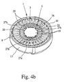
- Fig. 4a illustrates a possible constructional configuration of the sliding guide or of a control groove or control cam 26 preferably formed by the inner wall of the housing 13, in order to carry out the desired, preferably alternating axial movement of the reservoir 3 and the stepwise further rotation of the reservoir 3 by one receptacle 4.
- This combined movement is achieved in particular by the alternately axially and diagonally extending portions of the control cam 26, in which a projection of the reservoir 3 engages radially, for example.
- other radially inner and/or axial mechanisms are also possible.
- the outer engagement member 25 and the above-mentioned sliding guide form the transporting device 23 or components thereof.
- the sliding guide or the transporting mechanism is constructed in the manner of a ballpoint pen mechanism (axial movement back and forth leads to stepwise rotation).
- other constructional solutions are also possible which bring about, in particular, stepwise advancing or further rotation of the reservoir 3 by one receptacle 4 - particularly preferably by the axial movement and/or rotation of a gear component, such as the threaded sleeve 16.
- the transporting device 23 may have, alternatively or in addition to the sliding guide or control cam 26, a ratchet mechanism or locking latch mechanism 27 which allows an, in particular, stepwise advancing or further rotation of the reservoir 3 which is shown open or cut away in the drawing.
- the ratchet mechanism 27 is formed in particular between the outer engagement member 25 and the annular reservoir 3, so that these two are rotatable in one direction relative to one another by corresponding ratchet steps.
- the ratchet mechanism 27 has in the embodiment shown in particular a ratchet 27a in which a transporting arm 27b can engage. Particularly preferably radial locking engagement takes place. However, in principle it may also occur in the axial direction.
- the ratchet mechanism 27 is formed on the inside and/or encircling the reservoir 3.
- the transporting arm 27b can be moved by the delivery device 5, particularly the gear 15, particularly preferably in alternating manner.
- the transporting arm 27b is directly or indirectly connected to the threaded sleeve 16, particularly formed on the outer engagement member 25,
- the transporting arm 27b is biased elastically - particularly by its inherent elasticity towards the ratchet 27a to produce the desired locking engagement.
- Particularly preferably a plurality of transporting arms 27b are provided, to obtain the desired reliable stepwise movement of the reservoir 3 by back and forth movement or rotation of the cover 10 or threaded sleeve 16.
- the reservoir 3 and receptacles 4 there are various possibilities for the construction and configuration of the reservoir 3 and receptacles 4.
- it may be a blister arrangement, optionally combined with a carrier, or the like.
- the individual receptacles 4 are then formed by blister pouches, for example.
- the receptacles 4 are formed by inserts 28 which are accommodated in preferably separate, in particular radially extending guides or receiving chambers 29 of the reservoir 3.
- each insert 28 is preferably radially displaceable or movable.
- the receiving chambers 29 are preferably provided on the outer periphery of the reservoir 3 or the annular arrangement with openings 30 which are preferably closed, in particular sealed or otherwise closed off or covered, when not in use or in the state as supplied.
- openings 30 which are preferably closed, in particular sealed or otherwise closed off or covered, when not in use or in the state as supplied.
- a corresponding sealing film or the like is not shown in the Figures in the interests of simplicity.
- the receiving chambers 29 containing the inserts 28 are each hermetically sealed, particularly in fluid tight and possibly also gastight manner.
- the reservoir 3 is made in particular of diffusion proof plastics and/or is optionally provided with a diffusion proof outer packaging.
- Each insert 28 has a storage chamber 31 which contains the dose or formulation 2 of the particular insert 28 and in particular has been filled with the formulation 2 during the manufacture of the reservoir 3 or atomiser 1 at the factory end.
- Adjoining the storage chamber 31 is preferably a channel 32 in the insert 28 for delivering the formulation 2, which may if required merge into a nozzle (not shown) or form such a nozzle.
- the inserts 28 thus form with their storage chambers 31 the receptacles 4 for the formulation 2.
- the respective receptacle 4 is opened. In the embodiment shown this is preferably carried out at the delivery end by moving the respective insert 28 partly out of its receiving chamber 29 , particularly through the opening 30 and pushing a seal or the like (not shown) radially outwards through it. In this way the receiving chamber 29 or its opening 30 is opened up and the channel 32 is freed.
- the sealing foil or the like (not shown) which closes off the respective opening 30 is torn away from the insert 28 or another closure or covering member that closes off the opening 30 is displaced, opened, pushed out or otherwise removed from the insert 28.
- the preferred radial displacement of the insert 28 in order to open the respective receiving chamber 29 is carried out in the embodiment shown preferably by means of the connecting device 24 or the transporting device 23, in particular by having a finger 33 or other actuating member of the connecting device 24 penetrate in particular axially into the receiving chamber 29 in the region of the inner radial end of the respective insert 28 and in particular by a corresponding sliding surface (on the finger 33 and/or insert 28) performing the desired outward radial movement of the insert 28.
- the penetration of the finger 33 is possible for example because the reservoir 3 has a sufficiently thin wall or frangible point in the region of penetration.
- the reservoir 3 may also comprise an opening or the like which is sealed, covered or provided with a closure and can be opened or penetrated by the finger 33.
- Fig. 1 shows in section on the left-hand side a still closed receiving chamber 29 with an insert 28 which has not yet been radially pushed in.
- Fig. 2 shows the receiving chamber 29 which has already been opened on the outlet side, having the insert 28, which has already been moved radially, protruding from the opening 30.
- the connecting device 24 in this embodiment has a connecting element 34 for creating a fluidic connection with the respective receptacle 4 for supplying the delivery medium, in particular so that the delivery medium can be supplied, for example through a delivery channel 35 as shown by the delivery device 5 via the connecting element 32 of the respective receptacle 4 - i.e. the respective insert 28 or its storage chamber 31 - for delivery and in particular for atomisation of the respective dose of formulation.
- the fluidic connection is preferably also created by the axial movement of the reservoir 3 relative to the housing 13 or connecting element 34.
- the finger 33 first engages axially in the respective receiving chamber 29 in order to move the insert 28 which is to be used next in the radial direction.
- the connecting element 34 engages in the receiving chamber 29 and in the insert 28.
- the connecting element 34 is constructed in particular as a piercing element, for example in the form of a cannula or needle with a corresponding point, so as to assist in particular with the piercing or other penetration of the storage chamber 31 in order to create the desired fluidic connection.
- the fluidic connection for the delivery medium to the storage chamber 31 is provided and the delivery medium can be supplied to the storage chamber 31 for the expulsion of the formulation 2.
- the outer engagement member 25, the finger 33 and the connecting element 34 form the connecting device 24 or components thereof
- other constructional solutions are possible for opening or piercing the receptacles 4 one after another or as necessary on the supply side and/or on the outlet side and/or for connecting them to the delivery device 5 or for creating another fluidic connection, e.g. for the direct supply or intake of ambient air, and in particular for moving the relevant insert 28 preferably radially, but optionally also axially, for opening the respective openings 30 of the receiving chamber 29 and/or for connecting the storage chamber 31 in the insert 28 to the supply of delivery medium, in particular for inserting the connecting element 34 into the storage chamber 31.
- an axial movement leads to the opening, connecting or piercing through the connecting device connecting device 24, preferably at right angles to the direction of delivery 11 or the direction of conveying of the receptacles 4 or the direction of movement or rotation of the reservoir 3.
- axial connection or piercing is carried out in the embodiment shown.
- radial or other connection or piercing is also fundamentally possible, and this can also be effected if necessary by means of the axial movement provided or carried out by the gear 15.
- connection, opening, piercing and/or delivery 11 may run radially.
- the connecting device 24 - in particular like the delivery device 5 and/or transporting device 23 - may be actuated by opening and/or closing the cover 10 and/or may be actuated by the preferably common gear 15 or at least one axial movement.
- the transporting device 23 and/or the connecting device 24 are arranged inside the annular arrangement of the reservoir 3 or receptacles 4. This in turn contributes to a particularly compact structure for the atomiser 1 and in particular helps to minimise the axial height of the atomiser 1.
- the reservoir 3 is preferably rigid.
- the term "rigid" is to be taken to mean that the reservoir 3 or its receiving chambers 29 preferably form a sufficiently stable or well-defined holder and possibly guide for the inserts 28.
- other constructional solutions are possible.
- the insert 28 may be removed completely from the reservoir 3 for connecting the receptacle 4 or when opening the receiving chamber 29 or for delivering the respective dose.
- the reservoir 3 may also for example be constructed only as a blister pack or other package.
- Fig. 2 shows the atomiser 1 in the activated state. Ambient air is sucked into the pump chamber 6. The spring 14 is tensioned. The receptacle 4 selected for delivering the next dose has been opened and connected, the corresponding insert 28 has been pushed radially outwards and connected to the supply of delivery medium by means of the connecting element 34, in particular pierced by the latter.
- the actual delivery and in particular the atomisation of the formulation 2 or dose contained in the pierced receiving chamber 29 can only take place after a corresponding triggering or further actuation, for example after another or further actuation of the cover 10, but in particular as a result of the actuating element 21, which is preferably only moved axially outwards in this state, being actuated, particularly pressed axially inwards by a user or patient (not shown).
- the delivery medium in the pump chamber 6 is put under pressure and conveyed through the delivery channel 35 and the connecting element 34 into the adjoining storage chamber 31.
- the delivery medium continues to flow through the channel 32 and out of the insert 28, the formulation 2 contained in the storage chamber 31 being expelled at the same time.
- the resulting aerosol or spray cloud is emitted through the optional grid 9 through the mouthpiece 8, so that the user or patient can inhale the formulation 2 which has been emitted and in particular atomised.
- Fig. 5 shows the atomiser 1 in schematic section after inhalation, i.e. with the spring 14 relaxed, the receptacle 4 empty and the cover 10 still open.
- the cover 10 is closed again. This is done in particular in the opposite direction of rotation. Because of the coupling provided - in particular by means of the gear 15 - the inner engagement member 19 is moved back again in the axial direction into its starting position shown in Fig. 1 , while the spring store or the spring 14 is tensioned again and finally the operative connection or other axial connection between the engagement member 19 and the delivery device 5 or the spring store - particularly via the locking arm 20 - is re-established, so that the starting position shown in Fig. 1 with the spring 14 relaxed and with the desired retaining connection between the engagement member 19 and particularly the bellows 7 and/or the spring 14 is recreated. Moreover, the reservoir 3 is moved back into its axial starting position, i.e. pushed axially back in the opposite direction. In particular this releases the reservoir 3 from the finger 33 and from the connecting element 34.
- the advancing or further rotation of the reservoir 3 by one receptacle is preferably superimposed on the axial movement, and this always takes place during the up and down movement, i.e. during the opening and/or closing of the cover 10, when the connecting device 24 - particularly the fingers 33 and connecting element 34 thereof - is no longer engaging in the reservoir 3 but is allowing the desired rotary movement.
- the sliding guide or control cam 26 is therefore preferably designed so that the desired advance or further rotation of the reservoir 3 by one receptacle 4 takes place during only part of the axial movement.
- the proposed atomiser 1 can be operated very simply and intuitively. Essentially all that is needed to operate it is to open and close the cover 10. All the functions or processes envisaged are triggered or controlled thereby or take place automatically.
- actuation of the cover 10 when the atomiser 1 is constructed as an active atomiser 1, it only remains to trigger the actual delivery and atomisation after opening the cover 10. This is preferably done by actuating, particularly pressing, the actuating element 21.
- the actuating element 21 is preferably only actuatable, axially moved out and/or accessible once the atomiser 1 has been activated, i.e. once the cover 10 has been opened, simple intuitive operation is made possible and incorrect operation is ruled out.
- the actuating element 21 passes in particular through an opening in the cover 10.
- the actuating element 21 may be accessible, e.g. revealed by the cover 10, in the activated state of the atomiser 1.
- the atomiser 1 or the cover 10 can be closed again.
- the cover 10 is secured against closure as long as the actuating element 21 has not been actuated, i.e. in the embodiment shown is still in the axially extended position, or until the formulation 2 has been delivered from the receptacle 4 which has already been opened or connected up or pierced.
- Fig. 3 shows the proposed atomiser 1 in the opened or activated state.
- the cover 10 is thus rotated by about 160° to 180° relative to the closed transportation position shown in Fig. 1 .
- the cover 10 can preferably only be rotated in opposite directions to open and close it.
- a rotation stop 36 is provided which is visible from the outside in the embodiment shown and protrudes for example from the periphery or housing 13. This helps to ensure simple and intuitive operation of the atomiser 1, as the user intuitively grasps how far and in which direction the cover 10 has to be opened or closed.
- the atomiser 1 is constructed so that the rotation stop 36 forms a stop both for the cover 10 in the open state and also for the cover 10 in the closed state. Alternatively, separate projections or stops could also be provided for this purpose.
- the atomiser 1 or cover 10 also preferably comprises a locking device 37 shown in Fig. 4c (partial section through the atomiser 1 in the activated state) which ensures that the cover 10 can only ever be opened and closed alternately.
- a locking device 37 shown in Fig. 4c partial section through the atomiser 1 in the activated state
- at least one corresponding latch 38 or the like is provided for example between regions of the cover 10 and housing 13 arranged axially above or behind one another, providing the desired functionality.
- the atomiser 1 or the locking device 37 comprises a control ring 39 which is shown separately in perspective view in Fig. 4d .
- the control ring 39 is provided with teeth or a latch 38 on both of its axial or flat sides.
- the control ring 39 is rotatably guided in particular in an annular channel or the like in the atomiser 1 or the housing 37 thereof, as shown in Fig. 1 , 2 and 4c .
- Engaging in a latch 38 of the control ring 39 is a locking arm 40a on the housing side while engaging in the other latch 38 is a locking arm 40b on the cover side, as indicated in Fig. 4c .
- the latches 38 and locking arms 40a und 40b are matched to one another such that the cover 10 is initially only movable or rotatable in one direction relative to the housing 13, and hence rotation in the opposite direction is prevented by the locking device 37 or by locking arms 40a or 40b acting in the opposite direction.
- a plurality of locking arms 40a are provided on the housing 13, which engage in the associated latch 38 of the control ring 39 and allow the control ring 39 to rotate only in one direction relative to the atomiser 1 or housing 13.
- a number of locking arms 40b are preferably also arranged on the cover 10 or associated therewith and allow the control ring 39 to rotate in only one direction of rotation relative to the cover 10.
- Fig. 4e shows by way of example the locking of the control ring 39 against rotation relative to the housing 13. This locking is carried out in a corresponding or similar manner between the cover 10 and the control ring 39 and acts during the opposite movement of the cover 10 relative to the housing 13.
- At least one stop 40c strikes against at least one stop arm 40d, so that the rotation of the control ring 39 relative to the housing 13 which would otherwise be possible into the direction of rotation which is not blocked off by the locking arm 40a and its associated latch 38 is also blocked. This blocking by the stop arm 40d remains until the cover 10 moves into its end position.
- a control slope or sliding surface 40e formed on the cover 10 leads to a springing of the stop arm 40d, so that now the previously blocked stop 40c is freed and hence the cover 10 can be turned back relative to the control ring 39 and hence also rotated or moved in the opposite direction.
- another stop 40c of the control ring 39 comes to abut on a stop arm 40d arranged on the cover 10, thereby blocking the relative rotatability of the control ring 39 relative to the cover 10.
- the cover 10 can now only be rotated or moved together with the control ring 39 in the opposite direction until the other end position is reached.
- the cover 10 can only be fully opened or closed alternately, so as to ensure simple and intuitive operation or actuation and in particular to rule out incorrect operation.
- the atomiser 1 may also be constructed as a passive atomiser.
- the delivery device 5 and/or the energy store or spring store can be dispensed with.
- ambient air can be taken in by the action of breathing during inhalation, and this air is conveyed through the respective receptacle 4 - particularly the receiving chamber 29 and the channel openings 30 of the insert 28 in question - to the mouthpiece 8, so that the formulation 2 is delivered or expelled and atomised in the desired manner.
- the spring store may also be used independently of the delivery device 5 for example for advancing and/or opening or closing the receptacles 4, particularly for driving and/or actuating the transporting device 23 and/or the conveying device 24.
- the actuating element 21 and an actuation required in addition to the movement of the cover 10 - i.e. an additional triggering of the actual release and atomisation of the formulation 2 - may be omitted. Rather, it is then preferably sufficient to open the cover 10 in order to activate the atomiser 1, so that the next receptacle 4 is ready directly with its dose or formulation 2 for inhalation and inhalation can take place immediately.
- the mouthpiece 8 is preferably of fixed construction and/or radially aligned and/or preferably formed directly on the housing 13. This results in a simple and compact structure of the atomiser 1 with, in particular, an at least substantially smooth outer contour.
- the mouthpiece 8 may also theoretically be movable, e.g. foldable, slidable, telescopically extendable or movable in some other way.
- the mouthpiece 8 may also be aligned or arranged in a different direction, e.g. diagonally or axially, for delivering the formulation 2 or the aerosol.
- the proposed atomiser 1 preferably additionally comprises a counter (not shown).
- the proposed atomiser 1 preferably operates purely mechanically.
- the proposed atomiser 1 is preferably made up at least essentially of only plastics components or parts or made at least essentially only of plastics. Only the spring 14 and optionally the grid 13 may be made of metal, if necessary.
- the manual actuation of the active delivery and atomisation of the formulation 2, which is carried out in the first embodiment by pressing the actuating element 21, in particular, may also be omitted.
- an actuation controlled by breathing in is preferably provided.
- the holding connection between the inner engagement member 19 on the one hand and the biased spring 14 or the bellows 7, another conveying or pumping element or the like, on the other hand can be undone in order to enable the desired delivery and particularly the atomisation of the formulation 2 to take place virtually automatically during inhalation, namely by means of the energy stored in the energy store or spring store.
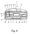
- Fig. 6 and 7 show schematic views of a second embodiment of the proposed atomiser 1.
- Fig. 6 shows the atomiser 1 in the closed position with the receptacle 4 not yet pierced.
- Fig. 7 shows the atomiser 1 in the activated state with the receptacle 4 opened or pierced.
- the reservoir 3 is not axially movable, in contrast to the first embodiment.
- the connecting device 24 is preferably axially slidable or movable.
- the reservoir 3 is held by a rotatable inner part 41.
- the connecting device 24 (at least the connecting element 34 thereof and preferably the fingers 33 thereof) is mounted on a carrier 42, which is axially movable but not rotatable.
- the carrier 42 is in turn preferably axially movable by opening and/or closing the cover 10, particularly by means of the gear 15 which is not shown in detail here.
- the carrier 42 preferably has axially operating teeth 43, e.g. with sawtooth-like sliding surfaces or the like, which cooperate with complementary or corresponding mating teeth 44 provided or formed on the inner part 41 and in particular engage therein such that the axial movement of the carrier 42 causes a defined, stepwise further rotation of the inner part 41 with the reservoir 3.
- axially operating teeth 43 e.g. with sawtooth-like sliding surfaces or the like, which cooperate with complementary or corresponding mating teeth 44 provided or formed on the inner part 41 and in particular engage therein such that the axial movement of the carrier 42 causes a defined, stepwise further rotation of the inner part 41 with the reservoir 3.
- the carrier 42 fits over or around the inner part with the reservoir 3 preferably peripherally and in particular in such a manner that the carrier 42 extends from an end face of the inner part 41 around the outside of the reservoir 43 to the other end face of the reservoir 3 and radially back inwards to an inner edge on which the preferably axial teeth 43 are formed.
- the carrier 42 has a peripheral opening 45 which at least in the activated state lies on an extension of the particular receptacle 4 which has been opened or pierced, or of the radially advanced insert 28, such that the delivery of the formulation 2 is made possible and not obstructed.
- Fig. 8 shows in schematic section a third embodiment of the proposed atomiser 1 in the opened, activated state.
- the third embodiment largely corresponds to the second embodiment, although the connecting device 24 does not engage, as in the second embodiment, from the flat side covered by an annular flange of the inner part 41, but from the opposite flat side into the reservoir 3 - particularly with the finger 33 and the connecting element 34.
- Fig. 9 shows in schematic view a fourth embodiment of the proposed atomiser 1 in the transportation position or locked state.
- the cover 10 here is in the form of a cap.
- the pivot axis of the cover 10 is eccentrically arranged or formed, particularly in the region of the periphery or edge of the atomiser 1.
- the cover 10 essentially only covers the mouthpiece 8.
- the opening and/or closing of the cover 10 is preferably not coupled with the other functions of the atomiser 1.
- the atomiser 1 has a release mechanism 46 which is constructed in particular as a peripherally movable slide.
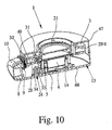
- Fig. 10 shows in schematic section the atomiser 1 in the unlocked state.
- the atomiser 1 has two preferably external housing parts, particularly an upper housing part 47 and a lower housing part 48 which are movable axially towards one another.
- the housing parts 47, 48 are biased away from one another preferably by a plurality of spring elements 49, so that in the unlocked and non-compressed state the upper housing part 47 is axially raised relative to the lower housing part 48, as shown in Fig. 10 .
- the two housing parts 47, 48 are movable axially together counter to the force of the spring elements 49. In the axially compressed state the two housing parts 47, 48 are latchable together, in particular. This latching can be released by actuating the release mechanism 46.
- the upper housing part 47 is automatically moved axially away from the lower housing part 48 by the spring elements 49.
- This movement away or lifting movement causes actuation of the delivery device 5, namely enlargement of the pump chamber 6 and an intake of ambient air.
- the spring 14 associated with the delivery device 5, particularly its bellows 7, is axially tensioned or compressed thereby.
- the spring elements 21 accordingly have a greater spring force than the spring 14.
- the axial lifting movement causes the reservoir 3 to be axially moved and separated from the connecting device 24 (not shown in detail).
- the two housing parts 47, 48 have to be manually pushed together axially counter to the force of the spring elements 49 by a user (not shown).
- the reservoir 3 is further rotated by one receptacle 4.
- the further rotation or advancing of the reservoir 3 is preferably carried out in turn by slidable controlling of the transporting device 23 or the like.
- the receptacle 4 that has been rotated into the delivery position is then opened and connected to the conveying device, preferably in turn through the connecting device 24 (not shown here).
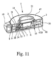
- Fig. 11 shows the activated state of the atomiser 1 that results after the pushing together, with the housing parts 47, 48 latched or locked together, and with the axially protruding actuating element 21.
- the blocking of the spring 14 is released, so that the spring 14 can relax axially and thereby actuate the delivery device 5, particularly pressurise the air contained in the pump chamber 6, so that this air is conveyed through the attached receptacle 4 and delivers the formulation 2 in the desired manner through the mouthpiece 8.
- the fourth embodiment also allows very simple intuitive operation. Improper operation is prevented in particular by suitable blocking means.
- Fig. 12 to 14 show a fifth embodiment of the proposed atomiser 1 in various states corresponding to those shown in Fig. 9 to 11 .
- the fifth embodiment differs essentially from the fourth embodiment in that the direction of opening, piercing and/or displacement and/or alignment of the receptacles 4 or inserts 28 extend at least substantially axially or parallel, but not radially relative to the axis 12 or the annular arrangement of the reservoir 3 or of the receptacles 4.
- the mouthpiece 8 is accordingly arranged or formed above the reservoir 3 on the side of the atomiser 1 or housing 13 - in this case the upper housing part 47, in particular - while the mouthpiece 8 protrudes or projects substantially at right angles or perpendicularly to the flat side of the atomiser 1.
- Fig. 15 shows in schematic section a sixth embodiment of the proposed atomiser 1 in the transportation position.
- the sixth embodiment resembles the fourth embodiment in particular, in principle. However, unlike the previous embodiments the sixth embodiment does not have a delivery device 5. Rather, it is a passive atomiser 1.
- the two housing parts 47 and 48 which can be moved axially away from each other are latched or locked together, particularly by at least one snap-fit hook 50 or the like.
- the at least one snap-fit hook 50 may preferably engage behind an annular shoulder 51 or the like on the other housing part 47, 48, in order to form an interlocking holding connection between the two housing parts 47, 48 in the axial direction in the locked position.
- a plurality of spring elements 49 are provided.
- a central spring element 49 is provided which is formed in particular by a central helical spring which braces the two housing parts 47 and 48 apart,
- the at least one snap-fit hook 50 or the like is sprung out, i.e. the latching of the two housing parts 47 and 48 is undone, so that the two housing parts 47 and 48 can move axially away from one another, as shown in Fig. 16 .
- the reservoir 3 is preferably rotated further by one receptacle 4.
- the movement away or axial movement takes place automatically as a result of the spring force of the spring element 49.
- This axial movement is preferably in turn converted by a gear or teeth, sliding guide or the like (not shown) into the desired, stepwise rotary movement of the reservoir 3.
- the ballpoint pen mechanism mentioned earlier can come into play here, too.
- the connecting element 34 of the connecting device 24 can be detached from the receptacle 4 which has already been emptied during the last delivery.
- the two housing parts 47, 48 are pressed manually together counter to the force of the spring element 49.
- the spring element 49 is tensioned again and the next receptacle 4 is connected or opened by the connecting device 24, particularly the connecting element 34 thereof.
- the at least one snap-fit hook 50 automatically locks the two housing parts 47 and 48 together again in the pushed-together end position, as shown in Fig. 15 .
- the receptacle 4 in question is preferably also axially opened or pierced.
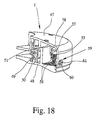
- the reservoir 3 is constructed here as a blister ring (not shown) comprising a plurality of blister pouches or, in particular, as an annular carrier 55 with a plurality of preferably axially open recesses 56 for receiving the blister ring (not shown) or blister pouches, as indicated in particular in the detail shown in Fig. 18 .
- the reservoir 3 is formed directly by the lower housing part 48 or is in particular fixedly connected thereto, in the embodiment shown.
- the sixth embodiment preferably comprises a blocking device 57 which blocks further actuation, particularly further opening of the atomiser 1 or movement of the housing parts 47 and 48 after all the receptacles 4 have been used or emptied.
- the blocking device 57 is for example formed like a hook on the reservoir 3, an associated inner part 41 or the annular carrier 55 and when the blocking position is reached, for example, engages in an abutment 58 formed on the upper housing part 47 so that the two housing parts 47 and 48 can no longer be moved axially apart. This blocking is preferably irreversible as well.
- Fig. 18 shows the housing parts in the position where they are still apart from each other.
- the sixth embodiment preferably comprises a counter 59 which in the embodiment shown preferably comprises a corresponding scale 60 on the reservoir 3, particularly on the outer periphery of the reservoir 3 or lower housing part 48, and a corresponding window 61 in the housing 13, particularly the upper housing part 47.
- the relative rotational position of the reservoir 3 corresponds to the number of receptacles 4 which have already been used or are still available for use.
- the scale 60 can indicate the number of receptacles 4 which are still available for use or have already been used.
- Fig. 19 shows the counter 59 in a cut-away side view.
- Fig. 20 shows in a view corresponding to Fig. 19 the atomiser 1 in the unlocked state, i.e. with the upper housing part 47 axially raised.
- the reservoir 3 has preferably been moved axially relative to the window 61 so that the scale 60 is not visible. Instead, preferably a symbol, particularly an arrow or the like, is indicated, to show the user how to operate it, namely by pressing the two housing parts 47 and 48 together as required.
- the counter serves not only to count but also has another function and assists with the operation of the proposed atomiser 1.
- the atomiser 1 may have a central or axial recess 62 in the housing 13 or upper housing part 47, as indicated in Fig. 15 and 16 .
- This recess 62 may be used for additional functions or devices.
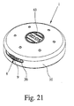
- Fig. 21 shows an alternative embodiment of the atomiser 1 with a clock 63 or with a time measuring device.
- the clock 63 is preferably installed in the recess or otherwise integrated in the atomiser 1 or its housing 13.
- the clock 63 is in particular constructed so that a preferably optical, acoustic and/or vibratory signal can be emitted to remind the user to use the atomiser 1.
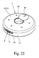
- Fig. 22 shows another alternative embodiment of the atomiser 1 with a closable chamber or other receptacle for medicaments or the like (not shown).
- the recess 62 is constructed to accommodate medicaments or the like and can be closed off for example by a lid 64 or other closure.
- Fig. 23 shows in schematic section an eighth embodiment of the proposed atomiser 1 in the transportation position, namely with the cover 10 closed.
- the eighth embodiment is a passive atomiser 1, like the one in the seventh embodiment.
- the opening and closing and actuating of the atomiser 1 by rotating or pivoting the cover 10 corresponds however, in principle, to the first to third embodiments.
- the reservoir 3 and connecting device 24 are constructed essentially as in the seventh embodiment.
- the connecting device 24 or the connecting element 34 thereof is axially movable by the opening and closing of the cover 10 by means of the gear (not shown in detail). In the transportation position, the connecting device 24 or the connecting element 34 thereof are moved axially away from the reservoir 3.
- Fig. 24 shows this activated state in schematic section.
- a current of air is produced which is passed through the connecting element 34 through the receptacle 4 or the storage chamber 31, such as a blister pouch or the like, and in this way the formulation 2 contained in the receptacle 4 is expelled and delivered through the adjoining mouthpiece 8.
- the inlet 52 and outlet 53 are preferably formed by a common component, particularly the one-piece connecting element 34.
- the connecting element 34 preferably also has an outlet channel 65 adjacent to the outlet 53 and widening out in a funnel shape or other suitable manner, in particular.
- Fig. 25 shows a schematic view which illustrates the transporting device 23 of the atomiser 1 according to the eighth embodiment.
- axial teeth 43 on the reservoir side and axially movable mating teeth 44 on the housing side - particularly together with the connecting device 24 - cooperate so as to achieve the desired stepwise advancing or further rotation of the reservoir 3 by one receptacle 4, with each axial movement of the mating teeth 44 relative to the teeth 43 associated with the opening of the cover 10.
- the ballpoint pen principle mentioned previously comes into play again.
- the counter 59 is preferably arranged on the flat side or axial side of the atomiser 1, particularly with the window 61 being formed in the cover 10 and in the housing 13, so that the current status of the counter can preferably always be read off even when the cover 10 is closed.
- the reservoir 3 is again preferably provided with an annular carrier 55 for holding a blister arrangement, particularly a blister ring or the like.
- a reservoir 3 with inserts 28 for forming the receptacles 4 - may be used here.
- the eighth embodiment allows particularly easy operation as all that is required is to open the cover 10 in order to activate the atomiser 1, i.e. prepare it for atomisation or inhalation. Even after atomisation or inhalation, no other additional operations are required. Rather, it is necessary only to close the atomiser 1 or cover 10.
- the connecting device 24 or its connecting element 34 is moved axially away from the reservoir 3 or the receptacle 4 which was opened last, so that the transportation position shown in Fig. 23 is resumed.
- Fig. 26 shows a highly schematic rudimentary representation of the concept of a ninth embodiment of the proposed atomiser 1.
- the ninth embodiment relates to an active atomiser 1 having a delivery device 5 and an energy or spring store which are preferably arranged within the annular arrangement of the reservoir 3 or the receptacles 4, which are merely indicated by receiving chambers 29 in Fig. 26 .
- the delivery device 5 is again preferably constructed as a pump and is provided, in particular, with the bellows 7 which are preferably movable thereon in a radial direction for pumping, particularly are extendable and collapsible or compressible.
- the spring store or spring 14 is preferably arranged in this pumping direction behind the bellows 7, particularly on the side remote from the connecting device 24.
- Fig. 26 shows the spring store or the spring 14 in the biased state with the bellows 7 extended. In this state ambient air has already been taken in by the delivery device 5 or the bellows 7.
- the delivery device 5 with the spring store is preferably movable in the manner of a sled.
- the delivery device 5 with the connecting device 24 or the connecting element 34 is first of all advanced radially so that the next receptacle 4 or the next insert 28 is radially pierced or connected to the delivery device 5 and moved radially outwards. This state is shown in the schematic representation in Fig. 27 . Then actuation takes place.
- the bellows 7 By relaxing the spring 14 in the radial direction the bellows 7 is compressed and the air contained therein flows through the connecting element 34 and the attached receptacle 4 - particularly the attached insert 28 - as a result of which the formulation 2 contained in the receptacle 4 or in the insert 28 is expelled. Then the delivery device 5 with the connecting device 24 can be radially withdrawn again. In addition, the spring 14 is biased once again and secured or latched in the biased position.
- next receptacle 4 or insert 28 can be pierced and, in particular, pushed radially outwardly to open its respective sealing.
- the spring 24 remains compressed or tensioned and the bellows 7 remains extended.
- the spring 14 is released to compress the bellows 7, i.e. to actuate the pump, so that the compressed delivery medium, i.e. air, is forced through the insert 28 to deliver or discharge or atomise or de-agglomerate the respective dose of formulation 2 and to generate the desired spray of the formulation 2.
- the compressed delivery medium i.e. air
- Part of the radial movement is preferably also used to index or move the reservoir 3 to the next receptegle 4, i.e. to actuate the transporting device 23.
- the transporting device 23 in the ninth embodiment preferably engages internally on the reservoir 3, particularly via a pinion 66 which preferably engages in inner teeth 67 of the reservoir 3.
- connecting device 24 and the pump 5 preferably form a unit or are interconnected.
- the connecting element 34 is connected to the sled and/or pump 5 and/or bellows 7.
- the receptacles 4 / receiving chambers 29 form preferably separate parts that are mounted on the preferably ring-like carrier 55, in particularly in a form-fit and/or rigid manner.
- the receiving chambers 29 or receptacles 4 are preferably separately or individually sealed by respective sealings and/or preferably at least on its outer circumferential periphery (not shown in Fig. 26 and 27 ).
- Fig. 28 shows, in a similarly very schematic, rudimentary representation, a tenth embodiment of the proposed atomiser 1.
- the tenth embodiment is related to the ninth embodiment and in particular is similar to it, most preferably with respect to the arrangement and/or function of the delivery device 5 and connecting device 24, and therefore no explanation of these is required.
- Fig. 29 shows the atomiser 1 according to the tenth embodiment in schematic section, in contrast to Fig. 28 with the housing 13 and the preferably rotatable or pivot able cover 10.
- the tenth embodiment allows a pivoting or rotary movement, particularly of the cover 10, to be converted into a linear and/or radial movement in order to actuate the delivery device 5 and/or connecting device 24, most preferably in order to move the connecting element 34.
- a sliding and/or automatically geared coupling or control is obtained.
- the atomiser 1 has at least one control element 68 which is constructed in particular in a manner of a disc (cf. Fig. 28 ).
- the control element 68 is preferably rotationally coupled to the cover 10 (in the embodiment shown via an axial engagement 69 as indicated in Fig. 29 ) or is formed by the cover element 10, for example.
- control element 68 forms a sliding guide or a number of sliding guides in order to actuate in particular both the delivery device 5 and the connecting device 24 or its connecting element 34 in the desired or necessary manner.
- control elements 68, sliding guides and/or other geared connections to control and actuate the delivery device 5 on the one hand and the connecting device 24 or its connecting element 34 on the other hand and/or for different sections of the movements.
- a first control cam or sliding guide 70 is provided for preferably linear or radial movement of the connecting device 24 or of the slide 79 formed by the delivery device 5 and/or connecting device 24.
- a first engaging element 71 engages in the first sliding guide 70.
- the first engaging element 71 is rigidly connected to the connecting device 24 or its connecting element 34, directly or indirectly.
- the first sliding guide 70 is shown in Fig. 28 as an opening. However, it may also be a recess or groove or the like, in particular, as shown in Fig. 29 .
- the path of the first sliding guide 70 determines the geared coupling or the dependency of the linear movement which may also extend circumferentially and/or radially, on the rotary movement.
- the first sliding guide 70 comprises a first section 72, particularly extending over a circumference, an adjoining second, preferably linear section 73 and/or one which has a radial component, and/or a third section 74 which in particular again extends over a circumference.
- the delivery device 5 or the spring store or the spring 14 was preferably already under tension. Therefore the actuating element 21 can now be actuated, so that the formulation 2 is delivered, particularly by deflecting a locking arm 20 and thereby releasing the spring 14 or the bellows 7 and compressing the pump chamber 6, as a result of which the formulation 2 is expelled or delivered and in particular atomised by the delivery medium in the desired manner, as explained previously.
- the cover 10 or the control element 68 preferably serves simultaneously to actuate the delivery device 5, particularly to bias the spring store or the spring 14.
- the control element 68 comprises for this purpose a second control cam or sliding guide 75, with which a second engaging element 76 cooperates, in particular, which in the embodiment shown is associated with the delivery device 5 or spring store or spring 14 , particularly a radially or linearly movable abutment 77 of the spring 14, or is firmly connected thereto, either directly or indirectly.
- the abutment 77 is guided slidably or in the manner of a sled on the delivery device 5 or on the slide 79, which in turn is slidable in the manner of a sled in the direction of movement - in this case the radial direction - and in particular holds or carries the connecting device 24 or the connecting element 34 thereof.
- Fig. 29 shows the spring 14 in the biased position (in this case the compressed state).
- the abutment 77 is held in the biased position by means of at least the locking arm 20.
- the second sliding guide 75 is preferably constructed in the embodiment shown such that in the closed position or transportation position the spring store or spring 14 is secured against unintentional relaxation, in particular by a shoulder 78 which blocks radial movement of the second engagement 76 in this position.
- the locking arm 20 When the actuating element 21 is actuated the locking arm 20 is deflected out or the locking engagement is undone and the spring store or spring 14 is relaxed or the delivery device 5 is triggered.
- the spring 14 then compresses the bellows 7 or the pump chamber 6 in the manner described previously - in the embodiment shown - in linear fashion or in the radial direction. Accordingly the formulation 2 (not shown in Fig. 28 and 29 ) is then delivered and in particular atomised from the connected receptacle 4 or the connected insert 28, as already explained with reference to the other embodiments.
- the second engaging element 76 moves, in particular, towards the centre of the atomiser 1 or control element 68 or towards the rotation axis of the cover 10, and optionally beyond.
- the second sliding guide 75 is correspondingly freely cut to allow this movement. In the embodiment shown this movement extends essentially along a radial section 80 of the second sliding guide 75.
- control element 68 is turned back or the spring store or spring 14 is put under tension again.
- the abutment 77 is held back via the second engaging element 76 over a certain section of the opposing radial movement of the slide 79 or first engaging element 71 by a retaining section 81 of the second sliding guide 75, so that in this section of the movement the spring store or spring 14 is biased again and the bellows 7 is again extended in particular until latching takes place by means of the locking arm 20.
- the connecting element 34 is preferably at least partly withdrawn at the same time from the attached receptacle 4 or the attached insert 28.
- Fig. 29 in turn shows the preferably annular reservoir 3 in purely schematic form. In connection with this, reference may be made in particular to the remarks relating to the other embodiments.
- the transporting device 23 not shown in the tenth embodiment can preferably be actuated in order to advance the reservoir 3 to the next receptacle 4.
- This is done in particular by means of a corresponding or suitable geared coupling or the like.
- axial displacement of the reservoir 3 may be carried out for this purpose, as explained hereinbefore, the advance being carried out in the circumferential direction or in particular by means of a control cam 26 or the like preferably on the housing side.
- a geared coupling particularly by means of a thread, may be used as in the other embodiments.
- atomiser is preferably to be interpreted very broadly so as to include other delivery devices, dispensers or the like, while the formulation 2 or other medium or fluid need only be atomised if required and may optionally also be delivered in a different form.
- compositions of the preferably medicinal formulation 2 are listed below. As already mentioned, they are in particular powders or liquids in the broadest sense. Particularly preferably the formulation 2 contains the following:
- W is a pharmacologically active substance and is selected (for example) from among the betamimetics, anticholinergics, corticosteroids, PDE4-inhibitors, LTD4-antagonists, EGFR-inhibitors, dopamine agonists, H1-antihistamines, PAF-antagonists and PI3-kinase inhibitors.
- W is a pharmacologically active substance and is selected (for example) from among the betamimetics, anticholinergics, corticosteroids, PDE4-inhibitors, LTD4-antagonists, EGFR-inhibitors, dopamine agonists, H1-antihistamines, PAF-antagonists and PI3-kinase inhibitors.
- double or triple combinations of W may be combined and used in the device according to the invention. Combinations of W might be, for example:
- the compounds used as betamimetics are preferably compounds selected from among albuterol, arformoterol, bambuterol, bitolterol, broxaterol, carbuterol, clenbuterol, fenoterol, formoterol, hexoprenaline, ibuterol, isoetharine, isoprenaline, levosalbutamol, mabuterol, meluadrine, metaproterenol, orciprenaline, pirbuterol, procaterol, reproterol, rimiterol, ritodrine, salmefamol, salmeterol, soterenol, sulphonterol, terbutaline, tiaramide, tolubuterol, zinterol, CHF-1035, HOKU-81, KUL-1248 and
- the anticholinergics used are preferably compounds selected from among the tiotropium salts, preferably the bromide salt, oxitropium salts, preferably the bromide salt, flutropium salts, preferably the bromide salt, ipratropium salts, preferably the bromide salt, glycopyrronium salts, preferably the bromide salt, trospium salts, preferably the chloride salt, tolterodine.
- the cations are the pharmacologically active constituents.
- the above-mentioned salts may preferably contain the chloride, bromide, iodide, sulphate, phosphate, methanesulphonate, nitrate, maleate, acetate, citrate, fumarate, tartrate, oxalate, succinate, benzoate or p-toluenesulphonate, while chloride, bromide, iodide, sulphate, methanesulphonate or p-toluenesulphonate are preferred as counter-ions.
- the chlorides, bromides, iodides and methanesulphonates are particularly preferred.
- X - denotes an anion with a single negative charge, preferably an anion selected from among the fluoride, chloride, bromide, iodide, sulphate, phosphate, methanesulphonate, nitrate, maleate, acetate, citrate, fumarate, tartrate, oxalate, succinate, benzoate and p-toluenesulphonate, preferably an anion with a single negative charge, particularly preferably an anion selected from among the fluoride, chloride, bromide, methanesulphonate and p-toluenesulphonate, particularly preferably bromide, optionally in the form of the racemates, enantiomers or hydrates thereof.
- corticosteroids it is preferable to use compounds selected from among beclomethasone, betamethasone, budesonide, butixocort, ciclesonide, deflazacort, dexamethasone, etiprednol, flunisolide, fluticasone, loteprednol, mometasone, prednisolone, prednisone, rofleponide, triamcinolone, RPR-106541, NS-126, ST-26 and
- PDE4-inhibitors which may be used are preferably compounds selected from among enprofyllin, theophyllin, roflumilast, ariflo (cilomilast), tofimilast, pumafentrin, lirimilast, arofyllin, atizoram, D-4418, Bay-198004, BY343, CP-325.366, D-4396 (Sch-351591), AWD-12-281 (GW-842470), NCS-613, CDP-840, D-4418, PD-168787, T-440, T-2585, V-11294A, Cl-1018, CDC-801, CDC-3052, D-22888, YM-58997, Z-15370 and
- the LTD4-antagonists used are preferably compounds selected from among montelukast, pranlukast, zafirlukast, MCC-847 (ZD-3523), MN-001, MEN-91507 (LM-1507), VUF-5078, VUF-K-8707, L-733321 and
- EGFR-inhibitors which may be used are preferably compounds selected from among cetuximab, trastuzumab, ABX-EGF, Mab ICR-62 and
- the dopamine agonists used are preferably compounds selected from among bromocriptin, cabergoline, alpha-dihydroergocryptine, lisuride, pergolide, pramipexol, roxindol, ropinirol, talipexol, tergurid and viozan, optionally in the form of the racemates, enantiomers, diastereomers thereof and optionally in the form of the pharmacologically acceptable acid addition salts, solvates or hydrates thereof.
- the acid addition salts of the betamimetics are preferably selected from among the hydrochloride, hydrobromide, hydriodide, hydrosulphate, hydrophosphate, hydromethanesulphonate, hydronitrate, hydromaleate, hydroacetate, hydrocitrate, hydrofumarate, hydrotartrate, hydrooxalate, hydrosuccinate, hydrobenzoate and hydro-p-toluenesulphonate.
- H1-Antihistamines which may be used are preferably compounds selected from among epinastine, cetirizine, azelastine, fexofenadine, levocabastine, loratadine, mizolastine, ketotifen, emedastine, dimetindene, clemastine, bamipine, cexchlorpheniramine, pheniramine, doxylamine, chlorophenoxamine, dimenhydrinate, diphenhydramine, promethazine, ebastine, desloratidine and meclozine, optionally in the form of the racemates, enantiomers, diastereomers thereof and optionally in the form of the pharmacologically acceptable acid addition salts, solvates or hydrates thereof.
- the acid addition salts of the betamimetics are preferably selected from among the hydrochloride, hydrobromide, hydriodide, hydrosulphate, hydrophosphate, hydromethanesulphonate, hydronitrate, hydromaleate, hydroacetate, hydrocitrate, hydrofumarate, hydrotartrate, hydroxalate, hydrosuccinate, hydrobenzoate and hydro-p-toluenesulphonate.
- inhalable macromolecules as disclosed in EP 1 003 478 A1 or CA 2297174 A1 .
- the compounds may come from the groups of ergot alkaloid derivatives, the triptans, the CGRP-inhibitors, the phosphodiesterase-V inhibitors, optionally in the form of the racemates, enantiomers or diastereomers thereof, optionally in the form of the pharmacologically acceptable acid addition salts, the solvates and/or hydrates thereof.
- Examples of ergot alkaloid derivatives are dihydroezgotamine and ergotamine.
Abstract
Description
- The present invention relates to an atomiser according to the preamble of
claims 1. - The present invention relates in particular to the delivery and atomisation of a formulation for inhalation or for other medical or therapeutic purposes. Particularly preferably the present invention relates to the delivery of medical, pharmaceutical and/or therapeutic formulations which in particular contain or consist of at least one active substance.
- The present invention relates in particular to an inhaler. During atomisation an aerosol or a spray cloud is produced having, particularly for inhalation, very fine, solid and/or liquid particles, preferably in the range from 1 to 10 µm.
- The formulation is preferably a powder. Particularly preferably the invention therefore relates to a powder inhaler. The term "formulation" according to the present invention preferably also includes liquids, however, while the term "liquid" is to be understood in a broader sense as including inter alia solutions, suspensions, suslutions (mixture of solution and suspension), dispersions, mixtures thereof or the like.
- The specification that follows is directed primarily to the delivery and atomisation of a powdered formulation or to a powder inhaler, even if the invention is not restricted thereto, but may also be used, in particular, for other inhalers, atomisers or dispensers.
- The present invention relates in particular to an atomiser with a pre-metered formulation. In particular the individual doses are contained in separate receptacles such as chambers, blister pouches, inserts, capsules or the like, and can be individually taken out and atomised.
- Basically, there are passive and active atomisers. In the passive type the formulation is expelled through the air current produced by the user on inhaling or breathing in. In the active type the formulation is expelled independently of the breathing in during inhaling, and the delivery can be triggered by the inhalation process - in particular by so-called breath triggering. In particular a current of a delivery medium such as air or some other gas is generated by the atomiser or inhaler itself in order to deliver the formulation. For this purpose the atomiser has a delivery device such as an air pump or a pressurised gas container. The advantage of the active type over the passive type is that in the active type a very easily reproducible delivery and atomisation of the formulation can be achieved independently of the user.
-
EP 0 950 423 B1 -
EP 1 132 104 B1 -
WO 91/06333 A1 -
US 5,533,502 A discloses a passive powder inhaler having an annular reservoir, particularly a blister, having a plurality of receptacles for powder. The reservoir is rotatably held in the inhaler by a carrier. The carrier can be rotated by means of an axially protruding knob to select the next receptacle and can be moved axially in order to pierce the receptacle. However, this does not allow easy operation. In fact, the user has to hold the knob or carrier in the axially displaced state during inhalation. After being released the carrier with the reservoir returns to its axial starting position away from the piercing elements by the effect of spring force. -
WO 2005/037353 A1 discloses a passive inhaler with a strip of blisters which can be punctured by means of a pivotable actuator. The actuator comprises a mouthpiece and means for puncturing blisters. The blisterstrip can be advanced by pivoting the actuator. In one embodiment, the actuator is coupled to a cap covering the mouthpiece so that a blister is pierced when the cap is opened and indexed to move the next unused blister into position aperture in the housing when the cap is closed. The actuator is lifted when is the cap is closed so that a compact structure can not be achieved. If the actuator is not lifted, the next blister would be punctured due to the advancing of the blister strip when closing the cap. - Object of the present invention is to provide an atomiser which can be operated very simply, particularly intuitively, while being simple and inexpensive in its construction, and which allows or has a compact structure, particularly a low overall height.
- The above object is achieved by an atomiser according to
claim 1. Further features are subject of the subclaims. - According to a first aspect of the present invention which can also be implemented independently, the atomiser has a gear or transmission for producing, from the opening and/or closing movement of the cover, a preferably axial movement to open the next receptacle, for displacing and/or advancing the store by one receptacle, for tensioning a spring store, for actuating a delivery device, particularly for taking in air, and/or for actuating a counter or other device of the atomiser. This results in a simple, compact construction, particularly when the gear or transmission is arranged within an annular arrangement of the reservoir or receptacles.
- According to a second aspect of the present invention, the covering of the mouthpiece of the atomiser is coupled to a delivery device such as a pump and/or to an energy store such as a spring store such that opening and/or closing the cover actuates the delivery device and/or generates energy and this is stored in the energy store. In particular, when the cover is opened, a delivery medium, preferably air, is taken in by the delivery device and/or placed under pressure. Alternatively or additionally, energy produced by opening and/or closing the cover is preferably stored by tensioning the spring store. Thus, a very simple and in particular intuitive operation of the atomiser is made possible. Furthermore, this enables the construction to be kept particularly simple and hence also inexpensive. For example, there may be no need to have a separate actuating element for operating the delivery device or pump and/or for tensioning the spring store or the like.
- In a third aspect of the present invention which can also be implemented independently, the atomiser has a closable chamber for accommodating medicaments independently of the reservoir. This results in a simple, compact construction with increased medicament capacity.
- Further aspects, features, properties and advantages of the present invention will become apparent from the claims and the following description of preferred embodiments, with reference to the drawings, wherein:
- Fig. 1
- shows a schematic section through a proposed atomiser accord- ing to a first embodiment in a transportation position;
- Fig. 2
- shows a schematic section through the atomiser according to
Fig. 1 in an activated state; - Fig. 3
- shows a perspective view of the atomiser in the opened or acti- vated state;
- Fig. 4a
- shows a schematic view of a sliding guide in the atomiser ac- cording to
Fig. 1 ; - Fig. 4b
- shows a schematic view of the open or cutaway atomiser accord- ing to
Fig. 1 with a ratchet mechanism; - Fig. 4c
- shows a schematic section through the atomiser according to
Fig. 1 with a locking device; - Fig. 4d
- shows a perspective view of a control ring of the locking device according to
Fig. 4c ; - Fig. 4e
- shows another schematic section through the atomiser with the locking device according to
Fig. 4c ; - Fig. 5
- shows a schematic section through the
atomiser 1 according toFig. 1 after a delivery or atomisation; - Fig. 6
- shows a schematic section through a proposed atomiser accord- ing to a second embodiment in the transportation position;
- Fig. 7
- shows a schematic section through the atomiser according to
Fig. 6 in the activated or opened state; - Fig. 8
- shows a schematic section through a proposed atomiser accord- ing to a third embodiment in the opened or activated state;
- Fig. 9
- shows a schematic view of a proposed
atomiser 1 according to a fourth embodiment in the transportation position; - Fig. 10
- shows a schematic section through the atomiser according to
Fig. 9 in the unlatched state; - Fig. 11
- shows a schematic section through the atomiser according to
Fig. 9 in the activated, pressed-together state; - Fig. 12
- shows a schematic section through a proposed atomiser accord- ing to a fifth embodiment in the transportation position;
- Fig.13
- shows a schematic section through the atomiser according to
Fig. 12 in the unlatched state; - Fig. 14
- shows a schematic section through the atomiser according to
Fig. 12 in the activated, pressed-together state; - Fig. 15
- shows a schematic section through a proposed atomiser accord- ing to a sixth embodiment in the transportation position;
- Fig. 16
- shows a schematic section through the atomiser according to
Fig. 15 in the unlatched state; - Fig. 17
- shows a schematic view of a connecting element of the atomiser according to
Fig. 16 ; - Fig. 18
- shows another schematic detail from
Fig. 16 ; - Fig. 19
- shows a side view of a detail of the atomiser according to
Fig. 15 with a counter in the transportation position; - Fig. 20
- shows a side view, corresponding to
Fig. 19 , of the atomiser in the unlatched state; - Fig. 21
- shows a perspective view of the atomiser according to
Fig. 15 with a timer; - Fig. 22
- shows a perspective view of the atomiser according to
Fig. 15 with a medicament receptacle; - Fig. 23
- shows a schematic section through a proposed atomiser accord- ing to an eighth embodiment in the transportation position;
- Fig. 24
- shows a schematic section through the atomiser according to
Fig. 23 in the opened or activated state; - Fig. 25
- shows a schematic view of a transporting device of the atomiser according to
Fig. 23 ; - Fig. 26
- shows a schematic view of a part of a proposed atomiser accord- ing to a ninth embodiment;
- Fig. 27
- shows a view corresponding to
Fig. 26 of the atomiser in an acti- vated state; - Fig. 28
- shows a schematic functional representation of a proposed atom- iser according to a tenth embodiment; and
- Fig. 29
- shows a schematic section through the atomiser according to
Fig. 28 . - In the Figures, the same reference numerals have been used for identical or similar parts, even if the associated description has not been repeated. In particular, the same or corresponding advantages and properties are obtained thereby.
-
Fig. 1 shows in schematic section a proposedatomiser 1 according to a first embodiment in the transportation position. In particular it is a preferably portable inhaler, particularly preferably for aerosol therapy. - The
atomiser 1 is designed to deliver and atomise aformulation 2, preferably powder. In particular theatomiser 1 can be used for aformulation 2 in the sense explained hereinbefore. - The
formulation 2 is preferably pre-metered into individual doses which can be delivered one after another by theatomiser 1, particularly for inhalation. - The
atomiser 1 has areservoir 3 or is designed to hold one. If necessary thereservoir 3 can be inserted in theatomiser 1 and optionally replaced for repeated use of theatomiser 1. - The
reservoir 3 has a plurality ofreceptacles 4, each containing one dose of theformulation 2. Thereceptacles 4 may be e.g. blister pockets, but preferably containinserts 28 with the respective dose of theformulation 2. Thereservoir 3 is preferably of rigid and/or annular construction. In particular thereservoir 3 or thereceptacles 4 form an annular arrangement, thereceptacles 4 preferably being distributed around the circumference of thereservoir 3. - The
atomiser 1 is preferably of the active type. In the embodiment shown by way of example theatomiser 1 preferably has adelivery device 5 for a delivery medium, particularly air or some other gas, for delivering theformulation 2. Thedelivery device 5 is constructed in particular as a pump, particularly preferably an air pump, or is designed in some other way to convey the delivery medium. - In particular the
delivery device 5 has apump chamber 6 which is preferably formed, delimited and/or variable by abellows 7 and/or some other element of thedelivery device 5. - Using the
delivery device 5 ambient air, in particular, can be taken in as the delivery medium and put under pressure. Using the delivery medium theformulation 2, i.e. a dose of theformulation 2 can be expelled from areceptacle 4 on actuation or use of theatomiser 1, in particularly only after it has been triggered accordingly. However, thedelivery device 5 may theoretically also produce, provide and/or pressurise air, other gas or even liquid as the delivery medium in some other way, so as to be able to deliver theformulation 2 particularly as an aerosol or spray mist with preferably fine particles (solid and/or liquid). - The
atomiser 1 preferably has an endpiece ormouthpiece 8 for delivering theformulation 2, in particular to a user or patient (not shown). From now on only the term "mouthpiece" will be used. However, this may also be some other endpiece for administering or delivering theformulation 2, particularly when theatomiser 1 is not used as an inhaler. - A delivery opening of the
mouthpiece 8 is preferably provided with agrid 9 or other protective element, particularly in order to be able to prevent damage to theatomiser 1, e.g. of thereservoir 3 orreceptacles 4, caused by external effects or the like, and/or to prevent the expulsion of other parts, larger particles or the like. - The
atomiser 1 preferably has acover 10 associated with themouthpiece 8, which is manually movable, in particular, to enable themouthpiece 8 to be opened and closed.Fig. 1 shows thecover 10 in the closed state, i.e. covering themouthpiece 8.Fig. 2 shows in a similar sectional view the activatedatomiser 1, i.e. theatomiser 1 ready for inhalation, with thecover 10 open, i.e. themouthpiece 8 freely accessible. - The
cover 10 is movable in particular at right angles to thedelivery direction 11 indicated inFig. 2 , in particular slidable and/or pivotable. - In the embodiment by way of example the
cover 10 is optionally pivotable or rotatable about acentral axis 12 of theatomiser 1 or the annular arrangement of thereservoir 3 or thereceptacles 4 or a rotation axis of thereservoir 3. Theatomiser 1 or itshousing 13 is preferably at least substantially rotationally symmetrical, particularly relative to theaxis 12, and/or constructed to be at least substantially flat or disc-shaped, in particular substantially in the form of a circular disc. However, other geometric and constructive solutions and arrangements are also possible. - The
cover 10 is preferably movable at a tangent to thehousing 13 of theatomiser 1 or along a periphery of theatomiser 1. Thecover 10 extends in particular substantially peripherally, in particular along a circumferential section of theatomiser 1. -
Fig. 3 shows a preferred construction, particularly a flat, disc-shaped and/or round embodiment of theatomiser 1. It is also apparent that thecover 10 covers or overlaps a circumferential portion of theatomiser 1 of preferably at least 90°, in particular substantially about 150° to 170°, particularly both in the peripheral direction and also from one flat side through the circumferential portion to the other. However, here again, other constructive solutions and configurations are also possible. - In the fully opened position shown in
Figs. 2 and3 , in the embodiment shown, thecover 10 is preferably rotated or pivoted through about 150° to 180° relative to the closed transportation position shown inFig. 1 . However, other pivot angles are also possible. - Alternatively, the
cover 10 may be formed for example in the manner of a slide and/or shutter and may be guided, mounted or held for example by thehousing 13 ormouthpiece 8. - The
cover 10 is preferably coupled to thedelivery device 5 such that by opening and/or closing, and in particular simply by opening, thecover 10 thedelivery device 5 is operated or actuated and in particular the delivery medium (particularly ambient air) is taken in by thedelivery device 5. Alternatively or additionally, the delivery medium can be put under pressure by the opening and/or closing movement of thecover 10. In this case operation is very simple and intuitive, as the actuation of thedelivery device 5 is intuitively effected by opening and/or closing thecover 10 and in particular there is no need for any additional actuation of any other actuating element. - The
atomiser 1 ordelivery device 5 preferably has an energy store, particularly a spring store, in the form of aspring 14 in the embodiment shown. Thecover 10 is preferably coupled to the energy store such that energy is produced by opening and/or closing thecover 10 and stored in the energy store. In particular opening and/or closing - particularly preferably just closing - thecover 10 causes energy to be stored by tensioning the spring store or thespring 14. - The energy store or spring store may drive various devices and/or serve different purposes and serves in particular to drive the
delivery device 5 or to put the delivery medium under pressure or displace it from thepump chamber 6, in order to convey the delivery medium through a receptacle and expel the corresponding dose of theformulation 2 in the desired manner and then atomise it. The delivery medium is preferably only put under pressure during or for the purpose of delivering theformulation 2. However, in theory this may also take place beforehand, in which case a valve device or the like (not shown) is provided in particular to prevent premature delivery of the delivery medium and theformulation 2 before the actual desired delivery and atomisation. - The energy store is preferably associated with the
delivery device 5 or forms a part thereof. Particularly preferably the energy store or spring store surrounds thedelivery device 5 or is arranged or integrated therein. - In the embodiment shown by way of example the
spring 14 is mounted on an axial extension relative to the direction of the pump or the pumping action or behind thepump chamber 6 or thebellows 7. In this case thespring 14 preferably acts as a compression spring which compresses or pushes together thepump chamber 6 or thebellows 7 or displaces, for example, a piston (not shown) in order to reduce the size of thepump chamber 6 or compress the delivery medium contained therein - i.e. put it under pressure - and thereby bring about the delivery of the delivery medium. - The
delivery device 5 and/or the energy store is or are particularly preferably arranged inside the annular arrangement of thereservoir 3 orreceptacles 4, in particular thus at least substantially in the centre of thehousing 13. Preferably thedelivery device 5 and the energy store are arranged in the region of theaxis 12 or around theaxis 12, preferably concentrically thereto. - The arrangement of the
delivery device 5 and/or energy store or other devices within the annular arrangement of thereservoir 3 orreceptacles 4 according to the invention also enables thedelivery device 5 and/or the energy store to extend axially beyond thereservoir 3 orreceptacles 4 or, for example, in the transportation position shown inFig. 1 , to be arranged in an axially offset position from the main or annular plane of thereservoir 3. - The arrangement of the
delivery device 5 and/or the energy store inside the annular arrangement of thereservoir 3 orreceptacles 4 or other devices results in a particularly compact construction and in particular a particularly low axial height of theatomiser 1. - The pivot axis of the
cover 10 preferably corresponds to theaxis 12 of the annular arrangement of thereservoir 3 orreceptacles 4, thereservoir 3 preferably being rotatable about this axis, as will be described in more detail hereinafter. - The
atomiser 1 preferably has a transmission orgear 15, particularly for the above-mentioned preferred coupling of thecover 10 to thedelivery device 5 and/or the energy store. Alternatively or additionally, the transmission, namedgear 15 in the following, can also drive and/or actuate other devices or perform other functions. - Preferably, the
gear 15 is arranged - partly or totally - within the annular arrangement of thereservoir 3 orreceptacles 4. This in turn contributes to the compact structure of theatomiser 1. - The
gear 15 is preferably driven by movement of thecover 10, and in particular is coupled directly or indirectly thereto. - Particularly preferably the
gear 15 generates, from the opening and/or closing movement of thecover 10, an axial movement, particularly with respect to the annular arrangement and/or theaxis 12. Particularly preferably the axial movement extends on or along theaxis 12 or parallel thereto. The term "axial movement" is to be understood as meaning that at least one component of the movement generated by thegear 15 on the power takeoff side extends in the above-mentioned axial direction. - The axial movement that can be generated by the
gear 15 is used particularly preferably for opening thenext receptacle 4, for displacing and/or advancing thereservoir 3 orreceptacles 4, for tensioning the spring store, for actuating thedelivery device 5, particularly for taking in air, and/or for actuating another device of theatomiser 1, such as a counter. Preferably, thegear 15 has different transmission ratios on the power takeoff side for driving different devices. - The
gear 15 preferably comprises at least one thread, particularly a rotatable threadedsleeve 16, which particularly preferably has aninternal thread 17 and/or anexternal thread 18. - The thread or the threaded
sleeve 16 is preferably directly or indirectly coupled or connected to thecover 10 and/or arranged coaxially with the pivot axis of thecover 10, or forms the latter. Rotation of thecover 10 in particular directly causes the threadedsleeve 16 to rotate. - In the embodiment shown, the
delivery device 5 and in particular also the energy store can be driven or actuated by thegear 15, preferably in the axial direction, in particular via theinternal thread 17. Theinternal thread 17 preferably engages with aninner engagement member 19 which comprises in particular a complementary threaded portion or other projections, engagement surfaces or the like, so that rotation of the threadedsleeve 16 causes axial movement of thenon-rotating engagement member 19 associated with thedelivery device 5 or the energy store. - In particular the
spring 14 is supported at one end on theengagement member 19, which preferably forms a corresponding spring seat or abutment, e.g. by means of an end plate or the like, and at the other end is coupled to the movable end of thebellows 7 or other pumping element of thedelivery device 5. However, once again, different constructional solutions are possible. In particular, thegear 15 or engagement member may also only act directly on thebellows 7 or other pumping element and in addition are coupled to thespring 14 only indirectly or not at all. - Starting from the transportation position shown in
Fig. 1 , when thecover 10 is opened theengagement member 19 is moved axially on the one hand, i.e. it performs the preferred axial movement, while on the other hand a preferably interlocking and/or releasable connection between theengagement member 19 and thedelivery device 5 and/or the spring store - for example by means of at least one locking arm 20 - transmits the axial movement and in particular causes thepump chamber 6 to enlarge in the axial direction and preferably take in ambient air, thebellows 7 is pulled open or enlarged in the axial direction and/or - particularly when the axial end position is reached - a preferably centrally or axially arranged actuatingelement 21 is released and/or moved axially out, as shown in the end position inFig. 2 . The tensionedspring 14 is preferably moved axially together with theengagement member 19 and an axial end of thebellows 7. - During subsequent actuation of the
actuating element 21, particularly by pressing radially inwards, the delivery is initiated and theformulation 2 is atomised from anadjacent receptacle 4. In particular the connection between theengagement member 19 on the one hand and the minimum of one lockingarm 20 or thedelivery device 5 and/or the energy store on the other hand is undone, in particular by the fact that at least one engagingelement 22 springs the at least one lockingarm 20 into a non-engaged position (radially inwards in the embodiment shown). The recoil or spring force of the spring store or of the tensionedspring 14 then causes thebellows 7 to be collapsed and thepump chamber 6 to be made smaller, as a result of which the delivery medium (particularly ambient air) contained in thepump chamber 6 is put under pressure and displaced, so that theformulation 2 is expelled and atomised in the desired manner, as will be discussed in more detail hereinafter. - Alternatively or in addition to the thread, theoretically some other control cam, ramp, inclined plane or other geared connected may be used, particularly to achieve the sequence of movements described hereinbefore, a sequence of movements described hereinafter and/or some other sequence of movements.
- The
atomiser 1 preferably has a transportingdevice 23 to enable thereservoir 3 to be advanced or further rotated preferably stepwise to thenext receptacle 4 or by onereceptacle 4, and preferably a connectingdevice 24 for in particular connecting thereceptacles 4 singly to thedelivery device 5 and/or in particular for individually opening thereceptacles 4. - Preferably the transporting
device 23 and/or the connectingdevice 24 is driven or actuated by the opening and/or closing of thecover 10, particularly via thegear 15. Particularly preferably an axial movement generated by thegear 15 is used again. - In the embodiment shown the actuation of the transporting
device 23 and the actuation of the connecting device 24 - i.e. the advancing of thereservoir 3 to thenext receptacle 4 and the opening of thenext receptacle 4 and/or attachment to the delivery device 5 - are combined or coupled. However, these actuations may also be controlled independently of one another or in particular through separate drives of thegear 15 or separate drive chains. - Preferably, combined driving of the transporting
device 23 and connectingdevice 24 is achieved by means of anexternal engagement member 25 which engages with theexternal thread 18 of the threaded sleeve 16 - particularly via a corresponding threaded portion, a sliding surface or the like. Thisengagement member 25 is in particular non-rotationally connected to the preferablyannular reservoir 3 or is formed thereby. For example theengagement member 25 may form a closed inner ring of thereservoir 3. However, this is not absolutely necessary. For example thereservoir 3 may also engage directly with thegear 15, particularly theexternal thread 18 of the threadedsleeve 16, via corresponding sliding surfaces or the like. - The
reservoir 3 is preferably locked at its outer periphery against free rotation with the threadedsleeve 16 or theexternal thread 18 about theaxis 12, in particular by a sliding guide formed for example in collaboration with thehousing 13. - Rotating the threaded
sleeve 16 or external thread 18 (or other control cam) causes axial movement of the non-co-rotatingengagement member 25 and hence of thereservoir 3. For example, thereservoir 3 with thereceptacles 4 is moved from the axial position shown inFig. 1 in the transportation position, during and as a result of the opening of the cover 10 - i.e. by means of the gear 15 - axially into the position shown inFig. 2 . This axial or lifting movement takes place in the embodiment shown in the opposite direction to the axial movement for actuating the delivery device 5 (particularly taking in the ambient air) but may also go in the same direction. - Only after the
actuating element 21 has been actuated - i.e. after the delivery and atomisation of theformulation 2 from a receptacle 4 - thecover 10 is closed again. Closing thecover 10 and rotating the threadedsleeve 16 causes thereservoir 3 to perform the opposite axial or lifting movement again. In the course of this axial movement and/or during the opposing axial movement during the opening of thecover 10, the sliding guide leads to an advancing or further rotation of thereservoir 3 by onereceptacle 4, i.e. to thenext receptacle 4. -
Fig. 4a illustrates a possible constructional configuration of the sliding guide or of a control groove orcontrol cam 26 preferably formed by the inner wall of thehousing 13, in order to carry out the desired, preferably alternating axial movement of thereservoir 3 and the stepwise further rotation of thereservoir 3 by onereceptacle 4. This combined movement is achieved in particular by the alternately axially and diagonally extending portions of thecontrol cam 26, in which a projection of thereservoir 3 engages radially, for example. However, other radially inner and/or axial mechanisms are also possible. - In the embodiment shown the
outer engagement member 25 and the above-mentioned sliding guide form the transportingdevice 23 or components thereof. In particular the sliding guide or the transporting mechanism is constructed in the manner of a ballpoint pen mechanism (axial movement back and forth leads to stepwise rotation). However, other constructional solutions are also possible which bring about, in particular, stepwise advancing or further rotation of thereservoir 3 by one receptacle 4 - particularly preferably by the axial movement and/or rotation of a gear component, such as the threadedsleeve 16. - According to an alternative embodiment shown in
Fig. 4b , the transportingdevice 23 may have, alternatively or in addition to the sliding guide orcontrol cam 26, a ratchet mechanism or locking latch mechanism 27 which allows an, in particular, stepwise advancing or further rotation of thereservoir 3 which is shown open or cut away in the drawing. The ratchet mechanism 27 is formed in particular between theouter engagement member 25 and theannular reservoir 3, so that these two are rotatable in one direction relative to one another by corresponding ratchet steps. - The ratchet mechanism 27 has in the embodiment shown in particular a
ratchet 27a in which a transportingarm 27b can engage. Particularly preferably radial locking engagement takes place. However, in principle it may also occur in the axial direction. Preferably the ratchet mechanism 27 is formed on the inside and/or encircling thereservoir 3. The transportingarm 27b can be moved by thedelivery device 5, particularly thegear 15, particularly preferably in alternating manner. In the embodiment shown the transportingarm 27b is directly or indirectly connected to the threadedsleeve 16, particularly formed on theouter engagement member 25, Preferably the transportingarm 27b is biased elastically - particularly by its inherent elasticity towards theratchet 27a to produce the desired locking engagement. Particularly preferably a plurality of transportingarms 27b are provided, to obtain the desired reliable stepwise movement of thereservoir 3 by back and forth movement or rotation of thecover 10 or threadedsleeve 16. - A preferred construction of the connecting
device 24 will now be described in more detail. However, for ease of understanding, a preferred embodiment of thereservoir 3 will first be explained in more detail. - There are various possibilities for the construction and configuration of the
reservoir 3 andreceptacles 4. For example, it may be a blister arrangement, optionally combined with a carrier, or the like. Theindividual receptacles 4 are then formed by blister pouches, for example. - Particularly preferably the
receptacles 4 are formed byinserts 28 which are accommodated in preferably separate, in particular radially extending guides or receivingchambers 29 of thereservoir 3. In particular, eachinsert 28 is preferably radially displaceable or movable. - In the embodiment shown in particular the
inserts 28, receivingchambers 29,mouthpiece 8 and/ordelivery device 11 are aligned radially. However, theoretically it is also possible to have a different alignment, for example axial. - The receiving
chambers 29 are preferably provided on the outer periphery of thereservoir 3 or the annular arrangement withopenings 30 which are preferably closed, in particular sealed or otherwise closed off or covered, when not in use or in the state as supplied. A corresponding sealing film or the like is not shown in the Figures in the interests of simplicity. In the state as supplied, the receivingchambers 29 containing theinserts 28 are each hermetically sealed, particularly in fluid tight and possibly also gastight manner. Thereservoir 3 is made in particular of diffusion proof plastics and/or is optionally provided with a diffusion proof outer packaging. - Each
insert 28 has astorage chamber 31 which contains the dose orformulation 2 of theparticular insert 28 and in particular has been filled with theformulation 2 during the manufacture of thereservoir 3 oratomiser 1 at the factory end. Adjoining thestorage chamber 31 is preferably achannel 32 in theinsert 28 for delivering theformulation 2, which may if required merge into a nozzle (not shown) or form such a nozzle. In the embodiment shown, theinserts 28 thus form with theirstorage chambers 31 thereceptacles 4 for theformulation 2. - In order to deliver the
formulation 2 therespective receptacle 4 is opened. In the embodiment shown this is preferably carried out at the delivery end by moving therespective insert 28 partly out of its receivingchamber 29 , particularly through theopening 30 and pushing a seal or the like (not shown) radially outwards through it. In this way the receivingchamber 29 or itsopening 30 is opened up and thechannel 32 is freed. For example the sealing foil or the like (not shown) which closes off therespective opening 30 is torn away from theinsert 28 or another closure or covering member that closes off theopening 30 is displaced, opened, pushed out or otherwise removed from theinsert 28. - The preferred radial displacement of the
insert 28 in order to open the respective receivingchamber 29 is carried out in the embodiment shown preferably by means of the connectingdevice 24 or the transportingdevice 23, in particular by having afinger 33 or other actuating member of the connectingdevice 24 penetrate in particular axially into the receivingchamber 29 in the region of the inner radial end of therespective insert 28 and in particular by a corresponding sliding surface (on thefinger 33 and/or insert 28) performing the desired outward radial movement of theinsert 28. - The penetration of the
finger 33 is possible for example because thereservoir 3 has a sufficiently thin wall or frangible point in the region of penetration. Alternatively thereservoir 3 may also comprise an opening or the like which is sealed, covered or provided with a closure and can be opened or penetrated by thefinger 33. -
Fig. 1 shows in section on the left-hand side a still closed receivingchamber 29 with aninsert 28 which has not yet been radially pushed in.Fig. 2 shows the receivingchamber 29 which has already been opened on the outlet side, having theinsert 28, which has already been moved radially, protruding from theopening 30. - The connecting
device 24 in this embodiment has a connectingelement 34 for creating a fluidic connection with therespective receptacle 4 for supplying the delivery medium, in particular so that the delivery medium can be supplied, for example through adelivery channel 35 as shown by thedelivery device 5 via the connectingelement 32 of the respective receptacle 4 - i.e. therespective insert 28 or its storage chamber 31 - for delivery and in particular for atomisation of the respective dose of formulation. - The fluidic connection is preferably also created by the axial movement of the
reservoir 3 relative to thehousing 13 or connectingelement 34. In particular thefinger 33 first engages axially in the respective receivingchamber 29 in order to move theinsert 28 which is to be used next in the radial direction. After this radial movement, as the axial movement continues, the connectingelement 34 engages in the receivingchamber 29 and in theinsert 28. For this purpose the connectingelement 34 is constructed in particular as a piercing element, for example in the form of a cannula or needle with a corresponding point, so as to assist in particular with the piercing or other penetration of thestorage chamber 31 in order to create the desired fluidic connection. Thus, the fluidic connection for the delivery medium to thestorage chamber 31 is provided and the delivery medium can be supplied to thestorage chamber 31 for the expulsion of theformulation 2. - In the embodiment shown, the
outer engagement member 25, thefinger 33 and the connectingelement 34 form the connectingdevice 24 or components thereof However, other constructional solutions are possible for opening or piercing thereceptacles 4 one after another or as necessary on the supply side and/or on the outlet side and/or for connecting them to thedelivery device 5 or for creating another fluidic connection, e.g. for the direct supply or intake of ambient air, and in particular for moving therelevant insert 28 preferably radially, but optionally also axially, for opening therespective openings 30 of the receivingchamber 29 and/or for connecting thestorage chamber 31 in theinsert 28 to the supply of delivery medium, in particular for inserting the connectingelement 34 into thestorage chamber 31. - In the embodiment shown, in particular an axial movement leads to the opening, connecting or piercing through the connecting
device connecting device 24, preferably at right angles to the direction ofdelivery 11 or the direction of conveying of thereceptacles 4 or the direction of movement or rotation of thereservoir 3. In particular axial connection or piercing is carried out in the embodiment shown. However, radial or other connection or piercing is also fundamentally possible, and this can also be effected if necessary by means of the axial movement provided or carried out by thegear 15. - Theoretically, the direction of connection, opening, piercing and/or
delivery 11 may run radially. - Particularly preferably the connecting device 24 - in particular like the
delivery device 5 and/or transporting device 23 - may be actuated by opening and/or closing thecover 10 and/or may be actuated by the preferablycommon gear 15 or at least one axial movement. - According to another feature explained hereinafter with reference to an alternative embodiment it is also possible to arrange the transporting
device 23 and/or the connectingdevice 24 inside the annular arrangement of thereservoir 3 orreceptacles 4. This in turn contributes to a particularly compact structure for theatomiser 1 and in particular helps to minimise the axial height of theatomiser 1. - The
reservoir 3 is preferably rigid. The term "rigid" is to be taken to mean that thereservoir 3 or its receivingchambers 29 preferably form a sufficiently stable or well-defined holder and possibly guide for theinserts 28. However, other constructional solutions are possible. For example by externally guiding thereservoir 3 or the respective receivingchamber 29 it is possible to achieve the desired guiding of theinsert 28 contained in the receivingchamber 29, even if thereservoir 3 is not of rigid construction, for example. Alternatively or additionally, theinsert 28 may be removed completely from thereservoir 3 for connecting thereceptacle 4 or when opening the receivingchamber 29 or for delivering the respective dose. In this case, in particular, thereservoir 3 may also for example be constructed only as a blister pack or other package. -
Fig. 2 shows theatomiser 1 in the activated state. Ambient air is sucked into thepump chamber 6. Thespring 14 is tensioned. Thereceptacle 4 selected for delivering the next dose has been opened and connected, the correspondinginsert 28 has been pushed radially outwards and connected to the supply of delivery medium by means of the connectingelement 34, in particular pierced by the latter. - In the embodiment shown the actual delivery and in particular the atomisation of the
formulation 2 or dose contained in the pierced receivingchamber 29 can only take place after a corresponding triggering or further actuation, for example after another or further actuation of thecover 10, but in particular as a result of theactuating element 21, which is preferably only moved axially outwards in this state, being actuated, particularly pressed axially inwards by a user or patient (not shown). This releases the latch or other engagement means, so that the spring store or thespring 14 can relax. The delivery medium in thepump chamber 6 is put under pressure and conveyed through thedelivery channel 35 and the connectingelement 34 into the adjoiningstorage chamber 31. The delivery medium continues to flow through thechannel 32 and out of theinsert 28, theformulation 2 contained in thestorage chamber 31 being expelled at the same time. The resulting aerosol or spray cloud is emitted through theoptional grid 9 through themouthpiece 8, so that the user or patient can inhale theformulation 2 which has been emitted and in particular atomised. -
Fig. 5 shows theatomiser 1 in schematic section after inhalation, i.e. with thespring 14 relaxed, thereceptacle 4 empty and thecover 10 still open. - After the inhalation or after the delivery of the
formulation 2 thecover 10 is closed again. This is done in particular in the opposite direction of rotation. Because of the coupling provided - in particular by means of the gear 15 - theinner engagement member 19 is moved back again in the axial direction into its starting position shown inFig. 1 , while the spring store or thespring 14 is tensioned again and finally the operative connection or other axial connection between theengagement member 19 and thedelivery device 5 or the spring store - particularly via the locking arm 20 - is re-established, so that the starting position shown inFig. 1 with thespring 14 relaxed and with the desired retaining connection between theengagement member 19 and particularly thebellows 7 and/or thespring 14 is recreated. Moreover, thereservoir 3 is moved back into its axial starting position, i.e. pushed axially back in the opposite direction. In particular this releases thereservoir 3 from thefinger 33 and from the connectingelement 34. - The advancing or further rotation of the
reservoir 3 by one receptacle is preferably superimposed on the axial movement, and this always takes place during the up and down movement, i.e. during the opening and/or closing of thecover 10, when the connecting device 24 - particularly thefingers 33 and connectingelement 34 thereof - is no longer engaging in thereservoir 3 but is allowing the desired rotary movement. In the embodiment shown the sliding guide orcontrol cam 26 is therefore preferably designed so that the desired advance or further rotation of thereservoir 3 by onereceptacle 4 takes place during only part of the axial movement. - The measures described above result in a very compact, simple structure of the
atomiser 1, particularly with few components. - The proposed
atomiser 1 can be operated very simply and intuitively. Essentially all that is needed to operate it is to open and close thecover 10. All the functions or processes envisaged are triggered or controlled thereby or take place automatically. In addition to actuation of thecover 10, when theatomiser 1 is constructed as anactive atomiser 1, it only remains to trigger the actual delivery and atomisation after opening thecover 10. This is preferably done by actuating, particularly pressing, theactuating element 21. As theactuating element 21 is preferably only actuatable, axially moved out and/or accessible once theatomiser 1 has been activated, i.e. once thecover 10 has been opened, simple intuitive operation is made possible and incorrect operation is ruled out. - The
actuating element 21 passes in particular through an opening in thecover 10. However, here again different embodiments are possible. In addition it is also possible for theactuating element 21 to be accessible, e.g. revealed by thecover 10, in the activated state of theatomiser 1. - After inhalation the
atomiser 1 or thecover 10 can be closed again. Preferably thecover 10 is secured against closure as long as theactuating element 21 has not been actuated, i.e. in the embodiment shown is still in the axially extended position, or until theformulation 2 has been delivered from thereceptacle 4 which has already been opened or connected up or pierced. -
Fig. 3 shows the proposedatomiser 1 in the opened or activated state. Thecover 10 is thus rotated by about 160° to 180° relative to the closed transportation position shown inFig. 1 . Thecover 10 can preferably only be rotated in opposite directions to open and close it. Preferably therefore arotation stop 36 is provided which is visible from the outside in the embodiment shown and protrudes for example from the periphery orhousing 13. This helps to ensure simple and intuitive operation of theatomiser 1, as the user intuitively grasps how far and in which direction thecover 10 has to be opened or closed. Particularly preferably theatomiser 1 is constructed so that the rotation stop 36 forms a stop both for thecover 10 in the open state and also for thecover 10 in the closed state. Alternatively, separate projections or stops could also be provided for this purpose. - The
atomiser 1 or cover 10 also preferably comprises alocking device 37 shown inFig. 4c (partial section through theatomiser 1 in the activated state) which ensures that thecover 10 can only ever be opened and closed alternately. For this purpose at least one correspondinglatch 38 or the like is provided for example between regions of thecover 10 andhousing 13 arranged axially above or behind one another, providing the desired functionality. - Preferably the
atomiser 1 or thelocking device 37 comprises acontrol ring 39 which is shown separately in perspective view inFig. 4d . Thecontrol ring 39 is provided with teeth or alatch 38 on both of its axial or flat sides. Thecontrol ring 39 is rotatably guided in particular in an annular channel or the like in theatomiser 1 or thehousing 37 thereof, as shown inFig. 1 ,2 and4c . - Engaging in a
latch 38 of thecontrol ring 39 is alocking arm 40a on the housing side while engaging in theother latch 38 is alocking arm 40b on the cover side, as indicated inFig. 4c . Thelatches 38 and lockingarms 40a und 40b are matched to one another such that thecover 10 is initially only movable or rotatable in one direction relative to thehousing 13, and hence rotation in the opposite direction is prevented by the lockingdevice 37 or by lockingarms - Preferably a plurality of locking
arms 40a are provided on thehousing 13, which engage in the associatedlatch 38 of thecontrol ring 39 and allow thecontrol ring 39 to rotate only in one direction relative to theatomiser 1 orhousing 13. Accordingly, a number of lockingarms 40b are preferably also arranged on thecover 10 or associated therewith and allow thecontrol ring 39 to rotate in only one direction of rotation relative to thecover 10. - To ensure that the
cover 10 can only be fully opened or closed alternately, the rotation of thecontrol ring 39 relative to thehousing 13 or to thecover 10 which is in any case only possible in one direction can alternately be blocked off and only re-activated or unlocked when the respective end position is reached, i.e. either in the fully opened or fully closed position. This locking of thecontrol ring 39 relative to thehousing 13 or to thecover 10 will be explained briefly hereinafter with reference to another section through theatomiser 1 according toFig. 4e . - On the
control ring 39 are formedstops 40c, as shown inFig. 4d , which cooperate withstop arms 40d as shown inFig. 4e. Fig. 4e shows by way of example the locking of thecontrol ring 39 against rotation relative to thehousing 13. This locking is carried out in a corresponding or similar manner between thecover 10 and thecontrol ring 39 and acts during the opposite movement of thecover 10 relative to thehousing 13. - In the above-mentioned locking, at least one
stop 40c strikes against at least onestop arm 40d, so that the rotation of thecontrol ring 39 relative to thehousing 13 which would otherwise be possible into the direction of rotation which is not blocked off by the lockingarm 40a and its associatedlatch 38 is also blocked. This blocking by thestop arm 40d remains until thecover 10 moves into its end position. - When the end position is reached, a control slope or sliding
surface 40e formed on thecover 10 leads to a springing of thestop arm 40d, so that now the previously blockedstop 40c is freed and hence thecover 10 can be turned back relative to thecontrol ring 39 and hence also rotated or moved in the opposite direction. At the same time, in this end position, anotherstop 40c of thecontrol ring 39, not shown inFig. 4e , comes to abut on astop arm 40d arranged on thecover 10, thereby blocking the relative rotatability of thecontrol ring 39 relative to thecover 10. As a result, thecover 10 can now only be rotated or moved together with thecontrol ring 39 in the opposite direction until the other end position is reached. In the other end position again the rotation of thecontrol ring 39 relative to thehousing 13 is blocked accordingly and in turn the rotatability of thecover 10 is freed relative to thecontrol ring 39. Accordingly, thecover 10 can only be fully opened or closed alternately, so as to ensure simple and intuitive operation or actuation and in particular to rule out incorrect operation. - The embodiment shown illustrates an
active atomiser 1. Theoretically, however, theatomiser 1 may also be constructed as a passive atomiser. In this case, thedelivery device 5 and/or the energy store or spring store can be dispensed with. Instead, for example, ambient air can be taken in by the action of breathing during inhalation, and this air is conveyed through the respective receptacle 4 - particularly the receivingchamber 29 and thechannel openings 30 of theinsert 28 in question - to themouthpiece 8, so that theformulation 2 is delivered or expelled and atomised in the desired manner. - If required the spring store may also be used independently of the
delivery device 5 for example for advancing and/or opening or closing thereceptacles 4, particularly for driving and/or actuating the transportingdevice 23 and/or the conveyingdevice 24. - If the
atomiser 1 does not have adelivery device 5 and/or an energy store, theactuating element 21 and an actuation required in addition to the movement of the cover 10 - i.e. an additional triggering of the actual release and atomisation of the formulation 2 - may be omitted. Rather, it is then preferably sufficient to open thecover 10 in order to activate theatomiser 1, so that thenext receptacle 4 is ready directly with its dose orformulation 2 for inhalation and inhalation can take place immediately. - The
mouthpiece 8 is preferably of fixed construction and/or radially aligned and/or preferably formed directly on thehousing 13. This results in a simple and compact structure of theatomiser 1 with, in particular, an at least substantially smooth outer contour. However, themouthpiece 8 may also theoretically be movable, e.g. foldable, slidable, telescopically extendable or movable in some other way. Alternatively or additionally, themouthpiece 8 may also be aligned or arranged in a different direction, e.g. diagonally or axially, for delivering theformulation 2 or the aerosol. - The proposed
atomiser 1 preferably additionally comprises a counter (not shown). - The proposed
atomiser 1 preferably operates purely mechanically. - The proposed
atomiser 1 is preferably made up at least essentially of only plastics components or parts or made at least essentially only of plastics. Only thespring 14 and optionally thegrid 13 may be made of metal, if necessary. - According to a further feature the manual actuation of the active delivery and atomisation of the
formulation 2, which is carried out in the first embodiment by pressing theactuating element 21, in particular, may also be omitted. Instead, an actuation controlled by breathing in is preferably provided. For example, when a corresponding vacuum is produced in theatomiser 1 by breathing in, the holding connection between theinner engagement member 19 on the one hand and thebiased spring 14 or thebellows 7, another conveying or pumping element or the like, on the other hand, can be undone in order to enable the desired delivery and particularly the atomisation of theformulation 2 to take place virtually automatically during inhalation, namely by means of the energy stored in the energy store or spring store. - Some additional embodiments of the proposed
atomiser 1 will now be described, with only the essential differences or new aspects compared with the first embodiment being emphasised. The explanations and remarks given hereinbefore therefore still apply as they stand or in supplementary fashion. -
Fig. 6 and7 show schematic views of a second embodiment of the proposedatomiser 1.Fig. 6 shows theatomiser 1 in the closed position with thereceptacle 4 not yet pierced.Fig. 7 shows theatomiser 1 in the activated state with thereceptacle 4 opened or pierced. - In the second embodiment the
reservoir 3 is not axially movable, in contrast to the first embodiment. Instead, the connectingdevice 24 is preferably axially slidable or movable. In the embodiment shown thereservoir 3 is held by a rotatableinner part 41. The connecting device 24 (at least the connectingelement 34 thereof and preferably thefingers 33 thereof) is mounted on acarrier 42, which is axially movable but not rotatable. Thecarrier 42 is in turn preferably axially movable by opening and/or closing thecover 10, particularly by means of thegear 15 which is not shown in detail here. - The
carrier 42 preferably has axially operatingteeth 43, e.g. with sawtooth-like sliding surfaces or the like, which cooperate with complementary orcorresponding mating teeth 44 provided or formed on theinner part 41 and in particular engage therein such that the axial movement of thecarrier 42 causes a defined, stepwise further rotation of theinner part 41 with thereservoir 3. - In a second embodiment the
carrier 42 fits over or around the inner part with thereservoir 3 preferably peripherally and in particular in such a manner that thecarrier 42 extends from an end face of theinner part 41 around the outside of thereservoir 43 to the other end face of thereservoir 3 and radially back inwards to an inner edge on which the preferablyaxial teeth 43 are formed. Thecarrier 42 has aperipheral opening 45 which at least in the activated state lies on an extension of theparticular receptacle 4 which has been opened or pierced, or of the radiallyadvanced insert 28, such that the delivery of theformulation 2 is made possible and not obstructed. - In the second embodiment the same operating procedure is used as in the first embodiment.
-
Fig. 8 shows in schematic section a third embodiment of the proposedatomiser 1 in the opened, activated state. The third embodiment largely corresponds to the second embodiment, although the connectingdevice 24 does not engage, as in the second embodiment, from the flat side covered by an annular flange of theinner part 41, but from the opposite flat side into the reservoir 3 - particularly with thefinger 33 and the connectingelement 34. -
Fig. 9 shows in schematic view a fourth embodiment of the proposedatomiser 1 in the transportation position or locked state. - The
cover 10 here is in the form of a cap. The pivot axis of thecover 10 is eccentrically arranged or formed, particularly in the region of the periphery or edge of theatomiser 1. In contrast to the previous embodiments thecover 10 essentially only covers themouthpiece 8. - In the fourth embodiment the opening and/or closing of the
cover 10 is preferably not coupled with the other functions of theatomiser 1. - The
atomiser 1 has arelease mechanism 46 which is constructed in particular as a peripherally movable slide. -
Fig. 10 shows in schematic section theatomiser 1 in the unlocked state. - In the fourth embodiment the
atomiser 1 has two preferably external housing parts, particularly anupper housing part 47 and alower housing part 48 which are movable axially towards one another. In particular, thehousing parts spring elements 49, so that in the unlocked and non-compressed state theupper housing part 47 is axially raised relative to thelower housing part 48, as shown inFig. 10 . - The two
housing parts spring elements 49. In the axially compressed state the twohousing parts release mechanism 46. - Starting from the transportation position, after release, the
upper housing part 47 is automatically moved axially away from thelower housing part 48 by thespring elements 49. This movement away or lifting movement causes actuation of thedelivery device 5, namely enlargement of thepump chamber 6 and an intake of ambient air. Moreover, thespring 14 associated with thedelivery device 5, particularly itsbellows 7, is axially tensioned or compressed thereby. Thespring elements 21 accordingly have a greater spring force than thespring 14. - Moreover, the above-mentioned axial or lifting movement causes the
actuating element 41 associated with thespring 14 to be raised axially or moved out. - Furthermore, the axial lifting movement causes the
reservoir 3 to be axially moved and separated from the connecting device 24 (not shown in detail). - Next, the two
housing parts spring elements 49 by a user (not shown). During this axial movement and/or during the preceding lifting movement, thereservoir 3 is further rotated by onereceptacle 4. The further rotation or advancing of thereservoir 3 is preferably carried out in turn by slidable controlling of the transportingdevice 23 or the like. As the process continues thereceptacle 4 that has been rotated into the delivery position is then opened and connected to the conveying device, preferably in turn through the connecting device 24 (not shown here). -
Fig. 11 shows the activated state of theatomiser 1 that results after the pushing together, with thehousing parts element 21. Preferably it is only when this state is reached that it is possible to actuate theactuating element 21 or only after thecover 10 has been opened, to allow the delivery and atomisation of the formulation of the dose from the openedreceptacle 4. - By actuating - particularly axially pressing in - the
actuating element 21 the blocking of thespring 14 is released, so that thespring 14 can relax axially and thereby actuate thedelivery device 5, particularly pressurise the air contained in thepump chamber 6, so that this air is conveyed through the attachedreceptacle 4 and delivers theformulation 2 in the desired manner through themouthpiece 8. - The fourth embodiment also allows very simple intuitive operation. Improper operation is prevented in particular by suitable blocking means.
-
Fig. 12 to 14 show a fifth embodiment of the proposedatomiser 1 in various states corresponding to those shown inFig. 9 to 11 . - The fifth embodiment differs essentially from the fourth embodiment in that the direction of opening, piercing and/or displacement and/or alignment of the
receptacles 4 or inserts 28 extend at least substantially axially or parallel, but not radially relative to theaxis 12 or the annular arrangement of thereservoir 3 or of thereceptacles 4. In the embodiment shown themouthpiece 8 is accordingly arranged or formed above thereservoir 3 on the side of theatomiser 1 or housing 13 - in this case theupper housing part 47, in particular - while themouthpiece 8 protrudes or projects substantially at right angles or perpendicularly to the flat side of theatomiser 1. - In the fifth embodiment starting from the transportation position shown in
Fig. 12 , first of all thecover 10 has to be opened, and in the embodiment shown it is preferably pivotable about the tangentially extendingaxis 12. Only when thecover 10 has been opened is therelease mechanism 46 accessible. Otherwise the procedure is the same as for the fourth embodiment. -
Fig. 15 shows in schematic section a sixth embodiment of the proposedatomiser 1 in the transportation position. The sixth embodiment resembles the fourth embodiment in particular, in principle. However, unlike the previous embodiments the sixth embodiment does not have adelivery device 5. Rather, it is apassive atomiser 1. - In the transportation position, the two
housing parts fit hook 50 or the like. The at least one snap-fit hook 50 may preferably engage behind anannular shoulder 51 or the like on theother housing part housing parts - In the fourth embodiment, preferably a plurality of
spring elements 49 are provided. In the sixth embodiment preferably only acentral spring element 49 is provided which is formed in particular by a central helical spring which braces the twohousing parts central release mechanism 46 is actuated, particularly by axial pressure, the at least one snap-fit hook 50 or the like is sprung out, i.e. the latching of the twohousing parts housing parts Fig. 16 . As a result of this lifting movement, thereservoir 3 is preferably rotated further by onereceptacle 4. The movement away or axial movement takes place automatically as a result of the spring force of thespring element 49. This axial movement is preferably in turn converted by a gear or teeth, sliding guide or the like (not shown) into the desired, stepwise rotary movement of thereservoir 3. Preferably the ballpoint pen mechanism mentioned earlier can come into play here, too. At the same time, as a result of the movement away, the connectingelement 34 of the connectingdevice 24 can be detached from thereceptacle 4 which has already been emptied during the last delivery. - Then the two
housing parts spring element 49. In this way thespring element 49 is tensioned again and thenext receptacle 4 is connected or opened by the connectingdevice 24, particularly the connectingelement 34 thereof. Finally, the at least one snap-fit hook 50 automatically locks the twohousing parts Fig. 15 . - Now inhalation can take place. Tn the sixth embodiment, by breathing in, a user or patient (not shown) produces an air current which is conveyed through an
inlet 52 of the connectingelement 34 into the opened or piercedreceptacle 4 and is passed through anoutlet 53 of the connectingelement 34 together with theformulation 2 from thereceptacle 4 to themouthpiece 8 as schematically indicated byarrows 54 for the connectingelement 34 inFig. 17 . - In the sixth embodiment the
receptacle 4 in question is preferably also axially opened or pierced. For example, thereservoir 3 is constructed here as a blister ring (not shown) comprising a plurality of blister pouches or, in particular, as anannular carrier 55 with a plurality of preferably axiallyopen recesses 56 for receiving the blister ring (not shown) or blister pouches, as indicated in particular in the detail shown inFig. 18 . In particular thereservoir 3 is formed directly by thelower housing part 48 or is in particular fixedly connected thereto, in the embodiment shown. - The sixth embodiment preferably comprises a blocking
device 57 which blocks further actuation, particularly further opening of theatomiser 1 or movement of thehousing parts receptacles 4 have been used or emptied. The blockingdevice 57 is for example formed like a hook on thereservoir 3, an associatedinner part 41 or theannular carrier 55 and when the blocking position is reached, for example, engages in anabutment 58 formed on theupper housing part 47 so that the twohousing parts Fig. 18 shows the housing parts in the position where they are still apart from each other. - The sixth embodiment, like the others, preferably comprises a
counter 59 which in the embodiment shown preferably comprises acorresponding scale 60 on thereservoir 3, particularly on the outer periphery of thereservoir 3 orlower housing part 48, and a correspondingwindow 61 in thehousing 13, particularly theupper housing part 47. The relative rotational position of thereservoir 3 corresponds to the number ofreceptacles 4 which have already been used or are still available for use. Accordingly, thescale 60 can indicate the number ofreceptacles 4 which are still available for use or have already been used.Fig. 19 shows thecounter 59 in a cut-away side view. -
Fig. 20 shows in a view corresponding toFig. 19 theatomiser 1 in the unlocked state, i.e. with theupper housing part 47 axially raised. In this position thereservoir 3 has preferably been moved axially relative to thewindow 61 so that thescale 60 is not visible. Instead, preferably a symbol, particularly an arrow or the like, is indicated, to show the user how to operate it, namely by pressing the twohousing parts atomiser 1. - The
atomiser 1 according to the sixth embodiment may have a central oraxial recess 62 in thehousing 13 orupper housing part 47, as indicated inFig. 15 and16 . Thisrecess 62 may be used for additional functions or devices. -
Fig. 21 shows an alternative embodiment of theatomiser 1 with aclock 63 or with a time measuring device. Theclock 63 is preferably installed in the recess or otherwise integrated in theatomiser 1 or itshousing 13. Theclock 63 is in particular constructed so that a preferably optical, acoustic and/or vibratory signal can be emitted to remind the user to use theatomiser 1. -
Fig. 22 shows another alternative embodiment of theatomiser 1 with a closable chamber or other receptacle for medicaments or the like (not shown). In particular, therecess 62 is constructed to accommodate medicaments or the like and can be closed off for example by alid 64 or other closure. -
Fig. 23 shows in schematic section an eighth embodiment of the proposedatomiser 1 in the transportation position, namely with thecover 10 closed. The eighth embodiment is apassive atomiser 1, like the one in the seventh embodiment. The opening and closing and actuating of theatomiser 1 by rotating or pivoting thecover 10 corresponds however, in principle, to the first to third embodiments. - In the eighth embodiment the
reservoir 3 and connectingdevice 24 are constructed essentially as in the seventh embodiment. The connectingdevice 24 or the connectingelement 34 thereof is axially movable by the opening and closing of thecover 10 by means of the gear (not shown in detail). In the transportation position, the connectingdevice 24 or the connectingelement 34 thereof are moved axially away from thereservoir 3. - By opening the cover 10 (pivoting through preferably up to 180° approximately) first of all the
reservoir 3 is advanced or further rotated and as the axial movement continues thenext receptacle 4 is opened by the connectingdevice 24, particularly pierced or otherwise attached by the connectingelement 34.Fig. 24 shows this activated state in schematic section. - When a user or patient (not shown) breathes in to inhale, a current of air is produced which is passed through the connecting
element 34 through thereceptacle 4 or thestorage chamber 31, such as a blister pouch or the like, and in this way theformulation 2 contained in thereceptacle 4 is expelled and delivered through the adjoiningmouthpiece 8. - To permit a simple and inexpensive construction, the
inlet 52 andoutlet 53 are preferably formed by a common component, particularly the one-piece connecting element 34. Furthermore, the connectingelement 34 preferably also has anoutlet channel 65 adjacent to theoutlet 53 and widening out in a funnel shape or other suitable manner, in particular. Thus, there is no need for amouthpiece 8 in the conventional sense or an extension piece or the like as is often used with inhalers. Rather, it is sufficient to have a housing opening and if necessary a corresponding shaping of thehousing 13, in order to form a compact, space-savingmouthpiece 8 for a user or patient (not shown). -
Fig. 25 shows a schematic view which illustrates the transportingdevice 23 of theatomiser 1 according to the eighth embodiment. In particular,axial teeth 43 on the reservoir side and axiallymovable mating teeth 44 on the housing side - particularly together with the connecting device 24 - cooperate so as to achieve the desired stepwise advancing or further rotation of thereservoir 3 by onereceptacle 4, with each axial movement of themating teeth 44 relative to theteeth 43 associated with the opening of thecover 10. In particular, the ballpoint pen principle mentioned previously comes into play again. - However, other constructional solutions are also possible in order to achieve the desired stepwise advancing or further rotation of the
reservoir 3 from the movement of thecover 10 that accompanies opening and/or closing, particularly the pivoting movement and/or an axial movement derived therefrom. - In contrast to the seventh embodiment, in the eighth embodiment the
counter 59 is preferably arranged on the flat side or axial side of theatomiser 1, particularly with thewindow 61 being formed in thecover 10 and in thehousing 13, so that the current status of the counter can preferably always be read off even when thecover 10 is closed. - In the eighth embodiment too, the
reservoir 3 is again preferably provided with anannular carrier 55 for holding a blister arrangement, particularly a blister ring or the like. However, basically any desired type of reservoir 3 - even, in particular, areservoir 3 withinserts 28 for forming the receptacles 4 - may be used here. - The eighth embodiment allows particularly easy operation as all that is required is to open the
cover 10 in order to activate theatomiser 1, i.e. prepare it for atomisation or inhalation. Even after atomisation or inhalation, no other additional operations are required. Rather, it is necessary only to close theatomiser 1 or cover 10. When thecover 10 is closed the connectingdevice 24 or its connectingelement 34 is moved axially away from thereservoir 3 or thereceptacle 4 which was opened last, so that the transportation position shown inFig. 23 is resumed. -
Fig. 26 shows a highly schematic rudimentary representation of the concept of a ninth embodiment of the proposedatomiser 1. The ninth embodiment relates to anactive atomiser 1 having adelivery device 5 and an energy or spring store which are preferably arranged within the annular arrangement of thereservoir 3 or thereceptacles 4, which are merely indicated by receivingchambers 29 inFig. 26 . - In the ninth embodiment the
delivery device 5 is again preferably constructed as a pump and is provided, in particular, with thebellows 7 which are preferably movable thereon in a radial direction for pumping, particularly are extendable and collapsible or compressible. The spring store orspring 14 is preferably arranged in this pumping direction behind thebellows 7, particularly on the side remote from the connectingdevice 24. -
Fig. 26 shows the spring store or thespring 14 in the biased state with thebellows 7 extended. In this state ambient air has already been taken in by thedelivery device 5 or thebellows 7. - The
delivery device 5 with the spring store is preferably movable in the manner of a sled. In order to open thereceptacle 4 which is to be used next, thedelivery device 5 with the connectingdevice 24 or the connectingelement 34 is first of all advanced radially so that thenext receptacle 4 or thenext insert 28 is radially pierced or connected to thedelivery device 5 and moved radially outwards. This state is shown in the schematic representation inFig. 27 . Then actuation takes place. By relaxing thespring 14 in the radial direction thebellows 7 is compressed and the air contained therein flows through the connectingelement 34 and the attached receptacle 4 - particularly the attached insert 28 - as a result of which theformulation 2 contained in thereceptacle 4 or in theinsert 28 is expelled. Then thedelivery device 5 with the connectingdevice 24 can be radially withdrawn again. In addition, thespring 14 is biased once again and secured or latched in the biased position. - With the opposite radial movement, the
next receptacle 4 or insert 28 can be pierced and, in particular, pushed radially outwardly to open its respective sealing. During this radial movement, thespring 24 remains compressed or tensioned and thebellows 7 remains extended. Thus, the activated state of theatomiser 1 is achieved. - Preferably with actuating of the actuating element (not shown), the
spring 14 is released to compress thebellows 7, i.e. to actuate the pump, so that the compressed delivery medium, i.e. air, is forced through theinsert 28 to deliver or discharge or atomise or de-agglomerate the respective dose offormulation 2 and to generate the desired spray of theformulation 2. - Part of the radial movement is preferably also used to index or move the
reservoir 3 to thenext receptegle 4, i.e. to actuate the transportingdevice 23. - The transporting
device 23 in the ninth embodiment preferably engages internally on thereservoir 3, particularly via apinion 66 which preferably engages ininner teeth 67 of thereservoir 3. - It has to be noted that the connecting
device 24 and thepump 5 preferably form a unit or are interconnected. - The connecting
element 34 is connected to the sled and/or pump 5 and/or bellows 7. - In the ninth embodiment, the
receptacles 4 / receivingchambers 29 form preferably separate parts that are mounted on the preferably ring-like carrier 55, in particularly in a form-fit and/or rigid manner. The receivingchambers 29 orreceptacles 4 are preferably separately or individually sealed by respective sealings and/or preferably at least on its outer circumferential periphery (not shown inFig. 26 and27 ). -
Fig. 28 shows, in a similarly very schematic, rudimentary representation, a tenth embodiment of the proposedatomiser 1. The tenth embodiment is related to the ninth embodiment and in particular is similar to it, most preferably with respect to the arrangement and/or function of thedelivery device 5 and connectingdevice 24, and therefore no explanation of these is required. -
Fig. 29 shows theatomiser 1 according to the tenth embodiment in schematic section, in contrast toFig. 28 with thehousing 13 and the preferably rotatable or pivotable cover 10. - The tenth embodiment allows a pivoting or rotary movement, particularly of the
cover 10, to be converted into a linear and/or radial movement in order to actuate thedelivery device 5 and/or connectingdevice 24, most preferably in order to move the connectingelement 34. In particular, a sliding and/or automatically geared coupling or control is obtained. - In the embodiment shown the
atomiser 1 has at least onecontrol element 68 which is constructed in particular in a manner of a disc (cf.Fig. 28 ). Thecontrol element 68 is preferably rotationally coupled to the cover 10 (in the embodiment shown via anaxial engagement 69 as indicated inFig. 29 ) or is formed by thecover element 10, for example. - Particularly preferably, the
control element 68 forms a sliding guide or a number of sliding guides in order to actuate in particular both thedelivery device 5 and the connectingdevice 24 or its connectingelement 34 in the desired or necessary manner. However, it is theoretically also possible to useseparate control elements 68, sliding guides and/or other geared connections to control and actuate thedelivery device 5 on the one hand and the connectingdevice 24 or its connectingelement 34 on the other hand and/or for different sections of the movements. - In the embodiment shown a first control cam or sliding
guide 70 is provided for preferably linear or radial movement of the connectingdevice 24 or of theslide 79 formed by thedelivery device 5 and/or connectingdevice 24. For this purpose, in particular, a firstengaging element 71 engages in the first slidingguide 70. Preferably the first engagingelement 71 is rigidly connected to the connectingdevice 24 or its connectingelement 34, directly or indirectly. - The first sliding
guide 70 is shown inFig. 28 as an opening. However, it may also be a recess or groove or the like, in particular, as shown inFig. 29 . - The path of the first sliding
guide 70 determines the geared coupling or the dependency of the linear movement which may also extend circumferentially and/or radially, on the rotary movement. In the embodiment shown the first slidingguide 70 comprises afirst section 72, particularly extending over a circumference, an adjoining second, preferablylinear section 73 and/or one which has a radial component, and/or athird section 74 which in particular again extends over a circumference. - Accordingly, during actuation, i.e. pivoting, of the
cover 10 out of the position shown inFigs. 28 and29 (closed position or transportation position) first of all in the course of thefirst section 72 there is no linear or radial movement of the connectingdevice 24 orslide 79. Only further along thesecond section 73 does a linear or radial movement take place, of theslide 79 or connectingdevice 24, in the embodiment shown, so that the connectingelement 34 comes into contact with thenext receptacle 4, particularly engages in thenext receptacle 4 or thenext insert 28, most preferably produced a fluidic connection between thedelivery device 5 or the connectingelement 34 and thestorage chamber 31, and optionally moves theinsert 28 through theopening 30, particularly by radially advancing it, in order to open theopening 30. Theatomiser 1 assumes the activated position. - During the transition from the closed state to the activated state the
delivery device 5 or the spring store or thespring 14 was preferably already under tension. Therefore theactuating element 21 can now be actuated, so that theformulation 2 is delivered, particularly by deflecting a lockingarm 20 and thereby releasing thespring 14 or thebellows 7 and compressing thepump chamber 6, as a result of which theformulation 2 is expelled or delivered and in particular atomised by the delivery medium in the desired manner, as explained previously. - In the embodiment shown the
cover 10 or thecontrol element 68 preferably serves simultaneously to actuate thedelivery device 5, particularly to bias the spring store or thespring 14. Thecontrol element 68 comprises for this purpose a second control cam or slidingguide 75, with which a secondengaging element 76 cooperates, in particular, which in the embodiment shown is associated with thedelivery device 5 or spring store orspring 14 , particularly a radially or linearlymovable abutment 77 of thespring 14, or is firmly connected thereto, either directly or indirectly. - Particularly preferably the
abutment 77 is guided slidably or in the manner of a sled on thedelivery device 5 or on theslide 79, which in turn is slidable in the manner of a sled in the direction of movement - in this case the radial direction - and in particular holds or carries the connectingdevice 24 or the connectingelement 34 thereof. -
Fig. 29 shows thespring 14 in the biased position (in this case the compressed state). Theabutment 77 is held in the biased position by means of at least the lockingarm 20. The second slidingguide 75 is preferably constructed in the embodiment shown such that in the closed position or transportation position the spring store orspring 14 is secured against unintentional relaxation, in particular by ashoulder 78 which blocks radial movement of thesecond engagement 76 in this position. - When the
actuating element 21 is actuated the lockingarm 20 is deflected out or the locking engagement is undone and the spring store orspring 14 is relaxed or thedelivery device 5 is triggered. Thespring 14 then compresses thebellows 7 or thepump chamber 6 in the manner described previously - in the embodiment shown - in linear fashion or in the radial direction. Accordingly the formulation 2 (not shown inFig. 28 and29 ) is then delivered and in particular atomised from theconnected receptacle 4 or theconnected insert 28, as already explained with reference to the other embodiments. - During the relaxation the second
engaging element 76 moves, in particular, towards the centre of theatomiser 1 or controlelement 68 or towards the rotation axis of thecover 10, and optionally beyond. The second slidingguide 75 is correspondingly freely cut to allow this movement. In the embodiment shown this movement extends essentially along aradial section 80 of the second slidingguide 75. - In the embodiment shown, particularly during the closing or moving back of the
cover 10, thecontrol element 68 is turned back or the spring store orspring 14 is put under tension again. - As the
control element 68 is moved back or turned back from the position in the activated state (preferably rotated through 90° to 180° relative to the position inFig. 28 and29 ) theabutment 77 is held back via the secondengaging element 76 over a certain section of the opposing radial movement of theslide 79 or first engagingelement 71 by a retainingsection 81 of the second slidingguide 75, so that in this section of the movement the spring store orspring 14 is biased again and thebellows 7 is again extended in particular until latching takes place by means of the lockingarm 20. During this movement, the connectingelement 34 is preferably at least partly withdrawn at the same time from the attachedreceptacle 4 or the attachedinsert 28. - In the course of the further linear or radial movement, the
delivery device 5, connectingdevice 24, connectingelement 34 and theslide 79 together with thebiased spring 14 are moved back into the starting position shown inFig. 28 and29 . - The sequence of movements described above is carried out in the embodiment shown particularly by closing the
cover 10 and, in association therewith, turning back thecontrol element 68. -
Fig. 29 in turn shows the preferablyannular reservoir 3 in purely schematic form. In connection with this, reference may be made in particular to the remarks relating to the other embodiments. - During the opening movement and/or closing movement of the
cover 10 or the rotation of thecontrol element 68 the transportingdevice 23 not shown in the tenth embodiment can preferably be actuated in order to advance thereservoir 3 to thenext receptacle 4. This is done in particular by means of a corresponding or suitable geared coupling or the like. For example, axial displacement of thereservoir 3 may be carried out for this purpose, as explained hereinbefore, the advance being carried out in the circumferential direction or in particular by means of acontrol cam 26 or the like preferably on the housing side. In particular or alternatively, a geared coupling, particularly by means of a thread, may be used as in the other embodiments. - Individual features and aspects of the individual embodiments may also be combined with one another as desired or used in other constructions of atomisers, inhalers, dispensers or the like.
- In the present invention the term "atomiser" is preferably to be interpreted very broadly so as to include other delivery devices, dispensers or the like, while the
formulation 2 or other medium or fluid need only be atomised if required and may optionally also be delivered in a different form. - Some preferred ingredients and/or compositions of the preferably
medicinal formulation 2 are listed below. As already mentioned, they are in particular powders or liquids in the broadest sense. Particularly preferably theformulation 2 contains the following: - The compounds listed below may be used in the device according to the invention on their own or in combination. In the compounds mentioned below, W is a pharmacologically active substance and is selected (for example) from among the betamimetics, anticholinergics, corticosteroids, PDE4-inhibitors, LTD4-antagonists, EGFR-inhibitors, dopamine agonists, H1-antihistamines, PAF-antagonists and PI3-kinase inhibitors. Moreover, double or triple combinations of W may be combined and used in the device according to the invention. Combinations of W might be, for example:
- W denotes a betamimetic, combined with an anticholinergic, corticosteroid, PDE4-inhibitor, EGFR-inhibitor or LTD4-antagonist,
- - W denotes an anticholinergic, combined with a betamimetic, corticosteroid, PDE4-inhibitor, EGFR-inhibitor or LTD4-antagonist,
- - W denotes a corticosteroid, combined with a PDE4-inhibitor, EGFR-inhibitor or LTD4-antagonist
- - W denotes a PDE4-inhibitor, combined with an EGFR-inhibitor or LTD4-antagonist
- - W denotes an EGFR-inhibitor, combined with an LTD4-antagonist.
- The compounds used as betamimetics are preferably compounds selected from among albuterol, arformoterol, bambuterol, bitolterol, broxaterol, carbuterol, clenbuterol, fenoterol, formoterol, hexoprenaline, ibuterol, isoetharine, isoprenaline, levosalbutamol, mabuterol, meluadrine, metaproterenol, orciprenaline, pirbuterol, procaterol, reproterol, rimiterol, ritodrine, salmefamol, salmeterol, soterenol, sulphonterol, terbutaline, tiaramide, tolubuterol, zinterol, CHF-1035, HOKU-81, KUL-1248 and
- 3-(4-{6-[2-hydroxy-2-(4-hydroxy-3-hydroxymethyl-phenyl)-ethylamino]-hexyloxy}-butyl)-benzyl-sulphonamide
- 5-[2-(5.6-diethyl-indan-2-ylamino)-1-hydroxy-ethyl]-8-hydroxy-1H-quinolin-2-one
- 4-hydroxy-7-[2-{[2-{[3-(2-phenylethoxy)propyl]sulphonyl}ethyl]-amino}ethyl]-2(3H)-benzothiazolone
- 1-(2-fluoro-4-hydroxyphenyl)-2-[4-(1-benzimidazolyl)-2-methyl-2-butylamino]ethanol
- 1-[3-(4-methoxybenzyl-amino)-4-hydroxyphenyl]-2-[4-(1-benzimidazolyl)-2-methyl-2-butylamino]ethanol
- 1-[2H-5-hydroxy-3-oxo-4H-1,4-benzoxazin-8-yl]-2-[3-(4-N,N-dimethylaminophenyl)-2-methyl-2-propylamino]ethanol
- 1-[2H-5-hydroxy-3-oxo-4H-1,4-benzoxazin-8-yl]-2-[3-(4-methoxyphenyl)-2-methyl-2-propylamino]ethanol
- 1-[2H-5-hydroxy-3-oxo-4H-1,4-benzoxazin-8-yl]-2-[3-(4-n-butyloxyphenyl)-2-methyl-2-propylamino]ethanol
- 1-[2H-5-hydroxy-3-oxo-4H-1,4-benzoxazin-8-yl]-2-{4-[3-(4-methoxyphenyl)-1,2,4-triazol-3-yl]-2-methyl-2-butylamino}ethanol
- 5-hydroxy-8-(1-hydroxy-2-isopropylaminobutyl)-2H-1,4-benzoxazin-3-(4H)-one
- 1-(4-amino-3-chloro-5-trifluoromethylphenyl)-2-tert-butylamino)ethanol
- 6-hydroxy-8-{1-hydroxy-2-[2-(4-methoxy-phenyl)-1,1-dimethyl-ethylamino]-ethyl}-4H-benzo[1,4]oxazin-3-one
- 6-hydroxy-8-{1-hydroxy-2-[2-( ethyl 4-phenoxy-acetate)-1,1-dimethyl-ethylemino]-ethyl}-4H-benzo[1,4]oxazin-3-one
- 6-hydroxy-8-{1-hydroxy-2-[2-(4-phenoxy-acetic acid)-1,1-dimethyl-ethylamino]-ethyl}-4H-benzo[1,4]oxazin-3-one
- 8-{2-[1,1-dimethyl-2-(2.4.6-trimethylphenyl)-ethylamino]-1-hydroxyethyl}-6-hydroxy-4H-benzo[1,4]oxazin-3-one
- 6-hydroxy-8-{1-hydroxy-2-[2-(4-hydroxy-phenyl)-1,1-dimethyl-ethylamino]-ethyl}-4H-benzo[1,4]oxazin-3-one
- 6-hydroxy-8-{1-hydroxy-2-[2-(4-isopropyl-phenyl)-1.1dimethyl-ethylamino]-ethyl}-4H-benzo[1,4]oxazin-3-one
- 8-{2-[2-(4-ethyl-phenyl)-1,1-dimethyl-ethylamino]-1-hydroxy-ethyl}-6-hydroxy-4H-benzo[1,4]oxazin-3-one
- 8-{2-[2-(4-ethoxy-phenyl)-1,1-dimethyl-ethylamino]-1-hydroxy-ethyl}-6-hydroxy-4H-benzo[1,4]oxazin-3-one
- 4-(4-{2-[2-hydroxy-2-(6-hydroxy-3-oxo-3,4-dihydro-2H-benzo[1,4]oxazin-8-yl)-ethylamino]-2-methyl-propyl}-phenoxy)-butyric acid
- 8-{2-[2-(3.4-difluoro-phenyl)-1,1-dimethyl-ethylamino]-1-hydroxy-ethyl}-6-hydroxy-4H-benzo[1,4]oxazin-3-one
- 1-(4-ethoxy-carbonylamino-3-cyano-5-fluorophenyl)-2-(tert-butylamino)ethanol
- 2-hydroxy-5-(1-hydroxy-2-{2-[4-(2-hydroxy-2-phenyl-ethylamino)-phenyl]-ethylamino}-ethyl)-benzaldehyde
- N-[2-hydroxy-5-(1-hydroxy-2-{2-[4-(2-hydroxy-2-phenyl-ethylamino)-phenyl]-ethylamino}-ethyl)-phenyl]-formamide
- 8-hydroxy-5-(1-hydroxy-2-{2-[4-(6-methoxy-biphenyl-3-ylamino)-phenyl)-ethylamino}-ethyl)-1H-quinolin-2-one
- 8-hydroxy-5-[1-hydroxy-2-(6-phenethylamino-hexylamino)-ethyl]-1H-quinolin-2-one
- 5-[2-(2-{4-[4-(2-amino-2-methyl-propoxy)-phenylamino]-phenyl}-ethylamino)-1-hydroxy-ethyl]-8-hydroxy-1H-quinolin-2-one
- [3-(4-{6-[2-hydroxy-2-(4-hydroxy-3-hydroxymethyl-phenyl)-ethylamino]-hexyloxy}-butyl)-5-methyl-phenyl]-urea
- 4-(2-{6-[2-(2.6-dichloro-benzyloxy)-ethoxy]-hexylamino}-1-hydroxyethyl)-2-hydroxymethyl-phenol
- 3-(4-{6-[2-hydroxy-2-(4-hydroxy-3-hydroxymethyl-phenyl)-ethylamino]-hexyloxy}-butyl)-benzylsulphonamide
- 3-(3-{7-[2-hydroxy-2-(4-hydroxy-3-hydroxymethyl-phenyl)-ethylamino]-heptyloxy}-propyl)-benzylsulphonamide
- 4-(2-{6-[4-(3-cyclopentanesulphonyl-phenyl)-butoxy]-hexylamino}-1-hydroxy-ethyl)-2-hydroxymethyl-phenol
- N-Adamantan-2-yl-2-(3-{2-[2-hydroxy-2-(4-hydroxy-3-hydroxymethylphenyl)-ethylamino]-propyl}-phenyl)-acetamide
- The anticholinergics used are preferably compounds selected from among the tiotropium salts, preferably the bromide salt, oxitropium salts, preferably the bromide salt, flutropium salts, preferably the bromide salt, ipratropium salts, preferably the bromide salt, glycopyrronium salts, preferably the bromide salt, trospium salts, preferably the chloride salt, tolterodine. In the above-mentioned salts the cations are the pharmacologically active constituents. As anions the above-mentioned salts may preferably contain the chloride, bromide, iodide, sulphate, phosphate, methanesulphonate, nitrate, maleate, acetate, citrate, fumarate, tartrate, oxalate, succinate, benzoate or p-toluenesulphonate, while chloride, bromide, iodide, sulphate, methanesulphonate or p-toluenesulphonate are preferred as counter-ions. Of all the salts the chlorides, bromides, iodides and methanesulphonates are particularly preferred.
- Other preferred anticholinergics are selected from among the salts of formula AC-1


- Other specified compounds are:
-
tropenol 2,2-diphenylpropionate methobromide, -
scopine 2,2-diphenylpropionate methobromide, - scopine 2-fluoro-2,2-diphenylacetate methobromide,
- tropenol 2-fluoro-2,2-diphenylacetate methobromide;
-
tropenol -
scopine -
tropenol 4,4'-difluorobenzilate methobromide, -
scopine 4,4'-difluorobenzilate methobromide, -
tropenol 3,3'-difluorobenzilate methobromide, -
scopine 3,3'- difluorobenzilate methobromide; - tropenol 9-hydroxy-fluorene-9-carboxylate methobromide;
- tropenol 9-fluoro-fluorene-9-carboxylate methobromide;
- scopine 9-hydroxy-fluorene-9- carboxylate methobromide;
- scopine 9-fluoro-fluorene-9- carboxylate methobromide;
- tropenol 9-methyl-fluorene-9- carboxylate methobromide;
- scopine 9-methyl-fluorene-9- carboxylate methobromide;
- cyclopropyltropine benzilate methobromide;
-
cyclopropyltropine 2,2-diphenylpropionate methobromide; - cyclopropyltropine 9-hydroxy-xanthene-9-carboxylate methobromide;
- cyclopropyltropine 9-methyl-fluorene-9-carboxylate methobromide;
- cyclopropyltropine 9-methyl-xanthene-9-carboxylate methobromide;
- cyclopropyltropine 9-hydroxy-fluorene-9-carboxylate methobromide;
-
cyclopropyltropine methyl 4,4'-difluorobenzilate methobromide. - tropenol 9-hydroxy-xanthene-9-carboxylate methobromide;
- scopine 9-hydroxy-xanthene-9-carboxylate methobromide;
- tropenol 9-methyl-xanthene-9-carboxylate -methobromide;
- scopine 9-methyl-xanthene-9-carboxylate -methobromide;
- tropenol 9-ethyl-xanthene-9-carboxylate methobromide;
- tropenol 9-difluoromethyl-xanthene-9-carboxylate methobromide;
- scopine 9-hydroxymethyl-xanthene-9-carboxylate methobromide,
- The above-mentioned compounds may also be used as salts within the scope of the present invention, wherein instead of the methobromide the salts metho-X are used, wherein X may have the meanings given hereinbefore for X-.
- As corticosteroids it is preferable to use compounds selected from among beclomethasone, betamethasone, budesonide, butixocort, ciclesonide, deflazacort, dexamethasone, etiprednol, flunisolide, fluticasone, loteprednol, mometasone, prednisolone, prednisone, rofleponide, triamcinolone, RPR-106541, NS-126, ST-26 and
- (S)-
fluoromethyl 6,9-difluoro-17-[(2-furanylcarbonyl)oxy]-11-hydroxy-16-methyl-3-oxo-androsta-1,4-diene-17-carbothionate - (S)-(2-oxo-tetrahydro-furan-3S-yl)6,9-difluoro-11-hydroxy-16-methyl-3-oxo-17-propionyloxy-androsta-1,4-diene-17-carbothionate,
- cyanomethyl 6α,9α-difluoro-11β-hydroxy-16α-methyl-3-oxo-17α-(2,2,3,3-tertamethylcyclopropylcarbonyl)oxy-androsta-1,4-diene-17β-carboxylate
- PDE4-inhibitors which may be used are preferably compounds selected from among enprofyllin, theophyllin, roflumilast, ariflo (cilomilast), tofimilast, pumafentrin, lirimilast, arofyllin, atizoram, D-4418, Bay-198004, BY343, CP-325.366, D-4396 (Sch-351591), AWD-12-281 (GW-842470), NCS-613, CDP-840, D-4418, PD-168787, T-440, T-2585, V-11294A, Cl-1018, CDC-801, CDC-3052, D-22888, YM-58997, Z-15370 and
- N-(3,5-dichloro-1-oxo-pyridin-4-yl)-4-difluoromethoxy-3-cyclopropylmethoxybenzamide
- (-)p-[(4aR*,10bS*)-9-ethoxy-1,2,3,4,4a,10b-hexahydro-8-methoxy-2-methylbenzo[s][1,6]naphthyridin-6-yl]-N,N'-diisopzopylbenzamide
- (R)-(+)-1-(4-bromobenzyl)-4-[(3-cyclopentyloxy)-4-methoxyphenyl]-2-pyrrolidone
- 3-(cyclopentyloxy-4-methoxyphenyl)-1-(4-N'-[N-2-cyano-S-methyl-isothioureido]benzyl)-2-pyrrolidone
- cis[4-cyano-4-(3-cyclopentyloxy-4-methoxyphenyl)cyclohexane-1-carboxylic acid]
- 2-carbomethoxy-4-cyano-4-(3-cyclopropylmethoxy-4-difluoromethoxyphenyl)cyclohexan-1-one
- cis[4-cyano-4-(3-cyclopropylmethoxy-4-difluoromethoxyphenyl)cyclohexan-1-ol]
- (R)-(+)-ethyl[4-(3-cyclopentyloxy-4-methoxyphenyl)pyrrolidin-2-ylidene] acetate
- (S)-(-)-ethyl[4-(3-cyclopentyloxy-4-methoxyphenyl)pyrrolidin-2-ylidene]acetate
- 9-cyclopentyl-5,6-dihydro-7-ethyl-3-(2-thienyl)-9H-pyrazolo[3.4-c]-1,2,4-triazolo[4.3-a]pyridine
- 9-cyclopentyl-5,6-dihydro-7-ethyl-3-(tert-butyl)-9H-pyrazolo[3,4-c]-1,2,4-triazolo[4.3-a]pyridine
- The LTD4-antagonists used are preferably compounds selected from among montelukast, pranlukast, zafirlukast, MCC-847 (ZD-3523), MN-001, MEN-91507 (LM-1507), VUF-5078, VUF-K-8707, L-733321 and
- 1-(((R)-(3-(2-(6,7-difluoro-2-quinolinyl)ethenyl)phenyl)-3-(2-(2- hydroxy-2-propyl)phertyl)thio)methylcyclopropane-acefic acid,
- 1-(((1(R)-3(3-(2-(2,3-dichlorothieno[3,2-b]pyridin-5-yl)-(E)-ethenyl)phenyl)-3-(2-(1-hydroxy-1-methylethyl)phenyl)-propyl)thio)methyl)cyclopropaneacetic acid
- [2-[[2-(4-tert-butyl-2-thiazolyl)-5-benzofuranyl]oxymethyl]phenyl]acetic acid
- EGFR-inhibitors which may be used are preferably compounds selected from among cetuximab, trastuzumab, ABX-EGF, Mab ICR-62 and
- 4-[(3-chloro4-fluorophenyl)amino]-6-{[4-(morpholin-4-yl)-1-oxo-2-buten-1-yl]amino}-7-cyclopropylmethoxy-qumazoline
- 4-[(3-chloro-4-fluorophenyl)amino]-6-{[4-(N,N-diethylamino)-1-oxo-2-buten-1-yl]amino}-7-cyclopropylmethoxy-quinazoline
- 4-[(3-chloro-4-fluorophenyl)amino]-6-{[4-(N,N-dimethylamino)-1-oxo-2-buten-1-yl]amino}-7-cyclopropylmethoxy-quinazoline
- 4-[(R)-(1-phenyl-ethyl)amino]-6-{[4-(morpholin-4-yl)-1-oxo-2-buten-1-yl]amino}-7-cyclopentyloxy-quinazoline
- 4-[(3-chloro-4-fluoro-phenyl)amino]-6-{[4-((R)-6-methyl-2-oxo-morpholin-4-yl)-1-oxo-2-buten-1-yl]amino}-7-cyclopropylmethoxy-quinazoline
- 4-[(3-chloro-4-fluoro-phenyl)amino]-6-{[4-((R)-6-methyl-2-oxo-morpholin-4-yl)-1-oxo-2-buten-1-yl]amino}-7-[(S)-(tetrahydrofuran-3-yl)oxy]-quinazoline
- 4-[(3-chloro-4-fluoro-phenyl)amino]-6-([4-((R)-2-methoxymethyl-6-oxo-morpholin-4-yl)-1-oxo-2-buten-1-yl]amino}-7-cyclopropylmethoxy-quinazoline
- 4-[(3-chloro-4-fluoro-phenyl)amino]-6-[2-((S)-6-methyl-2-oxo-morpholin-4-yl)-ethoxy]-7-methoxy-quinazoline
- 4-[(3-chloro-4-fluorophenyl)amino]-6-({4-[N-(2-methoxy-ethyl)-N-methyl-amino]-1-oxo-2-buten-1-yl}amino)-7-cyclopropylmethoxy-quinazoline
- 4-[(3-chloro-4-fluorophenyl)amino]-6-{[4-(N,N-dimethylamino)-1-oxo-2-buten-1-yl]amino}-7-cyclopentyloxy-quinazoline
- 4-[(R)-(1-phenyl-ethyl)amino]-6-{[4-(N,N-to-(2-methoxy-ethyl)-amino)-1-oxo-2-buten-1-yl]amino}-7-cyclopropylmethoxy-quinazoline
- 4-[(R)-(1-phenyl-ethyl)amino]-6-({4-[N-(2-methoxy-ethyl)-N-ethyl-amino]-1-oxo-2-buten-1-yl}amino)-7-cyclopropylmethoxy-quinazoline
- 4-[(R)-(1-phenyl-ethyl)amino]-6-({4-[N-(2-methoxy-ethyl)-N-methyl-amino]-1-oxo-2-buten-1-yl}amino)-7-cyclopropylmethoxy-quinazoline
- 4-[(R)-(1-phenyl-ethyl)amino]-6-({4-[N-(tetrahydropyran-4-yl)-N-methyl-amino]-1-oxo-2-buten-1-yl}amino)-7-cyclopropylmethoxy-quinazoline
- 4-[(3-chloro-4-fluorophenyl)amino]-6-{[4-(N,N-dimethylamino)-1-oxo-2-buten-1-yl]amino}-7-((R)-tetrahydrofuran-3-yloxy)-quinazoline
- 4-[(3-chloro-4-fluorophenyl)amino]-6-{[4-(N,N-dimethylamino)-1-oxo-2-buten-1-yl]amino}-7-((S)-tetrahydrofuran-3-yloxy)-quinazoline
- 4-[(3-chloro-4-fluorophenyl)amino]-6-({4-[N-(2-methoxy-ethyl)-N-methyl-amino]-1-oxo-2-buten-1-yl}amino)-7-cyclopentyloxy-quinazoline
- 4-[(3-chloro-4-fluorophenyl)amino]-6-{[4-(N-cyclopropyl-N-methyl-amino)-1-oxo-2-buten-1-yl]amino}-7-cyclopentyloxy-quinazoline
- 4-[(3-chloro-4-fluorophenyl)amino]-6-{[4-(N,N-dimethylamino)-1-oxo-2-buten-1-yl]amino}-7-[(R)-(tetrahydrofuran-2-yl)methoxy]-quinazoline
- 4-[(3-chloro-4-fluorophenyl)amino]-6-{[4-(N,N-dimethylamino)-1-oxo-2-buten-1-yl]amino}-7-[(S)-(tetrahydrofuran-2-yl)methoxy]-quinazoline
- 4-[(3-ethynyl-phenyl)amino]-6,7-to-(2-methoxy-ethoxy)-quinazoline
- 4-[(3-chloro-4-fluorophenyl)amino]-7-[3-(morpholin-4-yl)-propyloxy]-6-[(vinylcarbonyl)amino]-quinazoline
- 4-[(R)-(1-phenyl-ethyl)amino]-6-(4-hydroxy-phenyl)-7H-pyrrolo[2,3-d]pyrimidine
- 3-cyano-4-[(3-chloro-4-fluorophenyl)amino]-6-{[4-(N,N-dimethylamino)-1-oxo-2-buten-1-yl]amino}-7-ethoxy-quinoline
- 4-{[3-chloro-4-(3-fluoro-benzyloxy)-phenyl]amino}-6-(5-{[(2-methanesulphonyl-ethyl)amino]methyl}-furan-2-yl)quinazoline
- 4-[(R)-(1-phenyl-ethyl)amino]-6-{[4-((R)-6-methyl-2-oxo-morpholin-4-yl)-1-oxo-2-buten-1-yl]amino}-7-methoxy-quinazoline
- 4-[(3-chloro-4-fluorophenyl)amino]-6-{[4-(morpholin-4-yl)-1-oxo-2-buten-1-yl]amino}-7-[(tetrahydrofuran-2-yl)methoxy]-quinazoline
- 4-[(3-chloro-4-fluorophenyl)amino]-6-({4-[N,N-to-(2-methoxy-ethyl)-amino]-1-oxo-2-buten-1-yl}amino)-7-[(tetrahydrofuran-2-yl)methoxy]-quinazoline
- 4-[(3-ethynyl-phenyl)amino]-6-{[4-(5,5-dimethyl-2-oxo-morpholin-4-yl)-1-oxo-2-buten-1-yl]amino}-quinazoline
- 4-[(3-chloro-4-fluoro-phenyl)amino]-6-[2-(2,2-dimethyl-6-oxo-morpholin-4-yl)-ethoxy]-7-methoxy-quinazoline
- 4-[(3-chloro-4-fluoro-phenyl)amino]-6-[2-(2,2-dimethyl-6-oxo-morpholin-4-yl)-ethoxy]-7-[(R)-(tetrahydrofuran-2-yl)methoxy]-quinazoline
- 4-[(3-chloro-4-fluoro-phenyl)amino]-7-[2-(2,2-dimethyl-6-oxo-morpholin-4-yl)-ethoxy]-6-[(S)-(tetrahydrofuran-2-yl)methoxy]-quinazoline
- 4-[(3-chloro-4-fluoro-phenyl)amino]-6-{2-[4-(2-oxo-morpholin-4-yl)-piperidin-1-yl]-ethoxy}-7-methoxy-quinazoline
- 4-[(3-chloro-4-fluoro-phenyl)amino]-6-[1-(tert.-butyloxycarbonyl)-piperidin-4-yloxy]-7-methoxy-quinazoline
- 4-[(3-chloro-4-fluoro-phenyl)amino]-6-(trans-4-amino-cyclohexan-1-yloxy)-7-methoxy-quinazoline
- 4-[(3-chloro-4-fluoro-phenyl)amino]-6-(trans-4-methanesulphonylamino-cyclohexan-1-yloxy)-1-methoxy-quinazoline
- 4-[(3-chloro-4-fluoro-phenyl)amino]-6-(tetrahydropyran-3-yloxy)-7-methoxy-quinazoline
- 4-[(3-chloro-4-fluoro-phenyl)amino]-6-(1-methyl-piperidin-4-yloxy)-7-methoxy-quinazoline
- 4-[(3-chloro-4-fluoro-phenyl)amino]-6-{1-[(morpholin-4-yl)carbonyl]-piperidin-4-yloxy}-7-methoxy-quinazoline
- 4-[(3-chloro-4-fluoro-phenyl)amino]-6-{1-[(methoxymethyl)carbonyl]-piperidin-4-yloxy}-7-methoxy-quinazoline
- 4-[(3-chloro-4-fluoro-phenyl)amino]-6-(piperidin-3-yloxy)-7-methoxyquinazoline
- 4-[(3-chloro-4-fluoro-phenyl)amino]-6-[1-(2-acetylamino-ethyl)-piperidin-4-yloxy]-7-methoxy-quinazoline
- 4-[(3-chloro-4-fluoro-phenyl)amino]-6-(tetrahydropyran-4-yloxy)-7-ethoxy-quinazoline
- 4-[(3-chloro-4-fluoro-phenyl)amino]-6-((S)-tetrahydrofuran-3-yloxy)-7-hydroxy-quinazoline
- 4-[(3-chloro-4-fluoro-phenyl)amino]-6-(tetrahydropyran-4-yloxy)-7-(2-methoxy-ethoxy)-quinazoline
- 4-[(3-chloro-4-fluoro-phenyl)amino]-6-{trans-4-[(dimethylamino)sulphonylamino]-cyclohexan-1-yloxy}-7-methoxyquinazoline
- 4-[(3-chloro-4-fluoro-phenyl)amino]-6-{trans-4-[(morpholin-4-yl)carbonylamino]-cyclohexan-1-yloxy}-7-methoxy-quinazoline
- 4-[(3-chloro-4-fluoro-phenyl)amino]-6-{trans-4-[(morpholin-4-yl)sulphonylamino]-cyclohexan-1-yloxy}-7-methoxy-quinazoline
- 4-[(3-chloro-4-fluoro-phenyl)amino]-6-(tetrahydropyran-4-yloxy)-7-(2-acetylamino-ethoxy)-quinazoline
- 4-[(3-chloro-4-fluoro-phenyl)amino]-6-(tetrahydropyran-4-yloxy)-7-(2-methanesulphonylamino-ethoxy)-quinazoline
- 4-[(3-chloro-4-fluoro-phenyl)amino]-6-{1-[(piperidin-1-yl)carbonyl]-piperidin-4-yloxy}-7-methoxy-quinazoline
- 4-[(3-chloro-4-fluoro-phenyl)amino]-6-(1-aminocarbonylmethyl-piperidin-4-yloxy)-7-methoxy-quinazoline
- 4-[(3-chloro-4-fluoro-phenyl)amino]-6-(cis-4-{N-[(tetrahydropyran-4-yl)carbonyl]-N-methyl-amino}-cyclohexan-1-yloxy)-7-methoxyquinazoline
- 4-[(3-chloro-4-fluoro-phenyl)amino]-6-(cis-4-{N-[(morpholin-4-yl)carbonyl]-N-methyl-amino}-cyclohexan-1-yloxy)-7-methoxyquinazoline
- 4-[(3-chloro4-fluoro-phenyl)amino]-6-(cis-4-{N-[(morpholin-4-yl)sulphonyl]-N-methyl-amino}-cyclohexan-1-yloxy)-7-methoxy- quinazoline
- 4-[(3-chloro-4-fluoro-phenyl)amino]-6-(trans-4-ethanesulphonylamino-cyclohexan-1-yloxy)-7-methoxy-quinazoline
- 4-[(3-chloro-4-fluoro-phenyl)amino]-6-(1-methanesulphonyl-piperidin-4-yloxy)-7-ethoxy-quinazoline
- 4-[(3-chloro-4-fluoro-phenyl)amino]-6-(1-methanesulphonyl-piperidin-4-yloxy)-7-(2-methoxy-ethoxy)-quinazoline
- 4-[(3-chloro-4-fluoro-phenyl)amino]-6-[1-(2-methoxy-acetyl)-piperidin-4-yloxy]-7-(2-methoxy-ethoxy)-quinazoline
- 4-[(3-chloro-4-fluoro-phenyl)amino]-6-(cis-4-acetylamino-cyclohexan-1-yloxy)-7-methoxy-quinazoline
- 4-[(3-ethynyl-phenyl)amino]-6-[1-(tert.-butyloxycarbonyl)-piperidin-4-yloxy]-7-methoxy-quinazoline
- 4-[(3-ethynyl-phenyl)amino]-6-(tetrahydropyran-4-yloxy]-7-methoxyquinazoline
- 4-[(3-chloro-4-fluoro-phenyl)amino]-6-(cis-4-{N-[(piperidin-1-yl)carbonyl]-N-methyl-amino}-cyclohexan-1-yloxy)-7-methoxyquinazoline
- 4-[(3-chloro-4-fluoro-phenyl)amino]-6-(cis-4-{N-[(4-methyl-piperazin-1-yl)carbonyl]-N-methyl-amino}-cyclohexan-1-yloxy)-7-methoxyquinazoline
- 4-[(3-chloro-4-fluoro-phenyl)amino]-6-{cis-4-[(morpholin-4-yl)carbonylamino]-cyclohexan-1-yloxy}-7-methoxy-quinazoline
- 4-[(3-chloro-4-fluoro-phenyl)amino]-6-{1-[2-(2-oxopyrrolidin-1-yl)ethyl]-piperidin-4-yloxy}-7-methoxy-quinazoline
- 4-[(3-chloro4-fluoro-phenyl)amino]-6-{1-[(morpholin-4-yl)carbonyl]-piperidin-4-yloxy}-7-(2-methoxy-ethoxy)-quinazoline
- 4-[(3-ethynyl-phenyl)amino]-6-(1-acetyl-piperidin-4-yloxy)-7-methoxyquinazoline
- 4-[(3-ethynyl-phenyl)amino]-6-(1-methyl-piperidin-4-yloxy)-7-methoxyquinazoline
- 4-[(3-ethynyl-phenyl)amino]-6-(1-methanesulphonyl-piperidin-4-yloxy)-7-methoxy-quinazoline
- 4-[(3-chloro-4-fluoro-phenyl)amino]-6-(1-methyl-piperidin-4-yloxy)-7(2-methoxy-ethoxy)-quinazoline
- 4-[(3-chloro-4-fluoro-phenyl)amino]-6-(1-isopropyloxycarbonyl-piperidin-4-yloxy)-7-methoxy-quinazoline
- 4-[(3-chloro-4-fluoro-phenyl)amino]-6-(cis-4-methylamino-cyclohexan-1-yloxy)-7-methoxy-quinazoline
- 4-[(3-chloro-4-fluoro-phenyl)amino]-6-{cis-4-[N-(2-methoxy-acetyl)-N-methyl-amino]-cyclohexan-1-yloxy}-7-methoxy-quinazoline
- 4-[(3-ethynyl-phenyl)amino]-6-(piperidin-4-yloxy)-7-methoxy-quinazoline
- 4-[(3-ethynyl-phenyl)amino]-6-[1-(2-methoxy-acetyl)-piperidin-4-yloxy]-7-methoxy-quinazoline
- 4-[(3-ethynyl-phenyl)amino]-6-{1-[(morpholin-4-yl)carbonyl]-piperidin-4-yloxy}-7-methoxy-quinazoline
- 4-[(3-chloro-4-fluoro-phenyl)amino]-6-{1-[(cis-2,6-dimethyl-morpholin-4-yl)carbonyl]-piperidin-4-yloxy}-7-methoxy-quinazoline
- 4-[(3-chloro-4-fluoro-phenyl)amino]-6-{1-[(2-methyl-morpholin-4-yl)carbonyl]-piperidin-4-yloxy}-7-methoxy-quinazoline
- 4-[(3-chloro-4-fluoro-phenyl)amino]-6-{1-[(S,S)-(2-oxa-5-aza-bicyclo[2,2,1]hept-5-yl)carbonyl]-piperidin-4-yloxy}-7-methoxyquinazoline
- 4-[(3-chloro-4-fluoro-phenyl)amino]-6-{1-[(N-methyl-N-2-methoxyethyl-amino)carbonyl]-piperidin-4-yloxy}-7-methoxy-quinazoline
- 4-[(3-chloro-4-fluoro-phenyl)amino]-6-(1-ethyl-piperidin4-yloxy)-7-methoxy-quinazoline
- 4-[(3-chloro-4-fluoro-phenyl)amino]-6-{1-[(2-methoxyethyl)carbonyl]-piperidin-4-yloxy}-7-methoxy-quinazoline
- 4-[(3-chloro-4-fluoro-phenyl)amino]-6-{1-[(3-methoxypropyl-amino)-carbonyl]-piperidin-4-yloxy}-7-methoxy-quinazoline
- 4-[(3-chloro-4-fluoro-phenyl)amino]-6-[cis-4-(N-methanesulphonyl-N-methyl-amino)-cyclohexan-1-yloxy]-7-methoxy-quinazoline
- 4-[(3-chloro-4-fluoro-phenyl)amino]-6-[cis-4-(N-acetyl-N-methyl-amino)-cyclohexan-1-yloxy]-7-methoxy-quinazoline
- 4-[(3-chloro-4-fluoro-phenyl)amino]-6-(trans-4-methylamino-cyclohexan-1-yloxy)-7-methoxy-quinazoline
- 4-[(3-chloro-4-fluoro-phenyl)amino]-6-[trans-4-(N-methanesulphonyl-N-methyl-amino)-cyclohexan-1-yloxy]-7-methoxy-quinazoline
- 4-[(3-chloro-4-fluoro-phenyl)amino]-6-(trans-4-dimethylamino-cyclohexan-1-yloxy)-7-methoxy-quinazoline
- 4-[(3-chloro-4-fluoro-phenyl)amino]-6-(trans-4-{N-[(morpholin-4-yl)carbonyl]-N-methyl-amino}-cyclohexan-1-yloxy)-7-methoxyquinazoline
- 4-[(3-chloro-4-fluoro-phenyl)amino]-6-[2-(2,2-dimethyl-6-oxo-morpholin-4-yl)-ethoxy]-7-[(S)-(tetrahydrofuran-2-yl)methoxy]-quinazoline
- 4-[(3-chloro-4-fluoro-phenyl)amino]-6-(1-methanesulphonyl-piperidin-4-yloxy)-7-methoxy-quinazoline
- 4-[(3-chloro-4-fluoro-phenyl)amino]-6-(1-cyano-piperidin-4-yloxy)-7-methoxy-quinazoline
- The dopamine agonists used are preferably compounds selected from among bromocriptin, cabergoline, alpha-dihydroergocryptine, lisuride, pergolide, pramipexol, roxindol, ropinirol, talipexol, tergurid and viozan, optionally in the form of the racemates, enantiomers, diastereomers thereof and optionally in the form of the pharmacologically acceptable acid addition salts, solvates or hydrates thereof. According to the invention the acid addition salts of the betamimetics are preferably selected from among the hydrochloride, hydrobromide, hydriodide, hydrosulphate, hydrophosphate, hydromethanesulphonate, hydronitrate, hydromaleate, hydroacetate, hydrocitrate, hydrofumarate, hydrotartrate, hydrooxalate, hydrosuccinate, hydrobenzoate and hydro-p-toluenesulphonate.
- H1-Antihistamines which may be used are preferably compounds selected from among epinastine, cetirizine, azelastine, fexofenadine, levocabastine, loratadine, mizolastine, ketotifen, emedastine, dimetindene, clemastine, bamipine, cexchlorpheniramine, pheniramine, doxylamine, chlorophenoxamine, dimenhydrinate, diphenhydramine, promethazine, ebastine, desloratidine and meclozine, optionally in the form of the racemates, enantiomers, diastereomers thereof and optionally in the form of the pharmacologically acceptable acid addition salts, solvates or hydrates thereof. According to the invention the acid addition salts of the betamimetics are preferably selected from among the hydrochloride, hydrobromide, hydriodide, hydrosulphate, hydrophosphate, hydromethanesulphonate, hydronitrate, hydromaleate, hydroacetate, hydrocitrate, hydrofumarate, hydrotartrate, hydroxalate, hydrosuccinate, hydrobenzoate and hydro-p-toluenesulphonate.
- It is also possible to use inhalable macromolecules, as disclosed in
EP 1 003 478 A1CA 2297174 A1 . - In addition, the compounds may come from the groups of ergot alkaloid derivatives, the triptans, the CGRP-inhibitors, the phosphodiesterase-V inhibitors, optionally in the form of the racemates, enantiomers or diastereomers thereof, optionally in the form of the pharmacologically acceptable acid addition salts, the solvates and/or hydrates thereof.
- Examples of ergot alkaloid derivatives are dihydroezgotamine and ergotamine.
- Further aspects of the present invention are:
- 1. Atomiser (1) for delivering a formulation (2) in particular from a reservoir (3) having a plurality of preferably annularly arranged receptacles (4), each of which contains a dose of the formulation (2),
having a delivery device (5) for a delivery medium, in particular air, for delivering the formulation (2), and/or an energy store, in particular a spring store,
having an endpiece or mouthpiece (8) for delivering the formulation (2), in particular as an aerosol, and
having a manually movable cover (10) associated with the endpiece or mouthpiece (8),
wherein the delivery medium can be put under pressure and/or the delivery device (5) comprises or forms a pump. - 2. Atomiser according to
aspect 1, characterized in that the delivery device (5) comprises a bellows (7) for conveying, particularly pumping, the delivery medium. - 3. Atomiser according to
aspect - 4. Atomiser (1) for delivering a formulation (2) in particular from a reservoir (3) having a plurality of preferably annularly arranged receptacles (4), each of which contains a dose of the formulation (2), in particular according to one of the preceding aspects,
having an endpiece or mouthpiece (8) for delivering the formulation (2), in particular as an aerosol, and
having a cover (10) associated with the endpiece or mouthpiece (8) and manually movable for opening and/or closing (10),
characterised in
that the atomiser (1) comprises a transmission or gear (15) for producing, from the opening and/or closing movement of the cover (10), a preferably axial movement to open the next receptacle (4), for displacing and/or advancing the reservoir (3), for tensioning a spring store, for actuating a delivery device (5), particularly for taking in air, and/or for actuating a counter (59). - 5. Atomiser according to one of the preceding aspects, characterised in that the atomiser (1) is constructed so that by opening or closing the cover (10) a transporting device (23) is actuated, with the result that the reservoir (3) is advanced by one receptacle (4).
- 6. Atomiser according to one of the preceding aspects, characterised in that the delivery device (5) comprises a bellows (7) for conveying, particularly pumping, the delivery medium.
- 7. Atomiser according to one of the preceding aspects, characterised in that the energy store is associated with the delivery device (5) or forms part of it.
- 8. Atomiser according to one of the preceding aspects, characterised in that the energy store or spring store surrounds the delivery device (5) or is arranged or integrated therein.
- 9. Atomiser according to one of the preceding aspects, characterised in that the atomiser (2) comprises a preferably fixed and/or radially directed endpiece or mouthpiece (8) for delivering the formulation (2), in particular as an aerosol.
- 10. Atomiser according to one of the preceding aspects, characterised in that the atomiser (1) has a central, in particular axially pressable actuating element (21) for triggering a delivery of a dose of the formulation (2).
- 11. Atomiser (1) for delivering a formulation (2) in particular from a reservoir (3) having a plurality of preferably annularly arranged receptacles (4), each of which contains a dose of the formulation (2), preferably according to one of the preceding aspects,
characterised in
that the atomiser (1) has a closable chamber (62) for accommodating medicaments independently of the reservoir (3). - 12. Atomiser according to one of the preceding aspects, characterised in that the atomiser (1) has a counter (59), in particular for indicating the doses already dispensed or those still available.
- 13. Atomiser according to one of the preceding aspects, characterised in that the atomiser (1) has a clock (63), which is constructed in particular so that a preferably optical, acoustic and/or vibratory signal can be emitted as a reminder to use the atomiser (1).
- 14. Atomiser according to one of the preceding aspects, characterised in that the delivery device (5) and/or connecting device (24) is movable in linear, radial and/or sled-like manner.
- 15. Atomiser according to one of the preceding aspects, characterised in that the delivery device (5) and/or connecting device (24) is or are movable, particularly slidable, by means of a sliding guide (70, 75).
-
- 1
- atomiser
- 2
- formulation
- 3
- reservoir
- 4
- receptacle
- 5
- delivery device
- 6
- pump chamber
- 7
- bellows
- 8
- mouthpiece
- 9
- grid
- 10
- cover
- 11
- direction of delivery
- 12
- axis
- 13
- housing
- 14
- spring
- 15
- gear
- 16
- threaded sleeve
- 17
- internal thread
- 18
- external thread
- 19
- inner engagement member
- 20
- locking arm
- 21
- actuating element
- 22
- engaging element
- 23
- transporting device
- 24
- connecting device
- 25
- outer engagement member
- 26
- control cam
- 27
- projection
- 27a
- ratchet
- 27b
- transporting arm
- 28
- insert
- 29
- receiving chamber
- 30
- opening
- 31
- storage chamber
- 32
- channel
- 33
- finger
- 34
- connecting element
- 35
- delivery channel
- 36
- rotation stop
- 37
- locking device
- 38
- latch
- 39
- control ring
- 40a
- locking arm
- 40b
- locking arm (housing)
- 40c
- stop
- 40d
- stop arm
- 40e
- sliding surface
- 41
- inner part
- 42
- carrier
- 43
- teeth
- 44
- mating teeth
- 45
- peripheral opening
- 46
- release mechanism
- 47
- upper housing part
- 48
- lower housing part
- 49
- spring element
- 50
- snap-fit hook
- 51
- annular shoulder
- 52
- inlet
- 53
- outlet
- 54
- arrow
- 55
- annular carrier
- 56
- recess
- 57
- blocking device
- 58
- abutment
- 59
- counter
- 60
- scale
- 61
- window
- 62
- recess
- 63
- clock
- 64
- lid
- 65
- connecting channel
- 66
- pinion
- 67
- internal teeth
- 68
- control element
- 69
- axial engagement
- 70
- first sliding guide
- 71
- first engaging element
- 72
- first section
- 73
- second section
- 74
- third section
- 75
- second sliding guide
- 76
- second engaging element
- 77
- abutment
- 78
- shoulder
- 79
- slide
- 80
- radial portion
- 81
- holding portion
Claims (15)
- Atomiser (1) for delivering a formulation (2) from a reservoir (3) having a plurality of preferably annularly arranged receptacles (4), each of which contains a dose of the formulation (2),
having an endpiece or mouthpiece (8) for delivering the formulation (2), in particular as an aerosol,
having a cover (10) associated with the endpiece or mouthpiece (8) and manually movable for opening and/or closing (10), and
having a transporting device (23) for preferably stepwise advancing of the reservoir (3), in order to be able to empty the receptacles (4) one after another,
characterised in
that the atomiser (1) is constructed so that, by opening the cover (10), the transporting device (23) is actuated, with the result that the reservoir (3) is advanced by one receptacle (4). - Atomiser according to claim 1, characterised in that the atomiser (1) comprises a transmission or gear (15) for producing, from the opening and/or closing movement of the cover (10), a preferably axial movement to open the next receptacle (4), for displacing and/or advancing the reservoir (3), for tensioning a spring store, for actuating a delivery device (5), particularly for taking in air, and/or for actuating a counter (59).
- Atomiser according to claim 2, characterised in that the transmission or gear (15) has different transmission ratios on the power takeoff side for driving different devices.
- Atomiser according to claim 2 or 3, characterised in that the transmission or gear (15) has a thread, particularly a rotatable threaded sleeve (16), which particularly preferably has an internal and/or external thread (17, 18), preferably wherein the thread or the threaded sleeve (16) is directly or indirectly coupled to the cover (10) and/or arranged coaxially with a pivot axis (12) of the cover (10), or forms the latter.
- Atomiser according to one of claims 2 to 4, characterised in that the transmission or gear (15) is arranged inside an annular arrangement of the reservoir (3) or receptacles (4).
- Atomiser according to one of claims 2 to 5, characterised in that the transmission or gear (15) comprises at least one sliding guide (70, 75) and in particular a control element (68) that forms the sliding guide (70, 75), which is preferably rotatable by means of the cover (10).
- Atomiser according to one of claims 2 to 6, characterized that the transportation device (23) is driven by the cover (10) via the transmission or gear (15).
- Atomiser according to one of the preceding claims, characterised in that the reservoir (3) has teeth in which the transporting device (23) engages for moving or rotating of the reservoir (3) in order to advance the receptacles (4).
- Atomiser according to one of the preceding claims, characterised in that the reservoir (3) is constructed as a rigid ring.
- Atomiser according to one of the preceding claims, characterised in that the atomiser (1) is constructed so that by opening the cover (10) a connecting device (24) is actuated in order to connect the next receptacle (4) to the delivery device (5) for atomisation of the respective dose and/or to open the receptacle (4), in particular pierce the receptacle (4).
- Atomiser according to one of the preceding claims, characterised in that the atomiser (1) is constructed so that the cover (10) is movable, in particular slidable and/or pivotable, transversally to the direction of delivery (11) of the endpiece or mouthpiece (8) and/or in that the cover (10) is movable tangentially to a housing (13) or along a periphery of the atomiser (1).
- Atomiser according to one of the preceding claims, characterised in that the cover (10) extends substantially peripherally, in particular along a circumferential section of the atomiser (1).
- Atomiser according to one of the preceding claims, characterised in that the atomiser (1) is constructed so that a delivery medium, such as air, can be put under pressure in order to deliver the formulation (2).
- Atomiser according to one of the preceding claims, characterised in that the atomiser (1) is flat, in particular disc-shaped, in construction.
- Atomiser according to one of the preceding claims, characterised in that the atomiser (1) is constructed as a preferably portable inhaler, particularly preferably as a powder inhaler, in particular for medicinal aerosol therapy.
Priority Applications (2)
| Application Number | Priority Date | Filing Date | Title |
|---|---|---|---|
| PL10003922T PL2228086T6 (en) | 2006-05-18 | 2007-05-16 | Atomiser |
| DKBA201300067U DK201300067U3 (en) | 2006-05-18 | 2013-04-25 | atomizer |
Applications Claiming Priority (3)
| Application Number | Priority Date | Filing Date | Title |
|---|---|---|---|
| DE102006023657 | 2006-05-18 | ||
| DE102006043637A DE102006043637A1 (en) | 2006-05-18 | 2006-09-18 | atomizer |
| EP07725331A EP2018200B1 (en) | 2006-05-18 | 2007-05-16 | Atomiser |
Related Parent Applications (2)
| Application Number | Title | Priority Date | Filing Date |
|---|---|---|---|
| EP07725331A Division EP2018200B1 (en) | 2006-05-18 | 2007-05-16 | Atomiser |
| EP07725331.8 Division | 2007-05-16 |
Publications (3)
| Publication Number | Publication Date |
|---|---|
| EP2228086A1 true EP2228086A1 (en) | 2010-09-15 |
| EP2228086B1 EP2228086B1 (en) | 2013-07-10 |
| EP2228086B3 EP2228086B3 (en) | 2018-02-28 |
Family
ID=38432968
Family Applications (3)
| Application Number | Title | Priority Date | Filing Date |
|---|---|---|---|
| EP07725331A Active EP2018200B1 (en) | 2006-05-18 | 2007-05-16 | Atomiser |
| EP07725332A Active EP2018201B1 (en) | 2006-05-18 | 2007-05-16 | Atomiser |
| EP10003922.1A Active EP2228086B3 (en) | 2006-05-18 | 2007-05-16 | Atomiser |
Family Applications Before (2)
| Application Number | Title | Priority Date | Filing Date |
|---|---|---|---|
| EP07725331A Active EP2018200B1 (en) | 2006-05-18 | 2007-05-16 | Atomiser |
| EP07725332A Active EP2018201B1 (en) | 2006-05-18 | 2007-05-16 | Atomiser |
Country Status (24)
| Country | Link |
|---|---|
| US (3) | US8240304B2 (en) |
| EP (3) | EP2018200B1 (en) |
| JP (3) | JP5231397B2 (en) |
| KR (2) | KR20090009879A (en) |
| AR (2) | AR060950A1 (en) |
| AT (2) | ATE469664T1 (en) |
| AU (2) | AU2007251948A1 (en) |
| BR (2) | BRPI0712094A2 (en) |
| CA (2) | CA2650233C (en) |
| CL (2) | CL2007001408A1 (en) |
| CZ (1) | CZ26135U1 (en) |
| DE (3) | DE102006043637A1 (en) |
| DK (3) | DK2228086T6 (en) |
| EA (2) | EA200802222A1 (en) |
| EC (2) | ECSP088882A (en) |
| ES (3) | ES2344614T3 (en) |
| IL (2) | IL195246A0 (en) |
| MX (2) | MX2008014333A (en) |
| NO (2) | NO20084369L (en) |
| PE (2) | PE20080603A1 (en) |
| PL (2) | PL2018201T3 (en) |
| TW (2) | TW200803932A (en) |
| UY (2) | UY30354A1 (en) |
| WO (2) | WO2007134794A1 (en) |
Cited By (2)
| Publication number | Priority date | Publication date | Assignee | Title |
|---|---|---|---|---|
| WO2013092437A1 (en) * | 2011-12-21 | 2013-06-27 | Sanofi Sa | Arrangement for a drug delivery device and method of assembling the same |
| AT13748U1 (en) * | 2013-05-29 | 2014-08-15 | Boehringer Ingelheim Int | atomizer |
Families Citing this family (38)
| Publication number | Priority date | Publication date | Assignee | Title |
|---|---|---|---|---|
| EP2150301B1 (en) * | 2007-06-01 | 2016-08-24 | Boehringer Ingelheim International GmbH | Dispensing device |
| FR2924351B1 (en) * | 2007-12-03 | 2011-09-30 | Valois Sas | DEVICE FOR DISPENSING FLUID PRODUCT |
| JP2011507593A (en) * | 2007-12-20 | 2011-03-10 | アストラゼネカ・アクチエボラーグ | Apparatus and method for deagglomerating and disassembling powder 854 |
| KR20100129728A (en) * | 2008-01-23 | 2010-12-09 | 아스트라제네카 아베 | A medicament-containing dispenser provided with a display for presenting indicia to a user |
| EP2082759A1 (en) † | 2008-01-24 | 2009-07-29 | Boehringer Ingelheim International GmbH | Inhaler |
| US8826907B2 (en) | 2008-06-06 | 2014-09-09 | Covidien Lp | Systems and methods for determining patient effort and/or respiratory parameters in a ventilation system |
| MX2011003233A (en) | 2008-09-26 | 2011-04-28 | Oriel Therapeutics Inc | Dry powder inhalers with dual piercing members and related devices and methods. |
| CA2732826C (en) * | 2008-09-26 | 2017-08-22 | Oriel Therapeutics, Inc. | Inhaler mechanisms with radially biased piercers and related methods |
| KR101311977B1 (en) | 2008-09-26 | 2013-09-26 | 오리엘 테라퓨틱스, 인크. | Inhalers with airway disks having discrete airway channels and related disks and methods |
| BRPI0920390A2 (en) | 2008-10-08 | 2019-09-24 | Astrazeneca Ab | breath activated inhaler |
| MX2011003800A (en) * | 2008-10-08 | 2011-06-16 | Astrazeneca Ab | Inhaler with indexing linked to movement of cover. |
| GB201020130D0 (en) | 2010-11-26 | 2011-01-12 | Vectura Delivery Devices Ltd | Inhaler |
| WO2010105776A1 (en) * | 2009-03-17 | 2010-09-23 | Boehringer Ingelheim International Gmbh | Dispensing device, storage device and method for dispensing a formulation |
| CN102711883B (en) | 2009-07-01 | 2015-04-08 | 阿斯利康(瑞典)有限公司 | Dispenser and method for entraining powder in an airflow |
| EA024467B1 (en) * | 2010-04-13 | 2016-09-30 | Сима Патент Ве Лисанслама Хизметлери Лтд. Сти. | Inhalation device |
| ES2576992T3 (en) * | 2010-04-13 | 2016-07-12 | Sima Patent Ve Lisanslama Hizmetleri Ltd.Sti. | Nozzle button for dry powder inhaler |
| EA027141B1 (en) * | 2010-04-13 | 2017-06-30 | Сима Патент Ве Лисанслама Хизметлери Лтд. Сти. | Dry powder inhaler mouthpiece button |
| BR112013007371A2 (en) * | 2010-09-30 | 2016-07-12 | Novartis Ag | inhaler. |
| US8714154B2 (en) | 2011-03-30 | 2014-05-06 | Covidien Lp | Systems and methods for automatic adjustment of ventilator settings |
| ES2776003T3 (en) | 2011-05-27 | 2020-07-28 | Boehringer Ingelheim Int | Inhaler and capsule for an inhaler |
| DE202011107749U1 (en) * | 2011-11-12 | 2012-03-26 | Markus Mezger | Inhalation device with substance carrier of high capacity |
| US10362967B2 (en) | 2012-07-09 | 2019-07-30 | Covidien Lp | Systems and methods for missed breath detection and indication |
| EP2900778B1 (en) | 2012-09-27 | 2017-05-10 | 3M Innovative Properties Company | A dispensing assembly |
| GB201223008D0 (en) * | 2012-12-20 | 2013-01-30 | Euro Celtique Sa | Counter |
| US8985397B2 (en) | 2013-03-08 | 2015-03-24 | Guardian 8 Corporation | Systems and methods for spraying an aerosol |
| USD795414S1 (en) * | 2014-06-03 | 2017-08-22 | Glenmark Specialty S.A. | Inhaler |
| US9808591B2 (en) | 2014-08-15 | 2017-11-07 | Covidien Lp | Methods and systems for breath delivery synchronization |
| US9950129B2 (en) | 2014-10-27 | 2018-04-24 | Covidien Lp | Ventilation triggering using change-point detection |
| CN107847689A (en) * | 2015-05-22 | 2018-03-27 | 压孔普卡技术公司 | For compressed tablets and the gasifier device of loose filling plant source material |
| WO2017186562A1 (en) * | 2016-04-26 | 2017-11-02 | Lts Lohmann Therapie-Systeme Ag | Device and method for dispensing active ingredient-containing or active ingredient-carrying strips |
| US10426698B2 (en) * | 2016-12-08 | 2019-10-01 | Breeden Brothers, LLC | Pill container with cap |
| USD838835S1 (en) * | 2017-01-24 | 2019-01-22 | Intech Biopharm Ltd. | Inhaler |
| CN115646681A (en) | 2017-07-21 | 2023-01-31 | 勃林格殷格翰国际有限公司 | Nebulizer and reservoir |
| TWD195990S (en) * | 2017-11-28 | 2019-02-11 | 大陸商正大天晴藥業集團股 | inhaler |
| EP3793656A1 (en) | 2018-05-14 | 2021-03-24 | Covidien LP | Systems and methods for respiratory effort detection utilizing signal distortion |
| US11752287B2 (en) | 2018-10-03 | 2023-09-12 | Covidien Lp | Systems and methods for automatic cycling or cycling detection |
| CA3149127A1 (en) * | 2019-07-30 | 2021-02-04 | Voyager Products Inc. | System and method for dispensing liquids |
| US20220316469A1 (en) * | 2019-07-30 | 2022-10-06 | Voyager Products Inc. | System and method for dispensing liquids |
Citations (6)
| Publication number | Priority date | Publication date | Assignee | Title |
|---|---|---|---|---|
| WO1991006333A1 (en) | 1989-11-01 | 1991-05-16 | Novo Nordisk A/S | Manually operated dispenser for dispensing a predetermined amount of powdered substance |
| US5533502A (en) | 1993-05-28 | 1996-07-09 | Vortran Medical Technology, Inc. | Powder inhaler with aerosolization occurring within each individual powder receptacle |
| CA2297174A1 (en) | 1997-08-04 | 1999-02-18 | Boehringer Ingelheim Pharma Kg | Aqueous aerosol preparations containing biologically active macromolecules and process for producing the corresponding aerosols |
| EP0950423B1 (en) | 1998-04-18 | 2004-10-13 | Ing. Erich Pfeiffer GmbH | Product dispenser, especially for powder |
| WO2005037353A1 (en) | 2003-10-17 | 2005-04-28 | Vectura Limited | Inhaler |
| EP1132104B1 (en) | 2000-03-09 | 2005-11-16 | Ing. Erich Pfeiffer GmbH | Dispenser |
Family Cites Families (42)
| Publication number | Priority date | Publication date | Assignee | Title |
|---|---|---|---|---|
| ES506585A0 (en) * | 1980-10-30 | 1982-09-01 | Riker Laboratories Inc | A DEVICE TO FACILITATE THE ORAL INHALATION OF MEDICINES IN THE FORM OF POWDER |
| BR8305562A (en) * | 1982-10-08 | 1984-05-15 | Glaxo Group Ltd | DEVICE FOR GIVING MEDICINE TO PATIENTS AND PACKAGING |
| US4733797A (en) | 1986-09-22 | 1988-03-29 | Haber Terry M | Dosage sealing, monitoring and dispensing assembly |
| US4733796A (en) | 1987-05-18 | 1988-03-29 | Brown & Williamson Tobacco Corporation | Cigarette package |
| MY105368A (en) | 1990-03-02 | 1994-09-30 | Glaxo Group Ltd | Inhalation device. |
| IL98441A (en) * | 1990-06-14 | 1995-12-31 | Rhone Poulenc Rorer Ltd | Powder inhalers |
| IL107120A (en) * | 1992-09-29 | 1997-09-30 | Boehringer Ingelheim Int | Atomising nozzle and filter and spray generating device |
| US5388572A (en) * | 1993-10-26 | 1995-02-14 | Tenax Corporation (A Connecticut Corp.) | Dry powder medicament inhalator having an inhalation-activated piston to aerosolize dose and deliver same |
| US5415162A (en) * | 1994-01-18 | 1995-05-16 | Glaxo Inc. | Multi-dose dry powder inhalation device |
| US5921237A (en) * | 1995-04-24 | 1999-07-13 | Dura Pharmaceuticals, Inc. | Dry powder inhaler |
| JPH10151199A (en) * | 1996-09-27 | 1998-06-09 | Tanabe Seiyaku Co Ltd | Medicine spray device |
| SE9700935D0 (en) * | 1997-03-14 | 1997-03-14 | Astra Ab | Inhalation device |
| US6116238A (en) * | 1997-12-02 | 2000-09-12 | Dura Pharmaceuticals, Inc. | Dry powder inhaler |
| EP1042025B1 (en) * | 1997-12-02 | 2009-06-03 | Valois SAS | Dry powder inhaler |
| US6752147B1 (en) * | 1998-01-30 | 2004-06-22 | Hagepharm Gmbh | Inhalation apparatus for powder medications |
| FI108518B (en) * | 1999-04-23 | 2002-02-15 | Orion Yhtymae Oyj | Powder inhaler for combination medicine |
| GB9920839D0 (en) * | 1999-09-04 | 1999-11-10 | Innovata Biomed Ltd | Inhaler |
| DE60012347T2 (en) * | 1999-10-12 | 2005-07-28 | Shl Medical Ab | inhaler |
| US7171965B2 (en) * | 2000-02-01 | 2007-02-06 | Valois S.A.S. | Breath actuated dry powder inhaler and tape dose strip |
| US7069929B2 (en) * | 2000-02-01 | 2006-07-04 | Quadrant Technologies Limited | Dry powder inhaler |
| GB0015034D0 (en) * | 2000-06-21 | 2000-08-09 | Glaxo Group Ltd | Inhalation device |
| GB0019715D0 (en) * | 2000-08-10 | 2000-09-27 | Pa Consulting Services | Device for delivering physiologically active agent in powdered form |
| GB0023654D0 (en) * | 2000-09-27 | 2000-11-08 | Cambridge Consultants | Device for administering doses of particulate material |
| US7077130B2 (en) * | 2000-12-22 | 2006-07-18 | Chrysalis Technologies Incorporated | Disposable inhaler system |
| EP1416990A1 (en) * | 2001-08-09 | 2004-05-12 | Glaxo Group Limited | Inhalation device with a pharmaceutical composition |
| US6871647B2 (en) * | 2001-09-19 | 2005-03-29 | Advent Pharmaceuticals Pty Ltd | Inhaler |
| GB2385020A (en) * | 2002-02-07 | 2003-08-13 | Meridica Ltd | Medicament container and method of manufacture thereof |
| GB0209526D0 (en) | 2002-04-26 | 2002-06-05 | Glaxo Group Ltd | Medicament dispenser |
| US6889690B2 (en) * | 2002-05-10 | 2005-05-10 | Oriel Therapeutics, Inc. | Dry powder inhalers, related blister devices, and associated methods of dispensing dry powder substances and fabricating blister packages |
| GB0217196D0 (en) * | 2002-07-25 | 2002-09-04 | Glaxo Group Ltd | Medicament dispenser |
| GB0315509D0 (en) * | 2003-07-02 | 2003-08-06 | Meridica Ltd | Dispensing device |
| US7451761B2 (en) * | 2003-10-27 | 2008-11-18 | Oriel Therapeutics, Inc. | Dry powder inhalers, related blister package indexing and opening mechanisms, and associated methods of dispensing dry powder substances |
| US20070221218A1 (en) * | 2003-10-27 | 2007-09-27 | Warden Jeffrey A | Dry Powder Drug Containment System Packages with Tabs, Inhalers and Associated Methods |
| JP4825138B2 (en) * | 2004-02-16 | 2011-11-30 | グラクソ グループ リミテッド | Drug dispenser counter |
| KR20070073865A (en) | 2004-10-06 | 2007-07-10 | 베링거 인겔하임 인터내셔날 게엠베하 | Dispensing device, storage device and method for dispensing powder |
| GB0428169D0 (en) * | 2004-12-23 | 2005-01-26 | 3M Innovative Properties Co | Pressurized inhalation devices |
| US8763605B2 (en) * | 2005-07-20 | 2014-07-01 | Manta Devices, Llc | Inhalation device |
| US8037880B2 (en) * | 2006-04-07 | 2011-10-18 | The University Of Western Ontario | Dry powder inhaler |
| DE102006023662A1 (en) | 2006-05-18 | 2007-11-22 | Boehringer Ingelheim Pharma Gmbh & Co. Kg | inhaler |
| EP1992377A1 (en) | 2007-05-16 | 2008-11-19 | Boehringer Ingelheim Pharma GmbH & Co. KG | Dispensing device |
| ES2611206T3 (en) | 2008-05-16 | 2017-05-05 | Galecto Biotech Ab | Di- (3-deoxy-3-1H-1,2,3-triazol-1-yl) -beta-D-galacto-iranosyl) sulfan derivatives as galectin-3 inhibitors |
| TR201002877A2 (en) | 2010-04-13 | 2011-10-21 | Bi̇lgi̇ç Mahmut | Inhalation device with blister pack |
-
2006
- 2006-09-18 DE DE102006043637A patent/DE102006043637A1/en not_active Withdrawn
-
2007
- 2007-05-16 PE PE2007000595A patent/PE20080603A1/en not_active Application Discontinuation
- 2007-05-16 US US11/749,263 patent/US8240304B2/en active Active
- 2007-05-16 CZ CZ201327912U patent/CZ26135U1/en not_active IP Right Cessation
- 2007-05-16 CA CA2650233A patent/CA2650233C/en active Active
- 2007-05-16 UY UY30354A patent/UY30354A1/en not_active Application Discontinuation
- 2007-05-16 MX MX2008014333A patent/MX2008014333A/en not_active Application Discontinuation
- 2007-05-16 EP EP07725331A patent/EP2018200B1/en active Active
- 2007-05-16 KR KR1020087028186A patent/KR20090009879A/en not_active Application Discontinuation
- 2007-05-16 WO PCT/EP2007/004418 patent/WO2007134794A1/en active Application Filing
- 2007-05-16 DE DE202007019531U patent/DE202007019531U1/en not_active Expired - Lifetime
- 2007-05-16 AR ARP070102106A patent/AR060950A1/en unknown
- 2007-05-16 ES ES07725331T patent/ES2344614T3/en active Active
- 2007-05-16 PL PL07725332T patent/PL2018201T3/en unknown
- 2007-05-16 CA CA002650181A patent/CA2650181A1/en not_active Abandoned
- 2007-05-16 MX MX2008014325A patent/MX2008014325A/en not_active Application Discontinuation
- 2007-05-16 PL PL10003922T patent/PL2228086T6/en unknown
- 2007-05-16 CL CL2007001408A patent/CL2007001408A1/en unknown
- 2007-05-16 AR ARP070102102A patent/AR060946A1/en active IP Right Grant
- 2007-05-16 KR KR1020087028184A patent/KR20090009878A/en not_active Application Discontinuation
- 2007-05-16 EP EP07725332A patent/EP2018201B1/en active Active
- 2007-05-16 TW TW096117328A patent/TW200803932A/en unknown
- 2007-05-16 CL CL200701409A patent/CL2007001409A1/en unknown
- 2007-05-16 JP JP2009510360A patent/JP5231397B2/en active Active
- 2007-05-16 UY UY30353A patent/UY30353A1/en not_active Application Discontinuation
- 2007-05-16 BR BRPI0712094-0A patent/BRPI0712094A2/en not_active IP Right Cessation
- 2007-05-16 AU AU2007251948A patent/AU2007251948A1/en not_active Abandoned
- 2007-05-16 DE DE602007006939T patent/DE602007006939D1/en active Active
- 2007-05-16 WO PCT/EP2007/004417 patent/WO2007134793A1/en active Application Filing
- 2007-05-16 EA EA200802222A patent/EA200802222A1/en unknown
- 2007-05-16 BR BRPI0711915A patent/BRPI0711915B8/en active IP Right Grant
- 2007-05-16 ES ES10003922.1T patent/ES2426100T7/en active Active
- 2007-05-16 PE PE2007000594A patent/PE20080602A1/en not_active Application Discontinuation
- 2007-05-16 TW TW096117327A patent/TW200808389A/en unknown
- 2007-05-16 AT AT07725331T patent/ATE469664T1/en active
- 2007-05-16 DK DK10003922.1T patent/DK2228086T6/en active
- 2007-05-16 EA EA200802221A patent/EA200802221A1/en unknown
- 2007-05-16 JP JP2009510361A patent/JP5414521B2/en active Active
- 2007-05-16 US US11/749,259 patent/US8813743B2/en active Active
- 2007-05-16 ES ES07725332T patent/ES2375870T3/en active Active
- 2007-05-16 DK DK07725332.6T patent/DK2018201T3/en active
- 2007-05-16 AT AT07725332T patent/ATE534421T1/en active
- 2007-05-16 AU AU2007251947A patent/AU2007251947A1/en not_active Abandoned
- 2007-05-16 EP EP10003922.1A patent/EP2228086B3/en active Active
-
2008
- 2008-10-17 NO NO20084369A patent/NO20084369L/en unknown
- 2008-10-23 NO NO20084466A patent/NO20084466L/en unknown
- 2008-11-12 EC EC2008008882A patent/ECSP088882A/en unknown
- 2008-11-12 EC EC2008008881A patent/ECSP088881A/en unknown
- 2008-11-12 IL IL195246A patent/IL195246A0/en unknown
- 2008-11-12 IL IL195248A patent/IL195248A0/en unknown
-
2013
- 2013-03-21 JP JP2013058465A patent/JP5709920B2/en active Active
- 2013-04-25 DK DKBA201300067U patent/DK201300067U3/en not_active IP Right Cessation
-
2014
- 2014-07-15 US US14/331,667 patent/US9463290B2/en active Active
Patent Citations (7)
| Publication number | Priority date | Publication date | Assignee | Title |
|---|---|---|---|---|
| WO1991006333A1 (en) | 1989-11-01 | 1991-05-16 | Novo Nordisk A/S | Manually operated dispenser for dispensing a predetermined amount of powdered substance |
| US5533502A (en) | 1993-05-28 | 1996-07-09 | Vortran Medical Technology, Inc. | Powder inhaler with aerosolization occurring within each individual powder receptacle |
| CA2297174A1 (en) | 1997-08-04 | 1999-02-18 | Boehringer Ingelheim Pharma Kg | Aqueous aerosol preparations containing biologically active macromolecules and process for producing the corresponding aerosols |
| EP1003478A1 (en) | 1997-08-04 | 2000-05-31 | Boehringer Ingelheim Pharma KG | Aqueous aerosol preparations containing biologically active macromolecules and method for producing the corresponding aerosols |
| EP0950423B1 (en) | 1998-04-18 | 2004-10-13 | Ing. Erich Pfeiffer GmbH | Product dispenser, especially for powder |
| EP1132104B1 (en) | 2000-03-09 | 2005-11-16 | Ing. Erich Pfeiffer GmbH | Dispenser |
| WO2005037353A1 (en) | 2003-10-17 | 2005-04-28 | Vectura Limited | Inhaler |
Cited By (7)
| Publication number | Priority date | Publication date | Assignee | Title |
|---|---|---|---|---|
| WO2013092437A1 (en) * | 2011-12-21 | 2013-06-27 | Sanofi Sa | Arrangement for a drug delivery device and method of assembling the same |
| CN104114212A (en) * | 2011-12-21 | 2014-10-22 | 赛诺菲股份有限公司 | Arrangement for a drug delivery device and method of assembling the same |
| JP2015502226A (en) * | 2011-12-21 | 2015-01-22 | サノフィ・ソシエテ・アノニム | Arrangement for drug delivery device and method of assembling the apparatus |
| CN104114212B (en) * | 2011-12-21 | 2016-11-09 | 赛诺菲股份有限公司 | For the equipment of delivery device and the method that assembles this delivery device |
| RU2615865C2 (en) * | 2011-12-21 | 2017-04-11 | Санофи Са | Structure for drug delivery device and method of its assembly |
| AU2012357976B2 (en) * | 2011-12-21 | 2017-11-02 | Sanofi Sa | Arrangement for a drug delivery device and method of assembling the same |
| AT13748U1 (en) * | 2013-05-29 | 2014-08-15 | Boehringer Ingelheim Int | atomizer |
Also Published As
Similar Documents
| Publication | Publication Date | Title |
|---|---|---|
| US9463290B2 (en) | Atomizer | |
| US8584673B2 (en) | Dispensing device | |
| US8235040B2 (en) | Dispensing device | |
| US8286632B2 (en) | Dispensing device | |
| US8220455B2 (en) | Dispensing device | |
| EP2146764B1 (en) | Dispensing device | |
| EP1992372A1 (en) | Dispensing device | |
| EP2285440B1 (en) | Inhaler | |
| EP2408500B1 (en) | Dispensing device, and storage device for dispensing a formulation | |
| US8240305B2 (en) | Dispensing device | |
| EP1992375A1 (en) | Dispensing device |
Legal Events
| Date | Code | Title | Description |
|---|---|---|---|
| PUAI | Public reference made under article 153(3) epc to a published international application that has entered the european phase |
Free format text: ORIGINAL CODE: 0009012 |
|
| AC | Divisional application: reference to earlier application |
Ref document number: 2018200 Country of ref document: EP Kind code of ref document: P |
|
| AK | Designated contracting states |
Kind code of ref document: A1 Designated state(s): AT BE BG CH CY CZ DE DK EE ES FI FR GB GR HU IE IS IT LI LT LU LV MC MT NL PL PT RO SE SI SK TR |
|
| AX | Request for extension of the european patent |
Extension state: AL BA HR MK RS |
|
| 17P | Request for examination filed |
Effective date: 20100902 |
|
| GRAP | Despatch of communication of intention to grant a patent |
Free format text: ORIGINAL CODE: EPIDOSNIGR1 |
|
| GRAS | Grant fee paid |
Free format text: ORIGINAL CODE: EPIDOSNIGR3 |
|
| GRAA | (expected) grant |
Free format text: ORIGINAL CODE: 0009210 |
|
| AC | Divisional application: reference to earlier application |
Ref document number: 2018200 Country of ref document: EP Kind code of ref document: P |
|
| AK | Designated contracting states |
Kind code of ref document: B1 Designated state(s): AT BE BG CH CY CZ DE DK EE ES FI FR GB GR HU IE IS IT LI LT LU LV MC MT NL PL PT RO SE SI SK TR |
|
| REG | Reference to a national code |
Ref country code: GB Ref legal event code: FG4D |
|
| REG | Reference to a national code |
Ref country code: CH Ref legal event code: EP Ref country code: AT Ref legal event code: REF Ref document number: 620567 Country of ref document: AT Kind code of ref document: T Effective date: 20130715 |
|
| REG | Reference to a national code |
Ref country code: IE Ref legal event code: FG4D |
|
| REG | Reference to a national code |
Ref country code: DE Ref legal event code: R096 Ref document number: 602007031620 Country of ref document: DE Effective date: 20130905 |
|
| REG | Reference to a national code |
Ref country code: DK Ref legal event code: T3 |
|
| REG | Reference to a national code |
Ref country code: SE Ref legal event code: TRGR |
|
| REG | Reference to a national code |
Ref country code: ES Ref legal event code: FG2A Ref document number: 2426100 Country of ref document: ES Kind code of ref document: T3 Effective date: 20131021 |
|
| PG25 | Lapsed in a contracting state [announced via postgrant information from national office to epo] |
Ref country code: SI Free format text: LAPSE BECAUSE OF FAILURE TO SUBMIT A TRANSLATION OF THE DESCRIPTION OR TO PAY THE FEE WITHIN THE PRESCRIBED TIME-LIMIT Effective date: 20130710 |
|
| REG | Reference to a national code |
Ref country code: NL Ref legal event code: T3 |
|
| REG | Reference to a national code |
Ref country code: LT Ref legal event code: MG4D |
|
| REG | Reference to a national code |
Ref country code: PL Ref legal event code: T3 |
|
| PG25 | Lapsed in a contracting state [announced via postgrant information from national office to epo] |
Ref country code: PT Free format text: LAPSE BECAUSE OF FAILURE TO SUBMIT A TRANSLATION OF THE DESCRIPTION OR TO PAY THE FEE WITHIN THE PRESCRIBED TIME-LIMIT Effective date: 20131111 Ref country code: LT Free format text: LAPSE BECAUSE OF FAILURE TO SUBMIT A TRANSLATION OF THE DESCRIPTION OR TO PAY THE FEE WITHIN THE PRESCRIBED TIME-LIMIT Effective date: 20130710 Ref country code: CY Free format text: LAPSE BECAUSE OF FAILURE TO SUBMIT A TRANSLATION OF THE DESCRIPTION OR TO PAY THE FEE WITHIN THE PRESCRIBED TIME-LIMIT Effective date: 20130904 Ref country code: IS Free format text: LAPSE BECAUSE OF FAILURE TO SUBMIT A TRANSLATION OF THE DESCRIPTION OR TO PAY THE FEE WITHIN THE PRESCRIBED TIME-LIMIT Effective date: 20131110 |
|
| PG25 | Lapsed in a contracting state [announced via postgrant information from national office to epo] |
Ref country code: LV Free format text: LAPSE BECAUSE OF FAILURE TO SUBMIT A TRANSLATION OF THE DESCRIPTION OR TO PAY THE FEE WITHIN THE PRESCRIBED TIME-LIMIT Effective date: 20130710 Ref country code: FI Free format text: LAPSE BECAUSE OF FAILURE TO SUBMIT A TRANSLATION OF THE DESCRIPTION OR TO PAY THE FEE WITHIN THE PRESCRIBED TIME-LIMIT Effective date: 20130710 Ref country code: GR Free format text: LAPSE BECAUSE OF FAILURE TO SUBMIT A TRANSLATION OF THE DESCRIPTION OR TO PAY THE FEE WITHIN THE PRESCRIBED TIME-LIMIT Effective date: 20131011 |
|
| PG25 | Lapsed in a contracting state [announced via postgrant information from national office to epo] |
Ref country code: CY Free format text: LAPSE BECAUSE OF FAILURE TO SUBMIT A TRANSLATION OF THE DESCRIPTION OR TO PAY THE FEE WITHIN THE PRESCRIBED TIME-LIMIT Effective date: 20130710 |
|
| REG | Reference to a national code |
Ref country code: HU Ref legal event code: AG4A Ref document number: E018998 Country of ref document: HU |
|
| PG25 | Lapsed in a contracting state [announced via postgrant information from national office to epo] |
Ref country code: SK Free format text: LAPSE BECAUSE OF FAILURE TO SUBMIT A TRANSLATION OF THE DESCRIPTION OR TO PAY THE FEE WITHIN THE PRESCRIBED TIME-LIMIT Effective date: 20130710 Ref country code: EE Free format text: LAPSE BECAUSE OF FAILURE TO SUBMIT A TRANSLATION OF THE DESCRIPTION OR TO PAY THE FEE WITHIN THE PRESCRIBED TIME-LIMIT Effective date: 20130710 Ref country code: RO Free format text: LAPSE BECAUSE OF FAILURE TO SUBMIT A TRANSLATION OF THE DESCRIPTION OR TO PAY THE FEE WITHIN THE PRESCRIBED TIME-LIMIT Effective date: 20130710 Ref country code: CZ Free format text: LAPSE BECAUSE OF FAILURE TO SUBMIT A TRANSLATION OF THE DESCRIPTION OR TO PAY THE FEE WITHIN THE PRESCRIBED TIME-LIMIT Effective date: 20130710 |
|
| PLBE | No opposition filed within time limit |
Free format text: ORIGINAL CODE: 0009261 |
|
| 26N | No opposition filed |
Effective date: 20140411 |
|
| REG | Reference to a national code |
Ref country code: DE Ref legal event code: R097 Ref document number: 602007031620 Country of ref document: DE Effective date: 20140411 |
|
| PG25 | Lapsed in a contracting state [announced via postgrant information from national office to epo] |
Ref country code: LU Free format text: LAPSE BECAUSE OF FAILURE TO SUBMIT A TRANSLATION OF THE DESCRIPTION OR TO PAY THE FEE WITHIN THE PRESCRIBED TIME-LIMIT Effective date: 20140516 |
|
| PG25 | Lapsed in a contracting state [announced via postgrant information from national office to epo] |
Ref country code: MC Free format text: LAPSE BECAUSE OF FAILURE TO SUBMIT A TRANSLATION OF THE DESCRIPTION OR TO PAY THE FEE WITHIN THE PRESCRIBED TIME-LIMIT Effective date: 20130710 |
|
| REG | Reference to a national code |
Ref country code: IE Ref legal event code: MM4A |
|
| PG25 | Lapsed in a contracting state [announced via postgrant information from national office to epo] |
Ref country code: IE Free format text: LAPSE BECAUSE OF NON-PAYMENT OF DUE FEES Effective date: 20140516 |
|
| PG25 | Lapsed in a contracting state [announced via postgrant information from national office to epo] |
Ref country code: MT Free format text: LAPSE BECAUSE OF FAILURE TO SUBMIT A TRANSLATION OF THE DESCRIPTION OR TO PAY THE FEE WITHIN THE PRESCRIBED TIME-LIMIT Effective date: 20130710 |
|
| REG | Reference to a national code |
Ref country code: FR Ref legal event code: PLFP Year of fee payment: 10 |
|
| PG25 | Lapsed in a contracting state [announced via postgrant information from national office to epo] |
Ref country code: BG Free format text: LAPSE BECAUSE OF FAILURE TO SUBMIT A TRANSLATION OF THE DESCRIPTION OR TO PAY THE FEE WITHIN THE PRESCRIBED TIME-LIMIT Effective date: 20130710 |
|
| REG | Reference to a national code |
Ref country code: DE Ref legal event code: R055 Ref document number: 602007031620 Country of ref document: DE |
|
| PLCP | Request for limitation filed |
Free format text: ORIGINAL CODE: EPIDOSNLIM1 |
|
| PLCQ | Request for limitation of patent found admissible |
Free format text: ORIGINAL CODE: 0009231 |
|
| LIM1 | Request for limitation found admissible |
Free format text: SEQUENCE NO: 1; FILED AFTER OPPOSITION PERIOD Filing date: 20160621 Effective date: 20160621 |
|
| REG | Reference to a national code |
Ref country code: FR Ref legal event code: PLFP Year of fee payment: 11 |
|
| REG | Reference to a national code |
Ref country code: DE Ref legal event code: R056 Ref document number: 602007031620 Country of ref document: DE Ref country code: DE Ref legal event code: R097 Ref document number: 602007031620 Country of ref document: DE |
|
| PLCR | Communication despatched that request for limitation of patent was allowed |
Free format text: ORIGINAL CODE: 0009245 |
|
| PLCN | Payment of fee for limitation of patent |
Free format text: ORIGINAL CODE: EPIDOSNRAL3 |
|
| PUAM | (expected) publication of b3 document |
Free format text: ORIGINAL CODE: 0009410 |
|
| STAA | Information on the status of an ep patent application or granted ep patent |
Free format text: STATUS: THE PATENT HAS BEEN LIMITED |
|
| REG | Reference to a national code |
Ref country code: CH Ref legal event code: AELM |
|
| REG | Reference to a national code |
Ref country code: FR Ref legal event code: PLFP Year of fee payment: 12 |
|
| REG | Reference to a national code |
Ref country code: NL Ref legal event code: FP |
|
| REG | Reference to a national code |
Ref country code: SE Ref legal event code: REB3 Effective date: 20180228 |
|
| P01 | Opt-out of the competence of the unified patent court (upc) registered |
Effective date: 20230509 |
|
| PGFP | Annual fee paid to national office [announced via postgrant information from national office to epo] |
Ref country code: NL Payment date: 20230519 Year of fee payment: 17 Ref country code: IT Payment date: 20230526 Year of fee payment: 17 Ref country code: FR Payment date: 20230526 Year of fee payment: 17 Ref country code: DK Payment date: 20230524 Year of fee payment: 17 Ref country code: DE Payment date: 20220620 Year of fee payment: 17 Ref country code: CH Payment date: 20230605 Year of fee payment: 17 |
|
| PGFP | Annual fee paid to national office [announced via postgrant information from national office to epo] |
Ref country code: TR Payment date: 20230515 Year of fee payment: 17 Ref country code: SE Payment date: 20230519 Year of fee payment: 17 Ref country code: PL Payment date: 20230507 Year of fee payment: 17 Ref country code: HU Payment date: 20230523 Year of fee payment: 17 Ref country code: AT Payment date: 20230522 Year of fee payment: 17 |
|
| PGFP | Annual fee paid to national office [announced via postgrant information from national office to epo] |
Ref country code: BE Payment date: 20230519 Year of fee payment: 17 |
|
| PGFP | Annual fee paid to national office [announced via postgrant information from national office to epo] |
Ref country code: GB Payment date: 20230524 Year of fee payment: 17 Ref country code: ES Payment date: 20230724 Year of fee payment: 17 |