EP2220963A2 - Work surface - Google Patents
Work surface Download PDFInfo
- Publication number
- EP2220963A2 EP2220963A2 EP10152146A EP10152146A EP2220963A2 EP 2220963 A2 EP2220963 A2 EP 2220963A2 EP 10152146 A EP10152146 A EP 10152146A EP 10152146 A EP10152146 A EP 10152146A EP 2220963 A2 EP2220963 A2 EP 2220963A2
- Authority
- EP
- European Patent Office
- Prior art keywords
- work table
- receiving compartment
- compartment
- monitor
- plate
- Prior art date
- Legal status (The legal status is an assumption and is not a legal conclusion. Google has not performed a legal analysis and makes no representation as to the accuracy of the status listed.)
- Withdrawn
Links
Images


Classifications
-
- A—HUMAN NECESSITIES
- A47—FURNITURE; DOMESTIC ARTICLES OR APPLIANCES; COFFEE MILLS; SPICE MILLS; SUCTION CLEANERS IN GENERAL
- A47B—TABLES; DESKS; OFFICE FURNITURE; CABINETS; DRAWERS; GENERAL DETAILS OF FURNITURE
- A47B21/00—Tables or desks for office equipment, e.g. typewriters, keyboards
- A47B21/06—Tables or desks for office equipment, e.g. typewriters, keyboards characterised by means for holding, fastening or concealing cables
-
- A—HUMAN NECESSITIES
- A47—FURNITURE; DOMESTIC ARTICLES OR APPLIANCES; COFFEE MILLS; SPICE MILLS; SUCTION CLEANERS IN GENERAL
- A47B—TABLES; DESKS; OFFICE FURNITURE; CABINETS; DRAWERS; GENERAL DETAILS OF FURNITURE
- A47B21/00—Tables or desks for office equipment, e.g. typewriters, keyboards
- A47B21/007—Tables or desks for office equipment, e.g. typewriters, keyboards with under-desk displays, e.g. displays being viewable through a transparent working surface of the table or desk
- A47B21/0073—Tables or desks for office equipment, e.g. typewriters, keyboards with under-desk displays, e.g. displays being viewable through a transparent working surface of the table or desk liftable above the desk top
-
- A—HUMAN NECESSITIES
- A47—FURNITURE; DOMESTIC ARTICLES OR APPLIANCES; COFFEE MILLS; SPICE MILLS; SUCTION CLEANERS IN GENERAL
- A47B—TABLES; DESKS; OFFICE FURNITURE; CABINETS; DRAWERS; GENERAL DETAILS OF FURNITURE
- A47B21/00—Tables or desks for office equipment, e.g. typewriters, keyboards
- A47B21/06—Tables or desks for office equipment, e.g. typewriters, keyboards characterised by means for holding, fastening or concealing cables
- A47B2021/062—Tables or desks for office equipment, e.g. typewriters, keyboards characterised by means for holding, fastening or concealing cables the worksurface moving forward to expose the wire gutter, e.g. up and forward
Definitions
- the invention relates to a work table with a receiving compartment, which is designed to accommodate technical equipment.
- the technical devices are in particular data processing and communication devices that are integrated in the work table.
- a work table is described with a receiving compartment, which is designed to accommodate cables.
- There are upper and lower plates which are arranged in parallel and displaceable relative to one another. In this case, a gap is provided between a rear fixed area and the movable area of the work table.
- the present invention has for its object to provide a further work table with a receptacle for accommodating technical equipment, which allows integration of technical equipment, in particular a computer and the associated wiring in the work table.
- the present invention provides a solution in which by horizontal displacement of two superimposed plates, a receiving compartment can be released or closed.
- the receptacle serves to accommodate and accommodate technical equipment such as a computer.
- technical devices and the associated wiring can be inserted into the receptacle.
- the closed position the technical devices and associated cables are safely stowed in the receptacle without requiring space on the work surface of the worktable or next to or below the worktable, and providing a tidy appearance.
- the fact that the upper plate directly adjoins the rear transverse element in the closed position means that the upper plate, at least in sections, directly adjoins the transverse element without a gap remaining therebetween. However, this does not exclude that local openings, such as circular or rectangular openings for taking out cables from the receiving compartment, are provided between the cross member and the upper plate.
- the qualification of the cross member as a rear cross member means that this is based on the sitting position of a user of the work table at or near the back of the work table.
- the arrangement "immediately adjacent to one another” does not mean that the plates necessarily touch flatly. It may well be provided a small distance between the plates, in particular of up to about 1 mm, for example, by guide elements such. Longitudinal grooves of a plate and engaging therein longitudinal guides of the other plate is caused.
- the top plate is the worktop of the worktable. At least one recess is provided in the bottom plate to provide access to the receptacle located below the bottom plate. By advancing the upper plate relative to the lower plate, the recess in the lower plate is accessible or closed and thus released or closed access to the receiving compartment.
- the receiving compartment is formed for example by a channel which extends from a narrow side of the work table to the other narrow side of the work table.
- the receptacle is open on its side facing the lower plate and secured to the work table such that there is access to the receptacle through the recess.
- the cross section is for example rectangular.
- the height of the receiving compartment is for example such that a small computer such as a slimline PC or a mini-PC in the receptacle can be stowed.
- the height of the recording compartment is variable and larger PCs can be accommodated therein.
- It may be lined with an electromagnetic radiation shielding material and / or a sound absorbing material.
- the receptacle may further comprise a plurality of openings, for example, allow the implementation of lines for power supply, for connection to peripheral devices and telecommunications.
- a frontal stop for the top plate is provided.
- the work table has a locking device, by means of which a relative movement between the upper plate and the lower plate in the closed position can be blocked.
- the worktable preferably has means, for example in the form of a stop or a detent device, which allow a relative movement of the upper plate relative to the lower plate only over a defined path. This prevents the top plate from being completely removed from the bottom plate.
- a linear guide which exclusively controls a movement of the upper plate relative to the bottom plate in the plane of the respective plates allowed.
- the linear guide is designed in a variant as a dovetail guide.
- the linear guide comprises a bar connected to the upper plate, which surrounds the edge of the lower plate and thereby provides a positive connection between the upper plate and the lower plate.
- At least one longitudinal groove may be formed in one plate, into which engages at least one correspondingly shaped projection of the other plate.
- at least three parallel longitudinal grooves are provided in the one plate, for example, a height of 5mm to 10mm, wherein in the other plate in each case an elongated guide, for example a plastic guide, is provided, which engages in the longitudinal groove. This reduces or eliminates the risk of tilting of the two plates during a displacement movement.
- About the longitudinal grooves and the elongate guides can be made in a variant, a minimum distance between the two plates of up to 1 mm, in particular of 0.5 mm.
- At least one monitor compartment is provided in addition to the receptacle, which serves to accommodate at least one retractable monitor.
- the monitor compartment is located behind the receiving compartment from the perspective of the user of the work table and is adjacent to the rear end side of the work table.
- the monitor compartment is designed in such a way in the work table, that even with the receiving compartment open no access from above to the monitor compartment is given.
- the monitor compartment and the receiving compartment are thus preferably completely separate, so that there is no access to the receiving compartment and, in particular, computers or other electrical and electronic components arranged in the receiving compartment via the monitor compartment.
- the monitor compartment is formed below the rear cross member.
- at least one flap is formed in the transverse element, which opens at a vertical extension of the monitor from the monitor compartment and which closes when retracting the monitor in the monitor compartment again.
- the flap is self-opening and self-closing, ie an opening and closing takes place solely due to the movement of the monitor.
- the monitor compartment has a greater height and / or a smaller depth than the receiving compartment. It can also be provided that it is designed to be open at the bottom. This has the advantage that things such. As pens that fall into the monitor compartment, can be repealed in a simple manner from the ground again.
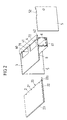
- the FIG. 1 shows a work table 1, which comprises a top plate 2 and a base plate 3.
- the base plate 3 is also referred to below as the lower plate.
- the top plate 2 and the base plate 3 are arranged parallel to each other and lie directly on each other. They are about one in the FIGS. 8 and 9 exemplary shown linear guide in its plane of extent, ie in the horizontal direction, relative to each other movable.
- the upper plate 2 via the linear guide relative to the base plate 3 is displaceable, in the illustrated embodiment such that the upper plate 2, starting from a in the Figures 5 and 6 illustrated closed position in a in the FIGS. 1 and 4 shown opened position is displaceable.
- the work table 1 is formed according to the usual shape of a desk in a rectangular shape. He thus has two narrow sides 101, 102, an end face 103 and a rear side 104. Adjacent to the end face 103, and thus adjacent to a user of the work table facing away from the long side of the work table, the base plate 3 has two recesses 71, 72. Between the recesses 71, 72, the base plate webs 31, 32, 33 forms. It should be noted that the presence of two recesses 71, 72 is to be understood merely as an example. It can also be provided a different number of recesses, optionally in another form and elsewhere in the base plate. 3
- the base plate 3 is connected to the two narrow sides 101, 102 of the work table 1 in each case with at least one stand element 5.
- a stand element is formed in each case by a rectangular plate 5.
- table legs may be provided as stand elements.
- the work table 1 further has a receiving compartment 6. This is rectangular in cross section, wherein the base plate 3 facing upper side is open.
- the receiving compartment 6 extends from a narrow side 101 to the other narrow side 102 of the work table and is secured to the base plate 3 and / or the stand elements 5, that through the recesses 71, 72 in the base plate 3 from above access to the receiving compartment. 6 given is.
- a cross-wood 4 is further provided, which is fixedly connected to the base plate 3.
- the crossbar 4 which may also be referred to as a transverse element or cross bar, has a longitudinal edge facing a user 40, which in the closed state of the work table, as in the Figures 5 and 6 is shown directly adjacent to a front longitudinal edge 20 of the top plate 2.
- the cross-wood 4 is formed as well as the top plate 2 and the base plate 3 plate-shaped and has the same thickness as the top plate 2 in one embodiment.
- the width is the same as the width of the worktable.
- the work table 1 When the longitudinal edge 20 of the top plate 2 comes against the longitudinal edge 40 of the cross-wood 4, the work table 1 is closed. About an optional locking device, not shown, which includes, for example, a lock cylinder can be locked in the closed position of the work table 1, so that the top plate 2 is no longer movable relative to the base plate 3.
- a locking device not shown, which includes, for example, a lock cylinder can be locked in the closed position of the work table 1, so that the top plate 2 is no longer movable relative to the base plate 3.
- the dovetail guide causes a form fit, which prevents vertical movement of the top plate 2 relative to the base plate 3, so that the top plate 2 can not be folded up.
- the dimensions of the bar 22 are consistent with the dimensions of the top plate 2, so that they are flush on the side edge of the worktable 1.
- the thickness of the strip 22 corresponds to the thickness of the base plate 3.
- the strip 22 thus forms at the same time a kind of screen that covers the base plate 2 optically. Optically, the impression arises as if a single worktop with a thickness is present which is equal to the sum of the thicknesses of top plate 2 and base plate 3. These are preferably both the same thickness, so that visually the top plate 2 appears twice as thick as it actually is.
- the thickness of the base plate 3 and the top plate 3 is for example, in each case between 10 and 30 mm, for example, in each case 20 mm, for which case there is optically a lateral view of the working unit a 40 mm thick worktop.
- the stand element 5 at its upper edge, which is connected to the base plate 3, an elongated recess 52.
- This recess 52 serves for the optional attachment of a connecting part, for example in the form of a connecting plate or wood element, by means of which the working unit can be connected to a further, correspondingly formed working unit.
- FIG. 10 shows a further embodiment of the invention, in which in the base plate 3, an additional longitudinal guide in the form of a groove 36 is formed.
- the groove extends in the direction of displacement of the plates 2, 3.
- a retractable monitor can be integrated into the work table.
- the monitor is arranged in the receiving compartment 6 and can be moved vertically upward by a suitable device from the receiving compartment 6, so that it can be used as a computer screen.
- a slot or the like is located in the top plate 2, through which the monitor can move out of the receptacle 6 upwards or can be sunk into the receptacle 6.
- FIGS. 11 to 16 show a further embodiment of a work table 1 ', which essentially by the additional training of a monitor compartment of the embodiment of FIGS. 1 to 10 different.
- the mechanism for opening of the work table using a top plate 2 and a bottom plate 3, which are arranged parallel to each other and movable in the horizontal direction relative to each other, is the same.
- the same reference numerals on the one hand in the embodiment of FIGS. 11 to 16 and on the other in the embodiment of FIGS. 1 to 10 denote identical or corresponding parts.
- Two stand elements 5 are as in relation to the FIG. 3 explained educated.
- the actuator 110 is formed as a rectangular profile and is guided on the rectangular housing 115. As a result, a rotatability and thus unwanted pivoting of the monitor are prevented.
- a preferred application of the work table according to the invention is as mentioned in educational institutions such as schools, call centers and open-plan offices.
- By locking the top plate 3 with the base plate 2 can be ensured that unauthorized third parties can not gain access to the arranged in the receiving compartment hardware.
- the encapsulation of the computer in the storage compartment of the worktable reduces the noise level in the room.
Abstract
Description
Die Erfindung betrifft einen Arbeitstisch mit einem Aufnahmefach, das zur Unterbringung technischer Geräte ausgebildet ist. Bei den technischen Geräten handelt es sich insbesondere um Datenverarbeitungs- und Kommunikationsgeräte, die in den Arbeitstisch integriert sind.The invention relates to a work table with a receiving compartment, which is designed to accommodate technical equipment. The technical devices are in particular data processing and communication devices that are integrated in the work table.
Moderne Arbeitsplätze weisen eine Vielzahl technischer Geräte wie Personal Computer (PCs), Drucker, Diktiergeräte, Telefone und Telefaxe auf. Dies führt häufig dazu, dass die Arbeitsplatte eines Arbeitstisches als Geräteabstellplatz umfunktioniert und für Büroarbeiten kaum noch nutzbar ist. Insbesondere Personal Computer nehmen einen erheblichen Platz in Anspruch.Modern workplaces have a variety of technical devices such as personal computers (PCs), printers, dictaphones, telephones and faxes. This often means that the worktop of a work table is converted as a device storage space and barely usable for office work. In particular, personal computers take up a considerable amount of space.
Aus der Druckschrift
In der
Der vorliegenden Erfindung liegt die Aufgabe zugrunde, einen weiteren Arbeitstisch mit einem Aufnahmefach zur Unterbringung technischer Geräte bereitzustellen, der eine Integration technischer Geräte, insbesondere eines Computers sowie der zugehörigen Verkabelung, in den Arbeitstisch ermöglicht.The present invention has for its object to provide a further work table with a receptacle for accommodating technical equipment, which allows integration of technical equipment, in particular a computer and the associated wiring in the work table.
Diese Aufgabe wird erfindungsgemäß durch einen Arbeitstisch mit den Merkmalen des Anspruchs 1 gelöst. Ausgestaltungen der Erfindung sind in den Unteransprüchen angegeben.This object is achieved by a work table with the features of
Danach weist der Arbeitstisch eine obere und eine untere Platte auf, die parallel und unmittelbar aneinander angrenzend angeordnet und dabei relativ zueinander verschiebbar sind. Durch Verschieben der Platten relativ zueinander wird das Aufnahmefach freigegeben oder geschlossen. Weiter ist ein hinteres Querelement vorgesehen, an das die obere Platte in der Verschlussposition, in der das Aufnahmefach geschlossen ist, unmittelbar angrenzt.Thereafter, the work table on an upper and a lower plate, which are arranged parallel and immediately adjacent to each other and thereby displaced relative to each other. By moving the plates relative to each other, the receptacle is released or closed. Further, a rear cross member is provided, to which the upper plate in the closed position, in which the receiving compartment is closed, immediately adjacent.
Die vorliegende Erfindung stellt eine Lösung bereit, bei der durch horizontales Verschieben zweier übereinander liegender Platten ein Aufnahmefach freigegeben oder geschlossen werden kann. Das Aufnahmefach dient dabei der Aufnahme und Unterbringung technischer Geräte wie eines Computers. In der geöffneten Position können technische Geräte und die zugehörige Verkabelung in das Aufnahmefach eingeführt werden. In der geschlossenen Position sind die technischen Geräte und zugehörige Kabel in dem Aufnahmefach sicher verstaut, ohne dass sie Platz auf der Arbeitsoberfläche des Arbeitstisches oder neben oder unter dem Arbeitstisch beanspruchen würden, und unter Bereitstellen eines aufgeräumten Erscheinungsbildes. Durch Angrenzen der oberen Platte in der Verschlussposition unmittelbar an das Querelement wird ein im Wesentlichen vollständiger und abschließbarer Verschluss des Aufnahmefaches in der Verschlussposition ermöglicht.The present invention provides a solution in which by horizontal displacement of two superimposed plates, a receiving compartment can be released or closed. The receptacle serves to accommodate and accommodate technical equipment such as a computer. In the open position, technical devices and the associated wiring can be inserted into the receptacle. In the closed position, the technical devices and associated cables are safely stowed in the receptacle without requiring space on the work surface of the worktable or next to or below the worktable, and providing a tidy appearance. By abutment of the top plate in the closed position directly to the cross member, a substantially complete and lockable closure of the receiving compartment in the closed position is made possible.
Dass die obere Platte in der Verschlussposition unmittelbar an das hintere Querelement angrenzt, bedeutet dabei, dass die obere Platte zumindest abschnittsweise direkt an das Querelement angrenzt, ohne dass dazwischen ein Spalt verbleiben würde. Dadurch wird jedoch nicht ausgeschlossen, dass lokale Öffnungen, etwa kreisförmige oder rechteckförmige Öffnungen zum Herausführen von Kabeln aus dem Aufnahmefach, zwischen dem Querelement und der oberen Platte vorgesehen sind. Weiter bedeutet die Qualifizierung des Querelements als hinteres Querelement, dass sich dieses bezogen auf die Sitzposition eines Nutzers des Arbeitstisches an oder nahe der Rückseite des Arbeitstisches befindet.The fact that the upper plate directly adjoins the rear transverse element in the closed position means that the upper plate, at least in sections, directly adjoins the transverse element without a gap remaining therebetween. However, this does not exclude that local openings, such as circular or rectangular openings for taking out cables from the receiving compartment, are provided between the cross member and the upper plate. Next, the qualification of the cross member as a rear cross member means that this is based on the sitting position of a user of the work table at or near the back of the work table.
Dass die obere und die untere Platte "unmittelbar aneinander angrenzend" angeordnet sind ist dahingehend zu verstehen, dass keine weiteren Bestandteile des Arbeitstisches dazwischen angeordnet sind, vielmehr die obere und die untere Platte in ihrer parallelen Anordnung direkt aufeinander folgen. Die Anordnung "unmittelbar aneinander angrenzend" bedeutet dagegen nicht, dass die Platten sich notwendigerweise flächig berühren. Es kann durchaus ein geringer Abstand zwischen den Platten vorgesehen sein, insbesondere von bis zu etwa 1 mm, der beispielsweise durch Führungselemente wie z.B. Längsnuten der einen Platte und darin eingreifende Längsführungen der anderen Platte verursacht ist.The fact that the upper and lower plates are arranged "immediately adjacent" is to be understood as meaning that no further components of the work table are interposed therebetween, but rather that the upper and lower plates directly follow one another in their parallel arrangement. On the other hand, the arrangement "immediately adjacent to one another" does not mean that the plates necessarily touch flatly. It may well be provided a small distance between the plates, in particular of up to about 1 mm, for example, by guide elements such. Longitudinal grooves of a plate and engaging therein longitudinal guides of the other plate is caused.
In einem Ausführungsbeispiel der Erfindung stellt die obere Platte die Arbeitsplatte des Arbeitstisches dar. In der unteren Platte ist mindestens eine Aussparung vorgesehen, über die ein Zugang zu dem unterhalb der unteren Platte angeordneten Aufnahmefach bereitgestellt wird. Durch Vorschieben der oberen Platte gegenüber der unteren Platte wird die Aussparung in der unteren Platte zugänglich oder verschlossen und damit ein Zugang zu dem Aufnahmefach freigegeben oder verschlossen.In one embodiment of the invention, the top plate is the worktop of the worktable. At least one recess is provided in the bottom plate to provide access to the receptacle located below the bottom plate. By advancing the upper plate relative to the lower plate, the recess in the lower plate is accessible or closed and thus released or closed access to the receiving compartment.
Das Aufnahmefach wird beispielsweise durch einen Kanal gebildet ist, der sich von einer Schmalseite des Arbeitstisches zu der anderen Schmalseite des Arbeitstisches erstreckt.
Das Aufnahmefach ist an seiner der unteren Platte zugewandten Seite offen ausgebildet und derart am Arbeitstisch befestigt, dass durch die Aussparung ein Zugang zu dem Aufnahmefach vorliegt. Der Querschnitt ist beispielsweise rechteckförmig.The receiving compartment is formed for example by a channel which extends from a narrow side of the work table to the other narrow side of the work table.
The receptacle is open on its side facing the lower plate and secured to the work table such that there is access to the receptacle through the recess. The cross section is for example rectangular.
Die Höhe des Aufnahmefachs ist beispielsweise derart bemessen, dass ein kleiner Computer wie beispielsweise ein Slimline-PC oder ein Mini-PC in dem Aufnahmefach verstaut werden kann. Die Höhe des Aufnahmsfachs ist jedoch variabel und es können auch größere PCs darin untergebracht werden. Es kann mit einem elektromagnetische Strahlung abschirmenden Material und/oder einem schallabsorbierenden Material ausgekleidet sein. Das Aufnahmefach kann des Weiteren mehrere Öffnungen aufweisen, die z.B. das Durchführen von Leitungen zur Stromversorgung, zur Verbindung mit Peripheriegeräten und zur Telekommunikation ermöglichen.The height of the receiving compartment is for example such that a small computer such as a slimline PC or a mini-PC in the receptacle can be stowed. However, the height of the recording compartment is variable and larger PCs can be accommodated therein. It may be lined with an electromagnetic radiation shielding material and / or a sound absorbing material. The receptacle may further comprise a plurality of openings, for example, allow the implementation of lines for power supply, for connection to peripheral devices and telecommunications.
Wie bereits erläutert, ist ein hinteres Querelement vorgesehen, das auch als Querholz oder Querleiste bezeichnet werden und aus einem beliebigen Material bestehen kann. Es kann vorgesehen sein, dass das Querelement an der einem Nutzer des Arbeitstisches abgewandten Stirnseite des Arbeitstisches angeordnet ist, sich zwischen den Schmalseiten des Arbeitstisches erstreckt und eine einem Nutzer des Arbeitstisches zugewandte Längskante aufweist, an die die einem Nutzer des Arbeitstisches abgewandten Längsseite der obere Platte in der Verschlussposition unmittelbar angrenzt. Das Querelement ist dabei beispielsweise plattenförmig ausgebildet, auf der unteren Platte angeordnet und fest mit dieser verbunden, und besitzt die gleiche Dicke wie die obere Platte. Ebenso kann vorgesehen sein, dass die untere Platte vor dem Querelement endet. Für diesen Fall weist das Querelement bevorzugt eine Dicke auf, die der Summe der Dicken von Unterplatte und Oberplatte entspricht.As already explained, a rear cross member is provided, which are also referred to as a cross-wood or cross bar and can be made of any material. It can be provided that the transverse element is arranged on the end face of the work table facing away from a user of the work table, extends between the narrow sides of the work table and has a longitudinal edge facing a user of the work table, to which the longitudinal side of the upper plate facing away from a user of the work table immediately adjacent in the closed position. The cross member is, for example, plate-shaped, arranged on the lower plate and fixedly connected thereto, and has the same thickness as the upper plate. It can also be provided that the lower plate ends in front of the transverse element. For this case, the cross member preferably has a thickness which corresponds to the sum of the thicknesses of the lower plate and the upper plate.
Über das Querelement wird ein stirnseitiger Anschlag für die obere Platte bereitgestellt.About the cross member a frontal stop for the top plate is provided.
In einer weiteren Ausgestaltung weist der Arbeitstisch eine Verriegelungsvorrichtung auf, mittels derer eine Relativbewegung zwischen der oberen Platte und der unteren Platte in der Verschlussposition sperrbar ist. Hierdurch können in dem Aufnahmefach enthaltene Computerhardware oder andere technische Geräte vor dem Zugriff Unbefugter geschützt werden.In a further embodiment, the work table has a locking device, by means of which a relative movement between the upper plate and the lower plate in the closed position can be blocked. As a result, computer hardware or other technical devices contained in the receptacle can be protected from access by unauthorized persons.
Weiter weist der Arbeitstisch bevorzugt Mittel beispielsweise in Form eines Anschlages oder einer Rastvorrichtung auf, die eine Relativbewegung der oberen Platte relativ zu der unteren Platte nur über eine definierte Wegstrecke erlauben. Hierdurch wird verhindert, dass die obere Platte vollständig von der unteren Platte entfernt werden kann.Furthermore, the worktable preferably has means, for example in the form of a stop or a detent device, which allow a relative movement of the upper plate relative to the lower plate only over a defined path. This prevents the top plate from being completely removed from the bottom plate.
Zur Bereitstellung einer definierten Relativbewegung zwischen der oberen Platte und der unteren Platte ist in einer Ausgestaltung der Erfindung eine Linearführung vorgesehen, die ausschließlich eine Bewegung der oberen Platte gegenüber der unteren Platte in der Ebene der jeweiligen Platten erlaubt. Die Linearführung ist in einer Ausführungsvariante als Schwalbenschwanzführung ausgeführt. In einer anderen Ausführungsvariante umfasst die Linearführung eine mit der oberen Platte verbundene Leiste, die den Rand der unteren Platte umgreift und dabei einen Formschluss zwischen der oberen Platte und der unteren Platte bereitstellt.In order to provide a defined relative movement between the upper plate and the lower plate, in one embodiment of the invention, a linear guide is provided which exclusively controls a movement of the upper plate relative to the bottom plate in the plane of the respective plates allowed. The linear guide is designed in a variant as a dovetail guide. In another embodiment variant, the linear guide comprises a bar connected to the upper plate, which surrounds the edge of the lower plate and thereby provides a positive connection between the upper plate and the lower plate.
Zusätzlich kann mindestens eine Längsnut in der einen Platte ausgebildet sein, in die mindestens ein entsprechend geformter Vorsprung der anderen Platte eingreift. Bevorzugt sind mindestens drei parallele Längsnuten in der einen Platte vorgesehen, etwa einer Höhe von 5mm bis 10mm, wobei in der anderen Platte jeweils eine längliche Führung, beispielsweise eine Kunststoffführung, vorgesehen ist, die in die Längsnut eingreift. Dies reduziert bzw. eliminiert die Gefahr eines Verkantens der beiden Platten bei einer Verschiebebewegung. Über die Längsnuten und die länglichen Führungen kann in einer Ausführungsvariante ein minimaler Abstand zwischen den beiden Platten von bis zu 1 mm, insbesondere von 0,5 mm hergestellt werden.In addition, at least one longitudinal groove may be formed in one plate, into which engages at least one correspondingly shaped projection of the other plate. Preferably, at least three parallel longitudinal grooves are provided in the one plate, for example, a height of 5mm to 10mm, wherein in the other plate in each case an elongated guide, for example a plastic guide, is provided, which engages in the longitudinal groove. This reduces or eliminates the risk of tilting of the two plates during a displacement movement. About the longitudinal grooves and the elongate guides can be made in a variant, a minimum distance between the two plates of up to 1 mm, in particular of 0.5 mm.
In einem weiten Ausführungsbeispiel der vorliegenden Erfindung ist zusätzlich zu dem Aufnahmefach mindestens ein Monitorfach vorgesehen, das der Aufnahme mindestens eines versenkbaren Monitores dient. Das Monitorfach befindet sich dabei aus Sicht des Nutzers des Arbeitstisches hinter dem Aufnahmefach und grenzt an die hintere Stirnseite des Arbeitstisches.In a wide embodiment of the present invention, at least one monitor compartment is provided in addition to the receptacle, which serves to accommodate at least one retractable monitor. The monitor compartment is located behind the receiving compartment from the perspective of the user of the work table and is adjacent to the rear end side of the work table.
Dabei ist in einer Ausgestaltung vorgesehen, dass das Monitorfach derart im Arbeitstisch ausgebildet ist, dass auch bei geöffnetem Aufnahmefach kein Zugang von oben zum Monitorfach gegeben ist. Das Monitorfach und das Aufnahmefach sind somit bevorzugt vollständig getrennt, so dass über das Monitorfach kein Zugang zu dem Aufnahmefach und insbesondere im Aufnahmefach angeordneten Rechnern oder anderen elektrischen und elektronischen Bauteilen gegeben ist.In this case, it is provided in one embodiment that the monitor compartment is designed in such a way in the work table, that even with the receiving compartment open no access from above to the monitor compartment is given. The monitor compartment and the receiving compartment are thus preferably completely separate, so that there is no access to the receiving compartment and, in particular, computers or other electrical and electronic components arranged in the receiving compartment via the monitor compartment.
Hierzu ist es in einer Ausgestaltung vorgesehen, dass das Monitorfach unterhalb des hinteren Querelementes ausgebildet ist. Dabei ist im Querelement mindestens eine Klappe ausgebildet, die sich bei einem vertikalen Ausfahren des Monitors aus dem Monitorfach öffnet und die sich beim Einfahren des Monitores in das Monitorfach wieder schließt. Die Klappe ist dabei selbstöffnend und selbstschließend ausgebildet, d. h. ein Öffnen und Schließen erfolgt allein aufgrund der Verfahrbewegung des Monitors.For this purpose, it is provided in one embodiment that the monitor compartment is formed below the rear cross member. In this case, at least one flap is formed in the transverse element, which opens at a vertical extension of the monitor from the monitor compartment and which closes when retracting the monitor in the monitor compartment again. The flap is self-opening and self-closing, ie an opening and closing takes place solely due to the movement of the monitor.
Des Weiteren kann vorgesehen sein, dass das Monitorfach eine größere Höhe und/oder eine geringere Tiefe aufweist als das Aufnahmefach. Auch kann vorgesehen sein, dass es unten offen ausgebildet ist. Dies weist den Vorteil auf, dass Dinge wie z. B. Schreibstifte, die in das Monitorfach fallen, in einfacher Weise vom Boden wieder aufgehoben werden können.Furthermore, it can be provided that the monitor compartment has a greater height and / or a smaller depth than the receiving compartment. It can also be provided that it is designed to be open at the bottom. This has the advantage that things such. As pens that fall into the monitor compartment, can be repealed in a simple manner from the ground again.
Die Erfindung wird nachfolgend unter Bezugnahme auf die Figuren der Zeichnungen anhand mehrerer Ausführungsbeispiele näher erläutert. Es zeigen:
- Fig.1
- in perspektivischer Darstellung einen erfindungsgemäßen Arbeitstisch mit einer Oberplatte und einer Grundplatte im geöffneten Zustand;
- Fig. 2
- eine perspektivische Ansicht des Arbeitstisches der
Fig. 1 in teilweise zusammengebautem Zustand, wobei die Oberplatte getrennt von der Grundplatte dargestellt ist; - Fig.3
- den Arbeitstisch der
Fig. 1 in teilweise zusammengebautem Zustand; - Fig. 4
- eine weitere perspektivische Ansicht des Arbeitstisches der
Fig. 1 in geöffnetem Zustand; - Fig.5
- eine perspektivische Ansicht in Richtung der Stirnseite des Arbeitstisches der
Fig. 1 in geschlossenem Zustand; - Fig. 6
- eine perspektivische Ansicht in Richtung der Rückseite des Arbeitstisches der
Fig. 1 in geschlossenem Zustand; - Fig. 7
- eine beispielhafte Ausgestaltung des Aufnahmefachs des Arbeitstisches;
- Fig.8
- eine perspektivische Darstellung einer seitlichen Linearführung zwischen der Oberplatte und der Grundplatte, wobei der Linearführung eine Schwalbenschwanzverzahnung aufweist;
- Fig. 9
- in Querschnittsansicht ein alternatives Ausführungsbeispiel einer Linearführung zwischen der Oberplatte und der Grundplatte, wobei die Oberplatte mit einem die Grundplatte seitlich umgreifenden Formschlussteil verbunden ist;
- Fig. 10
- eine in der Grundplatte ausgebildete längliche Führungsnut, die eine verkantfreie Führung zwischen der Oberplatte und der Grundplatte bereitstellt:
- Fig. 11
- in perspektivischer Darstellung ein weiteres Ausführungsbeispiel eines Arbeitstisches in teilweise zusammengebautem Zustand;
- Fig. 12
- eine Seitenansicht des Arbeitstisches der
Figur 11 , ohne dass das dem Betrachter zugewandte Standelement des Arbeitstisches dargestellt ist; - Fig. 13
- eine perspektivische Darstellung von Teilelementen des Arbeitstisches der
Figuren 11 und12 , wobei die seitlichen Standelemente, ein hinteres Querelement, eine rückseitige Platte und eine an dieser angeordnete Hydraulik dargestellt sind; - Fig. 14
- den Arbeitstisch der
Figuren 11 bis 13 , wobei der Arbeitstisch in geöffnetem Zustand entsprechend derFigur 1 und mit ausgefahrener Hydraulik dargestellt ist; - Fig. 15
- den Arbeitstisch der
Figuren 11 bis 14 , wobei der Arbeitstisch in geschlossenem Zustand und mit ausgefahrener Hydraulik dargestellt ist; und - Fig. 16
- den Arbeitstisch der
Figuren 11 bis 15 , wobei der Arbeitstisch in geschlossenem Zustand und mit eingefahrener Hydraulik dargestellt ist.
- Fig.1
- in perspective view of a work table according to the invention with a top plate and a base plate in the open state;
- Fig. 2
- a perspective view of the work table of
Fig. 1 in a partially assembled condition, the top panel being shown separated from the base panel; - Figure 3
- the work desk of
Fig. 1 in partially assembled condition; - Fig. 4
- another perspective view of the work table of the
Fig. 1 in open condition; - Figure 5
- a perspective view in the direction of the front side of the work table of
Fig. 1 in closed condition; - Fig. 6
- a perspective view towards the back of the work table of
Fig. 1 in closed condition; - Fig. 7
- an exemplary embodiment of the receiving compartment of the work table;
- Figure 8
- a perspective view of a lateral linear guide between the top plate and the base plate, wherein the linear guide has a dovetail toothing;
- Fig. 9
- in cross-sectional view an alternative embodiment of a linear guide between the top plate and the base plate, wherein the top plate is connected to a laterally surrounding the base plate form-fitting part;
- Fig. 10
- an elongated guide groove formed in the base plate providing a non-tilted guide between the top plate and the base plate:
- Fig. 11
- a perspective view of another embodiment of a work table in partially assembled state;
- Fig. 12
- a side view of the work table of the
FIG. 11 , without that the stand facing the viewer of the work table is shown; - Fig. 13
- a perspective view of sub-elements of the work table of
Figures 11 and12 , wherein the side stand elements, a rear cross member, a rear plate and a hydraulic arranged thereon are shown; - Fig. 14
- the work desk of
FIGS. 11 to 13 , wherein the work table in the open state according toFIG. 1 and shown with the hydraulics extended; - Fig. 15
- the work desk of
FIGS. 11 to 14 wherein the work table is shown in the closed state and with extended hydraulics; and - Fig. 16
- the work desk of
FIGS. 11 to 15 , wherein the work table is shown in the closed state and with retracted hydraulics.
Die
Die Oberplatte 2 stellt die Arbeitsplatte des Arbeitstisches 1 dar. Sie ist beispielsweise als laminatbeschichtete Möbelplatte ausgeführt. Die Grundplatte 3 besteht bevorzugt ebenfalls aus einem Holzwerkstoff, wie beispielsweise einer Sperrholzplatte, einer Laminatplatte oder einer Spanplatte. Sämtliche Bestandteile des Arbeitstisches 1 sind in einer Ausgestaltung aus Holz gefertigt.The
Der Arbeitstisch 1 ist entsprechend der üblichen Form eines Schreibtisches im rechteckförmig ausgebildet. Er besitzt somit zwei Schmalseiten 101, 102, eine Stirnseite 103 und eine Rückseite 104. Benachbart der Stirnseite 103, und damit benachbart der einem Nutzer des Arbeitstisches abgewandten Längsseite des Arbeitstisches, weist die Grundplatte 3 zwei Aussparungen 71, 72 auf. Zwischen den Aussparungen 71, 72 bildet die Grundplatte Stege 31, 32, 33 aus. Dabei wird darauf hingewiesen, dass das Vorhandensein von zwei Aussparungen 71, 72 lediglich beispielhaft zu verstehen ist. Es können auch eine andere Anzahl von Aussparungen vorgesehen sein, wahlweise auch in anderer Form und an anderer Stelle der Grundplatte 3.The work table 1 is formed according to the usual shape of a desk in a rectangular shape. He thus has two
Die Grundplatte 3 ist an den beiden Schmalseiten 101, 102 des Arbeitstisches 1 jeweils mit mindestens einem Standelement 5 verbunden. Im dargestellten Ausführungsbeispiel wird ein Standelement jeweils durch eine rechteckförmige Platte 5 gebildet. Alternativ können jedoch auch Tischbeine als Standelemente vorgesehen sein.The
Der Arbeitstisch 1 weist des Weiteren ein Aufnahmefach 6 auf. Dieses ist im Querschnitt rechteckförmig ausgebildet, wobei die der Grundplatte 3 zugewandte obere Seite offen ausgebildet ist. Das Aufnahmefach 6 erstreckt sich von einer Schmalseite 101 bis zur anderen Schmalseite 102 des Arbeitstisches und ist so an der Grundplatte 3 und/oder den Standelementen 5 befestigt, dass durch die Aussparungen 71, 72 in der Grundplatte 3 von oben ein Zugang zu dem Aufnahmefach 6 gegeben ist.The work table 1 further has a
An der dem Nutzer abgewandten Stirnseite 103 des Arbeitstisches 1 ist des Weiteren ein Querholz 4 vorgesehen, das mit der Grundplatte 3 fest verbunden ist. Das Querholz 4, das auch als Querelement oder Querleiste bezeichnet werden kann, weist eine einem Nutzer zugewandte Längskante 40 auf, die im geschlossenen Zustand des Arbeitstisches, wie er in den
Das Querholz 4 stellt über seine Längskante 40 einen Anschlag für die Bewegung der Oberplatte 2 dar. Zusätzlich oder alternativ kann eine Begrenzung der Bewegung der Oberplatte 2 durch Längsnuten (vgl.
Wenn die Längskante 20 der Oberplatte 2 gegen die Längskante 40 des Querholzes 4 gelangt, ist der Arbeitstisch 1 geschlossen. Über eine optionale nicht dargestellte Verriegelungsvorrichtung, die beispielsweise einen Schließzylinder umfasst, kann in der geschlossenen Position der Arbeitstisch 1 verriegelt werden, so dass die Oberplatte 2 nicht mehr relativ zu der Grundplatte 3 bewegbar ist.When the
In den dargestellten Figuren ist das Querholz 4 als auf der Grundplatte 3 angeordnete und fest verbundene Querleiste ausgebildet. Alternativ kann ebenso vorgesehen sein, dass die Grundplatte vor dem Querholz endet und dieses dabei mit der Grundplatte und/oder der Seitenelementen verbunden ist. Für diesen Fall ist das Querholz dicker ausgebildet und weist eine Dicke auf, die zumindest gleich der Summe der Dicken von Oberplatte 2 und Grundplatte 3 ist. Das Querholz 4 kann grundsätzlich in beliebiger Weise ausgebildet sein, so lange es einen hinteren Anschlag für die Oberplatte 2 bereitstellt.In the illustrated figures, the
Das Aufnahmefach 6 dient der Aufnahme technischer Geräte, insbesondere eines Computers sowie einer zugehörigen Verkabelung und Stromversorgung. Dies ist beispielhaft in der
Über die Steckdose 610 können weitere technische Geräte im Aufnahmefach 6 angeordnet werden.About the
Die Abmessungen des Aufnahmefachs 6 betragen beispielsweise 0,3 m x 0,3 m x 1,5 m (Höhe x Breite x Länge). Je nach benötigtem Platzbedarf können die Abmessungen aber auch anders sein. Beispielsweise kann die Höhe zwischen 0,1 m und 0,5 m, die Breite zwischen 0,1 m und 0,5 m und die Länge zwischen 0,8 m und 2,5 m variieren.The dimensions of the
Das Aufnahmefach 6 sowie die Standelemente 5 des Arbeitstisches 1 weisen eine Mehrzahl von Öffnungen auf, die die Durchführung elektrischer Kabel ermöglichen, und dadurch beispielsweise das Herausführen von Kabeln aus dem Aufnahmefach 6 zum Anschluss eines Bildschirmes, zum Anschluss an eine in einer benachbarten Wand ausgebildeten Steckdose oder zum kommunikationstechnischen Anschluss an benachbarte, entsprechend ausgebildete Arbeitstische. Hierzu weisen die Standelemente 5 Aussparungen 51 auf, die im Bereich der Stirnseiten des Aufnahmefachs 6 in den Standelementen 5 ausgebildet sind, so dass Kabel in Längsrichtung des Aufnahmefaches 6 aus der Arbeitseinheit 1 herausgeführt bzw. in diese hineingebracht werden können. Des Weiteren weist das Aufnahmefach 6, wie in der
Weitere Aussparungen 9 (vgl.
Die Anzahl, Größe und Form der Öffnungen 9 ist lediglich beispielhaft dargestellt. Beispielsweise kann alternativ vorgesehen sein, dass im Wesentlichen rechteckförmige Aussparungen entweder an der Längskante 20 der Oberplatte 2, an der Längskante 40 des Querholzes 4 oder durch diese beiden zusammen gebildet sind, die dann durch eine oder mehrere Bürstenleisten verschlossen sind, durch die Kabel in das Aufnahmefach 6 geführt bzw. aus diesem herausgeführt werden können.The number, size and shape of the
Anhand der
Durch die beschriebene Linearführung wird zum einen ein Verschieben der Oberplatte 2 relativ zu der Grundplatte 3 ermöglicht. Gleichzeitig bewirkt die Schwalbenschwanzführung einen Formschluss, der eine vertikale Bewegung der Oberplatte 2 gegenüber der Grundplatte 3 verhindert, so dass die Oberplatte 2 nicht hochgekantet werden kann.By the linear guide described on the one hand, a displacement of the
Die Herstellung der Schwalbenschwanzführung ist in einfacher Weise möglich, da hierzu lediglich die Unterplatte 3 entlang einer Linie, die später die angeschrägte Stirnseite 35 bildet, schräg durchgesägt werden muss. Das dabei entstehende abfallende Teil bildet die Leiste 22 und wird an der Unterseite der Oberplatte 2 befestigt.The preparation of the dovetail guide is possible in a simple manner, since this only the
Die Abmessungen der Leiste 22 stimmen mit den Abmessungen der Oberplatte 2 überein, so dass diese an der Seitenkante des Arbeitstisches 1 bündig abschließen. Die Dicke der Leiste 22 entspricht der Dicke der Grundplatte 3. Die Leiste 22 bildet damit gleichzeitig eine Art Sichtblende, die die Grundplatte 2 optisch verdeckt. Optisch entsteht dabei der Eindruck, als ob eine einzige Arbeitsplatte mit einer Dicke vorhanden sei, die gleich der Summe der Dicken von Oberplatte 2 und Grundplatte 3 ist. Diese sind bevorzugt beide gleich dick, so dass optisch die Oberplatte 2 doppelt so dick erscheint als sie tatsächlich ist. Die Dicke der Grundplatte 3 und der Oberplatte 3 beträgt beispielsweise jeweils zwischen 10 und 30 mm, beispielsweise jeweils 20 mm, für welchen Fall optisch bei seitlicher Betrachtung der Arbeitseinheit eine 40 mm starke Arbeitsplatte vorliegt.The dimensions of the
Zum Erzielen der optischen Wirkung einer einzigen Arbeitsplatte weist die Oberplatte 2 auch an ihrer Rückseite 104 eine Sichtblende 23 auf, wie beispielsweise in den
In der
Zur Verbindung der Oberplatte 2 mit der Grundplatte 3 wird die Oberplatte mittels der Linearführung auf die Grundplatte 3 aufgeschoben. In der
Zur Verbindung der einzelnen Elemente, insbesondere zur Verbindung der Grundplatte 3 mit den Standelementen 4 sowie zur Verbindung des Aufnahmefachs 6 zum einen mit der Grundplatte 3 und zum anderen mit den Standelementen 5 sind beispielsweise Schrauben 8 vorgesehen, die in üblicher Weise die entsprechenden Teile verbinden.For connecting the individual elements, in particular for connecting the
Wie insbesondere in den
Die
In beiden Varianten der Längsführung weist die Unterplatte 3 eine geringfügig geringere Länge zwischen den beiden Schmalseiten 101, 102 auf, da nicht die Unterplatte 3 selbst, sondern die Leiste 22, 24 bündig mit der Oberplatte 2 abschließt. Abgesehen des Weiteren von dem Querholz 4 weisen die obere Platte 2 und die untere Platte 3 jedoch im wesentlichen gleiche Abmessungen auf.In both variants of the longitudinal guide, the
Die in den
Die
Es kann vorgesehen sein, dass, nachdem die Oberplatte 2 auf der Grundplatte 3 angeordnet ist, die Oberplatte 2 nur über eine begrenzte Wegstrecke relativ zu der Grundplatte 3 bewegbar ist. So soll zum einen gewährleistet werden, dass die Öffnungen 71, 72 zum Zugang zum Aufnahmefach 6 durch Verschieben der Oberplatte 2 freigelegt werden können. Andererseits soll eine vollständige Entfernung der Oberplatte 2 von der Grundplatte 3 verhindert werden. Diese Möglichkeit könnte beispielsweise bei der Verwendung des Arbeitstisches in Schulen Anlass für eine unsachgemäße Nutzung des Arbeitstisches sein. Um die Relativbewegung zwischen den Platten 2, 3 zu begrenzen, ist beispielsweise eine Arretiervorrichtung vorgesehen, beispielsweise in Form eines (nicht dargestellten) Anschlages oder mittels einer Rastvorrichtung, die einrastet, wenn die Oberplatte 2 eine definierte Strecke gegenüber der Grundplatte 3 verschoben ist.It can be provided that, after the
In weiteren Ausgestaltungen (nicht dargestellt) kann vorgesehen sein, dass sich unterhalb der Grundplatte 3 an der einem Nutzer zugewandten Rückseite des Arbeitstisches eine oder mehrere Stiftschubladen oder Tastaturauszüge befinden. Weiter kann in die Tischplatte ein USB-Anschluss integriert sein, der den Anschluss von Geräten oder Speichermedien ermöglicht. Die entsprechende Verkabelung wird über eine der Öffnungen des Aufnahmefachs 6 in dieses geführt. Weiter können auch ein DVD- und/oder Disketten-Laufwerk als externes Laufwerk an der Grundplatte 3 und/oder in einer Schublade integriert sein.In further embodiments (not shown), it may be provided that one or more pen drawers or keyboard separations are located below the
Ebenfalls kann in einer Ausführungsvariante ein versenkbarer Monitor in den Arbeitstisch integriert sein. Der Monitor ist im Aufnahmefach 6 angeordnet und kann durch eine geeignete Vorrichtung aus dem Aufnahmefach 6 vertikal nach oben verfahren werden, so dass er als Computerbildschirm einsetzbar ist. Dazu kann vorgesehen sein, dass sich in der Oberplatte 2 ein Schlitz oder dergleichen befindet, durch den der Monitor aus dem Aufnahmefach 6 nach oben heraus verfahren bzw. in das Aufnahmefach 6 versenkt werden kann.Also, in one embodiment, a retractable monitor can be integrated into the work table. The monitor is arranged in the
In einer bevorzugten Ausgestaltung bestehen sämtliche Teile des erfindungsgemäßen Arbeitstisches 1 aus einem Holzwerkstoff, worunter insbesondere Sperrholzplatten, Laminatplatten und Spanplatten verstanden werden. Lediglich die Schrauben oder dergleichen zur Verbindung der einzelnen Elemente des Arbeitstisches bestehen aus Metall. Sofern auch das Aufnahmefach 6 aus Holz gebildet ist, kann vorgesehen sein, dieses mit einer Matte zum Schallschutz und/oder zum Schutz vor elektromagnetischer Strahlung auszukleiden.In a preferred embodiment, all parts of the work table 1 according to the invention consist of a wood material, which in particular plywood boards, laminate boards and chipboard are understood. Only the screws or the like for connecting the individual elements of the work table are made of metal. If the
Der Arbeitstisch 1 sieht eine Relativbewegung zwischen der Oberplatte 2 und der Grundplatte 3 ohne die Verwendung von Rollen, Rollauszügen, metallischen Gleitern oder ähnlichem vor. Vielmehr liegen die Oberplatte 2 und die Grundplatte 3 unmittelbar aneinander an. Dies schließt wie erläutert einen minimalen Abstand der Platten 2, 3 von bis zu 1 mm nicht aus. Über den Reibungskoeffizienten der aneinander grenzenden Flächen der Oberplatte 2 und der Grundplatte 3 kann in Ausführungsvarianten, in denen die Platten 2, 3 sich flächig berühren, die Gleitfähigkeit der Platten 2, 3 zueinander eingestellt werden.The work table 1 provides a relative movement between the
Die
Die
Zwei Standelemente 5 sind wie in Bezug auf die
Hinter dem Aufnahmefach 6, d.h. angrenzend an die einem Nutzer des Arbeitstisches 1' abgewandte Rückseite des Arbeitstisches 1', ist ein Monitorfach 9 ausgebildet. Wie insbesondere der Seitendarstellung der
Die
Die beiden Platten 91, 92, die das Monitorfach 9 bilden, erstrecken sich ebenfalls von einer Schmalseite bis zur anderen Schmalseite des Arbeitstisches 1'.The two
Das Monitorfach 9 dient der Aufnahme von zwei Monitoren (nicht dargestellt) sowie einer Hydraulik 110, 115 zum Verfahren der Monitore aus einer versenkten Position, in der sich die Monitore vollständig innerhalb des Monitorfachs 9 befinden, in eine ausgefahrene Position, in der die Monitore sich oberhalb der Schreibtischplatte 2 befinden. Die zugehörige Hydraulik ist insbesondere in der
Das Stellelement 110 ist als rechteckförmiges Profil ausgebildet und wird am rechteckförmigen Gehäuse 115 geführt. Hierdurch werden eine Verdrehbarkeit und damit ein unerwünschtes Verschwenken des Monitors verhindert.The
Das Gehäuse 115 ist über Befestigungsmittel 117 an der Innenseite der hinteren Platte 92 befestigt. Aufgrund dieses Umstandes und zusätzlich zum Verdecken der Hydraulik 110, 115 bei Betrachten des Arbeitstisches von der Rückseite ist die hintere Platte 92 fast bis zum Fußboden heruntergezogen.The
In der hinteren Querleiste 4 sind zwei Aussparungen 140 ausgebildet, die jeweils durch eine Klappe 130 abgedeckt sind. Die Klappe 130 ist dabei jeweils selbstöffnend und selbstschließend ausgebildet, d. h. sie öffnet sich automatisch, wenn der entsprechende Monitor aus dem Monitorfach 9 nach oben verfahren wird, und schließt automatisch wieder, wenn der Monitor zurück in das Monitorfach 9 verfahren wird. Die Klappe 130 besteht beispielsweise aus Blech oder Aluminium.In the
Sofern sich die Unterplatte bis zum hinteren Ende des Arbeitstisches und unterhalb des Querholzes 4 erstreckt, was in einem Ausführungsbeispiel der Fall ist, erstreckt sich die Aussparung 140 natürlich jeweils auch durch die Unterplatte.If the lower plate extends to the rear end of the work table and below the
Weiter bildet die Querleiste 4 an den Schmalseiten des Arbeitstisches 1' jeweils eine Sichtleiste 44 aus.Next forms the
Die
Wie bereits in Bezug auf die
Die
Die
Der Arbeitstisch ist beispielsweise für zwei Schülerarbeitsplätze konzipiert und weist eine Abmessung von 1,60 m x 0,80 m x 0,74 m (Breite x Tiefe x Höhe) auf.For example, the worktable is designed for two student workplaces and has a dimension of 1.60 mx 0.80 mx 0.74 m (width x depth x height).
Der beschriebene Arbeitstisch kann ebenso mit nur einem Monitor und entsprechender Hydraulik oder mit mehr als 2 Monitoren und entsprechender Hydraulik ausgebildet sein.The work table described can also be designed with only one monitor and corresponding hydraulics or with more than 2 monitors and appropriate hydraulics.
Das Ausführungsbeispiel der
Es sind somit ein oder mehrere Computer in den Arbeitstisch 1" integrierbar, dabei verschlossen und vor unbefugtem Zugriff, Verschmutzung und Beschädigung geschützt. Für einen Datentransfer kann ein USB-Anschluss beispielsweise am Monitor vorgesehen sein. Das Ein- und Ausschalten der Computer erfolgt beispielsweise über die Tastatur, so dass auch insofern kein Zugang zur Hardware erforderlich ist. Im Übrigen werden Elektronikstrahlung sowie Geräusch- und Wärmebelästigung durch Anordnung des Computers im Aufnahmefach minimiert. Der Arbeitstisch kann des Weiteren z.B. Stiftschubladen, Tastaturauszüge und dergleichen sowie Datenträger-Laufwerke aufweisen.Thus, one or more computers can be integrated into the
Eine bevorzugte Anwendung des erfindungsgemäßen Arbeitstisches erfolgt wie erwähnt in Bildungseinrichtungen wie Schulen, Callcentern und Großraumbüros. Durch eine Verriegelung der Oberplatte 3 mit der Grundplatte 2 kann sichergestellt werden, dass unbefugte Dritte keinen Zugang zu der im Aufnahmefach angeordneten Hardware erlangen können. Gleichzeitig reduziert die Kapselung des Computers im Aufnahmefach des Arbeitstisches die Geräuschbelastung im Raum.A preferred application of the work table according to the invention is as mentioned in educational institutions such as schools, call centers and open-plan offices. By locking the
Der erfindungsgemäße Arbeitstisch ist jedoch auch als Einzelplatzvariante für Büros und private Arbeitszimmer geeignet, da durch die Anordnung der technischen Geräte, insbesondere des PCs sowie der zugehörigen Verkabelung und Stromzuführung im Aufnahmefach ein "Kabelsalat" vermieden und ein aufgeräumter Eindruck bereitgestellt wird. In dem Aufnahmefach können dabei auch weitere Kabel, wie z. B. für Telefon oder Schreibtischlampe geführt werden.However, the work table according to the invention is also suitable as a single space variant for offices and private study, as avoided by the arrangement of the technical devices, in particular the PC and the associated wiring and power supply in the receptacle "cable salad" and a tidy impression is provided. In the receptacle while other cables, such. B. for telephone or desk lamp.
Trotz der effizienten Verstauung des Computers und/oder anderer technischer Geräte im Aufnahmefach 6 des Arbeitstisches ist ein einfacher und handlicher Zugang zu den technischen Geräten ermöglicht, da hierzu lediglich die Oberplatte 2 gegenüber der Grundplatte 3 verschoben werden muss. Auf der Oberplatte 2 vorhandene Gegenstände müssen dabei nicht zuvor entfernt werden, da durch die Parallelbewegung der Oberplatte 2 diese, anders als bei einer Schwenkbewegung der Oberplatte, nicht umfallen können.Despite the efficient stowage of the computer and / or other technical equipment in the
Es wird darauf hingewiesen, dass das An- und Ausschalten eines in dem Aufnahmefach 6 angeordneten Computers auch bei verschlossenem Arbeitstisch unproblematisch ist. So kann ein Ein- und Ausschalten des Computers über Power-Management-Applikationen erfolgen, wie sie an sich bekannt sind (z. B. automatisches Booten bei Stromzufluss).It should be noted that the switching on and off of a arranged in the
Die Erfindung beschränkt sich in ihrer Ausgestaltung nicht auf die vorstehend dargestellten Ausführungsbeispiele. Beispielsweise kann der Arbeitstisch statt rechteckiger Platten 2, 3 auch in anderer Weise ausgeführte Arbeitstische aufweisen, bei denen die Platten beispielsweise an ihren Ecken abgerundet oder insgesamt oval sind. Weiter kann beispielsweise vorgesehen sein, dass statt eines sich zwischen den Schmalseiten des Arbeitstisches erstreckenden Aufnahmefachs mehrere, gesondert ausgebildete Aufnahmefächer vorgesehen sind, die jeweils einer Aufnahmeöffnung in der Grundplatte zugeordnet sind.The invention is not limited in its embodiment to the embodiments shown above. For example, instead of
Claims (16)
Applications Claiming Priority (1)
| Application Number | Priority Date | Filing Date | Title |
|---|---|---|---|
| DE200910010228 DE102009010228A1 (en) | 2009-02-24 | 2009-02-24 | worktable |
Publications (2)
| Publication Number | Publication Date |
|---|---|
| EP2220963A2 true EP2220963A2 (en) | 2010-08-25 |
| EP2220963A3 EP2220963A3 (en) | 2011-12-28 |
Family
ID=42237244
Family Applications (1)
| Application Number | Title | Priority Date | Filing Date |
|---|---|---|---|
| EP10152146A Withdrawn EP2220963A3 (en) | 2009-02-24 | 2010-01-29 | Work surface |
Country Status (2)
| Country | Link |
|---|---|
| EP (1) | EP2220963A3 (en) |
| DE (1) | DE102009010228A1 (en) |
Cited By (8)
| Publication number | Priority date | Publication date | Assignee | Title |
|---|---|---|---|---|
| EP2634878A1 (en) * | 2012-02-29 | 2013-09-04 | PeTa Bearbeitungstechnik GmbH | Table connection field |
| CN104001567A (en) * | 2013-02-22 | 2014-08-27 | 诺瓦提斯生物医学研究所股份有限公司 | Modular laboratory workbench |
| CN104687761A (en) * | 2015-03-24 | 2015-06-10 | 成都禾睿电子产品有限公司 | Intelligent office table |
| DE202015006221U1 (en) | 2015-09-09 | 2015-10-16 | Axel R. Hidde | Device for connecting electrical devices |
| CN108008137A (en) * | 2017-12-27 | 2018-05-08 | 湖北普罗金科技有限公司 | A kind of work system for identification of proteins process |
| RU2681298C2 (en) * | 2014-01-09 | 2019-03-05 | молль Функционсмёбель ГмбХ | Desk with a pen-receiving device |
| WO2019241190A1 (en) * | 2018-06-11 | 2019-12-19 | Herman Miller, Inc. | Table including wire management pockets |
| WO2022161038A1 (en) * | 2021-01-27 | 2022-08-04 | 棱式责任有限公司 | Workbench |
Families Citing this family (2)
| Publication number | Priority date | Publication date | Assignee | Title |
|---|---|---|---|---|
| DE202011001490U1 (en) | 2011-01-14 | 2012-04-17 | Jahnke Gmbh & Co. Kg | writing desk |
| DE102011008542A1 (en) | 2011-01-14 | 2012-07-19 | Jahnke Gmbh & Co. Kg | writing desk |
Citations (2)
| Publication number | Priority date | Publication date | Assignee | Title |
|---|---|---|---|---|
| DE19533494C2 (en) | 1995-08-31 | 1997-11-06 | Eberhard Roemer | Work unit |
| US20080224582A1 (en) | 2005-05-31 | 2008-09-18 | Life Order Products Pty Ltd. | Desk Assembly |
Family Cites Families (6)
| Publication number | Priority date | Publication date | Assignee | Title |
|---|---|---|---|---|
| DE2504759A1 (en) * | 1975-02-05 | 1976-08-19 | Buckard & Sprenger Ohg Spezial | Large size filing cabinet - of trough type with storage and writing surface facilities, has twin type sliding writing surfaces mounted above file storage trough |
| DE8505591U1 (en) * | 1985-02-27 | 1985-06-20 | Karl Gutmann Kg, 7731 Unterkirnach | Computer workstation |
| US5878673A (en) * | 1997-12-16 | 1999-03-09 | Kramer; Edward J. | Connectable/releasable computer furniture and the latching system used thereon |
| GB2350288B (en) * | 1999-05-28 | 2001-08-01 | Roozbeh Shirandami | Furniture with concealed storage |
| DE20200312U1 (en) * | 2001-03-05 | 2002-03-21 | Dittfach Thomas | Screen retractable table with a lockable keyboard tray |
| DE202008015580U1 (en) * | 2008-11-24 | 2009-02-19 | Müller, Rolf | Piece of furniture with a recording room for a flat screen |
-
2009
- 2009-02-24 DE DE200910010228 patent/DE102009010228A1/en not_active Withdrawn
-
2010
- 2010-01-29 EP EP10152146A patent/EP2220963A3/en not_active Withdrawn
Patent Citations (2)
| Publication number | Priority date | Publication date | Assignee | Title |
|---|---|---|---|---|
| DE19533494C2 (en) | 1995-08-31 | 1997-11-06 | Eberhard Roemer | Work unit |
| US20080224582A1 (en) | 2005-05-31 | 2008-09-18 | Life Order Products Pty Ltd. | Desk Assembly |
Cited By (10)
| Publication number | Priority date | Publication date | Assignee | Title |
|---|---|---|---|---|
| EP2634878A1 (en) * | 2012-02-29 | 2013-09-04 | PeTa Bearbeitungstechnik GmbH | Table connection field |
| CN104001567A (en) * | 2013-02-22 | 2014-08-27 | 诺瓦提斯生物医学研究所股份有限公司 | Modular laboratory workbench |
| RU2681298C2 (en) * | 2014-01-09 | 2019-03-05 | молль Функционсмёбель ГмбХ | Desk with a pen-receiving device |
| CN104687761A (en) * | 2015-03-24 | 2015-06-10 | 成都禾睿电子产品有限公司 | Intelligent office table |
| DE202015006221U1 (en) | 2015-09-09 | 2015-10-16 | Axel R. Hidde | Device for connecting electrical devices |
| DE102016010711A1 (en) | 2015-09-09 | 2017-03-09 | Axel R. Hidde | Device for connecting electrical devices |
| CN108008137A (en) * | 2017-12-27 | 2018-05-08 | 湖北普罗金科技有限公司 | A kind of work system for identification of proteins process |
| WO2019241190A1 (en) * | 2018-06-11 | 2019-12-19 | Herman Miller, Inc. | Table including wire management pockets |
| US11406181B2 (en) | 2018-06-11 | 2022-08-09 | MillerKnoll, Inc. | Table including wire management pockets |
| WO2022161038A1 (en) * | 2021-01-27 | 2022-08-04 | 棱式责任有限公司 | Workbench |
Also Published As
| Publication number | Publication date |
|---|---|
| DE102009010228A1 (en) | 2010-09-02 |
| EP2220963A3 (en) | 2011-12-28 |
Similar Documents
| Publication | Publication Date | Title |
|---|---|---|
| EP2220963A2 (en) | Work surface | |
| EP0772411B1 (en) | Workstation | |
| DE60220496T2 (en) | DESK AND DESK SYSTEM | |
| DE202005013115U1 (en) | Support trolley for use in e.g. hospital, has tray surface adjustably arranged relative to each other, where tray surface is pulled out of cabinet support in usage position and pushed into support in non-usage position | |
| DE3439626A1 (en) | Work furniture | |
| DE102016120021B4 (en) | Cable entry for table tops | |
| EP2215927B1 (en) | Table furniture | |
| DE202009010646U1 (en) | table furniture | |
| DE202008009946U1 (en) | cupboards | |
| WO2018158156A1 (en) | Wall of a furniture element and furniture element or item of furniture having said type of wall | |
| EP1747733A1 (en) | A piece of furniture, in particular an office desk | |
| DE102008027386A1 (en) | Desk i.e. school desk, has upper desktop pivoted around horizontal pivoting axis, where pivoting axis is arranged between lower desk top and upper desk top and is arranged at distance to rear edge of upper desktop | |
| DE3133459C2 (en) | ||
| DE3016353C2 (en) | Furniture with adjustable table top | |
| DE202021104065U1 (en) | Desk with sliding top | |
| DE102012216340B4 (en) | work furniture | |
| DE4419809A1 (en) | Desk, esp. desk top for boss or supervisor | |
| DE202015105242U1 (en) | Furniture with a socket arrangement | |
| DE4308448C2 (en) | Kit for retrofitting a desk or work table | |
| DE202010005630U1 (en) | Cases for electronic devices | |
| DE202017001015U1 (en) | Separating furniture, in particular for office use | |
| EP3007589B1 (en) | Drawer system and dividing element | |
| EP1142508A1 (en) | Workstation system | |
| DE2419877A1 (en) | Base support for office furniture - has conduit for leads to or through housed electrical appts. | |
| DE2804016A1 (en) | Laboratory table esp. for schools - is subdivided into fixed parts for gas, water, electricity installations and movable table tops |
Legal Events
| Date | Code | Title | Description |
|---|---|---|---|
| PUAI | Public reference made under article 153(3) epc to a published international application that has entered the european phase |
Free format text: ORIGINAL CODE: 0009012 |
|
| AK | Designated contracting states |
Kind code of ref document: A2 Designated state(s): AT BE BG CH CY CZ DE DK EE ES FI FR GB GR HR HU IE IS IT LI LT LU LV MC MK MT NL NO PL PT RO SE SI SK SM TR |
|
| AX | Request for extension of the european patent |
Extension state: AL BA RS |
|
| PUAL | Search report despatched |
Free format text: ORIGINAL CODE: 0009013 |
|
| AK | Designated contracting states |
Kind code of ref document: A3 Designated state(s): AT BE BG CH CY CZ DE DK EE ES FI FR GB GR HR HU IE IS IT LI LT LU LV MC MK MT NL NO PL PT RO SE SI SK SM TR |
|
| AX | Request for extension of the european patent |
Extension state: AL BA RS |
|
| RIC1 | Information provided on ipc code assigned before grant |
Ipc: A47B 21/007 20060101ALI20111124BHEP Ipc: A47B 17/04 20060101ALI20111124BHEP Ipc: A47B 21/06 20060101AFI20111124BHEP |
|
| STAA | Information on the status of an ep patent application or granted ep patent |
Free format text: STATUS: THE APPLICATION IS DEEMED TO BE WITHDRAWN |
|
| 18D | Application deemed to be withdrawn |
Effective date: 20120629 |