EP2208507A1 - Electrical nerve stimulation based on channel specific sampling sequences - Google Patents
Electrical nerve stimulation based on channel specific sampling sequences Download PDFInfo
- Publication number
- EP2208507A1 EP2208507A1 EP10003323A EP10003323A EP2208507A1 EP 2208507 A1 EP2208507 A1 EP 2208507A1 EP 10003323 A EP10003323 A EP 10003323A EP 10003323 A EP10003323 A EP 10003323A EP 2208507 A1 EP2208507 A1 EP 2208507A1
- Authority
- EP
- European Patent Office
- Prior art keywords
- channel
- electrode
- specific sampling
- channel specific
- sampling sequence
- Prior art date
- Legal status (The legal status is an assumption and is not a legal conclusion. Google has not performed a legal analysis and makes no representation as to the accuracy of the status listed.)
- Granted
Links
Images


Classifications
-
- A—HUMAN NECESSITIES
- A61—MEDICAL OR VETERINARY SCIENCE; HYGIENE
- A61N—ELECTROTHERAPY; MAGNETOTHERAPY; RADIATION THERAPY; ULTRASOUND THERAPY
- A61N1/00—Electrotherapy; Circuits therefor
- A61N1/18—Applying electric currents by contact electrodes
- A61N1/32—Applying electric currents by contact electrodes alternating or intermittent currents
- A61N1/36—Applying electric currents by contact electrodes alternating or intermittent currents for stimulation
- A61N1/36036—Applying electric currents by contact electrodes alternating or intermittent currents for stimulation of the outer, middle or inner ear
- A61N1/36038—Cochlear stimulation
-
- A—HUMAN NECESSITIES
- A61—MEDICAL OR VETERINARY SCIENCE; HYGIENE
- A61N—ELECTROTHERAPY; MAGNETOTHERAPY; RADIATION THERAPY; ULTRASOUND THERAPY
- A61N1/00—Electrotherapy; Circuits therefor
- A61N1/02—Details
- A61N1/04—Electrodes
- A61N1/05—Electrodes for implantation or insertion into the body, e.g. heart electrode
- A61N1/0526—Head electrodes
- A61N1/0541—Cochlear electrodes
-
- H—ELECTRICITY
- H04—ELECTRIC COMMUNICATION TECHNIQUE
- H04R—LOUDSPEAKERS, MICROPHONES, GRAMOPHONE PICK-UPS OR LIKE ACOUSTIC ELECTROMECHANICAL TRANSDUCERS; DEAF-AID SETS; PUBLIC ADDRESS SYSTEMS
- H04R2225/00—Details of deaf aids covered by H04R25/00, not provided for in any of its subgroups
- H04R2225/67—Implantable hearing aids or parts thereof not covered by H04R25/606
Definitions
- the present invention relates to electrical nerve stimulation, and more particularly, electrostimulation of the nerve based on channel specific sampling sequences.
- Cochlear implants are a possibility to help profoundly deaf or severely hearing impaired persons.
- a cochlear implant is based on direct electrical stimulation of the acoustic nerve. The intention of a cochlear implant is to stimulate nervous structures in the inner ear electrically in such a way that hearing impressions most similar to normal hearing are obtained.
- a cochlear prosthesis essentially consists of two parts, the speech processor and the implanted stimulator.
- the speech processor contains the power supply (batteries) of the overall system and is used to perform signal processing of the acoustic signal to extract the stimulation parameters.
- the stimulator generates the stimulation patterns and conducts them to the nervous tissue by means of an electrode array which usually is positioned in the scala tympani in the inner ear.
- the connection between speech processor and stimulator is established either by means of a radio frequency link (transcutaneous) or by means of a plug in the skin (percutaneous).
- CIS continuous-interleaved-sampling strategy
- Signal processing for CIS in the speech processor involves the following steps:
- each stimulation electrode in the scala tympani is associated with a band pass filter of the external filter bank.
- symmetrical biphasic current pulses are applied.
- the amplitudes of the stimulation pulses are directly obtained from the compressed envelope signals (step (3) of above). These signals are sampled sequentially, and the stimulation pulses are applied in a strictly non-overlapping sequence.
- the overall stimulation rate is comparatively high. For example, assuming an overall stimulation rate of 18kpps, and using an 12 channel filter bank, the stimulation rate per channel is 1.5kpps. Such a stimulation rate per channel usually is sufficient for adequate temporal representation of the envelope signal.
- the maximum overall stimulation rate is limited by the minimum phase duration per pulse.
- the phase duration cannot be chosen arbitrarily short, because the shorter the pulses, the higher the current amplitudes have to be to elicit action potentials in neurons, and current amplitudes are limited for various practical reasons.
- the phase duration is 27 ⁇ s, which is at the lower limit.
- the envelope signals only are used for further processing, i.e., they contain the entire stimulation information.
- the envelope is represented as a sequence of biphasic pulses at constant repetition rate.
- this repetition rate typically 1.5kpps
- the repetition rate is not a temporal cue for the patient, i.e., it should be sufficiently high, so that the patient does not percept tones with a frequency equal to the repetition rate.
- the repetition rate is usually chosen greater than at twice the bandwidth of the envelope signals (Nyquist theorem).
- electrodes in a multichannel electrode array are activated using channel specific sampling sequences.
- a channel specific sampling sequence for each electrode is defined, having a particular duration, amplitude, and number of pulses.
- a weighting factor is applied to the channel specific sampling sequence, creating a weighted channel specific sampling sequence.
- Each electrode in the multichannel electrode array is then simultaneously activated using sign-correlated pulses, the sign-correlated pulses based on parameters of spatial channel interaction, non-linear compression, and each electrode's weighted channel specific sampling sequence.
- the electrodes stimulate the acoustic nerve.
- the multichannel electrode array can be used in a monopolar electrode configuration having a remote ground.
- the pulse amplitudes can be derived by sampling a signal waveform, for example, one half the period of a sinusoid between 0 and ⁇ , or one quarter of a sinusoid between 0 and ⁇ /2 so that the amplitude distribution is monotonically increasing.
- Symmetrical biphasic current pulses can be used to sample the signal waveform.
- the channel specific sampling sequence pulse rate may be between 5-10 kpps.
- the parameters of spatial channel interaction can be based on a single electrode model having exponential decays of the potentials at both sides of the electrode, the sign-correlated pulses having amplitudes which are calculated using properties of a tri-diagonal matrix.
- the multichannel electrode array can be in a cochlear implant, whereby the weighting factor is transmitted to the cochlear implant. Start and stop bits, and addresses associated with an electrode can also be transmitted to the cochlear implant.
- electrodes in a multichannel electrode array are activated using channel specific sampling sequences by applying an acoustic signal to a bank of filters, each filter in the bank of filters associated with a channel having an electrode.
- a weighting factor is derived for each channel based on the output of each channel's filter.
- the weighting factor is then applied to a channel specific sampling sequence having a particular duration, amplitude and number of pulses, creating a weighted channel specific sampling sequence.
- Each channel's electrode is simultaneously activated using sign-correlated pulses, the sign-correlated pulses based on the weighted channel specific sampling sequence, non-linear compression, and parameters of spatial channel interaction.
- the electrodes can stimulate the acoustic nerve.
- the weighting factor can be derived by rectifying the output of each filter, and then determining the maximum amplitude of each half-wave in the rectified signal.
- the multichannel electrode array can used a monopolar electrode configuration having a remote ground.
- the pulse amplitudes of the channel specific sampling sequence can be derived by sampling a signal waveform, such as one half the period of a sinusoid between 0 and ⁇ , or one quarter of a sinusoid so that the amplitude distribution is monotonically increasing. Symmetrical biphasic current pulses can be used to sample the waveform.
- Each channel filter can be a bandpass filter.
- the duration and number of pulses in the channel specific sampling sequence can then be derived from the center frequency of the channel's bandpass filter.
- the duration of the channel specific sampling sequence can be one half of the period of the bandpass filter's center frequency.
- the parameters of spatial channel interaction can be based on a single electrode model having exponential decays of the potentials at both sides of the electrode, the sign-correlated pulses having amplitudes determined by using properties of a tri-diagonal matrix.
- the multichannel electrode array can be in a cochlear implant, whereby the weighting factor is transmitted to the cochlear implant. Start and stop bits, and addresses associated with an electrode can also be transmitted to the cochlear implant.
- electrodes are simultaneously activated in a multichannel electrode array using channel specific sampling sequences.
- Sign-correlated pulses are used.
- the amplitudes of the sign-correlated pulses are calculated by taking into account parameters of spatial channel interaction.
- a single electrode model having exponential decays of the potentials at both sides of the electrode can be used.
- the amplitudes of the sign-correlated pulses can be calculated using properties of a tri-diagonal matrix.
- channel specific sampling sequence having a pulse descriptive characterization are defined.
- the channel specific sampling sequence is used to activate electrodes in a multichannel electrode array, each filter in a bank of filters associated with a channel having an electrode.
- Pulse amplitudes of the channel sampling sequence are derived by sampling a signal waveform.
- the duration and number of pulses of the channel specific sampling sequence are derived from a frequency associated with the channel's filter.
- the sampling is of a half period of a sinusoid between 0 and ⁇ .
- the sampling can also be of a quarter period of a sinusoid between 0 and ⁇ /2, so that pulse amplitude distribution monotonically increases.
- the sampling can use biphasic current pulses.
- Each filter can be a bandpass filter.
- the duration and number of pulses in the channel specific sampling sequence can be derived from the center frequency of the channel's bandpass filter.
- the duration of the channel specific sampling sequence can be one half of the period of the bandpass filter's center frequency.
- a weighting factor for a channel specific sampling sequence is derived, the channel specific sampling sequence being used to activate electrodes in a multichannel electrode array, each filter in a bank of filters associated with a channel having an electrode. The output of each filter is rectified, creating a half-wave rectified signal. The maximum amplitude of each half-wave in the half-wave rectified signal is then determined.
- the stimulation strategy utilized is based on channel specific sampling sequences (CSSS).
- CSSS channel specific sampling sequences
- the basic idea is to a apply a stimulation pattern, where a particular relationship to the center frequencies of the filter channels is preserved, i.e., the center frequencies are represented in the temporal waveforms of the stimulation patterns, and are not fully removed, as in CIS.
- Each stimulation channel is associated with a particular CSSS, which is a sequence of ultra-high-rate biphasic pulses (typically 5-10kpps).
- Each CSSS has a distinct length (number of pulses) and distinct amplitude distribution.
- the length of a CSSS is derived from the center frequency of the associated band pass filter.
- a CSSS associated with a lower filter channel is longer than a CSSS associated with a higher filter channel. Typically, it is one half of the period of the center frequency.
- the amplitude distribution can be adjusted to patient specific requirements. For convenience, the amplitude of the maximum biphasic pulse within a CSSS is normalized to one. For illustration, two examples for a 6-channel system are shown.
- the CSSS's are derived by sampling one half of a period of a sinusoid, whose frequency is equal to the center frequency of the band pass filter (center frequencies at 440Hz, 696Hz, 1103Hz, 1745Hz, 2762Hz, and 4372Hz). Sampling is achieved by means of biphasic pulses at a rate of 10kpps and a phase duration of 25 ⁇ s. For channels #5 and #6, one half of a period of the center frequencies is too short to give space for more than one stimulation pulse, i.e., the "sequences" consist of only one pulse, respectively.
- Fig.1(b) the sequences are derived by sampling one quarter of a sinusoid with a frequency, which is half the center frequency of the band pass filters.
- These CSSS's have about the same durations as the CSSS's in Fig.1(a) respectively, but the amplitude distribution is monotonically increasing. Such monotonic distributions might be advantageous, because each pulse of the sequence can theoretically stimulate neurons at sites which cannot be reached by its predecessors. This is a pure "geometric" effect, and could possibly result in a broader temporal distribution of the firing pattern of the neurons.
- FIG.2 An example of a stimulation pattern based on CSSS is depicted in Fig.2 for a voiced speech segment. For reasons of clarity, the influence of spatial channel interaction is neglected here. In addition, and in the following text, the instantaneous non-linear compression is omitted for convenience, however it is realized that such conversion is required for actual stimulation patterns.
- Fig. 2(a) shows the output of a band pass filter (cut off frequencies at 553Hz and 876Hz).
- Fig. 2(b) illustrates the half-wave rectified version of the signal.
- each half-wave-pulse is replaced by a CSSS, where the amplitude of the maximum pulse within each CSSS is equal to the maximum of the associated half-wave-pulse.
- Fig. 3 represents a sequence of weighted and time-shifted CSSS's.
- the CSSS used for this example is equal to the CSSS in Fig. 1(a) for channel CH2, and for convenience, each biphasic pulse is represented as a single vertical line.
- FIG. 3 An example of a stimulation pattern based on CSSS for a higher frequency channel is shown in Fig. 3 (the input speech segment is the same as for Fig. 2 , spatial channel interaction is neglected again).
- the band pass filter here selects a range between 3475Hz and 5500Hz. With a center frequency of 4273Hz, the period is 229 ⁇ s, and sampling one half of this period gives space for only one pulse (cf. CSSS as shown in Fig. 1 for channel CH5).
- the envelope sampling is reduced to a sampling with single pulses at a rate equal to about the center frequency of 4273Hz.
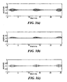
- Fig. 4 stimulation sequences of the new approach are directly compared to the corresponding CIS-sequences at 1.5kpps.
- the CSSS-based sequence in Fig. 4(b) clearly represents the temporal fine structure plus the envelope information of the band pass output shown in Fig. 4(a)
- the CIS-pattern in Fig. 4(c) is obtained by sampling the envelope, and thus any temporal fine structure is removed.
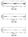
- Figs. 5(b) and (c) are derived by envelope sampling with single pulses. However, in this frequency range, neurons are only able to track the envelope signals, but cannot follow the stimulation frequency itself.
- the difference between traces 2 and 3 is the sampling rate, which is considerably lower for CIS.
- channel interaction in connection with pulsatile stimulation strategies occurs as a spatial and as a temporal effect. Temporal interaction could be further separated into “physical” and “physiological” interaction.
- Physical temporal channel interaction means that the electrical properties of a stimulation pulse in the nervous tissue are biased by its predecessor, e.g., due to residual charge stored in the tissue and in the membrane capacitances of the neurons. Physical temporal interaction is suppressed to a great extent by using symmetrical, biphasic stimulation pulses. Most of the charge delivered to the excitable tissue during the first phase of a stimulation pulse is removed during the second. However, since the tissue shows some capacitative behavior, some residual charge remains after the end of the stimulation pulse and possibly may bias the subsequent stimulation pulse. Theoretically, triphasic pulses (with zero net charge) would help to further reduce physical temporal channel interaction.
- Physiological interaction means effects associated with the refractory properties of the neurons.
- CIS strategy the influence of spatial channel interaction is reduced by employing pulses which are not overlapping in time (interleaved sampling).
- the conductivity in the scala tympani here leads to a considerable spread and a de-focusing of the electrical field at the site of the excitable tissue.
- an additional effect occurs, if simultaneous stimulation of two or more electrodes against a remote ground electrode is considered.
- the conductivity represents a shunt conductance between active electrodes, which in general results in a temporal mixture of constructive and destructive superposition of electrical fields at the position of the neurons. For example, if two simultaneous stimulation channels produce currents with equal amplitudes, but different signs, most of the current will flow through the shunt conductance and will not reach the intended neurons.
- Sign-correlation means that the signs of the phases of simultaneous stimulation pulses are equal. This ensures that the sum of the magnitudes of the single stimulation currents is forced to flow into the reference electrode. Thus, at the site of the excitable neurons, only constructive superposition of currents is possible.
- the idea here is to modify stimulation currents such that at least the potentials at the position of the electrodes are equal as in the case of single channel stimulation.
- coefficients of matrix H reflect spatial channel interaction.
- a coefficient at row i and column j describes the fraction of the single channel potential caused by electrode #j at the position of electrode #i.
- H -1 is the inverse matrix of H.
- matrix H -1 in general is a tri-diagonal matrix with non-zero elements only in the main-, the upper and lower neighboring diagonals (see Appendix).
- a space constant ⁇ 3.6mm is assumed.
- the y-axis is normalized to the maximum potential of electrode #4 at position 4.
- Fig.6(a) depicts the single voltage distributions in the scala tympani as responses to single electrode currents at different amplitudes.
- the electrodes are activated sequentially, and thus each of the single potential distribution applies for the duration of a pulse phase. Assuming a pulse repetition rate of 1.5kppulses/s for each channel, the overall time necessary to present all six distributions is 666 ⁇ s, which is just about the duration of the absolute refractory period (t a ⁇ 700 ⁇ s). This allows the following rough approximation: for CIS, due to physiological channel interaction, the "effective" stimulation pattern is the contour of the single potential distributions, as shown in Fig.6(b) , (asterisks).
- This is in contradiction to the concept of sign-correlated pulses, which requires the same sign for all simultaneously activated channels.
- the 5 th row and 5 th column of Matrix H are deleted, resulting in a modified 5x5-Matrix H mod .
- the envelope sampling sequences for each channel are chosen as shown in Fig.1(a) .
- the spatial channel interaction is taken into account.
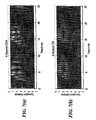
- the stimulation pattern reflects the temporal fine structure.
- the center frequency of channel #2 is represented in the temporal waveform.
- a so-called "hole-effect" can be observed: if electrode #2 is not active, i.e., if the output of filter channel #2 is negative, then other spectral maxima are not masked (due to spatial channel interaction) and appear in the waveform.
- the CIS system, Fig. 7(b) is based on an overall sampling rate of 10kpps, resulting in a rate of 1667pps per channel for the 6-channel system.
- Envelope detection for each channel is achieved with a full-wave rectifier and a low pass filter with a cut off frequency of 400Hz (Butterworth filter of 2 nd order), respectively. Obviously, the envelope signal is sampled and presented, but the temporal fine structure is lost.
- One data word consists of 16 bits, including START and STOP bits.
- the two special bits SPEC1 and SPEC0 represent a low rate information channel and are used for the initialization of the implant.
- the implant is permanently supplied with data defining the amplitude distributions and pules repetition rate of the normalized CSSS's, as well as data defining the reference current levels for each channel. These data are stored in particular implant memories.
- safety bits e.g., for cyclic redundancy check (CRC)
- CRC cyclic redundancy check
- the four address bits ADD3-ADDO define the channel address, and bits W7-W0 the weighting factor of the associated CSSS.
- the repetition rate of the Tab.1: Data word Bit # Definition 1 START 2 ADD3 3 ADD2 4 ADD1 5 ADD0 6 W7 7 W6 8 W5 9 W4 10 W3 11 W2 12 W1 13 W0 14 SPEC1 15 SPEC0 16 STOP CSSS's is comparatively low, especially at the low frequency channels. It is not necessary to transmit the amplitudes of the individual ultra-high rate pulses, since the amplitude distributions are already stored in the implant.
- a bit rate of 600kbit/s for a practical cochlear implant is sufficient for complete information transfer.
- this is a moderate rate as compared to the case, if each stimulation pulse has to be defined independently.
- a frame-rate of 10kpps of simultaneous stimulation pulses and a data word of 16bit per pulse an overall bit rate of 1920kbit/s results.
- Such a bit rate is almost impossible to realize with a inductive link system at reasonable power consumption.
- the correction of the amplitudes due to spatial channel interaction has to be performed for each simultaneous stimulation frame.
- CSSS stimulation approach may be summarized as follows.
Abstract
characterised in that:
the stimulator means associates each electrode in the multi-channel electrode array with a channel specific sampling sequence having a predefined duration, amplitude, and plurality of pulses, each electrode associated with a different channel specific sampling sequence, and wherein the stimulator means applies a weighting factor to each channel specific sampling sequence so as to create a weighted channel specific sampling sequence for each electrode in the electrode array, the weighting factor based, at least in part, on an acoustic representative electrical signal is disclosed.


Description
- This application claims priority from United States provisional patent application serial number
60/150,773 filed August 26,1999 - The present invention relates to electrical nerve stimulation, and more particularly, electrostimulation of the nerve based on channel specific sampling sequences.
- Cochlear implants (inner ear prostheses) are a possibility to help profoundly deaf or severely hearing impaired persons. Unlike conventional hearing aids, which just apply an amplified and modified sound signal, a cochlear implant is based on direct electrical stimulation of the acoustic nerve. The intention of a cochlear implant is to stimulate nervous structures in the inner ear electrically in such a way that hearing impressions most similar to normal hearing are obtained.
- A cochlear prosthesis essentially consists of two parts, the speech processor and the implanted stimulator. The speech processor contains the power supply (batteries) of the overall system and is used to perform signal processing of the acoustic signal to extract the stimulation parameters. The stimulator generates the stimulation patterns and conducts them to the nervous tissue by means of an electrode array which usually is positioned in the scala tympani in the inner ear. The connection between speech processor and stimulator is established either by means of a radio frequency link (transcutaneous) or by means of a plug in the skin (percutaneous).
- At present, the most successful stimulation strategy is the so called "continuous-interleaved-sampling strategy" (CIS), as described by Wilson B. S., Finley C. C., Lawson D. T., Wolford R. D., Eddington D. K., Rabinowitz W. M., "Better speech recognition with cochlear implants," Nature, vol. 352, 236 - 238 (July 1991) [hereinafter Wilson et al., 1991], which is incorporated herein by reference. Signal processing for CIS in the speech processor involves the following steps:
- (1) splitting up of the audio frequency range into spectral bands by means of a filter bank,
- (2) envelope detection of each filter output signal,
- (3) instantaneous nonlinear compression of the envelope signal (map law).
- According to the tonotopic organization of the cochlea, each stimulation electrode in the scala tympani is associated with a band pass filter of the external filter bank. For stimulation, symmetrical biphasic current pulses are applied. The amplitudes of the stimulation pulses are directly obtained from the compressed envelope signals (step (3) of above). These signals are sampled sequentially, and the stimulation pulses are applied in a strictly non-overlapping sequence. Thus, as a typical CIS-feature, only one stimulation channel is active at one time. The overall stimulation rate is comparatively high. For example, assuming an overall stimulation rate of 18kpps, and using an 12 channel filter bank, the stimulation rate per channel is 1.5kpps. Such a stimulation rate per channel usually is sufficient for adequate temporal representation of the envelope signal.
- The maximum overall stimulation rate is limited by the minimum phase duration per pulse. The phase duration cannot be chosen arbitrarily short, because the shorter the pulses, the higher the current amplitudes have to be to elicit action potentials in neurons, and current amplitudes are limited for various practical reasons. For an overall stimulation rate of 18kpps, the phase duration is 27µs, which is at the lower limit.
- Each output of the CIS band pass filters can roughly be regarded as a sinusoid at the center frequency of the band pass filter, which is modulated by the envelope signal. This is due to the quality factor Q = 3 of the filters. In case of a voiced speech segment, this envelope is approximately periodic, and the repetition rate is equal to the pitch frequency.
- In the current CIS-strategy, the envelope signals only are used for further processing, i.e., they contain the entire stimulation information. For each channel, the envelope is represented as a sequence of biphasic pulses at constant repetition rate. As a characteristic feature of CIS, this repetition rate (typically 1.5kpps) is equal for all channels, and there is no relation to the center frequencies of the individual channels. It is intended that the repetition rate is not a temporal cue for the patient, i.e., it should be sufficiently high, so that the patient does not percept tones with a frequency equal to the repetition rate. The repetition rate is usually chosen greater than at twice the bandwidth of the envelope signals (Nyquist theorem).
- In accordance with one aspect of the invention, electrodes in a multichannel electrode array are activated using channel specific sampling sequences. A channel specific sampling sequence for each electrode is defined, having a particular duration, amplitude, and number of pulses. A weighting factor is applied to the channel specific sampling sequence, creating a weighted channel specific sampling sequence. Each electrode in the multichannel electrode array is then simultaneously activated using sign-correlated pulses, the sign-correlated pulses based on parameters of spatial channel interaction, non-linear compression, and each electrode's weighted channel specific sampling sequence.
- In accordance with other related emodiments, the electrodes stimulate the acoustic nerve. The multichannel electrode array can be used in a monopolar electrode configuration having a remote ground. The pulse amplitudes can be derived by sampling a signal waveform, for example, one half the period of a sinusoid between 0 and π, or one quarter of a sinusoid between 0 and π/2 so that the amplitude distribution is monotonically increasing. Symmetrical biphasic current pulses can be used to sample the signal waveform. The channel specific sampling sequence pulse rate may be between 5-10 kpps. The parameters of spatial channel interaction can be based on a single electrode model having exponential decays of the potentials at both sides of the electrode, the sign-correlated pulses having amplitudes which are calculated using properties of a tri-diagonal matrix. The multichannel electrode array can be in a cochlear implant, whereby the weighting factor is transmitted to the cochlear implant. Start and stop bits, and addresses associated with an electrode can also be transmitted to the cochlear implant.
- In accordance with another embodiment of the invention, electrodes in a multichannel electrode array are activated using channel specific sampling sequences by applying an acoustic signal to a bank of filters, each filter in the bank of filters associated with a channel having an electrode. A weighting factor is derived for each channel based on the output of each channel's filter. The weighting factor is then applied to a channel specific sampling sequence having a particular duration, amplitude and number of pulses, creating a weighted channel specific sampling sequence. Each channel's electrode is simultaneously activated using sign-correlated pulses, the sign-correlated pulses based on the weighted channel specific sampling sequence, non-linear compression, and parameters of spatial channel interaction.
- In accordance with other related embodiments, the electrodes can stimulate the acoustic nerve. The weighting factor can be derived by rectifying the output of each filter, and then determining the maximum amplitude of each half-wave in the rectified signal. The multichannel electrode array can used a monopolar electrode configuration having a remote ground. The pulse amplitudes of the channel specific sampling sequence can be derived by sampling a signal waveform, such as one half the period of a sinusoid between 0 and π, or one quarter of a sinusoid so that the amplitude distribution is monotonically increasing. Symmetrical biphasic current pulses can be used to sample the waveform. Each channel filter can be a bandpass filter. The duration and number of pulses in the channel specific sampling sequence can then be derived from the center frequency of the channel's bandpass filter. For example, the duration of the channel specific sampling sequence can be one half of the period of the bandpass filter's center frequency. The parameters of spatial channel interaction can be based on a single electrode model having exponential decays of the potentials at both sides of the electrode, the sign-correlated pulses having amplitudes determined by using properties of a tri-diagonal matrix. The multichannel electrode array can be in a cochlear implant, whereby the weighting factor is transmitted to the cochlear implant. Start and stop bits, and addresses associated with an electrode can also be transmitted to the cochlear implant.
- In accordance with another embodiment of the invention, electrodes are simultaneously activated in a multichannel electrode array using channel specific sampling sequences. Sign-correlated pulses are used. The amplitudes of the sign-correlated pulses are calculated by taking into account parameters of spatial channel interaction. In calculating the amplitudes of the sign-correlated pulses a single electrode model having exponential decays of the potentials at both sides of the electrode can be used. The amplitudes of the sign-correlated pulses can be calculated using properties of a tri-diagonal matrix.
- In accordance with another embodiment of the invention, channel specific sampling sequence having a pulse descriptive characterization are defined. The channel specific sampling sequence is used to activate electrodes in a multichannel electrode array, each filter in a bank of filters associated with a channel having an electrode. Pulse amplitudes of the channel sampling sequence are derived by sampling a signal waveform. The duration and number of pulses of the channel specific sampling sequence are derived from a frequency associated with the channel's filter.
- In accordance with other related embodiments, the sampling is of a half period of a sinusoid between 0 and π. The sampling can also be of a quarter period of a sinusoid between 0 and π/2, so that pulse amplitude distribution monotonically increases. The sampling can use biphasic current pulses. Each filter can be a bandpass filter. The duration and number of pulses in the channel specific sampling sequence can be derived from the center frequency of the channel's bandpass filter. The duration of the channel specific sampling sequence can be one half of the period of the bandpass filter's center frequency.
- In another embodiment of the invention, a weighting factor for a channel specific sampling sequence is derived, the channel specific sampling sequence being used to activate electrodes in a multichannel electrode array, each filter in a bank of filters associated with a channel having an electrode. The output of each filter is rectified, creating a half-wave rectified signal. The maximum amplitude of each half-wave in the half-wave rectified signal is then determined.
- The foregoing features of the invention will be more readily understood by reference to the following detailed description, taken with reference to the accompanying drawings, in which:
-
Figure 1 shows channel specific sampling sequences (CSSS) for two 6-channel systems utilizing biphasic pulses at 10kpp/ and phase duration of 25µs- a. derived from a sinusoid within [0 π]
- b. derived from a sinusoid within [0 π/2], amplitudes monotonically increasing
-
Figure 2 shows stimulation with channel specific sampling sequences (CSSS)- a. Band pass filter output signal (653Hz - 876Hz)
- b. Half wave rectified band pass filter output
- c. Associated CSSS stimulation sequence
-
Figure 3 shows stimulation with channel specific sampling sequences (CSSS)- a. Bandpass filter output signal (3457Hz -5500Hz)
- b. Half wave rectified band pass filter output
- c. Associated CSSS stimulation sequence
-
Figure 4 shows a comparison of stimulation patterns between CSSS and CIS- a. Band pass filter output signal (653Hz - 876Hz)
- b. CSSS stimulation sequence
- c. CIS stimulation sequence (envelope sampling with single pulses at 1.5 kpps)
-
Figure 5 shows a comparison of stimulation patterns between CSSS and CIS- a. Band pass filter output signal (3457Hz - 5500Hz)
- b. CSSS stimulation sequence
- c. CIS stimulation sequence (envelope sampling with single pulses at 1.5 kpps)
-
Figure 6 shows estimated potential distributions in the scala tympani (λ = 3.6mm, d = 2.8mm)- a. Responses to single channel activation
- b. Effective Potential Distributions (asterisks for CIS, circles for CSSS)
-
Figure 7 shows a comparison of overall stimulation patterns between CSSS and CIS (electrode distance: d = 2.8mm, space constant: λ =3.6 mm)- a. 6-channel CSSS
- b. 6-channel CIS
- A cochlear implant with stimulation patterns containing enhanced temporal information, especially in the low frequency range up to 1kHz, is described. It is known from literature that the neurons are able to track analogue electrical sinusoidals up to about 1kHz. This ability is not exploited in the present CIS strategy, since the sampling rate is too low to represent high frequency envelope waveforms.
- The stimulation strategy utilized is based on channel specific sampling sequences (CSSS). The basic idea is to a apply a stimulation pattern, where a particular relationship to the center frequencies of the filter channels is preserved, i.e., the center frequencies are represented in the temporal waveforms of the stimulation patterns, and are not fully removed, as in CIS.
- Each stimulation channel is associated with a particular CSSS, which is a sequence of ultra-high-rate biphasic pulses (typically 5-10kpps). Each CSSS has a distinct length (number of pulses) and distinct amplitude distribution. The length of a CSSS is derived from the center frequency of the associated band pass filter. A CSSS associated with a lower filter channel is longer than a CSSS associated with a higher filter channel. Typically, it is one half of the period of the center frequency. The amplitude distribution can be adjusted to patient specific requirements. For convenience, the amplitude of the maximum biphasic pulse within a CSSS is normalized to one. For illustration, two examples for a 6-channel system are shown. In
Fig.1(a) , the CSSS's are derived by sampling one half of a period of a sinusoid, whose frequency is equal to the center frequency of the band pass filter (center frequencies at 440Hz, 696Hz, 1103Hz, 1745Hz, 2762Hz, and 4372Hz). Sampling is achieved by means of biphasic pulses at a rate of 10kpps and a phase duration of 25µs. Forchannels # 5 and #6, one half of a period of the center frequencies is too short to give space for more than one stimulation pulse, i.e., the "sequences" consist of only one pulse, respectively. InFig.1(b) the sequences are derived by sampling one quarter of a sinusoid with a frequency, which is half the center frequency of the band pass filters. These CSSS's have about the same durations as the CSSS's inFig.1(a) respectively, but the amplitude distribution is monotonically increasing. Such monotonic distributions might be advantageous, because each pulse of the sequence can theoretically stimulate neurons at sites which cannot be reached by its predecessors. This is a pure "geometric" effect, and could possibly result in a broader temporal distribution of the firing pattern of the neurons. - An example of a stimulation pattern based on CSSS is depicted in
Fig.2 for a voiced speech segment. For reasons of clarity, the influence of spatial channel interaction is neglected here. In addition, and in the following text, the instantaneous non-linear compression is omitted for convenience, however it is realized that such conversion is required for actual stimulation patterns.Fig. 2(a) shows the output of a band pass filter (cut off frequencies at 553Hz and 876Hz).Fig. 2(b) illustrates the half-wave rectified version of the signal. InFig. 2(c) , each half-wave-pulse is replaced by a CSSS, where the amplitude of the maximum pulse within each CSSS is equal to the maximum of the associated half-wave-pulse. Thus,Fig. 3 represents a sequence of weighted and time-shifted CSSS's. The CSSS used for this example is equal to the CSSS inFig. 1(a) for channel CH2, and for convenience, each biphasic pulse is represented as a single vertical line. - An example of a stimulation pattern based on CSSS for a higher frequency channel is shown in
Fig. 3 (the input speech segment is the same as forFig. 2 , spatial channel interaction is neglected again). The band pass filter here selects a range between 3475Hz and 5500Hz. With a center frequency of 4273Hz, the period is 229µs, and sampling one half of this period gives space for only one pulse (cf. CSSS as shown inFig. 1 for channel CH5). Here, the envelope sampling is reduced to a sampling with single pulses at a rate equal to about the center frequency of 4273Hz. - In
Fig. 4 stimulation sequences of the new approach are directly compared to the corresponding CIS-sequences at 1.5kpps. The CSSS-based sequence inFig. 4(b) clearly represents the temporal fine structure plus the envelope information of the band pass output shown inFig. 4(a) , whereas the CIS-pattern inFig. 4(c) is obtained by sampling the envelope, and thus any temporal fine structure is removed. At a stimulation channel at higher frequencies,Figs. 5(b) and (c) are derived by envelope sampling with single pulses. However, in this frequency range, neurons are only able to track the envelope signals, but cannot follow the stimulation frequency itself. The difference betweentraces - For the practical implementation of the new stimulation approach as described above it is necessary to utilize simultaneous stimulation techniques. Interleaved sampling as employed in CIS is impractical here, since this would require stimulation pulses with a phase duration of only few microseconds.
- In the following, the most important mechanisms of channel interaction involved with cochlear implants are summarized.
- In principle, channel interaction in connection with pulsatile stimulation strategies occurs as a spatial and as a temporal effect. Temporal interaction could be further separated into "physical" and "physiological" interaction.
- Spatial channel interaction means that there is considerable geometric overlapping of electrical fields at the location of the excitable nervous tissue, if different stimulation electrodes (positioned in the scala tympani) are activated. Thus, neglecting temporal channel interaction, the same neurons can be activated if different electrodes are stimulated. Stimulation of a particular electrode against a remote ground electrode (monopolar stimulation) causes an electrical potential within the scala tympani which can roughly be described by two decaying exponentials at both sides of the electrode, and the space constant (in humans) is typically λ = 3.6mm, as described by Wilson B. S., Finley C. C., Zerbi M., and Lawson D. T., "Speech processors for auditory prostheses," Seventh Quarterly Progress Report, Feb.1st through April 30th, 1994, NIH Contract N01-DC-2-2401 [hereinafter Wilson et al., 1994], which is incorporated herein by reference. This type of channel interaction is first of all due to the conductive fluids and tissues surrounding the stimulation electrode array. A similar space constant is also obtained by simulation, if a simple model of a cochlea composed of exclusively ohmic resistors is assumed, as described by Kral A., Hartmann R., Mortazavi D., and Klinke R., "Spatial resolution of cochlear implants: the electrical field and excitation of auditory afferents," Hearing Research 121, pp. 11-28, (1998), which is incorporated herein by reference. This model allows a rough quantitative computation of the electrical potentials within the scala tympani, as well as at the position of excitable neurons.
- Physical temporal channel interaction means that the electrical properties of a stimulation pulse in the nervous tissue are biased by its predecessor, e.g., due to residual charge stored in the tissue and in the membrane capacitances of the neurons. Physical temporal interaction is suppressed to a great extent by using symmetrical, biphasic stimulation pulses. Most of the charge delivered to the excitable tissue during the first phase of a stimulation pulse is removed during the second. However, since the tissue shows some capacitative behavior, some residual charge remains after the end of the stimulation pulse and possibly may bias the subsequent stimulation pulse. Theoretically, triphasic pulses (with zero net charge) would help to further reduce physical temporal channel interaction.
- Physiological interaction means effects associated with the refractory properties of the neurons. Following Wilson et al, 1994, a recovery function r(t) can be defined as


- The influence of physiological temporal interaction on speech understanding is currently investigated at various research centers worldwide. At the moment, it seems that the similarity between neural excitation patterns due to electrical stimulation and natural excitation patterns can be enhanced, if very high stimulation rates are employed (> 3kpps per channel, as described by Matsuoka A. J., "Compound action potentials evoked by electrical pulse trains: effects of stimulus parameters on response patterns," thesis at University of Iowa, (July 1998), which is incorporated herein by reference. High rates may mimic membrane noise (spontaneous activity) and thereby keep different neurons in different refractory states. If this is the case, it can be expected that the ensemble spiking patterns can reflect the envelope of amplitude modulated electrical pulse sequences up to considerably higher frequencies, and thus more temporal information can be provided to the brain.
- In CIS strategy, the influence of spatial channel interaction is reduced by employing pulses which are not overlapping in time (interleaved sampling). The conductivity in the scala tympani here leads to a considerable spread and a de-focusing of the electrical field at the site of the excitable tissue. However, an additional effect occurs, if simultaneous stimulation of two or more electrodes against a remote ground electrode is considered. Here the conductivity represents a shunt conductance between active electrodes, which in general results in a temporal mixture of constructive and destructive superposition of electrical fields at the position of the neurons. For example, if two simultaneous stimulation channels produce currents with equal amplitudes, but different signs, most of the current will flow through the shunt conductance and will not reach the intended neurons. This additional effect can be removed, if "sign-correlated" pulses are employed. Sign-correlation here means that the signs of the phases of simultaneous stimulation pulses are equal. This ensures that the sum of the magnitudes of the single stimulation currents is forced to flow into the reference electrode. Thus, at the site of the excitable neurons, only constructive superposition of currents is possible.
- The injection of a current by means of a single active electrode into the scala tympani causes a particular voltage in the tissue just close to the electrode (measured against the remote reference electrode), and an exponential decay at both sides of the electrode. The space constant typically is λ = 3.6mm, as described by Wilson et al, 1994. Assuming a linear and pure ohmic system, the injection of currents in more than one electrode causes a superposition of the potential distributions due to the single currents.
- The idea here is to modify stimulation currents such that at least the potentials at the position of the electrodes are equal as in the case of single channel stimulation. Assuming N channels, the single channel (non-simultaneous) current amplitudes xn (n = 1-N) and the amplitudes yn (n = 1-N) for simultaneous channels are related via the following set of linear equations:


- The coefficients of matrix H reflect spatial channel interaction. A coefficient at row i and column j describes the fraction of the single channel potential caused by electrode #j at the position of electrode #i.
- For given amplitudes xn, it follows

- An example is shown in
Fig.6 for six electrodes (N = 6). The x-axis is normalized to a distance d = 2.8mm between the electrodes, i.e., the electrodes are atpositions 1 to 6. A space constant λ = 3.6mm is assumed. The y-axis is normalized to the maximum potential ofelectrode # 4 atposition 4.Fig.6(a) depicts the single voltage distributions in the scala tympani as responses to single electrode currents at different amplitudes. - For CIS, the electrodes are activated sequentially, and thus each of the single potential distribution applies for the duration of a pulse phase. Assuming a pulse repetition rate of 1.5kppulses/s for each channel, the overall time necessary to present all six distributions is 666µs, which is just about the duration of the absolute refractory period (ta ≈ 700µs). This allows the following rough approximation: for CIS, due to physiological channel interaction, the "effective" stimulation pattern is the contour of the single potential distributions, as shown in
Fig.6(b) , (asterisks). - For
Fig.6(b) (circles), the amplitudes yn (n =1-6) for simultaneous stimulation are computed by means of (4). As demanded, the potentials coincide at the electrode positions. Obviously, the peaks obtained by taking the contour of the non-simultaneous potential distributions CIS are more pronounced than with CSSS. Unfortunately, not all amplitude distributions xn > 0 yield solutions yn with positive elements for all n. This is in contradiction to the principle of "sign-correlation", and requires to compute a modified vector y'n, which contains only non-negative elements (see Appendix). - For CIS, the electrodes are activated sequentially, and thus each of the single potential distribution applies for the duration of a pulse phase. Assuming a pulse repetition rate of 1.5kppulses/s for each channel, the overall time necessary to present all six distributions is 666µs, which is just about the duration of the absolute refractory period (a = 700µs). This allows the following rough approximation: for CIS, due to physiological channel interaction, the "effective" stimulation pattern is the contour of the single potential distributions, as shown in
Fig. 6(b) , (asterisks). - If amplitudes Ii,CSSS (i =1-6) are computed by means of (4) for a distribution of Ii (i = 1-6) as in
Fig.6 , one of the current amplitude, I5,CSSS, is negative. This is in contradiction to the concept of sign-correlated pulses, which requires the same sign for all simultaneously activated channels. In this case, e.g., the 5th row and 5th column of Matrix H are deleted, resulting in a modified 5x5-Matrix Hmod. A distribution Ii,CSSS,mod with only 5 simultaneous currents is obtained by (1) computing the inverse matrix H-1 mod , and (2) multiplying H-1 mod with vector I¡ (i = 1,2,3,4, and 6). The resulting potential distribution is shown inFig. 6(b) , (circles). As demanded, the potentials coincide at thepositions - For the CSSS system,
Fig. 7(a) , the envelope sampling sequences for each channel are chosen as shown inFig.1(a) . To obtain the actual stimulation signals for each channel, the spatial channel interaction is taken into account. As expected, the stimulation pattern reflects the temporal fine structure. In particular, the center frequency ofchannel # 2 is represented in the temporal waveform. A so-called "hole-effect" can be observed: ifelectrode # 2 is not active, i.e., if the output offilter channel # 2 is negative, then other spectral maxima are not masked (due to spatial channel interaction) and appear in the waveform. - The CIS system,
Fig. 7(b) is based on an overall sampling rate of 10kpps, resulting in a rate of 1667pps per channel for the 6-channel system. Envelope detection for each channel is achieved with a full-wave rectifier and a low pass filter with a cut off frequency of 400Hz (Butterworth filter of 2nd order), respectively. Obviously, the envelope signal is sampled and presented, but the temporal fine structure is lost. - Although based on highly synchronous stimulation, the CSSS approach is well suited for an implementation in a practical cochlear implant system. The information transfer rate from the speech processor to the implant can be kept comparatively low. An example of a data word for a 12-channel CSSS system is shown in Tab.1.
- One data word consists of 16 bits, including START and STOP bits. The two special bits SPEC1 and SPEC0 represent a low rate information channel and are used for the initialization of the implant. The implant is permanently supplied with data defining the amplitude distributions and pules repetition rate of the normalized CSSS's, as well as data defining the reference current levels for each channel. These data are stored in particular implant memories. Besides, safety bits (e.g., for cyclic redundancy check (CRC)) are transmitted. Note that for proper operation of the implant, the information defining the normalized
CSSS's and the reference current levels theoretically have to be transmitted only once. - The four address bits ADD3-ADDO define the channel address, and bits W7-W0 the weighting factor of the associated CSSS. The repetition rate of the
Tab.1: Data word Bit # Definition 1 START 2 ADD3 3 ADD2 4 ADD1 5 ADD0 6 W7 7 W6 8 W5 9 W4 10 W3 11 W2 12 W1 13 W0 14 SPEC1 15 SPEC0 16 STOP - Assuming an input analysis range between 350Hz - 5500Hz for a 12-channel system, and a logarithmic spacing of the band pass filter ranges, results in center frequencies 393Hz, 494Hz, 622Hz, 782Hz, 983Hz, 1237Hz, 1556Hz, 1958Hz, 2463Hz, 3098Hz, 3898Hz, and 49036Hz. Thus, the average CSSS-repetition rate is equal to the sum of the center frequencies, i.e., RCSSS = 22386Hz. This is equal to the average data word repetition rate Rdataword. The resulting average overall bit rate is Rbit = 16Rdataword ≈ 358kbit/s. Thus, a bit rate of 600kbit/s for a practical cochlear implant is sufficient for complete information transfer. However, this is a moderate rate as compared to the case, if each stimulation pulse has to be defined independently. Here, assuming a frame-rate of 10kpps of simultaneous stimulation pulses and a data word of 16bit per pulse, an overall bit rate of 1920kbit/s results. Such a bit rate is almost impossible to realize with a inductive link system at reasonable power consumption.
- Within the implant, the correction of the amplitudes due to spatial channel interaction has to be performed for each simultaneous stimulation frame.
- In summary, the CSSS stimulation approach may be summarized as follows.
- (1) For stimulation, a multichannel electrode array within the scala tympani and a remote ground electrode is used (monopolar electrode configuration). The basic stimulation waveform is a symmetrical, biphasic pulse.
- (2) Stimulation involves simultaneous activation of electrodes in the scala tympani employing sign-correlated pulses. Sign-correlated means that if two or more pulses occur simultaneously at different electrodes, positive and negative phases are absolute synchronous in time.
- (3) The amplitudes of the sign-correlated pulses are estimated by taking into account parameters of spatial channel interaction. Assuming that a single electrode causes exponential decays of the potentials at both sides of the electrode allows a computationally efficient calculation of the pulse amplitudes, since a tri-diagonal matrix is involved.
- (4) Processing of the acoustic signal involves a filter bank for splitting up the audio frequency range (similar to CIS). According to the tonotopic organization of the scala tympani, each band pass filter is associated with a stimulation electrode.
- (5) Each stimulation channel is associated with a normalized, channel specific sampling sequence (CSSS) of ultra-high-rate pulses. Typically, rates between 5-10kpps are employed. For each channel, the CSSS has different length and different amplitude distribution. The maximum amplitude of a normalized CSSS is one.
- (6) The length of a CSSS is derived from the center frequency of the associated band pass filter. Typically, it is one half of the period of the center frequency. For example, a band pass center frequency of 500Hz results in a CSSS-length of 1ms comprising 10 pulses. (assuming a ultra-high-rate of 10kpps).
- (7) The amplitude distribution of a CSSS is chosen for optimum performance with respect to mimicking membrane noise. As many neurons as possible shall be kept in different refractory states.
- Although various exemplary embodiment of the invention have been disclosed, it should be apparent to those skilled in the art that various changes and modifications can be made which will achieve some of the advantages of the invention without departing from the true scope of the invention. These and other obvious modifications are intended to be covered by the claims that follow.


- Certain aspects of the inventive concept are indicated below:
- 1. A method of activating electrodes in a multichannel electrode array using channel specific sampling sequences, the method comprising:
- a. defining for each electrode a channel specific sampling sequence having a selected duration, amplitude, and number of pulses;
- b. applying a weighting factor to each channel specific sampling sequence, creating a weighted channel specific sampling sequence for each electrode; and
- c. simultaneously activating each electrode using sign-correlated pulses, the sign-correlated pulses being based on:
- i. parameters of spatial channel interaction;
- ii. each electrode's weighted channel specific sampling sequence; and
- iii. non-linear compression.
- 2. A method according to 1, wherein the electrodes stimulate the acoustic nerve.
- 3. A method according to 1, wherein the multichannel electrode array uses a monopolar electrode configuration having a remote ground.
- 4. A method according to 1, wherein the channel specific sampling sequence pulse amplitudes are derived by sampling a signal waveform.
- 5. A method according to 4, wherein the sampling is of a half period of a sinusoid between 0 and π.
- 6. A method according to 4, wherein the sampling is of a quarter period of a sinusoid between 0 and π/2 so that pulse amplitude distribution monotonically increases.
- 7. A method according to 4, wherein the sampling uses symmetrical biphasic current pulses.
- 8. A method according to 1, wherein the channel specific sampling sequence has a pulse rate between 5-10 kpps.
- 9. A method according to 1, wherein the parameters of spatial channel interaction are based on a single electrode model having exponential decays of the potentials at both sides of the electrode.
- 10. A method according to 9, wherein the sign-correlated pulses have amplitudes determined by using properties of a tri-diagonal matrix.
- 11. A method according to 1, wherein the multichannel electrode array is in a cochlear implant and the weighting factor is transmitted to the cochlear implant.
- 12. A method according to 11, wherein start and stop bits are transmitted to the cochlear implant, along with the weighting factor.
- 13. A method according to 11, wherein addresses associated with an electrode are transmitted to the cochlear implant, along with the weighting factor.
- 14. A method of activating electrodes in a multichannel electrode array using channel specific sampling sequences, the method comprising:
- a. applying an acoustic representative electrical signal to a bank of filters, each filter in the bank of filters associated with a channel having an electrode;
- b. deriving a weighting factor for each channel from the output of each channel filter;
- c. applying the weighting factor to a channel specific sampling sequence having a selected duration, amplitude and number of pulses, creating a weighted channel specific sampling sequence; and
- d. simultaneously activating each channel's electrode using sign-correlated pulses, the sign-correlated pulses being based on:
- i. parameters of spatial channel interaction;
- ii. each electrode's weighted channel specific sampling sequence; and
- iii. non-linear compression.
- 15. A method according to 14, wherein the electrodes stimulate the acoustic nerve.
- 16. A method according to 14, wherein deriving the weighting factor comprises:
- a. rectifying the output of each filter, creating a half-wave rectified signal; and
- b. determining a maximum amplitude of each half-wave in the half-wave rectified signal.
- 17. A method according to 14, wherein the multichannel electrode array uses a monopolar electrode configuration having a remote ground.
- 18. A method according to 14, wherein the pulse amplitudes of the channel specific sampling sequence are derived by sampling a signal waveform.
- 19. A method according to 18, wherein the sampling is of a half period of a sinusoid between 0 and π.
- 20. A method according to 18, wherein the sampling is of a quarter period of a sinusoid between 0 and π/2 so that pulse amplitude distribution monotonically increases
- 21. A method according to 18, wherein the sampling uses symmetrical biphasic current pulses.
- 22. A method according to 14, wherein each filter is a bandpass filter.
- 23. A method according to 22, wherein the duration and number of pulses in the channel specific sampling sequence is derived from the center frequency of the channel's bandpass filter.
- 24. A method according to 23, wherein the duration of the channel specific sampling sequence is one half of the period of the bandpass filter's center frequency.
- 25. A method according to 14, wherein the parameters of spatial channel interaction are based on a single electrode model having exponential decays of the potentials at both sides of the electrode.
- 26. A method according to 25, wherein the sign-correlated pulses have amplitudes determined by using properties of a tri-diagonal matrix.
- 27. A method according to 14, wherein the multichannel electrode array is in a cochlear implant, and the weighting factor is transmitted to the cochlear implant.
- 28. A method according to 27, wherein start and stop bits are transmitted to the cochlear implant along with the weighting factor.
- 29. A method according to 27, wherein addresses associated with an electrode are transmitted to the cochlear implant along with the weighting factor.
- 30. A method of simultaneously activating electrodes in a multichannel electrode array using channel specific sampling sequences, the method comprising:
- a. using sign-correlated pulses; and
- b. calculating the amplitudes of the sign-correlated pulses by taking into account parameters of spatial channel interaction.
- 31. A method according to 30, wherein calculating the amplitudes of the sign-correlated pulses a single electrode model having exponential decays of the potentials at both sides of the electrode is used.
- 32. A method according to 31. wherein calculating amplitudes of the sign-correlated pulses, properties of a tri-diagonal matrix is used.
- 33. A method of defining a channel specific sampling sequence having a pulse descriptive characterization, the channel specific sampling sequence being used to activate electrodes in a multichannel electrode array, each filter in a bank of filters associated with a channel having an electrode, the method comprising:
- i. deriving pulse amplitudes of the channel sampling sequence by sampling a signal waveform;
- ii. deriving the duration and number of pulses of the channel specific sampling sequence from a frequency associated with the channel's filter.
- 34. A method according to 33, wherein the sampling is of a half period of a sinusoid between 0 and π.
- 35. A method according to 33, wherein the sampling is of a quarter period of a sinusoid between 0 and π/2 so that pulse amplitude distribution monotonically increases.
- 36. A method according to 33, wherein the sampling uses biphasic current pulses.
- 37. A method according to 33, wherein each filter is a bandpass filter.
- 38. A method according to 37, wherein the duration and number of pulses in the channel specific sampling sequence is derived from the center frequency of the channel's bandpass filter.
- 39. A method according to 37, wherein the duration of the channel specific sampling sequence is one half of the period of the bandpass filter's center frequency.
- 40. A method of deriving a weighting factor for a channel specific sampling sequence, the channel specific sampling sequence being used to activate electrodes in a multichannel electrode array, each filter in a bank of filters associated with a channel having an electrode, the method comprising:
- a. rectifying the output of each filter, creating a half-wave rectified signal; and
- b. determining a maximum amplitude of each half-wave in the half-wave rectified signal.
Claims (16)
- A system for activating electrodes, the system including a multi-channel electrode array; and stimulator means for activating electrodes in the electrode array using channel specific sampling sequences;
characterised in that:the stimulator means associates each electrode in the multi-channel electrode array with a channel specific sampling sequence having a predefined duration, amplitude, and plurality of pulses, each electrode associated with a different channel specific sampling sequence, and wherein the stimulator means applies a weighting factor to each channel specific sampling sequence so as to create a weighted channel specific sampling sequence for each electrode in the electrode array, the weighting factor based, at least in part, on an acoustic representative electrical signal. - The system according to claim 1, wherein the channel specific sampling sequence pulse amplitude is a sampled signal waveform, the signal waveform different from the acoustic representative electrical signal.
- The system according to claim 2, wherein the signal waveform is of a half period of a sinusoid between 0 and π.
- The system according to claim 2, wherein the signal waveform is a quarter period of a sinusoid between 0 and π/2, such that pulse amplitude distribution monotonically increases.
- The system according to claim 1, wherein the channel specific sampling sequence has a pulse rate between 5-10 kpps.
- The system according to claim 1, wherein the stimulator means simultaneously activates each electrode using sign-correlated pulses, the sign-correlated pulses based, at least in part, on each electrode's weighted channel specific sampling sequence.
- The system according to claim 6, wherein the stimulator means calculates the amplitudes of the sign-correlated pulses based, at least in part, on parameters of spatial channel interaction, wherein calculating the amplitudes of the sign-correlated pulses includes compensating for geometric overlapping of electric fields from each electrode.
- The system according to claim 1, further comprising speech processor means for determining the weighting factor for each channel specific sampling sequence.
- The system according to claim 8, further comprising a radio frequency link between the speech processor means and the stimulator means.
- The system according to claim 8, wherein the speech processor means includes a filter bank for receiving an acoustic representative electrical signal, each filter in the bank of filters associated with one of the electrodes in the multi-channel electrode array, and wherein the speech processor means derives the weighting factor for each electrode in the multi-channel electrode array from an associated channel filter.
- The system according to claim 10, further comprising a rectifier for rectifying the output of each filter to create a half-wave rectified signal, wherein the speech processor means determines a maximum amplitude of each half-wave in the half-wave rectified signal.
- The system according to claim 11, wherein each half-wave is replaced by the channel specific sampling sequence associated with the electrode, with the amplitude of the maximum pulse within the channel specific sampling sequence associated with the electrode equal to the maximum amplitude.
- The system according to claim 10, wherein each filter is a bandpass filter.
- The system according to claim 13, wherein the duration and number of pulses in the channel specific sampling sequence is derived from the center frequency of the channel's associated bandpass filter.
- The system according to claim 14, wherein the duration of the channel specific sampling sequence is one half of the period of the bandpass filter's center frequency.
- The system according to claim 1, wherein the system includes a cochlear implant capable of stimulating the acoustic nerve.
Applications Claiming Priority (3)
| Application Number | Priority Date | Filing Date | Title |
|---|---|---|---|
| US15077399P | 1999-08-26 | 1999-08-26 | |
| EP00958940A EP1207938B1 (en) | 1999-08-26 | 2000-08-25 | Electrical nerve stimulation based on channel specific sampling sequences |
| EP07075655A EP1854504B1 (en) | 1999-08-26 | 2000-08-25 | Electrical nerve stimulation based on channel specific sampling sequences |
Related Parent Applications (3)
| Application Number | Title | Priority Date | Filing Date |
|---|---|---|---|
| EP00958940.9 Division | 2000-08-25 | ||
| EP07075655A Division-Into EP1854504B1 (en) | 1999-08-26 | 2000-08-25 | Electrical nerve stimulation based on channel specific sampling sequences |
| EP07075655.6 Division | 2007-08-01 |
Publications (2)
| Publication Number | Publication Date |
|---|---|
| EP2208507A1 true EP2208507A1 (en) | 2010-07-21 |
| EP2208507B1 EP2208507B1 (en) | 2011-11-16 |
Family
ID=22535931
Family Applications (3)
| Application Number | Title | Priority Date | Filing Date |
|---|---|---|---|
| EP07075655A Expired - Lifetime EP1854504B1 (en) | 1999-08-26 | 2000-08-25 | Electrical nerve stimulation based on channel specific sampling sequences |
| EP10003323A Expired - Lifetime EP2208507B1 (en) | 1999-08-26 | 2000-08-25 | Electrical nerve stimulation based on channel specific sampling sequences |
| EP00958940A Expired - Lifetime EP1207938B1 (en) | 1999-08-26 | 2000-08-25 | Electrical nerve stimulation based on channel specific sampling sequences |
Family Applications Before (1)
| Application Number | Title | Priority Date | Filing Date |
|---|---|---|---|
| EP07075655A Expired - Lifetime EP1854504B1 (en) | 1999-08-26 | 2000-08-25 | Electrical nerve stimulation based on channel specific sampling sequences |
Family Applications After (1)
| Application Number | Title | Priority Date | Filing Date |
|---|---|---|---|
| EP00958940A Expired - Lifetime EP1207938B1 (en) | 1999-08-26 | 2000-08-25 | Electrical nerve stimulation based on channel specific sampling sequences |
Country Status (10)
| Country | Link |
|---|---|
| US (5) | US6594525B1 (en) |
| EP (3) | EP1854504B1 (en) |
| JP (1) | JP4819268B2 (en) |
| AT (2) | ATE533532T1 (en) |
| AU (4) | AU775268B2 (en) |
| BR (1) | BR0014147A (en) |
| CA (1) | CA2382964C (en) |
| DE (1) | DE60036875T2 (en) |
| ES (1) | ES2293921T3 (en) |
| WO (1) | WO2001013991A1 (en) |
Cited By (2)
| Publication number | Priority date | Publication date | Assignee | Title |
|---|---|---|---|---|
| US7917224B2 (en) | 1999-07-21 | 2011-03-29 | Med-El Elektromedizinische Geraete Gmbh | Simultaneous stimulation for low power consumption |
| US7937157B2 (en) | 1999-08-26 | 2011-05-03 | Med-El Elektromedizinische Geraete Gmbh | Electrical nerve stimulation based on channel specific sequences |
Families Citing this family (95)
| Publication number | Priority date | Publication date | Assignee | Title |
|---|---|---|---|---|
| US8260430B2 (en) | 2010-07-01 | 2012-09-04 | Cochlear Limited | Stimulation channel selection for a stimulating medical device |
| US8165686B2 (en) | 1999-08-26 | 2012-04-24 | Med-El Elektromedizinische Geraete Gmbh | Simultaneous intracochlear stimulation |
| AUPQ952800A0 (en) * | 2000-08-21 | 2000-09-14 | Cochlear Limited | Power efficient electrical stimulation |
| US7822478B2 (en) * | 2000-08-21 | 2010-10-26 | Cochlear Limited | Compressed neural coding |
| US9008786B2 (en) * | 2000-08-21 | 2015-04-14 | Cochlear Limited | Determining stimulation signals for neural stimulation |
| US8285382B2 (en) | 2000-08-21 | 2012-10-09 | Cochlear Limited | Determining stimulation signals for neural stimulation |
| US20050101878A1 (en) | 2001-04-18 | 2005-05-12 | Daly Christopher N. | Method and apparatus for measurement of evoked neural response |
| AUPR604801A0 (en) * | 2001-06-29 | 2001-07-26 | Cochlear Limited | Multi-electrode cochlear implant system with distributed electronics |
| US10576275B2 (en) | 2001-07-06 | 2020-03-03 | Cochlear Limited | System and method for configuring an external device using operating parameters from an implanted device |
| AU2001272189B2 (en) | 2001-07-06 | 2008-10-09 | Cochlear Limited | Configuration of implanted devices |
| EP1441679B8 (en) * | 2001-10-24 | 2018-05-30 | MED-EL Elektromedizinische Geräte GmbH | Implantable fluid delivery apparatuses and implantable electrode |
| US20070088335A1 (en) * | 2001-10-24 | 2007-04-19 | Med-El Elektromedizinische Geraete Gmbh | Implantable neuro-stimulation electrode with fluid reservoir |
| US7130694B1 (en) * | 2001-12-26 | 2006-10-31 | Advanced Bionics Corporation | Pulse skipping strategy |
| AUPS318202A0 (en) | 2002-06-26 | 2002-07-18 | Cochlear Limited | Parametric fitting of a cochlear implant |
| AU2002951218A0 (en) | 2002-09-04 | 2002-09-19 | Cochlear Limited | Method and apparatus for measurement of evoked neural response |
| AU2003294163A1 (en) * | 2002-12-02 | 2004-06-23 | Med-El Elektromedizinsche Geraete Gmbh | Fluid switch controlled trans-cutaneously via a magnetic force |
| CN1832713B (en) | 2003-08-07 | 2010-05-12 | 财团法人浜松科学技术研究振兴会 | Method for speech conversion in artificial auris interna |
| US7283876B2 (en) * | 2004-03-08 | 2007-10-16 | Med-El Elektromedizinische Geraete Gmbh | Electrical stimulation of the acoustic nerve based on selected groups |
| US8577473B2 (en) | 2004-03-08 | 2013-11-05 | Med-El Elektromedizinische Geraete Gmbh | Cochlear implant stimulation with low frequency channel privilege |
| US7941223B2 (en) * | 2004-03-08 | 2011-05-10 | Med-El Elektromedizinische Geraete Gmbh | Cochlear implant stimulation with variable number of electrodes |
| US8965520B2 (en) | 2004-06-15 | 2015-02-24 | Cochlear Limited | Automatic determination of the threshold of an evoked neural response |
| US7801617B2 (en) | 2005-10-31 | 2010-09-21 | Cochlear Limited | Automatic measurement of neural response concurrent with psychophysics measurement of stimulating device recipient |
| US8190268B2 (en) | 2004-06-15 | 2012-05-29 | Cochlear Limited | Automatic measurement of an evoked neural response concurrent with an indication of a psychophysics reaction |
| WO2006119069A2 (en) | 2005-04-29 | 2006-11-09 | Cochlear Americas | Focused stimulation in a medical stimulation device |
| DE102005030327A1 (en) * | 2005-06-29 | 2007-01-04 | Fraunhofer-Gesellschaft zur Förderung der angewandten Forschung e.V. | Apparatus, method and computer program for analyzing an audio signal |
| US20100121411A1 (en) * | 2006-02-07 | 2010-05-13 | Med-El Elektromedizinische Geraete Gmbh | Tinnitus Suppressing Cochlear Implant |
| US20070203536A1 (en) * | 2006-02-07 | 2007-08-30 | Ingeborg Hochmair | Tinnitus Suppressing Cochlear Implant |
| USRE48038E1 (en) | 2006-02-10 | 2020-06-09 | Cochlear Limited | Recognition of implantable medical device |
| AR059786A1 (en) * | 2006-03-09 | 2008-04-30 | Med El Elektromed Geraete Gmbh | CONFIGURATION OF COCLEAR IMPLANT ELECTRODE TO ELECT PHARMACOS |
| US8209018B2 (en) * | 2006-03-10 | 2012-06-26 | Medtronic, Inc. | Probabilistic neurological disorder treatment |
| US7835804B2 (en) * | 2006-04-18 | 2010-11-16 | Advanced Bionics, Llc | Removing artifact in evoked compound action potential recordings in neural stimulators |
| US8571675B2 (en) | 2006-04-21 | 2013-10-29 | Cochlear Limited | Determining operating parameters for a stimulating medical device |
| US7769467B1 (en) | 2007-01-31 | 2010-08-03 | Advanced Bionics, Llc | Level-dependent stimulation methods and systems |
| US8391993B2 (en) * | 2007-07-13 | 2013-03-05 | Cochlear Limited | Using interaction to measure neural excitation |
| CN104107505B (en) | 2007-07-13 | 2016-06-08 | Med-El电气医疗器械有限公司 | There is the electrical nerve stimulation of broad band low frequency filter |
| EP2183020B1 (en) * | 2007-08-10 | 2016-09-28 | Med-El Elektromedizinische Geräte GmbH | Pulse width adaptation for inductive links |
| CA2698886C (en) * | 2007-09-11 | 2015-02-24 | Med-El Elektromedizinische Geraete Gmbh | Simultaneous intracochlear stimulation |
| JP5550559B2 (en) * | 2007-11-09 | 2014-07-16 | メド−エル エレクトロメディジニシェ ゲラテ ゲーエムベーハー | Stimulation strategy of pulsatile transplant cochlear stimulator |
| US8894697B2 (en) * | 2011-07-22 | 2014-11-25 | Lockheed Martin Corporation | Optical pulse-width modulation used in an optical-stimulation cochlear implant |
| EP2263388B1 (en) * | 2008-04-08 | 2014-02-12 | Med-El Elektromedizinische Geräte GmbH | Electrical stimulation of the acoustic nerve with coherent fine structure |
| WO2009130609A1 (en) | 2008-04-22 | 2009-10-29 | Med-El Elektromedizinische Geraete Gmbh | Tonotopic implant stimulation |
| EP2352550B1 (en) * | 2008-09-18 | 2017-06-21 | Advanced Bionics AG | Systems of conveying fine structure information to a cochlear implant patient |
| US8532781B1 (en) * | 2008-09-18 | 2013-09-10 | Advanced Bionics, Llc | Methods and systems of generating a graphical representation of an intracochlear trajectory of electrodes |
| CN102176947A (en) * | 2008-10-07 | 2011-09-07 | Med-El电气医疗器械有限公司 | Cochlear implant sound processor for sleeping with tinnitus suppression and alarm function |
| CN102186528B (en) * | 2008-10-15 | 2013-08-07 | Med-El电气医疗器械有限公司 | Inner ear drug delivery device |
| CN102271754B (en) * | 2008-11-10 | 2014-07-16 | Med-El电气医疗器械有限公司 | Hydrogel-filled drug delivery reservoirs |
| US8565889B2 (en) * | 2008-12-08 | 2013-10-22 | Med-El Elektromedizinische Gereate GmbH | Method for fitting a cochlear implant with patient feedback |
| US8285385B2 (en) * | 2009-01-20 | 2012-10-09 | Med-El Elektromedizinische Geraete Gmbh | High accuracy tonotopic and periodic coding with enhanced harmonic resolution |
| AU2010208258B2 (en) * | 2009-01-28 | 2013-03-14 | Med-El Elektromedizinische Geraete Gmbh | Channel specific gain control including lateral suppression |
| US8954158B2 (en) * | 2009-02-05 | 2015-02-10 | Cochlear Limited | Multi-electrode channel configurations |
| EP2396076B1 (en) * | 2009-02-06 | 2016-04-20 | MED-EL Elektromedizinische Geräte GmbH | Phase triggered envelope sampler |
| US8019429B2 (en) | 2009-03-24 | 2011-09-13 | Med-El Elektromedizinische Geraete Gmbh | Carrier and envelope triggered cochlear stimulation |
| AU2010230035A1 (en) * | 2009-03-24 | 2011-11-10 | Med-El Elektromedizinische Geraete Gmbh | Musical fitting of cochlear implants |
| US8554329B1 (en) * | 2009-06-16 | 2013-10-08 | Advanced Bionics | Percutaneous cochlear implant systems and methods |
| US9393412B2 (en) | 2009-06-17 | 2016-07-19 | Med-El Elektromedizinische Geraete Gmbh | Multi-channel object-oriented audio bitstream processor for cochlear implants |
| WO2010148169A1 (en) * | 2009-06-17 | 2010-12-23 | Med-El Elektromedizinische Geraete Gmbh | Spatial audio object coding (saoc) decoder and postprocessor for hearing aids |
| US20110098784A1 (en) * | 2009-10-23 | 2011-04-28 | Med-El Elektromedizinische Geraete Gmbh | Channel-Specific Loudness Mapping for Prosthetic Hearing Systems |
| CN102917754B (en) * | 2010-03-04 | 2015-03-25 | 弗兰霍菲尔运输应用研究公司 | Electrode stimulation signal generation in a neural auditory prosthesis |
| US9031661B2 (en) * | 2010-05-18 | 2015-05-12 | Cochlear Limited | Multi-electrode channel configurations for a hearing prosthesis |
| EP2575960B1 (en) | 2010-05-28 | 2017-01-25 | Advanced Bionics AG | Systems for minimizing an effect of channel interaction in a cochlear implant system |
| US9320896B2 (en) | 2010-09-15 | 2016-04-26 | Med-El Elektromedizinische Geraete Gmbh | Accelerated fitting of cochlear implants based on current spread |
| WO2012100290A1 (en) * | 2011-01-24 | 2012-08-02 | Newsouth Innovations Pty Limited | Stimulation method for maintaining responsiveness of cells |
| WO2012103224A1 (en) * | 2011-01-25 | 2012-08-02 | Medtronic, Inc. | Target therapy delivery site selection |
| US8489194B2 (en) | 2011-02-14 | 2013-07-16 | Med-El Elektromedizinische Geraete Gmbh | Enhancing fine time structure transmission for hearing implant system |
| US8515540B2 (en) | 2011-02-24 | 2013-08-20 | Cochlear Limited | Feedthrough having a non-linear conductor |
| WO2012158486A2 (en) | 2011-05-13 | 2012-11-22 | Med-El Elektromedizinische Geraete Gmbh | Optimal model constants for simultaneous stimulation with channel interaction compensation |
| US9326075B2 (en) | 2011-10-07 | 2016-04-26 | Cochlear Limited | Flexible protocol for an implanted prosthesis |
| US9216288B2 (en) | 2011-12-22 | 2015-12-22 | Cochlear Limited | Stimulation prosthesis with configurable data link |
| US8694114B2 (en) | 2012-02-21 | 2014-04-08 | Wisconsin Alumni Research Foundation | System and method for fine-structure processing for hearing assistance devices |
| WO2013138124A2 (en) * | 2012-03-15 | 2013-09-19 | Med-El Elektromedizinische Geraete Gmbh | Using alternative stimulus waveforms to improve pitch percepts elicited with cochlear implant systems |
| PL2887997T3 (en) | 2012-08-27 | 2018-04-30 | Med-El Elektromedizinische Geräte GmbH | Reduction of transient sounds in hearing implants |
| AU2013338341B2 (en) | 2012-10-31 | 2017-08-24 | Med-El Elektromedizinische Geraete Gmbh | Temporal coding for hearing implants |
| US9320887B2 (en) | 2013-10-17 | 2016-04-26 | Med-El Elektromedizinische Geraete Gmbh | Objective allocation of implant electrode bands based on excitation spread |
| CN105813688B (en) | 2013-12-11 | 2017-12-08 | Med-El电气医疗器械有限公司 | Device for the transient state sound modification in hearing implant |
| US9999769B2 (en) * | 2014-03-10 | 2018-06-19 | Cisco Technology, Inc. | Excitation modeling and matching |
| US10173061B2 (en) * | 2014-10-08 | 2019-01-08 | Massachusetts Institute Of Technology | Methods and apparatus for stimulation of biological tissue |
| US9775997B2 (en) | 2014-10-08 | 2017-10-03 | Med-El Elektromedizinische Geraete Gmbh | Neural coding with short inter pulse intervals |
| CN106999710B (en) | 2014-12-03 | 2020-03-20 | Med-El电气医疗器械有限公司 | Bilateral hearing implant matching of ILD based on measured ITD |
| US10105539B2 (en) | 2014-12-17 | 2018-10-23 | Cochlear Limited | Configuring a stimulation unit of a hearing device |
| DE102015104614A1 (en) * | 2015-03-26 | 2016-09-29 | Med-El Elektromedizinische Geräte GmbH | Apparatus and method for electrical stimulation using a cochlear implant |
| US10814126B2 (en) | 2015-05-22 | 2020-10-27 | Cochlear Limited | Dynamic current steering |
| US9776001B2 (en) | 2015-06-11 | 2017-10-03 | Med-El Elektromedizinische Geraete Gmbh | Interaural coherence based cochlear stimulation using adapted envelope processing |
| US9770590B2 (en) | 2015-06-11 | 2017-09-26 | Med-El Elektromedizinische Geraete Gmbh | Switching hearing implant coding strategies |
| US9808624B2 (en) | 2015-06-11 | 2017-11-07 | Med-El Elektromedizinische Geraete Gmbh | Interaural coherence based cochlear stimulation using adapted fine structure processing |
| GB201511205D0 (en) | 2015-06-25 | 2015-08-12 | Sky Medical Technology Ltd | Multiple negative electrodes |
| CN107924072B (en) | 2015-08-11 | 2020-03-13 | Med-El电气医疗器械有限公司 | Multi-channel opto-electro mechanical stimulation |
| WO2017039828A1 (en) * | 2015-09-01 | 2017-03-09 | Med-El Elektromedizinische Geraete Gmbh | Rate and place of stimulation matched to instantaneous frequency |
| WO2017209742A1 (en) | 2016-05-31 | 2017-12-07 | Advanced Bionics Ag | Channel selection systems and methods that utilize fine structure information |
| US10602284B2 (en) | 2016-07-18 | 2020-03-24 | Cochlear Limited | Transducer management |
| US10743114B2 (en) * | 2016-11-22 | 2020-08-11 | Cochlear Limited | Dynamic stimulus resolution adaption |
| CN106897769A (en) * | 2017-01-20 | 2017-06-27 | 清华大学 | The neuronal messages processing method and system of window are drawn with depth time |
| CN110831658B (en) | 2017-06-28 | 2024-02-02 | Med-El电气医疗器械有限公司 | Inner olive cochlea reflex vocoding with bandwidth normalization |
| US10512775B2 (en) * | 2017-08-30 | 2019-12-24 | Cochlear Limited | Noise reduction for implantable hearing prostheses |
| EP3881564A4 (en) | 2018-11-16 | 2022-08-03 | Cochlear Limited | Focusing methods for a prosthesis |
| US20220401729A1 (en) | 2019-09-17 | 2022-12-22 | Med-El Elektromedizinische Geräte Ges.m.b.H. | Cochlear Implant Fitting Based on Neuronal Status |
Citations (4)
| Publication number | Priority date | Publication date | Assignee | Title |
|---|---|---|---|---|
| US5601617A (en) | 1995-04-26 | 1997-02-11 | Advanced Bionics Corporation | Multichannel cochlear prosthesis with flexible control of stimulus waveforms |
| US5749912A (en) | 1994-10-24 | 1998-05-12 | House Ear Institute | Low-cost, four-channel cochlear implant |
| WO1998049775A1 (en) | 1997-05-01 | 1998-11-05 | Murphy, Timothy, M. | Apparatus and method for a low power digital filter bank |
| WO1999035882A1 (en) | 1998-01-12 | 1999-07-15 | Imperial College Of Science, Technology & Medicine | Audio signal processors |
Family Cites Families (22)
| Publication number | Priority date | Publication date | Assignee | Title |
|---|---|---|---|---|
| US4284856A (en) | 1979-09-24 | 1981-08-18 | Hochmair Ingeborg | Multi-frequency system and method for enhancing auditory stimulation and the like |
| DE3008677C2 (en) * | 1980-03-06 | 1983-08-25 | Siemens AG, 1000 Berlin und 8000 München | Hearing prosthesis for electrical stimulation of the auditory nerve |
| CA1189147A (en) | 1980-12-12 | 1985-06-18 | James F. Patrick | Speech processors |
| US4823795A (en) * | 1987-03-13 | 1989-04-25 | Minnesota Mining And Manufacturing Company | Signal processor for and an auditory prosthesis having spectral to temporal transformation |
| DE3821970C1 (en) * | 1988-06-29 | 1989-12-14 | Ernst-Ludwig Von Dr. 8137 Berg De Wallenberg-Pachaly | |
| US5603726A (en) | 1989-09-22 | 1997-02-18 | Alfred E. Mann Foundation For Scientific Research | Multichannel cochlear implant system including wearable speech processor |
| US5938691A (en) * | 1989-09-22 | 1999-08-17 | Alfred E. Mann Foundation | Multichannel implantable cochlear stimulator |
| US5597380A (en) | 1991-07-02 | 1997-01-28 | Cochlear Ltd. | Spectral maxima sound processor |
| GB2259365B (en) * | 1991-09-04 | 1995-08-02 | Nippon Denso Co | Knock control apparatus for an internal combustion engine |
| US6219580B1 (en) * | 1995-04-26 | 2001-04-17 | Advanced Bionics Corporation | Multichannel cochlear prosthesis with flexible control of stimulus waveforms |
| US5626629A (en) | 1995-05-31 | 1997-05-06 | Advanced Bionics Corporation | Programming of a speech processor for an implantable cochlear stimulator |
| US5824022A (en) * | 1996-03-07 | 1998-10-20 | Advanced Bionics Corporation | Cochlear stimulation system employing behind-the-ear speech processor with remote control |
| JP3801212B2 (en) * | 1996-05-24 | 2006-07-26 | エス ジョージ レジンスキー | Implantable improved microphone for hearing aids |
| US6078838A (en) * | 1998-02-13 | 2000-06-20 | University Of Iowa Research Foundation | Pseudospontaneous neural stimulation system and method |
| US6175767B1 (en) * | 1998-04-01 | 2001-01-16 | James H. Doyle, Sr. | Multichannel implantable inner ear stimulator |
| IL138794A0 (en) | 1998-04-01 | 2001-10-31 | Doyle James H Sr | Mutichannel implantable inner ear stimulator |
| US6289247B1 (en) | 1998-06-02 | 2001-09-11 | Advanced Bionics Corporation | Strategy selector for multichannel cochlear prosthesis |
| US7917224B2 (en) | 1999-07-21 | 2011-03-29 | Med-El Elektromedizinische Geraete Gmbh | Simultaneous stimulation for low power consumption |
| US6600955B1 (en) * | 1999-07-21 | 2003-07-29 | Med-El Elektromedizinishe Geraete Gmbh | Multichannel cochlear implant with neural response telemetry |
| ATE533532T1 (en) * | 1999-08-26 | 2011-12-15 | Med El Elektromed Geraete Gmbh | ELECTRICAL NERVE STIMULATION BASED ON CHANNEL-SPECIFIC SAMPLING SEQUENCES |
| DE60019621T2 (en) | 1999-09-16 | 2006-03-02 | Advanced Bionics N.V. | COCHLEAR IMPLANT |
| WO2001074278A2 (en) | 2000-03-31 | 2001-10-11 | Advanced Bionics Corporation | High contact count, sub-miniature fully implantable cochlear prosthesis |
-
2000
- 2000-08-25 AT AT10003323T patent/ATE533532T1/en active
- 2000-08-25 AT AT00958940T patent/ATE376443T1/en active
- 2000-08-25 ES ES00958940T patent/ES2293921T3/en not_active Expired - Lifetime
- 2000-08-25 DE DE60036875T patent/DE60036875T2/en not_active Expired - Lifetime
- 2000-08-25 EP EP07075655A patent/EP1854504B1/en not_active Expired - Lifetime
- 2000-08-25 BR BR0014147-0A patent/BR0014147A/en not_active Application Discontinuation
- 2000-08-25 WO PCT/IB2000/001338 patent/WO2001013991A1/en active IP Right Grant
- 2000-08-25 CA CA2382964A patent/CA2382964C/en not_active Expired - Lifetime
- 2000-08-25 AU AU70344/00A patent/AU775268B2/en not_active Expired
- 2000-08-25 EP EP10003323A patent/EP2208507B1/en not_active Expired - Lifetime
- 2000-08-25 JP JP2001518123A patent/JP4819268B2/en not_active Expired - Lifetime
- 2000-08-25 EP EP00958940A patent/EP1207938B1/en not_active Expired - Lifetime
- 2000-08-25 US US09/648,687 patent/US6594525B1/en not_active Expired - Lifetime
-
2002
- 2002-11-25 US US10/303,568 patent/US7209789B2/en not_active Expired - Lifetime
-
2004
- 2004-10-28 AU AU2004224917A patent/AU2004224917B2/en not_active Expired
-
2006
- 2006-10-12 AU AU2006228050A patent/AU2006228050B2/en not_active Expired
-
2007
- 2007-03-14 US US11/685,887 patent/US7937157B2/en not_active Expired - Fee Related
-
2008
- 2008-12-11 AU AU2008255249A patent/AU2008255249B2/en not_active Expired
-
2011
- 2011-03-24 US US13/070,880 patent/US8798758B2/en not_active Expired - Fee Related
-
2014
- 2014-07-09 US US14/326,986 patent/US9566434B2/en not_active Expired - Lifetime
Patent Citations (4)
| Publication number | Priority date | Publication date | Assignee | Title |
|---|---|---|---|---|
| US5749912A (en) | 1994-10-24 | 1998-05-12 | House Ear Institute | Low-cost, four-channel cochlear implant |
| US5601617A (en) | 1995-04-26 | 1997-02-11 | Advanced Bionics Corporation | Multichannel cochlear prosthesis with flexible control of stimulus waveforms |
| WO1998049775A1 (en) | 1997-05-01 | 1998-11-05 | Murphy, Timothy, M. | Apparatus and method for a low power digital filter bank |
| WO1999035882A1 (en) | 1998-01-12 | 1999-07-15 | Imperial College Of Science, Technology & Medicine | Audio signal processors |
Non-Patent Citations (1)
| Title |
|---|
| LOIZOU P C ED - SODERSTRAND M A ET AL: "Signal processing for cochlear prosthesis: a tutorial review", CIRCUITS AND SYSTEMS, 1997. PROCEEDINGS OF THE 40TH MIDWEST SYMPOSIUM ON SACRAMENTO, CA, USA 3-6 AUG. 1997, NEW YORK, NY, USA,IEEE, US, vol. 2, 3 August 1997 (1997-08-03), pages 881 - 885, XP010272248, ISBN: 978-0-7803-3694-0 * |
Cited By (5)
| Publication number | Priority date | Publication date | Assignee | Title |
|---|---|---|---|---|
| US7917224B2 (en) | 1999-07-21 | 2011-03-29 | Med-El Elektromedizinische Geraete Gmbh | Simultaneous stimulation for low power consumption |
| US8428742B2 (en) | 1999-07-21 | 2013-04-23 | Med-El Elektromedizinische Geraete Gmbh | Simultaneous stimulation for low power consumption |
| US7937157B2 (en) | 1999-08-26 | 2011-05-03 | Med-El Elektromedizinische Geraete Gmbh | Electrical nerve stimulation based on channel specific sequences |
| US8798758B2 (en) | 1999-08-26 | 2014-08-05 | Med-El Elektromedizinische Geraete Gmbh | Electrical nerve stimulation based on channel specific sampling sequences |
| US9566434B2 (en) | 1999-08-26 | 2017-02-14 | Med-El Elektromedizinische Geraete Gmbh | Electrical nerve stimulation based on channel specific sampling sequences |
Also Published As
Similar Documents
| Publication | Publication Date | Title |
|---|---|---|
| EP2208507A1 (en) | Electrical nerve stimulation based on channel specific sampling sequences | |
| US7283876B2 (en) | Electrical stimulation of the acoustic nerve based on selected groups | |
| US8428742B2 (en) | Simultaneous stimulation for low power consumption | |
| US20080172108A1 (en) | Cochlear Implant Stimulation with Variable Number of Electrodes | |
| AU2011265365B2 (en) | Electrical nerve stimulation based on channel specific sampling sequences |
Legal Events
| Date | Code | Title | Description |
|---|---|---|---|
| PUAI | Public reference made under article 153(3) epc to a published international application that has entered the european phase |
Free format text: ORIGINAL CODE: 0009012 |
|
| 17P | Request for examination filed |
Effective date: 20100409 |
|
| AC | Divisional application: reference to earlier application |
Ref document number: 1207938 Country of ref document: EP Kind code of ref document: P Ref document number: 1854504 Country of ref document: EP Kind code of ref document: P |
|
| AK | Designated contracting states |
Kind code of ref document: A1 Designated state(s): AT BE CH CY DE DK ES FI FR GB GR IE IT LI LU MC NL PT SE |
|
| GRAP | Despatch of communication of intention to grant a patent |
Free format text: ORIGINAL CODE: EPIDOSNIGR1 |
|
| RIC1 | Information provided on ipc code assigned before grant |
Ipc: A61F 11/04 20060101ALI20110511BHEP Ipc: A61N 1/36 20060101AFI20110511BHEP Ipc: H04R 25/00 20060101ALI20110511BHEP |
|
| GRAS | Grant fee paid |
Free format text: ORIGINAL CODE: EPIDOSNIGR3 |
|
| GRAA | (expected) grant |
Free format text: ORIGINAL CODE: 0009210 |
|
| AC | Divisional application: reference to earlier application |
Ref document number: 1207938 Country of ref document: EP Kind code of ref document: P Ref document number: 1854504 Country of ref document: EP Kind code of ref document: P |
|
| AK | Designated contracting states |
Kind code of ref document: B1 Designated state(s): AT BE CH CY DE DK ES FI FR GB GR IE IT LI LU MC NL PT SE |
|
| REG | Reference to a national code |
Ref country code: GB Ref legal event code: FG4D |
|
| REG | Reference to a national code |
Ref country code: CH Ref legal event code: EP |
|
| REG | Reference to a national code |
Ref country code: IE Ref legal event code: FG4D |
|
| REG | Reference to a national code |
Ref country code: DE Ref legal event code: R096 Ref document number: 60046679 Country of ref document: DE Effective date: 20120126 |
|
| REG | Reference to a national code |
Ref country code: NL Ref legal event code: VDEP Effective date: 20111116 |
|
| PG25 | Lapsed in a contracting state [announced via postgrant information from national office to epo] |
Ref country code: BE Free format text: LAPSE BECAUSE OF FAILURE TO SUBMIT A TRANSLATION OF THE DESCRIPTION OR TO PAY THE FEE WITHIN THE PRESCRIBED TIME-LIMIT Effective date: 20111116 Ref country code: PT Free format text: LAPSE BECAUSE OF FAILURE TO SUBMIT A TRANSLATION OF THE DESCRIPTION OR TO PAY THE FEE WITHIN THE PRESCRIBED TIME-LIMIT Effective date: 20120316 Ref country code: SE Free format text: LAPSE BECAUSE OF FAILURE TO SUBMIT A TRANSLATION OF THE DESCRIPTION OR TO PAY THE FEE WITHIN THE PRESCRIBED TIME-LIMIT Effective date: 20111116 Ref country code: NL Free format text: LAPSE BECAUSE OF FAILURE TO SUBMIT A TRANSLATION OF THE DESCRIPTION OR TO PAY THE FEE WITHIN THE PRESCRIBED TIME-LIMIT Effective date: 20111116 Ref country code: GR Free format text: LAPSE BECAUSE OF FAILURE TO SUBMIT A TRANSLATION OF THE DESCRIPTION OR TO PAY THE FEE WITHIN THE PRESCRIBED TIME-LIMIT Effective date: 20120217 |
|
| PG25 | Lapsed in a contracting state [announced via postgrant information from national office to epo] |
Ref country code: CY Free format text: LAPSE BECAUSE OF FAILURE TO SUBMIT A TRANSLATION OF THE DESCRIPTION OR TO PAY THE FEE WITHIN THE PRESCRIBED TIME-LIMIT Effective date: 20111116 |
|
| PG25 | Lapsed in a contracting state [announced via postgrant information from national office to epo] |
Ref country code: DK Free format text: LAPSE BECAUSE OF FAILURE TO SUBMIT A TRANSLATION OF THE DESCRIPTION OR TO PAY THE FEE WITHIN THE PRESCRIBED TIME-LIMIT Effective date: 20111116 |
|
| PG25 | Lapsed in a contracting state [announced via postgrant information from national office to epo] |
Ref country code: IT Free format text: LAPSE BECAUSE OF FAILURE TO SUBMIT A TRANSLATION OF THE DESCRIPTION OR TO PAY THE FEE WITHIN THE PRESCRIBED TIME-LIMIT Effective date: 20111116 |
|
| REG | Reference to a national code |
Ref country code: AT Ref legal event code: MK05 Ref document number: 533532 Country of ref document: AT Kind code of ref document: T Effective date: 20111116 |
|
| PLBE | No opposition filed within time limit |
Free format text: ORIGINAL CODE: 0009261 |
|
| STAA | Information on the status of an ep patent application or granted ep patent |
Free format text: STATUS: NO OPPOSITION FILED WITHIN TIME LIMIT |
|
| 26N | No opposition filed |
Effective date: 20120817 |
|
| REG | Reference to a national code |
Ref country code: DE Ref legal event code: R097 Ref document number: 60046679 Country of ref document: DE Effective date: 20120817 |
|
| PG25 | Lapsed in a contracting state [announced via postgrant information from national office to epo] |
Ref country code: AT Free format text: LAPSE BECAUSE OF FAILURE TO SUBMIT A TRANSLATION OF THE DESCRIPTION OR TO PAY THE FEE WITHIN THE PRESCRIBED TIME-LIMIT Effective date: 20111116 |
|
| REG | Reference to a national code |
Ref country code: CH Ref legal event code: PL |
|
| PG25 | Lapsed in a contracting state [announced via postgrant information from national office to epo] |
Ref country code: MC Free format text: LAPSE BECAUSE OF NON-PAYMENT OF DUE FEES Effective date: 20120831 |
|
| GBPC | Gb: european patent ceased through non-payment of renewal fee |
Effective date: 20120825 |
|
| PG25 | Lapsed in a contracting state [announced via postgrant information from national office to epo] |
Ref country code: ES Free format text: LAPSE BECAUSE OF FAILURE TO SUBMIT A TRANSLATION OF THE DESCRIPTION OR TO PAY THE FEE WITHIN THE PRESCRIBED TIME-LIMIT Effective date: 20120227 Ref country code: LI Free format text: LAPSE BECAUSE OF NON-PAYMENT OF DUE FEES Effective date: 20120831 Ref country code: CH Free format text: LAPSE BECAUSE OF NON-PAYMENT OF DUE FEES Effective date: 20120831 |
|
| REG | Reference to a national code |
Ref country code: IE Ref legal event code: MM4A |
|
| PG25 | Lapsed in a contracting state [announced via postgrant information from national office to epo] |
Ref country code: FI Free format text: LAPSE BECAUSE OF FAILURE TO SUBMIT A TRANSLATION OF THE DESCRIPTION OR TO PAY THE FEE WITHIN THE PRESCRIBED TIME-LIMIT Effective date: 20111116 |
|
| PG25 | Lapsed in a contracting state [announced via postgrant information from national office to epo] |
Ref country code: GB Free format text: LAPSE BECAUSE OF NON-PAYMENT OF DUE FEES Effective date: 20120825 Ref country code: IE Free format text: LAPSE BECAUSE OF NON-PAYMENT OF DUE FEES Effective date: 20120825 |
|
| PG25 | Lapsed in a contracting state [announced via postgrant information from national office to epo] |
Ref country code: LU Free format text: LAPSE BECAUSE OF NON-PAYMENT OF DUE FEES Effective date: 20120825 |
|
| REG | Reference to a national code |
Ref country code: FR Ref legal event code: PLFP Year of fee payment: 17 |
|
| REG | Reference to a national code |
Ref country code: FR Ref legal event code: PLFP Year of fee payment: 18 |
|
| REG | Reference to a national code |
Ref country code: FR Ref legal event code: PLFP Year of fee payment: 19 |
|
| PGFP | Annual fee paid to national office [announced via postgrant information from national office to epo] |
Ref country code: FR Payment date: 20190828 Year of fee payment: 20 |
|
| PGFP | Annual fee paid to national office [announced via postgrant information from national office to epo] |
Ref country code: DE Payment date: 20191031 Year of fee payment: 20 |
|
| REG | Reference to a national code |
Ref country code: DE Ref legal event code: R071 Ref document number: 60046679 Country of ref document: DE |