EP2184591A1 - Sensor comprising memory-equipped modules - Google Patents
Sensor comprising memory-equipped modules Download PDFInfo
- Publication number
- EP2184591A1 EP2184591A1 EP20080168401 EP08168401A EP2184591A1 EP 2184591 A1 EP2184591 A1 EP 2184591A1 EP 20080168401 EP20080168401 EP 20080168401 EP 08168401 A EP08168401 A EP 08168401A EP 2184591 A1 EP2184591 A1 EP 2184591A1
- Authority
- EP
- European Patent Office
- Prior art keywords
- sensor
- data
- module
- processor
- assembly
- Prior art date
- Legal status (The legal status is an assumption and is not a legal conclusion. Google has not performed a legal analysis and makes no representation as to the accuracy of the status listed.)
- Granted
Links
Images

Classifications
-
- G—PHYSICS
- G01—MEASURING; TESTING
- G01F—MEASURING VOLUME, VOLUME FLOW, MASS FLOW OR LIQUID LEVEL; METERING BY VOLUME
- G01F23/00—Indicating or measuring liquid level or level of fluent solid material, e.g. indicating in terms of volume or indicating by means of an alarm
- G01F23/22—Indicating or measuring liquid level or level of fluent solid material, e.g. indicating in terms of volume or indicating by means of an alarm by measuring physical variables, other than linear dimensions, pressure or weight, dependent on the level to be measured, e.g. by difference of heat transfer of steam or water
- G01F23/28—Indicating or measuring liquid level or level of fluent solid material, e.g. indicating in terms of volume or indicating by means of an alarm by measuring physical variables, other than linear dimensions, pressure or weight, dependent on the level to be measured, e.g. by difference of heat transfer of steam or water by measuring the variations of parameters of electromagnetic or acoustic waves applied directly to the liquid or fluent solid material
- G01F23/284—Electromagnetic waves
-
- G—PHYSICS
- G01—MEASURING; TESTING
- G01F—MEASURING VOLUME, VOLUME FLOW, MASS FLOW OR LIQUID LEVEL; METERING BY VOLUME
- G01F23/00—Indicating or measuring liquid level or level of fluent solid material, e.g. indicating in terms of volume or indicating by means of an alarm
- G01F23/80—Arrangements for signal processing
- G01F23/802—Particular electronic circuits for digital processing equipment
-
- Y—GENERAL TAGGING OF NEW TECHNOLOGICAL DEVELOPMENTS; GENERAL TAGGING OF CROSS-SECTIONAL TECHNOLOGIES SPANNING OVER SEVERAL SECTIONS OF THE IPC; TECHNICAL SUBJECTS COVERED BY FORMER USPC CROSS-REFERENCE ART COLLECTIONS [XRACs] AND DIGESTS
- Y10—TECHNICAL SUBJECTS COVERED BY FORMER USPC
- Y10T—TECHNICAL SUBJECTS COVERED BY FORMER US CLASSIFICATION
- Y10T29/00—Metal working
- Y10T29/49—Method of mechanical manufacture
- Y10T29/49002—Electrical device making
- Y10T29/49004—Electrical device making including measuring or testing of device or component part
Definitions
- the invention relates to a sensor, in particular a fill level sensor, and a method for producing a sensor.
- Sensors in the sense of this application can be any type of measuring device, for example level sensors, pressure sensors, point level sensors or temperature sensors, to name just a few examples.
- the data acquisition can be done with the help of radar waves, ultrasound, vibration, guided microwave (TDR, Time Domain Reflexion) or capacitive effects.
- Known fill level sensors for non-contact measurement have an antenna which sends or receives signals by utilizing the mentioned effects in order to determine the fill level of a medium, eg in a product container.
- the antenna of such a level sensor is arranged, for example, within the container above the medium.
- Electronic modules of such sensors generally consist of several electronic assemblies. These modules are often installed in identical form in different sensors, so that arise depending on the composition of the modules different sensors or sensors with different properties.
- the electronic assemblies go through the necessary manufacturing and test steps separately and are assembled at the completion of the electronic module.
- An identification of the various electronic modules is only optically possible, so that there is a risk that the wrong modules are assembled to form an electronic module.
- Such a false composition can be found only on the basis of final functional tests of the electronic modules, which is time-consuming and requires additional steps required.
- the possibility is also conceivable that an electronic module is installed, which has not gone through all the test steps.
- obstructing identical components in different sensors can necessitate adaptation and tuning, which in turn requires an additional work step and entails a higher manufacturing outlay.
- the invention has for its object to improve the described problems of the prior art and in particular to ensure the assembly of individual electronic assemblies in a sensor and simplify.
- the described embodiments equally relate to the sensor and the method for producing the sensor, so that the embodiments described with regard to the sensor can also be implemented in the method and vice versa.
- the advantages described in connection with the sensor can be achieved equally with the method for producing the sensor.
- the invention is based on the generic state of the art, by a sensor with an electronic module, which comprises a plurality of electronic modules and a processor which is electrically coupled to the electronic modules, wherein the modules each have a programmable memory with module-specific data of the respective module whose memory contents can be read and evaluated by the processor.
- This has the advantage that the memory of the modules can be programmed after or during the production and / or after or during the subsequent functional testing of the modules with data relating to the individual module.
- the processor can be informed of specific information concerning the individual module, which in turn can use this for improved operation and an improved coordination of the information exchange and the interaction between itself and the corresponding module as well as between the modules.
- the results, for example, obtained by a functional test of the assembly are thus not discarded again, but can serve as a basis for tuning the operation of the electronic module or the sensor.
- the memories are non-volatile memories, in particular serial EEPROMs with a one-wire interface.
- non-volatile memory By using non-volatile memory, the data content remains permanently in the memories of these modules after production and testing of the modules - even after removing one module and using this module in another electronic module.
- the said EEPROMs are used for this purpose, which offer the advantage that they do not require a separate voltage connection, but instead obtain their energy via the data line. As a result, corresponding supply lines can be saved.
- the invention can be further developed in that the data comprise an identification code for determining the assembly and / or the manufacturer.
- This identification code in addition to the automatic verification of the accuracy of the compilation by the processor and the self-configuration of the electronic module also allows a query of the manufacturer by the processor.
- the identification code can also serve as a unique identifier with which protection against copying and copying can be realized since the processor does not accept or report to non-manufacturer-manufactured assemblies (e.g., in the course of repair work).
- the identification code is a serial number.
- Such an individual serial number is only provided by the manufacturer of the module once awarded and this is clearly assigned.
- the serial number range can be communicated to the customer.
- This part serial number can be included in the monitoring during the configuration of the electronic module and in the later operation of the sensor. Specifically, this means that the sensor will control this serial number at power-up. If it is not within the software expected range or does not have the software expected value, the sensor will not operate properly.
- the aforementioned advantages with respect to self-configuration of the electronic module, checking the composition and copy protection can be realized even better.
- a further embodiment can be realized in that the data comprise test data determined by functional testing of the module.
- This has the advantage of allowing calibration depending on test results.
- This has the advantage that the adaptation of the module to the other modules or the electronic module can be adapted not only to the type of the respective module, but to the individual module, so that even aspects such as manufacturing tolerances and error correction are possible.
- it is thus now possible to take over test and / or test results and associated adjustment values of the individual modules in the finished electronic module, so that the tuning of the individual modules can be done automatically by the processor and manual tuning in a further step can be dispensed with.
- test data comprise measured values determined by testing or manufacturing deviations of the assemblies.
- the data with verifiable by the processor data are verifiable to verify the accuracy of a compilation of the modules.
- the processor checks whether the actual module assembly corresponds to a composition intended for the desired sensor.
- identification data for the assembly for example, an identification code or a serial number in question. With these data, the electronic module undergoes independent verification of the correctness of the compilation after the compilation, so that a final pertinent functional test can be omitted.
- the operation of the electronic module can be configured as a function of the data.
- the processor recognizes, for example on the basis of the identification code or the serial number, to which module is concerned and takes on the basis of this knowledge corresponding settings of the electronic module.
- the processor configures the alignment of the individual modules with each other and configures the interaction between it and the respective module.
- an identification of the type of the assembly and on the part of the processor a selection of the communication method between the processor and the corresponding assembly as well as possibly of the assemblies with each other.
- the processor can optionally make an adjustment of this or the other modules based on the identification of the module. That is, there is a selection of different communication modes and settings available from which the processor is selected depending on the identification of the module.
- a further advantageous development of the invention consists in that the operation of the electronic module can be calibrated as a function of the data.
- the data are preferably production or test data.
- the configuration not only does the assignment to a given numerically limited communication mode or setting set occur, but there is a completely individual adaptation to the stored test results of the module. This includes aspects such as the compensation of manufacturing tolerances or an error correction, which increases the functional accuracy of the finished electronic module.
- FIG. 3 shows a level sensor 10 according to an embodiment of the invention.
- an electronic module 11 is installed in the level sensor 10.
- the sensor 10 has an antenna 23, which is arranged projecting within a container 25 in the product to be measured 24.
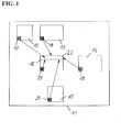
- FIG. 1 schematically shows a structure of the electronic module 11 for the level sensor 10 according to an embodiment of the invention.
- This electronic module 11 comprises a microwave assembly 12, a frequency control module 13, a power supply module 14 for powering the electronic module 11 and the level sensor 10, an interface module 15 and a detector assembly 16.
- the individual modules 12-16 each have a memory 17-21.
- non-volatile memories are used which are electrically programmable and which retain the stored data independently of a power supply.
- serial EEPROMs having a one-wire interface are used. In addition to grounding, these EEPROMs require only a single data line from which they can draw their energy.
- the detector assembly 16 has a microprocessor 22 which is electrically connectable to the individual memories 17-21.
- the electronics assemblies 12 to 15 may additionally include custom microprocessors.
- the individual modules 12 - 16 are installed in identical form in several devices, according to a modular principle.
- the assemblies go through corresponding manufacturing and test steps.
- production-relevant data such as an identification code, in particular a serial number, in the respective memory 17 - 21 of the modules 12 - 16 stored.
- the identification code can provide an indication of the type of assembly and, on the other hand, ensure a clear manufacturer assignment.
- tests such as an automatic optical inspection test (AOI), a test to ensure the explosion protection guidelines (IC test) or functional tests, in particular with regard to fault diagnosis and / or measured value or production deviations, are conceivable as test steps.
- AOI automatic optical inspection test
- IC test explosion protection guidelines
- functional tests in particular with regard to fault diagnosis and / or measured value or production deviations
- test steps With regard to the measured value or production deviations, the deviations from the desired nominal output values of the assemblies are understood for a specific input value or for a specific measured variable. After or during a successful execution of these test steps, this is stored in the respective memory 17-21 of the assemblies 12-16, likewise accumulated, relevant test data are stored. This storage can be done by the already connected for this purpose with the assembly tester.
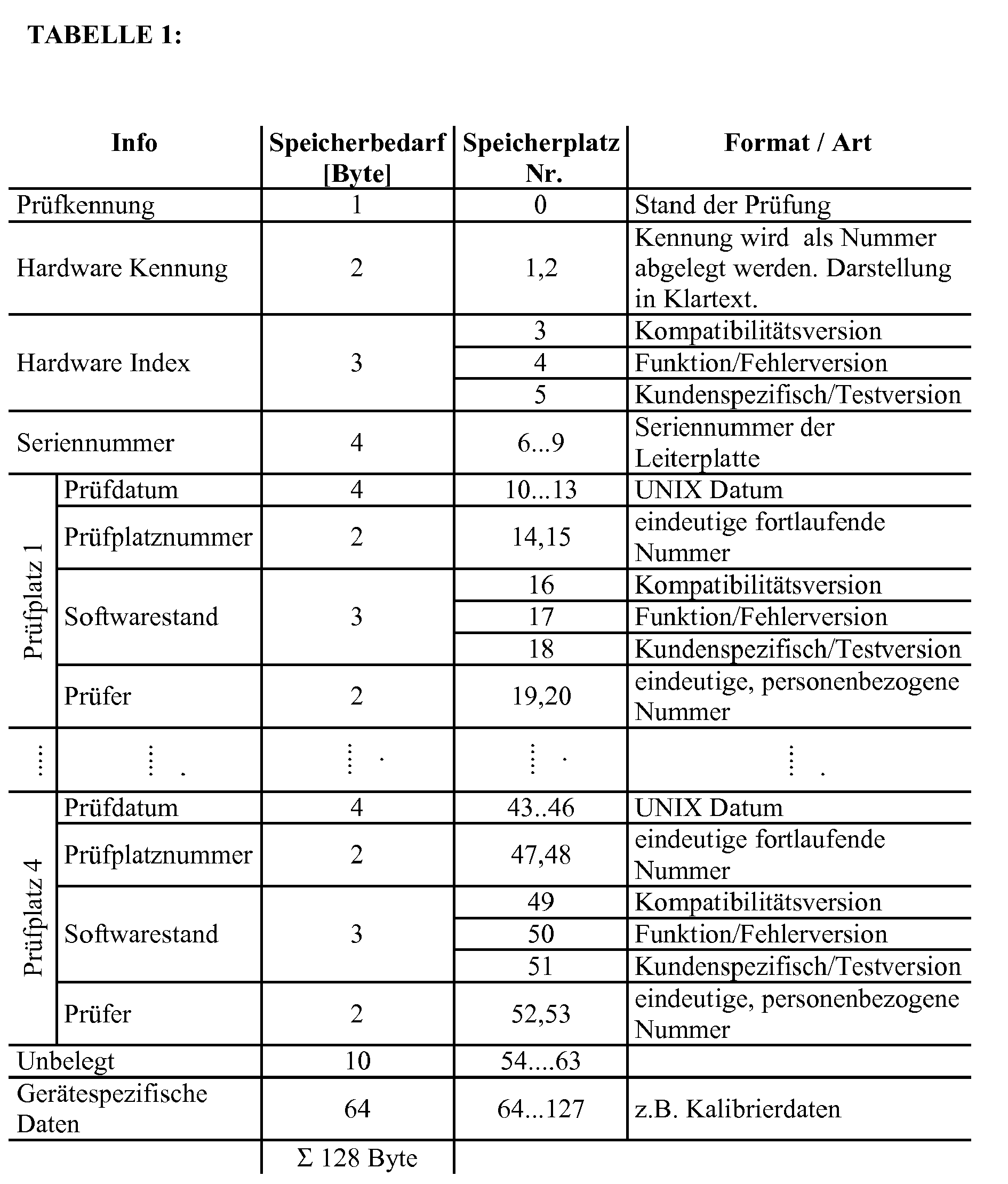
- Table 1 An example of a possible data content that can be stored in the memories 12-16 is given in Table 1.
- the memory device used in this example has a memory capacity of 128 bytes and goes through four test steps.
- Table 1 is self-explanatory in itself.
- the individual assemblies 12-16 are connected to an electronic module 11 by means of electrical Plug connections or assembled by means of no longer detachable, electrically conductive connection means (eg solder connection).
- the microprocessor 22 After assembling the assemblies 12-16 to the electronics module 11, the microprocessor 22 is electrically connected to the memories 17-21. In a subsequent commissioning of the assembly of the electronic module 11, the individual memories 17-21 are read out by the microprocessor 22.
- the microprocessor 22 can carry out a configuration, a verification and / or a calibration of the individual assemblies, of the electronic module and thus of the sensor.
- the microprocessor 22 can verify the correct composition according to the specifications of the manufacturing order.
- the assembly 12 - 16 can be identified on the basis of production data (eg an identification code or a serial number) or based on test data determined by functional testing of the assemblies, by the data content of the respective memory 17 - 21 with the due to the production order or due to the series of the microprocessor is compared by the microprocessor expected data content.
- the microprocessor 22, the electronic module 11 and thus the level sensor 10 to configure independently.
- different frequencies of the antenna 23 (different radar, microwave or ultrasonic frequencies) or the microwave assembly 12 require different settings of an analog-to-digital converter in the signal processing of the detector assembly 16, wherein the settings of the individual modules 12 - 16 independently coordinated by the microprocessor 22 made can be.
- test data from the respective memories 17-21 is evaluated as to whether all tests have passed successfully and that no assemblies are being delivered that have not passed all tests successfully. For this purpose, the status of the tests is evaluated by means of the read-out memory contents.
- test data such as adjustment values that are individually based on the module
- the calibration data of a D / A converter drive for generating the current output level of the power supply unit 14 is detected in the functional test of the power supply unit 14 and stored as test data in the memory 19 of the power supply unit 14.
- These acquired calibration data may then be used by the microprocessor 22 after assembly of the electronic module to drive the power supply assembly 14 so that the level sensor has the required current output level. Until now this required a manual calibration of the current output at the final balancing position of the level sensors.
- the memory contents of the memories 17-21 comprise an identification code or a unique serial number, the serial number range of each delivery being communicated to the customer during distribution of the components. This serial number can be read in the complete device and thus serve as proof that the electronic module really comes from a specific manufacturer.
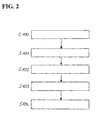
- FIG. 2 shows the inventive method for producing a sensor.
- module-specific data of a plurality of electronic assemblies 12-16 are determined in step S100.
- step S101 the module-specific data in respective memory 17 - 21 of the modules 12 - 16 stored.
- step S102 the modules 12-16 are assembled in an electronic module 11 in step S102, wherein an electronic coupling of the assemblies 12-16 takes place with a processor 22.
- the data thus accessible to the processor 22 are read out in step S103 and evaluated in a subsequent step S104.
Abstract
Description
Die Erfindung betrifft einen Sensor, insbesondere einen Füllstandsensor, und ein Verfahren zur Herstellung eines Sensors.The invention relates to a sensor, in particular a fill level sensor, and a method for producing a sensor.
Sensoren im Sinne dieser Anmeldung können jede Art von Messgeräten sein, beispielsweise Füllstandsensoren, Drucksensoren, Grenzstandsensoren oder Temperatursensoren, um nur einige Beispiele zu nennen. Zur Erfassung können dabei unterschiedliche physikalische Effekte ausgenutzt werden. Die Messwerterfassung kann mit Hilfe von Radarwellen, Ultraschall, Vibration, geführter Mikrowelle (TDR, Time Domain Reflexion) oder kapazitiver Effekte erfolgen.Sensors in the sense of this application can be any type of measuring device, for example level sensors, pressure sensors, point level sensors or temperature sensors, to name just a few examples. To capture different physical effects can be exploited. The data acquisition can be done with the help of radar waves, ultrasound, vibration, guided microwave (TDR, Time Domain Reflexion) or capacitive effects.
Bekannte Füllstandsensoren für eine berührungslose Messung weisen eine Antenne auf, welche Signale unter Ausnutzung der genannten Effekte sendet bzw. empfängt, um den Füllstand eines Mediums, z.B. in einem Füllgutbehälter, zu ermitteln. Die Antenne eines solchen Füllstandsensors ist dabei beispielsweise innerhalb des Behälters oberhalb des Mediums angeordnet.Known fill level sensors for non-contact measurement have an antenna which sends or receives signals by utilizing the mentioned effects in order to determine the fill level of a medium, eg in a product container. The antenna of such a level sensor is arranged, for example, within the container above the medium.
Elektronikmodule solcher Sensoren bestehen im Allgemeinen aus mehreren elektronischen Baugruppen. Diese Baugruppen werden oftmals in identischer Form in verschiedene Sensoren verbaut, so dass sich je nach Zusammenstellung der Baugruppen unterschiedliche Sensoren oder Sensoren mit unterschiedlichen Eigenschaften ergeben. Die elektronischen Baugruppen durchlaufen separat die notwendigen Fertigungs- und Prüfschritte und werden erst bei der Komplettierung des Elektronikmoduls zusammengebaut. Eine Identifizierung der verschiedenen elektronischen Baugruppen ist dabei nur optisch möglich, so dass die Gefahr besteht, dass die falschen Baugruppen zu einem Elektronikmodul zusammengebaut werden. Eine derartige falsche Zusammensetzung kann bisher nur anhand abschließender Funktionstests der Elektronikmodule festgestellt werden, was zeitaufwendig ist und zusätzliche Arbeitsschritte erforderlich macht. Darüber hinaus ist ferner die Möglichkeit denkbar, dass eine elektronische Baugruppe verbaut wird, die nicht sämtliche Prüfschritte durchlaufen hat. Ferner kann das Verbauen baugleicher Baugruppen in verschiedene Sensoren eine Anpassung und Abstimmung erforderlich machen, was wiederum einen zusätzlichen Arbeitsschritt erfordert und einen höheren Herstellungsaufwand mit sich bringt.Electronic modules of such sensors generally consist of several electronic assemblies. These modules are often installed in identical form in different sensors, so that arise depending on the composition of the modules different sensors or sensors with different properties. The electronic assemblies go through the necessary manufacturing and test steps separately and are assembled at the completion of the electronic module. An identification of the various electronic modules is only optically possible, so that there is a risk that the wrong modules are assembled to form an electronic module. Such a false composition can be found only on the basis of final functional tests of the electronic modules, which is time-consuming and requires additional steps required. In addition, the possibility is also conceivable that an electronic module is installed, which has not gone through all the test steps. Furthermore, obstructing identical components in different sensors can necessitate adaptation and tuning, which in turn requires an additional work step and entails a higher manufacturing outlay.
Der Erfindung liegt die Aufgabe zugrunde, die geschilderten Probleme des Standes der Technik zu verbessern und insbesondere die Zusammenstellung einzelner elektronischer Baugruppen in einem Sensor sicherzustellen und zu vereinfachen.The invention has for its object to improve the described problems of the prior art and in particular to ensure the assembly of individual electronic assemblies in a sensor and simplify.
Diese Aufgabe wird mit einem Sensor und einem Verfahren zur Herstellung eines Sensors gemäß der unabhängigen Ansprüche gelöst.This object is achieved with a sensor and a method for producing a sensor according to the independent claims.
Vorteilhafte Weiterentwicklungen der Erfindung sind Gegenstand der abhängigen Ansprüche.Advantageous developments of the invention are the subject of the dependent claims.
Die beschriebenen Ausführungsbeispiele betreffen gleichermaßen den Sensor und das Verfahren zur Herstellung des Sensors, so dass sich die im Hinblick auf den Sensor beschriebenen Ausführungsbeispiele auch im Verfahren implementieren lassen und umgekehrt. Außerdem lassen sich die im Zusammenhang mit dem Sensor beschriebenen Vorteile gleichermaßen mit dem Verfahren zum Herstellen des Sensors erzielen.The described embodiments equally relate to the sensor and the method for producing the sensor, so that the embodiments described with regard to the sensor can also be implemented in the method and vice versa. In addition, the advantages described in connection with the sensor can be achieved equally with the method for producing the sensor.
Die Erfindung baut auf dem gattungsgemäßen Stand der Technik auf, durch einen Sensor mit einem Elektronikmodul, welches mehrere elektronische Baugruppen umfasst und einem Prozessor, der mit den elektronischen Baugruppen elektrisch koppelbar ist, wobei die Baugruppen jeweils einen programmierbaren Speicher mit baugruppenspezifischen Daten der jeweiligen Baugruppe aufweisen, deren Speicherinhalt von dem Prozessor ausles- und auswertbar ist. Dies bringt den Vorteil mit sich, dass die Speicher der Baugruppen nach oder während der Fertigung und/oder nach oder während der anschließenden Funktionsprüfung der Baugruppen mit Daten programmiert werden können, welche die individuelle Baugruppe betreffen. Dadurch können dem Prozessor spezifische die einzelne Baugruppe betreffende Informationen mitgeteilt werden, welche dieser wiederum für einen verbesserten Betrieb und eine verbesserte Abstimmung des Informationsaustausches und des Zusammenwirkens zwischen ihm selbst und der entsprechenden Baugruppe sowie zwischen den Baugruppen untereinander verwenden kann. Die beispielsweise durch eine Funktionsprüfung der Baugruppe gewonnenen Ergebnisse werden somit nicht wieder verworfen, sondern können als Basis für die Abstimmung des Betriebs des Elektronikmoduls bzw. des Sensors dienen. Dies eröffnet eine Vielzahl von Möglichkeiten und damit verbundenen Vorteilen. Beispielsweise kann dadurch nach dem Zusammenbau der Baugruppen durch den Prozessor überprüft werden, ob die Zusammenstellung korrekt, d.h. mit den richtigen Baugruppen, erfolgt ist. Ferner kann dadurch durch den Prozessor eine Konfiguration des Elektronikmoduls in Abhängigkeit der Zusammenstellung oder eine Kalibrierung in Abhängigkeit der Prüfergebnisse erfolgen. Darüber hinaus kann der Prozessor nach der Zusammenstellung überprüfen, ob die jeweilige Baugruppe alle Tests erfolgreich durchlaufen hat, um sicherzustellen, dass nur Baugruppen in den Vertrieb gelangen, die vollumfänglich geprüft wurden.The invention is based on the generic state of the art, by a sensor with an electronic module, which comprises a plurality of electronic modules and a processor which is electrically coupled to the electronic modules, wherein the modules each have a programmable memory with module-specific data of the respective module whose memory contents can be read and evaluated by the processor. This has the advantage that the memory of the modules can be programmed after or during the production and / or after or during the subsequent functional testing of the modules with data relating to the individual module. Thereby, the processor can be informed of specific information concerning the individual module, which in turn can use this for improved operation and an improved coordination of the information exchange and the interaction between itself and the corresponding module as well as between the modules. The results, for example, obtained by a functional test of the assembly are thus not discarded again, but can serve as a basis for tuning the operation of the electronic module or the sensor. This opens up a multitude of possibilities and associated advantages. For example, it can be checked by the processor after assembly of the modules, if the compilation is done correctly, ie with the correct modules. Furthermore, by the processor, a configuration of the electronic module in Dependent composition or calibration depending on the test results done. In addition, after assembly, the processor can verify that each assembly has successfully completed all tests to ensure that only assemblies that have been fully tested are distributed.
Ferner kann vorteilhafterweise vorgesehen sein, dass die Speicher nicht-flüchtige Speicher, insbesondere serielle EEPROMs mit einer Ein-Draht-Schnittstelle, sind. Durch die Verwendung nicht-flüchtiger Speicher bleibt der Dateninhalt nach der Fertigung und Prüfung der Baugruppen dauerhaft in den Speichern dieser Baugruppen erhalten - auch nach Ausbau einer Baugruppe und Verwendung dieser Baugruppe in einem anderen Elektronikmodul. Vorteilhafterweise kommen hierfür die genannten EEPROMs zum Einsatz, die den Vorteil bieten, dass diese keinen separaten Spannungsanschluss erfordern, sondern ihre Energie über die Datenleitung beziehen. Dadurch können entsprechende Zuleitungen eingespart werden.Furthermore, it can advantageously be provided that the memories are non-volatile memories, in particular serial EEPROMs with a one-wire interface. By using non-volatile memory, the data content remains permanently in the memories of these modules after production and testing of the modules - even after removing one module and using this module in another electronic module. Advantageously, the said EEPROMs are used for this purpose, which offer the advantage that they do not require a separate voltage connection, but instead obtain their energy via the data line. As a result, corresponding supply lines can be saved.
Außerdem kann die Erfindung dadurch weitergebildet sein, dass die Daten einen Identifikationscode zur Bestimmung der Baugruppe und/oder des Herstellers umfassen. Dieser Identifikationscode ermöglicht neben der automatischen Überprüfung der Richtigkeit der Zusammenstellung durch den Prozessor und der Selbstkonfiguration des Elektronikmoduls auch eine Abfrage des Herstellers durch den Prozessor. Somit kann der Identifikationscode auch als eindeutiges Erkennungsmerkmal dienen mit dem ein Schutz vor Nachbau und Kopieren realisiert werden kann, da der Prozessor nicht von einem bestimmten Hersteller gefertigte Baugruppen nicht akzeptiert oder an den Benutzer oder Hersteller (z.B. im Rahmen von Reparaturarbeiten) meldet.In addition, the invention can be further developed in that the data comprise an identification code for determining the assembly and / or the manufacturer. This identification code, in addition to the automatic verification of the accuracy of the compilation by the processor and the self-configuration of the electronic module also allows a query of the manufacturer by the processor. Thus, the identification code can also serve as a unique identifier with which protection against copying and copying can be realized since the processor does not accept or report to non-manufacturer-manufactured assemblies (e.g., in the course of repair work).
Insbesondere ist dabei vorgesehen, dass der Identifikationscode eine Seriennummer ist. Eine solche individuelle Seriennummer wird vom Hersteller der Baugruppe nur einmal vergeben und ist dieser eindeutig zugeordnet. Beim Bezug solcher Bauteile kann der Seriennummernbereich dem Kunden mitgeteilt werden. Diese Bauteilseriennummer kann in die Überwachung bei der Konfiguration des Elektronikmoduls und beim späteren Betrieb des Sensors einbezogen werden. Genauer bedeutet dies, dass der Sensor beim Einschalten diese Seriennummer kontrollieren wird. Liegt sie nicht im von der Software erwarteten Bereich bzw. hat sie nicht den von der Software erwarteten Wert, dann wird der Sensor keinen ordnungsgemäßen Betrieb aufnehmen. Dadurch lassen sich die eben genannten Vorteile bezüglich Selbstkonfiguration des Elektronikmoduls, Überprüfung der Zusammenstellung und Kopierschutz noch besser realisieren.In particular, it is provided that the identification code is a serial number. Such an individual serial number is only provided by the manufacturer of the module once awarded and this is clearly assigned. When purchasing such components, the serial number range can be communicated to the customer. This part serial number can be included in the monitoring during the configuration of the electronic module and in the later operation of the sensor. Specifically, this means that the sensor will control this serial number at power-up. If it is not within the software expected range or does not have the software expected value, the sensor will not operate properly. As a result, the aforementioned advantages with respect to self-configuration of the electronic module, checking the composition and copy protection can be realized even better.
Eine weitere Ausführungsform kann dadurch realisiert werden, dass die Daten durch Funktionsprüfung der Baugruppe ermittelte Prüfdaten umfassen. Dies bringt den Vorteil mit sich, dass eine Kalibrierung abhängig von Prüfergebnissen ermöglicht wird. Dies hat den Vorteil, dass die Anpassung der Baugruppe an die anderen Baugruppen bzw. das Elektronikmodul nicht nur auf die Art der jeweiligen Baugruppe, sondern auf die individuelle Baugruppe abgestimmt werden kann, so dass sogar Aspekte wie beispielsweise Fertigungstoleranzen und Fehlerkorrektur möglich sind. Erfindungsgemäß ist somit nunmehr möglich, Test- bzw. Prüfergebnisse und damit verbundene Abgleichwerte der einzelnen Baugruppen in das fertiggestellte Elektronikmodul zu übernehmen, so dass die Abstimmung der einzelnen Baugruppen automatisch durch den Prozessor erfolgen kann und eine manuelle Abstimmung in einem weiteren Arbeitsschritt entfallen kann.A further embodiment can be realized in that the data comprise test data determined by functional testing of the module. This has the advantage of allowing calibration depending on test results. This has the advantage that the adaptation of the module to the other modules or the electronic module can be adapted not only to the type of the respective module, but to the individual module, so that even aspects such as manufacturing tolerances and error correction are possible. According to the invention, it is thus now possible to take over test and / or test results and associated adjustment values of the individual modules in the finished electronic module, so that the tuning of the individual modules can be done automatically by the processor and manual tuning in a further step can be dispensed with.
In diesem Zusammenhang ist dabei besonders vorteilhaft, dass die Prüfdaten durch Prüfung ermittelte Messwerte oder Fertigungsabweichungen der Baugruppen umfassen.In this context, it is particularly advantageous that the test data comprise measured values determined by testing or manufacturing deviations of the assemblies.
Vorteilhafterweise ist bei der Erfindung vorgesehen, dass die Daten mit vom Prozessor erwarteten Daten verifizierbar sind, um die Richtigkeit einer Zusammenstellung der Baugruppen zu überprüfen. Dies hat den Vorteil, dass falsche Zusammenstellungen der Baugruppen seitens des Prozessors überprüft und automatisch erkannt werden können. Dazu überprüft der Prozessor, ob die tatsächliche Baugruppenzusammenstellung einer für den gewünschten Sensor vorgesehenen Zusammenstellung entspricht. Als Daten zur Identifikation der Baugruppe kommen beispielsweise ein Identifikationscode oder eine Seriennummer in Frage. Mit diesen Daten unterzieht sich das Elektronikmodul nach der Zusammenstellung selbständig einer Verifizierung der Richtigkeit der Zusammenstellung, so dass ein abschließender dahingehender Funktionstest entfallen kann.Advantageously, it is provided in the invention that the data with verifiable by the processor data are verifiable to verify the accuracy of a compilation of the modules. This has the advantage that incorrect compilations of the modules can be checked by the processor and automatically detected. For this purpose, the processor checks whether the actual module assembly corresponds to a composition intended for the desired sensor. As identification data for the assembly, for example, an identification code or a serial number in question. With these data, the electronic module undergoes independent verification of the correctness of the compilation after the compilation, so that a final pertinent functional test can be omitted.
Ferner kann vorteilhafterweise vorgesehen sein, dass der Betrieb des Elektronikmoduls in Abhängigkeit der Daten konfigurierbar ist. Dabei erkennt der Prozessor beispielsweise anhand des Identifikationscodes oder der Seriennummer, um welche Baugruppe es sich handelt und nimmt anhand dieser Erkenntnis entsprechende Einstellungen des Elektronikmoduls vor. Der Prozessor konfiguriert die Abstimmung der einzelnen Baugruppen untereinander und konfiguriert das Zusammenwirken zwischen ihm und der jeweiligen Baugruppe. Bei der Konfiguration erfolgt mittels der oben genannten Möglichkeiten eine Identifikation der Art der Baugruppe und seitens des Prozessors eine Auswahl der Kommunikationsweise zwischen Prozessor und der entsprechenden Baugruppe sowie eventuell der Baugruppen untereinander. Außerdem kann der Prozessor anhand der Identifikation der Baugruppe gegebenenfalls eine Einstellung dieser oder der anderen Baugruppen vornehmen. Das heißt es steht eine Auswahl an verschiedenen Kommunikationsweisen und Einstellungen zur Verfügung aus der abhängig von der Identifikation der Baugruppe vom Prozessor ausgewählt wird.Furthermore, it can advantageously be provided that the operation of the electronic module can be configured as a function of the data. In this case, the processor recognizes, for example on the basis of the identification code or the serial number, to which module is concerned and takes on the basis of this knowledge corresponding settings of the electronic module. The processor configures the alignment of the individual modules with each other and configures the interaction between it and the respective module. In the configuration, by means of the abovementioned possibilities, an identification of the type of the assembly and on the part of the processor a selection of the communication method between the processor and the corresponding assembly as well as possibly of the assemblies with each other. In addition, the processor can optionally make an adjustment of this or the other modules based on the identification of the module. That is, there is a selection of different communication modes and settings available from which the processor is selected depending on the identification of the module.
Eine weitere vorteilhafte Weiterentwicklung der Erfindung besteht darin, dass der Betrieb des Elektronikmoduls in Abhängigkeit der Daten kalibrierbar ist. Hierbei sind die Daten vorzugsweise Fertigungs- bzw. Prüfdaten. Im Unterschied zur Konfiguration erfolgt nicht lediglich die Zuordnung zu einer vorgegebenen zahlenmäßig begrenzten Kommunikationsweise oder einem Einstellungssatz, sondern es erfolgt eine völlig individuelle Anpassung an die abgespeicherten Prüfergebnisse der Baugruppe. Dies beinhaltet Aspekte wie beispielsweise den Ausgleich von Fertigungstoleranzen oder eine Fehlerkorrektur, was die Funktionsgenauigkeit des fertiggestellten Elektronikmoduls erhöht. Wie oben bereits erwähnt, ist somit nunmehr möglich, Test- bzw. Prüfergebnisse und damit verbundene Abgleichwerte der einzelnen Baugruppen in das fertiggestellte Elektronikmodul zu übernehmen, so dass die Abstimmung der einzelnen Baugruppen automatisch durch den Prozessor erfolgen und eine manuelle Abstimmung in einem weiteren Arbeitsschritt entfallen kann.A further advantageous development of the invention consists in that the operation of the electronic module can be calibrated as a function of the data. In this case, the data are preferably production or test data. In contrast to the configuration, not only does the assignment to a given numerically limited communication mode or setting set occur, but there is a completely individual adaptation to the stored test results of the module. This includes aspects such as the compensation of manufacturing tolerances or an error correction, which increases the functional accuracy of the finished electronic module. As already mentioned above, it is thus now possible to take over test and / or test results and associated adjustment values of the individual assemblies in the finished electronic module, so that the tuning of the individual assemblies is done automatically by the processor and eliminates manual tuning in a further step can.
Im Folgenden wird mit Verweis auf die Figuren ein Ausführungsbeispiel der Erfindung beschrieben.In the following, an embodiment of the invention will be described with reference to the figures.
- Fig. 1Fig. 1
- zeigt schematisch einen Aufbau eines Elektronikmoduls für einen Füllstandsensor gemäß einem Ausführungsbeispiel der Erfindung;schematically shows a structure of an electronic module for a level sensor according to an embodiment of the invention;
- Fig. 2Fig. 2
- zeigt das erfindungsgemäße Verfahren zur Herstellung eines Sensors, undshows the inventive method for producing a sensor, and
- Fig. 3Fig. 3
- zeigt den Füllstandsensor gemäß dem erfindungsgemäßen Ausführungsbeispiel.shows the level sensor according to the embodiment of the invention.
Ferner weist die Detektorbaugruppe 16 einen Mikroprozessor 22 auf, der mit den einzelnen Speichern 17 - 21 elektrisch verbindbar ist. Außerdem können die Elektronikbaugruppen 12 bis 15 zusätzlich noch für spezielle Aufgaben zugeschnittene Mikroprozessoren beinhalten.Furthermore, the
Die einzelnen Baugruppen 12 - 16 werden in identischer Form in mehrere Geräte, entsprechend einem Baukastenprinzip, verbaut. Dabei durchlaufen die Baugruppen entsprechende Fertigungs- und Prüfschritte. Nach dem Durchlaufen der Fertigungsschritte werden fertigungsrelevante Daten wie beispielsweise ein Identifikationscode, insbesondere eine Seriennummer, in dem jeweiligen Speicher 17 - 21 der Baugruppen 12 - 16 abgespeichert. Der Identifikationscode kann einerseits einen Rückschluss auf die Art der Baugruppe geben und andererseits eine eindeutige Herstellerzuordnung sicherstellen.The individual modules 12 - 16 are installed in identical form in several devices, according to a modular principle. The assemblies go through corresponding manufacturing and test steps. After passing through the production steps, production-relevant data such as an identification code, in particular a serial number, in the respective memory 17 - 21 of the modules 12 - 16 stored. On the one hand, the identification code can provide an indication of the type of assembly and, on the other hand, ensure a clear manufacturer assignment.
Als Prüfschritte sind in diesem Zusammenhang Tests wie ein Automatisch Optischer Inspektionstest (AOI), ein Test zur Sicherstellung der Explosionsschutzrichtlinien (IC-Test) oder Funktionstests, insbesondere hinsichtlich Fehlerdiagnose und/oder Messwert- bzw. Fertigungsabweichungen, denkbar. Hinsichtlich der Messwert- bzw. Fertigungsabweichungen werden die Abweichungen von gewünschten Sollausgabewerten der Baugruppen bei einem bestimmten Eingangswert oder bei einer bestimmten Messgröße verstanden. Nach oder während einem erfolgreichen Durchlaufen dieser Prüfschritte wird dies im jeweiligen Speicher 17 - 21 der Baugruppen 12 - 16 hinterlegt, ebenso werden angefallene, relevante Prüfdaten abgespeichert. Dieses Speichern kann durch das ohnehin für diese Zwecke mit der Baugruppe verbundene Prüfgerät erfolgen.In this context, tests such as an automatic optical inspection test (AOI), a test to ensure the explosion protection guidelines (IC test) or functional tests, in particular with regard to fault diagnosis and / or measured value or production deviations, are conceivable as test steps. With regard to the measured value or production deviations, the deviations from the desired nominal output values of the assemblies are understood for a specific input value or for a specific measured variable. After or during a successful execution of these test steps, this is stored in the respective memory 17-21 of the assemblies 12-16, likewise accumulated, relevant test data are stored. This storage can be done by the already connected for this purpose with the assembly tester.
Ein Beispiel für einen möglichen Dateninhalt, wie er in den Speichern 12 - 16 abgelegt werden kann, ist in Tabelle 1 gegeben. Der in diesem Beispiel verwendete Speicherbaustein hat eine Speicherkapazität von 128 Byte und durchläuft vier Prüfschritte. Im Übrigen ist die Tabelle 1 von sich aus selbsterklärend.
Nach dem Durchlaufen sämtlicher Fertigungs- und Prüfschritte werden die einzelnen Baugruppen 12 - 16 zu einem Elektronikmodul 11 mittels elektrischer Steckverbindungen oder mittels nicht mehr lösbarer, elektrisch leitender Verbindungsmittel (z.B. Lötverbindung) zusammengebaut.After passing through all manufacturing and testing steps, the individual assemblies 12-16 are connected to an
Nach dem Zusammenbau der Baugruppen 12 - 16 zu dem Elektronikmodul 11 ist der Mikroprozessor 22 mit den Speichern 17 - 21 elektrisch verbunden. Bei einer dem Zusammenbau des Elektronikmoduls 11 folgenden Erstinbetriebnahme werden die einzelnen Speicher 17 - 21 vom Mikroprozessor 22 ausgelesen.After assembling the assemblies 12-16 to the
Anhand dieser ausgelesenen Daten kann der Mikroprozessor 22 eine Konfiguration, eine Verifikation und/oder eine Kalibrierung der einzelnen Baugruppen, des Elektronikmoduls und somit des Sensors durchführen.On the basis of this read-out data, the
Bei der Konfiguration kann der Mikroprozessor 22 die korrekte Zusammenstellung nach den Vorgaben des Fertigungsauftrages überprüfen. Dazu kann die Baugruppe 12 - 16 anhand von Fertigungsdaten (z.B. einem Identifikationscode oder einer Seriennummer) oder anhand von durch Funktionsprüfung der Baugruppen ermittelten Prüfdaten erkannt werden, indem der Dateninhalt des jeweiligen Speichers 17 - 21 mit dem aufgrund des Fertigungsauftrages oder aufgrund der Baureihe des Mikroprozessors vom Mikroprozessor erwarteten Dateninhalt verglichen wird. Darüber hinaus kann der Mikroprozessor 22 das Elektronikmodul 11 und somit auch den Füllstandsensor 10 selbständig konfigurieren. Beispielsweise benötigen unterschiedliche Frequenzen der Antenne 23 (unterschiedliche Radar-, Mikrowellen- oder Ultraschallfrequenzen) oder der Mikrowellenbaugruppe 12 unterschiedliche Einstellungen eines Analog-Digitalwandlers bei der Signalverarbeitung der Detektorbaugruppe 16, wobei die Einstellungen der einzelnen Baugruppen 12 - 16 eigenständig koordiniert durch den Mikroprozessor 22 vorgenommen werden können.In the configuration, the
Bei der Verifikation werden die Prüfdaten aus den jeweiligen Speichern 17 - 21 dahingehend ausgewertet, ob alle Tests erfolgreich durchlaufen wurden und dass keine Baugruppen zur Auslieferung kommen, die nicht alle Tests erfolgreich durchlaufen haben. Dazu wird mittels des ausgelesenen Speicherinhalts der Stand der Prüfungen bewertet.During verification, the test data from the respective memories 17-21 is evaluated as to whether all tests have passed successfully and that no assemblies are being delivered that have not passed all tests successfully. For this purpose, the status of the tests is evaluated by means of the read-out memory contents.
Bei der Kalibrierung werden Prüfdaten, wie beispielsweise Abgleichwerte, die individuell baugruppenbezogen sind, für den Betrieb des Elektronikmoduls 11 übernommen. So werden beispielsweise die Kalibrierdaten einer D/A-Wandleransteuerung zur Generierung des Stromausgangspegels der Netzteilbaugruppe 14 in der Funktionsprüfung der Netzteilbaugruppe 14 erfasst und als Prüfdaten im Speicher 19 der Netzteilbaugruppe 14 hinterlegt. Diese erfassten Kalibrierdaten können dann vom Mikroprozessor 22 nach dem Zusammenbau des Elektronikmoduls zur Ansteuerung der Netzteilbaugruppe 14 verwendet werden, so dass der Füllstandsensor den geforderten Stromausgangspegel aufweist. Bisher erforderte dies eine manuelle Kalibrierung des Stromausgangs am Endabgleichplatz der Füllstandsensoren.During calibration, test data, such as adjustment values that are individually based on the module, are adopted for the operation of the
Eine weitere Funktion, die sich durch die Hinterlegung der Fertigungs- und/oder Prüfdaten realisieren lässt ist ein Kopierschutz bzw. Herstellernachweis. Dabei umfasst der Speicherinhalt der Speicher 17 - 21 einen Identifikationscode oder eine eindeutige Seriennummer, wobei beim Vertrieb der Bauteile dem Abnehmer der Seriennummernbereich jeder Lieferung mitgeteilt wird. Diese Seriennummer kann im Komplettgerät ausgelesen werden und somit als Nachweis dienen, dass das Elektronikmodul wirklich von einem bestimmten Hersteller stammt.Another function, which can be realized by depositing the production and / or test data is a copy protection or manufacturer proof. In this case, the memory contents of the memories 17-21 comprise an identification code or a unique serial number, the serial number range of each delivery being communicated to the customer during distribution of the components. This serial number can be read in the complete device and thus serve as proof that the electronic module really comes from a specific manufacturer.
Ergänzend wird darauf hingewiesen, dass "umfassend" und "aufweisend" keine anderen Elemente oder Schritte ausschließt und "eine" oder "ein" keine Vielzahl ausschließt. Ferner sei darauf hingewiesen, dass Merkmale oder Schritte, die mit Verweis auf eine der obigen Weiterentwicklungen beschrieben worden sind, auch in Kombination mit anderen Merkmalen oder Schritten anderer oben beschriebener Weiterentwicklungen verwendet werden können. Bezugszeichen in den Ansprüchen sind nicht als Einschränkung anzusehen.In addition, it should be noted that "comprising" and "having" does not exclude other elements or steps, and "a" or "an" does not exclude a plurality. It should also be appreciated that features or steps described with reference to any of the above developments may also be used in combination with other features or steps of other developments described above. Reference signs in the claims are not to be considered as limiting.
Claims (15)
die Speicher (17 - 21) nicht-flüchtige Speicher, insbesondere serielle EEPROMs mit einer Ein-Draht-Schnittstelle, sind.A sensor (10) according to claim 1, wherein
the memories (17-21) are non-volatile memories, in particular serial EEPROMs with a one-wire interface.
die Daten einen Identifikationscode zur Bestimmung der Baugruppe (12 - 16) und/oder des Herstellers umfassen.Sensor (10) according to one of the preceding claims, wherein
the data comprises an identification code for determining the assembly (12-16) and / or the manufacturer.
der Identifikationscode eine Seriennummer ist.A sensor (10) according to claim 3, wherein
the identification code is a serial number.
die Daten durch Funktionsprüfung der Baugruppe (12 - 16) ermittelte Prüfdaten umfassen.Sensor (10) according to one of the preceding claims, wherein
the data comprise test data determined by function test of the module (12 - 16).
die Prüfdaten durch Prüfung ermittelte Messwerte der Baugruppe (12 - 16) umfassen.A sensor (10) according to claim 5, wherein
the test data comprise measured values of the module (12-16) determined by testing.
die Prüfdaten durch Prüfung ermittelte Fertigungsabweichungen der Baugruppe (12 - 16) umfassen.A sensor (10) according to claim 5, wherein
the test data comprise inspection deviations of the assembly (12 - 16) determined by testing.
die Daten mit vom Prozessor (22) erwarteten Daten verifizierbar sind, um die Richtigkeit einer Zusammenstellung der Baugruppen (12 - 16) zu überprüfen.Sensor (10) according to one of the preceding claims, wherein
the data is verifiable with data expected from the processor (22) to verify the correctness of an assembly of the assemblies (12-16).
der Betrieb des Elektronikmoduls (11) in Abhängigkeit der Daten konfigurierbar ist.Sensor (10) according to one of the preceding claims, wherein
the operation of the electronic module (11) is configurable as a function of the data.
der Betrieb des Elektronikmoduls (11) in Abhängigkeit der Daten kalibrierbar ist.Sensor (10) according to one of the preceding claims, wherein
the operation of the electronic module (11) can be calibrated as a function of the data.
die Daten Informationen über die Art von an der Baugruppe (12 - 16) durchgeführten Funktionsprüfungen umfassen, und
die Daten mit vom Prozessor (22) erwarteten Daten verifizierbar sind, um die Vollständigkeit der Funktionsprüfungen der Baugruppen (12 - 16) zu überprüfen.Sensor (10) according to one of the preceding claims, wherein
the data include information about the type of functional tests performed on the assembly (12-16), and
the data is verifiable with data expected by the processor (22) to verify the integrity of the functional tests of the assemblies (12-16).
für die Baugruppen (12 - 16) ein oder mehrere Elemente der Gruppe bestehend aus: einer Mikrowellenbaugruppe (12), einer Schnittstellenbaugruppe (15), einer Netzteilbaugruppe (14), einer Detektorbaugruppe (16) und einer Frequenzsteuerungsbaugruppe (13) vorgesehen sind.Sensor (10) according to one of the preceding claims, wherein
for the assemblies (12-16), one or more of the group consisting of: a microwave assembly (12), an interface assembly (15), a power supply assembly (14), a detector assembly (16), and a frequency control assembly (13).
der Sensor (10) ein Füllstandsensor ist.A sensor (10) according to any one of claims 1 to 12, wherein
the sensor (10) is a level sensor.
Priority Applications (3)
| Application Number | Priority Date | Filing Date | Title |
|---|---|---|---|
| EP08168401.1A EP2184591B1 (en) | 2008-11-05 | 2008-11-05 | Sensor comprising memory-equipped modules |
| US12/576,559 US9014998B2 (en) | 2008-11-05 | 2009-10-09 | Sensor with subassemblies featuring storage devices |
| CN200910209349.5A CN101738242B (en) | 2008-11-05 | 2009-11-04 | Sensor comprising memory-equipped modules |
Applications Claiming Priority (1)
| Application Number | Priority Date | Filing Date | Title |
|---|---|---|---|
| EP08168401.1A EP2184591B1 (en) | 2008-11-05 | 2008-11-05 | Sensor comprising memory-equipped modules |
Publications (3)
| Publication Number | Publication Date |
|---|---|
| EP2184591A1 true EP2184591A1 (en) | 2010-05-12 |
| EP2184591A9 EP2184591A9 (en) | 2010-12-08 |
| EP2184591B1 EP2184591B1 (en) | 2016-05-25 |
Family
ID=40512270
Family Applications (1)
| Application Number | Title | Priority Date | Filing Date |
|---|---|---|---|
| EP08168401.1A Not-in-force EP2184591B1 (en) | 2008-11-05 | 2008-11-05 | Sensor comprising memory-equipped modules |
Country Status (3)
| Country | Link |
|---|---|
| US (1) | US9014998B2 (en) |
| EP (1) | EP2184591B1 (en) |
| CN (1) | CN101738242B (en) |
Families Citing this family (2)
| Publication number | Priority date | Publication date | Assignee | Title |
|---|---|---|---|---|
| US9243938B2 (en) | 2010-08-04 | 2016-01-26 | Fluke Corporation | Single TEDS electronic data sheet for multiple accelerometers |
| DE102011054462A1 (en) * | 2011-10-13 | 2013-04-18 | Wika Alexander Wiegand Se & Co. Kg | Control device for use in tank management device for monitoring level of fuel in tank, has interface transmitting external data between digital-electronic conversion device and external communication partner |
Citations (7)
| Publication number | Priority date | Publication date | Assignee | Title |
|---|---|---|---|---|
| US6314023B1 (en) | 2000-06-15 | 2001-11-06 | Motorola, Inc. | Non-volatile programming elements for redundancy and identification in an integrated circuit |
| US6437692B1 (en) * | 1998-06-22 | 2002-08-20 | Statsignal Systems, Inc. | System and method for monitoring and controlling remote devices |
| US20050275527A1 (en) * | 2004-05-27 | 2005-12-15 | Lawrence Kates | Wireless repeater for sensor system |
| US20060179251A1 (en) * | 2005-02-10 | 2006-08-10 | International Business Machines Corporation | Method and apparatus to operate cache-inhibited memory mapped commands to access registers |
| US20060267756A1 (en) * | 2004-05-27 | 2006-11-30 | Lawrence Kates | System and method for high-sensitivity sensor |
| US7184924B1 (en) * | 2005-11-03 | 2007-02-27 | International Business Machines Corporation | Method, apparatus and computer program product for implementing thermal integrity screening |
| WO2007027342A1 (en) | 2005-08-31 | 2007-03-08 | Lawrence Kates | Method and apparatus for detecting severity of water leaks |
Family Cites Families (8)
| Publication number | Priority date | Publication date | Assignee | Title |
|---|---|---|---|---|
| US4862067A (en) * | 1987-06-24 | 1989-08-29 | Schlumberger Technologies, Inc. | Method and apparatus for in-circuit testing of electronic devices |
| US5586085A (en) * | 1991-10-31 | 1996-12-17 | Lichte; Leo J. | Container and adaptor for use with fluid volume sensor |
| US6489586B1 (en) * | 1999-04-29 | 2002-12-03 | Cad-Tech, Inc. | Method and apparatus for verification of assembled printed circuit boards |
| US7626508B2 (en) * | 2002-03-05 | 2009-12-01 | Aeromesh Corporation | Monitoring system and method |
| US6882950B1 (en) * | 2003-01-17 | 2005-04-19 | Unisys Corporation | Building and testing complex computer products with contract manufacturers without supplying proprietary information |
| KR100567908B1 (en) * | 2004-12-30 | 2006-04-05 | 주식회사 하이닉스반도체 | Calibration circuit for semiconductor memory device and method of operating the same |
| EP2042829B2 (en) | 2007-09-26 | 2017-08-09 | Hexagon Metrology AB | Modular calibration |
| US7818135B2 (en) * | 2008-05-30 | 2010-10-19 | Agere Systems Inc. | Optimum timing of write and read clock paths |
-
2008
- 2008-11-05 EP EP08168401.1A patent/EP2184591B1/en not_active Not-in-force
-
2009
- 2009-10-09 US US12/576,559 patent/US9014998B2/en not_active Expired - Fee Related
- 2009-11-04 CN CN200910209349.5A patent/CN101738242B/en not_active Expired - Fee Related
Patent Citations (7)
| Publication number | Priority date | Publication date | Assignee | Title |
|---|---|---|---|---|
| US6437692B1 (en) * | 1998-06-22 | 2002-08-20 | Statsignal Systems, Inc. | System and method for monitoring and controlling remote devices |
| US6314023B1 (en) | 2000-06-15 | 2001-11-06 | Motorola, Inc. | Non-volatile programming elements for redundancy and identification in an integrated circuit |
| US20050275527A1 (en) * | 2004-05-27 | 2005-12-15 | Lawrence Kates | Wireless repeater for sensor system |
| US20060267756A1 (en) * | 2004-05-27 | 2006-11-30 | Lawrence Kates | System and method for high-sensitivity sensor |
| US20060179251A1 (en) * | 2005-02-10 | 2006-08-10 | International Business Machines Corporation | Method and apparatus to operate cache-inhibited memory mapped commands to access registers |
| WO2007027342A1 (en) | 2005-08-31 | 2007-03-08 | Lawrence Kates | Method and apparatus for detecting severity of water leaks |
| US7184924B1 (en) * | 2005-11-03 | 2007-02-27 | International Business Machines Corporation | Method, apparatus and computer program product for implementing thermal integrity screening |
Also Published As
| Publication number | Publication date |
|---|---|
| EP2184591B1 (en) | 2016-05-25 |
| CN101738242B (en) | 2015-03-11 |
| US20100256942A1 (en) | 2010-10-07 |
| US9014998B2 (en) | 2015-04-21 |
| EP2184591A9 (en) | 2010-12-08 |
| CN101738242A (en) | 2010-06-16 |
Similar Documents
| Publication | Publication Date | Title |
|---|---|---|
| DE19524551B4 (en) | Electrical energy metering system, electric energy meter and method for recording calibration data | |
| EP2071342B1 (en) | Device and method for creating a defined charge pulse for a partial discharge measurement | |
| EP2211147B1 (en) | Method for testing the functionality of an electrical circuit | |
| DE3923545A1 (en) | DEVICE AND METHOD FOR TESTING ELECTRICAL CONSUMERS OF A MOTOR VEHICLE CONNECTED TO A DC POWER SOURCE | |
| DE102009055231B4 (en) | Measuring system for determining a value of a physical or chemical measured variable of a medium and method for operating the measuring system | |
| DE102010040549A1 (en) | Motor vehicle test device and motor vehicle test method | |
| DE102007010978A1 (en) | Electrical system's diagnosis supporting device for use in motor vehicle, has evaluation unit to produce list of incorrect components that are sorted based on dependence value, and output/supply unit to display or provide list | |
| EP2148177B1 (en) | Measuring assembly and method for measuring variables | |
| EP2010867B1 (en) | Sensor for a measuring point and method for inspecting a sensor for a measuring point | |
| DE10161401B4 (en) | Field device for determining and / or monitoring a process variable | |
| EP1791048A1 (en) | Automation system comprising an RFID-identified sensor or actuator | |
| WO1993007501A1 (en) | Process and device for checking the wiring between an electrical cubicle and field devices connected thereto | |
| WO2010049408A1 (en) | Modular meter with distributed data and algorithms | |
| DE102021116906A1 (en) | TEST AND MEASURING SYSTEM FOR ANALYSIS OF DEVICES TO BE TESTED | |
| EP2184591B1 (en) | Sensor comprising memory-equipped modules | |
| DE102009047535B4 (en) | Method for determining a connection configuration of a field device on a wireless adapter | |
| EP2803956A1 (en) | Service module for a fill level measuring device and automated service method | |
| DE102010062657B4 (en) | Provision of calibration data for measuring devices | |
| EP2492701B1 (en) | Method and device for testing a wind turbine assembly | |
| DE102007041848A1 (en) | Method and device for detecting faulty components of coupled chains of action | |
| WO2002010782A2 (en) | Method and device for checking for errors in electrical lines and/or electrical consumers in a vehicle | |
| DE10148029A1 (en) | Data protection method for field equipment, by copying data from primary storage device to secondary storage device is secondary storage device is defective | |
| DE102007052125A1 (en) | Component e.g. printed circuit board, carrier testing system for use in microelectronics field, has communication interfaces assigned to communication units for displaying and/or processing component-specific data | |
| WO2014064147A2 (en) | Method for measuring the presence of a high-voltage current and for determining the absence of current | |
| DE10111147A1 (en) | gas Meter |
Legal Events
| Date | Code | Title | Description |
|---|---|---|---|
| PUAI | Public reference made under article 153(3) epc to a published international application that has entered the european phase |
Free format text: ORIGINAL CODE: 0009012 |
|
| AK | Designated contracting states |
Kind code of ref document: A1 Designated state(s): AT BE BG CH CY CZ DE DK EE ES FI FR GB GR HR HU IE IS IT LI LT LU LV MC MT NL NO PL PT RO SE SI SK TR |
|
| AX | Request for extension of the european patent |
Extension state: AL BA MK RS |
|
| 17P | Request for examination filed |
Effective date: 20101018 |
|
| AKX | Designation fees paid |
Designated state(s): AT BE BG CH CY CZ DE DK EE ES FI FR GB GR HR HU IE IS IT LI LT LU LV MC MT NL NO PL PT RO SE SI SK TR |
|
| 17Q | First examination report despatched |
Effective date: 20110506 |
|
| GRAP | Despatch of communication of intention to grant a patent |
Free format text: ORIGINAL CODE: EPIDOSNIGR1 |
|
| INTG | Intention to grant announced |
Effective date: 20160104 |
|
| GRAS | Grant fee paid |
Free format text: ORIGINAL CODE: EPIDOSNIGR3 |
|
| GRAA | (expected) grant |
Free format text: ORIGINAL CODE: 0009210 |
|
| AK | Designated contracting states |
Kind code of ref document: B1 Designated state(s): AT BE BG CH CY CZ DE DK EE ES FI FR GB GR HR HU IE IS IT LI LT LU LV MC MT NL NO PL PT RO SE SI SK TR |
|
| REG | Reference to a national code |
Ref country code: GB Ref legal event code: FG4D Free format text: NOT ENGLISH |
|
| REG | Reference to a national code |
Ref country code: CH Ref legal event code: EP |
|
| REG | Reference to a national code |
Ref country code: IE Ref legal event code: FG4D Free format text: LANGUAGE OF EP DOCUMENT: GERMAN Ref country code: AT Ref legal event code: REF Ref document number: 802691 Country of ref document: AT Kind code of ref document: T Effective date: 20160615 |
|
| REG | Reference to a national code |
Ref country code: DE Ref legal event code: R096 Ref document number: 502008014243 Country of ref document: DE |
|
| REG | Reference to a national code |
Ref country code: SE Ref legal event code: TRGR |
|
| REG | Reference to a national code |
Ref country code: LT Ref legal event code: MG4D |
|
| REG | Reference to a national code |
Ref country code: NL Ref legal event code: MP Effective date: 20160525 |
|
| PG25 | Lapsed in a contracting state [announced via postgrant information from national office to epo] |
Ref country code: NO Free format text: LAPSE BECAUSE OF FAILURE TO SUBMIT A TRANSLATION OF THE DESCRIPTION OR TO PAY THE FEE WITHIN THE PRESCRIBED TIME-LIMIT Effective date: 20160825 Ref country code: NL Free format text: LAPSE BECAUSE OF FAILURE TO SUBMIT A TRANSLATION OF THE DESCRIPTION OR TO PAY THE FEE WITHIN THE PRESCRIBED TIME-LIMIT Effective date: 20160525 Ref country code: LT Free format text: LAPSE BECAUSE OF FAILURE TO SUBMIT A TRANSLATION OF THE DESCRIPTION OR TO PAY THE FEE WITHIN THE PRESCRIBED TIME-LIMIT Effective date: 20160525 Ref country code: FI Free format text: LAPSE BECAUSE OF FAILURE TO SUBMIT A TRANSLATION OF THE DESCRIPTION OR TO PAY THE FEE WITHIN THE PRESCRIBED TIME-LIMIT Effective date: 20160525 |
|
| PG25 | Lapsed in a contracting state [announced via postgrant information from national office to epo] |
Ref country code: GR Free format text: LAPSE BECAUSE OF FAILURE TO SUBMIT A TRANSLATION OF THE DESCRIPTION OR TO PAY THE FEE WITHIN THE PRESCRIBED TIME-LIMIT Effective date: 20160826 Ref country code: HR Free format text: LAPSE BECAUSE OF FAILURE TO SUBMIT A TRANSLATION OF THE DESCRIPTION OR TO PAY THE FEE WITHIN THE PRESCRIBED TIME-LIMIT Effective date: 20160525 Ref country code: PT Free format text: LAPSE BECAUSE OF FAILURE TO SUBMIT A TRANSLATION OF THE DESCRIPTION OR TO PAY THE FEE WITHIN THE PRESCRIBED TIME-LIMIT Effective date: 20160926 Ref country code: LV Free format text: LAPSE BECAUSE OF FAILURE TO SUBMIT A TRANSLATION OF THE DESCRIPTION OR TO PAY THE FEE WITHIN THE PRESCRIBED TIME-LIMIT Effective date: 20160525 Ref country code: ES Free format text: LAPSE BECAUSE OF FAILURE TO SUBMIT A TRANSLATION OF THE DESCRIPTION OR TO PAY THE FEE WITHIN THE PRESCRIBED TIME-LIMIT Effective date: 20160525 |
|
| PG25 | Lapsed in a contracting state [announced via postgrant information from national office to epo] |
Ref country code: IT Free format text: LAPSE BECAUSE OF FAILURE TO SUBMIT A TRANSLATION OF THE DESCRIPTION OR TO PAY THE FEE WITHIN THE PRESCRIBED TIME-LIMIT Effective date: 20160525 |
|
| PG25 | Lapsed in a contracting state [announced via postgrant information from national office to epo] |
Ref country code: DK Free format text: LAPSE BECAUSE OF FAILURE TO SUBMIT A TRANSLATION OF THE DESCRIPTION OR TO PAY THE FEE WITHIN THE PRESCRIBED TIME-LIMIT Effective date: 20160525 Ref country code: CZ Free format text: LAPSE BECAUSE OF FAILURE TO SUBMIT A TRANSLATION OF THE DESCRIPTION OR TO PAY THE FEE WITHIN THE PRESCRIBED TIME-LIMIT Effective date: 20160525 Ref country code: RO Free format text: LAPSE BECAUSE OF FAILURE TO SUBMIT A TRANSLATION OF THE DESCRIPTION OR TO PAY THE FEE WITHIN THE PRESCRIBED TIME-LIMIT Effective date: 20160525 Ref country code: EE Free format text: LAPSE BECAUSE OF FAILURE TO SUBMIT A TRANSLATION OF THE DESCRIPTION OR TO PAY THE FEE WITHIN THE PRESCRIBED TIME-LIMIT Effective date: 20160525 Ref country code: SK Free format text: LAPSE BECAUSE OF FAILURE TO SUBMIT A TRANSLATION OF THE DESCRIPTION OR TO PAY THE FEE WITHIN THE PRESCRIBED TIME-LIMIT Effective date: 20160525 |
|
| PG25 | Lapsed in a contracting state [announced via postgrant information from national office to epo] |
Ref country code: BE Free format text: LAPSE BECAUSE OF NON-PAYMENT OF DUE FEES Effective date: 20161130 Ref country code: PL Free format text: LAPSE BECAUSE OF FAILURE TO SUBMIT A TRANSLATION OF THE DESCRIPTION OR TO PAY THE FEE WITHIN THE PRESCRIBED TIME-LIMIT Effective date: 20160525 |
|
| REG | Reference to a national code |
Ref country code: DE Ref legal event code: R097 Ref document number: 502008014243 Country of ref document: DE |
|
| PLBE | No opposition filed within time limit |
Free format text: ORIGINAL CODE: 0009261 |
|
| STAA | Information on the status of an ep patent application or granted ep patent |
Free format text: STATUS: NO OPPOSITION FILED WITHIN TIME LIMIT |
|
| 26N | No opposition filed |
Effective date: 20170228 |
|
| PG25 | Lapsed in a contracting state [announced via postgrant information from national office to epo] |
Ref country code: SI Free format text: LAPSE BECAUSE OF FAILURE TO SUBMIT A TRANSLATION OF THE DESCRIPTION OR TO PAY THE FEE WITHIN THE PRESCRIBED TIME-LIMIT Effective date: 20160525 |
|
| REG | Reference to a national code |
Ref country code: CH Ref legal event code: PL |
|
| PG25 | Lapsed in a contracting state [announced via postgrant information from national office to epo] |
Ref country code: LI Free format text: LAPSE BECAUSE OF NON-PAYMENT OF DUE FEES Effective date: 20161130 Ref country code: CH Free format text: LAPSE BECAUSE OF NON-PAYMENT OF DUE FEES Effective date: 20161130 |
|
| REG | Reference to a national code |
Ref country code: IE Ref legal event code: MM4A |
|
| REG | Reference to a national code |
Ref country code: FR Ref legal event code: ST Effective date: 20170731 |
|
| PG25 | Lapsed in a contracting state [announced via postgrant information from national office to epo] |
Ref country code: LU Free format text: LAPSE BECAUSE OF NON-PAYMENT OF DUE FEES Effective date: 20161130 |
|
| PG25 | Lapsed in a contracting state [announced via postgrant information from national office to epo] |
Ref country code: FR Free format text: LAPSE BECAUSE OF NON-PAYMENT OF DUE FEES Effective date: 20161130 |
|
| PG25 | Lapsed in a contracting state [announced via postgrant information from national office to epo] |
Ref country code: IE Free format text: LAPSE BECAUSE OF NON-PAYMENT OF DUE FEES Effective date: 20161105 |
|
| REG | Reference to a national code |
Ref country code: AT Ref legal event code: MM01 Ref document number: 802691 Country of ref document: AT Kind code of ref document: T Effective date: 20161105 |
|
| PG25 | Lapsed in a contracting state [announced via postgrant information from national office to epo] |
Ref country code: AT Free format text: LAPSE BECAUSE OF NON-PAYMENT OF DUE FEES Effective date: 20161105 |
|
| REG | Reference to a national code |
Ref country code: BE Ref legal event code: MM Effective date: 20161130 |
|
| PG25 | Lapsed in a contracting state [announced via postgrant information from national office to epo] |
Ref country code: CY Free format text: LAPSE BECAUSE OF FAILURE TO SUBMIT A TRANSLATION OF THE DESCRIPTION OR TO PAY THE FEE WITHIN THE PRESCRIBED TIME-LIMIT Effective date: 20160525 Ref country code: HU Free format text: LAPSE BECAUSE OF FAILURE TO SUBMIT A TRANSLATION OF THE DESCRIPTION OR TO PAY THE FEE WITHIN THE PRESCRIBED TIME-LIMIT; INVALID AB INITIO Effective date: 20081105 |
|
| PG25 | Lapsed in a contracting state [announced via postgrant information from national office to epo] |
Ref country code: MC Free format text: LAPSE BECAUSE OF FAILURE TO SUBMIT A TRANSLATION OF THE DESCRIPTION OR TO PAY THE FEE WITHIN THE PRESCRIBED TIME-LIMIT Effective date: 20160525 Ref country code: TR Free format text: LAPSE BECAUSE OF FAILURE TO SUBMIT A TRANSLATION OF THE DESCRIPTION OR TO PAY THE FEE WITHIN THE PRESCRIBED TIME-LIMIT Effective date: 20160525 Ref country code: IS Free format text: LAPSE BECAUSE OF FAILURE TO SUBMIT A TRANSLATION OF THE DESCRIPTION OR TO PAY THE FEE WITHIN THE PRESCRIBED TIME-LIMIT Effective date: 20160525 |
|
| PG25 | Lapsed in a contracting state [announced via postgrant information from national office to epo] |
Ref country code: BG Free format text: LAPSE BECAUSE OF FAILURE TO SUBMIT A TRANSLATION OF THE DESCRIPTION OR TO PAY THE FEE WITHIN THE PRESCRIBED TIME-LIMIT Effective date: 20160525 |
|
| PG25 | Lapsed in a contracting state [announced via postgrant information from national office to epo] |
Ref country code: MT Free format text: LAPSE BECAUSE OF FAILURE TO SUBMIT A TRANSLATION OF THE DESCRIPTION OR TO PAY THE FEE WITHIN THE PRESCRIBED TIME-LIMIT Effective date: 20160525 |
|
| PGFP | Annual fee paid to national office [announced via postgrant information from national office to epo] |
Ref country code: GB Payment date: 20211123 Year of fee payment: 14 Ref country code: SE Payment date: 20211123 Year of fee payment: 14 Ref country code: DE Payment date: 20211122 Year of fee payment: 14 |
|
| REG | Reference to a national code |
Ref country code: DE Ref legal event code: R119 Ref document number: 502008014243 Country of ref document: DE |
|
| P01 | Opt-out of the competence of the unified patent court (upc) registered |
Effective date: 20230524 |
|
| REG | Reference to a national code |
Ref country code: SE Ref legal event code: EUG |
|
| GBPC | Gb: european patent ceased through non-payment of renewal fee |
Effective date: 20221105 |
|
| PG25 | Lapsed in a contracting state [announced via postgrant information from national office to epo] |
Ref country code: SE Free format text: LAPSE BECAUSE OF NON-PAYMENT OF DUE FEES Effective date: 20221106 |
|
| PG25 | Lapsed in a contracting state [announced via postgrant information from national office to epo] |
Ref country code: GB Free format text: LAPSE BECAUSE OF NON-PAYMENT OF DUE FEES Effective date: 20221105 Ref country code: DE Free format text: LAPSE BECAUSE OF NON-PAYMENT OF DUE FEES Effective date: 20230601 |