EP2168684A1 - Modular storage system for laboratory fluids - Google Patents
Modular storage system for laboratory fluids Download PDFInfo
- Publication number
- EP2168684A1 EP2168684A1 EP09015626A EP09015626A EP2168684A1 EP 2168684 A1 EP2168684 A1 EP 2168684A1 EP 09015626 A EP09015626 A EP 09015626A EP 09015626 A EP09015626 A EP 09015626A EP 2168684 A1 EP2168684 A1 EP 2168684A1
- Authority
- EP
- European Patent Office
- Prior art keywords
- inserts
- frame
- laboratory
- slots
- laboratory vessel
- Prior art date
- Legal status (The legal status is an assumption and is not a legal conclusion. Google has not performed a legal analysis and makes no representation as to the accuracy of the status listed.)
- Granted
Links
- 238000003860 storage Methods 0.000 title claims abstract description 30
- 239000012530 fluid Substances 0.000 title abstract description 6
- 229910052751 metal Inorganic materials 0.000 claims abstract description 8
- 239000002184 metal Substances 0.000 claims abstract description 8
- 239000004020 conductor Substances 0.000 claims abstract description 6
- 239000007788 liquid Substances 0.000 claims description 10
- 238000005496 tempering Methods 0.000 description 34
- 239000000463 material Substances 0.000 description 10
- 238000000034 method Methods 0.000 description 8
- 238000001514 detection method Methods 0.000 description 7
- 230000003287 optical effect Effects 0.000 description 5
- 230000008569 process Effects 0.000 description 5
- 210000002105 tongue Anatomy 0.000 description 5
- 229910052782 aluminium Inorganic materials 0.000 description 3
- XAGFODPZIPBFFR-UHFFFAOYSA-N aluminium Chemical compound [Al] XAGFODPZIPBFFR-UHFFFAOYSA-N 0.000 description 3
- 238000004458 analytical method Methods 0.000 description 3
- 239000003153 chemical reaction reagent Substances 0.000 description 3
- 238000001816 cooling Methods 0.000 description 3
- 239000000126 substance Substances 0.000 description 3
- 229910045601 alloy Inorganic materials 0.000 description 2
- 239000000956 alloy Substances 0.000 description 2
- 239000011248 coating agent Substances 0.000 description 2
- 238000000576 coating method Methods 0.000 description 2
- 238000013461 design Methods 0.000 description 2
- 238000009826 distribution Methods 0.000 description 2
- 238000001704 evaporation Methods 0.000 description 2
- 230000008020 evaporation Effects 0.000 description 2
- 238000010438 heat treatment Methods 0.000 description 2
- 230000010354 integration Effects 0.000 description 2
- 230000007246 mechanism Effects 0.000 description 2
- 150000002739 metals Chemical class 0.000 description 2
- 239000002105 nanoparticle Substances 0.000 description 2
- 239000004033 plastic Substances 0.000 description 2
- 229920003023 plastic Polymers 0.000 description 2
- 229910052709 silver Inorganic materials 0.000 description 2
- 239000004332 silver Substances 0.000 description 2
- 239000007787 solid Substances 0.000 description 2
- 238000012360 testing method Methods 0.000 description 2
- 230000003321 amplification Effects 0.000 description 1
- 239000011324 bead Substances 0.000 description 1
- 230000008901 benefit Effects 0.000 description 1
- 238000004140 cleaning Methods 0.000 description 1
- 230000000295 complement effect Effects 0.000 description 1
- 238000011161 development Methods 0.000 description 1
- 230000018109 developmental process Effects 0.000 description 1
- 238000004090 dissolution Methods 0.000 description 1
- 238000011534 incubation Methods 0.000 description 1
- 238000003780 insertion Methods 0.000 description 1
- 230000037431 insertion Effects 0.000 description 1
- 230000003993 interaction Effects 0.000 description 1
- 238000012432 intermediate storage Methods 0.000 description 1
- 238000001001 laser micro-dissection Methods 0.000 description 1
- 230000007774 longterm Effects 0.000 description 1
- 238000002156 mixing Methods 0.000 description 1
- 238000003199 nucleic acid amplification method Methods 0.000 description 1
- 238000005457 optimization Methods 0.000 description 1
- 238000003752 polymerase chain reaction Methods 0.000 description 1
- 239000000843 powder Substances 0.000 description 1
- 238000002360 preparation method Methods 0.000 description 1
- 238000012545 processing Methods 0.000 description 1
- 238000003672 processing method Methods 0.000 description 1
- 102000004169 proteins and genes Human genes 0.000 description 1
- 108090000623 proteins and genes Proteins 0.000 description 1
- 238000000746 purification Methods 0.000 description 1
- 238000012216 screening Methods 0.000 description 1
- 238000007789 sealing Methods 0.000 description 1
- 238000000926 separation method Methods 0.000 description 1
- 230000006641 stabilisation Effects 0.000 description 1
- 238000011105 stabilization Methods 0.000 description 1
- 230000001502 supplementing effect Effects 0.000 description 1
- 230000010512 thermal transition Effects 0.000 description 1
- 238000013024 troubleshooting Methods 0.000 description 1
- 239000002699 waste material Substances 0.000 description 1
Images


Classifications
-
- G—PHYSICS
- G01—MEASURING; TESTING
- G01N—INVESTIGATING OR ANALYSING MATERIALS BY DETERMINING THEIR CHEMICAL OR PHYSICAL PROPERTIES
- G01N35/00—Automatic analysis not limited to methods or materials provided for in any single one of groups G01N1/00 - G01N33/00; Handling materials therefor
- G01N35/02—Automatic analysis not limited to methods or materials provided for in any single one of groups G01N1/00 - G01N33/00; Handling materials therefor using a plurality of sample containers moved by a conveyor system past one or more treatment or analysis stations
- G01N35/026—Automatic analysis not limited to methods or materials provided for in any single one of groups G01N1/00 - G01N33/00; Handling materials therefor using a plurality of sample containers moved by a conveyor system past one or more treatment or analysis stations having blocks or racks of reaction cells or cuvettes
-
- B—PERFORMING OPERATIONS; TRANSPORTING
- B01—PHYSICAL OR CHEMICAL PROCESSES OR APPARATUS IN GENERAL
- B01L—CHEMICAL OR PHYSICAL LABORATORY APPARATUS FOR GENERAL USE
- B01L3/00—Containers or dishes for laboratory use, e.g. laboratory glassware; Droppers
- B01L3/50—Containers for the purpose of retaining a material to be analysed, e.g. test tubes
- B01L3/508—Containers for the purpose of retaining a material to be analysed, e.g. test tubes rigid containers not provided for above
- B01L3/5085—Containers for the purpose of retaining a material to be analysed, e.g. test tubes rigid containers not provided for above for multiple samples, e.g. microtitration plates
- B01L3/50855—Containers for the purpose of retaining a material to be analysed, e.g. test tubes rigid containers not provided for above for multiple samples, e.g. microtitration plates using modular assemblies of strips or of individual wells
-
- B—PERFORMING OPERATIONS; TRANSPORTING
- B01—PHYSICAL OR CHEMICAL PROCESSES OR APPARATUS IN GENERAL
- B01L—CHEMICAL OR PHYSICAL LABORATORY APPARATUS FOR GENERAL USE
- B01L9/00—Supporting devices; Holding devices
- B01L9/06—Test-tube stands; Test-tube holders
-
- B—PERFORMING OPERATIONS; TRANSPORTING
- B01—PHYSICAL OR CHEMICAL PROCESSES OR APPARATUS IN GENERAL
- B01L—CHEMICAL OR PHYSICAL LABORATORY APPARATUS FOR GENERAL USE
- B01L2200/00—Solutions for specific problems relating to chemical or physical laboratory apparatus
- B01L2200/02—Adapting objects or devices to another
- B01L2200/023—Adapting objects or devices to another adapted for different sizes of tubes, tips or container
-
- B—PERFORMING OPERATIONS; TRANSPORTING
- B01—PHYSICAL OR CHEMICAL PROCESSES OR APPARATUS IN GENERAL
- B01L—CHEMICAL OR PHYSICAL LABORATORY APPARATUS FOR GENERAL USE
- B01L2200/00—Solutions for specific problems relating to chemical or physical laboratory apparatus
- B01L2200/02—Adapting objects or devices to another
- B01L2200/028—Modular arrangements
-
- B—PERFORMING OPERATIONS; TRANSPORTING
- B01—PHYSICAL OR CHEMICAL PROCESSES OR APPARATUS IN GENERAL
- B01L—CHEMICAL OR PHYSICAL LABORATORY APPARATUS FOR GENERAL USE
- B01L2200/00—Solutions for specific problems relating to chemical or physical laboratory apparatus
- B01L2200/04—Exchange or ejection of cartridges, containers or reservoirs
-
- B—PERFORMING OPERATIONS; TRANSPORTING
- B01—PHYSICAL OR CHEMICAL PROCESSES OR APPARATUS IN GENERAL
- B01L—CHEMICAL OR PHYSICAL LABORATORY APPARATUS FOR GENERAL USE
- B01L2300/00—Additional constructional details
- B01L2300/04—Closures and closing means
- B01L2300/041—Connecting closures to device or container
-
- B—PERFORMING OPERATIONS; TRANSPORTING
- B01—PHYSICAL OR CHEMICAL PROCESSES OR APPARATUS IN GENERAL
- B01L—CHEMICAL OR PHYSICAL LABORATORY APPARATUS FOR GENERAL USE
- B01L2300/00—Additional constructional details
- B01L2300/08—Geometry, shape and general structure
- B01L2300/0809—Geometry, shape and general structure rectangular shaped
- B01L2300/0829—Multi-well plates; Microtitration plates
-
- B—PERFORMING OPERATIONS; TRANSPORTING
- B01—PHYSICAL OR CHEMICAL PROCESSES OR APPARATUS IN GENERAL
- B01L—CHEMICAL OR PHYSICAL LABORATORY APPARATUS FOR GENERAL USE
- B01L2300/00—Additional constructional details
- B01L2300/18—Means for temperature control
- B01L2300/1805—Conductive heating, heat from thermostatted solids is conducted to receptacles, e.g. heating plates, blocks
-
- B—PERFORMING OPERATIONS; TRANSPORTING
- B01—PHYSICAL OR CHEMICAL PROCESSES OR APPARATUS IN GENERAL
- B01L—CHEMICAL OR PHYSICAL LABORATORY APPARATUS FOR GENERAL USE
- B01L7/00—Heating or cooling apparatus; Heat insulating devices
- B01L7/52—Heating or cooling apparatus; Heat insulating devices with provision for submitting samples to a predetermined sequence of different temperatures, e.g. for treating nucleic acid samples
-
- G—PHYSICS
- G01—MEASURING; TESTING
- G01N—INVESTIGATING OR ANALYSING MATERIALS BY DETERMINING THEIR CHEMICAL OR PHYSICAL PROPERTIES
- G01N35/00—Automatic analysis not limited to methods or materials provided for in any single one of groups G01N1/00 - G01N33/00; Handling materials therefor
- G01N35/0099—Automatic analysis not limited to methods or materials provided for in any single one of groups G01N1/00 - G01N33/00; Handling materials therefor comprising robots or similar manipulators
Definitions
- the present invention relates to a modular storage system for laboratory fluids.
- Previously known systems for storing samples are adapted primarily to certain analyzers with the task of the highest possible sample throughput. They are especially known in the field of clinical analyzers. Here, the task is solved, the highest possible number of samples to record, store, manage and keep ready for analysis purposes. Accordingly complex these systems are constructed. In particular, in these systems, the integration into complex, as fast as possible analytical steps to solve contamination-free. Also, the need to avoid the evaporation of possibly very expensive reagents by sealing the reaction vessels is in the foreground.
- the invention has for its object to provide for a constantly changing work environment, a storage system for liquids or other substances, which is flexible, space-saving, inexpensive, preferably tempered, portable and suitable for a variety of different types of vessels and other containers.
- a modular storage system for laboratory liquids has a support frame and at least two different laboratory vessel inserts, which can be used interchangeably and interchangeable with one another as desired in the support frame.
- the support frame has for this purpose a certain number of slots that are adapted for positive engagement with the laboratory vessel inserts in shape to this task.
- the laboratory vessel inserts have in each case directly integrated at least one laboratory vessel and / or have at least one compartment for at least one separate laboratory vessel.
- conventional laboratory vessels can be accommodated as well, for example, especially adapted for a particular application in volume or geometry.
- Laboratory vessels that will appear on the market in the future can also be integrated into the storage system by constructing laboratory vessel inserts with a suitably adapted compartment.
- the storage system of the present invention is easy to embed into the work environment and programming of a computerized workstation for the laboratory.
- the high interaction capability of modern workstations is supported by the inventively automatically possible detection of the storage system with regard to position, orientation and type of system components. Samples can be kept at a set temperature, for example, to make evaporation of the often very valuable substances difficult and not to impair their durability. Therefore, it is advantageously possible to integrate a tempering in the overall system.
- the object of the invention is a device in the form of a preferably temperature-controlled modular storage system, which allows the simultaneous inclusion of various laboratory vessels or other containers in a variety of shape, diameter and height on a small area.
- the vessels can be freely and independently brought into the modular storage system, so that overall the available space is used optimally.
- access to an extremely large number of vessel types is achieved with the simultaneous possibility of temperature control.
- container encompasses all objects used in the laboratory for receiving solid or liquid substances.
- the storage system in a workstation-integrated tempering device, can be arranged.
- the storage system consists of a module rack, which preferably accommodates different temperature control modules.
- Each tempering module preferably has a multi-function plug-in aid at its upper end and receives the container to be tempered.
- the storage system is fully autoclaved in whole or in part.
- Temperiermodul means here inventive laboratory vessel inserts with a body of thermally conductive material, which surrounds the at least one laboratory vessel of the insert at least partially.
- This body is preferably flat on the underside, and the inserts, inserted into the support frame, project with the body at the bottom of the frame so that together they form a, preferably plane, underside.
- This underside then forms the contact surface for the temperature control surface of a tempering device.
- the tempering device in turn has a suitable tempering surface. It is particularly preferred that the modules are slightly raised by the tempering of the tempering when inserting the support frame in the tempering to ensure the surface contact of the tempering with the bottom of the modules in particular by their own weight.
- tempering accordingly includes all devices used in the laboratory with planar or other surface shapes to achieve the required thermal transition.
- the tempering device may preferably be made of aluminum, silver, or other metals or alloys.
- Alternative materials are highly conductive plastics as well as coating materials, for example with nanoparticles.
- the temperature control modules in Modulrack Due to the optional arrangement of the temperature control modules in Modulrack extremely many different types of containers can be optimally accommodated in space. Via the thermal contact of the tempering module with the tempering device, the samples in the containers are brought to a desired temperature or a temperature profile by heat conduction.
- the tempering device is preferably installed in a workstation in such a way that the storage system or parts thereof can be placed on the tempering device in a form-fitting manner by means of a suitable, for example, positive receiving device, manually or by means of a suitable robotic transport device. Temperature and temperature profile are programmable by the control unit of the workstation, for example.
- the Modulrack preferably consists of a cuboid, made of one piece, top and bottom open holder (support frame). Alternatively, multi-part shapes are conceivable.
- a footprint format compatible with the format of one or more connected microplates is used.
- Published standards for microplates of the Society for Biomelecular Screening (SBS) are, for example, ANSI / SBS 1-2004, ANSI / SBS 2-2004, ANSI / SBS 3-2004, ANSI / SBS 4-2004.
- SBS is concerned with the standardization of microplates, in particular to facilitate developments in laboratory automation and to provide greater security to the user.
- the part of the module rack facing the tempering device preferably contains corresponding receiving elements for positioning the module rack with respect to the tempering device.
- the upper part of the module rack preferably contains notches for the positive and centering reception of the temperature control modules, in particular by means of the multi-function plug-in aids.
- the module rack has indexes for this detection of its presence in the workstation and its location.
- an optical reading device in a workstation is used for detecting by means of laser diodes. But it can also other methods of detection such as bar codes with associated scanner, mechanical scanning systems, RFID tags with reader or optical image processing methods are used.
- the tempering modules may have the multi-function plug-in aid on their upper side.
- the smaller sides of the Multifunktionstecksteck Anlagen preferably have positioning webs for positive fixing with the Modulrack.
- the tempering modules may preferably be made of aluminum, silver, or other metals or alloys. Alternative materials are highly conductive plastics and coating materials z. B. by nanoparticles.
- thermally insulating laboratory vessel inserts may belong to the system according to the invention.
- the laboratory vessels or the pockets for them are then surrounded by an insulating, thermally just not highly conductive material body.
- the positioning webs are preferably equipped with indices or codings, which allow the detection of the respective type of tempering.
- an optical reading device is also used for this recognition in a workstation by means of laser diodes.
- other methods of detection such as bar codes with associated scanner, mechanical scanning systems, RFID tags with readers or methods of optical image processing can also be used here.
- the indices form optically scannable elements, preferably in the form of circles or rectangles or other shapes.
- raised or recessed structures may be used for mechanical scanning.
- redundant codings are used.
- the absence of coding results in the execution of an interrupt routine in the program of the workstation which, for example, causes appropriate troubleshooting steps.
- the coding on one of the positioning bars allows the direction-oriented detection of the temperature control modules, for example, to preclude the exchange of containers.
- the positioning aid is provided with a lid Fixiersteg.
- the Fixiersteg contains insertion openings for holding open the lid of the test tubes in order not to hinder a defined start-up of the vessel openings, for example, with automatic dispensers through the lid.
- the individual tempering modules are preferably optimized in terms of mass and shape in such a way that the fastest possible homogeneous temperature distribution is achieved. Under mass optimization, constructive features are understood in the laboratory area, which in total benefit Optimize heat transport and heat capacity. The form optics support this process by the corresponding three-dimensional design.
- the multi-function plug-in aid has openings for holding containers in the temperature control module.
- the receiving cavities of the tempering module can be different in height, diameter, spacing and shape depending on the shape of the male vessel. They can also be open at the bottom, for example, to support a cleaning or rinsing process.
- the heights of the receiving cavities are dimensioned such that the introduced vessels protrude flush from the multi-function aid.
- differently sized containers to be accommodated can be brought to the same height on the upper side by means of laterally insertable lower stops.
- the Multifunktionseinsteck bamboo is made of autoklaviergelasten material.
- An alternative or complementary use of the storage system is to use it as an independent storage system also outside of a workstation, for example in refrigerators or freezer units, incubation units, for intermediate storage of molecular biology products, such as temporarily storing amplification products or reagents before or after a PCR process, for temporary storage of proteins or Antibodies or other products, or for transporting containers between or within different workstations or even in laboratory streets.
- the tempering device for the system may be provided with additional functions in addition to the thermal function of the system, such as supplementing devices for shaking the storage system to ensure better mixing of the samples in the containers. It also supports, for example, the dissolution of solids, such as tablets or material in powder form.
- the module rack can also accommodate other process support modules in the laboratory, such as tanks for liquids or waste, instead of temperature control modules.
- Other preferred embodiments of the laboratory vessel inserts or modules are, for example, vortex mixer inserts for smaller laboratory tasks or inserts for other small electrical appliances, for example for material separation, for example for magnetic beads in the purification of DNA.
- the preferred embodiment of the module rack and associated components is in cuboid shape.
- a preferred embodiment is suitable for the microtiter plate format (SBS) on the underside.
- SBS microtiter plate format
- all other formats such as circular shapes, typically annular structures or carousels, may also be used.
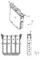
- FIG. 1 shows a modular storage system 2 for laboratory fluids (not shown) with a support frame 4, which is bent from sheet metal.
- the support frame 4 has a SBS standard format of a microplate on the underside (6). This allows the support frame 4 in the various positions, for example, a workstation 8 ( FIG. 3 ), but also in other intended for this connection measure laboratory devices form-fitting use.
- the support frame 4 again according to FIG. 1 has a total of seven slots 10 for laboratory vessel inserts 12 to 22 .
- the slots 10 numbered 1 and 2 are each equipped with the same laboratory vessel inserts 12 in the form of a low trough (see also FIG. 2 ), while the remaining slots 10 numbered 3 to 7 are each equipped by laboratory vessel inserts for at least four laboratory vessels.
- both the support frame 4 and the laboratory vessel inserts 12 to 28 have gripping structures, so that the support frame with inserted laboratory vessel inserts by means of a robotic gripper 9 (FIG. Fig. 4 ) of the workstation 8 is automatically and / or manually implemented and also the laboratory vessel inserts individually implement, so remove the frame and can be inserted into it.
- the laboratory vessel inserts 12 to 22 in the support frame 4 according to FIG. 1 as well as some in FIG. 1 not shown laboratory vessel inserts 24, 26 and 28 are in FIG. 2 such as each in three views also in FIGS. 5 to 13 shown. Visible, the laboratory vessel inserts 12 to 28 are each formed as tempering modules by each having a body 30 made of aluminum, which ensures uniform temperature distribution when the storage system 2 according to FIG. 1 is placed with its flat bottom 32 on a temperature control, for example, the tempering device 34 of the workstation 8 according to FIG.
- the bodies 30 of the inserts 12 to 28 of thermally conductive material surround the respective vessels (not shown in part) of each of the inserts 12 to 28 at least partially, thus directing the temperature from the tempering 34 in the liquid which is received in the respective vessel.
- each of said bodies is plane 30 on the underside, and the inserts protrude is inserted into the support frame 4, each connected to the body 30 on the underside of the frame 4 somewhat projecting, so that the inserts 12 to 22 are slightly raised by the tempering of the tempering 34 and support the Temperiertitle by its own weight.
- each of the laboratory vessel inserts contains 12 to 28 according to FIG. 2 at least one compartment 38 for a particular laboratory vessel 40: From left to right in FIG. 2 the insert has 24 (see also FIG. 5 ) two circular pockets 38 for cylindrical bulky vessels. One of these vessels 40 is in FIG. 2 shown in use 24 .
- the inserts 26, 14, 16 and 18 each have four slots (see also the FIGS. 6 to 9 ) Also for cylindrical laboratory vessels, but leaner than when using 24 Recognizable requires, like the insert 24 also the insert 26 because of its relatively large diameter of the compartments 38 a compared with the other inserts 12 to 22 and 28 double the width of the insert 24 and 26 .
- the inserts 20 and 22 have respective pockets 38 for eight laboratory vessels, likewise cylindrical, while finally have the inserts 12 and 28 pockets for a low (12) or a high (28) trough 40.
- the inserts according to FIG. 1 in the support frame 4 are arranged close together in a row next to each other, because in this way the tub container 40 of an insert 28 is heated by the tempering 30 of an adjacent insert with.
- Some of the inserts (18 to 22) have on top of their Multifunktionseinsteck Anlagenn 42 Deckelfixierstege 44 , which are capable of the film hinge lid, for example, the vessel 40 in the insert 22 in about 90 ° swiveled (ie vertically upwardly facing) lid position to keep.
- the film hinge lid of the vessel 40 is shown closed in the insert 22
- FIG. 9 Above
- the film hinge lid of the vessel 40 in the insert 22 in the 90 ° vertically upwardly facing position through the Deckelfixiersteg 44 is opened.
- Each of the slots 10 in the support frame 4 according to FIG. 1 has on both sides in the upper edge of the support frame 4, a Y-shaped notch in which at least one positioning lug 46 of the respective insert 12 to 28 is held positively.
- the Y-shaped notches laterally bound sheet metal tongues 48 of the upper edge of the support frame 4.
- the sheet metal tongues are on the side facing the viewer in FIG. 1 only as high as the Y-shaped notches 46, while being on the opposite, from the viewer in FIG. 1 opposite side (in FIG. 1 hidden by the inserts 12 to 22 ) by vertical cuts in the sheet metal wall 4, which extend the Y-shaped notches 46 downward, are extended in their height to resilient tongues.
- These spring tongues (not shown) clamp each of the inserts 12 to 22 in FIG FIG. 1 to the viewer against the tongues 48 in the front wall of the support frame 4 - which thus forms an aligned zero line to position the respective pockets of the inserts 12 to 22 highly accurate.
- the support frame 4 Along one of the two narrow sides (in FIG. 1 the right narrow side), the support frame 4, a further Y-shaped notch 50 , which makes a rotation of the frame by 180 °, for example in the form-fitting mounting of the tempering device 34 of the workstation 8 optically detectable.
- the inserts 12 to 28 have on one of the two narrow sides of the respective Multifunktionseinsteck Anlagen 42 Codierkerben 52 , which make the nature of each laboratory vessel insert clearly detectable by their unique position.
- a suitable, for example, optical sensor on the notch 52 can detect whether the insert is possibly inserted rotated by 180 ° in the support frame 4 .
Abstract
Description
Die vorliegende Erfindung betrifft ein modulares Aufbewahrungssystem für Labor-Flüssigkeiten.The present invention relates to a modular storage system for laboratory fluids.
Bisher bekannte Systeme zur Aufbewahrung von Proben sind primär an bestimmte Analysengeräte mit der Aufgabenstellung eines möglichst hohen Probendurchsatzes angepasst. Sie sind besonders im Bereich von klinischen Analysengeräten bekannt. Hier wird die Aufgabe gelöst, eine möglichst hohe Zahl von Proben aufzunehmen, zu lagern, zu verwalten und für Analysezwecke bereit zu halten. Entsprechend komplex sind diese Systeme konstruiert. Insbesondere ist bei diesen Systemen die Integration in komplexe, möglichst schnell ablaufende Analyseschritte kontaminationsfrei zu lösen. Auch steht die Notwendigkeit im Vordergrund, eine Verdunstung möglicherweise sehr teurer Reagenzien durch die Versiegelung der Reaktionsgefäße zu vermeiden.Previously known systems for storing samples are adapted primarily to certain analyzers with the task of the highest possible sample throughput. They are especially known in the field of clinical analyzers. Here, the task is solved, the highest possible number of samples to record, store, manage and keep ready for analysis purposes. Accordingly complex these systems are constructed. In particular, in these systems, the integration into complex, as fast as possible analytical steps to solve contamination-free. Also, the need to avoid the evaporation of possibly very expensive reagents by sealing the reaction vessels is in the foreground.
Entsprechende Ausführungsformen findet man zum Beispiel bei
Ähnlich ist die Aufgabenstellung in
Eine andere Aufgabenstellung aus dem medizinischen Bereich wird in
Um den klinischen Anforderungen an die Identifizierbarkeit von Proben gerecht zu werden, sind besonders bei klinischen Analysegeräten Mittel zur Erkennung von Proben, wie zum Beispiel Barcode- oder mechanische Abtastsysteme berücksichtigt, wie zum Beispiel in
Neueren Datums sind Vorrichtungen für den automatisierten Hochdurchsatz wie zum Beispiel
Eine andere Ausführungsform findet man in
In anderen Fällen wie zum Beispiel in
Es handelt sich bei den geschilderten Anwendungen primär um technisch aufwendige Lösungen, meist identische Typen von Proben analysegerecht langzeitlich zu verwahren, temporär einem Analyseautomaten zur Verfügung zu stellen und in ihre Ausgangsposition zurückzuführen. Die Systematik der Lagerhaltung von Flüssigkeiten erfordert hierbei den gleichen Typ von Gefäßen.It is in the described applications primarily to technically complex solutions, usually identical types of samples for analysis long-term safekeeping, temporary to provide an automatic analyzer and returned to their starting position. The system of storage of liquids here requires the same type of vessels.
Im allgemeinen Laborbereich dagegen stehen andere Ziele im Vordergrund. Moderne Workstations dienen dem programmierten Flüssigkeitshandling im Labor, und sie sind platzsparend ausgelegt. Sie zielen nicht auf Routineaufgabenstellungen wie zum Beispiel Lagerhaltung, klinische Analysen und/oder Hochdurchsatz ab. Dieses andere Aufgabensegment erfordert eine ständig wechselnde Bestückung mit Arbeitsmodulen wie zum Beispiel für Liquid-Handling-Stationen, Vakuumkammern, Thermal Cycler für die PCR (Polymerase Chain Reaction), Zentrifugen, Array Spotter oder andere Instrumente.In the general laboratory area, however, other goals are in the foreground. Modern workstations are used for programmed liquid handling in the laboratory, and they are designed to save space. They do not target routine tasks such as warehousing, clinical analysis and / or high throughput. This other task requires a constantly changing population of working modules such as Liquid Handling Stations, Vacuum Chambers, Polymerase Chain Reaction Thermal Cycles , Centrifuges, Array Spotters or other instruments.
Der Erfindung liegt die Aufgabenstellung zugrunde, für eine ständig wechselnde Arbeitsumgebung ein Aufbewahrungssystem für Flüssigkeiten oder andere Stoffe zu schaffen, welches flexibel, platzsparend, kostengünstig, vorzugsweise temperierbar, portabel und für eine Vielzahl unterschiedlicher Typen von Gefäßen und anderen Behältern geeignet ist.The invention has for its object to provide for a constantly changing work environment, a storage system for liquids or other substances, which is flexible, space-saving, inexpensive, preferably tempered, portable and suitable for a variety of different types of vessels and other containers.
Diese Aufgabe wird erfindungsgemäß von einem modularen Aufbewahrungssystem mit den Merkmalen des Anspruchs 1 gelöst. Bevorzugte Ausgestaltungen sind in den Unteransprüchen angegeben.This object is achieved by a modular storage system with the features of
Erfindungsgemäß weist ein modulares Aufbewahrungssystem für Labor-Flüssigkeiten einen Trägerrahmen sowie mindestens zwei verschiedene Laborgefäß-Einsätze auf, welche sich beliebig gegeneinander austauschbar und beliebig kombinierbar in den Trägerrahmen einsetzen lassen. Der Trägerrahmen weist zu diesem Zweck eine bestimmte Anzahl Steckplätze auf, die zum Formschluss mit den Laborgefäß-Einsätzen in ihrer Gestalt an diese Aufgabe angepasst sind. Die Laborgefäß-Einsätze weisen jeweils selbst direkt integriert mindestens ein Laborgefäß auf und/oder haben mindestens ein Steckfach für mindestens ein separates Laborgefäß. So können in dem erfindungsgemäßen Aufbewahrungssystem herkömmliche Laborgefäße ebenso untergebracht werden, wie zum Beispiel speziell für einen bestimmten Anwendungsfall in ihrem Volumen oder ihrer Geometrie angepasste. Und auch zukünftig auf dem Markt erscheinende Laborgefäße lassen sich in das Aufbewahrungssystem integrieren, indem dann dafür Laborgefäß-Einsätze mit einem entsprechend angepassten Steckfach konstruiert werden.According to the invention, a modular storage system for laboratory liquids has a support frame and at least two different laboratory vessel inserts, which can be used interchangeably and interchangeable with one another as desired in the support frame. The support frame has for this purpose a certain number of slots that are adapted for positive engagement with the laboratory vessel inserts in shape to this task. The laboratory vessel inserts have in each case directly integrated at least one laboratory vessel and / or have at least one compartment for at least one separate laboratory vessel. Thus, in the storage system according to the invention conventional laboratory vessels can be accommodated as well, for example, especially adapted for a particular application in volume or geometry. Laboratory vessels that will appear on the market in the future can also be integrated into the storage system by constructing laboratory vessel inserts with a suitably adapted compartment.
Das erfindungsgemäße Aufbewahrungssystem lässt sich leicht in die Arbeitsumgebung und Programmierung einer computergestützten Workstation für das Labor einbetten. Insbesondere ist es erfindungsgemäß vorteilhaft, dass die Integration einer Vielzahl von Laborbehältern chaotisch in die Aufnahmevorrichtung erfolgen kann, wobei sich die Behälter in Form, Durchmessergröße, Höhe, Material und Verschlussauslegung jeweils unterscheiden. Die hohe Interaktionsfähigkeit moderner Workstations wird durch die erfindungsgemäß selbsttätig mögliche Erkennung des Aufbewahrungssystems im Hinblick auf Position, Ausrichtung und Art der Systemkomponenten unterstützt. Proben können auf einer Solltemperatur gehalten werden, um zum Beispiel die Verdunstung der oft sehr kostbaren Substanzen zu erschweren und deren Haltbarkeit nicht zu beeinträchtigen. Deshalb ist es vorteilhaft möglich, eine Temperiereinrichtung in das Gesamtsystem zu integrieren.The storage system of the present invention is easy to embed into the work environment and programming of a computerized workstation for the laboratory. In particular, it is advantageous according to the invention that the integration of a multiplicity of laboratory containers can be carried out chaotically into the receiving device, wherein the containers differ in terms of shape, diameter size, height, material and closure design. The high interaction capability of modern workstations is supported by the inventively automatically possible detection of the storage system with regard to position, orientation and type of system components. Samples can be kept at a set temperature, for example, to make evaporation of the often very valuable substances difficult and not to impair their durability. Therefore, it is advantageously possible to integrate a tempering in the overall system.
Das Ziel der Erfindung ist eine Vorrichtung in Form eines vorzugsweise temperierbaren modularen Aufbewahrungssystems, welches auf einer kleinen Fläche die gleichzeitige Aufnahme verschiedenster Laborgefäße oder anderer Behälter in verschiedenster Form, Durchmesser und Höhe erlaubt. Die Gefäße können frei und unabhängig voneinander in das modulare Aufbewahrungssystem gebracht werden, sodass insgesamt der zur Verfügung stehende Raum optimal genutzt wird. Besonders in automatisierten Workstations im Laborbereich ist so der Zugriff auf extrem viele Gefäßtypen bei der gleichzeitigen Möglichkeit der Temperierung erreicht.The object of the invention is a device in the form of a preferably temperature-controlled modular storage system, which allows the simultaneous inclusion of various laboratory vessels or other containers in a variety of shape, diameter and height on a small area. The vessels can be freely and independently brought into the modular storage system, so that overall the available space is used optimally. Especially in automated workstations in the laboratory area, access to an extremely large number of vessel types is achieved with the simultaneous possibility of temperature control.
In vielen Laborprozessen ist die Aufbewahrung verbunden mit Kühlung, Aufheizung und Temperaturstabilisierung von Flüssigkeiten und anderen Stoffen unumgänglich. In vielen Fällen ist gleichzeitig eine große Anzahl unterschiedlichster Behälter für Proben auf kleinstmöglicher Fläche zu handhaben. Die Erfindung erlaubt endlich eine optimale Realisierung dieser Ziele. Der Begriff Behälter umfasst dabei alle im Labor verwendeten Gegenstände zur Aufnahme von festen oder flüssigen Stoffen.In many laboratory processes, storage associated with cooling, heating and temperature stabilization of liquids and other materials is inevitable. In many cases, a large number of different containers for samples on the smallest possible surface is to be handled at the same time. The invention finally allows optimal realization of these goals. The term container encompasses all objects used in the laboratory for receiving solid or liquid substances.
In einer Workstation-integrierten Temperiereinrichtung, kann das erfindungsgemäß Aufbewahrungssystem angeordnet werden. Das Aufbewahrungssystem besteht aus einem Modulrack, welches vorzugsweise unterschiedliche Temperiermodule aufnimmt. Jedes Temperiermodul hat vorzugsweise eine Multifunktionseinsteckhilfe an seinem oberen Ende und nimmt die zu temperierenden Behälter auf. Vorzugsweise ist das Aufbewahrungssystem in Gänze oder in Teilen autoklavierfest.In a workstation-integrated tempering device, the storage system according to the invention can be arranged. The storage system consists of a module rack, which preferably accommodates different temperature control modules. Each tempering module preferably has a multi-function plug-in aid at its upper end and receives the container to be tempered. Preferably, the storage system is fully autoclaved in whole or in part.
Der Begriff Temperiermodul meint hier erfindungsgemäße Laborgefäß-Einsätze mit einem Körper aus wärmeleitendem Werkstoff, der das mindestens eine Laborgefäß des Einsatzes mindestens teilweise umgibt. Dieser Körper ist unterseitig vorzugsweise plan, und die Einsätze springen, in den Trägerrahmen eingesetzt, mit dem Körper unterseitig aus dem Rahmen so vor, dass sie gemeinsam eine, vorzugsweise plane, Unterseite bilden. Diese Unterseite bildet dann die Kontaktfläche für die Temperieroberfläche einer Temperiereinrichtung. Aber auch ein Zurückspringen der Modulunterseiten im Trägerahmen ist erfindungsgemäß denkbar, wenn die Temperiereinrichtung ihrerseits eine passende Temperieroberfläche hat. Bevorzugt ist besonders, dass die Module von der Temperieroberfläche der Temperiereinrichtung beim Einsetzen des Trägerrahmens in die Temperiereinrichtung leicht angehoben werden, um den Oberflächenkontakt der Temperieroberfläche mit der Unterseite der Module insbesondere durch deren Eigengewicht sicherzustellen.The term Temperiermodul means here inventive laboratory vessel inserts with a body of thermally conductive material, which surrounds the at least one laboratory vessel of the insert at least partially. This body is preferably flat on the underside, and the inserts, inserted into the support frame, project with the body at the bottom of the frame so that together they form a, preferably plane, underside. This underside then forms the contact surface for the temperature control surface of a tempering device. But also a jump back The module bases in the support frame is conceivable according to the invention if the tempering device in turn has a suitable tempering surface. It is particularly preferred that the modules are slightly raised by the tempering of the tempering when inserting the support frame in the tempering to ensure the surface contact of the tempering with the bottom of the modules in particular by their own weight.
Der Begriff Temperiereinrichtung umfasst dem entsprechend alle im Labor verwendeten Vorrichtungen mit planaren oder sonstigen Oberflächenformen zur Erreichung des erforderlichen thermischen Übergangs. Die Temperiereinrichtung kann vorzugsweise aus Aluminium, Silber, oder anderen Metallen oder Legierungen gefertigt sein. Alternative Materialien sind hochleitfähige Kunststoffe sowie Beschichtungsmaterialien zum Beispiel mit Nanopartikeln.The term tempering accordingly includes all devices used in the laboratory with planar or other surface shapes to achieve the required thermal transition. The tempering device may preferably be made of aluminum, silver, or other metals or alloys. Alternative materials are highly conductive plastics as well as coating materials, for example with nanoparticles.
Durch die wahlfreie Anordnung der Temperiermodule im Modulrack können extrem viele verschiedenartige Behälter räumlich optimal aufgenommen werden. Über den thermischen Kontakt des Temperiermodules mit der Temperiereinrichtung werden durch Wärmeleitung die Proben in den Behältern auf eine gewünschte Temperatur oder einen Temperaturverlauf gebracht.Due to the optional arrangement of the temperature control modules in Modulrack extremely many different types of containers can be optimally accommodated in space. Via the thermal contact of the tempering module with the tempering device, the samples in the containers are brought to a desired temperature or a temperature profile by heat conduction.
Die Temperiereinrichtung ist vorzugsweise in einer Workstation so eingebaut, dass mittels geeigneter zum Beispiel formschlüssiger Aufnahmevorrichtung das Aufbewahrungssystem oder Teile davon manuell oder durch eine dafür geeignete robotische Transporteinrichtung formschlüssig auf die Temperiereinrichtung gesetzt werden kann. Temperatur und Temperaturverlauf sind zum Beispiel durch die Steuerungseinheit der Workstation programmierbar.The tempering device is preferably installed in a workstation in such a way that the storage system or parts thereof can be placed on the tempering device in a form-fitting manner by means of a suitable, for example, positive receiving device, manually or by means of a suitable robotic transport device. Temperature and temperature profile are programmable by the control unit of the workstation, for example.
Das Modulrack besteht bevorzugt aus einer quaderförmigen, aus einem Stück gefertigten, oben und unten offenen Halterung (Trägerrahmen). Alternativ sind auch mehrteilige Formen denkbar. Bevorzugt wird ein Format für die Grundfläche verwendet, welches mit dem Format einer oder mehrerer verbundener Mikroplatten (SBS) kompatibel ist. Veröffentlichte Standards für Microplates der Society for Biomelecular Screening (SBS) lauten zum Beispiel ANSI/SBS 1-2004, ANSI/SBS 2-2004,ANSI/SBS 3-2004,ANSI/SBS 4-2004. SBS befasst sich mit der Standardisierung von Mikroplatten, insbesondere um in der Laborautomation Entwicklungen zu erleichtern und dem Anwender größere Sicherheiten zu bieten.The Modulrack preferably consists of a cuboid, made of one piece, top and bottom open holder (support frame). Alternatively, multi-part shapes are conceivable. Preferably, a footprint format compatible with the format of one or more connected microplates (SBS) is used. Published standards for microplates of the Society for Biomelecular Screening (SBS) are, for example, ANSI / SBS 1-2004, ANSI / SBS 2-2004, ANSI / SBS 3-2004, ANSI / SBS 4-2004. SBS is concerned with the standardization of microplates, in particular to facilitate developments in laboratory automation and to provide greater security to the user.
Der der Temperiereinrichtung zugewandte Teil des Modulracks enthält vorzugsweise entsprechende Aufnahmeelemente zur Positionierung des Modulracks bezüglich der Temperiereinrichtung. Der obere Teil des Modulracks enthält vorzugsweise Einschnitte zur formschlüssigen und zentrierenden Aufnahme der Temperiermodule insbesondere mittels der Multifunktionseinsteckhilfen. Das Modulrack verfügt über Indizes zu dieser Erkennung seines Vorhandenseins in der Workstation und seiner Lage. In einer bevorzugten Ausführungsform dient in einer Workstation eine optische Leseeinrichtung mittels Laserdioden zur Erkennung. Es können aber auch andere Verfahren der Erkennung wie zum Beispiel Barcodes mit zugehörigem Scanner, mechanische Abtastsysteme, RFID-Tags mit Leser oder Verfahren der optischen Bildverarbeitung verwandt werden.The part of the module rack facing the tempering device preferably contains corresponding receiving elements for positioning the module rack with respect to the tempering device. The upper part of the module rack preferably contains notches for the positive and centering reception of the temperature control modules, in particular by means of the multi-function plug-in aids. The module rack has indexes for this detection of its presence in the workstation and its location. In a preferred embodiment, an optical reading device in a workstation is used for detecting by means of laser diodes. But it can also other methods of detection such as bar codes with associated scanner, mechanical scanning systems, RFID tags with reader or optical image processing methods are used.
Die vorzugsweise aus hoch wärmeleitendem Material oder gut wärmespeicherndem Material gefertigten Temperiermodule können auf ihrer Oberseite die Multifunktionseinsteckhilfe aufweisen. Die kleineren Seiten der Multifunktionseinsteckhilfe verfügen vorzugsweise über Positionierstege zur formschlüssigen Fixierung mit dem Modulrack. Die Temperiermodule können vorzugsweise aus Aluminium, Silber, oder anderen Metallen oder Legierungen gefertigt sein. Alternative Materialien sind hochleitfähige Kunststoffe sowie Beschichtungsmaterialien z. B. mittels Nanopartikel.The tempering modules, preferably made of highly heat-conductive material or good heat-storing material, may have the multi-function plug-in aid on their upper side. The smaller sides of the Multifunktionstecksteckhilfe preferably have positioning webs for positive fixing with the Modulrack. The tempering modules may preferably be made of aluminum, silver, or other metals or alloys. Alternative materials are highly conductive plastics and coating materials z. B. by nanoparticles.
Aber auch thermisch isolierende Laborgefäß-Einsätze können zu dem erfindungsgemäßen System gehören. Hier sind die Laborgefäße (oder die Steckfächer dafür) dann von einem isolierenden, thermisch gerade nicht hochleitfähigen Werkstoff-Körper umgeben.But also thermally insulating laboratory vessel inserts may belong to the system according to the invention. Here, the laboratory vessels (or the pockets for them) are then surrounded by an insulating, thermally just not highly conductive material body.
Die Positionierstege sind vorzugsweise mit Indizes oder Codierungen ausgestattet, welche die Erkennung des jeweiligen Typs des Temperiermodules erlauben. In einer bevorzugten Ausführungsform dient in einer Workstation eine optische Leseeinrichtung mittels Laserdioden auch zu dieser Erkennung. Es können aber auch hier andere Verfahren der Erkennung wie zum Beispiel Barcodes mit zugehörigem Scanner, mechanische Abtastsysteme, RFID-Tags mit Leser oder Verfahren der optischen Bildverarbeitung verwandt werden. In einer bevorzugten Ausführungsform bilden die Indizes optisch abtastbare Elemente, bevorzugt in Form von Kreisen oder Rechtecken oder anderen Formen. Alternativ können erhöhte oder vertiefte Strukturen zur mechanischen Abtastung verwendet werden. Zur Vermeidung von Lesefehlern werden bevorzugt redundante Codierungen verwandt. In einer bevorzugten Ausführungsform führt das Fehlen einer Codierung ("Nullcodierung") zur Ausführung einer Unterbrechungsroutine im Programm der Workstation, welche zum Beispiel entsprechende Schritte zur Fehlerbehebung veranlasst.The positioning webs are preferably equipped with indices or codings, which allow the detection of the respective type of tempering. In a preferred embodiment, an optical reading device is also used for this recognition in a workstation by means of laser diodes. However, other methods of detection such as bar codes with associated scanner, mechanical scanning systems, RFID tags with readers or methods of optical image processing can also be used here. In a preferred embodiment, the indices form optically scannable elements, preferably in the form of circles or rectangles or other shapes. Alternatively, raised or recessed structures may be used for mechanical scanning. To avoid read errors, preferably redundant codings are used. In a preferred embodiment, the absence of coding ("null coding") results in the execution of an interrupt routine in the program of the workstation which, for example, causes appropriate troubleshooting steps.
In einer bevorzugten Ausführungsform erlaubt die Codierung auf einem der Positionierstege die richtungsorientierte Erkennung der Temperiermodule, um zum Beispiel die Vertauschung von Behältern auszuschließen. In einer anderen Ausführungsform zum Beispiel für Testtubes mit Filmscharnier-Deckel ist die Positionierhilfe mit einem Deckel-Fixiersteg versehen. Der Fixiersteg enthält Einstecköffnungen zum Offenhalten der Deckel der Testtubes, um ein definiertes Anfahren der Gefäßöffnungen insbesondere zum Beispiel mit Automatenpipetten nicht durch die Deckel zu behindern.In a preferred embodiment, the coding on one of the positioning bars allows the direction-oriented detection of the temperature control modules, for example, to preclude the exchange of containers. In another embodiment, for example, for test tubes with film hinge lid, the positioning aid is provided with a lid Fixiersteg. The Fixiersteg contains insertion openings for holding open the lid of the test tubes in order not to hinder a defined start-up of the vessel openings, for example, with automatic dispensers through the lid.
Vorzugsweise sind die einzelnen Temperiermodule so masse- und formoptimiert, dass eine schnellstmögliche homogene Temperaturverteilung erzielt wird. Unter Masseoptimierung werden im Laborbereich konstruktive Merkmale verstanden, welche in Summe den Nutzen aus Wärmetransport und Wärmekapazität optimieren. Die Formoptierung unterstützt diesen Prozess durch die entsprechende dreidimensionale Gestaltung.The individual tempering modules are preferably optimized in terms of mass and shape in such a way that the fastest possible homogeneous temperature distribution is achieved. Under mass optimization, constructive features are understood in the laboratory area, which in total benefit Optimize heat transport and heat capacity. The form optics support this process by the corresponding three-dimensional design.
Die Multifunktionseinsteckhilfe verfügt über Öffnungen zur Aufnahme von Behältern in das Temperiermodul. Die Aufnahmekavitäten des Temperiermoduls können je nach Gestalt des aufzunehmenden Gefäßes verschieden in Höhe, Durchmesser, Abstand und Gestalt sein. Sie können auch nach unten offen sein, um zum Beispiel einen Reinigungs- oder Spülvorgang zu unterstützen. Vorzugsweise sind die Höhen der Aufnahmekavitäten so bemessen, dass die eingebrachten Gefäße randbündig aus der Multifunktionshilfe ragen. In einer bevorzugten Ausführungsform können verschieden lange aufzunehmende Behälter mittels seitlich einsteckbarer unterer Anschläge oberseitig auf gleiche Höhe gebracht werden. Bevorzugt ist auch die Multifunktionseinsteckhilfe aus autoklaviergeeigneten Material gefertigt.The multi-function plug-in aid has openings for holding containers in the temperature control module. The receiving cavities of the tempering module can be different in height, diameter, spacing and shape depending on the shape of the male vessel. They can also be open at the bottom, for example, to support a cleaning or rinsing process. Preferably, the heights of the receiving cavities are dimensioned such that the introduced vessels protrude flush from the multi-function aid. In a preferred embodiment, differently sized containers to be accommodated can be brought to the same height on the upper side by means of laterally insertable lower stops. Preferably, the Multifunktionseinsteckhilfe is made of autoklaviergeeigneten material.
Eine alternative oder ergänzende Verwendung des Aufbewahrungssystems besteht in der Verwendung als unabhängiges Aufbewahrungssystem auch außerhalb einer Workstation, zum Beispiel in Kühl- oder Gefriereinheiten, Inkubationseinheiten, zum Zwischenlagern von Produkten der Molekularbiologie, wie zum Beispiel dem temporären Lagern von Amplifikationsprodukten oder - reagenzien vor, während oder nach einem PCR-Prozess, zum temporären Lagern von Proteinen oder Antibodies oder anderen Produkten, oder zum Transport von Behältern zwischen verschiedenen Workstations oder innerhalb derselben oder auch in Labor-Straßen.An alternative or complementary use of the storage system is to use it as an independent storage system also outside of a workstation, for example in refrigerators or freezer units, incubation units, for intermediate storage of molecular biology products, such as temporarily storing amplification products or reagents before or after a PCR process, for temporary storage of proteins or Antibodies or other products, or for transporting containers between or within different workstations or even in laboratory streets.
Die Temperiereinrichtung für das System kann zusätzlich zur thermischen Funktion für das System mit weiteren Funktionen versehen sein, wie zum Beispiel mit Ergänzungsvorrichtungen zum Schütteln des Aufbewahrungssystems, um eine bessere Mischung der Proben in den Behältern sicherzustellen. Auch wird dadurch zum Beispiel die Auflösung von Feststoffen, wie zum Beispiel von Tabletten oder Material in Pulverform, unterstützt.The tempering device for the system may be provided with additional functions in addition to the thermal function of the system, such as supplementing devices for shaking the storage system to ensure better mixing of the samples in the containers. It also supports, for example, the dissolution of solids, such as tablets or material in powder form.
Das Modulrack kann anstelle von Temperiermodulen auch andere Module zur Prozessunterstützung im Labor aufnehmen, wie zum Beispiel Tanks für Flüssigkeiten oder Abfall. Andere bevorzugte Ausführungsformen der Laborgefäß-Einsätze oder Module sind zum Beispiel Vortex-Mischereinsätze für kleinere Laboraufgaben oder Einsätze für andere elektrische Kleingeräte zum Beispiel für Stofftrennung wie zum Beispiel für magnetische Beads in der Aufreinigung von DNA.The module rack can also accommodate other process support modules in the laboratory, such as tanks for liquids or waste, instead of temperature control modules. Other preferred embodiments of the laboratory vessel inserts or modules are, for example, vortex mixer inserts for smaller laboratory tasks or inserts for other small electrical appliances, for example for material separation, for example for magnetic beads in the purification of DNA.
Die bevorzugte Ausführungsform des Modulracks und der damit zusammengehörigen Komponenten ist in Quaderform. Eine bevorzugte Ausführungsform ist unterseitig passgenau zum Mikrotiterplattenformat (SBS). Es können aber auch alle anderen Formate, wie zum Beispiel kreisrunde Formen, typischerweise ringförmige Strukturen oder Karussells, verwendet werden.The preferred embodiment of the module rack and associated components is in cuboid shape. A preferred embodiment is suitable for the microtiter plate format (SBS) on the underside. However, all other formats, such as circular shapes, typically annular structures or carousels, may also be used.
Eine bevorzugte Ausgestaltung der Erfindung wird im folgenden mit Bezug auf die beigefügten Zeichnungen beispielhaft beschrieben.
-
Figur 1 - ist eine räumliche Ansicht eines erfindungsgemäßen modularen Aufbewahrungssystems für Laborflüssigkeiten mit einem Trägerrahmen und sieben Laborgefäß-Einsätzen,
-
Figur 2 - ist eine räumliche Ansicht von neun verschiedenen Laborgefäß-Einsätzen zum Teil mit Laborgefäßen in jeweiligen Steckfächern,
-
Figur 3 - ist eine räumliche Ansicht einer Workstation, in welcher das erfindungsgemäße Aufbewahrungssystem (nicht abgebildet) einsetzbar ist,
- Figur 4
- das erfindungsgemäße Aufbewahrungssystem gemäß
Figur 1 in räumlicher Ansicht an einem Greifer einer Workstation gemäßFigur 3 - Figur 5 bis 13
- jeweils oben in räumlicher Ansicht, unten links im Querschnitt und unten rechts in Seitenansicht die neun verschiedenen Laborgefäß-
Einsätze gemäß Figur 2 .
- FIG. 1
- Figure 3 is a perspective view of a modular laboratory fluid storage system of the present invention having a support frame and seven lab vessel inserts;
- FIG. 2
- is a three-dimensional view of nine different laboratory vessel inserts partly with laboratory vessels in respective slots,
- FIG. 3
- is a spatial view of a workstation in which the storage system according to the invention (not shown) can be used,
- FIG. 4
- the storage system according to the invention according to
FIG. 1 in a spatial view on a gripper of a workstation according toFIG. 3 and - FIGS. 5 to 13
- respectively in top view in spatial view, bottom left in cross-section and bottom right in side view of the nine different laboratory vessel inserts according to
FIG. 2 ,
Der Trägerrahmen 4 wieder gemäß
Für den Transport innerhalb der Workstation 8 weisen sowohl der Trägerrahmen 4 als auch jeweils die Laborgefäß-Einsätze 12 bis 28 Greifstrukturen auf, so dass der Trägerrahmen mit eingesetzten Laborgefäß-Einsätzen mittels eines robotischen Greifers 9 (
Die Laborgefäß-Einsätze 12 bis 22 in dem Trägerrahmen 4 gemäß
Wie gesagt enthält jeder der Laborgefäß-Einsätze 12 bis 28 gemäß
Einige der Einsätze (18 bis 22) weisen oberseitig an ihren Multifunktionseinsteckhilfen 42 Deckelfixierstege 44 auf, welche in der Lage sind, die Filmscharnier-Deckel zum Beispiel des Gefäßes 40 im Einsatz 22 in um 90° ausgeschwenkter (also senkrecht empor weisender) Deckelposition zu halten. In
Jeder der Steckplätze 10 im Trägerrahmen 4 gemäß
Entlang einer der beiden Schmalseiten (in
Claims (14)
Applications Claiming Priority (2)
| Application Number | Priority Date | Filing Date | Title |
|---|---|---|---|
| EP06754664A EP2035147B1 (en) | 2006-07-04 | 2006-07-04 | Modular storage system for laboratory fluids |
| PCT/EP2006/006508 WO2008003338A1 (en) | 2006-07-04 | 2006-07-04 | Modular storage system for laboratory fluids |
Related Parent Applications (2)
| Application Number | Title | Priority Date | Filing Date |
|---|---|---|---|
| EP06754664A Division EP2035147B1 (en) | 2006-07-04 | 2006-07-04 | Modular storage system for laboratory fluids |
| EP06754664.8 Division | 2006-07-04 |
Publications (2)
| Publication Number | Publication Date |
|---|---|
| EP2168684A1 true EP2168684A1 (en) | 2010-03-31 |
| EP2168684B1 EP2168684B1 (en) | 2012-09-05 |
Family
ID=36929041
Family Applications (3)
| Application Number | Title | Priority Date | Filing Date |
|---|---|---|---|
| EP09015626A Active EP2168684B1 (en) | 2006-07-04 | 2006-07-04 | Modular storage system for laboratory fluids |
| EP10009076A Withdrawn EP2260944A1 (en) | 2006-07-04 | 2006-07-04 | Modular storage system for laboratory liquids |
| EP06754664A Active EP2035147B1 (en) | 2006-07-04 | 2006-07-04 | Modular storage system for laboratory fluids |
Family Applications After (2)
| Application Number | Title | Priority Date | Filing Date |
|---|---|---|---|
| EP10009076A Withdrawn EP2260944A1 (en) | 2006-07-04 | 2006-07-04 | Modular storage system for laboratory liquids |
| EP06754664A Active EP2035147B1 (en) | 2006-07-04 | 2006-07-04 | Modular storage system for laboratory fluids |
Country Status (10)
| Country | Link |
|---|---|
| US (1) | US20100045147A1 (en) |
| EP (3) | EP2168684B1 (en) |
| JP (1) | JP5167258B2 (en) |
| KR (1) | KR20090110289A (en) |
| CN (1) | CN101479042B (en) |
| AT (1) | ATE457831T1 (en) |
| AU (1) | AU2006345918B2 (en) |
| CA (1) | CA2656651C (en) |
| DE (1) | DE502006006210D1 (en) |
| WO (1) | WO2008003338A1 (en) |
Families Citing this family (20)
| Publication number | Priority date | Publication date | Assignee | Title |
|---|---|---|---|---|
| JP5808524B2 (en) * | 2009-07-16 | 2015-11-10 | シスメックス株式会社 | Reagent container and reagent set |
| JP5933918B2 (en) * | 2009-12-10 | 2016-06-15 | エフ.ホフマン−ラ ロシュ アーゲーF. Hoffmann−La Roche Aktiengesellschaft | Mold-shaped locking system |
| JP4985792B2 (en) * | 2010-01-27 | 2012-07-25 | 株式会社日立プラントテクノロジー | Reagent cartridge for microorganism detection device |
| US8945479B2 (en) | 2010-07-26 | 2015-02-03 | Enplas Corporation | Microchannel chip and microanalysis system |
| EP2656918B1 (en) | 2012-04-27 | 2016-11-09 | Eppendorf AG | Kit |
| CN103111339B (en) * | 2013-03-06 | 2016-01-06 | 青岛大学医学院附属医院 | A kind of sample harvester |
| JP5832469B2 (en) | 2013-03-28 | 2015-12-16 | シスメックス株式会社 | Sample analyzer, transfer device and lid tray |
| JP6077992B2 (en) * | 2013-12-27 | 2017-02-08 | シスメックス株式会社 | Sample processing apparatus and rack |
| US20150204598A1 (en) * | 2014-01-20 | 2015-07-23 | Brooks Automation, Inc. | Portable cryogenic workstation |
| DE102016212609B3 (en) * | 2016-07-11 | 2017-06-08 | B Medical Systems S.à r.l. | Modular blood product storage system for the temperature-controlled storage of blood products |
| WO2018183896A1 (en) | 2017-03-31 | 2018-10-04 | Forward Biotech, Inc. | Device for measuring fluid volumes |
| EP3520897B1 (en) * | 2018-02-01 | 2023-10-04 | Beckman Coulter, Inc. | Configurable placement indication for sample tube rack receptacles |
| CN109116034B (en) * | 2018-08-30 | 2021-06-22 | 南京澳林生物科技有限公司 | Homocysteine detection kit with strong anti-interference performance |
| EP3666381B1 (en) | 2018-12-14 | 2022-02-09 | Eppendorf AG | Laboratory device for automatic treatment of laboratory samples |
| WO2020182795A1 (en) | 2019-03-14 | 2020-09-17 | Institut National De La Sante Et De La Recherche Médicale | Modular system for a pipetting machine |
| CN110918155B (en) * | 2019-12-11 | 2021-12-24 | 界首市人民医院 | Convenient cold-stored test tube placer |
| CN114165981A (en) * | 2020-09-11 | 2022-03-11 | Scl生物科技有限公司 | Active sample transport device |
| US11744242B2 (en) | 2020-09-17 | 2023-09-05 | Drsignal Biotechnology Co., Ltd. | Living body specimen transport device |
| CN114054120B (en) * | 2021-11-24 | 2022-10-11 | 哈尔滨星云医学检验所有限公司 | Laboratory automation system |
| WO2023170259A1 (en) * | 2022-03-11 | 2023-09-14 | Dna Script | Modular accessory rack |
Citations (13)
| Publication number | Priority date | Publication date | Assignee | Title |
|---|---|---|---|---|
| US4933146A (en) | 1986-07-11 | 1990-06-12 | Beckman Instruments, Inc. | Temperature control apparatus for automated clinical analyzer |
| EP0651254A1 (en) | 1993-10-28 | 1995-05-03 | F. Hoffmann-La Roche Ag | Reagent kit and analyser in which it may be used |
| US5589137A (en) | 1995-04-07 | 1996-12-31 | Lab-Interlink, Inc. | Specimen carrier |
| US5672317A (en) | 1995-04-19 | 1997-09-30 | Roche Diagnostics Systems, Inc. | Analyzer with fixed position bar code reader |
| US5788929A (en) | 1996-03-12 | 1998-08-04 | Nesti; Edmund D. | Sample temperature protection rack |
| WO2000045953A1 (en) | 1999-02-05 | 2000-08-10 | Bilatec Gesellschaft Zur Entwicklung Biotechnologischer Systeme Mbh | Device for selectively regulating the temperature of individual containers |
| US6156275A (en) | 1997-11-26 | 2000-12-05 | Bayer Corporation | Sample tube rack |
| US6432359B1 (en) | 1995-07-07 | 2002-08-13 | Bayer Corporation | Reagent handling system and configurable vial carrier for use therein |
| DE10203940A1 (en) * | 2002-02-01 | 2003-08-21 | Fraunhofer Ges Forschung | Plate for use in cryogenic storage of biological specimens has wells, into which specimens are placed, fits into cover in same way as drawer of matchbox, and is held in position by e.g. studs and recesses |
| WO2003100389A1 (en) * | 2002-05-28 | 2003-12-04 | Autogenomics, Inc. | Multi-reagent pack |
| US6669910B1 (en) * | 1997-08-07 | 2003-12-30 | Roche Diagnostics Gmbh | System for providing biological materials |
| DE10333545A1 (en) | 2003-07-23 | 2005-04-14 | Hte Ag The High Throughput Experimentation Company | Modular sample holder, to hold and prepare samples for analysis, has a module with sample holders held in a second module in turn held in a third module |
| US20060012773A1 (en) | 2002-11-20 | 2006-01-19 | Karin Schutze | Sample holder for a reception device receiving biological objects and microscope system designed to operate using one such sample holder |
Family Cites Families (19)
| Publication number | Priority date | Publication date | Assignee | Title |
|---|---|---|---|---|
| JPS626534Y2 (en) * | 1979-06-08 | 1987-02-14 | ||
| JPH0124628Y2 (en) * | 1981-05-21 | 1989-07-25 | ||
| JPS63502929A (en) * | 1986-03-20 | 1988-10-27 | ベックマン インスツルメンツ インコーポレーテッド | modular storage system |
| US4683782A (en) * | 1986-11-17 | 1987-08-04 | Warburg Richard J | Microcentrifuge tube opener |
| JPH01214764A (en) * | 1988-02-24 | 1989-08-29 | Toshiba Corp | Automatic chemical analysis apparatus |
| US5009316A (en) * | 1988-03-29 | 1991-04-23 | Klein David C | Test tube cassette system and cassettes for use therein |
| CA2130517C (en) * | 1993-09-10 | 1999-10-05 | Walter Fassbind | Array of reaction containers for an apparatus for automatic performance of temperature cycles |
| JP3985872B2 (en) * | 1995-07-31 | 2007-10-03 | プレシジョン・システム・サイエンス株式会社 | container |
| US5687849A (en) * | 1996-04-23 | 1997-11-18 | Coulter International Corp. | Test tube cassette for accommodating different tube sizes |
| US5861563A (en) * | 1997-03-20 | 1999-01-19 | Bayer Corporation | Automatic closed tube sampler |
| DE69841255D1 (en) * | 1997-11-14 | 2009-12-03 | Gen Probe Inc | Implement for analysis |
| JP2001113184A (en) * | 1999-10-19 | 2001-04-24 | Ichiro Kojima | Metallic block for heating test tube |
| JP4209679B2 (en) * | 2001-01-26 | 2009-01-14 | テカン・トレーディング・アクチェンゲゼルシャフト | Holding device |
| US6790413B2 (en) * | 2001-05-03 | 2004-09-14 | Beckman Coulter, Inc. | Sample presentation unit |
| EP1417033A4 (en) * | 2001-08-16 | 2010-06-23 | Ge Healthcare Bio Sciences Ab | Fixtures for use in parallel processing bio-chips |
| US7000785B2 (en) * | 2003-04-03 | 2006-02-21 | Bio-Rad Laboratories, Inc. | Tube rack accommodating a range of tube diameters |
| US7553671B2 (en) * | 2004-05-25 | 2009-06-30 | Vertex Pharmaceuticals, Inc. | Modular test tube rack |
| AU2005254503A1 (en) * | 2004-06-10 | 2005-12-29 | Gilson, Inc. | Sample collection container rack overlays |
| US7799283B2 (en) * | 2004-11-12 | 2010-09-21 | Ortho-Clinical Diagnostics, Inc. | Heating and cooling multiple containers or multi-chamber containers |
-
2006
- 2006-07-04 CN CN2006800552138A patent/CN101479042B/en active Active
- 2006-07-04 EP EP09015626A patent/EP2168684B1/en active Active
- 2006-07-04 JP JP2009516911A patent/JP5167258B2/en active Active
- 2006-07-04 US US12/306,026 patent/US20100045147A1/en not_active Abandoned
- 2006-07-04 EP EP10009076A patent/EP2260944A1/en not_active Withdrawn
- 2006-07-04 AT AT06754664T patent/ATE457831T1/en active
- 2006-07-04 WO PCT/EP2006/006508 patent/WO2008003338A1/en active Application Filing
- 2006-07-04 KR KR1020097000076A patent/KR20090110289A/en not_active Application Discontinuation
- 2006-07-04 AU AU2006345918A patent/AU2006345918B2/en active Active
- 2006-07-04 CA CA2656651A patent/CA2656651C/en active Active
- 2006-07-04 EP EP06754664A patent/EP2035147B1/en active Active
- 2006-07-04 DE DE502006006210T patent/DE502006006210D1/en active Active
Patent Citations (13)
| Publication number | Priority date | Publication date | Assignee | Title |
|---|---|---|---|---|
| US4933146A (en) | 1986-07-11 | 1990-06-12 | Beckman Instruments, Inc. | Temperature control apparatus for automated clinical analyzer |
| EP0651254A1 (en) | 1993-10-28 | 1995-05-03 | F. Hoffmann-La Roche Ag | Reagent kit and analyser in which it may be used |
| US5589137A (en) | 1995-04-07 | 1996-12-31 | Lab-Interlink, Inc. | Specimen carrier |
| US5672317A (en) | 1995-04-19 | 1997-09-30 | Roche Diagnostics Systems, Inc. | Analyzer with fixed position bar code reader |
| US6432359B1 (en) | 1995-07-07 | 2002-08-13 | Bayer Corporation | Reagent handling system and configurable vial carrier for use therein |
| US5788929A (en) | 1996-03-12 | 1998-08-04 | Nesti; Edmund D. | Sample temperature protection rack |
| US6669910B1 (en) * | 1997-08-07 | 2003-12-30 | Roche Diagnostics Gmbh | System for providing biological materials |
| US6156275A (en) | 1997-11-26 | 2000-12-05 | Bayer Corporation | Sample tube rack |
| WO2000045953A1 (en) | 1999-02-05 | 2000-08-10 | Bilatec Gesellschaft Zur Entwicklung Biotechnologischer Systeme Mbh | Device for selectively regulating the temperature of individual containers |
| DE10203940A1 (en) * | 2002-02-01 | 2003-08-21 | Fraunhofer Ges Forschung | Plate for use in cryogenic storage of biological specimens has wells, into which specimens are placed, fits into cover in same way as drawer of matchbox, and is held in position by e.g. studs and recesses |
| WO2003100389A1 (en) * | 2002-05-28 | 2003-12-04 | Autogenomics, Inc. | Multi-reagent pack |
| US20060012773A1 (en) | 2002-11-20 | 2006-01-19 | Karin Schutze | Sample holder for a reception device receiving biological objects and microscope system designed to operate using one such sample holder |
| DE10333545A1 (en) | 2003-07-23 | 2005-04-14 | Hte Ag The High Throughput Experimentation Company | Modular sample holder, to hold and prepare samples for analysis, has a module with sample holders held in a second module in turn held in a third module |
Also Published As
| Publication number | Publication date |
|---|---|
| JP2009541038A (en) | 2009-11-26 |
| CA2656651A1 (en) | 2008-01-10 |
| JP5167258B2 (en) | 2013-03-21 |
| CN101479042A (en) | 2009-07-08 |
| WO2008003338A1 (en) | 2008-01-10 |
| KR20090110289A (en) | 2009-10-21 |
| AU2006345918A1 (en) | 2008-01-10 |
| EP2168684B1 (en) | 2012-09-05 |
| ATE457831T1 (en) | 2010-03-15 |
| CN101479042B (en) | 2012-08-08 |
| AU2006345918B2 (en) | 2013-06-13 |
| CA2656651C (en) | 2013-09-10 |
| EP2035147B1 (en) | 2010-02-17 |
| EP2260944A1 (en) | 2010-12-15 |
| DE502006006210D1 (en) | 2010-04-01 |
| US20100045147A1 (en) | 2010-02-25 |
| EP2035147A1 (en) | 2009-03-18 |
Similar Documents
| Publication | Publication Date | Title |
|---|---|---|
| EP2168684B1 (en) | Modular storage system for laboratory fluids | |
| US7829028B2 (en) | Storage unit and transfer system for storing and providing biological samples | |
| AU2007356959B2 (en) | Collection/extraction container for biological material in forensic samples | |
| DE102010053913A1 (en) | Method for separating and detecting an analyte | |
| US6921513B2 (en) | System for processing samples in a multichamber arrangement | |
| US20030129755A1 (en) | System and method of storing and retrieving storage elements | |
| CN107884343B (en) | Analysis system with accurately positioned multi-well plates | |
| US20110152128A1 (en) | Enhanced microplate configurations | |
| US11268885B2 (en) | Sample collection device | |
| EP3259071B1 (en) | Sample vessel rack, method for locking sample vessels in a sample vessel rack and sample vessel rack system | |
| CN110573254A (en) | Cap assembly and associated method of use | |
| JP7000282B2 (en) | Rack positioning system | |
| US20060210451A1 (en) | Fixtures for use in parallel processing bio-chips | |
| EP2656918B1 (en) | Kit | |
| EP3032265A1 (en) | Device for storing of fluid containers | |
| US7550291B2 (en) | Vessel system for the treatment and/or storage of liquids |
Legal Events
| Date | Code | Title | Description |
|---|---|---|---|
| PUAI | Public reference made under article 153(3) epc to a published international application that has entered the european phase |
Free format text: ORIGINAL CODE: 0009012 |
|
| 17P | Request for examination filed |
Effective date: 20091228 |
|
| AC | Divisional application: reference to earlier application |
Ref document number: 2035147 Country of ref document: EP Kind code of ref document: P |
|
| AK | Designated contracting states |
Kind code of ref document: A1 Designated state(s): AT BE BG CH CY CZ DE DK EE ES FI FR GB GR HU IE IS IT LI LT LU LV MC NL PL PT RO SE SI SK TR |
|
| 17Q | First examination report despatched |
Effective date: 20101019 |
|
| GRAP | Despatch of communication of intention to grant a patent |
Free format text: ORIGINAL CODE: EPIDOSNIGR1 |
|
| RIC1 | Information provided on ipc code assigned before grant |
Ipc: B01L 3/00 20060101ALI20120116BHEP Ipc: B01L 9/00 20060101AFI20120116BHEP Ipc: C12M 1/00 20060101ALI20120116BHEP Ipc: B01L 9/06 20060101ALI20120116BHEP Ipc: G01N 35/02 20060101ALI20120116BHEP |
|
| GRAS | Grant fee paid |
Free format text: ORIGINAL CODE: EPIDOSNIGR3 |
|
| GRAA | (expected) grant |
Free format text: ORIGINAL CODE: 0009210 |
|
| AC | Divisional application: reference to earlier application |
Ref document number: 2035147 Country of ref document: EP Kind code of ref document: P |
|
| AK | Designated contracting states |
Kind code of ref document: B1 Designated state(s): AT BE BG CH CY CZ DE DK EE ES FI FR GB GR HU IE IS IT LI LT LU LV MC NL PL PT RO SE SI SK TR |
|
| REG | Reference to a national code |
Ref country code: GB Ref legal event code: FG4D Free format text: NOT ENGLISH |
|
| REG | Reference to a national code |
Ref country code: CH Ref legal event code: NV Representative=s name: KELLER & PARTNER PATENTANWAELTE AG Ref country code: CH Ref legal event code: EP |
|
| REG | Reference to a national code |
Ref country code: AT Ref legal event code: REF Ref document number: 573836 Country of ref document: AT Kind code of ref document: T Effective date: 20120915 |
|
| REG | Reference to a national code |
Ref country code: IE Ref legal event code: FG4D Free format text: LANGUAGE OF EP DOCUMENT: GERMAN |
|
| REG | Reference to a national code |
Ref country code: DE Ref legal event code: R096 Ref document number: 502006011954 Country of ref document: DE Effective date: 20121031 |
|
| REG | Reference to a national code |
Ref country code: NL Ref legal event code: VDEP Effective date: 20120905 |
|
| PG25 | Lapsed in a contracting state [announced via postgrant information from national office to epo] |
Ref country code: CY Free format text: LAPSE BECAUSE OF FAILURE TO SUBMIT A TRANSLATION OF THE DESCRIPTION OR TO PAY THE FEE WITHIN THE PRESCRIBED TIME-LIMIT Effective date: 20120905 Ref country code: FI Free format text: LAPSE BECAUSE OF FAILURE TO SUBMIT A TRANSLATION OF THE DESCRIPTION OR TO PAY THE FEE WITHIN THE PRESCRIBED TIME-LIMIT Effective date: 20120905 Ref country code: LT Free format text: LAPSE BECAUSE OF FAILURE TO SUBMIT A TRANSLATION OF THE DESCRIPTION OR TO PAY THE FEE WITHIN THE PRESCRIBED TIME-LIMIT Effective date: 20120905 |
|
| REG | Reference to a national code |
Ref country code: LT Ref legal event code: MG4D Effective date: 20120905 |
|
| PG25 | Lapsed in a contracting state [announced via postgrant information from national office to epo] |
Ref country code: GR Free format text: LAPSE BECAUSE OF FAILURE TO SUBMIT A TRANSLATION OF THE DESCRIPTION OR TO PAY THE FEE WITHIN THE PRESCRIBED TIME-LIMIT Effective date: 20121206 Ref country code: SI Free format text: LAPSE BECAUSE OF FAILURE TO SUBMIT A TRANSLATION OF THE DESCRIPTION OR TO PAY THE FEE WITHIN THE PRESCRIBED TIME-LIMIT Effective date: 20120905 Ref country code: LV Free format text: LAPSE BECAUSE OF FAILURE TO SUBMIT A TRANSLATION OF THE DESCRIPTION OR TO PAY THE FEE WITHIN THE PRESCRIBED TIME-LIMIT Effective date: 20120905 Ref country code: SE Free format text: LAPSE BECAUSE OF FAILURE TO SUBMIT A TRANSLATION OF THE DESCRIPTION OR TO PAY THE FEE WITHIN THE PRESCRIBED TIME-LIMIT Effective date: 20120905 |
|
| PG25 | Lapsed in a contracting state [announced via postgrant information from national office to epo] |
Ref country code: CZ Free format text: LAPSE BECAUSE OF FAILURE TO SUBMIT A TRANSLATION OF THE DESCRIPTION OR TO PAY THE FEE WITHIN THE PRESCRIBED TIME-LIMIT Effective date: 20120905 Ref country code: IS Free format text: LAPSE BECAUSE OF FAILURE TO SUBMIT A TRANSLATION OF THE DESCRIPTION OR TO PAY THE FEE WITHIN THE PRESCRIBED TIME-LIMIT Effective date: 20130105 Ref country code: EE Free format text: LAPSE BECAUSE OF FAILURE TO SUBMIT A TRANSLATION OF THE DESCRIPTION OR TO PAY THE FEE WITHIN THE PRESCRIBED TIME-LIMIT Effective date: 20120905 Ref country code: RO Free format text: LAPSE BECAUSE OF FAILURE TO SUBMIT A TRANSLATION OF THE DESCRIPTION OR TO PAY THE FEE WITHIN THE PRESCRIBED TIME-LIMIT Effective date: 20120905 Ref country code: ES Free format text: LAPSE BECAUSE OF FAILURE TO SUBMIT A TRANSLATION OF THE DESCRIPTION OR TO PAY THE FEE WITHIN THE PRESCRIBED TIME-LIMIT Effective date: 20121216 Ref country code: NL Free format text: LAPSE BECAUSE OF FAILURE TO SUBMIT A TRANSLATION OF THE DESCRIPTION OR TO PAY THE FEE WITHIN THE PRESCRIBED TIME-LIMIT Effective date: 20120905 |
|
| PG25 | Lapsed in a contracting state [announced via postgrant information from national office to epo] |
Ref country code: SK Free format text: LAPSE BECAUSE OF FAILURE TO SUBMIT A TRANSLATION OF THE DESCRIPTION OR TO PAY THE FEE WITHIN THE PRESCRIBED TIME-LIMIT Effective date: 20120905 Ref country code: PL Free format text: LAPSE BECAUSE OF FAILURE TO SUBMIT A TRANSLATION OF THE DESCRIPTION OR TO PAY THE FEE WITHIN THE PRESCRIBED TIME-LIMIT Effective date: 20120905 Ref country code: PT Free format text: LAPSE BECAUSE OF FAILURE TO SUBMIT A TRANSLATION OF THE DESCRIPTION OR TO PAY THE FEE WITHIN THE PRESCRIBED TIME-LIMIT Effective date: 20130107 |
|
| PLBE | No opposition filed within time limit |
Free format text: ORIGINAL CODE: 0009261 |
|
| STAA | Information on the status of an ep patent application or granted ep patent |
Free format text: STATUS: NO OPPOSITION FILED WITHIN TIME LIMIT |
|
| PG25 | Lapsed in a contracting state [announced via postgrant information from national office to epo] |
Ref country code: BG Free format text: LAPSE BECAUSE OF FAILURE TO SUBMIT A TRANSLATION OF THE DESCRIPTION OR TO PAY THE FEE WITHIN THE PRESCRIBED TIME-LIMIT Effective date: 20121205 Ref country code: DK Free format text: LAPSE BECAUSE OF FAILURE TO SUBMIT A TRANSLATION OF THE DESCRIPTION OR TO PAY THE FEE WITHIN THE PRESCRIBED TIME-LIMIT Effective date: 20120905 |
|
| 26N | No opposition filed |
Effective date: 20130606 |
|
| REG | Reference to a national code |
Ref country code: DE Ref legal event code: R097 Ref document number: 502006011954 Country of ref document: DE Effective date: 20130606 |
|
| BERE | Be: lapsed |
Owner name: EPPENDORF A.G. Effective date: 20130731 |
|
| PG25 | Lapsed in a contracting state [announced via postgrant information from national office to epo] |
Ref country code: MC Free format text: LAPSE BECAUSE OF FAILURE TO SUBMIT A TRANSLATION OF THE DESCRIPTION OR TO PAY THE FEE WITHIN THE PRESCRIBED TIME-LIMIT Effective date: 20120905 |
|
| REG | Reference to a national code |
Ref country code: IE Ref legal event code: MM4A |
|
| PG25 | Lapsed in a contracting state [announced via postgrant information from national office to epo] |
Ref country code: BE Free format text: LAPSE BECAUSE OF NON-PAYMENT OF DUE FEES Effective date: 20130731 |
|
| PG25 | Lapsed in a contracting state [announced via postgrant information from national office to epo] |
Ref country code: IE Free format text: LAPSE BECAUSE OF NON-PAYMENT OF DUE FEES Effective date: 20130704 |
|
| REG | Reference to a national code |
Ref country code: AT Ref legal event code: MM01 Ref document number: 573836 Country of ref document: AT Kind code of ref document: T Effective date: 20130704 |
|
| PG25 | Lapsed in a contracting state [announced via postgrant information from national office to epo] |
Ref country code: AT Free format text: LAPSE BECAUSE OF NON-PAYMENT OF DUE FEES Effective date: 20130704 |
|
| REG | Reference to a national code |
Ref country code: CH Ref legal event code: PCAR Free format text: NEW ADDRESS: EIGERSTRASSE 2 POSTFACH, 3000 BERN 14 (CH) |
|
| PG25 | Lapsed in a contracting state [announced via postgrant information from national office to epo] |
Ref country code: TR Free format text: LAPSE BECAUSE OF FAILURE TO SUBMIT A TRANSLATION OF THE DESCRIPTION OR TO PAY THE FEE WITHIN THE PRESCRIBED TIME-LIMIT Effective date: 20120905 |
|
| PG25 | Lapsed in a contracting state [announced via postgrant information from national office to epo] |
Ref country code: HU Free format text: LAPSE BECAUSE OF FAILURE TO SUBMIT A TRANSLATION OF THE DESCRIPTION OR TO PAY THE FEE WITHIN THE PRESCRIBED TIME-LIMIT; INVALID AB INITIO Effective date: 20060704 Ref country code: LU Free format text: LAPSE BECAUSE OF NON-PAYMENT OF DUE FEES Effective date: 20130704 |
|
| REG | Reference to a national code |
Ref country code: FR Ref legal event code: PLFP Year of fee payment: 11 |
|
| REG | Reference to a national code |
Ref country code: FR Ref legal event code: PLFP Year of fee payment: 12 |
|
| REG | Reference to a national code |
Ref country code: FR Ref legal event code: PLFP Year of fee payment: 13 |
|
| REG | Reference to a national code |
Ref country code: CH Ref legal event code: PFA Owner name: EPPENDORF AG, DE Free format text: FORMER OWNER: EPPENDORF AG, DE |
|
| REG | Reference to a national code |
Ref country code: FR Ref legal event code: PLFP Year of fee payment: 17 |
|
| REG | Reference to a national code |
Ref country code: DE Ref legal event code: R081 Ref document number: 502006011954 Country of ref document: DE Owner name: EPPENDORF SE, DE Free format text: FORMER OWNER: EPPENDORF AG, 22339 HAMBURG, DE |
|
| P01 | Opt-out of the competence of the unified patent court (upc) registered |
Effective date: 20230527 |
|
| PGFP | Annual fee paid to national office [announced via postgrant information from national office to epo] |
Ref country code: IT Payment date: 20230719 Year of fee payment: 18 Ref country code: GB Payment date: 20230720 Year of fee payment: 18 Ref country code: CH Payment date: 20230801 Year of fee payment: 18 |
|
| PGFP | Annual fee paid to national office [announced via postgrant information from national office to epo] |
Ref country code: FR Payment date: 20230725 Year of fee payment: 18 Ref country code: DE Payment date: 20230719 Year of fee payment: 18 |