EP2156806A1 - Implantation device for soft tissue markers and other implants - Google Patents
Implantation device for soft tissue markers and other implants Download PDFInfo
- Publication number
- EP2156806A1 EP2156806A1 EP09009287A EP09009287A EP2156806A1 EP 2156806 A1 EP2156806 A1 EP 2156806A1 EP 09009287 A EP09009287 A EP 09009287A EP 09009287 A EP09009287 A EP 09009287A EP 2156806 A1 EP2156806 A1 EP 2156806A1
- Authority
- EP
- European Patent Office
- Prior art keywords
- implant
- cannulus
- restraining element
- channel
- distal end
- Prior art date
- Legal status (The legal status is an assumption and is not a legal conclusion. Google has not performed a legal analysis and makes no representation as to the accuracy of the status listed.)
- Withdrawn
Links
Images

Classifications
-
- A—HUMAN NECESSITIES
- A61—MEDICAL OR VETERINARY SCIENCE; HYGIENE
- A61M—DEVICES FOR INTRODUCING MEDIA INTO, OR ONTO, THE BODY; DEVICES FOR TRANSDUCING BODY MEDIA OR FOR TAKING MEDIA FROM THE BODY; DEVICES FOR PRODUCING OR ENDING SLEEP OR STUPOR
- A61M37/00—Other apparatus for introducing media into the body; Percutany, i.e. introducing medicines into the body by diffusion through the skin
- A61M37/0069—Devices for implanting pellets, e.g. markers or solid medicaments
-
- A—HUMAN NECESSITIES
- A61—MEDICAL OR VETERINARY SCIENCE; HYGIENE
- A61B—DIAGNOSIS; SURGERY; IDENTIFICATION
- A61B90/00—Instruments, implements or accessories specially adapted for surgery or diagnosis and not covered by any of the groups A61B1/00 - A61B50/00, e.g. for luxation treatment or for protecting wound edges
- A61B90/39—Markers, e.g. radio-opaque or breast lesions markers
- A61B2090/3904—Markers, e.g. radio-opaque or breast lesions markers specially adapted for marking specified tissue
- A61B2090/3908—Soft tissue, e.g. breast tissue
-
- A—HUMAN NECESSITIES
- A61—MEDICAL OR VETERINARY SCIENCE; HYGIENE
- A61B—DIAGNOSIS; SURGERY; IDENTIFICATION
- A61B90/00—Instruments, implements or accessories specially adapted for surgery or diagnosis and not covered by any of the groups A61B1/00 - A61B50/00, e.g. for luxation treatment or for protecting wound edges
- A61B90/39—Markers, e.g. radio-opaque or breast lesions markers
- A61B2090/3987—Applicators for implanting markers
Definitions
- Provisional Application 60/600,725 filed on August 12, 2004 entitled “Medical Navigation System Based on Differential Sensor”
- U.S. Provisional Application 60/619,792 filed on October 19, 2004 entitled “Using a Catheter or Guidewire Tracking System to Provide Positional Feedback for an Automated Catheter or Guidewire Navigation System”
- U.S. Provisional Application 60/619,897 filed on October 19, 2004 entitled “Using a Radioactive Source as the Tracked Element of a Tracking System”
- the present invention in some embodiments thereof, relates to a device for inserting medical implants into tissue and, more particularly, but not exclusively, to a device for inserting soft tissue markers.
- Soft tissue implants include markers that are used to mark the site of a biopsy or another surgical procedure or medical treatment, for defining the location of the procedure or treatment before it is performed, or for marking a location where the procedure or treatment was performed, for future follow up medical procedures.
- Soft tissue implants also include therapeutic implants, for example for brachytherapy.
- the implant whether it is used as a marker or for another purpose, is often inserted using a device that comprises a hollow needle or other cannulus structure, with a sharpened end for penetrating to a desired location in the tissue, and with the implant loaded intro a channel inside the cannulus.
- the device may or may not be part of an instrument that is also used for the surgery or biopsy.
- the device sometimes has an obstruction that prevents the implant from accidentally leaving the device before the operator of the device is ready to implant it, so that it can be positioned precisely, and means for removing or circumventing the obstruction, and inserting the implant into the tissue, when it is properly positioned.
- An example of such a device with an obstruction is shown in Figs. 1A-1C , and described below.
- US patent 6,402,677 to Jacobs , describes a device for inserting brachytherapy seeds into soft tissue.
- the seeds are placed in a cannulus, which has an end that is partly blocked by an obstruction.
- a stylet pushes the brachytherapy seeds with enough force to go past the obstruction, and leave the cannulus.
- Soft tissue markers as well as brachytherapy implants, are sometimes formed in the shape of a helical coil.
- Such implants are described, for example, in US patents 6,261,243 and 7,047,063 , cited above, and in published patent application US2004/0073107 to Sioshansi , as well as published application WO00/24332 to Cortese , and US patent 6,371,904 to Sirimanne .
- An aspect of an embodiment of the invention concerns a device for inserting an easily deformed medical implant, with a restraining element that keeps the implant from leaving the device accidentally, but allows the implant to leave the device when relatively little force is exerted on it, so it will not be damaged.
- a device for inserting into body tissue an implant with a medical function, with a channel passing at least partly through the implant comprising:
- the implant is a soft tissue marker.
- the implant comprises a helical coil.
- the channel of the implant extends all the way through the implant.
- the restraining element has a distal end that extends past the distal end of the implant when the implant and pusher are so situated, but not past the distal end of the cannulus, and the distal end of the restraining element restrains the implant from sliding off the restraining element.
- the distal end of the restraining element bends to one side, but is flexible enough to straighten sufficiently so that the implant can slide off it, when the implant is pushed with said force.
- the restraining element comprises a wire.
- a distal end of the restraining element is enlarged, but is configured so that the implant can slide off it, when the implant is pushed with said force.
- the restraining element restrains the implant by friction against a surface of the channel of the implant.
- the function of the implant comprises folding on itself to define a volume with a smallest dimension greater than the diameter of the channel of the cannulus, when the implant is inserted into the tissue.
- the restraining element is least indirectly coupled to the cannulus, such that the restraining element does not move along the cannulus when the pusher pushes the implant through the distal end of the cannulus.
- the device also includes a handle, wherein the cannulus and the restraining element are anchored in the handle at their proximal ends.
- the device also includes a handle adapted to be held by an operator with one hand when using the device to insert the implant in the tissue.
- a method of inserting a medical implant into tissue comprising:
- proper functioning of the implant in the tissue comprises the implant folding on itself, when inserted into the tissue, to define a volume with smallest dimension greater than the diameter of the cannulus.
- the present invention in some embodiments thereof, relates to a device for inserting medical implants into tissue and, more particularly, but not exclusively, to a device for inserting soft tissue markers.
- An aspect of an embodiment of the invention concerns a device with a cannulus, for inserting a medical implant, for example a soft tissue marker, into soft tissue, and with a restraining element that restrains the implant from leaving the device accidentally, but allows the implant to be pushed gently out of the device into the tissue.
- the restraining element extends at least part way through a channel in the implant, and through a channel in a pusher, situated behind the implant, that pushes the implant out of the cannulus, and the restraining element is optionally directly or indirectly anchored to the cannulus. The pushing needed to overcome the restraint of the restraining element is gentle enough so that the implant is not damaged, and can still perform its function in the tissue.
- the implant is a soft tissue marker that is designed to fold on itself, as a result of the force it encounters when it is inserted into the tissue, defining a volume that is greater in diameter than the channel of the cannulus, making the marker more stable within the tissue and more visible in medical imaging.
- markers are described in related patent application PCT/IL2007/000214 , cited above.
- the implant is easily deformable, it may be advantageous not to push on it too hard before it is inserted into the tissue.
- the restraining element is a wire that extends through the channel in the implant to its distal end, and has a bend at the end that restrains the implant from sliding off it and exiting the cannulus, but the wire is flexible enough, and the channel in the implant is wide enough, so that the implant can be pushed past the bent end of the wire with relatively little force.
- the restraining element uses friction with the channel through the implant, in order to restrain the implant from moving past it.
- prior methods of restraining an implant before it is ready to be implanted are generally not well suited to an implant that is designed to fold on itself and define an increased volume, when it leaves the cannulus.
- a relatively large force is generally applied to the implant.
- a large pushing force is generally needed, because the plug or other barrier is designed not to fail accidentally. If the implant is easily deformable, as it may tend to be if it is designed to fold on itself when it exits the cannulus, then the large pushing force may deform the implant before it leaves the cannulus.
- Such deformation may actually prevent the implant from leaving the cannulus, and if it does leave the cannulus, it may not fold properly after it leaves the cannulus.
- Such an implant may also not fold on itself if the cannulus is pulled away from the implant, rather than pushing the implant out of the cannulus. And having such an implant exit the cannulus from an opening on the side may also not to be suitable, since it may not fold properly.
- a potential advantage of using a restraining element that is anchored to the cannulus, and passes through a channel in the implant and in the pushing elements, is that the restraining element cannot easily break off or otherwise fail, but only a small force may be needed to overcome the restraining element when the implant is pushed out of the cannulus. This behavior is in contrast to that of a wax plug, for example, which may easily break off prematurely, if it requires only a small force to push it off the cannulus.
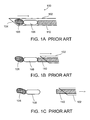
- FIG. 1A device 100 for inserting a soft tissue implant, as illustrated in Figures 1A-1C .
- device 100 comprises a cannulus 102, with a distal end 104 that is sharpened for penetrating into the tissue, and is open. The opening of end 104 is sealed by a plug 106, made of bone wax, for example.
- An implant 108 such as a marker or a brachytherapy seed, is loaded behind plug 106 in cannulus 102, with a stylet 110 extending from the proximal end of cannulus 102 up to implant 108.
- Plug 106 prevents implant 108 from leaving cannulus 102 accidentally, before the cannulus is in position for inserting the implant. Once the cannulus is properly positioned, it is pulled back, as shown in Fig. 1B , while stylet 110 is held in place, leaving plug 106 and implant 108 in place.
- Cannulus 102 is pulled back with sufficient force that it becomes detached from plug 106, allowing plug 106 and implant 108 to leave cannulus 102 through distal end 104.
- plug 106 is attached firmly to cannulus 102 initially, in order to ensure that plug 106 does not come off prematurely.
- Cannulus 102, with stylet 110, is then removed from the tissue, leaving plug 106 and implant 108 in the tissue.
- cannulus 102 is held in place, while stylet 110 pushes implant 108 and plug 106 forward, out of cannulus 102 through distal end 104.
- This may require even more force than pulling the cannulus back, since the marker and plug must overcome the pressure of the tissue, in addition to the force needed to detach the plug from the cannulus.
- the end result is the same, with the marker and plug remaining in the tissue.
- the device and method shown in Figs. 1A-1C may not be suitable for inserting an implant of a type that is designed to fold on itself when it is inserted into the tissue.
- the plug which is left in the tissue, may be more difficult to sterilize than the marker, and it may irritate the tissue, even if it is eventually absorbed.
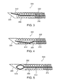
- Fig. 2A shows a device 200 for inserting an implant into soft tissue, according to an exemplary embodiment of the invention.
- Device 200 comprises a cannulus 202 with a sharpened open end 204, similar to cannulus 102. There is no plug blocking the open end of cannulus 202.
- An implant 208 for example a helical marker, is placed near the distal end of cannulus 202, with a pusher 210 behind it. Both implant 208 and pusher 210 have channels running through them.
- a restraining element 212 extends through the channels of pusher 210 and implant 208, optionally extending past the distal end of implant 208. In the configuration shown in Fig.
- restraining element 212 is a wire, bent at its distal end, and this bend keeps implant 208 from sliding off restraining element 212, and out distal end 204, prematurely.
- the distal end of restraining element 212 touches the wall of cannulus 202, leaving no space for implant 208 to slide past it. Even if the distal end of restraining element 212 does not extend all the way to the wall, it may restrain implant 208 from moving past it by getting in its way, or by friction.
- restraining element 212 is anchored to cannulus 202, for example at their proximal end at a handle that is used to hold device 200, or at least indirectly coupled to cannulus 202, such that restraining element 212 does not move along cannulus 202 when pusher 210 pushes implant 208 along cannulus 202.
- implant 208 moves forward, over restraining element 212. Relatively little force is needed to make implant 208 do this, since it takes relatively little force to slightly decrease the bend in restraining element 212, so implant 208 can fit over it. Although implant 208 may compress somewhat even from this relatively small force, it does not deform to such an extent, when it is still inside cannulus 202, that it will be unable to fold on itself when it leaves cannulus 202.
- the force needed to push the implant past the restraining element is greater than the weight of the implant, or greater than 2 times or 5 times or 10 times or 20 times or 50 times or 100 times the weight of the implant.
- the weight of the implant is, for example, 0.5 milligrams, or 1 milligram, or 2 milligrams, or 5 milligrams, 10 milligrams, or a greater or lesser or intermediate weight.
- the force needed to overcome the restraining element is less than a force needed to deform the implant irreversibly.
- the force needed to overcome the restraining element plus the greatest force that would normally be needed to overcome any friction of the implant with the cannulus, is less than a force needed to deform the implant irreversibly, or at least less than a force needed to deform the implant irreversibly to such an extent that it will not fold properly when it leaves the cannulus.
- Fig. 2C shows device 200 when implant 208 has been completely pushed out of cannulus 202. Due to the pressure of the tissue, implant 208 has folded on itself, as it is designed to do, forming a generally irregular shape defining a volume that is wider, in its smallest dimension, than the inside diameter of the cannulus. Restraining element 212 is now completely inside the channel of pusher 210, but is flexible enough so that it can unbend enough to fit inside the channel of pusher 210, without the need to exert very much force on it. Device 200 can then be withdrawn from the tissue, leaving implant 208 in place in the tissue.
- Restraining element 212 is optionally stiff enough so that its distal bend will not unbend under the weight of implant 208 during handling of the device, allowing implant 208 to fall out if device 200 is held with distal end 204 facing downward. But restraining element is flexible enough so that it will unbend in response to a force on implant 208 that will not prevent implant 208 from functioning properly when it is inserted in the tissue, folding on itself to form an increased volume.
- Figs. 3 and 4 show implant devices 300 and 400 with alternative designs for the restraining element.
- a restraining element 312 has a gentle curvature, optionally over its whole length, or at least over a portion that is outside the channel of pusher 210. The curvature is sufficiently great that, over the length of restraining element 312 that is initially outside the channel of pusher 210, the distal end of restraining element 312 reaches the wall of cannulus 202, or sufficiently close to the wall of cannulus 202 that implant 208 cannot easily slide off restraining element 312.
- the distal end of restraining element 312 extends radially past the surface of the channel through implant 208, so that element 312 blocks implant 208 from sliding off it, at least when there is sufficiently little force pushing it.
- the portion of restraining element 312 outside pusher 210 gets shorter.
- the distal end of restraining element 312 moves closer to the center of the channel of cannulus 202.
- implant 208 can move past restraining element 312 and out of end 204 of cannulus 202, into the tissue.
- a restraining element 412 has a bend downward, near the point where it emerges from the channel of pushing element 210, and then curves upward for the rest of its length.
- the force of restraining element 412 pushing implant 208 against the wall of cannulus 202 at the bottom of Fig. 4 tends to prevent implant 208 from moving, due to friction of implant 208 with the wall of cannulus 202.
- the force of friction is, for example, a coefficient of friction times the force with which element 412 pushes implant 208 against the wall.
- this force of friction is more than great enough to prevent implant 208 from sliding along restraining element 412 under its own weight, but is small enough so that implant 208 can be pushed off restraining element 412, and out of cannulus 202 into the tissue, with a relatively small force exerted by pusher 210.
- this force is small enough so that implant 208 will not deform so much that it cannot function properly when it is inserted into the tissue, as explained previously.
- the end of the restraining element need not extend past the end of implant 208, but the end of the restraining element can restrain implant 208 from moving by friction between the restraining element and the inner surface of implant 208, and/or by pushing implant 208 against the inner surface of cannulus 202, and using friction between implant 208 and cannulus 202 to restrain implant 208 from sliding out of cannulus 202.
- a restraining element 512 has an enlarged end 514, optionally compressible, which prevents implant 208 from sliding off restraining element 512 before implanting, for example because of friction, or because enlarged end 514 has too great a diameter for implant 208 to slide past.
- pusher 210 pushes implant 208 with enough force so that is slides past enlarged end 514, optionally by compressing enlarged end 514.
- the required force to push implant 208 past enlarged end 514 is small enough so that implant 208 is not damaged, but still functions properly in the tissue.
- Enlarged end 514 could have a number of different possible configurations, and the shape shown in Fig. 5 is only exemplary.
- enlarged end 514 comprises a flexible or compressible structure which can be compressed radially toward the axis of cannulus 202, allowing implant 208 to go past restraining element 512, when pusher 210 pushes implant 208 forward.
- enlarged end 514 optionally comprises two or more rod-like extensions extending radially or obliquely away from the axis of element 512 in different directions.
- enlarged end 514 comprises a set of two or more leaf springs, or similar structures which can be pressed toward the axis by implant 208.
- enlarged end 514 comprises a balloon, optionally a compressible balloon. Additionally or alternatively, enlarged end 514 comprises a compressible sponge-like material. Additionally or alternatively, whether enlarged end 514 is compressible or relatively rigid, enlarged end 514 just fits within implant 208 as implant 208 slides past it, such that the force of friction prevents implant 208 from sliding off enlarged end 514 unless implant 208 is pushed with sufficient force by pusher 210.
- Implant 208 in the form of a coil is Figs. 2A-5 is merely exemplary, and implant 208 need not be in the form of a coil, but can be of any configuration with a channel into which the restraining element extends.
- the implant may comprise a cylindrical shell, optionally with perforations in the shell, or with accordion-like folds in the shell.
- the perforations comprise most or almost all of the area of the shell.
- the channel through the implant does not extend through the whole length of the implant, but is blocked at the distal end, or at another location, and the restraining element does not extend distally past the location where the channel is blocked.
- the channel through the implant is not completely surrounded by the implant azimuthally, but is open in one direction, with the channel comprising an axially oriented slot or indentation in the implant.
- the geometry of the implant, the restraining element and the cannulus prevents the restraining element from slipping out of the channel of the implant, when the implant is still in the cannulus.
- a helical implant, with the end turns of the helix open is a special case of such a geometry, with the "slot" being the spiral space between adjacent turns of the helix.
- the implant is a cylindrical shell, or a helical coil with closed end turns
- the implant topologically surrounds the restraining element, which cannot slip out of the channel of the implant except by moving forward off the distal end of the restraining element.
- the implant exerts a radially inward force on the restraining element as it is moving past it, on the way out of the cannulus, and conversely the restraining element exerts a radially outward force on the implant.
- This has the potential advantage that it may help to maintain the shape of the implant, and prevent it from deforming, when it is being pushed out of the cannulus. Possibly this outward radial force on the implant could allow the implant to be pushed with greater force axially, without deforming it to an extent that it wouldn't fold properly when it leaves the cannulus.
- composition or method may include additional ingredients and/or steps, but only if the additional ingredients and/or steps do not materially alter the basic and novel characteristics of the claimed composition or method.
- a compound or “at least one compound” may include a plurality of compounds, including mixtures thereof.
- range format is merely for convenience and brevity and should not be construed as an inflexible limitation on the scope of the invention. Accordingly, the description of a range should be considered to have specifically disclosed all the possible subranges as well as individual numerical values within that range. For example, description of a range such as from 1 to 6 should be considered to have specifically disclosed subranges such as from 1 to 3, from 1 to 4, from 1 to 5, from 2 to 4, from 2 to 6, from 3 to 6 etc., as well as individual numbers within that range, for example, 1, 2, 3, 4, 5, and 6. This applies regardless of the breadth of the range.
Abstract
A device for inserting into body tissue an implant (208) with a medical function, with a channel passing at least partly through the implant, the device comprising:
a) a cannulus (202) with a distal end, and with a channel sized to hold the implant;
b) a pusher (210) with a channel passing through it, the pusher sized to be situated inside the channel of the cannulus behind the implant, and adapted to push the implant through the distal end of the cannulus into the tissue;
c) a restraining element (212) that extends through the channel of the pusher and at least partly through the channel of the implant when they are so situated in the channel of the cannulus, which restrains the implant from accidentally exiting the cannulus, but allows the implant to exit the distal end of the cannulus when it is pushed with a force small enough so as not to damage the function of the implant in the tissue.
Description
- This application is related to International Patent Application
PCT/IL2007/000214 filed on February 15, 2007 PCT/IB2006/052771 filed on August 10, 2006 , entitled "Medical Treatment System and Method," and of International Patent ApplicationPCT IB2006/052770 filed on August 10, 2006 and entitled "Localization of a Radioactive Source," and which claims priority fromU.S. Provisional Applications 60/773,931 filed on February 16, 2006 60/773,930 filed February 16, 2006 60/804,178 filed on June 8, 2006 PCT/IL2005/000871 filed on August 11, 2005 PCT/IL2005/001101 filed on October 19, 2005 U.S. Provisional Application 60/600,725 filed on August 12, 2004 U.S. Provisional Application 60/619,792 filed on October 19, 2004 U.S. Provisional Application 60/619,897 filed on October 19, 2004 U.S. Provisional Application 60/619,898 filed on October 19, 2004 US Patent Application 11/463,664 filed on August 10, 2006 US Patent Application 11/463,659 filed on August 10, 2006 - The disclosure of each of these applications is fully incorporated herein by reference.
- The present invention, in some embodiments thereof, relates to a device for inserting medical implants into tissue and, more particularly, but not exclusively, to a device for inserting soft tissue markers.
- Soft tissue implants include markers that are used to mark the site of a biopsy or another surgical procedure or medical treatment, for defining the location of the procedure or treatment before it is performed, or for marking a location where the procedure or treatment was performed, for future follow up medical procedures. Soft tissue implants also include therapeutic implants, for example for brachytherapy. The implant, whether it is used as a marker or for another purpose, is often inserted using a device that comprises a hollow needle or other cannulus structure, with a sharpened end for penetrating to a desired location in the tissue, and with the implant loaded intro a channel inside the cannulus. The device may or may not be part of an instrument that is also used for the surgery or biopsy. The device sometimes has an obstruction that prevents the implant from accidentally leaving the device before the operator of the device is ready to implant it, so that it can be positioned precisely, and means for removing or circumventing the obstruction, and inserting the implant into the tissue, when it is properly positioned. An example of such a device with an obstruction is shown in
Figs. 1A-1C , and described below. -
US patent 6,261,243, to Burney et al , describes a cannulus for inserting a soft tissue marker, with an opening in the side of the cannulus. A sliding cover prevents the marker from leaving the cannulus until the cannulus is properly positioned. - Published patent application
US2004/0236213, to Jones et al , describes a device with a cannulus holding a soft tissue marker, and a plug made of wax covering an opening at the end. The marker is pushed from behind by a stylet, which pushes hard enough to push the plug out of the cannulus, allowing the marker to emerge. - A similar device is described in
US patent 7,247,160 to Seiler et al , but instead of pushing the marker and the plug forward out of the cannulus, the cannulus is pulled back, while using the stylet to hold the marker and plug in place. This breaks the plug free from the cannulus, leaving the marker and the plug is place in the tissue, and may allow more accurate placement of the marker than if the cannulus is held in place and the marker and plug are pushed forward. -
US patent 7,047,063, to Burbank , describes a device for inserting a marker into soft tissue, in which the marker is placed in a cannulus that has a closed petalled end. When the marker is pushed from behind by a stylet, the marker pushes open the petals at the end of the cannulus, allowing the marker to emerge. -
US patent 6,402,677, to Jacobs , describes a device for inserting brachytherapy seeds into soft tissue. The seeds are placed in a cannulus, which has an end that is partly blocked by an obstruction. A stylet pushes the brachytherapy seeds with enough force to go past the obstruction, and leave the cannulus. - Soft tissue markers, as well as brachytherapy implants, are sometimes formed in the shape of a helical coil. Such implants are described, for example, in
US patents 6,261,243 and7,047,063 , cited above, and in published patent applicationUS2004/0073107 to Sioshansi , as well as published applicationWO00/24332 to Cortese US patent 6,371,904 to Sirimanne . - An aspect of an embodiment of the invention concerns a device for inserting an easily deformed medical implant, with a restraining element that keeps the implant from leaving the device accidentally, but allows the implant to leave the device when relatively little force is exerted on it, so it will not be damaged.
- There is thus provided, in accordance with an exemplary embodiment of the invention, a device for inserting into body tissue an implant with a medical function, with a channel passing at least partly through the implant, the device comprising:
- a) a cannulus with a distal end, and with a channel sized to hold the implant;
- b) a pusher with a channel passing through it, the pusher sized to be situated inside the channel of the cannulus behind the implant, and adapted to push the implant through the distal end of the cannulus into the tissue;
- c) a restraining element that extends through the channel of the pusher and at least partly through the channel of the implant when they are so situated in the channel of the cannulus, which restrains the implant from accidentally exiting the cannulus, but allows the implant to exit the distal end of the cannulus when it is pushed with a force small enough so as not to damage the function of the implant in the tissue.
- Optionally, the implant is a soft tissue marker.
- Optionally, the implant comprises a helical coil.
- Optionally, the channel of the implant extends all the way through the implant.
- Optionally, the restraining element has a distal end that extends past the distal end of the implant when the implant and pusher are so situated, but not past the distal end of the cannulus, and the distal end of the restraining element restrains the implant from sliding off the restraining element.
- Optionally, the distal end of the restraining element bends to one side, but is flexible enough to straighten sufficiently so that the implant can slide off it, when the implant is pushed with said force.
- In an embodiment of the invention, the restraining element comprises a wire.
- Optionally, a distal end of the restraining element is enlarged, but is configured so that the implant can slide off it, when the implant is pushed with said force.
- Optionally, the restraining element restrains the implant by friction against a surface of the channel of the implant.
- In an embodiment of the invention, the function of the implant comprises folding on itself to define a volume with a smallest dimension greater than the diameter of the channel of the cannulus, when the implant is inserted into the tissue.
- Optionally, the restraining element is least indirectly coupled to the cannulus, such that the restraining element does not move along the cannulus when the pusher pushes the implant through the distal end of the cannulus.
- Optionally, the device also includes a handle, wherein the cannulus and the restraining element are anchored in the handle at their proximal ends.
- Optionally, the device also includes a handle adapted to be held by an operator with one hand when using the device to insert the implant in the tissue.
- There is further provided, in accordance with an exemplary embodiment of the invention, a method of inserting a medical implant into tissue, comprising:
- a) loading the implant into a channel of a cannulus, with a restraining element extending at least part way through a channel in the implant, restraining the implant from leaving the cannulus accidentally before insertion into the tissue;
- b) inserting a distal end of the cannulus into the tissue; and
- c) pushing the implant out of the distal end of the cannulus, with a large enough force so that the implant moves past the restraining element, but with a small enough force so that the implant is not damaged and functions properly in the tissue.
- Optionally, proper functioning of the implant in the tissue comprises the implant folding on itself, when inserted into the tissue, to define a volume with smallest dimension greater than the diameter of the cannulus.
- Unless otherwise defined, all technical and/or scientific terms used herein have the same meaning as commonly understood by one of ordinary skill in the art to which the invention pertains. Although methods and materials similar or equivalent to those described herein can be used in the practice or testing of embodiments of the invention, exemplary methods and/or materials are described below. In case of conflict, the patent specification, including definitions, will control. In addition, the materials, methods, and examples are illustrative only and are not intended to be necessarily limiting.
- Some embodiments of the invention are herein described, by way of example only, with reference to the accompanying drawings. With specific reference now to the drawings in detail, it is stressed that the particulars shown are by way of example and for purposes of illustrative discussion of embodiments of the invention. In this regard, the description taken with the drawings makes apparent to those skilled in the art how embodiments of the invention may be practiced.
- In the drawings:
-
FIGS. 1A-1C schematically show a time sequence of inserting a marker or other implant in soft tissue, according to the prior art; -
FIGS. 2A-2C schematically show a time sequence of inserting a marker in soft tissue, according to an exemplary embodiment of the invention; -
FIG. 3 schematically shows a device for inserting a marker into soft tissue, according to another exemplary embodiment of the invention; -
FIG. 4 schematically shows a device for inserting a marker into soft tissue, according to another exemplary embodiment of the invention; and -
FIG. 5 schematically shows a device for inserting a marker into soft tissue, according to another exemplary embodiment of the invention. - The present invention, in some embodiments thereof, relates to a device for inserting medical implants into tissue and, more particularly, but not exclusively, to a device for inserting soft tissue markers.
- An aspect of an embodiment of the invention concerns a device with a cannulus, for inserting a medical implant, for example a soft tissue marker, into soft tissue, and with a restraining element that restrains the implant from leaving the device accidentally, but allows the implant to be pushed gently out of the device into the tissue. The restraining element extends at least part way through a channel in the implant, and through a channel in a pusher, situated behind the implant, that pushes the implant out of the cannulus, and the restraining element is optionally directly or indirectly anchored to the cannulus. The pushing needed to overcome the restraint of the restraining element is gentle enough so that the implant is not damaged, and can still perform its function in the tissue. For example, the implant is a soft tissue marker that is designed to fold on itself, as a result of the force it encounters when it is inserted into the tissue, defining a volume that is greater in diameter than the channel of the cannulus, making the marker more stable within the tissue and more visible in medical imaging. Such markers are described in related patent application
PCT/IL2007/000214 - Optionally, the restraining element is a wire that extends through the channel in the implant to its distal end, and has a bend at the end that restrains the implant from sliding off it and exiting the cannulus, but the wire is flexible enough, and the channel in the implant is wide enough, so that the implant can be pushed past the bent end of the wire with relatively little force. Optionally, whether or not the restraining element extends to the distal end of the implant, it uses friction with the channel through the implant, in order to restrain the implant from moving past it.
- It should be noted that prior methods of restraining an implant before it is ready to be implanted, such as those described above, are generally not well suited to an implant that is designed to fold on itself and define an increased volume, when it leaves the cannulus. When the implant has to push against a wax plug, or a petalled end, for example, in order to exit the cannulus, a relatively large force is generally applied to the implant. A large pushing force is generally needed, because the plug or other barrier is designed not to fail accidentally. If the implant is easily deformable, as it may tend to be if it is designed to fold on itself when it exits the cannulus, then the large pushing force may deform the implant before it leaves the cannulus. Such deformation may actually prevent the implant from leaving the cannulus, and if it does leave the cannulus, it may not fold properly after it leaves the cannulus. Such an implant may also not fold on itself if the cannulus is pulled away from the implant, rather than pushing the implant out of the cannulus. And having such an implant exit the cannulus from an opening on the side may also not to be suitable, since it may not fold properly.
- A potential advantage of using a restraining element that is anchored to the cannulus, and passes through a channel in the implant and in the pushing elements, is that the restraining element cannot easily break off or otherwise fail, but only a small force may be needed to overcome the restraining element when the implant is pushed out of the cannulus. This behavior is in contrast to that of a wax plug, for example, which may easily break off prematurely, if it requires only a small force to push it off the cannulus.
- For purposes of better understanding some embodiments of the present invention, as illustrated in
Figures 2A-5 of the drawings, reference is first made to the construction and operation of a conventional (i.e., prior art)device 100 for inserting a soft tissue implant, as illustrated inFigures 1A-1C . As seen inFig. 1A ,device 100 comprises acannulus 102, with adistal end 104 that is sharpened for penetrating into the tissue, and is open. The opening ofend 104 is sealed by aplug 106, made of bone wax, for example. Animplant 108, such as a marker or a brachytherapy seed, is loaded behindplug 106 incannulus 102, with astylet 110 extending from the proximal end ofcannulus 102 up toimplant 108.Plug 106 preventsimplant 108 from leavingcannulus 102 accidentally, before the cannulus is in position for inserting the implant. Once the cannulus is properly positioned, it is pulled back, as shown inFig. 1B , whilestylet 110 is held in place, leavingplug 106 andimplant 108 in place.Cannulus 102 is pulled back with sufficient force that it becomes detached fromplug 106, allowingplug 106 andimplant 108 to leavecannulus 102 throughdistal end 104. This requires a relatively large force, becauseplug 106 is attached firmly to cannulus 102 initially, in order to ensure thatplug 106 does not come off prematurely.Cannulus 102, withstylet 110, is then removed from the tissue, leavingplug 106 andimplant 108 in the tissue. - In other prior art devices,
cannulus 102 is held in place, whilestylet 110 pushesimplant 108 and plug 106 forward, out ofcannulus 102 throughdistal end 104. This may require even more force than pulling the cannulus back, since the marker and plug must overcome the pressure of the tissue, in addition to the force needed to detach the plug from the cannulus. The end result is the same, with the marker and plug remaining in the tissue. - As noted above, the device and method shown in
Figs. 1A-1C may not be suitable for inserting an implant of a type that is designed to fold on itself when it is inserted into the tissue. The plug, which is left in the tissue, may be more difficult to sterilize than the marker, and it may irritate the tissue, even if it is eventually absorbed. - Before explaining at least one embodiment of the invention in detail, it is to be understood that the invention is not necessarily limited in its application to the details of construction and the arrangement of the components and/or methods set forth in the following description and/or illustrated in the drawings and/or the Examples. The invention is capable of other embodiments or of being practiced or carried out in various ways.
- Referring now to the drawings,
Fig. 2A shows adevice 200 for inserting an implant into soft tissue, according to an exemplary embodiment of the invention.Device 200 comprises acannulus 202 with a sharpenedopen end 204, similar tocannulus 102. There is no plug blocking the open end ofcannulus 202. Animplant 208, for example a helical marker, is placed near the distal end ofcannulus 202, with apusher 210 behind it. Bothimplant 208 andpusher 210 have channels running through them. A restrainingelement 212 extends through the channels ofpusher 210 andimplant 208, optionally extending past the distal end ofimplant 208. In the configuration shown inFig. 2A , restrainingelement 212 is a wire, bent at its distal end, and this bend keepsimplant 208 from sliding off restrainingelement 212, and outdistal end 204, prematurely. Optionally, the distal end of restrainingelement 212 touches the wall ofcannulus 202, leaving no space forimplant 208 to slide past it. Even if the distal end of restrainingelement 212 does not extend all the way to the wall, it may restrainimplant 208 from moving past it by getting in its way, or by friction. - When
device 200 has been positioned in the soft tissue, at a location whereimplant 208 is to be inserted, thenpusher 210 is pushed forward againstimplant 208, as shown inFig. 2B , whilecannulus 202 and restrainingelement 212 do not move forward. Optionally, restrainingelement 212 is anchored to cannulus 202, for example at their proximal end at a handle that is used to holddevice 200, or at least indirectly coupled tocannulus 202, such that restrainingelement 212 does not move alongcannulus 202 whenpusher 210 pushes implant 208 alongcannulus 202. - When
pusher 210 is pushed forward againstimplant 208,implant 208 moves forward, over restrainingelement 212. Relatively little force is needed to makeimplant 208 do this, since it takes relatively little force to slightly decrease the bend in restrainingelement 212, so implant 208 can fit over it. Althoughimplant 208 may compress somewhat even from this relatively small force, it does not deform to such an extent, when it is still insidecannulus 202, that it will be unable to fold on itself when it leavescannulus 202. - Optionally, the force needed to push the implant past the restraining element, in
device 200 or any other embodiment of the invention, is greater than the weight of the implant, or greater than 2 times or 5 times or 10 times or 20 times or 50 times or 100 times the weight of the implant. The weight of the implant is, for example, 0.5 milligrams, or 1 milligram, or 2 milligrams, or 5 milligrams, 10 milligrams, or a greater or lesser or intermediate weight. Optionally, the force needed to overcome the restraining element is less than a force needed to deform the implant irreversibly. Optionally the force needed to overcome the restraining element, plus the greatest force that would normally be needed to overcome any friction of the implant with the cannulus, is less than a force needed to deform the implant irreversibly, or at least less than a force needed to deform the implant irreversibly to such an extent that it will not fold properly when it leaves the cannulus. -
Fig. 2C showsdevice 200 whenimplant 208 has been completely pushed out ofcannulus 202. Due to the pressure of the tissue,implant 208 has folded on itself, as it is designed to do, forming a generally irregular shape defining a volume that is wider, in its smallest dimension, than the inside diameter of the cannulus. Restrainingelement 212 is now completely inside the channel ofpusher 210, but is flexible enough so that it can unbend enough to fit inside the channel ofpusher 210, without the need to exert very much force on it.Device 200 can then be withdrawn from the tissue, leavingimplant 208 in place in the tissue. - Restraining
element 212 is optionally stiff enough so that its distal bend will not unbend under the weight ofimplant 208 during handling of the device, allowingimplant 208 to fall out ifdevice 200 is held withdistal end 204 facing downward. But restraining element is flexible enough so that it will unbend in response to a force onimplant 208 that will not preventimplant 208 from functioning properly when it is inserted in the tissue, folding on itself to form an increased volume. -
Figs. 3 and 4 show implant devices Fig. 3 , a restrainingelement 312 has a gentle curvature, optionally over its whole length, or at least over a portion that is outside the channel ofpusher 210. The curvature is sufficiently great that, over the length of restrainingelement 312 that is initially outside the channel ofpusher 210, the distal end of restrainingelement 312 reaches the wall ofcannulus 202, or sufficiently close to the wall ofcannulus 202 that implant 208 cannot easily slide off restrainingelement 312. For example, the distal end of restrainingelement 312 extends radially past the surface of the channel throughimplant 208, so thatelement 312 blocks implant 208 from sliding off it, at least when there is sufficiently little force pushing it. Aspusher 210 is pushed forward, to the left inFig. 3 , with sufficient force, the portion of restrainingelement 312outside pusher 210 gets shorter. With the same curvature, and with the rest of the restraining element constrained to follow the channel ofpusher 210, the distal end of restrainingelement 312 moves closer to the center of the channel ofcannulus 202. This would tend to occur even without any force fromimplant 208, althoughimplant 208 may exert an additional force on restrainingelement 312, tending to make it straighter. In any case, with restrainingelement 312 confined closer to the center of the channel ofcannulus 202,implant 208 can move past restrainingelement 312 and out ofend 204 ofcannulus 202, into the tissue. - In the embodiment shown in
Fig. 4 , a restrainingelement 412 has a bend downward, near the point where it emerges from the channel of pushingelement 210, and then curves upward for the rest of its length. Although the geometry of this distal portion of restrainingelement 412 does not preventimplant 208 from sliding off it, the force of restrainingelement 412 pushingimplant 208 against the wall ofcannulus 202 at the bottom ofFig. 4 tends to preventimplant 208 from moving, due to friction ofimplant 208 with the wall ofcannulus 202. The force of friction is, for example, a coefficient of friction times the force with whichelement 412 pushes implant 208 against the wall. Optionally, this force of friction is more than great enough to preventimplant 208 from sliding along restrainingelement 412 under its own weight, but is small enough so thatimplant 208 can be pushed off restrainingelement 412, and out ofcannulus 202 into the tissue, with a relatively small force exerted bypusher 210. In particular, this force is small enough so thatimplant 208 will not deform so much that it cannot function properly when it is inserted into the tissue, as explained previously. - It should be noted that, for restraining
elements implant 208, but the end of the restraining element can restrain implant 208 from moving by friction between the restraining element and the inner surface ofimplant 208, and/or by pushingimplant 208 against the inner surface ofcannulus 202, and using friction betweenimplant 208 andcannulus 202 to restrainimplant 208 from sliding out ofcannulus 202. - In
device 500 shown inFig. 5 , a restrainingelement 512 has anenlarged end 514, optionally compressible, which preventsimplant 208 from sliding off restrainingelement 512 before implanting, for example because of friction, or becauseenlarged end 514 has too great a diameter forimplant 208 to slide past. When cannulus 202 is positioned for insertingimplant 208 into the tissue,pusher 210 pushes implant 208 with enough force so that is slides pastenlarged end 514, optionally by compressingenlarged end 514. The required force to pushimplant 208 pastenlarged end 514 is small enough so thatimplant 208 is not damaged, but still functions properly in the tissue. -
Enlarged end 514 could have a number of different possible configurations, and the shape shown inFig. 5 is only exemplary. Optionally,enlarged end 514 comprises a flexible or compressible structure which can be compressed radially toward the axis ofcannulus 202, allowingimplant 208 to go past restrainingelement 512, whenpusher 210 pushes implant 208 forward. For example,enlarged end 514 optionally comprises two or more rod-like extensions extending radially or obliquely away from the axis ofelement 512 in different directions. Additionally or alternatively,enlarged end 514 comprises a set of two or more leaf springs, or similar structures which can be pressed toward the axis byimplant 208. Additionally or alternatively,enlarged end 514 comprises a balloon, optionally a compressible balloon. Additionally or alternatively,enlarged end 514 comprises a compressible sponge-like material. Additionally or alternatively, whetherenlarged end 514 is compressible or relatively rigid,enlarged end 514 just fits withinimplant 208 asimplant 208 slides past it, such that the force of friction preventsimplant 208 from sliding offenlarged end 514 unlessimplant 208 is pushed with sufficient force bypusher 210. - Showing
implant 208 in the form of a coil isFigs. 2A-5 is merely exemplary, andimplant 208 need not be in the form of a coil, but can be of any configuration with a channel into which the restraining element extends. For example, the implant may comprise a cylindrical shell, optionally with perforations in the shell, or with accordion-like folds in the shell. Optionally the perforations comprise most or almost all of the area of the shell. - Optionally the channel through the implant does not extend through the whole length of the implant, but is blocked at the distal end, or at another location, and the restraining element does not extend distally past the location where the channel is blocked.
- Optionally, the channel through the implant is not completely surrounded by the implant azimuthally, but is open in one direction, with the channel comprising an axially oriented slot or indentation in the implant. In this case, the geometry of the implant, the restraining element and the cannulus prevents the restraining element from slipping out of the channel of the implant, when the implant is still in the cannulus. In fact, a helical implant, with the end turns of the helix open, is a special case of such a geometry, with the "slot" being the spiral space between adjacent turns of the helix. Alternatively, for example if the implant is a cylindrical shell, or a helical coil with closed end turns, the implant topologically surrounds the restraining element, which cannot slip out of the channel of the implant except by moving forward off the distal end of the restraining element.
- In many of the embodiments of the invention shown in
Figs. 2A-5 , and described above, the implant exerts a radially inward force on the restraining element as it is moving past it, on the way out of the cannulus, and conversely the restraining element exerts a radially outward force on the implant. This has the potential advantage that it may help to maintain the shape of the implant, and prevent it from deforming, when it is being pushed out of the cannulus. Possibly this outward radial force on the implant could allow the implant to be pushed with greater force axially, without deforming it to an extent that it wouldn't fold properly when it leaves the cannulus. - As used herein the term "about" refers to ± 10 %.
- The terms "comprises", "comprising", "includes", "including", "having" and their conjugates mean "including but not limited to". This term encompasses the terms "consisting of" and "consisting essentially of".
- The phrase "consisting essentially of" means that the composition or method may include additional ingredients and/or steps, but only if the additional ingredients and/or steps do not materially alter the basic and novel characteristics of the claimed composition or method.
- As used herein, the singular form "a", "an" and "the" include plural references unless the context clearly dictates otherwise. For example, the term "a compound or "at least one compound" may include a plurality of compounds, including mixtures thereof.
- Throughout this application, various embodiments of this invention may be presented in a range format. It should be understood that the description in range format is merely for convenience and brevity and should not be construed as an inflexible limitation on the scope of the invention. Accordingly, the description of a range should be considered to have specifically disclosed all the possible subranges as well as individual numerical values within that range. For example, description of a range such as from 1 to 6 should be considered to have specifically disclosed subranges such as from 1 to 3, from 1 to 4, from 1 to 5, from 2 to 4, from 2 to 6, from 3 to 6 etc., as well as individual numbers within that range, for example, 1, 2, 3, 4, 5, and 6. This applies regardless of the breadth of the range.
- Whenever a numerical range is indicated herein, it is meant to include any cited numeral (fractional or integral) within the indicated range. The phrases "ranging/ranges between" a first indicate number and a second indicate number and "ranging/ranges from" a first indicate number "to" a second indicate number are used herein interchangeably and are meant to include the first and second indicated numbers and all the fractional and integral numerals therebetween.
- It is appreciated that certain features of the invention, which are, for clarity, described in the context of separate embodiments, may also be provided in combination in a single embodiment. Conversely, various features of the invention, which are, for brevity, described in the context of a single embodiment, may also be provided separately or in any suitable subcombination or as suitable in any other described embodiment of the invention. Certain features described in the context of various embodiments are not to be considered essential features of those embodiments, unless the embodiment is inoperative without those elements.
- Although the invention has been described in conjunction with specific embodiments thereof, it is evident that many alternatives, modifications and variations will be apparent to those skilled in the art. Accordingly, it is intended to embrace all such alternatives, modifications and variations that fall within the spirit and broad scope of the appended claims.
- All publications, patents and patent applications mentioned in this specification are herein incorporated in their entirety by reference into the specification, to the same extent as if each individual publication, patent or patent application was specifically and individually indicated to be incorporated herein by reference. In addition, citation or identification of any reference in this application shall not be construed as an admission that such reference is available as prior art to the present invention. To the extent that section headings are used, they should not be construed as necessarily limiting.
Claims (13)
- A device for inserting into body tissue an implant with a medical function, with a channel passing at least partly through the implant, the device comprising:a) a cannulus with a distal end, and with a channel sized to hold the implant;b) a pusher with a channel passing through it, the pusher sized to be situated inside the channel of the cannulus behind the implant, and adapted to push the implant through the distal end of the cannulus into the tissue;c) a restraining element that extends through the channel of the pusher and at least partly through the channel of the implant when they are so situated in the channel of the cannulus, which restrains the implant from accidentally exiting the cannulus, but allows the implant to exit the distal end of the cannulus when it is pushed with a force small enough so as not to damage the function of the implant in the tissue.
- A device according to claim 1, wherein the implant is a soft tissue marker.
- A device according to any of the preceding claims, wherein the implant comprises a helical coil.
- A device according to any of the preceding claims, wherein the channel of the implant extends all the way through the implant.
- A device according to claim 4, wherein the restraining element has a distal end that extends past the distal end of the implant when the implant and pusher are so situated, but not past the distal end of the cannulus, and the distal end of the restraining element restrains the implant from sliding off the restraining element.
- A device according to claim 5, wherein the distal end of the restraining element bends to one side, but is flexible enough to straighten sufficiently so that the implant can slide off it, when the implant is pushed with said force.
- A device according to claim 5 or claim 6, wherein the restraining element comprises a wire.
- A device according to claim 5, wherein a distal end of the restraining element is enlarged, but is configured so that the implant can slide off it, when the implant is pushed with said force.
- A device according to any of the preceding claims, wherein the restraining element restrains the implant by friction against a surface of the channel of the implant.
- A device according to any of the preceding claims, wherein the function of the implant comprises folding on itself to define a volume with a smallest dimension greater than the diameter of the channel of the cannulus, when the implant is inserted into the tissue.
- A device according to any of the preceding claims, wherein the restraining element is least indirectly coupled to the cannulus, such that the restraining element does not move along the cannulus when the pusher pushes the implant through the distal end of the cannulus.
- A device according to claim 11, also including a handle, wherein the cannulus and the restraining element are anchored in the handle at their proximal ends.
- A device according to any of claims 1-11, also including a handle adapted to be held by an operator with one hand when using the device to insert the implant in the tissue.
Applications Claiming Priority (1)
| Application Number | Priority Date | Filing Date | Title |
|---|---|---|---|
| US8957108P | 2008-08-18 | 2008-08-18 |
Publications (1)
| Publication Number | Publication Date |
|---|---|
| EP2156806A1 true EP2156806A1 (en) | 2010-02-24 |
Family
ID=41278718
Family Applications (1)
| Application Number | Title | Priority Date | Filing Date |
|---|---|---|---|
| EP09009287A Withdrawn EP2156806A1 (en) | 2008-08-18 | 2009-07-16 | Implantation device for soft tissue markers and other implants |
Country Status (3)
| Country | Link |
|---|---|
| US (1) | US7942843B2 (en) |
| EP (1) | EP2156806A1 (en) |
| IL (1) | IL199900A0 (en) |
Families Citing this family (35)
| Publication number | Priority date | Publication date | Assignee | Title |
|---|---|---|---|---|
| US20090030309A1 (en) | 2007-07-26 | 2009-01-29 | Senorx, Inc. | Deployment of polysaccharide markers |
| US8361082B2 (en) | 1999-02-02 | 2013-01-29 | Senorx, Inc. | Marker delivery device with releasable plug |
| US9820824B2 (en) | 1999-02-02 | 2017-11-21 | Senorx, Inc. | Deployment of polysaccharide markers for treating a site within a patent |
| US8498693B2 (en) | 1999-02-02 | 2013-07-30 | Senorx, Inc. | Intracorporeal marker and marker delivery device |
| US8454552B2 (en) * | 2000-08-24 | 2013-06-04 | Cardiac Science Corporation | Method for constructing an instrument with a covered bore for subcutaneous implantation |
| US8323232B2 (en) * | 2000-08-24 | 2012-12-04 | Cardiac Science Corporation | Instrument with a two-part plunger for subcutaneous implantation |
| US8251946B2 (en) * | 2000-08-24 | 2012-08-28 | Cardiac Science, Inc. | Method for constructing an instrument with a two-part plunger for subcutaneous implantation |
| US8348882B2 (en) * | 2000-08-24 | 2013-01-08 | Cardiac Science Corporation | Instrument with a covered bore for subcutaneous implantation |
| EP1919388B1 (en) | 2000-11-20 | 2012-12-26 | Senorx, Inc. | Tissue site markers for in vivo imaging |
| WO2006043276A2 (en) * | 2004-10-19 | 2006-04-27 | Navotek Medical Ltd. | Locating a catheter tip using a tracked guide |
| ES2432572T3 (en) | 2006-12-18 | 2013-12-04 | C.R. Bard, Inc. | Biopsy marker with imaging properties generated in situ |
| US8017915B2 (en) | 2008-03-14 | 2011-09-13 | Reflexion Medical, Inc. | Method and apparatus for emission guided radiation therapy |
| US9327061B2 (en) | 2008-09-23 | 2016-05-03 | Senorx, Inc. | Porous bioabsorbable implant |
| WO2010077244A1 (en) | 2008-12-30 | 2010-07-08 | C.R. Bard Inc. | Marker delivery device for tissue marker placement |
| US20100204570A1 (en) * | 2009-02-06 | 2010-08-12 | Paul Lubock | Anchor markers |
| JP6160000B2 (en) * | 2010-10-01 | 2017-07-12 | ヴァリアン メディカル システムズ インコーポレイテッド | Delivery catheter for delivering grafts, for example for bronchoscopic implantation of markers in the lung |
| US8838208B2 (en) | 2011-06-28 | 2014-09-16 | Cook Medical Technologies Llc | Fiducial deployment needle system |
| US9320517B2 (en) | 2012-01-12 | 2016-04-26 | Surgical Radiation Products, Llc | Targeting implant for external beam radiation |
| US9943706B2 (en) | 2012-01-12 | 2018-04-17 | Surgical Radiation Products, Llc | Targeting implant for external beam radiation |
| WO2014133777A1 (en) | 2013-02-26 | 2014-09-04 | Cook Medical Technologies Llc | Ratchet-slide handle and system for fiducial deployment |
| USD716450S1 (en) | 2013-09-24 | 2014-10-28 | C. R. Bard, Inc. | Tissue marker for intracorporeal site identification |
| USD715942S1 (en) | 2013-09-24 | 2014-10-21 | C. R. Bard, Inc. | Tissue marker for intracorporeal site identification |
| USD716451S1 (en) | 2013-09-24 | 2014-10-28 | C. R. Bard, Inc. | Tissue marker for intracorporeal site identification |
| USD715442S1 (en) | 2013-09-24 | 2014-10-14 | C. R. Bard, Inc. | Tissue marker for intracorporeal site identification |
| US10780218B2 (en) | 2014-02-26 | 2020-09-22 | Allergan, Inc. | Intraocular implant delivery apparatus and methods of use thereof |
| JP6283128B2 (en) | 2014-06-09 | 2018-02-21 | クック・メディカル・テクノロジーズ・リミテッド・ライアビリティ・カンパニーCook Medical Technologies Llc | Screw-driven handle and system for reference marker placement |
| US10363407B2 (en) | 2014-06-16 | 2019-07-30 | Cook Medical Technologies Llc | Plunger-driven collet handle and system for fiducial deployment |
| WO2016089667A1 (en) | 2014-12-03 | 2016-06-09 | Cook Medical Technologies Llc | Endoscopic ultrasound fiducial needle stylet handle assembly |
| EP3541287A4 (en) | 2016-11-15 | 2020-09-30 | RefleXion Medical, Inc. | Radiation therapy patient platform |
| WO2018093933A1 (en) | 2016-11-15 | 2018-05-24 | Reflexion Medical, Inc. | System for emission-guided high-energy photon delivery |
| WO2018183748A1 (en) | 2017-03-30 | 2018-10-04 | Reflexion Medical, Inc. | Radiation therapy systems and methods with tumor tracking |
| EP3651851B1 (en) | 2017-07-11 | 2023-11-08 | RefleXion Medical, Inc. | Methods for pet detector afterglow management |
| EP3664712A4 (en) | 2017-08-09 | 2021-05-05 | RefleXion Medical, Inc. | Systems and methods for fault detection in emission-guided radiotherapy |
| US11369806B2 (en) | 2017-11-14 | 2022-06-28 | Reflexion Medical, Inc. | Systems and methods for patient monitoring for radiotherapy |
| GB2573500B (en) * | 2018-03-23 | 2020-11-04 | Endomagnetics Ltd | Magnetic markers for surgical guidance |
Citations (17)
| Publication number | Priority date | Publication date | Assignee | Title |
|---|---|---|---|---|
| US4741330A (en) * | 1983-05-19 | 1988-05-03 | Hayhurst John O | Method and apparatus for anchoring and manipulating cartilage |
| EP0464480A1 (en) * | 1990-07-02 | 1992-01-08 | American Cyanamid Company | Improved slotted suture anchor |
| US5224954A (en) * | 1991-02-19 | 1993-07-06 | Dexide, Inc. | Combination surgical trocar cannula and rake assembly |
| WO1996008208A1 (en) * | 1994-09-16 | 1996-03-21 | Biopsys Medical, Inc. | Methods and devices for defining and marking tissue |
| EP0769281A2 (en) * | 1995-10-20 | 1997-04-23 | United States Surgical Corporation | Surgical apparatus and method for marking tissue location |
| US6261243B1 (en) | 1998-10-13 | 2001-07-17 | Emx, Inc. | Biopsy marker assembly and method of use |
| US6371904B1 (en) | 1998-12-24 | 2002-04-16 | Vivant Medical, Inc. | Subcutaneous cavity marking device and method |
| US6402677B1 (en) | 1999-12-17 | 2002-06-11 | C.R. Bard, Inc. | Brachytherapy seed needle with window |
| EP1346699A1 (en) * | 1995-10-20 | 2003-09-24 | United States Surgical Corporation | Tissue tagging device |
| US20040073107A1 (en) | 2002-10-11 | 2004-04-15 | Ion Beam Applications S.A. | Elongated markers for soft tissue volume identification |
| US20040236213A1 (en) | 2003-05-23 | 2004-11-25 | Senorx, Inc. | Marker delivery device with releasable plug |
| US7047063B2 (en) | 1999-02-02 | 2006-05-16 | Senorx, Inc. | Tissue site markers for in vivo imaging |
| US20070021714A1 (en) * | 2000-03-21 | 2007-01-25 | Promex Technologies, Llc | Device for depositing items into tissue |
| EP1769770A1 (en) * | 2002-11-18 | 2007-04-04 | Inrad, Inc. | Apparatus for delivering a tissue localizing and marking device |
| US7247160B2 (en) | 2002-12-30 | 2007-07-24 | Calypso Medical Technologies, Inc. | Apparatuses and methods for percutaneously implanting objects in patients |
| EP1813196A1 (en) * | 2006-01-31 | 2007-08-01 | Cordis Development Corporation | Delivery of therapeutic devices |
| US20080228164A1 (en) * | 2007-03-14 | 2008-09-18 | Nicoson Zachary R | Implant delivery system |
Family Cites Families (97)
| Publication number | Priority date | Publication date | Assignee | Title |
|---|---|---|---|---|
| FR1561351A (en) | 1968-01-30 | 1969-03-28 | ||
| US3777148A (en) | 1970-06-22 | 1973-12-04 | Univ Case Western Reserve | Collimator |
| US3794840A (en) | 1972-03-27 | 1974-02-26 | Charlotte Memorial Hospital | Method and apparatus for directing a radiation beam toward a tumor or the like |
| DE2544354A1 (en) | 1975-10-03 | 1977-04-14 | Siemens Ag | METHOD OF DETERMINING THE DENSITY OF BODIES BY MEANS OF PENETRATING RAYS AND EQUIPMENT FOR ITS IMPLEMENTATION |
| US4096862A (en) | 1976-05-17 | 1978-06-27 | Deluca Salvatore A | Locating of tubes in the human body |
| US4209700A (en) | 1977-12-30 | 1980-06-24 | Union Carbide Corporation | Nuclear transverse sectional brain function imager |
| US4215694A (en) | 1978-06-01 | 1980-08-05 | Isakov Viktor L | Laser therapy apparatus |
| US4243652A (en) | 1978-07-14 | 1981-01-06 | The Procter & Gamble Company | Gastrointestinal scanning agent |
| US4250392A (en) | 1979-02-27 | 1981-02-10 | Engineering Dynamics Corporation | Bi-focal collimator |
| US4782840A (en) | 1984-03-02 | 1988-11-08 | Neoprobe Corporation | Method for locating, differentiating, and removing neoplasms |
| CA1221596A (en) | 1984-03-09 | 1987-05-12 | David Evans | Surgical needle |
| GB8627878D0 (en) | 1986-11-21 | 1998-11-25 | Barr & Stroud Ltd | Detecting apparatus |
| US4820924A (en) | 1986-12-19 | 1989-04-11 | Siemens Gammasonics, Inc. | Scintillation camera and three dimensional multifocal collimator used therewith |
| US4944754A (en) | 1987-04-29 | 1990-07-31 | Vent-Plant Corporation | Method of manufacturing synthetic bone coated surgical implants |
| US4857729A (en) | 1988-04-22 | 1989-08-15 | Halliburton Logging Services, Inc. | Method of radioactive well logging |
| DE3841401A1 (en) | 1988-12-08 | 1990-06-13 | Martin Lemperle | ALLOPLASTIC IMPLANT |
| US4959547A (en) | 1989-06-08 | 1990-09-25 | Care Wise Medical Products Corporation | Apparatus and methods for detecting, localizing, and imaging of radiation in biological systems |
| US5114401A (en) | 1990-02-23 | 1992-05-19 | New England Deaconess Hospital Corporation | Method for central venous catheterization |
| AT397468B (en) | 1990-07-11 | 1994-04-25 | Oesterr Forsch Seibersdorf | SPOTLIGHT HOLDER AND METHOD AND DEVICE FOR PRODUCING THE SAME |
| US5170055A (en) | 1990-07-25 | 1992-12-08 | Care Wise Medical Products Corporation | Radiation detecting biopsy probe |
| US5342283A (en) | 1990-08-13 | 1994-08-30 | Good Roger R | Endocurietherapy |
| US5213561A (en) | 1990-09-06 | 1993-05-25 | Weinstein Joseph S | Method and devices for preventing restenosis after angioplasty |
| US5207223A (en) | 1990-10-19 | 1993-05-04 | Accuray, Inc. | Apparatus for and method of performing stereotaxic surgery |
| US5662111A (en) | 1991-01-28 | 1997-09-02 | Cosman; Eric R. | Process of stereotactic optical navigation |
| EP0531081A1 (en) | 1991-09-03 | 1993-03-10 | General Electric Company | Tracking system to follow the position and orientation of a device with radiofrequency fields |
| US6537574B1 (en) | 1992-02-11 | 2003-03-25 | Bioform, Inc. | Soft tissue augmentation material |
| US5345084A (en) | 1993-03-29 | 1994-09-06 | The United States Of America As Represented By The United States Department Of Energy | Directional fast-neutron detector |
| FR2706043B1 (en) | 1993-06-02 | 1995-07-07 | Commissariat Energie Atomique | Installation and method for reconstructing three-dimensional images. |
| US6285898B1 (en) | 1993-07-20 | 2001-09-04 | Biosense, Inc. | Cardiac electromechanics |
| US5558091A (en) | 1993-10-06 | 1996-09-24 | Biosense, Inc. | Magnetic determination of position and orientation |
| US5707332A (en) | 1994-01-21 | 1998-01-13 | The Trustees Of Columbia University In The City Of New York | Apparatus and method to reduce restenosis after arterial intervention |
| US5460592A (en) | 1994-01-24 | 1995-10-24 | Amersham Holdings, Inc. | Apparatus and method for making carrier assembly for radioactive seed carrier |
| US5740808A (en) | 1996-10-28 | 1998-04-21 | Ep Technologies, Inc | Systems and methods for guilding diagnostic or therapeutic devices in interior tissue regions |
| US6690963B2 (en) | 1995-01-24 | 2004-02-10 | Biosense, Inc. | System for determining the location and orientation of an invasive medical instrument |
| US5694933A (en) | 1995-04-28 | 1997-12-09 | Care Wise Medical Products Corporation | Apparatus and methods for determining spatial coordinates of radiolabelled tissue using gamma-rays and associated characteristic X-rays |
| US5813985A (en) | 1995-07-31 | 1998-09-29 | Care Wise Medical Products Corporation | Apparatus and methods for providing attenuation guidance and tumor targeting for external beam radiation therapy administration |
| US5713828A (en) | 1995-11-27 | 1998-02-03 | International Brachytherapy S.A | Hollow-tube brachytherapy device |
| AU709081B2 (en) | 1996-02-15 | 1999-08-19 | Biosense, Inc. | Medical procedures and apparatus using intrabody probes |
| IL125761A (en) | 1996-02-15 | 2005-05-17 | Biosense Inc | Independently positionable transducers for location system |
| US5961457A (en) | 1996-05-03 | 1999-10-05 | The Regents Of The University Of Michigan | Method and apparatus for radiopharmaceutical-guided biopsy |
| US6068623A (en) | 1997-03-06 | 2000-05-30 | Percusurge, Inc. | Hollow medical wires and methods of constructing same |
| DE69731322T2 (en) | 1996-06-11 | 2005-03-17 | Roke Manor Research Ltd., Romsey | A catheter tracking system |
| US5665970A (en) | 1996-07-03 | 1997-09-09 | The United States Of America As Represented By The Secretary Of The Army | Directional radiation detector and imager |
| US6016439A (en) | 1996-10-15 | 2000-01-18 | Biosense, Inc. | Method and apparatus for synthetic viewpoint imaging |
| US6491619B1 (en) | 1997-01-31 | 2002-12-10 | Endologix, Inc | Radiation delivery catheters and dosimetry methods |
| US6380732B1 (en) | 1997-02-13 | 2002-04-30 | Super Dimension Ltd. | Six-degree of freedom tracking system having a passive transponder on the object being tracked |
| US6580938B1 (en) | 1997-02-25 | 2003-06-17 | Biosense, Inc. | Image-guided thoracic therapy and apparatus therefor |
| US5846513B1 (en) | 1997-07-08 | 2000-11-28 | Carewise Medical Products Corp | Tumor localization and removal system using penetratable detection probe and removal instrument |
| US5987350A (en) | 1997-10-10 | 1999-11-16 | Neoprobe Corporation | Surgical probe apparatus and system |
| US6419621B1 (en) | 1997-10-24 | 2002-07-16 | Radiomed Corporation | Coiled brachytherapy device |
| US6749617B1 (en) * | 1997-11-04 | 2004-06-15 | Scimed Life Systems, Inc. | Catheter and implants for the delivery of therapeutic agents to tissues |
| US7066924B1 (en) | 1997-11-12 | 2006-06-27 | Stereotaxis, Inc. | Method of and apparatus for navigating medical devices in body lumens by a guide wire with a magnetic tip |
| US5961458A (en) | 1997-11-18 | 1999-10-05 | Carewise Medical Products Corporation | Minimally invasive surgical probe for tissue identification and retrieval and method of use |
| IL122578A (en) | 1997-12-12 | 2000-08-13 | Super Dimension Ltd | Wireless six-degree-of-freedom locator |
| GB2335744A (en) | 1998-03-27 | 1999-09-29 | Intravascular Res Ltd | Medical ultrasonic imaging |
| US6363940B1 (en) | 1998-05-14 | 2002-04-02 | Calypso Medical Technologies, Inc. | System and method for bracketing and removing tissue |
| EP2289423A1 (en) | 1998-05-14 | 2011-03-02 | David N. Krag | System for bracketing tissue |
| JP2003524443A (en) | 1998-08-02 | 2003-08-19 | スーパー ディメンション リミテッド | Medical guidance device |
| US7335220B2 (en) * | 2004-11-05 | 2008-02-26 | Access Closure, Inc. | Apparatus and methods for sealing a vascular puncture |
| EP1115328A4 (en) | 1998-09-24 | 2004-11-10 | Super Dimension Ltd | System and method for determining the location of a catheter during an intra-body medical procedure |
| US6496717B2 (en) | 1998-10-06 | 2002-12-17 | University Of South Florida | Radio guided seed localization of imaged lesions |
| DE69931006T2 (en) | 1998-10-14 | 2007-01-04 | Terumo K.K. | Wired radiation source and catheter assembly for radiotherapy |
| US6100530A (en) | 1998-11-23 | 2000-08-08 | The United States Of America As Represented By The Secretary Of The Army | Angular time synchronized directional radiation sensor |
| US6230038B1 (en) | 1999-02-01 | 2001-05-08 | International Business Machines Corporation | Imaging of internal structures of living bodies by sensing implanted magnetic devices |
| DE69930568T2 (en) | 1999-06-18 | 2006-11-09 | Aea Technology Qsa Gmbh | Radiation source for endovascular irradiation |
| FR2795526B1 (en) | 1999-06-22 | 2001-11-23 | Jean Maublant | DEVICE FOR DETECTING AND LOCATING A RADIOACTIVE SOURCE EMITTING GAMMA RADIATION, USE OF SAID DEVICE |
| US6264599B1 (en) | 1999-08-10 | 2001-07-24 | Syntheon, Llc | Radioactive therapeutic seeds having fixation structure |
| US6436026B1 (en) | 1999-10-22 | 2002-08-20 | Radiomed Corporation | Flexible, continuous, axially elastic interstitial brachytherapy source |
| US6510336B1 (en) | 2000-03-03 | 2003-01-21 | Intra Medical Imaging, Llc | Methods and devices to expand applications of intraoperative radiation probes |
| US6817973B2 (en) | 2000-03-16 | 2004-11-16 | Immersion Medical, Inc. | Apparatus for controlling force for manipulation of medical instruments |
| US6535756B1 (en) | 2000-04-07 | 2003-03-18 | Surgical Navigation Technologies, Inc. | Trajectory storage apparatus and method for surgical navigation system |
| DE10033723C1 (en) | 2000-07-12 | 2002-02-21 | Siemens Ag | Surgical instrument position and orientation visualization device for surgical operation has data representing instrument position and orientation projected onto surface of patient's body |
| US7826889B2 (en) | 2000-08-21 | 2010-11-02 | Spectrum Dynamics Llc | Radioactive emission detector equipped with a position tracking system and utilization thereof with medical systems and in medical procedures |
| US6746661B2 (en) | 2000-11-16 | 2004-06-08 | Microspherix Llc | Brachytherapy seed |
| US20020193685A1 (en) | 2001-06-08 | 2002-12-19 | Calypso Medical, Inc. | Guided Radiation Therapy System |
| US7060020B2 (en) | 2001-11-02 | 2006-06-13 | Ideamatrix, Inc. | Delivery system and method for interstitial radiation therapy |
| US6822570B2 (en) | 2001-12-20 | 2004-11-23 | Calypso Medical Technologies, Inc. | System for spatially adjustable excitation of leadless miniature marker |
| US6838990B2 (en) | 2001-12-20 | 2005-01-04 | Calypso Medical Technologies, Inc. | System for excitation leadless miniature marker |
| US6812842B2 (en) | 2001-12-20 | 2004-11-02 | Calypso Medical Technologies, Inc. | System for excitation of a leadless miniature marker |
| JP4238373B2 (en) | 2002-05-20 | 2009-03-18 | 三菱重工業株式会社 | Radiation source position detection method and radiation source position detection system |
| US20040034297A1 (en) | 2002-08-13 | 2004-02-19 | General Electric Company | Medical device positioning system and method |
| ATE412446T1 (en) | 2002-09-10 | 2008-11-15 | Cianna Medical Inc | BRACHYTHERAPY DEVICE |
| US6847838B1 (en) | 2002-09-19 | 2005-01-25 | Southeastern Universities Research Assn., Inc. | Apparatus and method for high dose rate brachytherapy radiation treatment |
| US7041047B2 (en) | 2002-10-04 | 2006-05-09 | Boston Scientific Scimed, Inc. | Method and apparatus for the delivery of brachytherapy |
| US6889833B2 (en) | 2002-12-30 | 2005-05-10 | Calypso Medical Technologies, Inc. | Packaged systems for implanting markers in a patient and methods for manufacturing and using such systems |
| US7289839B2 (en) | 2002-12-30 | 2007-10-30 | Calypso Medical Technologies, Inc. | Implantable marker with a leadless signal transmitter compatible for use in magnetic resonance devices |
| US6749555B1 (en) | 2003-02-13 | 2004-06-15 | Proxima Therapeutics, Inc. | System and method for the treatment of spinal metastases |
| US7570987B2 (en) | 2003-04-04 | 2009-08-04 | Brainlab Ag | Perspective registration and visualization of internal areas of the body |
| AU2004203173A1 (en) | 2003-07-14 | 2005-02-03 | Sunnybrook And Women's College And Health Sciences Centre | Optical image-based position tracking for magnetic resonance imaging |
| US20050027196A1 (en) | 2003-07-30 | 2005-02-03 | Fitzgerald Loretta A. | System for processing patient radiation treatment data |
| US20050085717A1 (en) | 2003-10-21 | 2005-04-21 | Ramin Shahidi | Systems and methods for intraoperative targetting |
| US6977504B2 (en) | 2003-12-31 | 2005-12-20 | Calypso Medical Technologies, Inc. | Receiver used in marker localization sensing system using coherent detection |
| CA2974143C (en) | 2004-02-20 | 2020-11-10 | University Of Florida Research Foundation, Inc. | System for delivering conformal radiation therapy while simultaneously imaging soft tissue |
| CA2505464C (en) | 2004-04-28 | 2013-12-10 | Sunnybrook And Women's College Health Sciences Centre | Catheter tracking with phase information |
| EP1805506A4 (en) | 2004-08-12 | 2010-06-02 | Navotek Medical Ltd | Localization of a radioactive source within a body of a subject |
| WO2006043276A2 (en) | 2004-10-19 | 2006-04-27 | Navotek Medical Ltd. | Locating a catheter tip using a tracked guide |
| EP1922113A1 (en) | 2005-08-11 | 2008-05-21 | Navotek Medical Ltd. | Medical treatment system and method using radioactivity based position sensor |
-
2009
- 2009-07-16 IL IL199900A patent/IL199900A0/en unknown
- 2009-07-16 EP EP09009287A patent/EP2156806A1/en not_active Withdrawn
- 2009-07-16 US US12/503,907 patent/US7942843B2/en not_active Expired - Fee Related
Patent Citations (17)
| Publication number | Priority date | Publication date | Assignee | Title |
|---|---|---|---|---|
| US4741330A (en) * | 1983-05-19 | 1988-05-03 | Hayhurst John O | Method and apparatus for anchoring and manipulating cartilage |
| EP0464480A1 (en) * | 1990-07-02 | 1992-01-08 | American Cyanamid Company | Improved slotted suture anchor |
| US5224954A (en) * | 1991-02-19 | 1993-07-06 | Dexide, Inc. | Combination surgical trocar cannula and rake assembly |
| WO1996008208A1 (en) * | 1994-09-16 | 1996-03-21 | Biopsys Medical, Inc. | Methods and devices for defining and marking tissue |
| EP1346699A1 (en) * | 1995-10-20 | 2003-09-24 | United States Surgical Corporation | Tissue tagging device |
| EP0769281A2 (en) * | 1995-10-20 | 1997-04-23 | United States Surgical Corporation | Surgical apparatus and method for marking tissue location |
| US6261243B1 (en) | 1998-10-13 | 2001-07-17 | Emx, Inc. | Biopsy marker assembly and method of use |
| US6371904B1 (en) | 1998-12-24 | 2002-04-16 | Vivant Medical, Inc. | Subcutaneous cavity marking device and method |
| US7047063B2 (en) | 1999-02-02 | 2006-05-16 | Senorx, Inc. | Tissue site markers for in vivo imaging |
| US6402677B1 (en) | 1999-12-17 | 2002-06-11 | C.R. Bard, Inc. | Brachytherapy seed needle with window |
| US20070021714A1 (en) * | 2000-03-21 | 2007-01-25 | Promex Technologies, Llc | Device for depositing items into tissue |
| US20040073107A1 (en) | 2002-10-11 | 2004-04-15 | Ion Beam Applications S.A. | Elongated markers for soft tissue volume identification |
| EP1769770A1 (en) * | 2002-11-18 | 2007-04-04 | Inrad, Inc. | Apparatus for delivering a tissue localizing and marking device |
| US7247160B2 (en) | 2002-12-30 | 2007-07-24 | Calypso Medical Technologies, Inc. | Apparatuses and methods for percutaneously implanting objects in patients |
| US20040236213A1 (en) | 2003-05-23 | 2004-11-25 | Senorx, Inc. | Marker delivery device with releasable plug |
| EP1813196A1 (en) * | 2006-01-31 | 2007-08-01 | Cordis Development Corporation | Delivery of therapeutic devices |
| US20080228164A1 (en) * | 2007-03-14 | 2008-09-18 | Nicoson Zachary R | Implant delivery system |
Also Published As
| Publication number | Publication date |
|---|---|
| US7942843B2 (en) | 2011-05-17 |
| IL199900A0 (en) | 2010-04-15 |
| US20100042041A1 (en) | 2010-02-18 |
Similar Documents
| Publication | Publication Date | Title |
|---|---|---|
| EP2156806A1 (en) | Implantation device for soft tissue markers and other implants | |
| US6766186B1 (en) | Post biospy tissue marker and method of use | |
| JP4980380B2 (en) | Stent delivery system to prevent twist and method of loading the same | |
| EP1658820B1 (en) | Removable localizing wire | |
| US9398916B2 (en) | Device for placing a vascular implant | |
| US6949064B2 (en) | Brachytherapy seed deployment system | |
| EP3154458B1 (en) | Plunger-driven collet handle for fiducial deployment | |
| US6402677B1 (en) | Brachytherapy seed needle with window | |
| US20090105584A1 (en) | Fiducial marker deployment system using single stick neeedle and method of use | |
| US8287553B2 (en) | Eluting coils and methods of deploying and retrieving | |
| US8050742B2 (en) | Biopsy device | |
| EP2419027B1 (en) | Suture anchor loading device | |
| EP3590439B1 (en) | Fiducial deployment mechanisms | |
| EP3820411A1 (en) | Implant delivery system and method of use | |
| US8298211B2 (en) | Push button pull back device | |
| WO2018144971A1 (en) | Implantable medical device system and methods of use | |
| WO2019046379A1 (en) | Integrated stent and delivery system |
Legal Events
| Date | Code | Title | Description |
|---|---|---|---|
| PUAI | Public reference made under article 153(3) epc to a published international application that has entered the european phase |
Free format text: ORIGINAL CODE: 0009012 |
|
| 17P | Request for examination filed |
Effective date: 20090818 |
|
| AK | Designated contracting states |
Kind code of ref document: A1 Designated state(s): AT BE BG CH CY CZ DE DK EE ES FI FR GB GR HR HU IE IS IT LI LT LU LV MC MK MT NL NO PL PT RO SE SI SK SM TR |
|
| AX | Request for extension of the european patent |
Extension state: AL BA RS |
|
| 17Q | First examination report despatched |
Effective date: 20101012 |
|
| STAA | Information on the status of an ep patent application or granted ep patent |
Free format text: STATUS: THE APPLICATION IS DEEMED TO BE WITHDRAWN |
|
| 18D | Application deemed to be withdrawn |
Effective date: 20121214 |