EP2147663A1 - Stent movement preventing device - Google Patents
Stent movement preventing device Download PDFInfo
- Publication number
- EP2147663A1 EP2147663A1 EP08013292A EP08013292A EP2147663A1 EP 2147663 A1 EP2147663 A1 EP 2147663A1 EP 08013292 A EP08013292 A EP 08013292A EP 08013292 A EP08013292 A EP 08013292A EP 2147663 A1 EP2147663 A1 EP 2147663A1
- Authority
- EP
- European Patent Office
- Prior art keywords
- stent
- connecting member
- flexible connecting
- end portion
- balloon
- Prior art date
- Legal status (The legal status is an assumption and is not a legal conclusion. Google has not performed a legal analysis and makes no representation as to the accuracy of the status listed.)
- Withdrawn
Links
Images

Classifications
-
- A—HUMAN NECESSITIES
- A61—MEDICAL OR VETERINARY SCIENCE; HYGIENE
- A61F—FILTERS IMPLANTABLE INTO BLOOD VESSELS; PROSTHESES; DEVICES PROVIDING PATENCY TO, OR PREVENTING COLLAPSING OF, TUBULAR STRUCTURES OF THE BODY, e.g. STENTS; ORTHOPAEDIC, NURSING OR CONTRACEPTIVE DEVICES; FOMENTATION; TREATMENT OR PROTECTION OF EYES OR EARS; BANDAGES, DRESSINGS OR ABSORBENT PADS; FIRST-AID KITS
- A61F2/00—Filters implantable into blood vessels; Prostheses, i.e. artificial substitutes or replacements for parts of the body; Appliances for connecting them with the body; Devices providing patency to, or preventing collapsing of, tubular structures of the body, e.g. stents
- A61F2/95—Instruments specially adapted for placement or removal of stents or stent-grafts
- A61F2/958—Inflatable balloons for placing stents or stent-grafts
-
- A—HUMAN NECESSITIES
- A61—MEDICAL OR VETERINARY SCIENCE; HYGIENE
- A61F—FILTERS IMPLANTABLE INTO BLOOD VESSELS; PROSTHESES; DEVICES PROVIDING PATENCY TO, OR PREVENTING COLLAPSING OF, TUBULAR STRUCTURES OF THE BODY, e.g. STENTS; ORTHOPAEDIC, NURSING OR CONTRACEPTIVE DEVICES; FOMENTATION; TREATMENT OR PROTECTION OF EYES OR EARS; BANDAGES, DRESSINGS OR ABSORBENT PADS; FIRST-AID KITS
- A61F2/00—Filters implantable into blood vessels; Prostheses, i.e. artificial substitutes or replacements for parts of the body; Appliances for connecting them with the body; Devices providing patency to, or preventing collapsing of, tubular structures of the body, e.g. stents
- A61F2/95—Instruments specially adapted for placement or removal of stents or stent-grafts
- A61F2/9522—Means for mounting a stent or stent-graft onto or into a placement instrument
-
- A—HUMAN NECESSITIES
- A61—MEDICAL OR VETERINARY SCIENCE; HYGIENE
- A61F—FILTERS IMPLANTABLE INTO BLOOD VESSELS; PROSTHESES; DEVICES PROVIDING PATENCY TO, OR PREVENTING COLLAPSING OF, TUBULAR STRUCTURES OF THE BODY, e.g. STENTS; ORTHOPAEDIC, NURSING OR CONTRACEPTIVE DEVICES; FOMENTATION; TREATMENT OR PROTECTION OF EYES OR EARS; BANDAGES, DRESSINGS OR ABSORBENT PADS; FIRST-AID KITS
- A61F2/00—Filters implantable into blood vessels; Prostheses, i.e. artificial substitutes or replacements for parts of the body; Appliances for connecting them with the body; Devices providing patency to, or preventing collapsing of, tubular structures of the body, e.g. stents
- A61F2/02—Prostheses implantable into the body
- A61F2/30—Joints
- A61F2002/30001—Additional features of subject-matter classified in A61F2/28, A61F2/30 and subgroups thereof
- A61F2002/30316—The prosthesis having different structural features at different locations within the same prosthesis; Connections between prosthetic parts; Special structural features of bone or joint prostheses not otherwise provided for
- A61F2002/30329—Connections or couplings between prosthetic parts, e.g. between modular parts; Connecting elements
-
- A—HUMAN NECESSITIES
- A61—MEDICAL OR VETERINARY SCIENCE; HYGIENE
- A61F—FILTERS IMPLANTABLE INTO BLOOD VESSELS; PROSTHESES; DEVICES PROVIDING PATENCY TO, OR PREVENTING COLLAPSING OF, TUBULAR STRUCTURES OF THE BODY, e.g. STENTS; ORTHOPAEDIC, NURSING OR CONTRACEPTIVE DEVICES; FOMENTATION; TREATMENT OR PROTECTION OF EYES OR EARS; BANDAGES, DRESSINGS OR ABSORBENT PADS; FIRST-AID KITS
- A61F2/00—Filters implantable into blood vessels; Prostheses, i.e. artificial substitutes or replacements for parts of the body; Appliances for connecting them with the body; Devices providing patency to, or preventing collapsing of, tubular structures of the body, e.g. stents
- A61F2/95—Instruments specially adapted for placement or removal of stents or stent-grafts
- A61F2002/9505—Instruments specially adapted for placement or removal of stents or stent-grafts having retaining means other than an outer sleeve, e.g. male-female connector between stent and instrument
-
- A—HUMAN NECESSITIES
- A61—MEDICAL OR VETERINARY SCIENCE; HYGIENE
- A61F—FILTERS IMPLANTABLE INTO BLOOD VESSELS; PROSTHESES; DEVICES PROVIDING PATENCY TO, OR PREVENTING COLLAPSING OF, TUBULAR STRUCTURES OF THE BODY, e.g. STENTS; ORTHOPAEDIC, NURSING OR CONTRACEPTIVE DEVICES; FOMENTATION; TREATMENT OR PROTECTION OF EYES OR EARS; BANDAGES, DRESSINGS OR ABSORBENT PADS; FIRST-AID KITS
- A61F2/00—Filters implantable into blood vessels; Prostheses, i.e. artificial substitutes or replacements for parts of the body; Appliances for connecting them with the body; Devices providing patency to, or preventing collapsing of, tubular structures of the body, e.g. stents
- A61F2/95—Instruments specially adapted for placement or removal of stents or stent-grafts
- A61F2/958—Inflatable balloons for placing stents or stent-grafts
- A61F2002/9583—Means for holding the stent on the balloon, e.g. using protrusions, adhesives or an outer sleeve
-
- A—HUMAN NECESSITIES
- A61—MEDICAL OR VETERINARY SCIENCE; HYGIENE
- A61F—FILTERS IMPLANTABLE INTO BLOOD VESSELS; PROSTHESES; DEVICES PROVIDING PATENCY TO, OR PREVENTING COLLAPSING OF, TUBULAR STRUCTURES OF THE BODY, e.g. STENTS; ORTHOPAEDIC, NURSING OR CONTRACEPTIVE DEVICES; FOMENTATION; TREATMENT OR PROTECTION OF EYES OR EARS; BANDAGES, DRESSINGS OR ABSORBENT PADS; FIRST-AID KITS
- A61F2220/00—Fixations or connections for prostheses classified in groups A61F2/00 - A61F2/26 or A61F2/82 or A61F9/00 or A61F11/00 or subgroups thereof
- A61F2220/0025—Connections or couplings between prosthetic parts, e.g. between modular parts; Connecting elements
Definitions
- the present invention relates to a device for preventing stent movement during delivery into a lumen of a body vessel and a stent delivery system.
- a mechanism to improve stent securement is known from US 2004/0236406 A1 .
- This device comprises a securement connector arranged to engage a catheter, at least a flexible connecting member coupled to the securement connector and a locking member arranged to engage a portion of a stent.
- a securement connector arranged to engage a catheter
- a flexible connecting member coupled to the securement connector
- a locking member arranged to engage a portion of a stent.
- an associated engagable portion formed on at least one end of the stent has to be provided.
- said device is only usable with a modified type of stent.
- an object of the present invention to provide a device for preventing stent movement that can be used without additional engagable portions on the stent to be provided, and, therefore, simplifies the overall connecting structure to prevent a stent movement.
- a device for preventing stent movement comprises a securement connector arranged to engage a catheter and at least one flexible connecting member.
- Said flexible connecting member has a first portion and a second portion, the first portion being coupled to said securement connector.
- said device for preventing stent movement comprises a locking member located at said flexible connecting member second end portion. This locking member is arranged to engage a portion of a stent comprising struts defining gaps therebetween wherein said locking member takes the form of a clasp section snapping into one gap of said gaps between the struts.
- a stent delivery system comprising a catheter, an expandable balloon and a radially expandable stent having at least one engagable portion which is characterized by a device for preventing stent movement according to the present invention, which comprises a securement connector arranged to engage a catheter and at least one flexible connecting member.
- Said flexible connecting member has a first portion and a second portion, the first portion being coupled to said securement connector.
- said device for preventing stent movement comprises a locking member located at said flexible connecting member second end portion.
- This locking member is arranged to engage a portion of a stent comprising struts defining gaps therebetween wherein said locking member takes the form of a clasp section snapping into one gap of said gaps between the struts.
- a method of assembling a device for preventing movement of a stent comprising the following method steps: mounting the stent in a pre-crimped state over the balloon working length of a balloon; positioning the stent over clasp sections of locking members of the device for preventing stent movement during delivery ensuring that the clasp sections are aligned between the struts of the stent; inserting the entire assembly of the stent and the preventing device into a crimp head of a crimping device crimped in the entire assembly to its nominal diameter.
- the device 1 for preventing stent movement comprises on its proximal end a securement connector 2 in the form of a ring to be connected with a catheter 3.
- a plurality of flexible connecting members 4, 5, 6, 7 are connected on respective first end portions 8, 9, 10, 11 with said securement connector 2 and extend in a distal direction via serpentine bands 24, 25, 26 towards respective second end portions 12, 13, 14, of the device 1.
- the second end portions 12, 13, 14, are formed with locking members 15, 16, 17 for the engagement with a portion of a stent 18 not shown in Fig. 1 .
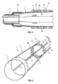
- Fig. 2 shows an enlarged cross sectional view of a distal part of a catheter comprising the device for preventing stent movement according to the present invention in an inflated state of a balloon 29.
- both a first securement connector 2 at the proximal end of the balloon 29 and a second securement connector 2 at the distal end of the balloon are employed to fix the stent 18 each using connecting members 4 - 7. Due to this cross sectional view only the connecting members 5, 7 are visible whilst the other connecting members 4, 8 are not visible.
- the securement connector 2 of each device 1 is connected with the catheter 3 via a shrink tube 31, respectively.
- the connecting members 4 - 7 are flexible and expand with the balloon 29 via their serpentine bands 24 - 26 as illustrated in the inflated state of the balloon 29 in Fig. 2 .
- the locking members 15, 16, 17 formed at the second end portions 8 - 11 of the connecting members 4 - 7 respectively, comprise the form of a clasp section snapping, as shown in Fig. 2 e. g. into one gap 22 of gaps 22, 23 between two adjacent struts 20, 21 of said struts 19 - 21 of the stent 18 being identified by reference signs representative for all struts and gaps of the stent.
- the stent 18 is fixed from the proximal end as well as the distal end via the device1, respectively and reliably prevented from moving.
- Fig. 3 shows an enlarged cross sectional view of stent delivery system 30 according to the present invention comprising the catheter 3, the expandable balloon 29 and the radially expandable stent 18 in a deflated state of the balloon 29.
- the flexible connecting members 4 - 7 which are formed from a shape memory material (or other flexible material like nitinol or elastic polymer) bend back and retain their generally linear shape, as shown in Fig. 1 , wherein the locking members 15 - 17 on their second end portions 12 - 14 remaining engaged within respective gaps 22, 23 between the struts 19 - 21 of the stent 18.
- Fig. 3 the same connecting configuration as in Fig.
- Fig. 4 shows an enlarged perspective view of a further embodiment of the device for preventing stent movement according to the present invention.
- highly flexible prongs 27, 28 are provided to connect the connecting members 4 - 7 in a region adjacent to their second end portion 12 - 14 for a further improved fixation of a non-modified stent 18.
Landscapes
- Health & Medical Sciences (AREA)
- Engineering & Computer Science (AREA)
- Biomedical Technology (AREA)
- Cardiology (AREA)
- Oral & Maxillofacial Surgery (AREA)
- Transplantation (AREA)
- Heart & Thoracic Surgery (AREA)
- Vascular Medicine (AREA)
- Life Sciences & Earth Sciences (AREA)
- Animal Behavior & Ethology (AREA)
- General Health & Medical Sciences (AREA)
- Public Health (AREA)
- Veterinary Medicine (AREA)
- Media Introduction/Drainage Providing Device (AREA)
Abstract
Description
- The present invention relates to a device for preventing stent movement during delivery into a lumen of a body vessel and a stent delivery system.
- A mechanism to improve stent securement is known from
US 2004/0236406 A1 . This device comprises a securement connector arranged to engage a catheter, at least a flexible connecting member coupled to the securement connector and a locking member arranged to engage a portion of a stent. For the engagement of the locking member with the stent, however, an associated engagable portion formed on at least one end of the stent has to be provided. Thus said device is only usable with a modified type of stent. - It is, therefore, an object of the present invention to provide a device for preventing stent movement that can be used without additional engagable portions on the stent to be provided, and, therefore, simplifies the overall connecting structure to prevent a stent movement.
- The solution of this object is achieved by the features of
claim - As a further aspect of the invention a stent delivery system is disclosed comprising a catheter, an expandable balloon and a radially expandable stent having at least one engagable portion which is characterized by a device for preventing stent movement according to the present invention, which comprises a securement connector arranged to engage a catheter and at least one flexible connecting member. Said flexible connecting member has a first portion and a second portion, the first portion being coupled to said securement connector. Further said device for preventing stent movement comprises a locking member located at said flexible connecting member second end portion. This locking member is arranged to engage a portion of a stent comprising struts defining gaps therebetween wherein said locking member takes the form of a clasp section snapping into one gap of said gaps between the struts. So, as a specific advantage, a standard type stent without any modifications can be secured by simply using the gaps of the stent structure as the technical feature cooperating with the clasp section of the locking member.
- The dependent claims contain advantageous embodiments of the present invention.
- A method of assembling a device for preventing movement of a stent is defined in
claim 12 comprising the following method steps: mounting the stent in a pre-crimped state over the balloon working length of a balloon; positioning the stent over clasp sections of locking members of the device for preventing stent movement during delivery ensuring that the clasp sections are aligned between the struts of the stent; inserting the entire assembly of the stent and the preventing device into a crimp head of a crimping device crimped in the entire assembly to its nominal diameter. - Further features and advantages of the present invention will become apparent from the following description of preferred embodiments with reference to the appended drawings, wherein
-
Fig. 1 shows an enlarged perspective view of the device for preventing stent movement according to the present invention, -
Fig. 2 shows an enlarged cross sectional view of a distal part of a catheter comprising the device for preventing stent movement according to the present invention in an inflated state of the balloon, -
Fig. 3 shows an enlarged cross sectional view of a stent delivery system according to the present invention in a deflated state of the balloon, and -
Fig. 4 shows an enlarged perspective view of a further embodiment of the device for preventing stent movement according to the present invention. - In the perspective view of
Fig. 1 thedevice 1 for preventing stent movement is depicted. Thedevice 1 comprises on its proximal end asecurement connector 2 in the form of a ring to be connected with acatheter 3. A plurality of flexible connectingmembers first end portions connector 2 and extend in a distal direction viaserpentine bands second end portions device 1. Thesecond end portions locking members stent 18 not shown inFig. 1 . -
Fig. 2 shows an enlarged cross sectional view of a distal part of a catheter comprising the device for preventing stent movement according to the present invention in an inflated state of aballoon 29. As can be seen fromFig. 2 , both afirst securement connector 2 at the proximal end of theballoon 29 and asecond securement connector 2 at the distal end of the balloon are employed to fix thestent 18 each using connecting members 4 - 7. Due to this cross sectional view only the connectingmembers members securement connector 2 of eachdevice 1 is connected with thecatheter 3 via ashrink tube 31, respectively. The connecting members 4 - 7 are flexible and expand with theballoon 29 via their serpentine bands 24 - 26 as illustrated in the inflated state of theballoon 29 inFig. 2 . Thelocking members Fig. 2 e. g. into onegap 22 ofgaps adjacent struts stent 18 being identified by reference signs representative for all struts and gaps of the stent. Thus, without the need of modifications of the stent structure thestent 18 is fixed from the proximal end as well as the distal end via the device1, respectively and reliably prevented from moving. -
Fig. 3 shows an enlarged cross sectional view ofstent delivery system 30 according to the present invention comprising thecatheter 3, theexpandable balloon 29 and the radiallyexpandable stent 18 in a deflated state of theballoon 29. When theballoon 29 is deflated the flexible connecting members 4 - 7 which are formed from a shape memory material (or other flexible material like nitinol or elastic polymer) bend back and retain their generally linear shape, as shown inFig. 1 , wherein the locking members 15 - 17 on their second end portions 12 - 14 remaining engaged withinrespective gaps stent 18. InFig. 3 the same connecting configuration as inFig. 1 is exemplarily depicted with the two connectingmembers gap 22 between thestruts stent 18. However, upon retraction ofcatheter 3 the locking members 15 - 17 easily slide out of therespective gaps 22 in order to releasestent 18. -
Fig. 4 shows an enlarged perspective view of a further embodiment of the device for preventing stent movement according to the present invention. In this embodiment highlyflexible prongs stent 18. - In addition to the written disclosure reference is herewith made explicitly to the disclosure of the invention in
Fig. 1 to 4 . -
- 1
- device for preventing stent movement
- 2
- securement connector
- 3
- catheter
- 4,5,6,7
- connecting member
- 8,9,10,11
- first end portion
- 12,13,14
- second end portion
- 15,16,17
- locking member
- 18
- stent
- 19,20,21
- struts
- 22,23
- gaps, engagable portions
- 24,25,26
- serpentine band
- 27,28
- prongs
- 29
- balloon
- 30
- stent delivery system
- 31
- shrink tube
Claims (12)
- A device (1) for preventing stent movement during delivery comprising:- a securement connector (2) arranged to engage a catheter (3) ;- at least one flexible connecting member (4 - 7), said flexible connecting member (4 - 7) having a first end portion (8 - 11) and a second end portion (12 - 14), the first end portion (8 - 11) coupled to said securement connector (2), and- a locking member (15 - 17) located at said flexible connecting member second end portion (12 - 14) arranged to engage a portion of a stent (18) comprising struts (19 - 21) defining gaps (22, 23) therebetween;wherein said locking member (15 - 17) takes the form of a clasp section snapping into one gap (22) of said gaps (22, 23) between the struts (19 - 21).
- The device of claim 1 comprising a plurality of flexible connecting members (4 - 7).
- The device of claim 1 or 2 wherein said flexible connecting member (4 - 7) is adapted to expand with the stent (18).
- The device of one of claims 1 to 3, wherein each connecting member (4 - 7) comprises a serpentine band (24, 25, 26) being disposed between the first end portion (8 - 11) and the locking member (15 - 17).
- The device of one of claims 1 to 4, wherein the flexible connecting member (4 - 7) is balloon expandable.
- The device of one of claims 1 to 5, wherein the flexible connecting member (4 - 7) is made from a shape memory material.
- The device of claim 6, wherein the shape memory material has an Af temperature lower than the normal human body temperature.
- The device according to one of claims 1 to 7, wherein a shrink tube (31) connects the securement connector (2) with the stent (18)
- The device according to one of claims 1 to 8, wherein prongs (27, 28) connect the connecting members (4 - 7) in a region adjacent to their second end portion (12 - 14)
- A stent delivery system (30) comprising:a catheter (3);an expandable balloon (29), anda radially expandable stent (18) having at least one engagable portion (22) characterized by a device (1) according to one of claims 1 - 8.
- The stent delivery system of claim 10 wherein said device (1) and said stent engagable portion (22) are adapted to remain engaged until said balloon (29) is deflated.
- Method of assembling a device (1) for preventing movement of a stent during stent delivery, said stent including a stent body having struts (19 - 21) comprising:mounting the stent (18) in a pre-crimped state over the balloon working length of a balloon (29);positioning the stent (18) over clasp sections of the locking members (15, 16, 17) of the device (1) for preventing stent movement during delivery ensuring that the clasp sections are aligned between the struts (19 - 21) of the stent (18);inserting the entire assembly of the stent (18) and the preventing device (1) into a crimp head of a crimping device in which the entire assembly is crimped to its nominal diameter.
Priority Applications (3)
| Application Number | Priority Date | Filing Date | Title |
|---|---|---|---|
| EP08013292A EP2147663A1 (en) | 2008-07-23 | 2008-07-23 | Stent movement preventing device |
| PCT/EP2009/003525 WO2010009782A1 (en) | 2008-07-23 | 2009-05-18 | Stent movement preventing device |
| US13/055,292 US20120095544A1 (en) | 2008-07-23 | 2009-05-18 | Stent movement preventing device |
Applications Claiming Priority (1)
| Application Number | Priority Date | Filing Date | Title |
|---|---|---|---|
| EP08013292A EP2147663A1 (en) | 2008-07-23 | 2008-07-23 | Stent movement preventing device |
Publications (1)
| Publication Number | Publication Date |
|---|---|
| EP2147663A1 true EP2147663A1 (en) | 2010-01-27 |
Family
ID=39885212
Family Applications (1)
| Application Number | Title | Priority Date | Filing Date |
|---|---|---|---|
| EP08013292A Withdrawn EP2147663A1 (en) | 2008-07-23 | 2008-07-23 | Stent movement preventing device |
Country Status (3)
| Country | Link |
|---|---|
| US (1) | US20120095544A1 (en) |
| EP (1) | EP2147663A1 (en) |
| WO (1) | WO2010009782A1 (en) |
Families Citing this family (1)
| Publication number | Priority date | Publication date | Assignee | Title |
|---|---|---|---|---|
| WO2013003450A1 (en) * | 2011-06-27 | 2013-01-03 | Boston Scientific Scimed, Inc. | Stent delivery systems and methods for making and using stent delivery systems |
Citations (8)
| Publication number | Priority date | Publication date | Assignee | Title |
|---|---|---|---|---|
| WO2000071059A1 (en) * | 1999-05-20 | 2000-11-30 | Boston Scientific Limited | Stent delivery system for prevention of kinking, and method of loading and using same |
| US6168616B1 (en) * | 1997-06-02 | 2001-01-02 | Global Vascular Concepts | Manually expandable stent |
| US20020161377A1 (en) * | 2001-04-27 | 2002-10-31 | Dmitry Rabkin | Apparatus for delivering, repositioning and/or retrieving self-expanding stents |
| US6776791B1 (en) * | 1998-04-01 | 2004-08-17 | Endovascular Technologies, Inc. | Stent and method and device for packing of same |
| US20040236406A1 (en) | 2003-05-20 | 2004-11-25 | Scimed Life Systems, Inc. | Mechanism to improve stent securement |
| US20060288561A1 (en) * | 2005-06-27 | 2006-12-28 | Boston Scientific Scimed, Inc. | Crimping and edge protection elements |
| WO2007109621A2 (en) * | 2006-03-20 | 2007-09-27 | Xtent, Inc. | Apparatus and methods for deployment of linked prosthetic segments |
| WO2008039283A1 (en) * | 2006-09-25 | 2008-04-03 | Boston Scientific Limited | Balloon with wings for rotational stent |
Family Cites Families (3)
| Publication number | Priority date | Publication date | Assignee | Title |
|---|---|---|---|---|
| US8353945B2 (en) * | 2001-12-03 | 2013-01-15 | J.W. Medical System Ltd. | Delivery catheter having active engagement mechanism for prosthesis |
| US7771463B2 (en) * | 2003-03-26 | 2010-08-10 | Ton Dai T | Twist-down implant delivery technologies |
| EP1988851A2 (en) * | 2006-02-14 | 2008-11-12 | Sadra Medical, Inc. | Systems and methods for delivering a medical implant |
-
2008
- 2008-07-23 EP EP08013292A patent/EP2147663A1/en not_active Withdrawn
-
2009
- 2009-05-18 WO PCT/EP2009/003525 patent/WO2010009782A1/en active Application Filing
- 2009-05-18 US US13/055,292 patent/US20120095544A1/en not_active Abandoned
Patent Citations (8)
| Publication number | Priority date | Publication date | Assignee | Title |
|---|---|---|---|---|
| US6168616B1 (en) * | 1997-06-02 | 2001-01-02 | Global Vascular Concepts | Manually expandable stent |
| US6776791B1 (en) * | 1998-04-01 | 2004-08-17 | Endovascular Technologies, Inc. | Stent and method and device for packing of same |
| WO2000071059A1 (en) * | 1999-05-20 | 2000-11-30 | Boston Scientific Limited | Stent delivery system for prevention of kinking, and method of loading and using same |
| US20020161377A1 (en) * | 2001-04-27 | 2002-10-31 | Dmitry Rabkin | Apparatus for delivering, repositioning and/or retrieving self-expanding stents |
| US20040236406A1 (en) | 2003-05-20 | 2004-11-25 | Scimed Life Systems, Inc. | Mechanism to improve stent securement |
| US20060288561A1 (en) * | 2005-06-27 | 2006-12-28 | Boston Scientific Scimed, Inc. | Crimping and edge protection elements |
| WO2007109621A2 (en) * | 2006-03-20 | 2007-09-27 | Xtent, Inc. | Apparatus and methods for deployment of linked prosthetic segments |
| WO2008039283A1 (en) * | 2006-09-25 | 2008-04-03 | Boston Scientific Limited | Balloon with wings for rotational stent |
Also Published As
| Publication number | Publication date |
|---|---|
| WO2010009782A1 (en) | 2010-01-28 |
| US20120095544A1 (en) | 2012-04-19 |
Similar Documents
| Publication | Publication Date | Title |
|---|---|---|
| CN108186176B (en) | Implant delivery system | |
| US9005265B2 (en) | Stent having radially expandable main body | |
| US8876879B2 (en) | Introducer | |
| US8652196B2 (en) | Stent | |
| ES2932656T3 (en) | Distal Capture Device for a Self Expanding Stent Graft | |
| US20040015229A1 (en) | Vascular stent with radiopaque markers | |
| US20070293935A1 (en) | Stent deployment anchoring device | |
| US10932932B2 (en) | Delivery device with an expandable positioner for positioning a prosthesis | |
| CN109248012B (en) | Implant delivery system | |
| CN107438418B (en) | Airway stent | |
| CA2636561A1 (en) | An axially-elongating stent and method of deployment | |
| EP2147696B1 (en) | Balloon catheter | |
| EP2147663A1 (en) | Stent movement preventing device | |
| US20220370253A1 (en) | A tympanostomy tube | |
| US10441289B2 (en) | Airway valve with anchors | |
| US20190021886A1 (en) | Segmented self-expanding stent | |
| EP3562444B1 (en) | A stent for implant within a vein | |
| EP4099921B1 (en) | Embolisation system for promoting clot formation | |
| EP2489337A1 (en) | Prosthesis and method of manufacture | |
| KR200246731Y1 (en) | Position maintaining device of lumen expansion stent | |
| US20240058013A1 (en) | Embolisation System for Promoting Blood Clot Formation | |
| US20240091036A1 (en) | A stent for implant within a vessel | |
| EP4322866A1 (en) | Embolisation system for promoting clot formation |
Legal Events
| Date | Code | Title | Description |
|---|---|---|---|
| PUAI | Public reference made under article 153(3) epc to a published international application that has entered the european phase |
Free format text: ORIGINAL CODE: 0009012 |
|
| AK | Designated contracting states |
Kind code of ref document: A1 Designated state(s): AT BE BG CH CY CZ DE DK EE ES FI FR GB GR HR HU IE IS IT LI LT LU LV MC MT NL NO PL PT RO SE SI SK TR |
|
| AX | Request for extension of the european patent |
Extension state: AL BA MK RS |
|
| 17P | Request for examination filed |
Effective date: 20100312 |
|
| 17Q | First examination report despatched |
Effective date: 20100423 |
|
| AKX | Designation fees paid |
Designated state(s): AT BE BG CH CY CZ DE DK EE ES FI FR GB GR HR HU IE IS IT LI LT LU LV MC MT NL NO PL PT RO SE SI SK TR |
|
| STAA | Information on the status of an ep patent application or granted ep patent |
Free format text: STATUS: THE APPLICATION IS DEEMED TO BE WITHDRAWN |
|
| 18D | Application deemed to be withdrawn |
Effective date: 20130319 |