EP2127945A2 - Method and device for controlling the light emission of a vehicle - Google Patents
Method and device for controlling the light emission of a vehicle Download PDFInfo
- Publication number
- EP2127945A2 EP2127945A2 EP09161344A EP09161344A EP2127945A2 EP 2127945 A2 EP2127945 A2 EP 2127945A2 EP 09161344 A EP09161344 A EP 09161344A EP 09161344 A EP09161344 A EP 09161344A EP 2127945 A2 EP2127945 A2 EP 2127945A2
- Authority
- EP
- European Patent Office
- Prior art keywords
- vehicle
- traffic situation
- situation type
- objects
- detected
- Prior art date
- Legal status (The legal status is an assumption and is not a legal conclusion. Google has not performed a legal analysis and makes no representation as to the accuracy of the status listed.)
- Granted
Links
Images
Classifications
-
- B—PERFORMING OPERATIONS; TRANSPORTING
- B60—VEHICLES IN GENERAL
- B60Q—ARRANGEMENT OF SIGNALLING OR LIGHTING DEVICES, THE MOUNTING OR SUPPORTING THEREOF OR CIRCUITS THEREFOR, FOR VEHICLES IN GENERAL
- B60Q1/00—Arrangement of optical signalling or lighting devices, the mounting or supporting thereof or circuits therefor
- B60Q1/02—Arrangement of optical signalling or lighting devices, the mounting or supporting thereof or circuits therefor the devices being primarily intended to illuminate the way ahead or to illuminate other areas of way or environments
- B60Q1/04—Arrangement of optical signalling or lighting devices, the mounting or supporting thereof or circuits therefor the devices being primarily intended to illuminate the way ahead or to illuminate other areas of way or environments the devices being headlights
- B60Q1/06—Arrangement of optical signalling or lighting devices, the mounting or supporting thereof or circuits therefor the devices being primarily intended to illuminate the way ahead or to illuminate other areas of way or environments the devices being headlights adjustable, e.g. remotely-controlled from inside vehicle
- B60Q1/08—Arrangement of optical signalling or lighting devices, the mounting or supporting thereof or circuits therefor the devices being primarily intended to illuminate the way ahead or to illuminate other areas of way or environments the devices being headlights adjustable, e.g. remotely-controlled from inside vehicle automatically
- B60Q1/085—Arrangement of optical signalling or lighting devices, the mounting or supporting thereof or circuits therefor the devices being primarily intended to illuminate the way ahead or to illuminate other areas of way or environments the devices being headlights adjustable, e.g. remotely-controlled from inside vehicle automatically due to special conditions, e.g. adverse weather, type of road, badly illuminated road signs or potential dangers
-
- G—PHYSICS
- G06—COMPUTING; CALCULATING OR COUNTING
- G06V—IMAGE OR VIDEO RECOGNITION OR UNDERSTANDING
- G06V20/00—Scenes; Scene-specific elements
- G06V20/50—Context or environment of the image
- G06V20/56—Context or environment of the image exterior to a vehicle by using sensors mounted on the vehicle
- G06V20/58—Recognition of moving objects or obstacles, e.g. vehicles or pedestrians; Recognition of traffic objects, e.g. traffic signs, traffic lights or roads
- G06V20/584—Recognition of moving objects or obstacles, e.g. vehicles or pedestrians; Recognition of traffic objects, e.g. traffic signs, traffic lights or roads of vehicle lights or traffic lights
-
- B—PERFORMING OPERATIONS; TRANSPORTING
- B60—VEHICLES IN GENERAL
- B60Q—ARRANGEMENT OF SIGNALLING OR LIGHTING DEVICES, THE MOUNTING OR SUPPORTING THEREOF OR CIRCUITS THEREFOR, FOR VEHICLES IN GENERAL
- B60Q2300/00—Indexing codes for automatically adjustable headlamps or automatically dimmable headlamps
- B60Q2300/40—Indexing codes relating to other road users or special conditions
- B60Q2300/41—Indexing codes relating to other road users or special conditions preceding vehicle
-
- B—PERFORMING OPERATIONS; TRANSPORTING
- B60—VEHICLES IN GENERAL
- B60Q—ARRANGEMENT OF SIGNALLING OR LIGHTING DEVICES, THE MOUNTING OR SUPPORTING THEREOF OR CIRCUITS THEREFOR, FOR VEHICLES IN GENERAL
- B60Q2300/00—Indexing codes for automatically adjustable headlamps or automatically dimmable headlamps
- B60Q2300/40—Indexing codes relating to other road users or special conditions
- B60Q2300/42—Indexing codes relating to other road users or special conditions oncoming vehicle
-
- B—PERFORMING OPERATIONS; TRANSPORTING
- B60—VEHICLES IN GENERAL
- B60Q—ARRANGEMENT OF SIGNALLING OR LIGHTING DEVICES, THE MOUNTING OR SUPPORTING THEREOF OR CIRCUITS THEREFOR, FOR VEHICLES IN GENERAL
- B60Q2300/00—Indexing codes for automatically adjustable headlamps or automatically dimmable headlamps
- B60Q2300/40—Indexing codes relating to other road users or special conditions
- B60Q2300/45—Special conditions, e.g. pedestrians, road signs or potential dangers
Definitions
- the invention relates to a method and a device for controlling the light output of a vehicle.
- Such a system for distance measurement is known for example from the German patent application DE 10 2007 021 576 known. From the document DE 10 2006 001 033 A1 Furthermore, an apparatus and a method for recognizing an object are known with which an object identity assignment of objects detected in an image is possible.
- Markers can be quickly and reliably identified even when blurred by an image acquisition system on an image sensor or when these objects are partially hidden. Furthermore, the position of these objects can be determined.
- a camera-based position detection for a road vehicle is known in which the lying in the direction of travel of the vehicle environment is detected by means of a camera.
- the image data generated by the camera are processed. It can be concluded by means of a pattern recognition method on the position of the vehicle.
- relevant objects when relevant objects are temporarily obscured by other objects, the relevant objects are present only in some of the images sequentially taken as a sequence of images, so that both problems in detecting and classifying these objects as well as in the selection of a suitable control of the headlights of the vehicle occur.
- relevant objects are in particular preceding and oncoming vehicles of other road users. A disability of these road users by a wrong light control is to be avoided, however, so as not to hinder them and not endanger the traffic.
- the object of the invention is to provide a method and a device for controlling the light output of a vehicle, in which a disability of other road users is avoided.
- a method and by a device for controlling the light output of a vehicle is achieved that not only individual objects detected in the image in the control of the light output of a headlight of the vehicle be considered but that additionally or alternatively, a classified traffic situation type in the selection and / or determination of the light output of the headlamp of the vehicle is taken into account. As a result, errors that may occur in the classification of individual objects, detected and resulting mismanagement of the headlamps of the vehicle can be avoided.
- At least one object detected in an image recorded with the aid of a front camera of the vehicle is used as the input variable for classifying the traffic situation type.
- a plurality of objects detected in the recorded image and / or their classified object types and / or object properties of the detected objects are used as input variables for classifying the traffic situation type.
- parameters of the detected objects in particular the object classes determined for the objects, the three-dimensional position of the objects, the three-dimensional direction of movement of the objects, the speed of the objects and / or the duration of the observation of the objects in one with the aid of the front camera Vehicle detected image sequence to use as input to classify the traffic situation type.
- the traffic situation parameters of the vehicle in particular the vehicle's own speed, the three-dimensional direction of movement of the vehicle, the three-dimensional position of the vehicle, the speed of the vehicle, the inclination of the vehicle and / or the steering angle of the vehicle, as input to classify the Traffic situation type are used.
- the determined traffic situation type is used, for example, for a decision process for light control, the result of which is preferably supplied to the control modules of the headlights, for example via a bus system of the vehicle, which then depending on the result of the decision process, the actuators for adjusting the light distribution of the emitted from the headlights light radiation and / or activates or activates and / or deactivates the light sources of the front headlamps depending on the setting options and control options of the specific headlamps present in the vehicle.
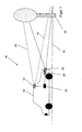
- FIG. 2 illustrates a traffic situation according to a first embodiment of the invention, in which a vehicle 12 is shown traveling along the roadway course of a roadway 14.
- the vehicle 12 has a front camera 16, which captures an image sequence with images of a detection area in front of the vehicle 12.
- the detection area is in FIG. 1 bounded by the dashed lines 18, 20.
- images with images of objects present in the detection area are thus detected, which are transmitted as image data from the front camera 16 to a processing unit 22 arranged in the vehicle 12.
- a processing unit 22 arranged in the vehicle 12.
- With the help of the front camera 16 are in the detection area in front of the vehicle 12 existing objects, such as in FIG. 1 shown laterally of the roadway 14 arranged road sign 28 detected.
- the image data of the object 28 is then processed by the processing unit 22, wherein the image of the object 28 is detected and classified as an object.
- vehicles approaching the road 14 and objects approaching on an oncoming carriageway of the road 14 are detected as objects and classified by means of the processing unit 22 as objects.
- the traffic situation by a thereto in the processing unit 22 implemented algorithm, in which the vehicle is located, and a determined by the algorithm traffic situation type in the selection and / or determination of the generated using the at least one headlight 26 light distribution in front of the vehicle 12 taken into account.
- Information about the selected or defined light distribution is transmitted by the processing unit 22 to a light control module 24 that generates a light distribution corresponding to the transmitted information depending on the available specific settings of the headlights 26 by a corresponding control of the headlights 26.
- the front camera 16 is preferably a stereo camera, with which the distance of an object to the stereo camera and thus the position of detected objects in a vehicle coordinate system, such as the traffic sign 28, can be determined.
- Object parameters can be determined for the detected objects.
- Such object parameters may be an object class determined for the respective object, the three-dimensional position of the object, the three-dimensional direction of movement of the object, the speed of the object and / or the duration of the observation of the object in an image sequence acquired with the aid of the front camera 16 of the vehicle 12.
- object parameters can be used as input variables for classifying the traffic situation type by the processing unit 22.
- the intrinsic speed of the vehicle 12, the three-dimensional movement direction of the vehicle 12, the three-dimensional position of the vehicle 12, the speed of the vehicle 12, the inclination of the vehicle 12 and / or the steering angle of the vehicle 12 can be used as input variables for classifying the traffic situation type.
- the traffic situation type determined by the processing unit 22 is then preferably used as input for a decision process for light control.
- the traffic situation type can be determined at regular intervals, preferably continuously.
- the traffic situation type can be determined again after each image or image pair of a stereo camera taken with the aid of the front camera 16 or, alternatively, can be determined regularly again after a preset number of recorded or processed images or after a preset time interval.
- a more sound definition of the maximum possible light distribution or the maximum possible illumination of the area in front of the vehicle 12 by means of the headlight 26 is possible.
- the light distribution is thereby determined not only as a function of individual detected objects but also taking into account a traffic situation or a traffic situation type.
- the light sources of vehicles are taken into account for determining the light emission and light distribution effected by means of the headlights 26 as relevant objects, that is to say, as shown in FIG. H. only light sources that have been classified as headlights or taillights of other vehicles.
- Non-relevant light sources and other non-relevant objects such as traffic signs and reflectors of guide posts, are not taken into account in determining the light distribution of the headlamps 26 in the prior art.
- the light distribution is then controlled in the prior art as a function of determined relevant objects which have been detected in a plurality of successively recorded images of an image sequence with the aid of the front camera of the vehicle.
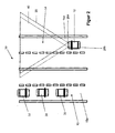
- FIG. 2 is a schematic representation of a second traffic situation 30 shown, in which a total of four vehicles 12, 32, 34, 36 are located on a four-lane road. Elements with the same structure and / or the same function are identified by the same reference numerals.
- the vehicle 12 is located on a first lane 14a of the roadway 14.
- Three oncoming traffic Vehicles 32 to 36 are located on a lane 15 a of the oncoming lane 15.
- images of the oncoming vehicles 32 to 36 detected as objects have been detected in the images of an image sequence recorded with the aid of the front camera 16 of the vehicle 12, so that these objects are detected continuously and in the light distribution generated by the headlights 26 a, 26 b of the vehicle 12 can be considered.
- the headlights 26a, 26b are controlled by light control modules 24a, 24b in accordance with the light distribution predetermined by the processing unit 22 so that the oncoming vehicles 32 to 36 are not dazzled.
- the radiation area of the light radiation radiated from the headlight 26a is schematically shown by the area delimited by the dashed line 38 and the radiation area of the light emitted by the headlight 26b is schematically indicated by the area bounded by the solid line 40.
- the processing unit 22 has set a low beam light distribution of the headlights 26a, 26b, by which the vehicles 32 to 36 can not be blinded.
- the angle of inclination and / or the lateral radiation angle can be changed.
- screens or diaphragm rollers possible to change the distribution of the radiated from the headlights 26 a, 26 b light radiation and adjust.
- Such diaphragm rollers are marketed, for example, under the trademark VarioX of the Applicant, in which currently up to five different light distributions, in particular different light distributions of the low beam, are adjustable. In particular, a special highway light, high beam As well as switching from right to left traffic using such a diaphragm roller can be easily realized. Furthermore, by appropriate design of the optics which can be provided by the diaphragm roller, other light distributions adapted to specific traffic situations can be realized. Systems with such control and design of headlamps are also referred to as variable intelligent lighting systems.
- headlamps with diaphragm rollers can also include actuators for controlling a dynamic cornering light as well as for headlamp leveling so that a multiplicity of different light distributions of the light radiation emitted by the headlamps 26a, 26b can be generated.
- LED arrays as light sources for the headlights 26a, 26b
- additional and alternative control options result, since individual LED elements of the LED array can be switched on and off. As a result, a multiplicity of different light emissions through the headlights 26a, 26b of the vehicle 12 are possible.
- headlamps with LED arrays can also be combined as light sources with actuators for changing the emission angle, in particular for changing the inclination angle and the lateral emission angle.
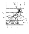
- FIG. 3 a traffic situation 50 is shown, in which a plurality of bushes 52 to 56 are arranged between the roadways 14, which temporarily cover the front headlights of the vehicles 32 to 36 to be detected as relevant objects in individual individual images taken with the aid of the front camera 16 these relevant objects can be detected only in some images of the captured with the help of the front camera 16 image sequence.
- the headlights of the vehicles 32, 34 are not detected by the processing unit 22 because these headlights are currently obscured by the bush 54 and are not present as images in the images captured by the front camera 16.
- the high beam of the vehicle 12 can be activated by the processing unit 22 in conjunction with the light control modules 24a, 24b.
- the drivers of the vehicles 32, 34 can be subsequently blinded when the light rays pass through the gaps between the bushes 52 to 56 to the vehicles 32, 34.
- an altered cut-off point beyond the range of the cut-off line of the dipped beam may result in impairment to the drivers of the oncoming vehicles 32-36 if this light is present in the areas between the objects 52-35 56 penetrates to the drivers of vehicles 32 to 36 and obstructs them.
- the visual beams 58a to 58d of the front camera 16 which are aligned with the headlights of the vehicles 32, 34, interrupted by the bush 54.
- the light beams 60a to 60d radiated from the headlights of the vehicles 32, 34 have been reflected and / or absorbed toward the front camera 16 through the bush 54 so that they do not penetrate to the front camera 16 and the headlights of the vehicles 32, 34 are not objects can be detected.
- the headlights 26a, 26b of the vehicle 12 are thereby switched to high beam, as currently no objects can be detected, which would be obstructed by the high beam.
- the drivers of the vehicles 32 to 36 are blinded by the light passing through the gaps between the bushes 52 to 56 when this light of the headlights 26 of the vehicle 12 in a further driving movement of the vehicles 12, 32 to 36, through the gaps on one of the vehicles 32 to 36 impinges.
- FIG. 3 are the Lichtabstrahl Schemee 38 ', 40' of the headlights 26a, 26b shown with activated high beam.
- traffic situation 50 is based on the activated high beam a danger of obstruction of the driver 32 to 36 from.
- the invention is based on the knowledge to classify at least problematic traffic situations by traffic situation types and to set the light distribution of the headlights 26a, 26b to be set depending on a recognized classified traffic situation type and not or not solely dependent on the presence of individual relevant objects.
- different parameters of the objects are used to classify the traffic situation type.
- the classified object types of detected objects such as headlights, taillights, power lights, etc.
- the estimated three-dimensional position of the objects detected in the images of the front camera 16 the three-dimensional direction vector of the detected objects, the speed of the detected objects, and / or the duration the observation of the detected objects in a plurality of sequentially recorded by means of the front camera 16 images.
- the objects can be tracked over a plurality of images of a sequence of images recorded with the aid of the front camera with the aid of a known tracking method.
- vehicle data of the vehicle 12 can be used, that of the processing unit 22, in particular via a CAN bus system of the vehicle 12, from others Unillustrated control units of the vehicle 12 are provided. These vehicle data are, in particular, the speed of the vehicle 12, the steering wheel angle of the vehicle 12, the course of the speed and / or the course of the steering angle of the vehicle 12.
- the following table shows the object parameters determined by the processing unit 22, the traffic situation type classified on the basis of these object parameters, and Reaction of the light system for various exemplary traffic situations listed.
- both the determined object parameters which lead to the classification of the respective traffic situation type as well as the listed traffic situation types and the reaction of the light system are related only to one specific exemplary embodiment and the traffic situation types, the parameters leading to the classification of a traffic situation type and Reaction of the lighting system may differ in other embodiments.
- determined object parameters of detected objects Classified traffic situation type Reaction of the lighting system Determined object position: behind the own vehicle; Direction of movement Object: opposite; determined object class: headlights oncoming object has passed, no further relevant objects detected fast activation of the high beam Object position: close; determined object class: tail lights; Direction of movement Object: forward Object overhauls own vehicle High beam off, disabling vertical cut-off control on the side where the object overtakes its own vehicle Airspeed: high; Rate detected opposite and with lateral offset to the direction of movement of the vehicle's own moving objects: high Highway low increase in headlamp level with respect to low beam by removing the cut-off line Airspeed medium; Distance to the guide post row left / right: close; lateral displacement of passing vehicles> 5m country road no restrictions if no other vehicles are detected, vertical cut-off can be activated for both headlights Number of objects classified as network lamps: high; Airspeed: low city Deactivation of the high beam assistant, no raising of the cut-off limit permitted; Deactivation of the vertical cut-off control Number
Landscapes
- Engineering & Computer Science (AREA)
- Mechanical Engineering (AREA)
- Physics & Mathematics (AREA)
- General Physics & Mathematics (AREA)
- Multimedia (AREA)
- Theoretical Computer Science (AREA)
- Lighting Device Outwards From Vehicle And Optical Signal (AREA)
- Traffic Control Systems (AREA)
Abstract
Description
Die Erfindung betrifft ein Verfahren und eine Vorrichtung zum Steuern der Lichtabgabe eines Fahrzeugs.The invention relates to a method and a device for controlling the light output of a vehicle.
Aus den Dokumenten
Aus dem Dokument
Aus dem Dokument
Aus dem Dokument
Aus dem Dokument
Aus dem Dokument
Um Beeinträchtigungen anderer Verkehrsteilnehmer zu vermieden, müssen Lichtquellen in einer Szene erkannt und als relevant oder nicht relevant klassifiziert werden. Die Lichtsteuerung der Frontscheinwerfer eines Fahrzeugs erfolgt dann unter Berücksichtigung der Position der relevanten Lichtquellen. Diese Funktionalität reicht jedoch in verschiedenen Verkehrssituationen nicht für eine fehlerfreie Lichtabgabe durch die Frontscheinwerfer des Fahrzeugs aus, um eine Behinderung anderer Fahrzeugführer sicher auszuschließen.In order to avoid impairments of other road users, light sources in a scene must be detected and classified as relevant or irrelevant become. The light control of the headlights of a vehicle is then carried out taking into account the position of the relevant light sources. However, this functionality is not sufficient in various traffic situations for a flawless light output through the headlights of the vehicle to safely exclude disability of other drivers.
Insbesondere wenn relevante Objekte, temporär von weiteren Objekten verdeckt werden, sind die relevanten Objekte nur in einigen der nacheinander als Bildfolge aufgenommenen Bildern vorhanden, sodass sowohl Probleme beim Detektieren und Klassifizieren dieser Objekte als auch bei der Auswahl einer geeigneten Ansteuerung der Frontscheinwerfer des Fahrzeugs auftreten. Solche relevanten Objekte sind insbesondere vorausfahrende und entgegenkommende Fahrzeuge anderer Verkehrsteilnehmer. Eine Behinderung dieser Verkehrsteilnehmer durch eine falsche Lichtansteuerung ist jedoch zu vermeiden, um sie nicht zu behindern und den Verkehr nicht zu gefährden.In particular, when relevant objects are temporarily obscured by other objects, the relevant objects are present only in some of the images sequentially taken as a sequence of images, so that both problems in detecting and classifying these objects as well as in the selection of a suitable control of the headlights of the vehicle occur. Such relevant objects are in particular preceding and oncoming vehicles of other road users. A disability of these road users by a wrong light control is to be avoided, however, so as not to hinder them and not endanger the traffic.
Aufgabe der Erfindung ist es, ein Verfahren und eine Vorrichtung zum Steuern der Lichtabgabe eines Fahrzeugs anzugeben, bei denen eine Behinderung anderer Verkehrsteilnehmer vermieden wird.The object of the invention is to provide a method and a device for controlling the light output of a vehicle, in which a disability of other road users is avoided.
Diese Aufgabe wird durch ein Verfahren zum Steuern der Lichtabgabe eines Fahrzeugs mit den Merkmalen des Patentanspruchs 1 sowie durch eine Vorrichtung mit den Merkmalen des nebengeordneten Vorrichtungsanspruchs gelöst. Vorteilhafte Weiterbildungen der Erfindung sind in den abhängigen Patentansprüchen angegeben.This object is achieved by a method for controlling the light output of a vehicle having the features of patent claim 1 and by a device having the features of the independent device claim. Advantageous developments of the invention are specified in the dependent claims.
Durch ein Verfahren und durch eine Vorrichtung zum Steuern der Lichtabgabe eines Fahrzeugs wird erreicht, dass nicht nur einzelne im Bild detektierte Objekte bei der Steuerung der Lichtabgabe eines Frontscheinwerfers des Fahrzeugs berücksichtigt werden sondern dass zusätzlich oder alternativ ein klassifizierter Verkehrssituationstyp bei der Auswahl und/oder Festlegung der Lichtabgabe des Frontscheinwerfers des Fahrzeugs mit berücksichtigt wird. Dadurch können Fehler, die bei der Klassifizierung einzelner Objekte auftreten können, erkannt und daraus resultierende Fehlansteuerungen der Frontscheinwerfer des Fahrzeugs vermieden werden. Somit wird eine Blendung anderer Verkehrsteilnehmer verhindert, wobei gleichzeitig eine dem klassifizierten Verkehrssituationstyp entsprechende größtmögliche Ausleuchtung des Bereichs vor dem Fahrzeug durch eine geeignete Lichtabgabe des Frontscheinwerfers erfolgt, sodass für die klassifizierte Verkehrssituation eine bestmögliche Ausleuchtung des Bereichs vor dem Fahrzeug vorzugsweise unter Berücksichtigung detektierter relevanter Objekte möglich ist.By a method and by a device for controlling the light output of a vehicle is achieved that not only individual objects detected in the image in the control of the light output of a headlight of the vehicle be considered but that additionally or alternatively, a classified traffic situation type in the selection and / or determination of the light output of the headlamp of the vehicle is taken into account. As a result, errors that may occur in the classification of individual objects, detected and resulting mismanagement of the headlamps of the vehicle can be avoided. Thus, a dazzling of other road users is prevented, at the same time corresponding to the classified traffic situation type greatest possible illumination of the area in front of the vehicle by a suitable light output of the headlamp, so for the classified traffic situation the best possible illumination of the area in front of the vehicle preferably taking into account detected relevant objects possible is.
Bei einer Weiterbildung der Erfindung wird als Eingangsgröße zur Klassifizierung des Verkehrssituationstyps mindestens ein in einem mit Hilfe einer Frontkamera des Fahrzeugs aufgenommenen Bild detektiertes Objekt genutzt. Vorzugsweise werden mehrere im aufgenommenen Bild detektierte Objekte und/oder deren klassifizierte Objekttypen und/oder Objekteigenschaften der detektierten Objekte als Eingangsgrößen zur Klassifizierung des Verkehrssituationstyps genutzt. Dabei ist es vorteilhaft, Parameter der detektierten Objekte, insbesondere die für die Objekte ermittelten Objektklassen, die dreidimensionale Position der Objekte, die dreidimensionale Bewegungsrichtung der Objekte, die Geschwindigkeit der Objekte und/oder die Dauer der Beobachtung der Objekte in einer mit Hilfe der Frontkamera des Fahrzeugs erfassten Bildfolge, als Eingangsgrößen zur Klassifizierung des Verkehrssituationstyps zu nutzen.In one development of the invention, at least one object detected in an image recorded with the aid of a front camera of the vehicle is used as the input variable for classifying the traffic situation type. Preferably, a plurality of objects detected in the recorded image and / or their classified object types and / or object properties of the detected objects are used as input variables for classifying the traffic situation type. In this case, it is advantageous to set parameters of the detected objects, in particular the object classes determined for the objects, the three-dimensional position of the objects, the three-dimensional direction of movement of the objects, the speed of the objects and / or the duration of the observation of the objects in one with the aid of the front camera Vehicle detected image sequence to use as input to classify the traffic situation type.
Bei einer weiteren vorteilhaften Weiterbildung werden zusätzlich oder alternativ auch für das Steuern der Lichtabgabe des Fahrzeugs nicht unmittelbar relevante Objekte detektiert, klassifiziert und bei der Klassifizierung der Verkehrssituation berücksichtigt, um den Verkehrssituationstyp zu bestimmen. Weiterhin ist es vorteilhaft, den Verkehrssituationstyp in regelmäßigen Abständen, vorzugsweise kontinuierlich, zu ermitteln.In a further advantageous development, additionally or alternatively, for the control of the light output of the vehicle are not directly relevant Objects are detected, classified and considered in the classification of the traffic situation to determine the type of traffic situation. Furthermore, it is advantageous to determine the traffic situation type at regular intervals, preferably continuously.
Ferner können zum Klassifizieren der Verkehrssituation Parameter des Fahrzeugs, insbesondere die Eigengeschwindigkeit des Fahrzeugs, die dreidimensionale Bewegungsrichtung des Fahrzeugs, die dreidimensionale Position des Fahrzeugs, die Geschwindigkeit des Fahrzeugs, die Neigung des Fahrzeugs und/oder der Lenkwinkel des Fahrzeugs, als Eingangsgrößen zur Klassifizierung des Verkehrssituationstyps genutzt werden.Further, to classify the traffic situation parameters of the vehicle, in particular the vehicle's own speed, the three-dimensional direction of movement of the vehicle, the three-dimensional position of the vehicle, the speed of the vehicle, the inclination of the vehicle and / or the steering angle of the vehicle, as input to classify the Traffic situation type are used.
Der ermittelte Verkehrssituationstyp wird beispielsweise für einen Entscheidungsprozess zur Lichtsteuerung genutzt, dessen Ergebnis vorzugsweise den Steuermodulen der Frontscheinwerfer beispielsweise über ein Bussystem des Fahrzeugs zugeführt wird, die dann abhängig von dem Ergebnis des Entscheidungsprozesses die Aktoren zum Einstellen der Lichtverteilung der von den Frontscheinwerfern abgegebenen Lichtstrahlung und/oder die Lichtquellen der Frontscheinwerfer abhängig von den Einstellmöglichkeiten und Steuermöglichkeiten der konkreten im Fahrzeug vorhandenen Frontscheinwerfern ansteuert bzw. aktiviert und/oder deaktiviert.The determined traffic situation type is used, for example, for a decision process for light control, the result of which is preferably supplied to the control modules of the headlights, for example via a bus system of the vehicle, which then depending on the result of the decision process, the actuators for adjusting the light distribution of the emitted from the headlights light radiation and / or activates or activates and / or deactivates the light sources of the front headlamps depending on the setting options and control options of the specific headlamps present in the vehicle.
Weitere Merkmale und Vorteile der Erfindung ergeben sich aus der folgenden Beschreibung, welche in Verbindung mit den beigefügten Figuren die Erfindung anhand eines Ausführungsbeispiels näher erläutert.Further features and advantages of the invention will become apparent from the following description which, in conjunction with the accompanying figures, the invention using an exemplary embodiment explained in more detail.
- Figur 1FIG. 1
- eine schematische Darstellung einer ersten Verkehrssituation mit einem Fahrzeug und einer seitlich der Fahrbahn angeordneten Baumbepflanzung als Seitenansicht;a schematic representation of a first traffic situation with a vehicle and a side of the roadway tree planting arranged as a side view;
- Figur 2FIG. 2
- eine schematische Darstellung einer zweiten Verkehrssituation als Draufsicht; unda schematic representation of a second traffic situation as a plan view; and
- Figur 3FIG. 3
- eine schematische Darstellung einer dritten Verkehrssituation als Draufsicht.a schematic representation of a third traffic situation as a plan view.
In
Die Frontkamera 16 ist vorzugsweise eine Stereokamera, mit der die Entfernung eines Objekts zur Stereokamera und somit die Position von erfassten Objekten in einem Fahrzeugkoordinatensystem, wie das Verkehrsschild 28, bestimmt werden kann. Für die detektierten Objekte können jeweils Objektparameter ermittelt werden. Solche Objektparameter können eine für das jeweilige Objekt ermittelte Objektklasse, die dreidimensionale Position des Objekts, die dreidimensionale Bewegungsrichtung des Objekts, die Geschwindigkeit des Objekts und/oder die Dauer der Beobachtung des Objekts in einer mit Hilfe der Frontkamera 16 des Fahrzeugs 12 erfassten Bildfolge sein. Diese Objektparameter können als Eingangsgrößen zur Klassifizierung des Verkehrssituationstyps durch die Verarbeitungseinheit 22 verwendet werden. Ferner kann die Eigengeschwindigkeit des Fahrzeugs 12, die dreidimensionale Bewegungsrichtung des Fahrzeugs 12, die dreidimensionale Position des Fahrzeugs 12, die Geschwindigkeit des Fahrzeugs 12, die Neigung des Fahrzeugs 12 und/oder der Lenkwinkel des Fahrzeugs 12 als Eingangsgrößen zur Klassifizierung des Verkehrssituationstyps genutzt werden. Der durch die Verarbeitungseinheit 22 ermittelte Verkehrssituationstyp wird dann vorzugsweise als Eingangsgröße für einen Entscheidungsprozess zur Lichtsteuerung genutzt.The
Der Verkehrssituationstyp kann in regelmäßigen Abständen, vorzugsweise kontinuierlich ermittelt werden. Dabei kann der Verkehrssituationstyp nach jedem mit Hilfe der Frontkamera 16 aufgenommenen Bild bzw. Bildpaar einer Stereokamera erneut ermittelt werden oder alternativ nach einer voreingestellten Anzahl aufgenommener oder verarbeiteter Bilder oder nach einem voreingestellten Zeitintervall regelmäßig erneut ermittelt werden. Dadurch ist eine fundiertere Festlegung der maximal möglichen Lichtverteilung bzw. der maximal möglichen Ausleuchtung des Bereichs vor dem Fahrzeug 12 mit Hilfe des Frontscheinwerfers 26 möglich. Die Lichtverteilung wird dadurch nicht nur in Abhängigkeit einzelner detektierter Objekte sondern unter Berücksichtigung einer Verkehrssituation bzw. eines Verkehrssituationstyps festgelegt. Beim Stand der Technik werden zur Festlegung der mit Hilfe der Frontscheinwerfer 26 bewirkten Lichtabstrahlung und Lichtverteilung als relevante Objekte nur Lichtquellen von Fahrzeugen berücksichtigt, d. h. nur Lichtquellen, die als Scheinwerfer oder Rücklichter anderer Fahrzeuge klassifiziert worden sind. Nicht relevante Lichtquellen und andere nicht relevante Objekte, wie Verkehrszeichen und Reflektoren von Leitpfosten werden bei der Festlegung der Lichtverteilung der Frontscheinwerfer 26 im Stand der Technik nicht berücksichtigt. Die Lichtverteilung wird dann im Stand der Technik abhängig von ermittelten relevanten Objekten gesteuert, die in mehreren nacheinander mit Hilfe der Frontkamera des Fahrzeugs aufgenommenen Bildern einer Bildfolge detektiert worden sind.The traffic situation type can be determined at regular intervals, preferably continuously. In this case, the traffic situation type can be determined again after each image or image pair of a stereo camera taken with the aid of the
In
Aufgrund der entgegenkommenden Fahrzeuge 32 bis 36 hat die Verarbeitungseinheit 22 eine Abblendlichtlichtverteilung der Frontscheinwerfer 26a, 26b festgelegt, durch die die Fahrzeuge 32 bis 36 nicht geblendet werden können. Abhängig vom konstruktiven Aufbau der Frontscheinwerfer 26a, 26b können der Neigungswinkel und/oder der seitliche Abstrahlwinkel verändert werden. Ferner ist es bei modernen Frontscheinwerfern möglich, mit Hilfe von veränderbaren optischen Elementen der Frontscheinwerfer 26a, 26b, wie z. B. Blenden oder Blendenwalzen, möglich, die Verteilung der von den Frontscheinwerfern 26a, 26b abgestrahlten Lichtstrahlung zu verändern und einzustellen. Solche Blendenwalzen werden beispielsweise unter der Marke VarioX der Anmelderin vertrieben, bei denen aktuell bis zu fünf verschiedene Lichtverteilungen, insbesondere verschiedene Lichtverteilungen des Abblendlichtes, einstellbar sind. Insbesondere kann ein spezielles Autobahnlicht, Fernlicht sowie Umschaltung von Rechts- auf Linksverkehr mit Hilfe einer solchen Blendenwalze einfach realisiert werden. Ferner können durch entsprechende Ausbildung der durch die Blendenwalze bereitstellbaren Optiken andere an bestimmte Verkehrssituationen angepasste Lichtverteilungen realisiert werden. Systeme mit einer solchen Ansteuerung und Ausbildung von Frontscheinwerfern werden auch als variable intelligente Lichtsysteme bezeichnet. Insbesondere können auch Scheinwerfer mit Blendenwalzen auch Aktoren zur Steuerung eines dynamischen Kurvenlichts sowie zur Leuchtweitenregulierung umfassen, sodass eine Vielzahl unterschiedlicher Lichtverteilungen der von den Frontscheinwerfern 26a, 26b abgestrahlten Lichtstrahlung erzeugbar sind.Due to the oncoming
Bei der Verwendung von LED-Arrays als Lichtquellen für die Frontscheinwerfer 26a, 26b ergeben sich zusätzliche und alternative Ansteuermöglichkeiten, da einzelne LED-Elemente des LED-Arrays zu- und abgeschaltet werden können. Dadurch sind eine Vielzahl unterschiedlicher Lichtabstrahlungen durch die Frontscheinwerfer 26a, 26b des Fahrzeugs 12 möglich. Falls erforderlich, können auch Frontscheinwerfer mit LED-Arrays als Lichtquellen mit Aktoren zur Abstrahlwinkelveränderung, insbesondere zur Veränderung des Neigungswinkels und des seitlichen Abstrahlwinkels, kombiniert werden.When using LED arrays as light sources for the
In
In
Der Erfindung liegt die Erkenntnis zugrunde, zumindest problematische Verkehrssituationen durch Verkehrssituationstypen zu klassifizieren und die einzustellende Lichtverteilung der Frontscheinwerfer 26a, 26b abhängig von einem erkannten klassifizierten Verkehrssituationstyp und nicht oder nicht allein abhängig vom Vorhandensein einzelner relevanter Objekte festzulegen. Dabei werden vorzugsweise unterschiedliche Parameter der Objekte genutzt, um den Verkehrssituationstyp zu klassifizieren. Dies sind insbesondere die klassifizierten Objekttypen von erkannten Objekten, wie Frontscheinwerfer, Rückleuchten, Netzlampen usw., die geschätzte dreidimensionale Position der in den Bildern der Frontkamera 16 detektierten Objekte, der dreidimensionale Richtungsvektor der detektierten Objekte, die Geschwindigkeit der detektierten Objekte und/oder die Dauer der Beobachtung der detektierten Objekte in mehreren nacheinander mit Hilfe der Frontkamera 16 aufgenommenen Bildern. Dabei können die Objekte über mehrere mit Hilfe der Frontkamera aufgenommenen Bilder einer Bildfolge mit Hilfe eines bekannten Trackingverfahrens verfolgt werden. Ferner können zum Ermitteln des Verkehrssituationstyps Fahrzeugdaten des Fahrzeugs 12 genutzt werden, die der Verarbeitungseinheit 22, insbesondere über ein CAN-Bussystem des Fahrzeugs 12 von anderen nicht dargestellten Steuereinheiten des Fahrzeugs 12 bereitgestellt werden. Diese Fahrzeugdaten sind insbesondere die Geschwindigkeit des Fahrzeugs 12, der Lenkradwinkel des Fahrzeugs 12, der Geschwindigkeitsverlauf und/oder der Verlauf des Lenkwinkels des Fahrzeugs 12. In der nachfolgenden Tabelle sind die durch die Verarbeitungseinheit 22 ermittelten Objektparameter, der aufgrund dieser Objektparameter klassifizierte Verkehrssituationstyp sowie die Reaktion des Lichtsystems für verschiedene beispielhafte Verkehrssituationen aufgeführt. Es wird ausdrücklich darauf hingewiesen, dass sowohl die ermittelten Objektparameter, die zur Klassifizierung des jeweiligen Verkehrssituationstyps führen, als auch die aufgeführten Verkehrssituationstypen und die Reaktion des Lichtsystems nur auf ein konkretes Ausführungsbeispiel bezogen sind und die Verkehrssituationstypen, die zur Klassifizierung eines Verkehrssituationstyps führenden Parameter sowie die Reaktion des Lichtsystems bei anderen Ausführungsformen abweichen können.
Claims (8)
bei dem eine Klassifizierung des Verkehrssituationstyps der Verkehrssituation durchgeführt wird, in der sich das Fahrzeug (12) befindet,
und dass mindestens ein Frontscheinwerfer (26a, 26b) des Fahrzeugs (12) abhängig von dem ermittelten Verkehrssituationstyps angesteuert wird.Method for controlling the light output of a vehicle,
in which a classification of the traffic situation type of the traffic situation is carried out in which the vehicle (12) is located,
and that at least one headlight (26a, 26b) of the vehicle (12) is controlled as a function of the determined traffic situation type.
mit einer Bilderfassungseinheit (16), die Bilddaten mindestens einer Abbildung eines Bereichs vor dem Fahrzeug (12) bereitstellt; und
mit einer Verarbeitungseinheit (22), die die bereitgestellten Bilddaten verarbeitet,
wobei die Verarbeitungseinheit (22) eine Klassifizierung des Verkehrssituationstyps durchführt, in der sich das Fahrzeug (12) befindet; und
wobei die Verarbeitungseinheit (22, 24) mindestens einen Frontscheinwerfer des Fahrzeugs abhängig von dem ermittelten Verkehrssituationstyp ansteuert.Arrangement for controlling the light output of a vehicle,
an image capture unit (16) providing image data of at least one image of an area in front of the vehicle (12); and
with a processing unit (22) which processes the provided image data,
wherein the processing unit (22) performs a classification of the traffic situation type in which the vehicle (12) is located; and
wherein the processing unit (22, 24) controls at least one headlight of the vehicle depending on the determined traffic situation type.
Applications Claiming Priority (1)
| Application Number | Priority Date | Filing Date | Title |
|---|---|---|---|
| DE102008025457A DE102008025457A1 (en) | 2008-05-28 | 2008-05-28 | Method and device for controlling the light output of a vehicle |
Publications (3)
| Publication Number | Publication Date |
|---|---|
| EP2127945A2 true EP2127945A2 (en) | 2009-12-02 |
| EP2127945A3 EP2127945A3 (en) | 2011-05-18 |
| EP2127945B1 EP2127945B1 (en) | 2018-11-28 |
Family
ID=40974399
Family Applications (1)
| Application Number | Title | Priority Date | Filing Date |
|---|---|---|---|
| EP09161344.8A Active EP2127945B1 (en) | 2008-05-28 | 2009-05-28 | Methods and device for controlling the light emission of a vehicle |
Country Status (2)
| Country | Link |
|---|---|
| EP (1) | EP2127945B1 (en) |
| DE (1) | DE102008025457A1 (en) |
Cited By (2)
| Publication number | Priority date | Publication date | Assignee | Title |
|---|---|---|---|---|
| DE102011004937A1 (en) * | 2011-03-02 | 2012-09-06 | Robert Bosch Gmbh | Method and control device for influencing a lighting scene in front of a vehicle |
| WO2017017077A1 (en) * | 2015-07-28 | 2017-02-02 | Valeo Schalter Und Sensoren Gmbh | Method for identifying an object in a surrounding region of a motor vehicle, driver assistance system and motor vehicle |
Families Citing this family (10)
| Publication number | Priority date | Publication date | Assignee | Title |
|---|---|---|---|---|
| DE102010010426A1 (en) * | 2010-03-05 | 2011-09-08 | Hella Kgaa Hueck & Co. | Method for controlling glaring of motor car coming against another motor car in e.g. motorway, involves adjusting glare light distribution at one headlight and/or both headlights of car, when hazard of glaring of oncoming cars is detected |
| DE102010010425A1 (en) * | 2010-03-05 | 2011-09-08 | Hella Kgaa Hueck & Co. | Method for controlling of main head lamp of vehicle with adjustable adaptive light-dark-boundary and with adjustable vertical light-dark-boundary, involves adjusting light distribution with adjustable light-dark-boundary on main head lamp |
| JP5470157B2 (en) * | 2010-05-20 | 2014-04-16 | 株式会社小糸製作所 | VEHICLE LIGHT SYSTEM, CONTROL DEVICE, VEHICLE LIGHT, AND CONTROL METHOD FOR VEHICLE LIGHT |
| JP2013534332A (en) | 2010-07-19 | 2013-09-02 | ヘラ・カーゲーアーアー・ヒュック・ウント・コンパニー | Light source recognition method and apparatus |
| DE102011083265B4 (en) * | 2011-09-23 | 2022-03-03 | Robert Bosch Gmbh | Method and driver assistance device for determining the presence of a structural separation between two lanes |
| EP2767924B1 (en) | 2013-02-15 | 2019-05-01 | HELLA GmbH & Co. KGaA | A method and device for recognising pulsing light sources |
| DE102013016761A1 (en) * | 2013-10-10 | 2015-04-16 | GM Global Technology Operations LLC (n. d. Gesetzen des Staates Delaware) | Method for operating headlamps of a motor vehicle, headlight system and motor vehicle |
| DE102016200323A1 (en) * | 2016-01-13 | 2017-07-13 | Hella Kgaa Hueck & Co. | Method for detecting a glare situation and for the corresponding control of at least one light-emitting element |
| DE102021125844A1 (en) | 2021-10-05 | 2023-04-06 | Ford Global Technologies, Llc | Method and system for controlling a vehicle lighting of a motor vehicle with limited visibility |
| DE102022113001A1 (en) | 2022-05-24 | 2023-11-30 | Bayerische Motoren Werke Aktiengesellschaft | Light assistance system, vehicle and method for controlling a headlight of a vehicle |
Citations (10)
| Publication number | Priority date | Publication date | Assignee | Title |
|---|---|---|---|---|
| DE4317772C2 (en) | 1992-05-27 | 1999-04-22 | Koito Mfg Co Ltd | Glare sensor for vehicles |
| US6049171A (en) | 1998-09-18 | 2000-04-11 | Gentex Corporation | Continuously variable headlamp control |
| WO2000043955A1 (en) | 1999-01-23 | 2000-07-27 | Lfk-Lenkflugkörpersysteme Gmbh | Method and system for relocating hidden objects in images |
| WO2003017184A2 (en) | 2001-08-06 | 2003-02-27 | Institut für Automation und Kommunikation e.V. Magdeburg | Device and method for recognition of optical markers |
| DE10201523A1 (en) | 2002-01-17 | 2003-07-31 | Bosch Gmbh Robert | Method and device for masking detection in image sensor systems |
| EP1442927A1 (en) | 2003-01-30 | 2004-08-04 | Valeo Vision | Method for modulated lighting of a road and headlamp using such a method |
| DE10323915A1 (en) | 2003-05-23 | 2005-02-03 | Daimlerchrysler Ag | Camera-based position detection for a road vehicle |
| WO2006069978A2 (en) | 2004-12-23 | 2006-07-06 | Hella Kgaa Hueck & Co. | Method and device for determining a calibrating parameter of a stereo camera |
| DE102006001033A1 (en) | 2005-03-03 | 2006-09-07 | Volkswagen Ag | Onboard system for automobiles allows pedestrians to be identified and tracked using input from cameras |
| DE102007021576A1 (en) | 2007-05-08 | 2008-11-13 | Hella Kgaa Hueck & Co. | Method and device for determining the position of a traffic sign |
Family Cites Families (3)
| Publication number | Priority date | Publication date | Assignee | Title |
|---|---|---|---|---|
| DE19758667B4 (en) * | 1996-12-18 | 2007-07-12 | Koito Manufacturing Co., Ltd. | Lighting unit for a vehicle |
| US6969183B2 (en) * | 2002-12-27 | 2005-11-29 | Ichikoh Industries, Ltd. | Digital lighting apparatus for vehicle, controller for digital lighting apparatus, and control program for digital lighting apparatus |
| DE102006050236A1 (en) * | 2006-10-18 | 2008-04-24 | Schefenacker Vision Systems Germany Gmbh | Headlight system for vehicles, preferably for motor vehicles |
-
2008
- 2008-05-28 DE DE102008025457A patent/DE102008025457A1/en not_active Ceased
-
2009
- 2009-05-28 EP EP09161344.8A patent/EP2127945B1/en active Active
Patent Citations (12)
| Publication number | Priority date | Publication date | Assignee | Title |
|---|---|---|---|---|
| DE4317772C2 (en) | 1992-05-27 | 1999-04-22 | Koito Mfg Co Ltd | Glare sensor for vehicles |
| US6049171A (en) | 1998-09-18 | 2000-04-11 | Gentex Corporation | Continuously variable headlamp control |
| EP1520749A2 (en) | 1998-09-18 | 2005-04-06 | Gentex Corporation | Headlamp control |
| US6906467B2 (en) | 1998-09-18 | 2005-06-14 | Gentex Corporation | Continuously variable headlamp control |
| WO2000043955A1 (en) | 1999-01-23 | 2000-07-27 | Lfk-Lenkflugkörpersysteme Gmbh | Method and system for relocating hidden objects in images |
| WO2003017184A2 (en) | 2001-08-06 | 2003-02-27 | Institut für Automation und Kommunikation e.V. Magdeburg | Device and method for recognition of optical markers |
| DE10201523A1 (en) | 2002-01-17 | 2003-07-31 | Bosch Gmbh Robert | Method and device for masking detection in image sensor systems |
| EP1442927A1 (en) | 2003-01-30 | 2004-08-04 | Valeo Vision | Method for modulated lighting of a road and headlamp using such a method |
| DE10323915A1 (en) | 2003-05-23 | 2005-02-03 | Daimlerchrysler Ag | Camera-based position detection for a road vehicle |
| WO2006069978A2 (en) | 2004-12-23 | 2006-07-06 | Hella Kgaa Hueck & Co. | Method and device for determining a calibrating parameter of a stereo camera |
| DE102006001033A1 (en) | 2005-03-03 | 2006-09-07 | Volkswagen Ag | Onboard system for automobiles allows pedestrians to be identified and tracked using input from cameras |
| DE102007021576A1 (en) | 2007-05-08 | 2008-11-13 | Hella Kgaa Hueck & Co. | Method and device for determining the position of a traffic sign |
Cited By (4)
| Publication number | Priority date | Publication date | Assignee | Title |
|---|---|---|---|---|
| DE102011004937A1 (en) * | 2011-03-02 | 2012-09-06 | Robert Bosch Gmbh | Method and control device for influencing a lighting scene in front of a vehicle |
| US9481292B2 (en) | 2011-03-02 | 2016-11-01 | Robert Bosch Gmbh | Method and control unit for influencing a lighting scene ahead of a vehicle |
| WO2017017077A1 (en) * | 2015-07-28 | 2017-02-02 | Valeo Schalter Und Sensoren Gmbh | Method for identifying an object in a surrounding region of a motor vehicle, driver assistance system and motor vehicle |
| US10685447B2 (en) | 2015-07-28 | 2020-06-16 | Valeo Schalter Und Sensoren Gmbh | Method for identifying an object in a region surrounding a motor vehicle, driver assistance system and motor vehicle |
Also Published As
| Publication number | Publication date |
|---|---|
| EP2127945B1 (en) | 2018-11-28 |
| DE102008025457A1 (en) | 2009-12-03 |
| EP2127945A3 (en) | 2011-05-18 |
Similar Documents
| Publication | Publication Date | Title |
|---|---|---|
| EP2127945B1 (en) | Methods and device for controlling the light emission of a vehicle | |
| EP2127944B1 (en) | Method and device for controlling the light emission of a front headlamp of a vehicle | |
| DE102008011699B4 (en) | Method for determining a property for the operation of a motor vehicle and correspondingly designed motor vehicle | |
| DE102008025459B4 (en) | Method and device for calibrating a vertical cut-off line generated by a headlight of a vehicle | |
| DE102013020754B4 (en) | Method for operating a headlight for a motor vehicle | |
| EP2748032B1 (en) | Method and device for controlling a headlamp of a vehicle | |
| EP2128590A1 (en) | Method and device for calibrating a horizontal bright-dark border created by a headlamp of a vehicle | |
| AT517811B1 (en) | Method for controlling an adaptive light function and motor vehicle headlights | |
| DE102010006190A1 (en) | Light unit adjusting method for car, involves generating reference message to car operator and/or actuating horizontal and/or vertical adjustment of light unit, during deviation of determined target position | |
| DE112017006833T5 (en) | VEHICLE LIGHTING SYSTEM | |
| EP2700536A2 (en) | Method for operating a headlamp system and headlamp system for a vehicle | |
| EP2864158B1 (en) | Method for operating a headlight system in a vehicle and associated headlight system | |
| DE102013016761A1 (en) | Method for operating headlamps of a motor vehicle, headlight system and motor vehicle | |
| DE102014225517A1 (en) | Method and control unit for adjusting at least one parameter of a driver assistance device of a vehicle | |
| EP1964717A2 (en) | Method and device for controlling the light emission of a vehicle dependent on the inclination of a roadway ahead | |
| EP2147823B1 (en) | Method and device for determining a suitable light distribution of the light emitted by at least one headlamp of a vehicle | |
| WO2009062596A1 (en) | Method and device for controlling the headlights of a vehicle | |
| DE102014019420A1 (en) | Motor vehicle headlight system, motor vehicle, method for operating a motor vehicle headlight system and computer program product | |
| EP2131308B1 (en) | Method and device for classifying an object detected in at least one image of an area visualised in front of a vehicle | |
| DE102015209550A1 (en) | METHOD AND DEVICE FOR DETECTING OBJECTS IN A VEHICLE ENVIRONMENT ENVIRONMENT | |
| DE102019001259A1 (en) | Method for optimizing the function of visual sensors | |
| DE102016217264A1 (en) | Vehicle travel support device |
Legal Events
| Date | Code | Title | Description |
|---|---|---|---|
| PUAI | Public reference made under article 153(3) epc to a published international application that has entered the european phase |
Free format text: ORIGINAL CODE: 0009012 |
|
| AK | Designated contracting states |
Kind code of ref document: A2 Designated state(s): AT BE BG CH CY CZ DE DK EE ES FI FR GB GR HR HU IE IS IT LI LT LU LV MC MK MT NL NO PL PT RO SE SI SK TR |
|
| PUAL | Search report despatched |
Free format text: ORIGINAL CODE: 0009013 |
|
| AK | Designated contracting states |
Kind code of ref document: A3 Designated state(s): AT BE BG CH CY CZ DE DK EE ES FI FR GB GR HR HU IE IS IT LI LT LU LV MC MK MT NL NO PL PT RO SE SI SK TR |
|
| AX | Request for extension of the european patent |
Extension state: AL BA RS |
|
| 17P | Request for examination filed |
Effective date: 20111115 |
|
| STAA | Information on the status of an ep patent application or granted ep patent |
Free format text: STATUS: EXAMINATION IS IN PROGRESS |
|
| 17Q | First examination report despatched |
Effective date: 20161212 |
|
| RAP1 | Party data changed (applicant data changed or rights of an application transferred) |
Owner name: HELLA GMBH & CO. KGAA |
|
| GRAP | Despatch of communication of intention to grant a patent |
Free format text: ORIGINAL CODE: EPIDOSNIGR1 |
|
| STAA | Information on the status of an ep patent application or granted ep patent |
Free format text: STATUS: GRANT OF PATENT IS INTENDED |
|
| RIC1 | Information provided on ipc code assigned before grant |
Ipc: G06K 9/00 20060101ALI20180516BHEP Ipc: B60Q 1/08 20060101AFI20180516BHEP |
|
| INTG | Intention to grant announced |
Effective date: 20180615 |
|
| GRAS | Grant fee paid |
Free format text: ORIGINAL CODE: EPIDOSNIGR3 |
|
| GRAA | (expected) grant |
Free format text: ORIGINAL CODE: 0009210 |
|
| STAA | Information on the status of an ep patent application or granted ep patent |
Free format text: STATUS: THE PATENT HAS BEEN GRANTED |
|
| AK | Designated contracting states |
Kind code of ref document: B1 Designated state(s): AT BE BG CH CY CZ DE DK EE ES FI FR GB GR HR HU IE IS IT LI LT LU LV MC MK MT NL NO PL PT RO SE SI SK TR |
|
| REG | Reference to a national code |
Ref country code: GB Ref legal event code: FG4D Free format text: NOT ENGLISH |
|
| REG | Reference to a national code |
Ref country code: CH Ref legal event code: EP |
|
| REG | Reference to a national code |
Ref country code: AT Ref legal event code: REF Ref document number: 1069829 Country of ref document: AT Kind code of ref document: T Effective date: 20181215 |
|
| REG | Reference to a national code |
Ref country code: DE Ref legal event code: R096 Ref document number: 502009015476 Country of ref document: DE |
|
| REG | Reference to a national code |
Ref country code: IE Ref legal event code: FG4D Free format text: LANGUAGE OF EP DOCUMENT: GERMAN |
|
| REG | Reference to a national code |
Ref country code: NL Ref legal event code: MP Effective date: 20181128 |
|
| REG | Reference to a national code |
Ref country code: LT Ref legal event code: MG4D |
|
| PG25 | Lapsed in a contracting state [announced via postgrant information from national office to epo] |
Ref country code: LV Free format text: LAPSE BECAUSE OF FAILURE TO SUBMIT A TRANSLATION OF THE DESCRIPTION OR TO PAY THE FEE WITHIN THE PRESCRIBED TIME-LIMIT Effective date: 20181128 Ref country code: ES Free format text: LAPSE BECAUSE OF FAILURE TO SUBMIT A TRANSLATION OF THE DESCRIPTION OR TO PAY THE FEE WITHIN THE PRESCRIBED TIME-LIMIT Effective date: 20181128 Ref country code: LT Free format text: LAPSE BECAUSE OF FAILURE TO SUBMIT A TRANSLATION OF THE DESCRIPTION OR TO PAY THE FEE WITHIN THE PRESCRIBED TIME-LIMIT Effective date: 20181128 Ref country code: BG Free format text: LAPSE BECAUSE OF FAILURE TO SUBMIT A TRANSLATION OF THE DESCRIPTION OR TO PAY THE FEE WITHIN THE PRESCRIBED TIME-LIMIT Effective date: 20190228 Ref country code: IS Free format text: LAPSE BECAUSE OF FAILURE TO SUBMIT A TRANSLATION OF THE DESCRIPTION OR TO PAY THE FEE WITHIN THE PRESCRIBED TIME-LIMIT Effective date: 20190328 Ref country code: NO Free format text: LAPSE BECAUSE OF FAILURE TO SUBMIT A TRANSLATION OF THE DESCRIPTION OR TO PAY THE FEE WITHIN THE PRESCRIBED TIME-LIMIT Effective date: 20190228 Ref country code: HR Free format text: LAPSE BECAUSE OF FAILURE TO SUBMIT A TRANSLATION OF THE DESCRIPTION OR TO PAY THE FEE WITHIN THE PRESCRIBED TIME-LIMIT Effective date: 20181128 Ref country code: FI Free format text: LAPSE BECAUSE OF FAILURE TO SUBMIT A TRANSLATION OF THE DESCRIPTION OR TO PAY THE FEE WITHIN THE PRESCRIBED TIME-LIMIT Effective date: 20181128 |
|
| PG25 | Lapsed in a contracting state [announced via postgrant information from national office to epo] |
Ref country code: SE Free format text: LAPSE BECAUSE OF FAILURE TO SUBMIT A TRANSLATION OF THE DESCRIPTION OR TO PAY THE FEE WITHIN THE PRESCRIBED TIME-LIMIT Effective date: 20181128 Ref country code: GR Free format text: LAPSE BECAUSE OF FAILURE TO SUBMIT A TRANSLATION OF THE DESCRIPTION OR TO PAY THE FEE WITHIN THE PRESCRIBED TIME-LIMIT Effective date: 20190301 Ref country code: PT Free format text: LAPSE BECAUSE OF FAILURE TO SUBMIT A TRANSLATION OF THE DESCRIPTION OR TO PAY THE FEE WITHIN THE PRESCRIBED TIME-LIMIT Effective date: 20190328 |
|
| PG25 | Lapsed in a contracting state [announced via postgrant information from national office to epo] |
Ref country code: NL Free format text: LAPSE BECAUSE OF FAILURE TO SUBMIT A TRANSLATION OF THE DESCRIPTION OR TO PAY THE FEE WITHIN THE PRESCRIBED TIME-LIMIT Effective date: 20181128 |
|
| PG25 | Lapsed in a contracting state [announced via postgrant information from national office to epo] |
Ref country code: DK Free format text: LAPSE BECAUSE OF FAILURE TO SUBMIT A TRANSLATION OF THE DESCRIPTION OR TO PAY THE FEE WITHIN THE PRESCRIBED TIME-LIMIT Effective date: 20181128 Ref country code: IT Free format text: LAPSE BECAUSE OF FAILURE TO SUBMIT A TRANSLATION OF THE DESCRIPTION OR TO PAY THE FEE WITHIN THE PRESCRIBED TIME-LIMIT Effective date: 20181128 Ref country code: CZ Free format text: LAPSE BECAUSE OF FAILURE TO SUBMIT A TRANSLATION OF THE DESCRIPTION OR TO PAY THE FEE WITHIN THE PRESCRIBED TIME-LIMIT Effective date: 20181128 Ref country code: PL Free format text: LAPSE BECAUSE OF FAILURE TO SUBMIT A TRANSLATION OF THE DESCRIPTION OR TO PAY THE FEE WITHIN THE PRESCRIBED TIME-LIMIT Effective date: 20181128 |
|
| REG | Reference to a national code |
Ref country code: DE Ref legal event code: R097 Ref document number: 502009015476 Country of ref document: DE |
|
| PG25 | Lapsed in a contracting state [announced via postgrant information from national office to epo] |
Ref country code: SK Free format text: LAPSE BECAUSE OF FAILURE TO SUBMIT A TRANSLATION OF THE DESCRIPTION OR TO PAY THE FEE WITHIN THE PRESCRIBED TIME-LIMIT Effective date: 20181128 Ref country code: RO Free format text: LAPSE BECAUSE OF FAILURE TO SUBMIT A TRANSLATION OF THE DESCRIPTION OR TO PAY THE FEE WITHIN THE PRESCRIBED TIME-LIMIT Effective date: 20181128 Ref country code: EE Free format text: LAPSE BECAUSE OF FAILURE TO SUBMIT A TRANSLATION OF THE DESCRIPTION OR TO PAY THE FEE WITHIN THE PRESCRIBED TIME-LIMIT Effective date: 20181128 |
|
| PLBE | No opposition filed within time limit |
Free format text: ORIGINAL CODE: 0009261 |
|
| STAA | Information on the status of an ep patent application or granted ep patent |
Free format text: STATUS: NO OPPOSITION FILED WITHIN TIME LIMIT |
|
| PG25 | Lapsed in a contracting state [announced via postgrant information from national office to epo] |
Ref country code: SI Free format text: LAPSE BECAUSE OF FAILURE TO SUBMIT A TRANSLATION OF THE DESCRIPTION OR TO PAY THE FEE WITHIN THE PRESCRIBED TIME-LIMIT Effective date: 20181128 |
|
| 26N | No opposition filed |
Effective date: 20190829 |
|
| REG | Reference to a national code |
Ref country code: CH Ref legal event code: PL |
|
| GBPC | Gb: european patent ceased through non-payment of renewal fee |
Effective date: 20190528 |
|
| PG25 | Lapsed in a contracting state [announced via postgrant information from national office to epo] |
Ref country code: LI Free format text: LAPSE BECAUSE OF NON-PAYMENT OF DUE FEES Effective date: 20190531 Ref country code: MC Free format text: LAPSE BECAUSE OF FAILURE TO SUBMIT A TRANSLATION OF THE DESCRIPTION OR TO PAY THE FEE WITHIN THE PRESCRIBED TIME-LIMIT Effective date: 20181128 Ref country code: CH Free format text: LAPSE BECAUSE OF NON-PAYMENT OF DUE FEES Effective date: 20190531 |
|
| REG | Reference to a national code |
Ref country code: BE Ref legal event code: MM Effective date: 20190531 |
|
| PG25 | Lapsed in a contracting state [announced via postgrant information from national office to epo] |
Ref country code: LU Free format text: LAPSE BECAUSE OF NON-PAYMENT OF DUE FEES Effective date: 20190528 |
|
| PG25 | Lapsed in a contracting state [announced via postgrant information from national office to epo] |
Ref country code: TR Free format text: LAPSE BECAUSE OF FAILURE TO SUBMIT A TRANSLATION OF THE DESCRIPTION OR TO PAY THE FEE WITHIN THE PRESCRIBED TIME-LIMIT Effective date: 20181128 |
|
| PG25 | Lapsed in a contracting state [announced via postgrant information from national office to epo] |
Ref country code: GB Free format text: LAPSE BECAUSE OF NON-PAYMENT OF DUE FEES Effective date: 20190528 Ref country code: IE Free format text: LAPSE BECAUSE OF NON-PAYMENT OF DUE FEES Effective date: 20190528 |
|
| PG25 | Lapsed in a contracting state [announced via postgrant information from national office to epo] |
Ref country code: BE Free format text: LAPSE BECAUSE OF NON-PAYMENT OF DUE FEES Effective date: 20190531 |
|
| REG | Reference to a national code |
Ref country code: AT Ref legal event code: MM01 Ref document number: 1069829 Country of ref document: AT Kind code of ref document: T Effective date: 20190528 |
|
| PG25 | Lapsed in a contracting state [announced via postgrant information from national office to epo] |
Ref country code: AT Free format text: LAPSE BECAUSE OF NON-PAYMENT OF DUE FEES Effective date: 20190528 |
|
| PG25 | Lapsed in a contracting state [announced via postgrant information from national office to epo] |
Ref country code: CY Free format text: LAPSE BECAUSE OF FAILURE TO SUBMIT A TRANSLATION OF THE DESCRIPTION OR TO PAY THE FEE WITHIN THE PRESCRIBED TIME-LIMIT Effective date: 20181128 |
|
| REG | Reference to a national code |
Ref country code: DE Ref legal event code: R081 Ref document number: 502009015476 Country of ref document: DE Owner name: CARIAD SE, DE Free format text: FORMER OWNER: HELLA GMBH & CO. KGAA, 59557 LIPPSTADT, DE Ref country code: DE Ref legal event code: R082 Ref document number: 502009015476 Country of ref document: DE Ref country code: DE Ref legal event code: R081 Ref document number: 502009015476 Country of ref document: DE Owner name: CAR.SOFTWARE ESTONIA AS, EE Free format text: FORMER OWNER: HELLA GMBH & CO. KGAA, 59557 LIPPSTADT, DE |
|
| PG25 | Lapsed in a contracting state [announced via postgrant information from national office to epo] |
Ref country code: HU Free format text: LAPSE BECAUSE OF FAILURE TO SUBMIT A TRANSLATION OF THE DESCRIPTION OR TO PAY THE FEE WITHIN THE PRESCRIBED TIME-LIMIT; INVALID AB INITIO Effective date: 20090528 Ref country code: MT Free format text: LAPSE BECAUSE OF FAILURE TO SUBMIT A TRANSLATION OF THE DESCRIPTION OR TO PAY THE FEE WITHIN THE PRESCRIBED TIME-LIMIT Effective date: 20181128 |
|
| PG25 | Lapsed in a contracting state [announced via postgrant information from national office to epo] |
Ref country code: MK Free format text: LAPSE BECAUSE OF FAILURE TO SUBMIT A TRANSLATION OF THE DESCRIPTION OR TO PAY THE FEE WITHIN THE PRESCRIBED TIME-LIMIT Effective date: 20181128 |
|
| REG | Reference to a national code |
Ref country code: DE Ref legal event code: R081 Ref document number: 502009015476 Country of ref document: DE Owner name: CARIAD SE, DE Free format text: FORMER OWNER: CAR.SOFTWARE ESTONIA AS, TALLINN, EE |
|
| PGFP | Annual fee paid to national office [announced via postgrant information from national office to epo] |
Ref country code: FR Payment date: 20230523 Year of fee payment: 15 Ref country code: DE Payment date: 20230525 Year of fee payment: 15 |