EP2127690A2 - Wound closure and drainage system - Google Patents
Wound closure and drainage system Download PDFInfo
- Publication number
- EP2127690A2 EP2127690A2 EP20090165687 EP09165687A EP2127690A2 EP 2127690 A2 EP2127690 A2 EP 2127690A2 EP 20090165687 EP20090165687 EP 20090165687 EP 09165687 A EP09165687 A EP 09165687A EP 2127690 A2 EP2127690 A2 EP 2127690A2
- Authority
- EP
- European Patent Office
- Prior art keywords
- enclosure
- vacuum pump
- tube
- outlet
- liquids
- Prior art date
- Legal status (The legal status is an assumption and is not a legal conclusion. Google has not performed a legal analysis and makes no representation as to the accuracy of the status listed.)
- Granted
Links
- 206010052428 Wound Diseases 0.000 claims abstract description 52
- 208000027418 Wounds and injury Diseases 0.000 claims abstract description 43
- 239000007788 liquid Substances 0.000 claims abstract description 43
- 239000002699 waste material Substances 0.000 claims abstract description 28
- 230000000740 bleeding effect Effects 0.000 claims abstract description 18
- 239000012080 ambient air Substances 0.000 claims abstract description 10
- 239000003570 air Substances 0.000 claims description 13
- 239000012530 fluid Substances 0.000 claims description 9
- 238000005086 pumping Methods 0.000 claims description 7
- 239000007789 gas Substances 0.000 claims description 5
- 210000002445 nipple Anatomy 0.000 claims description 3
- 238000012544 monitoring process Methods 0.000 description 12
- 238000000034 method Methods 0.000 description 9
- 210000000416 exudates and transudate Anatomy 0.000 description 8
- 238000011109 contamination Methods 0.000 description 4
- 230000035876 healing Effects 0.000 description 4
- 238000004140 cleaning Methods 0.000 description 2
- 230000001351 cycling effect Effects 0.000 description 2
- 230000007812 deficiency Effects 0.000 description 2
- 230000000249 desinfective effect Effects 0.000 description 2
- 239000006260 foam Substances 0.000 description 2
- 208000015181 infectious disease Diseases 0.000 description 2
- 230000002458 infectious effect Effects 0.000 description 2
- 239000002184 metal Substances 0.000 description 2
- 230000005012 migration Effects 0.000 description 2
- 238000013508 migration Methods 0.000 description 2
- 239000011148 porous material Substances 0.000 description 2
- 230000029663 wound healing Effects 0.000 description 2
- 230000004913 activation Effects 0.000 description 1
- 230000000844 anti-bacterial effect Effects 0.000 description 1
- 230000001580 bacterial effect Effects 0.000 description 1
- 239000003795 chemical substances by application Substances 0.000 description 1
- 239000000356 contaminant Substances 0.000 description 1
- 125000004122 cyclic group Chemical group 0.000 description 1
- 210000000981 epithelium Anatomy 0.000 description 1
- 206010033675 panniculitis Diseases 0.000 description 1
- 239000002985 plastic film Substances 0.000 description 1
- 230000001681 protective effect Effects 0.000 description 1
- 238000009877 rendering Methods 0.000 description 1
- 230000004044 response Effects 0.000 description 1
- 238000007789 sealing Methods 0.000 description 1
- 230000004936 stimulating effect Effects 0.000 description 1
- 210000004304 subcutaneous tissue Anatomy 0.000 description 1
- 230000001225 therapeutic effect Effects 0.000 description 1
- 230000008467 tissue growth Effects 0.000 description 1
Images
Classifications
-
- F—MECHANICAL ENGINEERING; LIGHTING; HEATING; WEAPONS; BLASTING
- F04—POSITIVE - DISPLACEMENT MACHINES FOR LIQUIDS; PUMPS FOR LIQUIDS OR ELASTIC FLUIDS
- F04B—POSITIVE-DISPLACEMENT MACHINES FOR LIQUIDS; PUMPS
- F04B45/00—Pumps or pumping installations having flexible working members and specially adapted for elastic fluids
- F04B45/04—Pumps or pumping installations having flexible working members and specially adapted for elastic fluids having plate-like flexible members, e.g. diaphragms
- F04B45/047—Pumps having electric drive
-
- A—HUMAN NECESSITIES
- A61—MEDICAL OR VETERINARY SCIENCE; HYGIENE
- A61M—DEVICES FOR INTRODUCING MEDIA INTO, OR ONTO, THE BODY; DEVICES FOR TRANSDUCING BODY MEDIA OR FOR TAKING MEDIA FROM THE BODY; DEVICES FOR PRODUCING OR ENDING SLEEP OR STUPOR
- A61M1/00—Suction or pumping devices for medical purposes; Devices for carrying-off, for treatment of, or for carrying-over, body-liquids; Drainage systems
- A61M1/60—Containers for suction drainage, adapted to be used with an external suction source
-
- A—HUMAN NECESSITIES
- A61—MEDICAL OR VETERINARY SCIENCE; HYGIENE
- A61M—DEVICES FOR INTRODUCING MEDIA INTO, OR ONTO, THE BODY; DEVICES FOR TRANSDUCING BODY MEDIA OR FOR TAKING MEDIA FROM THE BODY; DEVICES FOR PRODUCING OR ENDING SLEEP OR STUPOR
- A61M1/00—Suction or pumping devices for medical purposes; Devices for carrying-off, for treatment of, or for carrying-over, body-liquids; Drainage systems
- A61M1/71—Suction drainage systems
- A61M1/72—Cassettes forming partially or totally the fluid circuit
-
- A—HUMAN NECESSITIES
- A61—MEDICAL OR VETERINARY SCIENCE; HYGIENE
- A61M—DEVICES FOR INTRODUCING MEDIA INTO, OR ONTO, THE BODY; DEVICES FOR TRANSDUCING BODY MEDIA OR FOR TAKING MEDIA FROM THE BODY; DEVICES FOR PRODUCING OR ENDING SLEEP OR STUPOR
- A61M1/00—Suction or pumping devices for medical purposes; Devices for carrying-off, for treatment of, or for carrying-over, body-liquids; Drainage systems
- A61M1/71—Suction drainage systems
- A61M1/73—Suction drainage systems comprising sensors or indicators for physical values
- A61M1/732—Visual indicating means for vacuum pressure
-
- A—HUMAN NECESSITIES
- A61—MEDICAL OR VETERINARY SCIENCE; HYGIENE
- A61M—DEVICES FOR INTRODUCING MEDIA INTO, OR ONTO, THE BODY; DEVICES FOR TRANSDUCING BODY MEDIA OR FOR TAKING MEDIA FROM THE BODY; DEVICES FOR PRODUCING OR ENDING SLEEP OR STUPOR
- A61M1/00—Suction or pumping devices for medical purposes; Devices for carrying-off, for treatment of, or for carrying-over, body-liquids; Drainage systems
- A61M1/71—Suction drainage systems
- A61M1/74—Suction control
-
- A—HUMAN NECESSITIES
- A61—MEDICAL OR VETERINARY SCIENCE; HYGIENE
- A61M—DEVICES FOR INTRODUCING MEDIA INTO, OR ONTO, THE BODY; DEVICES FOR TRANSDUCING BODY MEDIA OR FOR TAKING MEDIA FROM THE BODY; DEVICES FOR PRODUCING OR ENDING SLEEP OR STUPOR
- A61M1/00—Suction or pumping devices for medical purposes; Devices for carrying-off, for treatment of, or for carrying-over, body-liquids; Drainage systems
- A61M1/80—Suction pumps
- A61M1/82—Membrane pumps, e.g. bulbs
-
- A—HUMAN NECESSITIES
- A61—MEDICAL OR VETERINARY SCIENCE; HYGIENE
- A61M—DEVICES FOR INTRODUCING MEDIA INTO, OR ONTO, THE BODY; DEVICES FOR TRANSDUCING BODY MEDIA OR FOR TAKING MEDIA FROM THE BODY; DEVICES FOR PRODUCING OR ENDING SLEEP OR STUPOR
- A61M1/00—Suction or pumping devices for medical purposes; Devices for carrying-off, for treatment of, or for carrying-over, body-liquids; Drainage systems
- A61M1/90—Negative pressure wound therapy devices, i.e. devices for applying suction to a wound to promote healing, e.g. including a vacuum dressing
- A61M1/96—Suction control thereof
- A61M1/962—Suction control thereof having pumping means on the suction site, e.g. miniature pump on dressing or dressing capable of exerting suction
-
- A—HUMAN NECESSITIES
- A61—MEDICAL OR VETERINARY SCIENCE; HYGIENE
- A61M—DEVICES FOR INTRODUCING MEDIA INTO, OR ONTO, THE BODY; DEVICES FOR TRANSDUCING BODY MEDIA OR FOR TAKING MEDIA FROM THE BODY; DEVICES FOR PRODUCING OR ENDING SLEEP OR STUPOR
- A61M1/00—Suction or pumping devices for medical purposes; Devices for carrying-off, for treatment of, or for carrying-over, body-liquids; Drainage systems
- A61M1/90—Negative pressure wound therapy devices, i.e. devices for applying suction to a wound to promote healing, e.g. including a vacuum dressing
- A61M1/96—Suction control thereof
- A61M1/964—Suction control thereof having venting means on or near the dressing
-
- F—MECHANICAL ENGINEERING; LIGHTING; HEATING; WEAPONS; BLASTING
- F04—POSITIVE - DISPLACEMENT MACHINES FOR LIQUIDS; PUMPS FOR LIQUIDS OR ELASTIC FLUIDS
- F04B—POSITIVE-DISPLACEMENT MACHINES FOR LIQUIDS; PUMPS
- F04B43/00—Machines, pumps, or pumping installations having flexible working members
- F04B43/02—Machines, pumps, or pumping installations having flexible working members having plate-like flexible members, e.g. diaphragms
- F04B43/04—Pumps having electric drive
-
- F—MECHANICAL ENGINEERING; LIGHTING; HEATING; WEAPONS; BLASTING
- F04—POSITIVE - DISPLACEMENT MACHINES FOR LIQUIDS; PUMPS FOR LIQUIDS OR ELASTIC FLUIDS
- F04B—POSITIVE-DISPLACEMENT MACHINES FOR LIQUIDS; PUMPS
- F04B53/00—Component parts, details or accessories not provided for in, or of interest apart from, groups F04B1/00 - F04B23/00 or F04B39/00 - F04B47/00
- F04B53/22—Arrangements for enabling ready assembly or disassembly
-
- A—HUMAN NECESSITIES
- A61—MEDICAL OR VETERINARY SCIENCE; HYGIENE
- A61M—DEVICES FOR INTRODUCING MEDIA INTO, OR ONTO, THE BODY; DEVICES FOR TRANSDUCING BODY MEDIA OR FOR TAKING MEDIA FROM THE BODY; DEVICES FOR PRODUCING OR ENDING SLEEP OR STUPOR
- A61M1/00—Suction or pumping devices for medical purposes; Devices for carrying-off, for treatment of, or for carrying-over, body-liquids; Drainage systems
- A61M1/71—Suction drainage systems
- A61M1/74—Suction control
- A61M1/75—Intermittent or pulsating suction
-
- A—HUMAN NECESSITIES
- A61—MEDICAL OR VETERINARY SCIENCE; HYGIENE
- A61M—DEVICES FOR INTRODUCING MEDIA INTO, OR ONTO, THE BODY; DEVICES FOR TRANSDUCING BODY MEDIA OR FOR TAKING MEDIA FROM THE BODY; DEVICES FOR PRODUCING OR ENDING SLEEP OR STUPOR
- A61M2205/00—General characteristics of the apparatus
- A61M2205/12—General characteristics of the apparatus with interchangeable cassettes forming partially or totally the fluid circuit
- A61M2205/121—General characteristics of the apparatus with interchangeable cassettes forming partially or totally the fluid circuit interface between cassette and base
-
- A—HUMAN NECESSITIES
- A61—MEDICAL OR VETERINARY SCIENCE; HYGIENE
- A61M—DEVICES FOR INTRODUCING MEDIA INTO, OR ONTO, THE BODY; DEVICES FOR TRANSDUCING BODY MEDIA OR FOR TAKING MEDIA FROM THE BODY; DEVICES FOR PRODUCING OR ENDING SLEEP OR STUPOR
- A61M2205/00—General characteristics of the apparatus
- A61M2205/33—Controlling, regulating or measuring
- A61M2205/3331—Pressure; Flow
- A61M2205/3344—Measuring or controlling pressure at the body treatment site
Definitions
- This invention relates generally to wound healing, and more specifically to healing of wounds by negative pressure drainage.
- Negative pressure applied to a wound enhances drainage of fluids or exudate from the wound and promotes tissue growth and wound healing. This method of healing (known as "cupping") was exercised since the times of ancient Greek physicians until the 19th century.
- WO 96/05873 describes a therapeutic apparatus for stimulating healing of wounds.
- the apparatus comprises a porous foamed pad which is sealed on the wound and connected by a tube to an inlet of a canister.
- a vacuum pump is connected to an outlet of the canister.
- a bacterial filter positioned over the outlet of the canister protects the vacuum pump from contamination by wound drainage fluids sucked into the canister.
- the pump, the canister and control circuitry are disposed in a case.
- WO 97/18007 discloses a portable wound treatment apparatus using a similar arrangement of a porous pad, canister and vacuum pump.
- the canister and the pump are in one housing which accommodates also the control circuitry and is wearable on a harness or a belt.
- US 6,648,862 describes a portable vacuum desiccator using a similar arrangement as above, the canister being formed as a cartridge containing a trapping agent (desiccator).
- the vacuum pump and the canister may be integrated and detachable from the pump motor and circuitry.
- an enclosure for draining an open wound from liquids exuded therefrom.
- the enclosure is attachable to the wound circumference so as to define a confined volume, and has an outlet, for example formed as a nipple, connectable by means of a tube to an inlet of a vacuum pump so that negative pressure may be created in said confined volume.
- One or more bleeding holes are provided in the enclosure or adjacent to its outlet such that ambient air can enter the tube and flow together with the exuded liquids when negative pressure is present. Ambient pressure may be restored in the confined volume when the vacuum pump is not operating.
- the bleeding hole in the enclosure may be a calibrated orifice or other flow restrictors providing for controlled flow of ambient air into the enclosure or into its outlet.
- a hole plugged with open cell foam or an open pore sintered metal plug which restrict the flow, but are not susceptible to plugging as is a small orifice.
- the bleeding hole renders the wound closure vented or non-airtight, as distinguishable from conventional wound closures.
- the flow of air from the bleeding hole in the wound closure in response to the negative pressure created by the vacuum pump, facilitates the removal of exudate, which might otherwise coagulate, dry-up and occlude the tubing.
- a method for draining an open wound from liquids exuded therefrom includes:
- the method is characterized in that the confined volume is connected to an inlet of the vacuum pump and the waste container is connected to an outlet of the vacuum pump such that the drained liquids flow through said vacuum pump.
- the method may include employment of an enclosure with bleeding orifices so that ambient air is allowed to enter the tube and flow together with the drained exuded liquids.
- gases are separated and released from the drained exuded liquids.
- a vacuum system for practicing the above method.
- the vacuum system may use a totally disposable vacuum pump, together with a waste collection bag, as disclosed in WO03016719 .
- the vacuum pump is a two-chambered diaphragm pump adapted for pumping gases and liquids and/or any combination thereof.
- the vacuum pump is capable of pumping air and fluid which enter its inlet port, to a waste bag attached to its outlet port.
- the waste bag is vented to the atmosphere, such that it collects only the fluids which enter it.
- the vacuum system may be adapted to be carried by an ambulatory patient.
- a disposable assembly for draining an open wound from liquids exuded therefrom.
- the assembly comprises an enclosure attachable to the wound circumference so as to define a confined volume, a vacuum pump unit connected to the enclosure so that negative pressure may be created in the confined volume, and a waste container connected to the vacuum pump unit.
- the vacuum pump unit has means for detachably attaching to a drive unit for operating the pump unit.
- the enclosure is connected to an inlet of the vacuum pump unit and the waste container is connected to an outlet of the vacuum pump unit, such that when the vacuum pump unit is operated the drained liquids flow therethrough.
- the pump unit and the drive unit are adapted for attaching and detaching by simple hand manipulations.
- the enclosure may have bleeding holes as described above.
- the vacuum pump unit is preferably a two-chambered diaphragm pump adapted for pumping gases and liquids and/or any combination thereof.
- the waste container may contain a porous media adapted to soak up the drained liquids and may be in the form of a collapsible or foldable bag.
- the drained exuded liquids may then be disposed of together with the disposable assembly.
- the pump unit is disposed of after use, together with the tubing connected to it, as well as the waste bag connected, with its content, and with the wound closure which may be connected to the pump unit via the tube.
- a vacuum system as described above where the vacuum pump has a drive unit and a control block adapted to power the drive unit so that a predetermined level of negative pressure is maintained in the confined volume.
- the control block has a sensor for sensing working parameters of the drive unit and means for deriving the level of negative pressure in the confined volume from these working parameters, in order to maintain said predetermined level.
- the sensor has no fluid connection with the confined volume.
- the drive unit may comprise a direct current electric motor and the sensor may sense the electric current driving the motor.
- the same function of negative pressure control may be accomplished by an adjustable torque limiting clutch, placed between the motor output shaft and the pump.
- the control block may be provided with alarm means to warn the user if the predetermined level of negative pressure is not maintained.
- the control block with monitoring means is preferably associated with the drive unit which is non-disposable.
- indirect means are provided for controlling or monitoring the level of negative pressure applied to the wound, without making any direct connection to a vacuum sensor, transducer or gage to any portion of the system, which has the negative pressure applied to it.
- the indirect negative pressure monitoring and control result from the need to dispose of any portion of the system, which may come in contact with the pumped media, which is likely to be contaminated or infectious. Accordingly, all the disposable components in the system may be relatively low in cost, to promote discarding them after use. Pressure transducers, vacuum gages or sensors, are relatively costly, and thus not considered disposable.
- the present invention provides a system and a method of treating and healing of a body wound, by applying a negative pressure to the wound, over an area sufficient to promote migration of epithelial and subcutaneous tissue toward the wound.
- a vacuum system 10 for draining an open wound from liquids exuded therefrom comprises a wound enclosure 12, a vacuum pump 14, and waste collection bag 31.
- the wound enclosure 12 is connected by a suction tube 16 to an inlet 11 of the vacuum pump.
- the waste collection bag 31 is connected to an outlet 22 of the vacuum pump.
- Suction tube 16 is connected to nipple 38 of the enclosure 12 which covers wound area of the body 34 such that suction of air through tube 16 creates negative pressure in the volume above the wound area of the body 34.
- a bleeding orifice 35 is provided within the enclosure 12, or adjacent to it as a tube orifice 37, allowing ambient air to flow into and through suction tube 16, rendering enclosure 12 non-air tight, or vented.
- This feature unlike conventional sealed closures, provides for quick movement of exudate entering suction tube 16, toward the vacuum pump 14, and into the waste bag 31, before it dries up or coagulates and occludes the tube.
- This feature also provides for introduction of ambient pressure to the wound area of the body 34 whenever the vacuum pump stops pumping, allowing cyclic negative pressure application to the wound, by cycling the vacuum pump on and off alternately.
- other flow restrictors may be used to provide for controlled flow of ambient air into the enclosure or into the outlet.
- a hole plugged with open cell foam or an open pore sintered metal plug which restrict the flow, but are not susceptible to plugging as is a small orifice.
- the vacuum pump 14 comprises a pump unit 18 and a drive unit 40 which are detachably attachable to each other, as explained below.
- the pump unit 18 includes a two-chambered housing 17 and a diaphragm 24 secured to the underside of the two-chambered housing 17 so as to form a working chamber 29.
- the two-chambered housing 17 has a first chamber 13 with the inlet 11 and a second chamber 21 with an outlet 22.
- the suction tube 16 is connected to the inlet 11.
- Two one-way valves 19 and 20 are present at the bottom of the first chamber 13 and the second chamber 21, respectively.
- a mounting base 23 used to mount the housing 17 to the drive unit 40 by means of a bayonet lock.
- the diaphragm 24 has an integral rod-shaped drive member 25, which is used for engagement with the drive unit 40.
- the drive unit 40 includes an electric motor 39, batteries 41 and a control block 50 described below.
- the shaft of the motor 39 has a crank 27 coupled to a reciprocating rod 26.
- the rod 26 has a receptacle with a cavity adapted to receive and lock therein the drive member 25.
- the crank 27 Upon activation of the motor 39, the crank 27 is rotated and reciprocates the receptacle rod 26, causing the diaphragm 24 to expand and contract the working chamber 29.
- the pump unit 18 pumps air or liquid that passes through the one-way valves 19 and 20.
- the pump's ability to pump air and liquid is enhanced by the flexibility of the diaphragm 24 which allows the diaphragm to yield when encountering heavy loads, such as those present when pumping liquid.
- This diaphragm flexibility also provides an additional substantial advantage: when the negative pressure in working chamber 29 is high, the diaphragm 24 stretches to allow the reciprocation of the receptacle rod 26 to occur, at minimal burden to the electric motor 39.
- the waste bag 31 has a vent 15, through which air and gas are discharged to the atmosphere. Accordingly, waste bag 31 will retain only the waste fluids which are pumped into it.
- the waste bag may contain a porous media 47 adapted to soak up the drained liquids.
- waste bag 31 is made of thin plastic sheet, which allow it to be folded or collapsed when not full, providing the convenience of having minimal bulk and minimal inconvenience to the patient using or carrying it.
- the drive unit 40 also includes a control block 50 with control circuits such as cycle control 42, which turns the motor pump on and off alternately, motor voltage and current monitoring and control 43, which controls the negative pressure level produced by the pump unit 18, by controlling the voltage and current which drive motor 39.
- cycle control 42 which turns the motor pump on and off alternately
- motor voltage and current monitoring and control 43 which controls the negative pressure level produced by the pump unit 18, by controlling the voltage and current which drive motor 39.
- the current draw of the motor is directly related to the negative pressure generated by the pump 18. Accordingly, monitoring of the current which the motor 39 draws allows for indirect monitoring of the negative pressure attained by pump 18.
- a sensor may sense the electric current driving the motor. Since the direct current motor output torque is directly related to the current driving the motor, and since the motor output torque is directly related to the negative pressure the pump 18 produces, monitoring the motor current or controlling it, provide for monitoring and controlling the negative pressure produced by the vacuum pump. Motor current monitoring is only one of the available methods of indirect negative pressure monitoring and controlling. The same function of negative pressure control may be accomplished by an adjustable torque limiting clutch placed between the motor output shaft and the crank 27.
- the control block 50 also has a negative pressure comparator 44, which compares the desired set negative pressure level obtained by pump 18, and the actual monitored negative pressure level as obtained indirectly from motor voltage and current monitoring and control 43. Comparator 44 will activate audible alarm 45, whenever pump 18 fails to reach the desired pre-set negative pressure level.
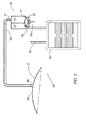
- Fig. 2 shows the disposable portion of the system as an assembly 60, which includes the pump unit 18, the waste bag 31, the connecting tube 16 and the wound enclosure 12, all separated from the drive unit and from the wound area of the body 34.
- the assembly 60 may be disposed of in its totality after use, and replaced by a new assembly, thus keeping the costly drive unit 40 free from any contamination. It would be obvious to those skilled in the art, that the present invention alleviates the need for cleaning or disinfecting any portion of drive unit 40 after use, or providing protective means, such as filters, to keep contaminants from reaching the costly drive 40.
Abstract
Description
- This invention relates generally to wound healing, and more specifically to healing of wounds by negative pressure drainage.
- Negative pressure applied to a wound enhances drainage of fluids or exudate from the wound and promotes tissue growth and wound healing. This method of healing (known as "cupping") was exercised since the times of ancient Greek physicians until the 19th century.
-
WO 96/05873 -
WO 97/18007 -
US 6,648,862 describes a portable vacuum desiccator using a similar arrangement as above, the canister being formed as a cartridge containing a trapping agent (desiccator). The vacuum pump and the canister may be integrated and detachable from the pump motor and circuitry. - Current negative pressure wound drainage systems such as the ones described above suffer from the following deficiencies:
- Since the negative pressure applied to the wound area is created by pump suction, the flow into the pump is likely to contaminate the pump, or conversely, to require costly and complex methods of isolating the pump from the wound exudate such as antibacterial filters.
- The wound exudate is collected in a rigid canister, which must be large enough to prevent it from over-flowing, and thus it is bulky and an inconvenient burden for ambulatory patients, who carry a portable system with them.
- Conventional wound drainage systems utilize an air tight seal of the wound, which is helpful in obtaining and maintaining negative pressure, but requires a pressure relief or bleed valve to produce the pressure cycling desirable to obtain accelerated wound closure, as described in
WO 96/05873 - A sealed wound dressing or enclosure, when under negative pressure, will promote migration of the exudate toward the negative pressure source, through the connecting tube, which may occlude, should the exudate coagulate.
- The need to monitor and control the negative pressure level in conventional systems requires the use of a vacuum transducer, gage or relief valve, which must be connected to the suction tube, which is subject to contamination. Cleaning, disinfecting or isolating the negative pressure monitoring or controlling device are complex, costly and un-reliable.
- It is the purpose of this invention to alleviate all the above listed deficiencies, by providing a wound drainage enclosure and vacuum system, which are impervious to contamination and easy to use.
- In accordance with a first aspect of the present invention, there is provided an enclosure for draining an open wound from liquids exuded therefrom. The enclosure is attachable to the wound circumference so as to define a confined volume, and has an outlet, for example formed as a nipple, connectable by means of a tube to an inlet of a vacuum pump so that negative pressure may be created in said confined volume. One or more bleeding holes are provided in the enclosure or adjacent to its outlet such that ambient air can enter the tube and flow together with the exuded liquids when negative pressure is present. Ambient pressure may be restored in the confined volume when the vacuum pump is not operating.
- The bleeding hole in the enclosure may be a calibrated orifice or other flow restrictors providing for controlled flow of ambient air into the enclosure or into its outlet. For instance, a hole plugged with open cell foam or an open pore sintered metal plug, which restrict the flow, but are not susceptible to plugging as is a small orifice.
- The bleeding hole renders the wound closure vented or non-airtight, as distinguishable from conventional wound closures. The flow of air from the bleeding hole in the wound closure, in response to the negative pressure created by the vacuum pump, facilitates the removal of exudate, which might otherwise coagulate, dry-up and occlude the tubing.
- According to another aspect of the present invention, there is provided a method for draining an open wound from liquids exuded therefrom. The method includes:
- providing an enclosure and sealing it to the wound circumference so as to define a confined volume,
- connecting the confined volume to a vacuum pump,
- connecting a waste container for collection of drained liquids to the vacuum pump, and
- operating said vacuum pump to draw the exuded liquids from the wound.
- The method is characterized in that the confined volume is connected to an inlet of the vacuum pump and the waste container is connected to an outlet of the vacuum pump such that the drained liquids flow through said vacuum pump.
- The method may include employment of an enclosure with bleeding orifices so that ambient air is allowed to enter the tube and flow together with the drained exuded liquids.
- Preferably, gases are separated and released from the drained exuded liquids.
- According to a further aspect of the present invention, there is provided a vacuum system for practicing the above method. The vacuum system may use a totally disposable vacuum pump, together with a waste collection bag, as disclosed in
WO03016719 - The vacuum system may be adapted to be carried by an ambulatory patient.
- According with a next aspect of the present invention, there is provided a disposable assembly for draining an open wound from liquids exuded therefrom. The assembly comprises an enclosure attachable to the wound circumference so as to define a confined volume, a vacuum pump unit connected to the enclosure so that negative pressure may be created in the confined volume, and a waste container connected to the vacuum pump unit. The vacuum pump unit has means for detachably attaching to a drive unit for operating the pump unit. The enclosure is connected to an inlet of the vacuum pump unit and the waste container is connected to an outlet of the vacuum pump unit, such that when the vacuum pump unit is operated the drained liquids flow therethrough.
- Preferably, the pump unit and the drive unit are adapted for attaching and detaching by simple hand manipulations.
- The enclosure may have bleeding holes as described above.
- The vacuum pump unit is preferably a two-chambered diaphragm pump adapted for pumping gases and liquids and/or any combination thereof.
- The waste container may contain a porous media adapted to soak up the drained liquids and may be in the form of a collapsible or foldable bag.
- The drained liquids and air contact only the parts of the disposable assembly. The drained exuded liquids may then be disposed of together with the disposable assembly. More specifically, the pump unit is disposed of after use, together with the tubing connected to it, as well as the waste bag connected, with its content, and with the wound closure which may be connected to the pump unit via the tube.
- In accordance with yet another aspect of the present invention, there is provided a vacuum system as described above where the vacuum pump has a drive unit and a control block adapted to power the drive unit so that a predetermined level of negative pressure is maintained in the confined volume. The control block has a sensor for sensing working parameters of the drive unit and means for deriving the level of negative pressure in the confined volume from these working parameters, in order to maintain said predetermined level. The sensor has no fluid connection with the confined volume.
- For example, the drive unit may comprise a direct current electric motor and the sensor may sense the electric current driving the motor. The same function of negative pressure control may be accomplished by an adjustable torque limiting clutch, placed between the motor output shaft and the pump.
- The control block may be provided with alarm means to warn the user if the predetermined level of negative pressure is not maintained.
- If the vacuum pump comprises a disposable pump unit and the drive unit is detachably attachable to the pump unit, the control block with monitoring means is preferably associated with the drive unit which is non-disposable.
- Thus, indirect means are provided for controlling or monitoring the level of negative pressure applied to the wound, without making any direct connection to a vacuum sensor, transducer or gage to any portion of the system, which has the negative pressure applied to it. The indirect negative pressure monitoring and control result from the need to dispose of any portion of the system, which may come in contact with the pumped media, which is likely to be contaminated or infectious. Accordingly, all the disposable components in the system may be relatively low in cost, to promote discarding them after use. Pressure transducers, vacuum gages or sensors, are relatively costly, and thus not considered disposable.
- In order to understand the invention and to see how it may be applied, a preferred embodiment will now be described, by way of non-limiting example only, with reference to the accompanying drawings, in which:
-
Fig. 1 is a schematic sectional view of the vacuum system of the present invention applied on a wound. -
Fig. 2 shows the disposable portion of the system ofFig. 1 . - The present invention provides a system and a method of treating and healing of a body wound, by applying a negative pressure to the wound, over an area sufficient to promote migration of epithelial and subcutaneous tissue toward the wound.
- It is appreciated that the detailed description that follows is intended only to illustrate certain preferred embodiments of the present invention. It is in no way intended to limit the scope of the invention, as set out in the claims.
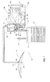
- With reference to
Fig. 1 , in accordance with the present invention, avacuum system 10 for draining an open wound from liquids exuded therefrom comprises awound enclosure 12, avacuum pump 14, andwaste collection bag 31. Thewound enclosure 12 is connected by asuction tube 16 to aninlet 11 of the vacuum pump. Thewaste collection bag 31 is connected to anoutlet 22 of the vacuum pump. Thereby, when thevacuum pump 14 is operated, the drained liquids flow through the pump into thewaste bag 31. -
Suction tube 16 is connected to nipple 38 of theenclosure 12 which covers wound area of thebody 34 such that suction of air throughtube 16 creates negative pressure in the volume above the wound area of thebody 34. A bleedingorifice 35 is provided within theenclosure 12, or adjacent to it as atube orifice 37, allowing ambient air to flow into and throughsuction tube 16,rendering enclosure 12 non-air tight, or vented. This feature, unlike conventional sealed closures, provides for quick movement of exudate enteringsuction tube 16, toward thevacuum pump 14, and into thewaste bag 31, before it dries up or coagulates and occludes the tube. This feature also provides for introduction of ambient pressure to the wound area of thebody 34 whenever the vacuum pump stops pumping, allowing cyclic negative pressure application to the wound, by cycling the vacuum pump on and off alternately. - Instead of the bleeding
orifice 35 in the enclosure, other flow restrictors may be used to provide for controlled flow of ambient air into the enclosure or into the outlet. For instance, a hole plugged with open cell foam or an open pore sintered metal plug, which restrict the flow, but are not susceptible to plugging as is a small orifice. - The
vacuum pump 14 comprises apump unit 18 and adrive unit 40 which are detachably attachable to each other, as explained below. Thepump unit 18 includes a two-chamberedhousing 17 and adiaphragm 24 secured to the underside of the two-chamberedhousing 17 so as to form a workingchamber 29. - The two-chambered
housing 17 has afirst chamber 13 with theinlet 11 and asecond chamber 21 with anoutlet 22. Thesuction tube 16 is connected to theinlet 11. Two one-way valves first chamber 13 and thesecond chamber 21, respectively. To the bottom of the two-chamberedhousing 17 there is attached a mountingbase 23, used to mount thehousing 17 to thedrive unit 40 by means of a bayonet lock. - The
diaphragm 24 has an integral rod-shapeddrive member 25, which is used for engagement with thedrive unit 40. - The
drive unit 40 includes anelectric motor 39, batteries 41 and acontrol block 50 described below. The shaft of themotor 39 has acrank 27 coupled to areciprocating rod 26. Therod 26 has a receptacle with a cavity adapted to receive and lock therein thedrive member 25. - When the
pump unit 18 is attached to thedrive unit 40 by means of the bayonet lock in thebase 23, thedrive member 25 is received in the receptacle cavity of the reciprocatingrod 26 and then locked therein. - Upon activation of the
motor 39, thecrank 27 is rotated and reciprocates thereceptacle rod 26, causing thediaphragm 24 to expand and contract the workingchamber 29. Thus thepump unit 18 pumps air or liquid that passes through the one-way valves - Air and liquids enter the two-chambered
housing 17 through theinlet 11 andsuction tube 16 which is connected to the patient'swound enclosure 12, for the removal of exudate. Liquids and air enter thefirst chamber 13, which is under negative pressure when diaphragm 24 reciprocates, driving them past one-way valve 20, into thesecond chamber 21. The air and liquid which are pumped throughoutlet 22, enterwaste bag 31. - The pump's ability to pump air and liquid, unlike conventional pumps, which are efficient in pumping only one type of matter, is enhanced by the flexibility of the
diaphragm 24 which allows the diaphragm to yield when encountering heavy loads, such as those present when pumping liquid. This diaphragm flexibility also provides an additional substantial advantage: when the negative pressure in workingchamber 29 is high, thediaphragm 24 stretches to allow the reciprocation of thereceptacle rod 26 to occur, at minimal burden to theelectric motor 39. - The
waste bag 31 has avent 15, through which air and gas are discharged to the atmosphere. Accordingly,waste bag 31 will retain only the waste fluids which are pumped into it. The waste bag may contain aporous media 47 adapted to soak up the drained liquids. - It is important to note that
waste bag 31 is made of thin plastic sheet, which allow it to be folded or collapsed when not full, providing the convenience of having minimal bulk and minimal inconvenience to the patient using or carrying it. - The
drive unit 40 also includes acontrol block 50 with control circuits such ascycle control 42, which turns the motor pump on and off alternately, motor voltage and current monitoring andcontrol 43, which controls the negative pressure level produced by thepump unit 18, by controlling the voltage and current which drivemotor 39. At any given voltage which drivesmotor 39, the current draw of the motor is directly related to the negative pressure generated by thepump 18. Accordingly, monitoring of the current which themotor 39 draws allows for indirect monitoring of the negative pressure attained bypump 18. The ability to monitor the negative pressure developed bypump 18, indirectly, precludes the need of making an infectious negative pressure line connection to a pressure transducer or vacuum gage. - For example, if the
motor 39 is a direct current electric motor, a sensor may sense the electric current driving the motor. Since the direct current motor output torque is directly related to the current driving the motor, and since the motor output torque is directly related to the negative pressure thepump 18 produces, monitoring the motor current or controlling it, provide for monitoring and controlling the negative pressure produced by the vacuum pump. Motor current monitoring is only one of the available methods of indirect negative pressure monitoring and controlling. The same function of negative pressure control may be accomplished by an adjustable torque limiting clutch placed between the motor output shaft and thecrank 27. - The
control block 50 also has anegative pressure comparator 44, which compares the desired set negative pressure level obtained bypump 18, and the actual monitored negative pressure level as obtained indirectly from motor voltage and current monitoring andcontrol 43.Comparator 44 will activateaudible alarm 45, wheneverpump 18 fails to reach the desired pre-set negative pressure level. -
Fig. 2 shows the disposable portion of the system as anassembly 60, which includes thepump unit 18, thewaste bag 31, the connectingtube 16 and thewound enclosure 12, all separated from the drive unit and from the wound area of thebody 34. Theassembly 60 may be disposed of in its totality after use, and replaced by a new assembly, thus keeping thecostly drive unit 40 free from any contamination. It would be obvious to those skilled in the art, that the present invention alleviates the need for cleaning or disinfecting any portion ofdrive unit 40 after use, or providing protective means, such as filters, to keep contaminants from reaching thecostly drive 40.
Claims (15)
- A vacuum system for draining an open wound from liquids exuded therefrom, comprising an enclosure sealable to the wound circumference so as to define a confined volume, a vacuum pump in fluid communication with said confined volume, and a waste container for collection of drained liquids in fluid communication with said vacuum pump,
wherein said confined volume is connected to an inlet of said vacuum pump and said waste container is connected to an outlet of said vacuum pump, such that when said vacuum pump is operated the drained liquids flow through said vacuum pump; and
wherein said enclosure has an enclosure outlet connected by means of a tube to said inlet of the vacuum pump, and one or more bleeding holes are provided through said enclosure or adjacent to said enclosure outlet so that ambient air may enter said tube and flow together with the drained liquids. - The vacuum system of Claim 1, wherein said vacuum pump includes a disposable pump unit detachably attachable to a non-disposable drive unit, said enclosure and said waste container being disposable so that the drained liquids, as well as air coming in contact with them, contact only the disposable elements and said drained liquids may be disposed of together with said disposable elements.
- The vacuum system of Claim 2, wherein said pump unit and said drive unit are adapted for attaching and detaching by simple hand manipulations
- The vacuum system of Claim 1, wherein said vacuum pump is a two-chambered diaphragm pump adapted for pumping gases and liquids and/or any combination thereof.
- The vacuum system of Claim 1, wherein a said bleeding hole comprises a tube orifice comprised in said tube.
- An enclosure for draining an open wound from liquids exuded therefrom, the enclosure being attachable to the wound circumference so as to define a confined volume, and having an enclosure outlet connectable by means of a tube to an inlet of a vacuum pump so that negative pressure may be created in said volume,
wherein one or more bleeding holes are provided in the enclosure or adjacent to said enclosure outlet such that ambient air can enter said tube and flow together with the exuded liquids under the action of the negative pressure, and the ambient pressure may be restored in said confined volume when said vacuum pump is not operating. - The enclosure of Claim 6, having a nipple for connecting to said tube.
- The enclosure of Claim 6, wherein a plurality of bleeding holes is provided in the form of a porous body mounted in said enclosure.
- The enclosure of Claim 6, comprising a tube connected to said outlet, for connection to the vacuum pump inlet.
- The enclosure of Claim 6, wherein said one or more bleeding holes are provided in the tube, adjacent to said outlet.
- The enclosure of Claim 6, wherein said outlet of said enclosure is connectable to the inlet of a vacuum pump via a chamber.
- A disposable assembly for draining an open wound from liquids exuded therefrom, the assembly comprising an enclosure attachable to the wound circumference so as to define a confined volume, a vacuum pump unit connected to said enclosure so that negative pressure may be created in said volume, said vacuum pump unit having means for detachably attaching to a drive unit for operating the pump unit, and a waste container connected to said vacuum pump unit;
wherein said enclosure is connected to an inlet of said vacuum pump unit and said waste container is connected to an outlet of said vacuum pump unit, such that when said vacuum pump unit is operated the drained liquids flow therethrough; and
wherein said enclosure has an enclosure outlet connected by means of a tube to said inlet of the vacuum pump unit, and one or more bleeding holes are provided through said enclosure or adjacent to said enclosure outlet so that ambient air may flow through said tube together with the drained exuded liquids. - The assembly of Claim 12, wherein said one or more bleeding holes are provided in the tube, adjacent to said outlet.
- A vacuum system for draining an open wound from liquids exuded therefrom, comprising an enclosure sealable to the wound circumference so as to define a confined volume, a chamber, and a vacuum pump in fluid communication with said confined volume via said chamber,
wherein said confined volume is connected to an inlet of said chamber and said vacuum pump is connected to an outlet of said chamber; and
wherein said enclosure has an outlet connected by means of a tube to said inlet of the chamber, and one or more bleeding holes are provided through said enclosure or adjacent to its outlet so that ambient air may enter said tube and flow together with the drained liquids. - The vacuum system of Claim 14, wherein a said bleeding hole comprises a tube orifice comprised in said tube.
Priority Applications (2)
| Application Number | Priority Date | Filing Date | Title |
|---|---|---|---|
| ES09165687.6T ES2391527T5 (en) | 2005-07-24 | 2005-07-24 | Drainage and wound closure system |
| EP09165687.6A EP2127690B2 (en) | 2005-07-24 | 2005-07-24 | Wound closure and drainage system |
Applications Claiming Priority (3)
| Application Number | Priority Date | Filing Date | Title |
|---|---|---|---|
| EP05762092A EP1909863A1 (en) | 2005-07-24 | 2005-07-24 | Wound closure and drainage system |
| EP09165687.6A EP2127690B2 (en) | 2005-07-24 | 2005-07-24 | Wound closure and drainage system |
| PCT/IL2005/000784 WO2007013049A1 (en) | 2005-07-24 | 2005-07-24 | Wound closure and drainage system |
Related Parent Applications (2)
| Application Number | Title | Priority Date | Filing Date |
|---|---|---|---|
| EP05762092A Division EP1909863A1 (en) | 2005-07-24 | 2005-07-24 | Wound closure and drainage system |
| EP05762092.4 Division | 2005-07-24 |
Publications (4)
| Publication Number | Publication Date |
|---|---|
| EP2127690A2 true EP2127690A2 (en) | 2009-12-02 |
| EP2127690A3 EP2127690A3 (en) | 2010-03-10 |
| EP2127690B1 EP2127690B1 (en) | 2012-06-20 |
| EP2127690B2 EP2127690B2 (en) | 2017-06-14 |
Family
ID=35929816
Family Applications (2)
| Application Number | Title | Priority Date | Filing Date |
|---|---|---|---|
| EP05762092A Withdrawn EP1909863A1 (en) | 2005-07-24 | 2005-07-24 | Wound closure and drainage system |
| EP09165687.6A Active EP2127690B2 (en) | 2005-07-24 | 2005-07-24 | Wound closure and drainage system |
Family Applications Before (1)
| Application Number | Title | Priority Date | Filing Date |
|---|---|---|---|
| EP05762092A Withdrawn EP1909863A1 (en) | 2005-07-24 | 2005-07-24 | Wound closure and drainage system |
Country Status (7)
| Country | Link |
|---|---|
| US (5) | US8506554B2 (en) |
| EP (2) | EP1909863A1 (en) |
| JP (1) | JP4970445B2 (en) |
| CN (1) | CN101227937A (en) |
| CA (1) | CA2614794C (en) |
| ES (1) | ES2391527T5 (en) |
| WO (1) | WO2007013049A1 (en) |
Cited By (18)
| Publication number | Priority date | Publication date | Assignee | Title |
|---|---|---|---|---|
| WO2011094410A3 (en) * | 2010-01-29 | 2011-12-08 | Kci Licensing, Inc | Wound treatment apparatuses and methods for controlled delivery of fluids to a wound |
| EP2480264A1 (en) * | 2009-09-22 | 2012-08-01 | Medela Holding AG | Device and method for expressing human breast milk |
| CN103028189A (en) * | 2011-10-10 | 2013-04-10 | 美昕医疗器械(上海)有限公司 | Medical waste liquid collection system |
| US8734410B2 (en) | 2007-12-06 | 2014-05-27 | Smith & Nephew Plc | Apparatus for topical negative pressure therapy |
| US8801685B2 (en) | 2009-12-22 | 2014-08-12 | Smith & Nephew, Inc. | Apparatuses and methods for negative pressure wound therapy |
| US9050398B2 (en) | 2010-12-22 | 2015-06-09 | Smith & Nephew, Inc. | Apparatuses and methods for negative pressure wound therapy |
| US9227000B2 (en) | 2006-09-28 | 2016-01-05 | Smith & Nephew, Inc. | Portable wound therapy system |
| US9474654B2 (en) | 2008-08-08 | 2016-10-25 | Smith & Nephew, Inc. | Wound dressing of continuous fibers |
| US9907703B2 (en) | 2012-05-23 | 2018-03-06 | Smith & Nephew Plc | Apparatuses and methods for negative pressure wound therapy |
| US9956329B2 (en) | 2008-03-07 | 2018-05-01 | Smith & Nephew, Inc. | Wound dressing port and associated wound dressing |
| US10010658B2 (en) | 2013-05-10 | 2018-07-03 | Smith & Nephew Plc | Fluidic connector for irrigation and aspiration of wounds |
| US10406036B2 (en) | 2009-06-18 | 2019-09-10 | Smith & Nephew, Inc. | Apparatus for vacuum bridging and/or exudate collection |
| US10537657B2 (en) | 2010-11-25 | 2020-01-21 | Smith & Nephew Plc | Composition I-II and products and uses thereof |
| USRE48117E1 (en) | 2010-05-07 | 2020-07-28 | Smith & Nephew, Inc. | Apparatuses and methods for negative pressure wound therapy |
| US11154649B2 (en) | 2015-05-18 | 2021-10-26 | Smith & Nephew Plc | Fluidic connector for negative pressure wound therapy |
| US11638666B2 (en) | 2011-11-25 | 2023-05-02 | Smith & Nephew Plc | Composition, apparatus, kit and method and uses thereof |
| US11931226B2 (en) | 2013-03-15 | 2024-03-19 | Smith & Nephew Plc | Wound dressing sealant and use thereof |
| US11938231B2 (en) | 2010-11-25 | 2024-03-26 | Smith & Nephew Plc | Compositions I-I and products and uses thereof |
Families Citing this family (77)
| Publication number | Priority date | Publication date | Assignee | Title |
|---|---|---|---|---|
| US7625362B2 (en) * | 2003-09-16 | 2009-12-01 | Boehringer Technologies, L.P. | Apparatus and method for suction-assisted wound healing |
| GB0224986D0 (en) | 2002-10-28 | 2002-12-04 | Smith & Nephew | Apparatus |
| US11298453B2 (en) | 2003-10-28 | 2022-04-12 | Smith & Nephew Plc | Apparatus and method for wound cleansing with actives |
| GB0325129D0 (en) | 2003-10-28 | 2003-12-03 | Smith & Nephew | Apparatus in situ |
| US10058642B2 (en) | 2004-04-05 | 2018-08-28 | Bluesky Medical Group Incorporated | Reduced pressure treatment system |
| GB0508531D0 (en) | 2005-04-27 | 2005-06-01 | Smith & Nephew | Sai with ultrasound |
| US8197231B2 (en) | 2005-07-13 | 2012-06-12 | Purity Solutions Llc | Diaphragm pump and related methods |
| US7438705B2 (en) | 2005-07-14 | 2008-10-21 | Boehringer Technologies, L.P. | System for treating a wound with suction and method detecting loss of suction |
| US7857806B2 (en) | 2005-07-14 | 2010-12-28 | Boehringer Technologies, L.P. | Pump system for negative pressure wound therapy |
| WO2007013049A1 (en) | 2005-07-24 | 2007-02-01 | Carmeli Adahan | Wound closure and drainage system |
| US7569742B2 (en) | 2005-09-07 | 2009-08-04 | Tyco Healthcare Group Lp | Self contained wound dressing with micropump |
| US7779625B2 (en) | 2006-05-11 | 2010-08-24 | Kalypto Medical, Inc. | Device and method for wound therapy |
| US9820888B2 (en) | 2006-09-26 | 2017-11-21 | Smith & Nephew, Inc. | Wound dressing |
| EP2081618B1 (en) | 2006-10-13 | 2016-01-06 | Bluesky Medical Group Inc. | Improved control circuit and apparatus for negative pressure wound treatment |
| CA2673842C (en) * | 2007-02-09 | 2012-12-04 | Kci Licensing, Inc. | System and method for managing reduced pressure at a tissue site |
| CN101678155A (en) | 2007-05-07 | 2010-03-24 | 卡尔梅利·阿达汗 | Suction system |
| WO2009016603A2 (en) * | 2007-08-01 | 2009-02-05 | Blackbeard, Graham Alan | Reduced pressure wound treatment apparatus |
| DE102007045265B4 (en) | 2007-09-21 | 2018-06-28 | Continental Automotive Gmbh | Method and device for operating a diaphragm pump |
| HUE041864T2 (en) | 2007-11-21 | 2019-06-28 | Smith & Nephew | Wound dressing |
| GB0722820D0 (en) | 2007-11-21 | 2008-01-02 | Smith & Nephew | Vacuum assisted wound dressing |
| AU2008327660B2 (en) | 2007-11-21 | 2014-02-13 | Smith & Nephew Plc | Wound dressing |
| GB0724564D0 (en) * | 2007-12-18 | 2008-01-30 | Smith & Nephew | Portable wound therapy apparatus and method |
| US8021347B2 (en) | 2008-07-21 | 2011-09-20 | Tyco Healthcare Group Lp | Thin film wound dressing |
| US8298200B2 (en) | 2009-06-01 | 2012-10-30 | Tyco Healthcare Group Lp | System for providing continual drainage in negative pressure wound therapy |
| KR20110042214A (en) | 2008-08-08 | 2011-04-25 | 케이씨아이 라이센싱 인코포레이티드 | Reduced-pressure treatment systems with reservoir control |
| US8162907B2 (en) | 2009-01-20 | 2012-04-24 | Tyco Healthcare Group Lp | Method and apparatus for bridging from a dressing in negative pressure wound therapy |
| US8882678B2 (en) | 2009-03-13 | 2014-11-11 | Atrium Medical Corporation | Pleural drainage system and method of use |
| EP2419157A4 (en) | 2009-04-17 | 2018-01-03 | Kalypto Medical, Inc. | Negative pressure wound therapy device |
| KR101063342B1 (en) * | 2009-12-04 | 2011-09-07 | 주식회사 바이오알파 | Portable vacuum generator and medical suction device using same |
| US8791315B2 (en) | 2010-02-26 | 2014-07-29 | Smith & Nephew, Inc. | Systems and methods for using negative pressure wound therapy to manage open abdominal wounds |
| US8821458B2 (en) | 2010-04-16 | 2014-09-02 | Kci Licensing, Inc. | Evaporative body-fluid containers and methods |
| US9061095B2 (en) | 2010-04-27 | 2015-06-23 | Smith & Nephew Plc | Wound dressing and method of use |
| TW201200109A (en) * | 2010-06-22 | 2012-01-01 | Apex Medical Corp | Feedback control method of negative pressure wound care system and negative pressure wound care system |
| TW201200185A (en) * | 2010-06-22 | 2012-01-01 | Apex Medical Corp | Liquid-collecting device for negative pressure wound care system and its assembly |
| GB201011173D0 (en) | 2010-07-02 | 2010-08-18 | Smith & Nephew | Provision of wound filler |
| US20120053542A1 (en) * | 2010-08-31 | 2012-03-01 | Apex Medical Corp. | Actuator for a negative pressure wound therapy system |
| FR2965182B1 (en) * | 2010-09-27 | 2013-05-31 | Apex Medical Corp | COLLECTOR FOR NEGATIVE PRESSURE WOUND TREATMENT SYSTEM AND COMBINATION OF SUCH COLLECTORS |
| USD714433S1 (en) | 2010-12-22 | 2014-09-30 | Smith & Nephew, Inc. | Suction adapter |
| CN102068750B (en) * | 2011-01-26 | 2013-05-15 | 惠州市华阳医疗电子有限公司 | System equipment management-based negative pressure wound therapy system |
| US8979823B2 (en) * | 2011-02-09 | 2015-03-17 | Apnicure, Inc. | Saliva management system with continuous flow through oral device |
| CN103517665B (en) * | 2011-03-11 | 2016-06-29 | L&R国际有限责任及两合公司 | Vacuum system and endoscope apparatus for endoscope's vacuum-therapy |
| US9058634B2 (en) | 2011-05-24 | 2015-06-16 | Kalypto Medical, Inc. | Method for providing a negative pressure wound therapy pump device |
| CA2837181A1 (en) | 2011-05-24 | 2012-11-29 | Kalypto Medical, Inc. | Device with controller and pump modules for providing negative pressure for wound therapy |
| US9067003B2 (en) | 2011-05-26 | 2015-06-30 | Kalypto Medical, Inc. | Method for providing negative pressure to a negative pressure wound therapy bandage |
| TW201249489A (en) | 2011-06-01 | 2012-12-16 | Suzric Entpr Co Ltd | Wound drainage equipment, conduit, connector and wound cover |
| CN102805895A (en) * | 2011-06-01 | 2012-12-05 | 暄达实业股份有限公司 | Wound drainage device, connection pipe fitting, connector and wound cover piece |
| WO2012174672A1 (en) * | 2011-06-23 | 2012-12-27 | Medela Holding Ag | System for aspirating fluids from a body by means of a vacuum |
| CN103917257B (en) * | 2011-11-23 | 2019-02-15 | 凯希特许有限公司 | With reduced-pressure dressings and the reduced pressure processing system and method that are associated with valve |
| DE102012101642A1 (en) * | 2012-02-29 | 2013-08-29 | DüRR DENTAL AG | Suction machine with housing made of expanded plastic |
| US9610392B2 (en) | 2012-06-08 | 2017-04-04 | Fresenius Medical Care Holdings, Inc. | Medical fluid cassettes and related systems and methods |
| AU2013298195B2 (en) | 2012-08-01 | 2017-07-13 | Smith & Nephew Plc | Wound dressing |
| AU2013298198B2 (en) | 2012-08-01 | 2017-05-11 | Smith & Nephew Plc | Wound dressing |
| GB201216928D0 (en) | 2012-09-21 | 2012-11-07 | I2R Medical Ltd | Portable medical device system |
| JP2016508056A (en) * | 2013-01-03 | 2016-03-17 | ケーシーアイ ライセンシング インコーポレイテッド | Rechargeable negative pressure closure therapy |
| BR112015020855A2 (en) | 2013-03-15 | 2017-07-18 | Smith & Nephew | wound dressing and treatment method |
| DE102013208107A1 (en) * | 2013-05-03 | 2014-11-06 | Paul Hartmann Ag | Fluid receptacle for a device for providing negative pressure for medical applications, and device |
| CN105744918B (en) * | 2013-10-02 | 2020-11-20 | 凯希特许有限公司 | Disposable reduced pressure treatment system with electronic feedback |
| DE102014002204B3 (en) * | 2014-02-21 | 2015-01-08 | Alexander May | Device for negative pressure wound treatment |
| WO2016024169A2 (en) * | 2014-08-14 | 2016-02-18 | Coeo Labs Private Limited | Systems and methods for automatically removing fluid from multiple regions of a respiratory tract |
| EP3590555B1 (en) | 2014-09-10 | 2023-08-30 | 3M Innovative Properties Company | Therapy apparatus with integrated fluid conductors and noise attenuation |
| US10821199B2 (en) * | 2014-12-22 | 2020-11-03 | Bluewave Technologies, Inc. | Plasma treatment device and method of treating items |
| US10088398B2 (en) | 2015-02-11 | 2018-10-02 | Emd Millipore Corporation | Stirred cell and method of using same |
| USD804653S1 (en) | 2015-06-12 | 2017-12-05 | Emd Millipore Corporation | Pressure vessel |
| CH711436A1 (en) * | 2015-08-20 | 2017-02-28 | Medmix Systems Ag | Diaphragm pump with medium separation. |
| AU2017227923B2 (en) | 2016-03-04 | 2022-01-27 | Smith & Nephew Plc | Negative pressure wound therapy apparatus for post breast surgery wounds |
| ES2707798T3 (en) * | 2016-09-06 | 2019-04-05 | FRITZ RUCK Ophthalmologische Systeme GmbH | Pressure regulation system |
| CN107865701B (en) * | 2016-09-27 | 2023-10-13 | 惠州科赛医疗有限公司 | Medical pump fixing device |
| CA3038282A1 (en) | 2016-09-29 | 2018-04-05 | Smith & Nephew Plc | Protection of electronics in negative pressure wound therapy systems |
| CN107126235B (en) * | 2017-06-23 | 2019-11-19 | 吉林大学 | A kind of bronchoscope lower respiratory tract secretion receiving flask |
| GB201804971D0 (en) | 2018-03-28 | 2018-05-09 | Smith & Nephew | Electrostatic discharge protection for sensors in wound therapy |
| GB201718014D0 (en) | 2017-11-01 | 2017-12-13 | Smith & Nephew | Dressing for negative pressure wound therapy with filter |
| CN108030967B (en) * | 2017-12-15 | 2020-06-09 | 惠州市爱尼宝母婴用品有限公司 | Method for the suction stabilization of a breast pump |
| CN108310480A (en) * | 2018-02-07 | 2018-07-24 | 苏州元禾医疗器械有限公司 | A kind of Wound treating equipment liquid level controlling method |
| GB201811449D0 (en) | 2018-07-12 | 2018-08-29 | Smith & Nephew | Apparatuses and methods for negative pressure wound therapy |
| US10531883B1 (en) * | 2018-07-20 | 2020-01-14 | Syntheon 2.0, LLC | Aspiration thrombectomy system and methods for thrombus removal with aspiration catheter |
| CN110251741A (en) * | 2019-05-30 | 2019-09-20 | 天津市同业科技发展有限公司 | It is a kind of to can be realized the Multifunctional central attraction system remotely monitored |
| CN112316224A (en) * | 2020-11-23 | 2021-02-05 | 南京宁星医疗科技有限公司 | Negative pressure wound drainage device for big fish |
Citations (7)
| Publication number | Priority date | Publication date | Assignee | Title |
|---|---|---|---|---|
| FR1163907A (en) | 1956-10-25 | 1958-10-02 | Skin care devices | |
| US3730209A (en) | 1971-06-02 | 1973-05-01 | Kendall & Co | Vent for liquid drainage system |
| WO1996005873A1 (en) | 1994-08-22 | 1996-02-29 | Kinetic Concepts Inc. | Wound drainage equipment |
| WO1997018007A1 (en) | 1995-11-14 | 1997-05-22 | Kci Medical Limited | Portable wound treatment apparatus |
| WO2001078827A1 (en) | 2000-04-18 | 2001-10-25 | Thomas Hausmann | Drainage device for dressing wounds |
| WO2003016719A1 (en) | 2001-08-14 | 2003-02-27 | Carmeli Adahan | A compact vacuum pump |
| US6648862B2 (en) | 2001-11-20 | 2003-11-18 | Spheric Products, Ltd. | Personally portable vacuum desiccator |
Family Cites Families (67)
| Publication number | Priority date | Publication date | Assignee | Title |
|---|---|---|---|---|
| US599333A (en) * | 1898-02-22 | George w | ||
| US1599899A (en) * | 1923-09-26 | 1926-09-14 | Delco Light Co | Diaphragm pump |
| US3026874A (en) * | 1959-11-06 | 1962-03-27 | Robert C Stevens | Wound shield |
| US3416461A (en) * | 1966-09-01 | 1968-12-17 | Hills Mccanna Co | Diaphragm pump |
| US3516160A (en) * | 1968-03-18 | 1970-06-23 | Pelton & Crane Co | Dental aspirating cuspidor |
| US3864979A (en) | 1973-03-30 | 1975-02-11 | Becton Dickinson Co | Blood sedimentation tube barrier |
| DE2401643C2 (en) | 1974-01-15 | 1982-04-01 | Tuchenhagen, Otto, 2059 Büchen | Process for proportional metering in sludge pumps that work on filter presses |
| US3918453A (en) * | 1974-07-01 | 1975-11-11 | Baxter Laboratories Inc | Surgical suction device |
| NL7703439A (en) * | 1976-04-09 | 1977-10-11 | Pumpex Production Ab | PROCEDURE FOR CONTROLLING A HYDRODYNAMIC PUMP UNIT AND REGULATOR FOR APPLYING THE PROCEDURE. |
| US4108574A (en) * | 1977-01-21 | 1978-08-22 | International Paper Company | Apparatus and method for the indirect measurement and control of the flow rate of a liquid in a piping system |
| MX154678A (en) * | 1981-10-28 | 1987-09-23 | Armando Gamboa Mayoral | AUTOMATION TO DESTROY THE SUCTION CANNULA OF SURGICAL VACUUM CLEANERS DURING USE |
| DE3205445A1 (en) | 1982-02-16 | 1983-08-25 | Fa. Wilhelm Schade, 5970 Plettenberg | Vehicle roof with a tilt and slide cover arranged in the area of a roof opening |
| DE3205449C2 (en) | 1982-02-16 | 1985-10-17 | Fresenius AG, 6380 Bad Homburg | Device for purifying metabolic products from the blood |
| SE445298B (en) | 1982-11-17 | 1986-06-16 | Gunnar Pontus Em Swanbeck | DEVICE FOR CLEANING AND TREATMENT OF SARS AND INFECTED SKIN PARTIES |
| DE3321151C2 (en) * | 1983-06-11 | 1986-09-18 | Walter Küsnacht Beck | Device for aspirating secretions |
| DE3408331C2 (en) | 1984-03-07 | 1986-06-12 | Fresenius AG, 6380 Bad Homburg | Pumping arrangement for medical purposes |
| DE3419613A1 (en) * | 1984-05-25 | 1985-11-28 | Kirchner & Wilhelm, 7000 Stuttgart | MOTHER MILK SUCTION DEVICE |
| US4740202A (en) * | 1984-10-12 | 1988-04-26 | Haemonetics Corporation | Suction collection device |
| US4611627A (en) * | 1985-02-07 | 1986-09-16 | Donaldson Company, Inc. | Self-venting drain valve |
| US4739791A (en) * | 1987-03-26 | 1988-04-26 | Carmeli Adahan | Fluid collection container particularly useful in suction pumps |
| US4930997A (en) * | 1987-08-19 | 1990-06-05 | Bennett Alan N | Portable medical suction device |
| US5116206A (en) * | 1990-12-11 | 1992-05-26 | Carmeli Adahan | Portable fluid pumping device |
| US5636643A (en) * | 1991-11-14 | 1997-06-10 | Wake Forest University | Wound treatment employing reduced pressure |
| US5645081A (en) * | 1991-11-14 | 1997-07-08 | Wake Forest University | Method of treating tissue damage and apparatus for same |
| US7198046B1 (en) * | 1991-11-14 | 2007-04-03 | Wake Forest University Health Sciences | Wound treatment employing reduced pressure |
| DE4208912C1 (en) * | 1992-03-20 | 1993-05-19 | Rudolf 5300 Bonn De Schoen | |
| US5370610A (en) * | 1993-02-09 | 1994-12-06 | Reynolds; James R. | Surgical drainage tube system |
| GB9400994D0 (en) * | 1994-01-20 | 1994-03-16 | Bristol Myers Squibb Co | Wound dressing |
| US5419687A (en) * | 1994-02-28 | 1995-05-30 | Adahan; Carmeli | Fluid pump and suction pump assembly including same |
| JP3744570B2 (en) * | 1995-07-31 | 2006-02-15 | ピジョン株式会社 | Milking machine |
| US6257847B1 (en) * | 1995-08-03 | 2001-07-10 | Medela, Inc. | Diaphragm pump and pump for double-breast pumping |
| CH690956A5 (en) * | 1995-10-03 | 2001-03-15 | Trimed Ag | Regeleinrichtung, particularly for a Muttermilchabsaugeinrichtung. |
| US5662599A (en) * | 1996-02-20 | 1997-09-02 | No Mulligans, Llc | Disposable wound dressing and support unit |
| US6200292B1 (en) | 1996-06-18 | 2001-03-13 | C. R. Bard, Inc. | Suction and irrigation handpiece and tip |
| US6562013B1 (en) * | 1996-07-11 | 2003-05-13 | Pulsecare Medical Llc | Kit assembly for complete wound treatment |
| US5776119A (en) * | 1996-09-30 | 1998-07-07 | Bilbo; Sharon C. | Portable suction unit |
| US5941859A (en) * | 1997-03-17 | 1999-08-24 | Lerman; Benjamin S. | Wound irrigation shield with fluid scavenging |
| AU7442298A (en) | 1997-05-19 | 1998-12-11 | Harwill Industries (Pty) Limited | Nozzle for surgical suction apparatus |
| US6071267A (en) * | 1998-02-06 | 2000-06-06 | Kinetic Concepts, Inc. | Medical patient fluid management interface system and method |
| US6041801A (en) | 1998-07-01 | 2000-03-28 | Deka Products Limited Partnership | System and method for measuring when fluid has stopped flowing within a line |
| GB9822341D0 (en) | 1998-10-13 | 1998-12-09 | Kci Medical Ltd | Negative pressure therapy using wall suction |
| GB9909301D0 (en) * | 1999-04-22 | 1999-06-16 | Kci Medical Ltd | Wound treatment apparatus employing reduced pressure |
| US20020151826A1 (en) * | 1999-05-11 | 2002-10-17 | John S. Ramey | Massage apparatus and methods |
| US6179804B1 (en) | 1999-08-18 | 2001-01-30 | Oxypatch, Llc | Treatment apparatus for wounds |
| GB9926538D0 (en) | 1999-11-09 | 2000-01-12 | Kci Medical Ltd | Multi-lumen connector |
| US6824533B2 (en) * | 2000-11-29 | 2004-11-30 | Hill-Rom Services, Inc. | Wound treatment apparatus |
| JP4080150B2 (en) | 2000-07-28 | 2008-04-23 | ピジョン株式会社 | Pulsating breast pump |
| US7108683B2 (en) * | 2001-04-30 | 2006-09-19 | Kci Licensing, Inc | Wound therapy and tissue management system and method with fluid differentiation |
| JP2003014819A (en) * | 2001-07-03 | 2003-01-15 | Matsushita Electric Ind Co Ltd | Semiconductor wiring board, semiconductor device, test method therefor and mounting method therefor |
| JP2004534595A (en) * | 2001-07-12 | 2004-11-18 | ヒル−ロム サービシズ,インコーポレイテッド | Control of vacuum rate of change |
| US7004915B2 (en) * | 2001-08-24 | 2006-02-28 | Kci Licensing, Inc. | Negative pressure assisted tissue treatment system |
| WO2003030966A1 (en) | 2001-10-11 | 2003-04-17 | Hill-Rom Services, Inc. | Waste container for negative pressure therapy |
| US6817996B2 (en) * | 2001-12-06 | 2004-11-16 | Microaire Surgical Instruments, Inc. | Liposuction cannula |
| CA2468912A1 (en) | 2001-12-26 | 2003-07-17 | Hill-Rom Services, Inc. | Vented vacuum bandage and method |
| DE10204078B4 (en) * | 2002-02-01 | 2005-05-19 | Eckart Klobe | Suction cup for non-surgical correction of the shape and / or performance of the chest |
| AU2003215342A1 (en) * | 2002-02-21 | 2003-09-09 | Design Mentor, Inc. | Fluid pump |
| DE10215896A1 (en) | 2002-04-11 | 2003-10-23 | Leybold Vakuum Gmbh | vacuum pump |
| US6949066B2 (en) * | 2002-08-21 | 2005-09-27 | World Heart Corporation | Rotary blood pump diagnostics and cardiac output controller |
| US7815616B2 (en) * | 2002-09-16 | 2010-10-19 | Boehringer Technologies, L.P. | Device for treating a wound |
| US7998107B2 (en) * | 2002-09-24 | 2011-08-16 | Kensey Nash Corporation | Interventional procedure drive and control system |
| US6882960B2 (en) * | 2003-02-21 | 2005-04-19 | J. Davis Miller | System and method for power pump performance monitoring and analysis |
| AU2003286079A1 (en) | 2003-12-22 | 2005-07-14 | Medela Holding Ag | Drainage apparatus and method |
| US7128735B2 (en) * | 2004-01-02 | 2006-10-31 | Richard Scott Weston | Reduced pressure wound treatment appliance |
| US8157792B2 (en) * | 2004-02-26 | 2012-04-17 | Haemonetics Corporation | Wound drainage suction relief |
| US7503910B2 (en) * | 2006-02-01 | 2009-03-17 | Carmeli Adahan | Suctioning system, method and kit |
| WO2007013049A1 (en) | 2005-07-24 | 2007-02-01 | Carmeli Adahan | Wound closure and drainage system |
| AU2007300703A1 (en) * | 2006-09-26 | 2008-04-03 | Boehringer Technologies L.P. | Pump system for negative pressure wound therapy |
-
2005
- 2005-07-24 WO PCT/IL2005/000784 patent/WO2007013049A1/en active Application Filing
- 2005-07-24 ES ES09165687.6T patent/ES2391527T5/en active Active
- 2005-07-24 CA CA2614794A patent/CA2614794C/en active Active
- 2005-07-24 EP EP05762092A patent/EP1909863A1/en not_active Withdrawn
- 2005-07-24 JP JP2008523527A patent/JP4970445B2/en active Active
- 2005-07-24 US US11/989,297 patent/US8506554B2/en active Active
- 2005-07-24 EP EP09165687.6A patent/EP2127690B2/en active Active
-
2006
- 2006-07-24 CN CNA2006800271740A patent/CN101227937A/en active Pending
-
2013
- 2013-06-14 US US13/917,865 patent/US8858534B2/en active Active
-
2014
- 2014-10-01 US US14/503,700 patent/US9248222B2/en active Active
-
2015
- 2015-03-30 US US14/672,805 patent/US20150202355A1/en not_active Abandoned
-
2016
- 2016-11-16 US US15/352,971 patent/US20170056572A1/en not_active Abandoned
Patent Citations (7)
| Publication number | Priority date | Publication date | Assignee | Title |
|---|---|---|---|---|
| FR1163907A (en) | 1956-10-25 | 1958-10-02 | Skin care devices | |
| US3730209A (en) | 1971-06-02 | 1973-05-01 | Kendall & Co | Vent for liquid drainage system |
| WO1996005873A1 (en) | 1994-08-22 | 1996-02-29 | Kinetic Concepts Inc. | Wound drainage equipment |
| WO1997018007A1 (en) | 1995-11-14 | 1997-05-22 | Kci Medical Limited | Portable wound treatment apparatus |
| WO2001078827A1 (en) | 2000-04-18 | 2001-10-25 | Thomas Hausmann | Drainage device for dressing wounds |
| WO2003016719A1 (en) | 2001-08-14 | 2003-02-27 | Carmeli Adahan | A compact vacuum pump |
| US6648862B2 (en) | 2001-11-20 | 2003-11-18 | Spheric Products, Ltd. | Personally portable vacuum desiccator |
Cited By (41)
| Publication number | Priority date | Publication date | Assignee | Title |
|---|---|---|---|---|
| US9642955B2 (en) | 2006-09-28 | 2017-05-09 | Smith & Nephew, Inc. | Portable wound therapy system |
| US11141325B2 (en) | 2006-09-28 | 2021-10-12 | Smith & Nephew, Inc. | Portable wound therapy system |
| US10130526B2 (en) | 2006-09-28 | 2018-11-20 | Smith & Nephew, Inc. | Portable wound therapy system |
| US9227000B2 (en) | 2006-09-28 | 2016-01-05 | Smith & Nephew, Inc. | Portable wound therapy system |
| US10561769B2 (en) | 2007-12-06 | 2020-02-18 | Smith & Nephew Plc | Apparatus for topical negative pressure therapy |
| US8734410B2 (en) | 2007-12-06 | 2014-05-27 | Smith & Nephew Plc | Apparatus for topical negative pressure therapy |
| US9801985B2 (en) | 2007-12-06 | 2017-10-31 | Smith & Nephew Plc | Apparatus for topical negative pressure therapy |
| US9956329B2 (en) | 2008-03-07 | 2018-05-01 | Smith & Nephew, Inc. | Wound dressing port and associated wound dressing |
| US9474654B2 (en) | 2008-08-08 | 2016-10-25 | Smith & Nephew, Inc. | Wound dressing of continuous fibers |
| US10406036B2 (en) | 2009-06-18 | 2019-09-10 | Smith & Nephew, Inc. | Apparatus for vacuum bridging and/or exudate collection |
| US10639407B2 (en) | 2009-09-22 | 2020-05-05 | Medela Holding Ag | Device and method for expressing human breast milk |
| EP2480264B1 (en) * | 2009-09-22 | 2018-09-05 | Medela Holding AG | Device and method for expressing human breast milk |
| EP2480264A1 (en) * | 2009-09-22 | 2012-08-01 | Medela Holding AG | Device and method for expressing human breast milk |
| US10493187B2 (en) | 2009-09-22 | 2019-12-03 | Medela Holding Ag | Highly efficient breastpump and system for expressing breastmilk |
| US10493188B2 (en) | 2009-09-22 | 2019-12-03 | Medela Holding Ag | Highly efficient breastpump and system for expressing breastmilk |
| US9956331B2 (en) | 2009-09-22 | 2018-05-01 | Medela Holding Ag | Device and method for expressing human breast milk |
| US9999547B2 (en) | 2009-12-22 | 2018-06-19 | Smith & Nephew, Inc. | Apparatuses and methods for negative pressure wound therapy |
| US10406037B2 (en) | 2009-12-22 | 2019-09-10 | Smith & Nephew, Inc. | Apparatuses and methods for negative pressure wound therapy |
| US9642750B2 (en) | 2009-12-22 | 2017-05-09 | Smith & Nephew, Inc. | Apparatuses and methods for negative pressure wound therapy |
| US11058588B2 (en) | 2009-12-22 | 2021-07-13 | Smith & Nephew, Inc. | Apparatuses and methods for negative pressure wound therapy |
| US8801685B2 (en) | 2009-12-22 | 2014-08-12 | Smith & Nephew, Inc. | Apparatuses and methods for negative pressure wound therapy |
| US9974695B2 (en) | 2009-12-22 | 2018-05-22 | Smith & Nephew, Inc. | Apparatuses and methods for negative pressure wound therapy |
| US8394081B2 (en) | 2010-01-29 | 2013-03-12 | Kci Licensing, Inc. | Wound treatment apparatuses and methods for controlled delivery of fluids to a wound |
| WO2011094410A3 (en) * | 2010-01-29 | 2011-12-08 | Kci Licensing, Inc | Wound treatment apparatuses and methods for controlled delivery of fluids to a wound |
| USRE48117E1 (en) | 2010-05-07 | 2020-07-28 | Smith & Nephew, Inc. | Apparatuses and methods for negative pressure wound therapy |
| US10537657B2 (en) | 2010-11-25 | 2020-01-21 | Smith & Nephew Plc | Composition I-II and products and uses thereof |
| US11938231B2 (en) | 2010-11-25 | 2024-03-26 | Smith & Nephew Plc | Compositions I-I and products and uses thereof |
| US11730876B2 (en) | 2010-11-25 | 2023-08-22 | Smith & Nephew Plc | Composition I-II and products and uses thereof |
| US11247034B2 (en) | 2010-12-22 | 2022-02-15 | Smith & Nephew, Inc. | Apparatuses and methods for negative pressure wound therapy |
| US9050398B2 (en) | 2010-12-22 | 2015-06-09 | Smith & Nephew, Inc. | Apparatuses and methods for negative pressure wound therapy |
| US9956389B2 (en) | 2010-12-22 | 2018-05-01 | Smith & Nephew, Inc. | Apparatuses and methods for negative pressure wound therapy |
| CN103028189B (en) * | 2011-10-10 | 2014-06-25 | 美昕医疗器械(上海)有限公司 | Medical waste liquid collection system |
| CN103028189A (en) * | 2011-10-10 | 2013-04-10 | 美昕医疗器械(上海)有限公司 | Medical waste liquid collection system |
| US11638666B2 (en) | 2011-11-25 | 2023-05-02 | Smith & Nephew Plc | Composition, apparatus, kit and method and uses thereof |
| US10507141B2 (en) | 2012-05-23 | 2019-12-17 | Smith & Nephew Plc | Apparatuses and methods for negative pressure wound therapy |
| US9907703B2 (en) | 2012-05-23 | 2018-03-06 | Smith & Nephew Plc | Apparatuses and methods for negative pressure wound therapy |
| USD866756S1 (en) | 2012-05-23 | 2019-11-12 | Smith & Nephew Plc | Flexible port used to connect a wound dressing to a source of negative pressure |
| US11931226B2 (en) | 2013-03-15 | 2024-03-19 | Smith & Nephew Plc | Wound dressing sealant and use thereof |
| US10010658B2 (en) | 2013-05-10 | 2018-07-03 | Smith & Nephew Plc | Fluidic connector for irrigation and aspiration of wounds |
| US11439741B2 (en) | 2013-05-10 | 2022-09-13 | Smith & Nephew Plc | Fluidic connector for irrigation and aspiration of wounds |
| US11154649B2 (en) | 2015-05-18 | 2021-10-26 | Smith & Nephew Plc | Fluidic connector for negative pressure wound therapy |
Also Published As
| Publication number | Publication date |
|---|---|
| US20130281986A1 (en) | 2013-10-24 |
| EP2127690B1 (en) | 2012-06-20 |
| JP4970445B2 (en) | 2012-07-04 |
| US20150202355A1 (en) | 2015-07-23 |
| CA2614794C (en) | 2014-02-18 |
| JP2009502297A (en) | 2009-01-29 |
| US20170056572A1 (en) | 2017-03-02 |
| EP2127690A3 (en) | 2010-03-10 |
| CA2614794A1 (en) | 2007-02-01 |
| US20090264837A1 (en) | 2009-10-22 |
| US20150018787A1 (en) | 2015-01-15 |
| EP2127690B2 (en) | 2017-06-14 |
| CN101227937A (en) | 2008-07-23 |
| US8858534B2 (en) | 2014-10-14 |
| US9248222B2 (en) | 2016-02-02 |
| WO2007013049A1 (en) | 2007-02-01 |
| ES2391527T3 (en) | 2012-11-27 |
| EP1909863A1 (en) | 2008-04-16 |
| ES2391527T5 (en) | 2017-11-02 |
| US8506554B2 (en) | 2013-08-13 |
Similar Documents
| Publication | Publication Date | Title |
|---|---|---|
| US9248222B2 (en) | Wound closure and drainage system | |
| AU2006337399B2 (en) | Suctioning system, method and kit | |
| US20090157016A1 (en) | Suctioning system, method and kit | |
| JP2007505678A (en) | Wound drainage device | |
| AU2010202924B2 (en) | Wound closure and drainage system | |
| CN101227936A (en) | Wound seal cover and stream discharging system |
Legal Events
| Date | Code | Title | Description |
|---|---|---|---|
| PUAI | Public reference made under article 153(3) epc to a published international application that has entered the european phase |
Free format text: ORIGINAL CODE: 0009012 |
|
| AC | Divisional application: reference to earlier application |
Ref document number: 1909863 Country of ref document: EP Kind code of ref document: P |
|
| AK | Designated contracting states |
Kind code of ref document: A2 Designated state(s): AT BE BG CH CY CZ DE DK EE ES FI FR GB GR HU IE IS IT LI LT LU LV MC NL PL PT RO SE SI SK TR |
|
| PUAL | Search report despatched |
Free format text: ORIGINAL CODE: 0009013 |
|
| AK | Designated contracting states |
Kind code of ref document: A3 Designated state(s): AT BE BG CH CY CZ DE DK EE ES FI FR GB GR HU IE IS IT LI LT LU LV MC NL PL PT RO SE SI SK TR |
|
| AX | Request for extension of the european patent |
Extension state: AL BA HR MK YU |
|
| 17P | Request for examination filed |
Effective date: 20100226 |
|
| 17Q | First examination report despatched |
Effective date: 20100407 |
|
| TPAC | Observations filed by third parties |
Free format text: ORIGINAL CODE: EPIDOSNTIPA |
|
| RIC1 | Information provided on ipc code assigned before grant |
Ipc: A61M 1/00 20060101AFI20110204BHEP |
|
| GRAP | Despatch of communication of intention to grant a patent |
Free format text: ORIGINAL CODE: EPIDOSNIGR1 |
|
| GRAS | Grant fee paid |
Free format text: ORIGINAL CODE: EPIDOSNIGR3 |
|
| GRAC | Information related to communication of intention to grant a patent modified |
Free format text: ORIGINAL CODE: EPIDOSCIGR1 |
|
| GRAA | (expected) grant |
Free format text: ORIGINAL CODE: 0009210 |
|
| AC | Divisional application: reference to earlier application |
Ref document number: 1909863 Country of ref document: EP Kind code of ref document: P |
|
| AK | Designated contracting states |
Kind code of ref document: B1 Designated state(s): AT BE BG CH CY CZ DE DK EE ES FI FR GB GR HU IE IS IT LI LT LU LV MC NL PL PT RO SE SI SK TR |
|
| REG | Reference to a national code |
Ref country code: GB Ref legal event code: FG4D |
|
| REG | Reference to a national code |
Ref country code: CH Ref legal event code: EP |
|
| REG | Reference to a national code |
Ref country code: AT Ref legal event code: REF Ref document number: 562650 Country of ref document: AT Kind code of ref document: T Effective date: 20120715 |
|
| REG | Reference to a national code |
Ref country code: IE Ref legal event code: FG4D |
|
| REG | Reference to a national code |
Ref country code: CH Ref legal event code: NV Representative=s name: FIAMMENGHI-FIAMMENGHI |
|
| REG | Reference to a national code |
Ref country code: DE Ref legal event code: R096 Ref document number: 602005034895 Country of ref document: DE Effective date: 20120816 |
|
| REG | Reference to a national code |
Ref country code: NL Ref legal event code: T3 |
|
| PG25 | Lapsed in a contracting state [announced via postgrant information from national office to epo] |
Ref country code: LT Free format text: LAPSE BECAUSE OF FAILURE TO SUBMIT A TRANSLATION OF THE DESCRIPTION OR TO PAY THE FEE WITHIN THE PRESCRIBED TIME-LIMIT Effective date: 20120620 Ref country code: FI Free format text: LAPSE BECAUSE OF FAILURE TO SUBMIT A TRANSLATION OF THE DESCRIPTION OR TO PAY THE FEE WITHIN THE PRESCRIBED TIME-LIMIT Effective date: 20120620 Ref country code: SE Free format text: LAPSE BECAUSE OF FAILURE TO SUBMIT A TRANSLATION OF THE DESCRIPTION OR TO PAY THE FEE WITHIN THE PRESCRIBED TIME-LIMIT Effective date: 20120620 |
|
| REG | Reference to a national code |
Ref country code: AT Ref legal event code: MK05 Ref document number: 562650 Country of ref document: AT Kind code of ref document: T Effective date: 20120620 |
|
| REG | Reference to a national code |
Ref country code: LT Ref legal event code: MG4D Effective date: 20120606 |
|
| REG | Reference to a national code |
Ref country code: ES Ref legal event code: FG2A Ref document number: 2391527 Country of ref document: ES Kind code of ref document: T3 Effective date: 20121127 |
|
| PG25 | Lapsed in a contracting state [announced via postgrant information from national office to epo] |
Ref country code: SI Free format text: LAPSE BECAUSE OF FAILURE TO SUBMIT A TRANSLATION OF THE DESCRIPTION OR TO PAY THE FEE WITHIN THE PRESCRIBED TIME-LIMIT Effective date: 20120620 Ref country code: GR Free format text: LAPSE BECAUSE OF FAILURE TO SUBMIT A TRANSLATION OF THE DESCRIPTION OR TO PAY THE FEE WITHIN THE PRESCRIBED TIME-LIMIT Effective date: 20120921 Ref country code: LV Free format text: LAPSE BECAUSE OF FAILURE TO SUBMIT A TRANSLATION OF THE DESCRIPTION OR TO PAY THE FEE WITHIN THE PRESCRIBED TIME-LIMIT Effective date: 20120620 |
|
| PG25 | Lapsed in a contracting state [announced via postgrant information from national office to epo] |
Ref country code: CZ Free format text: LAPSE BECAUSE OF FAILURE TO SUBMIT A TRANSLATION OF THE DESCRIPTION OR TO PAY THE FEE WITHIN THE PRESCRIBED TIME-LIMIT Effective date: 20120620 Ref country code: CY Free format text: LAPSE BECAUSE OF FAILURE TO SUBMIT A TRANSLATION OF THE DESCRIPTION OR TO PAY THE FEE WITHIN THE PRESCRIBED TIME-LIMIT Effective date: 20120620 Ref country code: SK Free format text: LAPSE BECAUSE OF FAILURE TO SUBMIT A TRANSLATION OF THE DESCRIPTION OR TO PAY THE FEE WITHIN THE PRESCRIBED TIME-LIMIT Effective date: 20120620 Ref country code: IS Free format text: LAPSE BECAUSE OF FAILURE TO SUBMIT A TRANSLATION OF THE DESCRIPTION OR TO PAY THE FEE WITHIN THE PRESCRIBED TIME-LIMIT Effective date: 20121020 Ref country code: EE Free format text: LAPSE BECAUSE OF FAILURE TO SUBMIT A TRANSLATION OF THE DESCRIPTION OR TO PAY THE FEE WITHIN THE PRESCRIBED TIME-LIMIT Effective date: 20120620 Ref country code: BE Free format text: LAPSE BECAUSE OF FAILURE TO SUBMIT A TRANSLATION OF THE DESCRIPTION OR TO PAY THE FEE WITHIN THE PRESCRIBED TIME-LIMIT Effective date: 20120620 Ref country code: AT Free format text: LAPSE BECAUSE OF FAILURE TO SUBMIT A TRANSLATION OF THE DESCRIPTION OR TO PAY THE FEE WITHIN THE PRESCRIBED TIME-LIMIT Effective date: 20120620 Ref country code: RO Free format text: LAPSE BECAUSE OF FAILURE TO SUBMIT A TRANSLATION OF THE DESCRIPTION OR TO PAY THE FEE WITHIN THE PRESCRIBED TIME-LIMIT Effective date: 20120620 |
|
| PG25 | Lapsed in a contracting state [announced via postgrant information from national office to epo] |
Ref country code: PL Free format text: LAPSE BECAUSE OF FAILURE TO SUBMIT A TRANSLATION OF THE DESCRIPTION OR TO PAY THE FEE WITHIN THE PRESCRIBED TIME-LIMIT Effective date: 20120620 Ref country code: PT Free format text: LAPSE BECAUSE OF FAILURE TO SUBMIT A TRANSLATION OF THE DESCRIPTION OR TO PAY THE FEE WITHIN THE PRESCRIBED TIME-LIMIT Effective date: 20121022 Ref country code: MC Free format text: LAPSE BECAUSE OF NON-PAYMENT OF DUE FEES Effective date: 20120731 |
|
| PLBI | Opposition filed |
Free format text: ORIGINAL CODE: 0009260 |
|
| PLAX | Notice of opposition and request to file observation + time limit sent |
Free format text: ORIGINAL CODE: EPIDOSNOBS2 |
|
| PG25 | Lapsed in a contracting state [announced via postgrant information from national office to epo] |
Ref country code: DK Free format text: LAPSE BECAUSE OF FAILURE TO SUBMIT A TRANSLATION OF THE DESCRIPTION OR TO PAY THE FEE WITHIN THE PRESCRIBED TIME-LIMIT Effective date: 20120620 |
|
| 26 | Opposition filed |
Opponent name: SCHMITT-NILSON, GERHARD, / WAIBEL, STEFAN Effective date: 20130320 |
|
| REG | Reference to a national code |
Ref country code: IE Ref legal event code: MM4A |
|
| REG | Reference to a national code |
Ref country code: DE Ref legal event code: R026 Ref document number: 602005034895 Country of ref document: DE Effective date: 20130320 |
|
| PG25 | Lapsed in a contracting state [announced via postgrant information from national office to epo] |
Ref country code: IE Free format text: LAPSE BECAUSE OF NON-PAYMENT OF DUE FEES Effective date: 20120724 Ref country code: BG Free format text: LAPSE BECAUSE OF FAILURE TO SUBMIT A TRANSLATION OF THE DESCRIPTION OR TO PAY THE FEE WITHIN THE PRESCRIBED TIME-LIMIT Effective date: 20120920 |
|
| PLAF | Information modified related to communication of a notice of opposition and request to file observations + time limit |
Free format text: ORIGINAL CODE: EPIDOSCOBS2 |
|
| PLBB | Reply of patent proprietor to notice(s) of opposition received |
Free format text: ORIGINAL CODE: EPIDOSNOBS3 |
|
| PG25 | Lapsed in a contracting state [announced via postgrant information from national office to epo] |
Ref country code: TR Free format text: LAPSE BECAUSE OF FAILURE TO SUBMIT A TRANSLATION OF THE DESCRIPTION OR TO PAY THE FEE WITHIN THE PRESCRIBED TIME-LIMIT Effective date: 20120620 |
|
| PG25 | Lapsed in a contracting state [announced via postgrant information from national office to epo] |
Ref country code: LU Free format text: LAPSE BECAUSE OF NON-PAYMENT OF DUE FEES Effective date: 20120724 |
|
| PG25 | Lapsed in a contracting state [announced via postgrant information from national office to epo] |
Ref country code: HU Free format text: LAPSE BECAUSE OF FAILURE TO SUBMIT A TRANSLATION OF THE DESCRIPTION OR TO PAY THE FEE WITHIN THE PRESCRIBED TIME-LIMIT Effective date: 20050724 |
|
| TPAC | Observations filed by third parties |
Free format text: ORIGINAL CODE: EPIDOSNTIPA |
|
| APBM | Appeal reference recorded |
Free format text: ORIGINAL CODE: EPIDOSNREFNO |
|
| APBP | Date of receipt of notice of appeal recorded |
Free format text: ORIGINAL CODE: EPIDOSNNOA2O |
|
| APAH | Appeal reference modified |
Free format text: ORIGINAL CODE: EPIDOSCREFNO |
|
| APAW | Appeal reference deleted |
Free format text: ORIGINAL CODE: EPIDOSDREFNO |
|
| APAY | Date of receipt of notice of appeal deleted |
Free format text: ORIGINAL CODE: EPIDOSDNOA2O |
|
| APBM | Appeal reference recorded |
Free format text: ORIGINAL CODE: EPIDOSNREFNO |
|
| APBP | Date of receipt of notice of appeal recorded |
Free format text: ORIGINAL CODE: EPIDOSNNOA2O |
|
| APBQ | Date of receipt of statement of grounds of appeal recorded |
Free format text: ORIGINAL CODE: EPIDOSNNOA3O |
|
| REG | Reference to a national code |
Ref country code: FR Ref legal event code: PLFP Year of fee payment: 11 |
|
| REG | Reference to a national code |
Ref country code: FR Ref legal event code: PLFP Year of fee payment: 12 |
|
| PLBP | Opposition withdrawn |
Free format text: ORIGINAL CODE: 0009264 |
|
| APBU | Appeal procedure closed |
Free format text: ORIGINAL CODE: EPIDOSNNOA9O |
|
| REG | Reference to a national code |
Ref country code: CH Ref legal event code: PUE Owner name: M.E.A.C. ENGINEERING LTD., IL Free format text: FORMER OWNER: ADAHAN, CARMELI, IL |
|
| REG | Reference to a national code |
Ref country code: NL Ref legal event code: PD Owner name: M.E.A.C. ENGINEERING LTD.; IL Free format text: DETAILS ASSIGNMENT: CHANGE OF OWNER(S), ASSIGNMENT; FORMER OWNER NAME: ADAHAN, CARMELI Effective date: 20161125 |
|
| REG | Reference to a national code |
Ref country code: GB Ref legal event code: 732E Free format text: REGISTERED BETWEEN 20170105 AND 20170111 |
|
| PUAH | Patent maintained in amended form |
Free format text: ORIGINAL CODE: 0009272 |
|
| STAA | Information on the status of an ep patent application or granted ep patent |
Free format text: STATUS: PATENT MAINTAINED AS AMENDED |
|
| RAP2 | Party data changed (patent owner data changed or rights of a patent transferred) |
Owner name: M.E.A.C. ENGINEERING LTD. |
|
| RIN2 | Information on inventor provided after grant (corrected) |
Inventor name: ADAHAN, CARMELI |
|
| REG | Reference to a national code |
Ref country code: FR Ref legal event code: PLFP Year of fee payment: 13 |
|
| 27A | Patent maintained in amended form |
Effective date: 20170614 |
|
| AK | Designated contracting states |
Kind code of ref document: B2 Designated state(s): AT BE BG CH CY CZ DE DK EE ES FI FR GB GR HU IE IS IT LI LT LU LV MC NL PL PT RO SE SI SK TR |
|
| REG | Reference to a national code |
Ref country code: DE Ref legal event code: R102 Ref document number: 602005034895 Country of ref document: DE |
|
| REG | Reference to a national code |
Ref country code: CH Ref legal event code: AELC |
|
| REG | Reference to a national code |
Ref country code: FR Ref legal event code: TP Owner name: M.E.A.C. ENGINEERING LTD., IL Effective date: 20170607 |
|
| REG | Reference to a national code |
Ref country code: NL Ref legal event code: FP |
|
| REG | Reference to a national code |
Ref country code: ES Ref legal event code: DC2A Ref document number: 2391527 Country of ref document: ES Kind code of ref document: T5 Effective date: 20171102 |
|
| REG | Reference to a national code |
Ref country code: FR Ref legal event code: PLFP Year of fee payment: 14 |
|
| REG | Reference to a national code |
Ref country code: DE Ref legal event code: R082 Ref document number: 602005034895 Country of ref document: DE Representative=s name: KILBURN & STRODE LLP, NL |
|
| PGFP | Annual fee paid to national office [announced via postgrant information from national office to epo] |
Ref country code: NL Payment date: 20230719 Year of fee payment: 19 |
|
| PGFP | Annual fee paid to national office [announced via postgrant information from national office to epo] |
Ref country code: IT Payment date: 20230711 Year of fee payment: 19 Ref country code: GB Payment date: 20230706 Year of fee payment: 19 Ref country code: ES Payment date: 20230809 Year of fee payment: 19 Ref country code: CH Payment date: 20230801 Year of fee payment: 19 |
|
| PGFP | Annual fee paid to national office [announced via postgrant information from national office to epo] |
Ref country code: FR Payment date: 20230710 Year of fee payment: 19 Ref country code: DE Payment date: 20230705 Year of fee payment: 19 |