EP2115510B1 - Light guide orientation connector - Google Patents
Light guide orientation connector Download PDFInfo
- Publication number
- EP2115510B1 EP2115510B1 EP08728376.8A EP08728376A EP2115510B1 EP 2115510 B1 EP2115510 B1 EP 2115510B1 EP 08728376 A EP08728376 A EP 08728376A EP 2115510 B1 EP2115510 B1 EP 2115510B1
- Authority
- EP
- European Patent Office
- Prior art keywords
- light
- light guide
- elongate
- light source
- input end
- Prior art date
- Legal status (The legal status is an assumption and is not a legal conclusion. Google has not performed a legal analysis and makes no representation as to the accuracy of the status listed.)
- Not-in-force
Links
- 238000000605 extraction Methods 0.000 claims description 28
- 239000000463 material Substances 0.000 claims description 11
- 230000001902 propagating effect Effects 0.000 claims description 11
- 239000007787 solid Substances 0.000 claims description 9
- 238000000034 method Methods 0.000 claims description 4
- 230000008878 coupling Effects 0.000 claims description 2
- 238000010168 coupling process Methods 0.000 claims description 2
- 238000005859 coupling reaction Methods 0.000 claims description 2
- 238000005286 illumination Methods 0.000 description 15
- 239000000758 substrate Substances 0.000 description 9
- 239000000835 fiber Substances 0.000 description 4
- 230000000712 assembly Effects 0.000 description 3
- 238000000429 assembly Methods 0.000 description 3
- 239000011521 glass Substances 0.000 description 3
- 239000000853 adhesive Substances 0.000 description 2
- 230000001070 adhesive effect Effects 0.000 description 2
- 239000000284 extract Substances 0.000 description 2
- 229920000642 polymer Polymers 0.000 description 2
- 238000005253 cladding Methods 0.000 description 1
- 238000004891 communication Methods 0.000 description 1
- 230000000295 complement effect Effects 0.000 description 1
- 230000008602 contraction Effects 0.000 description 1
- 238000010586 diagram Methods 0.000 description 1
- 238000009792 diffusion process Methods 0.000 description 1
- 238000001125 extrusion Methods 0.000 description 1
- 239000000499 gel Substances 0.000 description 1
- 238000003780 insertion Methods 0.000 description 1
- 230000037431 insertion Effects 0.000 description 1
- 239000007788 liquid Substances 0.000 description 1
- 230000014759 maintenance of location Effects 0.000 description 1
- 230000013011 mating Effects 0.000 description 1
- 239000002184 metal Substances 0.000 description 1
- 239000007769 metal material Substances 0.000 description 1
- 238000000465 moulding Methods 0.000 description 1
- 239000013307 optical fiber Substances 0.000 description 1
- 230000000704 physical effect Effects 0.000 description 1
- 239000011343 solid material Substances 0.000 description 1
Images


Classifications
-
- G—PHYSICS
- G02—OPTICS
- G02B—OPTICAL ELEMENTS, SYSTEMS OR APPARATUS
- G02B6/00—Light guides; Structural details of arrangements comprising light guides and other optical elements, e.g. couplings
- G02B6/0001—Light guides; Structural details of arrangements comprising light guides and other optical elements, e.g. couplings specially adapted for lighting devices or systems
- G02B6/0005—Light guides; Structural details of arrangements comprising light guides and other optical elements, e.g. couplings specially adapted for lighting devices or systems the light guides being of the fibre type
- G02B6/001—Light guides; Structural details of arrangements comprising light guides and other optical elements, e.g. couplings specially adapted for lighting devices or systems the light guides being of the fibre type the light being emitted along at least a portion of the lateral surface of the fibre
-
- G—PHYSICS
- G02—OPTICS
- G02B—OPTICAL ELEMENTS, SYSTEMS OR APPARATUS
- G02B6/00—Light guides; Structural details of arrangements comprising light guides and other optical elements, e.g. couplings
- G02B6/24—Coupling light guides
- G02B6/26—Optical coupling means
-
- G—PHYSICS
- G02—OPTICS
- G02B—OPTICAL ELEMENTS, SYSTEMS OR APPARATUS
- G02B6/00—Light guides; Structural details of arrangements comprising light guides and other optical elements, e.g. couplings
- G02B6/0001—Light guides; Structural details of arrangements comprising light guides and other optical elements, e.g. couplings specially adapted for lighting devices or systems
- G02B6/0005—Light guides; Structural details of arrangements comprising light guides and other optical elements, e.g. couplings specially adapted for lighting devices or systems the light guides being of the fibre type
- G02B6/0006—Coupling light into the fibre
-
- G—PHYSICS
- G02—OPTICS
- G02B—OPTICAL ELEMENTS, SYSTEMS OR APPARATUS
- G02B6/00—Light guides; Structural details of arrangements comprising light guides and other optical elements, e.g. couplings
- G02B6/24—Coupling light guides
- G02B6/42—Coupling light guides with opto-electronic elements
-
- G—PHYSICS
- G02—OPTICS
- G02B—OPTICAL ELEMENTS, SYSTEMS OR APPARATUS
- G02B6/00—Light guides; Structural details of arrangements comprising light guides and other optical elements, e.g. couplings
- G02B6/24—Coupling light guides
- G02B6/42—Coupling light guides with opto-electronic elements
- G02B6/4201—Packages, e.g. shape, construction, internal or external details
- G02B6/4219—Mechanical fixtures for holding or positioning the elements relative to each other in the couplings; Alignment methods for the elements, e.g. measuring or observing methods especially used therefor
- G02B6/4228—Passive alignment, i.e. without a detection of the degree of coupling or the position of the elements
- G02B6/423—Passive alignment, i.e. without a detection of the degree of coupling or the position of the elements using guiding surfaces for the alignment
-
- Y—GENERAL TAGGING OF NEW TECHNOLOGICAL DEVELOPMENTS; GENERAL TAGGING OF CROSS-SECTIONAL TECHNOLOGIES SPANNING OVER SEVERAL SECTIONS OF THE IPC; TECHNICAL SUBJECTS COVERED BY FORMER USPC CROSS-REFERENCE ART COLLECTIONS [XRACs] AND DIGESTS
- Y10—TECHNICAL SUBJECTS COVERED BY FORMER USPC
- Y10T—TECHNICAL SUBJECTS COVERED BY FORMER US CLASSIFICATION
- Y10T29/00—Metal working
- Y10T29/49—Method of mechanical manufacture
- Y10T29/49826—Assembling or joining
- Y10T29/49947—Assembling or joining by applying separate fastener
Description
- The present disclosure relates to light guide orientation connectors and particularly to light guide connectors that provide illumination orientation of a connected light fiber or guide.
- Optically transmissive materials, such as glass or polymers may be used as a light guide to propagate light. A light guide often includes at least one surface adapted to receive light from a light source and an optically smooth surface for reflecting light propagating through the light guide. Common examples of light guides include optical fibers traditionally used in the data communication industry and more recently light guides used for illumination purposes. For example,
U.S. Pat. No. 5,432,876 discloses one such illumination device employing light guides. In this device, light may be injected into at least one end of a light guide and allowed to exit the guide at a predetermined position or positions along the length of the guide. Light extraction structures or notches are formed in the guide. The extraction structures define first and second reflecting surfaces, which reflect in a radial direction a portion of the light propagating axially through the guide. The reflected light is directed at an angle that is less than the critical angle necessary for continued propagation along the guide according to the principle of total internal reflection. As a result, the reflected light is extracted from the guide. - Because the previously mentioned light extraction structures are formed from optically smooth surfaces, they reflect light by total internal reflection rather than by diffuse reflection. As a result, light is emitted from the light guide in a pattern dictated by the configuration and arrangement of the extraction structures along the length of the guide and in a desired radial direction.
- When these radial illuminating light guides are utilized in an illumination assembly, accurate orientation of the illumination light is desired.
-
US 2004/0052089 A1 discloses a light pipe having one or more exterior protrusions that function as a secondary light source and an alignment component. The one or more exterior protrusions may provide a secondary light source by reflecting light from a primary light source. The one or more exterior protrusions also may function to align the light pipe with a lamp assembly or an object on which the light pipe is mounted. Further,US 2004/0052089 A1 discloses a lamp assembly having a light pipe receiving portion, with one or more slits to allow an opening to expand upon insertion of the light pipe, and to provide a retention force upon contraction. - The present disclosure generally relates to light guide orientation connectors and particularly to light guide connectors that provide illumination orientation of a connected light guide. These light guide illumination assemblies include a radial illuminating light guide having encoding orientation geometry that corresponds to a light source connector orientation encoding geometry. The encoding orientation geometry provides an illumination assembly having a radial illumination from the light guide at a predetermined orientation to ensure that light is emitted in the proper radial direction from the light guide. The present invention in particular relates to a light guide assembly according to claims 1 and 2 and to a method of forming a light guide assembly according to claim 10.
- The invention may be more completely understood in consideration of the following detailed description of various embodiments of the invention in connection with the accompanying drawings, in which:
-
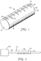
FIG. 1 is a perspective view of a segment of an elongate light guide; -
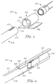
FIG. 2 is a schematic view of an elongate light guide assembly; -
FIG. 3 is an exploded perspective view of an illustrative light guide assembly; -
FIG. 4 is a cross-sectional view of the assembled light guide assembly shown inFIG. 3 ; -
FIG. 5 is a perspective view of an illustrative primary encoding orientation geometry; -
FIG. 6 is perspective view of the primary encoding orientation geometry shown inFIG. 5 coupled to an illustrative light source connector having secondary encoding orientation geometry; -
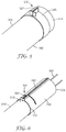
FIG. 7 is a perspective view of another illustrative light source connector having secondary encoding orientation geometry; and -
FIG. 8 and FIG. 9 are perspective views of a light guide assembly including the light source connector shown inFIG. 7 ; -
FIG. 10 is a perspective view of another illustrative light guide assembly. - The figures are not necessarily to scale. Like numbers used in the figures refer to like components. However, it will be understood that the use of a number to refer to a component in a given figure is not intended to limit the component in another figure labeled with the same number.
- In the following description, reference is made to the accompanying drawings that form a part hereof, and in which are shown by way of illustration several specific embodiments. It is to be understood that other embodiments are contemplated and may be made without departing from the scope or spirit of the present invention. The following detailed description, therefore, is not to be taken in a limiting sense.
- All scientific and technical terms used herein have meanings commonly used in the art unless otherwise specified. The definitions provided herein are to facilitate understanding of certain terms used frequently herein and are not meant to limit the scope of the present disclosure.
- Unless otherwise indicated, all numbers expressing feature sizes, amounts, and physical properties used in the specification and claims are to be understood as being modified in all instances by the term "about." Accordingly, unless indicated to the contrary, the numerical parameters set forth in the foregoing specification and attached claims are approximations that can vary depending upon the desired properties sought to be obtained by those skilled in the art utilizing the teachings disclosed herein.
- The recitation of numerical ranges by endpoints includes all numbers subsumed within that range (e.g. 1 to 5 includes 1, 1.5, 2, 2.75, 3, 3.80, 4, and 5) and any range within that range.
- As used in this specification and the appended claims, the singular forms "a", "an", and "the" encompass embodiments having plural referents, unless the content clearly dictates otherwise.
- The present disclosure relates to light guide orientation connectors and particularly to light guide connectors that provide illumination orientation of a connected light guide. These light guide illumination assemblies includes a radial illuminating light guide having encoding orientation geometry that corresponds to a light source connector orientation encoding geometry. The encoding orientation geometry provides an illumination assembly having a radial illumination from the light guide at a predetermined orientation to ensure that light is emitted in the proper radial direction from the elongate light guide relative to the light guide orientation connector. While the present invention is not so limited, an appreciation of various aspects of the invention will be gained through a discussion of the examples provided below.
- Light injected into an elongate light guide or light fiber propagates through the guide along an axis of propagation substantially coincident with the longitudinal axis of the elongate guide or fiber. The light propagates through the elongate guide or fiber with a maximum cone angle measured from the axis of propagation that is determined by the critical angle necessary for total internal reflection. The maximum cone angle can be derived by calculating the critical angle required for total internal reflection from Snell's law as is well known. The maximum cone angle is the complement of the critical angle. Light can be radially (along a length of the light guide) emitted from an elongate light guide by causing light to exceed the critical angle.
-
FIG. 1 is a perspective view of a segment of an illustrativeelongate light guide 20 for radial emission of light. Theelongate light guide 20 includes anelongate body 22 having a first end orlight input end 24, a second end ordistal end 26, and an opticallysmooth surface 28 extending longitudinally along the length of theelongate light guide 20. Theelongate light guide 20 can have a substantially cylindrical shape in certain embodiments. The opticallysmooth surface 28 propagates light along the length of theelongate light guide 20. In this embodiment, the opticallysmooth surface 28 corresponds to a circumferential surface of theelongate light guide 20. The optically smooth surface reflects light incident on the surface with minimal scattering or diffusion. One or more cladding layers (not shown) can be disposed about the optically smooth surface, as desired. - The
elongate light guide 20 includes a plurality oflight extraction structures elongate light guide 20. The plurality oflight extraction structures elongate light guide 20. In some embodiments, a first set oflight extraction structures 30 are centered about a firstlongitudinal axis 38 extending along the opticallyreflective surface 28 of theelongate light guide 20 and a second plurality oflight extraction structures 40 are centered about a secondlongitudinal axis 48 extending along the opticallyreflective surface 28 of theelongate light guide 20. The firstlongitudinal axis 38 can be adjacent to the secondlongitudinal axis 48. This arrangement oflight extraction structures U.S. Patent No. 5,845,038 . In other embodiments, thelight extraction structures longitudinal axis -
FIG. 2 is a schematic diagram view of an elongatelight guide assembly 110 utilizing the radial light emitting elongate light guide described inFIG. 1 . Thelight guide assembly 110 includes alight source assembly 112 coupled to an elongatelight guide 114. Thelight source assembly 112 includes a light source (not shown) capable of directing light into the elongatelight guide 114. The elongatelight guide 114 includes alight emitting region 116 extending along at least a portion of the elongatelight guide 114 length. Thelight emitting region 116 includes a plurality oflight extraction structures light guide 114, as described above. The plurality oflight extraction structures FIG. 2 and described in relation toFIG. 1 above. In some embodiments, thelight emitting region 116 extends along only a portion of thelight guide 114 length, as shown inFIG. 2 . The elongate light guides 114 described herein can be formed by any useful method such as, for example, molding or extrusion. - Elongate light guides are used for decorative and functional light purposes in various locations, some of which require the elongate light guide to emit light selectively along its length (e.g., radial emission). Elongate light guides of this type are often referred to as a linear lighting device. These linear lighting devices offer a number of advantages including, for example, the utilization of a low voltage light source such as an LED (light emitting diode) light source, and the ability to separate the light source from the illumination area.
- These linear lighting devices often need to support the elongate light guide in some manner to retain the required position of the light guide and ensure that light is radially emitted in the proper direction. These linear lighting devices have a defined light emitting region and are intended to provide a directed light. Thus, installing the elongate light guide in the correct orientation is important to achieving proper directional illumination. In certain situations, installing these elongate light guides properly is difficult since the location of the light emitting region of the elongate light guide is not always clearly apparent. Providing primary encoding orientation geometry on the light input end of their elongate light guides where the primary encoding orientation geometry is properly positioned relative to the light extraction structures and mates with secondary encoding geometry on a light source connector provides a convenient assembly to ensure that the defined light emitting region of the elongate light guide directs light in the proper direction.
-
FIG. 3 is an exploded perspective view of an illustrativelight guide assembly 200 andFIG. 4 is a cross-sectional view of the assembledlight guide assembly 200 shown inFIG. 3 . Thelight guide assembly 200 includes an elongate light guide 210 (described above) having alight input end 212 including a lightinput end surface 214, a distal end and a length therebetween. The elongatelight guide 210 has an opticallysmooth surface 216 for propagating light along the length and a light emitting region (116,FIG. 2 ) extending along at least a portion of the light guide length. The light emitting region includes a plurality of light extraction structures (118, 120,FIG. 2 ) extending into the elongate light guide to extract or reflect light radially from the elongate light guide, as described above. Thelight input end 212 includes primaryencoding orientation geometry 220. - The illustrated primary
encoding orientation geometry 220 includes a notch or a recess extending into a portion of the circumference of the elongatelight guide 210. The illustrated primaryencoding orientation geometry 220 notch or recess also extends into a portion of the light input end surface of the elongatelight guide 210. In some embodiments, the primaryencoding orientation geometry 220 includes a notch or a recess extending only into a portion of the circumference of the elongate light guide 210 (not shown). In other embodiments, the primaryencoding orientation geometry 220 includes a notch or a recess extending only into a portion of the light input end surface of the elongate light guide 210 (not shown). While a single notch or recess is shown, it is understood that the primaryencoding orientation geometry 220 can include two or more notches extending into a portion of the circumference of the elongatelight guide 210 and/or extending into a portion of the light input end surface of the elongatelight guide 210, as desired. - In some embodiments, the primary encoding geometry can include one, two or more protrusions (not shown) extending away from the circumference of the elongate light guide, in addition to, or replacing the one, two or more notch or recesses shown. In further embodiments, the primary encoding geometry can include one, two or more protrusions (not shown) extending away from the light input end surface of the elongate light guide, in addition to, or replacing the one, two or more notch or recesses shown. In many embodiments, the primary
encoding orientation geometry 220 is disposed only at thelight input end 212 of the elongatelight guide 210. In many embodiments, the primaryencoding orientation geometry 220 is separated from the plurality of light extraction structures (118, 120,FIG. 2 ). - A
light source connector 230 is coupled to thelight input end 212 of the elongatelight guide 210. Thelight source connector 230 includes afirst end 232 having secondaryencoding orientation geometry 240 and an opposingsecond end 234 configured to accept alight source 250. The secondaryencoding orientation geometry 240 mates with the primaryencoding orientation geometry 220. In the illustrated embodiment, thelight source connector 230first end 232 is disposed about the circumference of thelight input end 212 of the elongatelight guide 210. Thelight source connector 230 can include a mountingflange 236 to mount thelight guide assembly 200 to a mounting substrate (not shown). - The
light source 250 can be any usefullight source 250 for example, a solid state light source such as a light emitting diode. Light emitted by thelight source 250 is coupled into thelight input surface 214 of the elongatelight guide 210 and propagates along the length of the elongatelight guide 210 until it is radially emitted in the proper direction by the plurality of light extraction structures within the light emitting region of the elongatelight guide 210, as described above. Thus, thelight source connector 230 can be mounted on a substrate, the elongatelight guide 210 can be coupled to thelight source connector 230 via theorientation geometry orientation geometry orientation geometry light guide 210 and the mountedlight source connector 230. -
FIG. 5 is a perspective view of an illustrative primaryencoding orientation geometry 320 disposed on an elongatelight guide 310.FIG. 6 is perspective view of the primaryencoding orientation geometry 320 shown inFIG. 5 coupled to an illustrativelight source connector 330 having secondaryencoding orientation geometry 340. - The
light guide assembly 300 includes an elongate light guide 310 (described above) having alight input end 312 including a lightinput end surface 314, a distal end and a length therebetween. The elongatelight guide 310 has an opticallysmooth surface 316 for propagating light along the length and a light emitting region (116,FIG. 2 ) extending along at least a portion of the light guide length. The light emitting region includes a plurality of light extraction structures (118, 120,FIG. 2 ) extending into the elongate light guide to extract or reflect light radially from the elongate light guide, as described above. Thelight input end 312 includes primaryencoding orientation geometry 320. - The illustrated primary
encoding orientation geometry 320 is acollar 325 disposed about the circumference of the elongatelight guide 310light input end 312. The illustrated primaryencoding orientation geometry 320 includes aprotrusion 327 that extends away from thecollar 325. Thecollar 325 can be formed of any useful material such as a polymer and/or a metal. In some embodiments, thecollar 325 is formed of a metallic material and the elongate light guide 310 a polymeric material. Thecollar 325 can be crimped or otherwise fixed to the circumference of the elongatelight guide 310light input end 312 and the primaryencoding orientation geometry 320 position about the circumference of the elongatelight guide 310light input end 312 is set relative to the location of the light extraction structures extending into the elongate light guide, described above. While asingle protrusion 327 is shown, it is understood that the primaryencoding orientation geometry 320 can include two or more protrusions extending away from thecollar 325. In many embodiments, the primaryencoding orientation geometry 320 is disposed only at thelight input end 312 of the elongatelight guide 310. In many embodiments, the primaryencoding orientation geometry 320 is separated from the plurality of light extraction structures (118, 120,FIG. 2 ). - A
light source connector 330 is coupled to thelight input end 312 of the elongatelight guide 310. Thelight source connector 330 includes afirst end 332 having secondaryencoding orientation geometry 340 and an opposingsecond end 334 configured to accept alight source 350. The secondaryencoding orientation geometry 340 mates with the primaryencoding orientation geometry 320. In the illustrated embodiment, thelight source connector 330first end 332 is disposed about the circumference of thelight input end 312 of the elongatelight guide 310 and is disposed about thecollar 325. Thelight source connector 330 can include a mounting flange (not shown) to mount thelight guide assembly 300 to a mounting substrate (not shown). - The
collar 325 does not affect the cross-sectional area of the elongatelight guide 310. Thus, light propagating through the elongatelight guide 310 is not affected by the primaryencoding orientation geometry 320. In addition, thecollar 325 provides a convenient primaryencoding orientation geometry 320 since the collar can be applied to an elongate light guide and then the elongate light guide can be further processed by, for example, cutting the elongate light guide to a desired length. Then the cut elongate light guide can be assembled into the final light guide assembly. - The
light source 350 can be any usefullight source 350, as described above. Light emitted by thelight source 350 is coupled into thelight input surface 314 of the elongatelight guide 310 and propagates along the length of the elongatelight guide 310 until it is radially emitted in the proper direction by the plurality of light extraction structures within the light emitting region of the elongatelight guide 310. Thus, thelight source connector 330 can be mounted on a substrate, the elongatelight guide 310 can be coupled to thelight source connector 330 via theorientation geometry orientation geometry orientation geometry light guide 310 and the mountedlight source connector 330. -
FIG. 7 is a perspective view of another illustrativelight source connector 430 having secondaryencoding orientation geometry 440.FIG. 8 and FIG. 9 are perspective views of alight guide assembly 400 including thelight source connector 430 shown inFIG. 7 . - The
light guide assembly 400 includes an elongate light guide 410 (described above) having alight input end 412 including a lightinput end surface 414, a distal end and a length therebetween. The elongatelight guide 410 has an opticallysmooth surface 416 for propagating light along the length and a light emitting region (116,FIG. 2 ) extending along at least a portion of the light guide length. The light emitting region includes a plurality oflight extraction structures 418 extending into the elongate light guide to extract or reflect light radially from the elongatelight guide 410, as described above. Thelight input end 412 includes primaryencoding orientation geometry 420, as described above. - The illustrated primary
encoding orientation geometry 420 includes a protrusion extending away from the circumference of the elongatelight guide 410. The illustrated primaryencoding orientation geometry 420 protrusion may also extend into a portion of the lightinput end surface 414 of the elongatelight guide 410. The primaryencoding orientation geometry 420 can be any of the embodiments described herein. - A hinged
light source connector 430 is disposed about the circumference of the elongatelight guide 410light input end 412. Thelight source connector 430 includes afirst end 432 having secondaryencoding orientation geometry 440 and an opposingsecond end 434 configured to accept a light source 450. The secondaryencoding orientation geometry 440 mates with the primaryencoding orientation geometry 420. Thelight source connector 430 includes lightguide holding ribs 438 to hold the elongate light guide within thelight source connector 430. - The hinged
light source connector 430 includes aliving hinge 439 at thesecond end 434. The elongatelight guide 410light input end 412 is placed within the hingedlight source connector 430 and theencoding orientation geometry light source connector 430 is closed about the elongatelight guide 410light input end 412 to secure the elongatelight guide 410 within the hingedlight source connector 430. The hingedlight source connector 430 includes a mounting flange or mountingtabs 436 that mate with mountingtabs 452 on alight source housing 454. The hingedlight source connector 430 is disposed within anaperture 455 formed by thelight source housing 454. - A light source (not shown) is disposed within the
light source housing 454 and is adjacent to thelight input surface 414 of the elongatelight guide 410.Base tabs 456 are disposed on thelight source housing 454 and are configured to clip into retainingclips 470 of a base substrate. In many embodiments, the base substrate is a flat cable providing power to the light source disposed within thelight source housing 454. The light source can be any useful light source, as described above. Light emitted by the light source is coupled into thelight input surface 414 of the elongatelight guide 410 and propagates along the length of the elongatelight guide 410 until it is radially emitted in the proper direction by the plurality oflight extraction structures 418 within the light emitting region of the elongatelight guide 410. Thus, thelight source connector 430 can be mounted to thelight source housing 454 which is mounted to a base substrate, and the elongatelight guide 410 can be coupled to thelight source connector 430 via theorientation geometry orientation geometry orientation geometry light guide 410 and the mountedlight source connector 430. -
FIG. 10 is a perspective view of another illustrativelight guide assembly 500. Thelight guide assembly 500 includes an elongate light guide 510 (described above) having alight input end 512 including a lightinput end surface 514, a distal end and a length therebetween. The elongatelight guide 510 has an opticallysmooth surface 516 for propagating light along the length and a light emitting region (116,FIG. 2 ) extending along at least a portion of the light guide length. The light emitting region includes a plurality of light extraction structures (118, 120,FIG. 2 ) extending into the elongate light guide to extract or reflect light radially from the elongate light guide. Thelight input end 512 includes primaryencoding orientation geometry 520. - The illustrated primary
encoding orientation geometry 520 is a recess into or a protrusion away from thelight input surface 514 and forming thelight input surface 514. The illustrated primaryencoding orientation geometry 520 can also be described as a hemispherical notch or hemispherical step forming thelight input surface 514. The primaryencoding orientation geometry 520 is disposed within the circumference of thelight input end 512 of the elongatelight guide 510. The primaryencoding orientation geometry 520 is formed of the same material that formed the elongatelight guide 510. In many embodiments, the primaryencoding orientation geometry 520 and the elongatelight guide 510 form a unitary body. The primaryencoding orientation geometry 520 and the elongatelight guide 510 can be formed of a solid material such as a polymeric material, glass, and the like. - A
light source connector 530 is coupled to thelight input end 512 of the elongatelight guide 510. Thelight source connector 530 includes afirst end 532 having secondaryencoding orientation geometry 540 and an opposingsecond end 534 configured to accept alight source 550. Thesecondary encoding orientation 540 geometry mates with the primaryencoding orientation geometry 520. The illustrated secondaryencoding orientation geometry 540 can be described as a hemispherical notch or hemispherical step forming a light output surface that mates with thelight input surface 514. - In the illustrated embodiment, the
light source connector 530first end 532 is in contact with thelight input surface 514 of the elongatelight guide 510. Thelight source connector 530first end 532 circumference is equal to or less than the circumference of thelight input end 512 of the elongatelight guide 510. In the illustrated embodiment, thesecondary encoding orientation 540 geometry and the mating primaryencoding orientation geometry 520 are disposed within the circumference of thelight input end 512 of the elongatelight guide 510. The illustratedlight source connector 530 is a solid body formed of a polymeric or glass material and includes a recess configured to accept thelight source 550. In many embodiments, thelight source connector 530 solid body material and the elongatelight guide 510 solid body material both have a substantially equal refractive index. In many embodiments, thelight source connector 530 is fixed to the elongatelight guide 510 with an adhesive. Thelight source connector 530 can include a mountingflange 536 to mount thelight guide assembly 500 to a mounting substrate (not shown). - When the
light source connector 530 solid body material and the elongatelight guide 510 solid body material have substantially similar refractive indices and are optically coupled with an appropriate adhesive, liquid or gel, theencoding orientation geometry light guide 510. Thus, light propagating through the elongatelight guide 510 is not affected by theencoding orientation geometry - The
light source 550 can be any usefullight source 550, as described above. Light emitted by thelight source 550 is coupled into thelight input surface 514 of the elongatelight guide 510 and propagates along the length of the elongatelight guide 510 until it is radially emitted in the proper direction by the plurality of light extraction structures within the light emitting region of the elongatelight guide 510. Thus, thelight source connector 530 can be mounted on a substrate, the elongatelight guide 510 can be coupled to thelight source connector 530 via theorientation geometry orientation geometry orientation geometry light guide 510 and the mountedlight source connector 530. - The light guide assemblies described herein can be formed by providing an elongate light guide, described above, forming primary encoding orientation geometry on the light input end of the elongate light guide, providing a light source connector having secondary encoding orientation geometry where the secondary encoding orientation geometry mates with the primary encoding geometry, and coupling the light source connector secondary encoding orientation geometry to the elongate light guide primary encoding orientation geometry, to form a light guide assembly.
- Thus, embodiments of a LIGHTGUIDE ORIENTATION CONNECTOR are disclosed. One skilled in the art will appreciate that embodiments other than those disclosed are envisioned. The disclosed embodiments are presented for purposes of illustration and not limitation, and the present invention should be limited only by the claims.
Claims (11)
- A light guide assembly (110; 200; 300; 400; 500) comprising;
an elongate light guide (20; 114; 210; 310; 410; 510) having a light input end (24; 212; 312; 412; 512) including a light input end surface, a distal end (26) and a length therebetween, the elongate light guide having an optically smooth surface (28; 216; 316; 416; 516) for propagating light along the length and a light emitting region (116) extending along at least a portion of the light guide length, the light emitting region comprising a plurality of light extraction structures (30, 40; 118, 120; 418) extending into the elongate light guide to extract or reflect light radially from the elongate light guide, the light input end comprising primary encoding orientation geometry (220; 320; 420; 520); and
a light source connector (230; 330; 430; 530) coupled to the light input end of
the elongate light guide, the light source connector comprising a first end having secondary encoding orientation geometry (240; 340; 440; 540) and an opposing second end configured to accept a light source, wherein the secondary encoding orientation geometry (240; 340; 440; 540) mates with the primary encoding orientation geometry (220; 320; 420; 520);
wherein the primary encoding orientation geometry (220; 320; 420; 520)
comprises
a collar element (325) disposed about an exterior circumference of the
elongate light guide and fixed to the circumference of the elongate light guide, and
an outwardly extending protrusion (327) extending away from the collar
element (325). - A light guide assembly (110; 200; 300; 400; 500) comprising;
an elongate light guide (20; 114; 210; 310; 410; 510) having a light input end (24; 212; 312; 412; 512) including a light input end surface, a distal end (26) and a length therebetween, the elongate light guide having an optically smooth surface (28; 216; 316; 416; 516) for propagating light along the length and a light emitting region extending along at least a portion of the light guide length, the light emitting region comprising a plurality of light extraction structures (30, 40; 118, 120; 418) extending into the elongate light guide to extract or reflect light radially from the elongate light guide, the light input end comprising primary encoding orientation geometry (220; 320; 420; 520); and
a light source connector (230; 330; 430; 530) coupled to the light input end of
the elongate light guide, the light source connector comprising a first end having secondary encoding orientation geometry (240; 340; 440; 540) and an opposing second end configured to accept a light source, wherein the secondary encoding orientation geometry (240; 340; 440; 540) mates with the primary encoding orientation geometry (220; 320; 420; 520);
wherein the primary encoding orientation geometry (220; 320; 420; 520)
comprises a recess extending into a portion of the circumference of the elongate light guide; and
wherein the secondary encoding orientation geometry mates (240; 340; 440; 540) with the recess. - A light guide assembly according to claim 1 or 2, further comprising a light source adjacent to the light input end surface, the light source comprising a solid state light source.
- A light guide assembly according to claim 1 or 2, wherein the light guide comprises a polymeric material.
- A light guide assembly according to claim 1 or 2, wherein the light source connector (230; 330; 430; 530) is disposed about a circumference of the elongate light guide.
- A light guide assembly according to claim 1 or 2, wherein the light source connector first end has a circumference equal to or less than a circumference of the elongate light guide light input end.
- A light guide assembly according to claim 1 or 2, wherein the light source connector (230; 330; 430; 530) further includes a mounting flange.
- A light guide assembly according to claim 1 or 2, wherein the light source connector and the light guide are solid bodies, and the light source connector and the light guide have a refractive index that is substantially equal.
- A light guide assembly according to claim 1 or 2, wherein the elongate light guide is substantially cylindrical.
- A method of forming a light guide assembly (110; 200; 300; 400; 500) comprising;
providing an elongate light guide (20; 114; 210; 310; 410; 510) having a light
input end including a light input end surface, a distal end and a light guide length therebetween, the elongate light guide having an optically smooth surface for propagating light along the guide length and a light emitting region extending along at least a portion of the guide length, the light emitting region comprising a plurality of light extraction structures extending into the elongate light guide to extract or reflect light radially from the elongate light guide;
forming primary encoding orientation geometry (220; 320; 420; 520) on the
light input end of the elongate light guide, the primary encoding orientation geometry (220; 320; 420; 520) comprising a collar element (325) disposed about an exterior circumference of the elongate light guide and fixed to the circumference of the elongate light guide,
an outwardly extending protrusion extending away from the collar
element;
providing a light source connector (230; 330; 430; 530) comprising a first end
having secondary encoding orientation geometry (240; 340; 440; 540) and an opposing second end configured to accept a light source; and coupling the light source connector secondary encoding orientation geometry (240; 340; 440; 540) to the elongate light guide primary encoding orientation geometry (220; 320; 420; 520), to form a light guide assembly. - A method according to claim 10, further comprising disposing a solid state light source within the second end of the light source connector.
Applications Claiming Priority (2)
| Application Number | Priority Date | Filing Date | Title |
|---|---|---|---|
| US11/676,676 US7677780B2 (en) | 2007-02-20 | 2007-02-20 | Light guide orientation connector |
| PCT/US2008/052181 WO2008103522A1 (en) | 2007-02-20 | 2008-01-28 | Light guide orientation connector |
Publications (3)
| Publication Number | Publication Date |
|---|---|
| EP2115510A1 EP2115510A1 (en) | 2009-11-11 |
| EP2115510A4 EP2115510A4 (en) | 2011-04-06 |
| EP2115510B1 true EP2115510B1 (en) | 2016-08-24 |
Family
ID=39706499
Family Applications (1)
| Application Number | Title | Priority Date | Filing Date |
|---|---|---|---|
| EP08728376.8A Not-in-force EP2115510B1 (en) | 2007-02-20 | 2008-01-28 | Light guide orientation connector |
Country Status (7)
| Country | Link |
|---|---|
| US (1) | US7677780B2 (en) |
| EP (1) | EP2115510B1 (en) |
| JP (1) | JP5421128B2 (en) |
| KR (1) | KR101450933B1 (en) |
| CN (1) | CN101617258B (en) |
| TW (1) | TWI467259B (en) |
| WO (1) | WO2008103522A1 (en) |
Families Citing this family (16)
| Publication number | Priority date | Publication date | Assignee | Title |
|---|---|---|---|---|
| EP2395738B1 (en) * | 2007-07-31 | 2016-03-23 | Samsung Electronics Co., Ltd. | Multi-functional device having scanner module and image scanning apparatus employing the scanner module |
| US8379275B2 (en) | 2007-07-31 | 2013-02-19 | Samsung Electronics Co., Ltd. | Scanner module and image scanning apparatus employing the same |
| US8358447B2 (en) | 2007-07-31 | 2013-01-22 | Samsung Electronics Co., Ltd. | Scanner module and image scanning apparatus employing the same |
| JP5643750B2 (en) | 2008-04-30 | 2014-12-17 | スリーエム イノベイティブ プロパティズ カンパニー | Illumination system and light injection coupler therefor |
| KR101406891B1 (en) * | 2008-06-18 | 2014-06-13 | 삼성디스플레이 주식회사 | Display apparatus |
| EP2302294A1 (en) * | 2009-09-18 | 2011-03-30 | 3M Innovative Properties Company | Connector |
| EP2372414A1 (en) * | 2010-03-11 | 2011-10-05 | 3M Innovative Properties Company | Multiple side-light guides having a single light source |
| JP5620222B2 (en) * | 2010-10-18 | 2014-11-05 | テイ・エス テック株式会社 | Light emitting device |
| US9657907B2 (en) * | 2010-12-14 | 2017-05-23 | Bridgelux Inc. | Side light LED troffer tube |
| US9308051B2 (en) | 2011-11-15 | 2016-04-12 | Smiths Medical Asd, Inc. | Illuminated tubing set |
| US9308323B2 (en) | 2011-11-15 | 2016-04-12 | Smiths Medical Asd, Inc. | Systems and methods for illuminated medical tubing detection and management indicating a characteristic of at least one infusion pump |
| CZ306764B6 (en) * | 2013-09-30 | 2017-06-21 | Varroc Lighting Systems, s.r.o. | A lighting device |
| US10384598B2 (en) * | 2016-08-15 | 2019-08-20 | Ford Global Technologies, Llc | Vehicle ambient light system employing a light guide |
| DE102016122585B4 (en) * | 2016-11-23 | 2018-07-12 | Preh Gmbh | Turntable with improved, optical rotary position detection |
| KR102141649B1 (en) * | 2019-03-06 | 2020-08-05 | 주식회사 케이티앤지 | A fixture including a light guide portion and an aerosol generating device including the same |
| EP3812814A1 (en) * | 2019-10-23 | 2021-04-28 | Volvo Car Corporation | An improved housing for coupling of light from a light source to an optical light guide |
Family Cites Families (37)
| Publication number | Priority date | Publication date | Assignee | Title |
|---|---|---|---|---|
| FR2459555A1 (en) | 1979-06-20 | 1981-01-09 | Radiotechnique Compelec | LIGHT EMITTING DEVICE FOR OPTICAL FIBER TRANSMISSION |
| JPH02143202A (en) | 1988-11-25 | 1990-06-01 | Takashi Mori | Optical radiator |
| DE3902807C1 (en) * | 1989-01-31 | 1990-08-09 | Messerschmitt-Boelkow-Blohm Gmbh, 8012 Ottobrunn, De | |
| US5086378A (en) * | 1990-08-20 | 1992-02-04 | Prince Mark W | Fiber optic finger light |
| JP3174134B2 (en) | 1992-04-28 | 2001-06-11 | オリンパス光学工業株式会社 | Endoscope |
| US5432876C1 (en) * | 1992-10-19 | 2002-05-21 | Minnesota Mining & Mfg | Illumination devices and optical fibres for use therein |
| US5450293A (en) * | 1993-12-30 | 1995-09-12 | Hoffman; Elliott S. | Finger mounted fiber optic illumination system |
| WO1997026573A1 (en) * | 1996-01-19 | 1997-07-24 | Lumenyte International Corporation | Side lighting optical conduit |
| US5680496A (en) * | 1996-10-18 | 1997-10-21 | American Products, Inc. | Fiber optic cable assembly for perimeter lighting |
| US5857758A (en) | 1996-12-17 | 1999-01-12 | Transmatic, Inc. | Lighting system for mass-transit vehicles |
| US5845038A (en) * | 1997-01-28 | 1998-12-01 | Minnesota Mining And Manufacturing Company | Optical fiber illumination system |
| US6863428B2 (en) * | 1997-10-24 | 2005-03-08 | 3M Innovative Properties Company | Light guide illumination device appearing uniform in brightness along its length |
| US6077462A (en) * | 1998-02-20 | 2000-06-20 | 3M Innovative Properties Company | Method and apparatus for seamless microreplication using an expandable mold |
| US6275644B1 (en) | 1998-12-15 | 2001-08-14 | Transmatic, Inc. | Light fixture including light pipe having contoured cross-section |
| US6302570B1 (en) * | 1999-10-14 | 2001-10-16 | Fiber Optic Design, Inc. | Compact illumination device using optical fibers |
| US6626582B2 (en) * | 2000-02-17 | 2003-09-30 | Cogent Light Technologies, Inc. | Snap-on connector system for coupling light from an illuminator to a fiber optic |
| JP3784601B2 (en) * | 2000-02-28 | 2006-06-14 | アルプス電気株式会社 | Optical fiber connector and optical communication module using the same |
| US6418252B1 (en) * | 2001-01-16 | 2002-07-09 | The Regents Of The University Of California | Light diffusing fiber optic chamber |
| US6623667B2 (en) * | 2001-02-28 | 2003-09-23 | 3M Innovative Properties Company | Method for continuous fabrication of structured surface light guides |
| US20030063888A1 (en) * | 2001-10-01 | 2003-04-03 | Sahlin Jennifer J. | Channeling for use with light fiber |
| JP4097927B2 (en) * | 2001-11-01 | 2008-06-11 | 株式会社小糸製作所 | Vehicle lamp |
| US6866427B2 (en) * | 2001-11-13 | 2005-03-15 | Lumenyte International Corporation | Fiber optic LED light |
| US6827468B2 (en) * | 2001-12-10 | 2004-12-07 | Robert D. Galli | LED lighting assembly |
| JP2003325449A (en) * | 2002-05-15 | 2003-11-18 | Fuji Photo Optical Co Ltd | Connection structure for light source connector for endoscope to light source device |
| US6763172B2 (en) * | 2002-05-16 | 2004-07-13 | 3M Innovative Properties Company | Support clip for use with light fiber |
| US7021809B2 (en) * | 2002-08-01 | 2006-04-04 | Toyoda Gosei Co., Ltd. | Linear luminous body and linear luminous structure |
| US6758588B2 (en) * | 2002-08-06 | 2004-07-06 | American Auto Accessories | Optical fiber light |
| US6883949B2 (en) * | 2002-09-17 | 2005-04-26 | Tyco Electronics Canada Ltd. | Apparatus, method and article of manufacture for a light pipe and lamp assembly |
| US6910795B2 (en) * | 2003-04-18 | 2005-06-28 | Tyco Electronics Canada, Ltd. | Overmolded low voltage lamp assembly |
| JP4388790B2 (en) * | 2003-11-06 | 2009-12-24 | 富士フイルム株式会社 | Endoscope light source device socket |
| TWM253779U (en) * | 2003-12-19 | 2004-12-21 | Hon Hai Prec Ind Co Ltd | Optical fiber connector |
| TWM250162U (en) * | 2004-01-19 | 2004-11-11 | Jin-Ru Liou | Optical connector of multi-core optical fiber |
| US7404680B2 (en) | 2004-05-31 | 2008-07-29 | Ngk Spark Plug Co., Ltd. | Optical module, optical module substrate and optical coupling structure |
| JP4314157B2 (en) * | 2004-06-07 | 2009-08-12 | 三菱電機株式会社 | Planar light source device and display device using the same |
| JP4544928B2 (en) * | 2004-07-16 | 2010-09-15 | スリーエム イノベイティブ プロパティズ カンパニー | Optical connector and optical fiber connection system |
| US7090529B1 (en) * | 2005-09-10 | 2006-08-15 | Xiao-Ping Wang | LED connector |
| GB0615854D0 (en) | 2006-08-10 | 2006-09-20 | 3M Innovative Properties Co | Light guide for a lighting device |
-
2007
- 2007-02-20 US US11/676,676 patent/US7677780B2/en not_active Expired - Fee Related
-
2008
- 2008-01-28 CN CN2008800056334A patent/CN101617258B/en not_active Expired - Fee Related
- 2008-01-28 JP JP2009550100A patent/JP5421128B2/en not_active Expired - Fee Related
- 2008-01-28 KR KR1020097019486A patent/KR101450933B1/en not_active IP Right Cessation
- 2008-01-28 EP EP08728376.8A patent/EP2115510B1/en not_active Not-in-force
- 2008-01-28 WO PCT/US2008/052181 patent/WO2008103522A1/en active Application Filing
- 2008-02-19 TW TW97105747A patent/TWI467259B/en not_active IP Right Cessation
Also Published As
| Publication number | Publication date |
|---|---|
| JP5421128B2 (en) | 2014-02-19 |
| EP2115510A4 (en) | 2011-04-06 |
| TWI467259B (en) | 2015-01-01 |
| JP2010519689A (en) | 2010-06-03 |
| TW200848821A (en) | 2008-12-16 |
| CN101617258A (en) | 2009-12-30 |
| KR101450933B1 (en) | 2014-10-14 |
| KR20090114461A (en) | 2009-11-03 |
| EP2115510A1 (en) | 2009-11-11 |
| CN101617258B (en) | 2011-04-20 |
| US7677780B2 (en) | 2010-03-16 |
| US20080198624A1 (en) | 2008-08-21 |
| WO2008103522A1 (en) | 2008-08-28 |
Similar Documents
| Publication | Publication Date | Title |
|---|---|---|
| EP2115510B1 (en) | Light guide orientation connector | |
| EP3137933B1 (en) | Optical connectors for coupling light sources to optical fibers | |
| US7104702B2 (en) | Field installable optical fiber connector | |
| US20050213892A1 (en) | Field installable optical fiber connector | |
| US6137928A (en) | Optical fiber light distribution system and method of manufacture and illumination | |
| CN105723150A (en) | Light guide illumination device with light divergence modifier | |
| KR20060090579A (en) | Optical fiber connector component and optical fiber connector using same | |
| WO2009030982A2 (en) | Optical ferrule assembly | |
| US10838137B2 (en) | Lighting device with high efficiency and uniformity | |
| KR100254086B1 (en) | Optical fiber connector | |
| US5009479A (en) | Optical fiber coupling device and method for its use | |
| KR100309119B1 (en) | Optical fiber connection device | |
| JP2949077B2 (en) | Optical fiber cable connector | |
| JP5543293B2 (en) | Small-diameter bending optical connector | |
| US20040146251A1 (en) | Optical connector | |
| US6561700B1 (en) | Fiber optic cable splice apparatus and method | |
| US6425696B1 (en) | Molded fiber optic ferrule receptable | |
| US9340151B2 (en) | Optical coupler for vehicle lighting systems | |
| CN116774362A (en) | Ferrule, optical connector and optical connector module | |
| JP2000162476A (en) | Module for optical communication | |
| WO2016205306A2 (en) | Optical coupling systems for optically coupling laser diodes to optical fibers | |
| JP2000076917A (en) | Lighting system | |
| EP1005660A1 (en) | Optical fiber light distribution system and method of manufacture and illumination | |
| EP1781985A1 (en) | Luminous blongate device with a light fibre and a ight injector |
Legal Events
| Date | Code | Title | Description |
|---|---|---|---|
| PUAI | Public reference made under article 153(3) epc to a published international application that has entered the european phase |
Free format text: ORIGINAL CODE: 0009012 |
|
| 17P | Request for examination filed |
Effective date: 20090831 |
|
| AK | Designated contracting states |
Kind code of ref document: A1 Designated state(s): AT BE BG CH CY CZ DE DK EE ES FI FR GB GR HR HU IE IS IT LI LT LU LV MC MT NL NO PL PT RO SE SI SK TR |
|
| DAX | Request for extension of the european patent (deleted) | ||
| A4 | Supplementary search report drawn up and despatched |
Effective date: 20110309 |
|
| 17Q | First examination report despatched |
Effective date: 20120118 |
|
| GRAP | Despatch of communication of intention to grant a patent |
Free format text: ORIGINAL CODE: EPIDOSNIGR1 |
|
| RIC1 | Information provided on ipc code assigned before grant |
Ipc: G02B 6/42 20060101AFI20160216BHEP Ipc: F21V 8/00 20060101ALI20160216BHEP |
|
| INTG | Intention to grant announced |
Effective date: 20160310 |
|
| GRAS | Grant fee paid |
Free format text: ORIGINAL CODE: EPIDOSNIGR3 |
|
| GRAA | (expected) grant |
Free format text: ORIGINAL CODE: 0009210 |
|
| AK | Designated contracting states |
Kind code of ref document: B1 Designated state(s): AT BE BG CH CY CZ DE DK EE ES FI FR GB GR HR HU IE IS IT LI LT LU LV MC MT NL NO PL PT RO SE SI SK TR |
|
| REG | Reference to a national code |
Ref country code: GB Ref legal event code: FG4D |
|
| REG | Reference to a national code |
Ref country code: CH Ref legal event code: EP |
|
| REG | Reference to a national code |
Ref country code: AT Ref legal event code: REF Ref document number: 823582 Country of ref document: AT Kind code of ref document: T Effective date: 20160915 |
|
| REG | Reference to a national code |
Ref country code: IE Ref legal event code: FG4D |
|
| REG | Reference to a national code |
Ref country code: DE Ref legal event code: R096 Ref document number: 602008045860 Country of ref document: DE |
|
| REG | Reference to a national code |
Ref country code: FR Ref legal event code: PLFP Year of fee payment: 10 |
|
| REG | Reference to a national code |
Ref country code: LT Ref legal event code: MG4D |
|
| REG | Reference to a national code |
Ref country code: NL Ref legal event code: MP Effective date: 20160824 |
|
| REG | Reference to a national code |
Ref country code: AT Ref legal event code: MK05 Ref document number: 823582 Country of ref document: AT Kind code of ref document: T Effective date: 20160824 |
|
| PG25 | Lapsed in a contracting state [announced via postgrant information from national office to epo] |
Ref country code: NL Free format text: LAPSE BECAUSE OF FAILURE TO SUBMIT A TRANSLATION OF THE DESCRIPTION OR TO PAY THE FEE WITHIN THE PRESCRIBED TIME-LIMIT Effective date: 20160824 Ref country code: FI Free format text: LAPSE BECAUSE OF FAILURE TO SUBMIT A TRANSLATION OF THE DESCRIPTION OR TO PAY THE FEE WITHIN THE PRESCRIBED TIME-LIMIT Effective date: 20160824 Ref country code: HR Free format text: LAPSE BECAUSE OF FAILURE TO SUBMIT A TRANSLATION OF THE DESCRIPTION OR TO PAY THE FEE WITHIN THE PRESCRIBED TIME-LIMIT Effective date: 20160824 Ref country code: NO Free format text: LAPSE BECAUSE OF FAILURE TO SUBMIT A TRANSLATION OF THE DESCRIPTION OR TO PAY THE FEE WITHIN THE PRESCRIBED TIME-LIMIT Effective date: 20161124 Ref country code: LT Free format text: LAPSE BECAUSE OF FAILURE TO SUBMIT A TRANSLATION OF THE DESCRIPTION OR TO PAY THE FEE WITHIN THE PRESCRIBED TIME-LIMIT Effective date: 20160824 Ref country code: IT Free format text: LAPSE BECAUSE OF FAILURE TO SUBMIT A TRANSLATION OF THE DESCRIPTION OR TO PAY THE FEE WITHIN THE PRESCRIBED TIME-LIMIT Effective date: 20160824 |
|
| PG25 | Lapsed in a contracting state [announced via postgrant information from national office to epo] |
Ref country code: PT Free format text: LAPSE BECAUSE OF FAILURE TO SUBMIT A TRANSLATION OF THE DESCRIPTION OR TO PAY THE FEE WITHIN THE PRESCRIBED TIME-LIMIT Effective date: 20161226 Ref country code: GR Free format text: LAPSE BECAUSE OF FAILURE TO SUBMIT A TRANSLATION OF THE DESCRIPTION OR TO PAY THE FEE WITHIN THE PRESCRIBED TIME-LIMIT Effective date: 20161125 Ref country code: SE Free format text: LAPSE BECAUSE OF FAILURE TO SUBMIT A TRANSLATION OF THE DESCRIPTION OR TO PAY THE FEE WITHIN THE PRESCRIBED TIME-LIMIT Effective date: 20160824 Ref country code: ES Free format text: LAPSE BECAUSE OF FAILURE TO SUBMIT A TRANSLATION OF THE DESCRIPTION OR TO PAY THE FEE WITHIN THE PRESCRIBED TIME-LIMIT Effective date: 20160824 Ref country code: AT Free format text: LAPSE BECAUSE OF FAILURE TO SUBMIT A TRANSLATION OF THE DESCRIPTION OR TO PAY THE FEE WITHIN THE PRESCRIBED TIME-LIMIT Effective date: 20160824 Ref country code: LV Free format text: LAPSE BECAUSE OF FAILURE TO SUBMIT A TRANSLATION OF THE DESCRIPTION OR TO PAY THE FEE WITHIN THE PRESCRIBED TIME-LIMIT Effective date: 20160824 |
|
| PG25 | Lapsed in a contracting state [announced via postgrant information from national office to epo] |
Ref country code: RO Free format text: LAPSE BECAUSE OF FAILURE TO SUBMIT A TRANSLATION OF THE DESCRIPTION OR TO PAY THE FEE WITHIN THE PRESCRIBED TIME-LIMIT Effective date: 20160824 Ref country code: EE Free format text: LAPSE BECAUSE OF FAILURE TO SUBMIT A TRANSLATION OF THE DESCRIPTION OR TO PAY THE FEE WITHIN THE PRESCRIBED TIME-LIMIT Effective date: 20160824 |
|
| REG | Reference to a national code |
Ref country code: DE Ref legal event code: R097 Ref document number: 602008045860 Country of ref document: DE |
|
| PG25 | Lapsed in a contracting state [announced via postgrant information from national office to epo] |
Ref country code: PL Free format text: LAPSE BECAUSE OF FAILURE TO SUBMIT A TRANSLATION OF THE DESCRIPTION OR TO PAY THE FEE WITHIN THE PRESCRIBED TIME-LIMIT Effective date: 20160824 Ref country code: BE Free format text: LAPSE BECAUSE OF FAILURE TO SUBMIT A TRANSLATION OF THE DESCRIPTION OR TO PAY THE FEE WITHIN THE PRESCRIBED TIME-LIMIT Effective date: 20160824 Ref country code: DK Free format text: LAPSE BECAUSE OF FAILURE TO SUBMIT A TRANSLATION OF THE DESCRIPTION OR TO PAY THE FEE WITHIN THE PRESCRIBED TIME-LIMIT Effective date: 20160824 Ref country code: CZ Free format text: LAPSE BECAUSE OF FAILURE TO SUBMIT A TRANSLATION OF THE DESCRIPTION OR TO PAY THE FEE WITHIN THE PRESCRIBED TIME-LIMIT Effective date: 20160824 Ref country code: BG Free format text: LAPSE BECAUSE OF FAILURE TO SUBMIT A TRANSLATION OF THE DESCRIPTION OR TO PAY THE FEE WITHIN THE PRESCRIBED TIME-LIMIT Effective date: 20161124 Ref country code: SK Free format text: LAPSE BECAUSE OF FAILURE TO SUBMIT A TRANSLATION OF THE DESCRIPTION OR TO PAY THE FEE WITHIN THE PRESCRIBED TIME-LIMIT Effective date: 20160824 |
|
| PLBE | No opposition filed within time limit |
Free format text: ORIGINAL CODE: 0009261 |
|
| STAA | Information on the status of an ep patent application or granted ep patent |
Free format text: STATUS: NO OPPOSITION FILED WITHIN TIME LIMIT |
|
| 26N | No opposition filed |
Effective date: 20170526 |
|
| PG25 | Lapsed in a contracting state [announced via postgrant information from national office to epo] |
Ref country code: SI Free format text: LAPSE BECAUSE OF FAILURE TO SUBMIT A TRANSLATION OF THE DESCRIPTION OR TO PAY THE FEE WITHIN THE PRESCRIBED TIME-LIMIT Effective date: 20160824 |
|
| REG | Reference to a national code |
Ref country code: CH Ref legal event code: PL |
|
| GBPC | Gb: european patent ceased through non-payment of renewal fee |
Effective date: 20170128 |
|
| PG25 | Lapsed in a contracting state [announced via postgrant information from national office to epo] |
Ref country code: MC Free format text: LAPSE BECAUSE OF FAILURE TO SUBMIT A TRANSLATION OF THE DESCRIPTION OR TO PAY THE FEE WITHIN THE PRESCRIBED TIME-LIMIT Effective date: 20160824 |
|
| PG25 | Lapsed in a contracting state [announced via postgrant information from national office to epo] |
Ref country code: LI Free format text: LAPSE BECAUSE OF NON-PAYMENT OF DUE FEES Effective date: 20170131 Ref country code: CH Free format text: LAPSE BECAUSE OF NON-PAYMENT OF DUE FEES Effective date: 20170131 |
|
| REG | Reference to a national code |
Ref country code: IE Ref legal event code: MM4A |
|
| PG25 | Lapsed in a contracting state [announced via postgrant information from national office to epo] |
Ref country code: LU Free format text: LAPSE BECAUSE OF NON-PAYMENT OF DUE FEES Effective date: 20170128 Ref country code: GB Free format text: LAPSE BECAUSE OF NON-PAYMENT OF DUE FEES Effective date: 20170128 |
|
| REG | Reference to a national code |
Ref country code: FR Ref legal event code: PLFP Year of fee payment: 11 |
|
| PGFP | Annual fee paid to national office [announced via postgrant information from national office to epo] |
Ref country code: FR Payment date: 20171211 Year of fee payment: 11 |
|
| PG25 | Lapsed in a contracting state [announced via postgrant information from national office to epo] |
Ref country code: IE Free format text: LAPSE BECAUSE OF NON-PAYMENT OF DUE FEES Effective date: 20170128 |
|
| PGFP | Annual fee paid to national office [announced via postgrant information from national office to epo] |
Ref country code: DE Payment date: 20180117 Year of fee payment: 11 |
|
| PG25 | Lapsed in a contracting state [announced via postgrant information from national office to epo] |
Ref country code: MT Free format text: LAPSE BECAUSE OF NON-PAYMENT OF DUE FEES Effective date: 20170128 |
|
| PG25 | Lapsed in a contracting state [announced via postgrant information from national office to epo] |
Ref country code: HU Free format text: LAPSE BECAUSE OF FAILURE TO SUBMIT A TRANSLATION OF THE DESCRIPTION OR TO PAY THE FEE WITHIN THE PRESCRIBED TIME-LIMIT; INVALID AB INITIO Effective date: 20080128 |
|
| REG | Reference to a national code |
Ref country code: DE Ref legal event code: R119 Ref document number: 602008045860 Country of ref document: DE |
|
| PG25 | Lapsed in a contracting state [announced via postgrant information from national office to epo] |
Ref country code: CY Free format text: LAPSE BECAUSE OF NON-PAYMENT OF DUE FEES Effective date: 20160824 Ref country code: DE Free format text: LAPSE BECAUSE OF NON-PAYMENT OF DUE FEES Effective date: 20190801 Ref country code: FR Free format text: LAPSE BECAUSE OF NON-PAYMENT OF DUE FEES Effective date: 20190131 |
|
| PG25 | Lapsed in a contracting state [announced via postgrant information from national office to epo] |
Ref country code: TR Free format text: LAPSE BECAUSE OF FAILURE TO SUBMIT A TRANSLATION OF THE DESCRIPTION OR TO PAY THE FEE WITHIN THE PRESCRIBED TIME-LIMIT Effective date: 20160824 |
|
| PG25 | Lapsed in a contracting state [announced via postgrant information from national office to epo] |
Ref country code: IS Free format text: LAPSE BECAUSE OF FAILURE TO SUBMIT A TRANSLATION OF THE DESCRIPTION OR TO PAY THE FEE WITHIN THE PRESCRIBED TIME-LIMIT Effective date: 20161224 |