EP2113197A1 - Lancet wheel and method for manufacturing a lancet wheel - Google Patents
Lancet wheel and method for manufacturing a lancet wheel Download PDFInfo
- Publication number
- EP2113197A1 EP2113197A1 EP08008393A EP08008393A EP2113197A1 EP 2113197 A1 EP2113197 A1 EP 2113197A1 EP 08008393 A EP08008393 A EP 08008393A EP 08008393 A EP08008393 A EP 08008393A EP 2113197 A1 EP2113197 A1 EP 2113197A1
- Authority
- EP
- European Patent Office
- Prior art keywords
- lancet
- lancets
- lancet wheel
- webs
- wheel
- Prior art date
- Legal status (The legal status is an assumption and is not a legal conclusion. Google has not performed a legal analysis and makes no representation as to the accuracy of the status listed.)
- Withdrawn
Links
Images


Classifications
-
- A—HUMAN NECESSITIES
- A61—MEDICAL OR VETERINARY SCIENCE; HYGIENE
- A61B—DIAGNOSIS; SURGERY; IDENTIFICATION
- A61B5/00—Measuring for diagnostic purposes; Identification of persons
- A61B5/15—Devices for taking samples of blood
- A61B5/151—Devices specially adapted for taking samples of capillary blood, e.g. by lancets, needles or blades
- A61B5/15146—Devices loaded with multiple lancets simultaneously, e.g. for serial firing without reloading, for example by use of stocking means.
-
- A—HUMAN NECESSITIES
- A61—MEDICAL OR VETERINARY SCIENCE; HYGIENE
- A61B—DIAGNOSIS; SURGERY; IDENTIFICATION
- A61B5/00—Measuring for diagnostic purposes; Identification of persons
- A61B5/14—Devices for taking samples of blood ; Measuring characteristics of blood in vivo, e.g. gas concentration within the blood, pH-value of blood
- A61B5/1405—Devices for taking blood samples
- A61B5/1411—Devices for taking blood samples by percutaneous method, e.g. by lancet
-
- A—HUMAN NECESSITIES
- A61—MEDICAL OR VETERINARY SCIENCE; HYGIENE
- A61B—DIAGNOSIS; SURGERY; IDENTIFICATION
- A61B5/00—Measuring for diagnostic purposes; Identification of persons
- A61B5/15—Devices for taking samples of blood
- A61B5/150007—Details
- A61B5/150015—Source of blood
- A61B5/150022—Source of blood for capillary blood or interstitial fluid
-
- A—HUMAN NECESSITIES
- A61—MEDICAL OR VETERINARY SCIENCE; HYGIENE
- A61B—DIAGNOSIS; SURGERY; IDENTIFICATION
- A61B5/00—Measuring for diagnostic purposes; Identification of persons
- A61B5/15—Devices for taking samples of blood
- A61B5/150007—Details
- A61B5/150206—Construction or design features not otherwise provided for; manufacturing or production; packages; sterilisation of piercing element, piercing device or sampling device
- A61B5/150259—Improved gripping, e.g. with high friction pattern or projections on the housing surface or an ergonometric shape
-
- A—HUMAN NECESSITIES
- A61—MEDICAL OR VETERINARY SCIENCE; HYGIENE
- A61B—DIAGNOSIS; SURGERY; IDENTIFICATION
- A61B5/00—Measuring for diagnostic purposes; Identification of persons
- A61B5/15—Devices for taking samples of blood
- A61B5/150007—Details
- A61B5/150206—Construction or design features not otherwise provided for; manufacturing or production; packages; sterilisation of piercing element, piercing device or sampling device
- A61B5/150274—Manufacture or production processes or steps for blood sampling devices
- A61B5/150282—Manufacture or production processes or steps for blood sampling devices for piercing elements, e.g. blade, lancet, canula, needle
-
- A—HUMAN NECESSITIES
- A61—MEDICAL OR VETERINARY SCIENCE; HYGIENE
- A61B—DIAGNOSIS; SURGERY; IDENTIFICATION
- A61B5/00—Measuring for diagnostic purposes; Identification of persons
- A61B5/15—Devices for taking samples of blood
- A61B5/150007—Details
- A61B5/150374—Details of piercing elements or protective means for preventing accidental injuries by such piercing elements
- A61B5/150381—Design of piercing elements
- A61B5/150412—Pointed piercing elements, e.g. needles, lancets for piercing the skin
- A61B5/150435—Specific design of proximal end
-
- A—HUMAN NECESSITIES
- A61—MEDICAL OR VETERINARY SCIENCE; HYGIENE
- A61B—DIAGNOSIS; SURGERY; IDENTIFICATION
- A61B5/00—Measuring for diagnostic purposes; Identification of persons
- A61B5/15—Devices for taking samples of blood
- A61B5/150007—Details
- A61B5/150374—Details of piercing elements or protective means for preventing accidental injuries by such piercing elements
- A61B5/150381—Design of piercing elements
- A61B5/150503—Single-ended needles
-
- A—HUMAN NECESSITIES
- A61—MEDICAL OR VETERINARY SCIENCE; HYGIENE
- A61B—DIAGNOSIS; SURGERY; IDENTIFICATION
- A61B5/00—Measuring for diagnostic purposes; Identification of persons
- A61B5/15—Devices for taking samples of blood
- A61B5/150007—Details
- A61B5/150374—Details of piercing elements or protective means for preventing accidental injuries by such piercing elements
- A61B5/150534—Design of protective means for piercing elements for preventing accidental needle sticks, e.g. shields, caps, protectors, axially extensible sleeves, pivotable protective sleeves
- A61B5/150572—Pierceable protectors, e.g. shields, caps, sleeves or films, e.g. for hygienic purposes
-
- A—HUMAN NECESSITIES
- A61—MEDICAL OR VETERINARY SCIENCE; HYGIENE
- A61B—DIAGNOSIS; SURGERY; IDENTIFICATION
- A61B5/00—Measuring for diagnostic purposes; Identification of persons
- A61B5/15—Devices for taking samples of blood
- A61B5/150007—Details
- A61B5/150374—Details of piercing elements or protective means for preventing accidental injuries by such piercing elements
- A61B5/150534—Design of protective means for piercing elements for preventing accidental needle sticks, e.g. shields, caps, protectors, axially extensible sleeves, pivotable protective sleeves
- A61B5/15058—Joining techniques used for protective means
- A61B5/150618—Integrally moulded protectors, e.g. protectors simultaneously moulded together with a further component, e.g. a hub, of the piercing element
-
- A—HUMAN NECESSITIES
- A61—MEDICAL OR VETERINARY SCIENCE; HYGIENE
- A61B—DIAGNOSIS; SURGERY; IDENTIFICATION
- A61B5/00—Measuring for diagnostic purposes; Identification of persons
- A61B5/15—Devices for taking samples of blood
- A61B5/151—Devices specially adapted for taking samples of capillary blood, e.g. by lancets, needles or blades
- A61B5/15101—Details
- A61B5/15115—Driving means for propelling the piercing element to pierce the skin, e.g. comprising mechanisms based on shape memory alloys, magnetism, solenoids, piezoelectric effect, biased elements, resilient elements, vacuum or compressed fluids
- A61B5/15117—Driving means for propelling the piercing element to pierce the skin, e.g. comprising mechanisms based on shape memory alloys, magnetism, solenoids, piezoelectric effect, biased elements, resilient elements, vacuum or compressed fluids comprising biased elements, resilient elements or a spring, e.g. a helical spring, leaf spring, or elastic strap
-
- A—HUMAN NECESSITIES
- A61—MEDICAL OR VETERINARY SCIENCE; HYGIENE
- A61B—DIAGNOSIS; SURGERY; IDENTIFICATION
- A61B5/00—Measuring for diagnostic purposes; Identification of persons
- A61B5/15—Devices for taking samples of blood
- A61B5/151—Devices specially adapted for taking samples of capillary blood, e.g. by lancets, needles or blades
- A61B5/15101—Details
- A61B5/15126—Means for controlling the lancing movement, e.g. 2D- or 3D-shaped elements, tooth-shaped elements or sliding guides
- A61B5/15128—Means for controlling the lancing movement, e.g. 2D- or 3D-shaped elements, tooth-shaped elements or sliding guides comprising 2D- or 3D-shaped elements, e.g. cams, curved guide rails or threads
-
- A—HUMAN NECESSITIES
- A61—MEDICAL OR VETERINARY SCIENCE; HYGIENE
- A61B—DIAGNOSIS; SURGERY; IDENTIFICATION
- A61B5/00—Measuring for diagnostic purposes; Identification of persons
- A61B5/15—Devices for taking samples of blood
- A61B5/151—Devices specially adapted for taking samples of capillary blood, e.g. by lancets, needles or blades
- A61B5/15146—Devices loaded with multiple lancets simultaneously, e.g. for serial firing without reloading, for example by use of stocking means.
- A61B5/15148—Constructional features of stocking means, e.g. strip, roll, disc, cartridge, belt or tube
- A61B5/15149—Arrangement of piercing elements relative to each other
- A61B5/15153—Multiple piercing elements stocked in a single compartment
-
- A—HUMAN NECESSITIES
- A61—MEDICAL OR VETERINARY SCIENCE; HYGIENE
- A61B—DIAGNOSIS; SURGERY; IDENTIFICATION
- A61B5/00—Measuring for diagnostic purposes; Identification of persons
- A61B5/15—Devices for taking samples of blood
- A61B5/151—Devices specially adapted for taking samples of capillary blood, e.g. by lancets, needles or blades
- A61B5/15146—Devices loaded with multiple lancets simultaneously, e.g. for serial firing without reloading, for example by use of stocking means.
- A61B5/15148—Constructional features of stocking means, e.g. strip, roll, disc, cartridge, belt or tube
- A61B5/15157—Geometry of stocking means or arrangement of piercing elements therein
- A61B5/15159—Piercing elements stocked in or on a disc
- A61B5/15163—Characterized by propelling the piercing element in an axial direction relative to the disc
-
- Y—GENERAL TAGGING OF NEW TECHNOLOGICAL DEVELOPMENTS; GENERAL TAGGING OF CROSS-SECTIONAL TECHNOLOGIES SPANNING OVER SEVERAL SECTIONS OF THE IPC; TECHNICAL SUBJECTS COVERED BY FORMER USPC CROSS-REFERENCE ART COLLECTIONS [XRACs] AND DIGESTS
- Y10—TECHNICAL SUBJECTS COVERED BY FORMER USPC
- Y10T—TECHNICAL SUBJECTS COVERED BY FORMER US CLASSIFICATION
- Y10T29/00—Metal working
- Y10T29/49—Method of mechanical manufacture
- Y10T29/4998—Combined manufacture including applying or shaping of fluent material
- Y10T29/49982—Coating
- Y10T29/49986—Subsequent to metal working
Definitions
- the invention relates to a lancet wheel with the features specified in the preamble of claim 1, as it is known from EP 1 360 934 A1 is known.
- Such lancet wheels are needed, for example, for lancing systems with which diabetics obtain body fluid samples for determining the glucose content.
- the lancets of the EP 1 360 934 A1 Known lancet wheels are connected to a carrier on both sides of the lancet body attached webs and oriented in the circumferential direction. To erect the lancets in their position of use, the webs are twisted. Before straightening, the lancets lie in the plane of the lancet wheel, so that the lancet tips are protected and the lancet wheel can be handled well, in particular when inserted into a puncturing device.
- Known lancet wheel contains lancets, in which an electrochemical sensor for measuring an analyte concentration is integrated.
- the lancets have a lancet body made of a substrate, on which a metal film is applied to form an electrode surface.
- the lancet body carries a reaction zone with detection chemicals, which is covered by a further substrate plate, which is also metallized to form the second electrode surface.
- These lancets are embedded in plastic bodies, which are each connected via two metal webs with plastic rings of the lancet wheel.
- the object of the invention is to show a way how a lancing system with lancet wheels according to the preamble of claim 1 can be realized more cheaply.
- a lancet wheel according to the invention can have an advantageously large number of lancets, which helps to reduce the costs of the lancing system, since the costs per lancet can be reduced.
- a single bridge is needed, which simplifies the production of the lancet wheel because of a simpler geometry and also allows cost savings.
- a lancet wheel according to the invention may have substantially more lancets than in one of the EP 1 360 934 A1 known lancet wheel is possible
- the advantages of a planar arrangement in a starting position from which the lancets are erected for a stitch in a position of use can be maintained by the webs, via which the lancets are connected to a carrier of the lancet wheel, not tordiert for erecting the lancet, but bent, preferably kinked, and this have a desired bending point.
- the desired bending point can be formed particularly advantageous by the webs of a lancet wheel according to the invention are provided with a plastic body having a joint and in this way predetermines the desired bending point.
- the plastic body as a target bending point a weakening, for example in the form of a notch or perforation, have around which the webs are bent to erect the lancets.
- the webs of a lancet wheel according to the invention are resilient about the desired bending point, so that an erect lancet from the use position after a stitch passes without external force again in a flat position.
- This level position is preferably the starting position of the lancet.
- a lancet from the use position snaps into a flat position in which it is oriented inversely as in the starting position.
- a lancet in a lancing device with a pivoting device such as a pin pushing the lancet out of the wheel plane pin, be placed in the use position and returns by itself in a flat position as soon as the pivoting device no longer acts on them.
- the plastic body of the webs according to the invention advantageously allows elastic properties that allow for erecting the lancets a bend at a right angle and provide for a stitch without external force for movement of the lancets in a flat position.
- a lancet wheel according to the invention can be produced inexpensively by cutting out a lancet wheel blank having ring-shaped lancets with a lancet body terminating in a tip, which is cut from sheet metal and then encapsulated with plastic.
- the cutting out of the lancet wheel blank can be effected, for example, by laser cutting or punching, particularly advantageously by etching.
- plastic body of the lancets By encapsulating with plastic plastic body of the lancets can be inexpensively formed with a carrier connecting webs and setpoint bending points for erecting the lancets can be specified.
- a plastic body of a carrier connected to the webs can be formed.
- the plastic body of the carrier can pass into the plastic body of the lancet, so that the plastic body of the webs and the plastic body of the carrier are integrally or integrally formed.
- a one-piece lancet wheel blank can be easily cut out of sheet metal and then inserted into an injection mold.
- two parts namely the lancet wheel blank and a plastic body injected around the lancet wheel blank, are already sufficient.
- the lancet tips can be provided with advantageously little effort with a sterile protection, for example by the lancet tips are encapsulated with foam.
- the metal webs of the lancet wheel blank can be severed and / or removed after insertion into an injection mold, so that no metal part has to be bent when erecting the lancets.
- the step connected with the severing of the metal webs can also be saved by embedding the metal webs emanating from the lancet bodies in the plastic bodies of the webs and extending through the desired bending point.
- the plastic body is wider at the desired bending point than the metal web, more preferably at least twice as wide, in particular at least three times as wide. In this way, the force required to erect a lancet force is increased only slightly by the metal web.
- the carrier has a ring which encloses the lancets.
- the lancets can be protected against unintentional contact during handling of the lancet wheel.
- a lancet wheel can be easily grasped on such a ring.
- the ring can be formed with plastic without encumbering the lancet wheel blank.
- the carrier forms a stop on one side of the lancet wheel, which allows the lancets to be erected only in one direction.
- the stop may be formed, for example, as an annular disc.
- Such a stop reduces the risk of damage to the lancet wheel or injury during handling by accidentally bending a web as kink protection, since the lancets can only be erected in one direction, namely away from the stop, because of the stop.
- the lancets In its initial position before raising into the position of use, the lancets may rest on the stop or be arranged at a distance therefrom.
- the lancet wheel has a hole in its center, with which it can be plugged, for example, onto a shaft of a puncturing device.
- a further advantageous embodiment of the invention provides that the lancet tips are surrounded by a sterile protection.
- the sterile protection can, for example, be sprayed around the lancet tips, for example as a foam. Such a sterile protection is automatically stripped off the lancet tip during a lancet puncture.
- a sterile protection can also be formed by film, for example by covering the lancet wheel blank with foil on both sides, at least in the area of the lancet tips. By subsequent encapsulation of the lancet wheel blank with plastic, the sterile protective film can be attached without additional effort. When setting up a lancet, the sterile protective foil in the area of the relevant lancet is broken.
- the lancet wheel has a handle which extends perpendicular to a wheel plane in which the lancets lie.
- a handle facilitates the insertion of the lancet wheel in a puncturing device.
- the handle can be connected via a predetermined breaking point with the lancet wheel. It is also possible to form the handle separately and if necessary with the to connect the actual lancet wheel, for example, by the handle is inserted into a centric hole.
- a lancet wheel blank cut out of metal for producing a lancet wheel according to the invention having a plurality of annularly arranged lancets which are radially aligned and have a lancet body terminating in a lancet tip, and a support to which the lancets are connected via radially extending webs which cause the lancets to be erected enable a position of use, can be used in principle without overmolding with plastic as a lancet wheel.
- Target bending points can be specified on the webs in such a case, for example, by imprints or other weakening of the web.
- the lancet tips are directed radially outward in a lancet wheel according to the invention.
- the webs can radiate from a common center, which allows an advantageously simple production.
- the plastic body can advantageously form a lancet magazine as the carrier body of the lancets, which enables easy handling and forms a coupling element for coupling to a indexing device of a puncturing device.
- a carrier body is produced which forms a coupling element for coupling to a indexing device of a puncturing device with which the lancets of the lancet wheel can be successively moved into their position of use.
- the coupling element may for example be an opening into which a shaft of a shunting device can be inserted.
- a lancet magazine formed by the plastic body can advantageously also bring about protection of the lancets, for example by the carrier body having a ring surrounding the lancets.
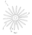
- FIG. 1 shows a lancet wheel 1, which by encapsulating the in FIG. 2 Lanzettenradrohlings 2 was produced with plastic.
- the lancet wheel 1 or the lancet wheel blank 2 have a plurality of annularly arranged lancets 3, which have a lancet body 3b terminating in a lancet tip 3a.
- the lancet tips 3a are in the in FIG. 1 illustrated lancet wheel 1 of a sterile protection 4, for example, foam, surrounded and therefore not visible.
- the lancet wheel 1 has a carrier 5 which is designed as a frame and carries the lancets 3.
- the lancets 3 are connected via webs 6 to the carrier 5, which allow an erection of the lancets 3 in a position of use.
- a lancet 3 is shown in its erected position of use.
- the webs 6 have a plastic body having a desired bending point around which the webs are bent to erect the lancets.
- the desired bending point is predetermined by a notch in the plastic body.
- the plastic body of the webs 6 pass into the plastic body of the carrier 5.
- the plastic body of the webs 6 and the plastic body of the carrier 5 are generated during encapsulation of the lancet blank 2 as a one-piece injection-molded part.
- plastic bodies of the webs 6 are outgoing of the lancet bodies 3b metal webs 7 of in FIG. 2 embedded Lanzettenradrohlings 2 embedded.
- metal webs 7 of in FIG. 2 embedded Lanzettenradrohlings 2 embedded.
- the metal web 7 preferably at least twice as wide, in particular at least three times as wide, in the illustrated embodiment more than five times as wide. In this way, the effort required to erect the lancets 3 and thus to bend the webs 6 by the metal web 7 is only slightly increased.
- the radially outwardly directed lancet tips 3a are enclosed by a ring 5a of the carrier 5 and thus protected against unintentional contact during the handling of the lancet wheel 1.
- the carrier 5 also has a stop 5b in the form of an annular disc, which permits an erection of the lancets 3 only in one direction, namely away from the annular disc 5b. In this way, the risk of damage to the lancet wheel 2 or injury during handling by accidental bending of a web 6 is reduced.
- a further part of the carrier 5 is formed by a metal disc 5c of the lancet wheel blank 2, from which the metal webs 7 go out.
- the metal disc 5c in the illustrated embodiment, an annular disc is embedded in the plastic body of the carrier 5 by encapsulation.
- the formed of plastic carrier body 5 of the lancet wheel 1 forms in the illustrated embodiment, a lancet magazine, which facilitates the handling of the lancet and a coupling element for coupling to a shunting device of a lancing device forms, with the lancets 3 of the lancet wheel 1 are moved sequentially in their use position
- the coupling element may for example be formed as a hole 8 for attachment to a shaft of a puncturing device.
- the hole 8 may be arranged as a blind hole or as a through hole in the carrier 5.
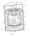
- FIG. 3 shows an embodiment of a puncturing device 10, which forms a lancing system together with a lancet wheel 1.
- the puncturing device 10 has a housing 11 with a removable housing for exchanging a lancet wheel housing cover 12th
- a housing opening 13 is arranged, to which a body part can be applied for generating a puncture wound.
- the lancet wheel 1 is inserted in the puncturing device 10 onto a shaft 14 with which the lancets 3 can be successively positioned for use by rotating the lancet wheel 1.
- the lancets 3 are erected with a pivoting device 15 in the use position, which is formed in the illustrated embodiment as a movable in the stinging direction slider. If the slider 15 is moved in the stinging direction, it encounters a lancet 3 positioned under the opening 13 so that it is erected into the use position in which its lancet tip 3a points towards the housing opening 13.
- the web 6 kinks at the defined by the notch target bending point.
- the lancing drive 16 of the illustrated lancing device 10 moves the entire lancet wheel 1 in the stiching direction.
- the force for this is applied by a drive spring 17, for example a spiral spring, which acts on a link control via a rotor.
- the drive spring is tensioned by means of a clamping disc, by this is rotated by 180 °.
- the lancet wheel is automatically indexed by a gear around a lancet 3, ie in the illustrated embodiment, by 18 °, since the lancet wheel 1 has twenty lancets 3.
- the sterile protection 4 can remain on the lancet 3 during a puncture movement or be removed beforehand.
- the sterile protection 4 is formed as a foam, it is pushed together upon impact of the lancet 3 on an applied to the housing opening 13 body part and therefore hinders the lancet movement at most insignificant.
- the lancet wheel 1 can be provided with a removable handle 20, as shown in Figure 11.
- a worn lancet wheel 1 can after removing the housing cap 12 are ejected from the puncturing device 10 by means of an ejector by pressing a button.
Abstract
Description
Die Erfindung geht aus von einem Lanzettenrad mit den im Oberbegriff des Anspruchs 1 angegebenen Merkmalen, wie es aus der
Die Lanzetten des aus der
Dies ist ein wichtiger Vorteil gegenüber aus der
Das aus der
Nachteilig an einem Stechsystem mit den aus der
Aufgabe der Erfindung ist es, einen Weg aufzuzeigen, wie ein Stechsystem mit Lanzettenrädern gemäß dem Oberbegriff des Anspruchs 1 kostengünstiger verwirklicht werden kann.The object of the invention is to show a way how a lancing system with lancet wheels according to the preamble of
Diese Aufgabe wird erfindungsgemäß durch ein Lanzettenrad mit den im Anspruch 1 angegebenen Merkmalen gelöst. Vorteilhafte Weiterbildungen der Erfindung sind Gegenstand der Unteransprüche. Die Aufgabe wird auch durch ein Verfahren zur Herstellung eines solchen Lanzettenrads mit den im Anspruch 11 angegebenen Merkmalen gelöst.This object is achieved by a lancet wheel with the features specified in
Wegen der radialen Ausrichtung der Lanzetten mit radial verlaufenden Stegen kann ein erfindungsgemäßes Lanzettenrad eine vorteilhaft große Anzahl von Lanzetten aufweisen, was dazu beiträgt, die Kosten des Stechsystems zu senken, da die Kosten pro Lanzette reduziert werden können. Zudem wird für jede Lanzette nur ein einziger Steg benötigt, was wegen einer einfacheren Geometrie die Herstellung des Lanzettenrads vereinfacht und ebenfalls Kosteneinsparungen ermöglicht.Because of the radial alignment of the lancets with radially extending ridges, a lancet wheel according to the invention can have an advantageously large number of lancets, which helps to reduce the costs of the lancing system, since the costs per lancet can be reduced. In addition, for each lancet only a single bridge is needed, which simplifies the production of the lancet wheel because of a simpler geometry and also allows cost savings.
Obwohl ein erfindungsgemäßes Lanzettenrad wesentlich mehr Lanzetten aufweisen kann, als es bei einem aus der
Die Soll-Biegestelle kann besonders vorteilhaft ausgebildet werden, indem die Stege eines erfindungsgemäßen Lanzettenrads mit einem Kunststoffkörper versehen werden, der ein Gelenk aufweist und auf diese Weise die Soll-Biegestelle vorgibt. Beispielsweise kann der Kunststoffkörper als Soll-Biegestelle eine Schwächung, beispielsweise in Form einer Kerbe oder Perforation, aufweisen, um welche die Stege zum Aufrichten der Lanzetten gebogen werden.The desired bending point can be formed particularly advantageous by the webs of a lancet wheel according to the invention are provided with a plastic body having a joint and in this way predetermines the desired bending point. For example, the plastic body as a target bending point a weakening, for example in the form of a notch or perforation, have around which the webs are bent to erect the lancets.
Bevorzugt sind die Stege eines erfindungsgemäßen Lanzettenrades federnd um die Soll-Biegestelle biegsam, so dass eine aufgerichtete Lanzetten aus der Gebrauchsposition nach einem Stich ohne äußere Krafteinwirkung wieder in eine ebene Lage übergeht. Bei dieser ebenen Lage handelt es sich bevorzugt um die Ausgangsposition der Lanzette. Möglich ist es aber auch, dass eine Lanzette aus der Gebrauchsposition in eine ebene Lage schnappt, in der sie umgekehrt wie in der Ausgangsposition orientiert ist. Wegen der federnden Beweglichkeit der Stege kann eine Lanzette in einem Stechgerät mit einer Schwenkeinrichtung, beispielsweise einem die Lanzette aus der Radebene drückenden Stift, in die Gebrauchposition gebracht werden und kehrt von selbst in eine ebene Position zurück, sobald die Schwenkeinrichtung nicht mehr auf sie einwirkt. Der erfindungsgemäße Kunststoffkörper der Stege ermöglicht vorteilhaft elastische Eigenschaften, die zum Aufrichten der Lanzetten eine Biegung um einen rechten Winkel ermöglichen und nach einem Stich ohne äußere Krafteinwirkung für eine Bewegung der Lanzetten in eine ebene Lage sorgen.Preferably, the webs of a lancet wheel according to the invention are resilient about the desired bending point, so that an erect lancet from the use position after a stitch passes without external force again in a flat position. This level position is preferably the starting position of the lancet. But it is also possible that a lancet from the use position snaps into a flat position in which it is oriented inversely as in the starting position. Because of the resilient mobility of the webs, a lancet in a lancing device with a pivoting device, such as a pin pushing the lancet out of the wheel plane pin, be placed in the use position and returns by itself in a flat position as soon as the pivoting device no longer acts on them. The plastic body of the webs according to the invention advantageously allows elastic properties that allow for erecting the lancets a bend at a right angle and provide for a stitch without external force for movement of the lancets in a flat position.
Ein erfindungsgemäßes Lanzettenrad kann kostengünstig hergestellt werden, indem ein Lanzettenradrohling, der ringförmig angeordnete Lanzetten mit einem in einer Spitze endenden Lanzettenkörper aufweist, aus Blech ausgeschnitten und anschließend mit Kunststoff umspritzt wird. Das Ausschneiden des Lanzettenradrohlings kann beispielsweise durch Laserschneiden oder Stanzen, besonders vorteilhaft durch Ätzen, erfolgen.A lancet wheel according to the invention can be produced inexpensively by cutting out a lancet wheel blank having ring-shaped lancets with a lancet body terminating in a tip, which is cut from sheet metal and then encapsulated with plastic. The cutting out of the lancet wheel blank can be effected, for example, by laser cutting or punching, particularly advantageously by etching.
Durch das Umspritzen mit Kunststoff können kostengünstig Kunststoffkörper der die Lanzetten mit einem Träger verbindenden Stege ausgebildet und Soll-Biegestellen zum Aufrichten der Lanzetten vorgegeben werden. Dabei kann auch ein Kunststoffkörper eines mit den Stegen verbundenen Trägers ausgebildet werden. Der Kunststoffkörper des Trägers kann in die Kunststoffkörper der Lanzetten übergehen, so dass die Kunststoffkörper der Stege und der Kunststoffkörper des Trägers integral oder einstückig ausgebildet sind.By encapsulating with plastic plastic body of the lancets can be inexpensively formed with a carrier connecting webs and setpoint bending points for erecting the lancets can be specified. In this case, a plastic body of a carrier connected to the webs can be formed. The plastic body of the carrier can pass into the plastic body of the lancet, so that the plastic body of the webs and the plastic body of the carrier are integrally or integrally formed.
Ein erfindungsgemäßes Herstellungsverfahren kommt mit vorteilhaft wenigen Handhabungs- und Arbeitsschritten aus. Ein einstückiger Lanzettenradrohling lässt sich leicht aus Blech ausschneiden und anschließend in ein Spritzgusswerkzeug einlegen. Für ein erfindungsgemäßes Lanzettenrad genügen an sich bereits zwei Teile, nämlich der Lanzettenradrohling und ein um den Lanzettenradrohling gespritzter Kunststoffkörper. Zusätzlich können die Lanzettenspitzen mit vorteilhaft geringem Aufwand mit einem Sterilschutz versehen werden, beispielsweise indem die Lanzettenspitzen mit Schaumstoff umspritzt werden.An inventive manufacturing process comes with advantageous few handling and operations. A one-piece lancet wheel blank can be easily cut out of sheet metal and then inserted into an injection mold. For a lancet wheel according to the invention, two parts, namely the lancet wheel blank and a plastic body injected around the lancet wheel blank, are already sufficient. In addition, the lancet tips can be provided with advantageously little effort with a sterile protection, for example by the lancet tips are encapsulated with foam.
Die Metallstege des Lanzettenradrohlings können nach dem Einlegen in ein Spritzgusswerkzeug durchtrennt und/oder entfernt werden, so dass beim Aufrichten der Lanzetten kein Metallteil gebogen werden muss. Der mit dem Durchtrennen der Metallstege verbundene Arbeitsschritt lässt sich aber auch einzusparen, indem die von den Lanzettenkörpern ausgehenden Metallstege in den Kunststoffkörpern der Stege eingebettet werden und sich durch die Soll-Biegestelle hindurch erstrecken. Bevorzugt ist der Kunststoffkörper an der Soll-Biegestelle breiter als der Metallsteg, besonders bevorzugt mindestens doppelt so breit, insbesondere mindestens dreimal so breit. Auf diese Weise wird der zum Aufrichten einer Lanzette erforderliche Kraftaufwand durch den Metallsteg nur unwesentlich erhöht.The metal webs of the lancet wheel blank can be severed and / or removed after insertion into an injection mold, so that no metal part has to be bent when erecting the lancets. However, the step connected with the severing of the metal webs can also be saved by embedding the metal webs emanating from the lancet bodies in the plastic bodies of the webs and extending through the desired bending point. Preferably, the plastic body is wider at the desired bending point than the metal web, more preferably at least twice as wide, in particular at least three times as wide. In this way, the force required to erect a lancet force is increased only slightly by the metal web.
Eine vorteilhafte Weiterbildung der Erfindung sieht vor, dass der Träger einen Ring aufweist, der die Lanzetten umschließt. Auf diese Weise lassen sich die Lanzetten vor unbeabsichtigtem Kontakt bei der Handhabung des Lanzettenrades schützen. Zudem kann ein Lanzettenrad an einem solchen Ring gut gegriffen werden. Der Ring kann beim Umspritzen des Lanzettenradrohlings mit Kunststoff ohne zusätzlichen Aufwand ausgebildet werden.An advantageous development of the invention provides that the carrier has a ring which encloses the lancets. In this way, the lancets can be protected against unintentional contact during handling of the lancet wheel. In addition, a lancet wheel can be easily grasped on such a ring. The ring can be formed with plastic without encumbering the lancet wheel blank.
Bevorzugt bildet der Träger auf einer Seite des Lanzettenrades einen Anschlag, der ein Aufrichten der Lanzetten nur in einer Richtung zulässt. Der Anschlag kann beispielsweise als eine Ringscheibe ausgebildet sein. Ein solcher Anschlag reduziert als Knickschutz die Gefahr eine Beschädigung des Lanzettenrades oder einer Verletzung bei der Handhabung durch ein versehentliches Biegen eines Steges, da die Lanzetten wegen des Anschlags nur in einer Richtung, nämlich weg von dem Anschlag, aufgerichtet werden können. In ihrer Ausgangsstellung vor dem Aufrichten in die Gebrauchsstellung können die Lanzetten auf dem Anschlag aufliegen oder in einem Abstand davon angeordnet sein.Preferably, the carrier forms a stop on one side of the lancet wheel, which allows the lancets to be erected only in one direction. The stop may be formed, for example, as an annular disc. Such a stop reduces the risk of damage to the lancet wheel or injury during handling by accidentally bending a web as kink protection, since the lancets can only be erected in one direction, namely away from the stop, because of the stop. In its initial position before raising into the position of use, the lancets may rest on the stop or be arranged at a distance therefrom.
Eine weitere vorteilhafte Weiterbildung der Erfindung sieht vor, dass das Lanzettenrad in seinem Zentrum ein Loch aufweist, mit dem es beispielsweise auf eine Welle eines Stechgeräts aufgesteckt werden kann.A further advantageous development of the invention provides that the lancet wheel has a hole in its center, with which it can be plugged, for example, onto a shaft of a puncturing device.
Eine weitere vorteilhafte Weiterbildung der Erfindung sieht vor, dass die Lanzettenspitzen von einem Sterilschutz umgeben sind. Der Sterilschutz kann beispielsweise um die Lanzettenspitzen herumgespritzt werden, beispielsweise als Schaumstoff. Ein derartiger Sterilschutz wird bei einem Lanzettenstich von selbst von der Lanzettenspitze abgestreift. Ein Sterilschutz lässt sich auch durch Folie ausbilden, beispielsweise indem der Lanzettenradrohling zumindest im Bereich der Lanzettenspitzen beidseitig mit Folie bedeckt wird. Durch anschließendes Umspritzen des Lanzettenradrohlings mit Kunststoff lässt sich die Sterilschutzfolie ohne zusätzlichen Aufwand befestigen. Beim Aufrichten einer Lanzette wird die Sterilschutzfolie im Bereich der betreffenden Lanzette durchbrochen.A further advantageous embodiment of the invention provides that the lancet tips are surrounded by a sterile protection. The sterile protection can, for example, be sprayed around the lancet tips, for example as a foam. Such a sterile protection is automatically stripped off the lancet tip during a lancet puncture. A sterile protection can also be formed by film, for example by covering the lancet wheel blank with foil on both sides, at least in the area of the lancet tips. By subsequent encapsulation of the lancet wheel blank with plastic, the sterile protective film can be attached without additional effort. When setting up a lancet, the sterile protective foil in the area of the relevant lancet is broken.
Eine weitere vorteilhafte Weiterbildung der Erfindung sieht vor, dass das Lanzettenrad einen Griff aufweist, der sich senkrecht zu einer Radebene, in der die Lanzetten liegen, erstreckt. Ein solcher Griff erleichtert das Einlegen des Lanzettenrades in ein Stechgerät. Der Griff kann über eine Sollbruchstelle mit dem Lanzettenrad verbunden sein. Möglich ist es auch, den Griff separat auszubilden und bei Bedarf mit dem eigentlichen Lanzettenrad zu verbinden, beispielsweise, indem der Griff in ein zentrisches Loch gesteckt wird.A further advantageous development of the invention provides that the lancet wheel has a handle which extends perpendicular to a wheel plane in which the lancets lie. Such a handle facilitates the insertion of the lancet wheel in a puncturing device. The handle can be connected via a predetermined breaking point with the lancet wheel. It is also possible to form the handle separately and if necessary with the to connect the actual lancet wheel, for example, by the handle is inserted into a centric hole.
Ein zur Herstellung eines erfindungsgemäßen Lanzettenrades aus Metall ausgeschnittener Lanzettenradrohling mit mehreren ringförmig angeordneten Lanzetten, die radial ausgerichtet sind und einen in einer Lanzettenspitze endenden Lanzettenkörper aufweisen, und einem Träger, mit dem die Lanzetten über radial verlaufende Stege verbunden sind, die ein Aufrichten der Lanzetten in eine Gebrauchsstellung ermöglichen, kann prinzipiell auch ohne Umspritzen mit Kunststoff als Lanzettenrad verwendet werden. Soll-Biegestellen können an den Stegen in einem solchen Fall beispielsweise durch Einprägungen oder eine andere Schwächung des Steges vorgegeben werden.A lancet wheel blank cut out of metal for producing a lancet wheel according to the invention having a plurality of annularly arranged lancets which are radially aligned and have a lancet body terminating in a lancet tip, and a support to which the lancets are connected via radially extending webs which cause the lancets to be erected enable a position of use, can be used in principle without overmolding with plastic as a lancet wheel. Target bending points can be specified on the webs in such a case, for example, by imprints or other weakening of the web.
Bevorzugt sind die Lanzettenspitzen bei einem erfindungsgemäßen Lanzettenrad radial nach außen gerichtet. Auf diese Weise können die Stege Strahlenförmig von einem gemeinsamen Zentrum ausgehen, was eine vorteilhaft einfache Fertigung ermöglicht.Preferably, the lancet tips are directed radially outward in a lancet wheel according to the invention. In this way, the webs can radiate from a common center, which allows an advantageously simple production.
Bei einem erfindungsgemäßen Lanzettenrad kann der Kunststoffkörper als Trägerkörper der Lanzetten vorteilhaft ein Lanzettenmagazin bilden, das eine einfache Handhabung ermöglicht und ein Kopplungselement zur Ankopplung an eine Fortschalteinrichtung eines Stechgeräts ausbildet. Bevorzugt wird deshalb beim Umspritzen eines metallenen Lanzettenradrohlings mit Kunststoff ein Trägerkörper erzeugt, der ein Kopplungselement zur Ankopplung an eine Fortschalteinrichtung eines Stechgeräts ausbildet, mit der die Lanzetten des Lanzettenrades nacheinander in ihre Gebrauchsposition bewegt werden können. Im einfachsten Fall kann das Kopplungselement beispielsweise eine Öffnung sein, in die eine Welle einer Fortschalteinrichtung gesteckt werden kann. Ein von dem Kunststoffkörper gebildetes Lanzettenmagazin kann vorteilhaft zudem einen Schutz der Lanzetten bewirken, beispielsweise indem der Trägerkörper einen Ring aufweist, der die Lanzetten umgibt.In a lancet wheel according to the invention, the plastic body can advantageously form a lancet magazine as the carrier body of the lancets, which enables easy handling and forms a coupling element for coupling to a indexing device of a puncturing device. Preferably, therefore, during encapsulation of a metal lancet wheel blank with plastic, a carrier body is produced which forms a coupling element for coupling to a indexing device of a puncturing device with which the lancets of the lancet wheel can be successively moved into their position of use. In the simplest case, the coupling element may for example be an opening into which a shaft of a shunting device can be inserted. A lancet magazine formed by the plastic body can advantageously also bring about protection of the lancets, for example by the carrier body having a ring surrounding the lancets.
Weitere Einzelheiten und Vorteile der Erfindung werden an Ausführungsbeispielen unter Bezugnahme auf die beigefügten Zeichnungen erläutert. Gleiche und einander entsprechende Teile sind dabei mit übereinstimmenden Bezugszahlen gekennzeichnet. Es zeigen:
- Figur 1:
- ein Ausführungsbeispiel eines erfindungsgemäßen Lanzettenrads;
- Figur 2:
- die Metallteile des in
Figur 1 - Figur 3:
- ein Ausführungsbeispiel eines Stechsystems mit dem dargestellten Lanzettenrad; und
- Figur 4:
- das in
Figur 1
- FIG. 1:
- an embodiment of a lancet wheel according to the invention;
- FIG. 2:
- the metal parts of the in
FIG. 1 illustrated lancet wheel; - FIG. 3:
- an embodiment of a lancing system with the illustrated lancet wheel; and
- FIG. 4:
- this in
FIG. 1 illustrated lancet wheel with a handle for insertion into a lancing device.
Das Lanzettenrad 1 hat einen als Rahmen ausgebildeten Träger 5, der die Lanzetten 3 trägt. Die Lanzetten 3 sind über Stege 6 mit dem Träger 5 verbunden, die ein Aufrichten der Lanzetten 3 in eine Gebrauchsstellung ermöglichen. In
Die Stege 6 haben einen Kunststoffkörper, der eine Soll-Biegestelle aufweist, um welche die Stege zum Aufrichten der Lanzetten gebogen werden. Bei dem dargestellten Ausführungsbeispiel ist die Soll-Biegestelle durch eine Kerbe in dem Kunststoffkörper vorgegeben. Die Kunststoffkörper der Stege 6 gehen in den Kunststoffkörper des Trägers 5 über. Die Kunststoffkörper der Stege 6 und der Kunststoffkörper des Trägers 5 werden beim Umspritzen des Lanzettenrohlings 2 als einstückiges Spritzgussteil erzeugt.The
In den Kunststoffkörpern der Stege 6 sind von den Lanzettenkörpern 3b ausgehende Metallstege 7 des in
Die radial nach außen gerichteten Lanzettenspitzen 3a sind von einem Ring 5a des Trägers 5 umschlossen und auf diese Weise vor unbeabsichtigtem Kontakt bei der Handhabung des Lanzettenrades 1 geschützt. Der Träger 5 weist zudem einen Anschlag 5b in Form einer Ringscheibe auf, der ein Aufrichten der Lanzetten 3 nur in einer Richtung, nämlich weg von der Ringscheibe 5b, zulässt. Auf diese Weise ist die Gefahr eine Beschädigung des Lanzettenrades 2 oder einer Verletzung bei der Handhabung durch ein versehentliches Biegen eines Steges 6 reduziert.The radially outwardly directed lancet tips 3a are enclosed by a
Bei dem dargestellten Ausführungsbeispiel ist ein weiterer Teil des Trägers 5 durch eine Metallscheibe 5c des Lanzettenradrohlings 2 gebildet, von der die Metallstege 7 ausgehen. Die Metallscheibe 5c, bei dem dargestellten Ausführungsbeispiel eine Ringscheibe, ist in den Kunststoffkörper des Trägers 5 durch Umspritzen eingebettet.In the illustrated embodiment, a further part of the
Der aus Kunststoff gebildete Trägerkörper 5 des Lanzettenrades 1 bildet bei dem dargestellten Ausführungsbeispiel ein Lanzettenmagazin aus, das die Handhabung der Lanzetten erleichtert und ein Kopplungselement zum Ankoppeln an eine Fortschalteinrichtung eines Stechgeräts ausbildet, mit der die Lanzetten 3 des Lanzettenrades 1 nacheinander in ihre Gebrauchsposition bewegt werden können. Das Kopplungselement kann beispielsweise als ein Loch 8 zum Aufstecken auf eine Welle eines Stechgeräts ausgebildet sein. Das Loch 8 kann als Sackloch oder als durchgehendes Loch in dem Träger 5 angeordnet sein.The formed of
In der Gehäusekappe 12 ist eine Gehäuseöffnung 13 angeordnet, an die ein Körperteil zum Erzeugen einer Stichwunde angelegt werden kann.In the
Das Lanzettenrad 1 ist in dem Stechgerät 10 auf eine Welle 14 gesteckt, mit der die Lanzetten 3 durch Drehen des Lanzettenrads 1 nacheinander zum Gebrauch positioniert werden können. Die Lanzetten 3 werden mit einer Schwenkeinrichtung 15 in die Gebrauchsposition aufgerichtet, die bei dem dargestellten Ausführungsbeispiel als ein in Stichrichtung beweglicher Schieber ausgebildet ist. Wird der Schieber 15 in Stichrichtung verschoben, so trifft er auf eine unter der Öffnung 13 positionierte Lanzette 3, so dass diese in die Gebrauchsposition aufgerichtet wird, in der ihre Lanzettenspitze 3a zu der Gehäuseöffnung 13 deutet. Beim Aufrichten der Lanzette 3 knickt der Steg 6 an der durch die Kerbe definierten Soll-Biegestelle.The
Bei einem Stich bewegt der Stechantrieb 16 des dargestellten Stechgeräts 10 das gesamte Lanzettenrad 1 in Stichrichtung. Die Kraft hierfür wird von einer Antriebsfeder 17, beispielsweise eine Spiralfeder, aufgebracht, die über einen Rotor auf eine Kulissensteuerung einwirkt. Die Antriebsfeder wird mittels einer Spannscheibe gespannt, indem diese um 180° gedreht wird. Dabei wird das Lanzettenrad über ein Getriebe automatisch um eine Lanzette 3 weitergetaktet, bei dem dargestellten Ausführungsbeispiel also um 18°, da das Lanzettenrad 1 zwanzig Lanzetten 3 hat.In one pass, the lancing
Der Sterilschutz 4 kann während einer Stichbewegung an der Lanzette 3 bleiben oder vorher entfernt werden. Indem der Sterilschutz 4 als Schaumstoff ausgebildet ist, wird er beim Auftreffen der Lanzette 3 auf ein an die Gehäuseöffnung 13 angelegtes Körperteil zusammen geschoben und behindert deshalb die Lanzettenbewegung allenfalls unwesentlich.The
Sobald eine Lanzette 3 nicht mehr von dem Schieber 15 in ihrer aufgerichteten Stellung gehalten wird, schnappt sie wieder in eine ebene Lage zurück.Once a
Um das Einlegen des Lanzettenrads 1 in das Stechgerät 10 zu erleichtern, kann das Lanzettenrad 1 mit einem abnehmbaren Griff 20 versehen werden, wie er in Figur 11 gezeigt ist. Ein verbrauchtes Lanzettenrad 1 kann nach dem Abnehmen der Gehäusekappe 12 mittels eines Auswerfers per Knopfdruck aus dem Stechgerät 10 ausgeworfen werden.In order to facilitate the insertion of the
- 11
- Lanzettenradlancet
- 22
- LanzettenradrohlingLanzettenradrohling
- 33
- Lanzettenlancets
- 3a3a
- LanzettenspitzeLancet tip
- 3b3b
- LanzettenkörperLancet body
- 44
- Sterilschutzsterile protection
- 55
- Trägercarrier
- 5a5a
- Ringring
- 5b5b
- Anschlagattack
- 5c5c
- Metallscheibemetal disc
- 66
- Stegweb
- 77
- Metallstegmetal bar
- 88th
- Lochhole
- 1010
- Stechgerätlancing device
- 1111
- Gehäusecasing
- 1212
- Gehäusekappehousing cap
- 1313
- Gehäuseöffnunghousing opening
- 1414
- Wellewave
- 1515
- SchwenkeinrichtungPivot means
- 1616
- Stechantrieblancing drive
- 1717
- Antriebsfederdriving spring
- 2020
- GriffHandle
Claims (15)
mehreren ringförmig angeordneten Lanzetten (3), die einen in einer Lanzettenspitze (3a) endenden Lanzettenkörper (3b) aufweisen, und
einem Träger (5), mit dem die Lanzetten (3) über radial verlaufende Stege (6) verbunden sind, die ein Aufrichten der Lanzetten (3) in eine Gebrauchsstellung ermöglichen,
dadurch gekennzeichnet, dass die Lanzetten (3) radial ausgerichtet sind und dass die Stege (6) einen Kunststoffkörper haben, der eine Soll-Biegestelle vorgibt, um welche die Stege (6) zum Aufrichten der Lanzetten (3) gebogen werden.Lancet wheel with
a plurality of annularly arranged lancets (3) which have a lancet body (3b) terminating in a lancet tip (3a), and
a carrier (5) to which the lancets (3) are connected by means of radially extending webs (6) which allow the lancets (3) to be set up in a position of use,
characterized in that the lancets (3) are radially aligned and that the webs (6) have a plastic body which defines a desired bending point, around which the webs (6) for erecting the lancets (3) are bent.
Priority Applications (6)
| Application Number | Priority Date | Filing Date | Title |
|---|---|---|---|
| EP08008393A EP2113197A1 (en) | 2008-05-03 | 2008-05-03 | Lancet wheel and method for manufacturing a lancet wheel |
| CN200980115832.5A CN102014751B (en) | 2008-05-03 | 2009-04-28 | Lancet wheel and method for producing a lancet wheel |
| EP09741827.1A EP2271262B1 (en) | 2008-05-03 | 2009-04-28 | Lancet wheel and method for manufacturing a lancet wheel |
| PCT/EP2009/003057 WO2009135608A1 (en) | 2008-05-03 | 2009-04-28 | Lancet wheel and method for producing a lancet wheel |
| US12/891,844 US9066689B2 (en) | 2008-05-03 | 2010-09-28 | Lancet wheel and method for producing a lancet wheel |
| HK11110598.2A HK1155931A1 (en) | 2008-05-03 | 2011-10-06 | Lancet wheel and method for producing a lancet wheel |
Applications Claiming Priority (1)
| Application Number | Priority Date | Filing Date | Title |
|---|---|---|---|
| EP08008393A EP2113197A1 (en) | 2008-05-03 | 2008-05-03 | Lancet wheel and method for manufacturing a lancet wheel |
Publications (1)
| Publication Number | Publication Date |
|---|---|
| EP2113197A1 true EP2113197A1 (en) | 2009-11-04 |
Family
ID=39817106
Family Applications (2)
| Application Number | Title | Priority Date | Filing Date |
|---|---|---|---|
| EP08008393A Withdrawn EP2113197A1 (en) | 2008-05-03 | 2008-05-03 | Lancet wheel and method for manufacturing a lancet wheel |
| EP09741827.1A Not-in-force EP2271262B1 (en) | 2008-05-03 | 2009-04-28 | Lancet wheel and method for manufacturing a lancet wheel |
Family Applications After (1)
| Application Number | Title | Priority Date | Filing Date |
|---|---|---|---|
| EP09741827.1A Not-in-force EP2271262B1 (en) | 2008-05-03 | 2009-04-28 | Lancet wheel and method for manufacturing a lancet wheel |
Country Status (5)
| Country | Link |
|---|---|
| US (1) | US9066689B2 (en) |
| EP (2) | EP2113197A1 (en) |
| CN (1) | CN102014751B (en) |
| HK (1) | HK1155931A1 (en) |
| WO (1) | WO2009135608A1 (en) |
Cited By (5)
| Publication number | Priority date | Publication date | Assignee | Title |
|---|---|---|---|---|
| EP2311374A1 (en) * | 2009-10-13 | 2011-04-20 | Roche Diagnostics GmbH | Apparatus for retrieving and analysing blood; coupling mechanism for lancets |
| WO2012089521A1 (en) * | 2010-12-30 | 2012-07-05 | Roche Diagnostics Gmbh | Handheld medical diagnostic devices |
| US8852123B2 (en) | 2010-12-30 | 2014-10-07 | Roche Diagnostics Operations, Inc. | Handheld medical diagnostic devices housing with sample transfer |
| US9486164B2 (en) | 2010-12-30 | 2016-11-08 | Roche Diabetes Care, Inc. | Handheld medical diagnostic device with lancet and sample transfer |
| US9717452B2 (en) | 2010-12-30 | 2017-08-01 | Roche Diabetes Care, Inc. | Handheld medical diagnostic devices with lancing speed control |
Families Citing this family (2)
| Publication number | Priority date | Publication date | Assignee | Title |
|---|---|---|---|---|
| DK2802267T3 (en) * | 2012-01-10 | 2016-02-22 | Sanofi Aventis Deutschland | Cartridge |
| JP6058785B2 (en) * | 2012-04-16 | 2017-01-11 | エフ ホフマン−ラ ロッシュ アクチェン ゲゼルシャフト | Method and structure for assembling a lancet housing assembly of a portable medical diagnostic device |
Citations (6)
| Publication number | Priority date | Publication date | Assignee | Title |
|---|---|---|---|---|
| EP0985376A1 (en) * | 1998-09-07 | 2000-03-15 | Roche Diagnostics GmbH | Lancet dispenser |
| EP1360934A1 (en) | 2002-05-09 | 2003-11-12 | Lifescan, Inc. | Devices and methods for accessing and analyzing physiological fluid |
| EP1369934A1 (en) | 2002-05-22 | 2003-12-10 | Unity Opto Technology Co., Ltd. | Light emitting diode lamp with light emitting diode module having improved heat dissipation |
| WO2005118690A1 (en) | 2004-06-01 | 2005-12-15 | Rosti A/S | A method for hardening at a surface a component, devices having one or more hardened surfaces and devices for retaining and presenting for use a plurality of components |
| WO2007060004A1 (en) * | 2005-11-25 | 2007-05-31 | Roche Diagnostics Gmbh | Kinked lancet |
| EP1880671A1 (en) * | 2006-07-18 | 2008-01-23 | Roche Diagnostics GmbH | Lancet wheel |
Family Cites Families (49)
| Publication number | Priority date | Publication date | Assignee | Title |
|---|---|---|---|---|
| FR2583174B1 (en) * | 1985-06-07 | 1987-07-31 | Cgr Ultrasonic | ECHOGRAPHY PROBE |
| IL80628A0 (en) * | 1985-11-18 | 1987-02-27 | Bajada Serge | Apparatus for testing the sensory system in humans or animals |
| US4794926A (en) * | 1986-11-24 | 1989-01-03 | Invictus, Inc. | Lancet cartridge |
| IL101720A (en) * | 1992-04-29 | 1998-09-24 | Mali Tech Ltd | Needle for syringe or the like |
| US5395388A (en) * | 1993-11-15 | 1995-03-07 | Schraga; Steven | Single unit lancet device |
| US5647851A (en) * | 1995-06-12 | 1997-07-15 | Pokras; Norman M. | Method and apparatus for vibrating an injection device |
| US5613978A (en) | 1996-06-04 | 1997-03-25 | Palco Laboratories | Adjustable tip for lancet device |
| US5829589A (en) * | 1997-09-12 | 1998-11-03 | Becton Dickinson And Company | Pen needle magazine dispenser |
| US6210420B1 (en) * | 1999-01-19 | 2001-04-03 | Agilent Technologies, Inc. | Apparatus and method for efficient blood sampling with lancet |
| US6045567A (en) * | 1999-02-23 | 2000-04-04 | Lifescan Inc. | Lancing device causing reduced pain |
| US6660018B2 (en) * | 1999-03-08 | 2003-12-09 | Agilent Technologies, Inc. | Multiple lancet device |
| US6306152B1 (en) * | 1999-03-08 | 2001-10-23 | Agilent Technologies, Inc. | Lancet device with skin movement control and ballistic preload |
| US6231531B1 (en) * | 1999-04-09 | 2001-05-15 | Agilent Technologies, Inc. | Apparatus and method for minimizing pain perception |
| US6558402B1 (en) | 1999-08-03 | 2003-05-06 | Becton, Dickinson And Company | Lancer |
| US6228100B1 (en) * | 1999-10-25 | 2001-05-08 | Steven Schraga | Multi-use lancet device |
| GB0003991D0 (en) | 2000-02-22 | 2000-04-12 | Owen Mumford Ltd | Improvements relating to skin prickers |
| US6706159B2 (en) * | 2000-03-02 | 2004-03-16 | Diabetes Diagnostics | Combined lancet and electrochemical analyte-testing apparatus |
| DE10047419A1 (en) * | 2000-09-26 | 2002-04-11 | Roche Diagnostics Gmbh | Lancet system |
| EP1203563A3 (en) | 2000-10-31 | 2004-01-02 | Boehringer Mannheim Gmbh | Analyzing mean with integrated lancet |
| DE10057832C1 (en) * | 2000-11-21 | 2002-02-21 | Hartmann Paul Ag | Blood analysis device has syringe mounted in casing, annular mounting carrying needles mounted behind test strip and being swiveled so that needle can be pushed through strip and aperture in casing to take blood sample |
| CN100339044C (en) * | 2001-03-29 | 2007-09-26 | 因弗内斯医疗有限公司 | Integrated measuring apparatus for testing samples |
| DE60229988D1 (en) * | 2001-06-08 | 2009-01-02 | Roche Diagnostics Gmbh | Removal device for Körperflussigkeiten |
| US7025774B2 (en) * | 2001-06-12 | 2006-04-11 | Pelikan Technologies, Inc. | Tissue penetration device |
| US7004928B2 (en) * | 2002-02-08 | 2006-02-28 | Rosedale Medical, Inc. | Autonomous, ambulatory analyte monitor or drug delivery device |
| DE20213607U1 (en) | 2002-02-21 | 2003-07-03 | Hartmann Paul Ag | Blood analyzer for the determination of an analyte |
| US7226461B2 (en) * | 2002-04-19 | 2007-06-05 | Pelikan Technologies, Inc. | Method and apparatus for a multi-use body fluid sampling device with sterility barrier release |
| US7547287B2 (en) * | 2002-04-19 | 2009-06-16 | Pelikan Technologies, Inc. | Method and apparatus for penetrating tissue |
| US9314194B2 (en) * | 2002-04-19 | 2016-04-19 | Sanofi-Aventis Deutschland Gmbh | Tissue penetration device |
| US7491178B2 (en) * | 2002-04-19 | 2009-02-17 | Pelikan Technologies, Inc. | Method and apparatus for penetrating tissue |
| US20070142748A1 (en) * | 2002-04-19 | 2007-06-21 | Ajay Deshmukh | Tissue penetration device |
| US20030211619A1 (en) | 2002-05-09 | 2003-11-13 | Lorin Olson | Continuous strip of fluid sampling and testing devices and methods of making, packaging and using the same |
| US7192405B2 (en) | 2002-09-30 | 2007-03-20 | Becton, Dickinson And Company | Integrated lancet and bodily fluid sensor |
| EP1578286A4 (en) * | 2002-12-13 | 2009-01-14 | Pelikan Technologies Inc | Method and apparatus for measuring analytes |
| US8574895B2 (en) * | 2002-12-30 | 2013-11-05 | Sanofi-Aventis Deutschland Gmbh | Method and apparatus using optical techniques to measure analyte levels |
| US20040193202A1 (en) | 2003-03-28 | 2004-09-30 | Allen John J. | Integrated lance and strip for analyte measurement |
| WO2005006939A2 (en) | 2003-06-11 | 2005-01-27 | Pelikan Technologies, Inc. | Method and apparatus for body fluid sampling and analyte sensing |
| EP1653849B1 (en) | 2003-08-11 | 2010-10-06 | Pelikan Technologies Inc. | Method and apparatus for body fluid sampling with integrated analyte detecting member |
| US7223248B2 (en) | 2003-08-13 | 2007-05-29 | Lifescan, Inc. | Packaged medical device with a deployable dermal tissue penetration member |
| US8282576B2 (en) | 2003-09-29 | 2012-10-09 | Sanofi-Aventis Deutschland Gmbh | Method and apparatus for an improved sample capture device |
| WO2005065415A2 (en) | 2003-12-31 | 2005-07-21 | Pelikan Technologies, Inc. | Body fluid sampling device with conductive media |
| US7909776B2 (en) * | 2004-04-30 | 2011-03-22 | Roche Diagnostics Operations, Inc. | Lancets for bodily fluid sampling supplied on a tape |
| WO2005121759A2 (en) | 2004-05-24 | 2005-12-22 | Albatros Technologies Gmbh & Co. Kg | Device and method for analyte measurement |
| US8211038B2 (en) * | 2004-09-17 | 2012-07-03 | Abbott Diabetes Care Inc. | Multiple-biosensor article |
| WO2006038044A2 (en) | 2004-10-08 | 2006-04-13 | Owen Mumford Ltd | Skin lancing apparatus |
| EP1658897A1 (en) | 2004-11-22 | 2006-05-24 | Roche Diagnostics GmbH | Bent microfluidic device |
| EP1928304B1 (en) * | 2005-09-30 | 2012-10-24 | Intuity Medical, Inc. | Catalysts for body fluid sample extraction |
| US9186097B2 (en) * | 2007-09-17 | 2015-11-17 | Roche Diabetes Care, Inc. | Body fluid lancing, acquiring, and testing cartridge design |
| EP2042098A1 (en) * | 2007-09-26 | 2009-04-01 | Roche Diagnostics GmbH | Lancet cartridge |
| EP2050392B1 (en) * | 2007-10-15 | 2012-09-05 | Roche Diagnostics GmbH | Lancet wheel |
-
2008
- 2008-05-03 EP EP08008393A patent/EP2113197A1/en not_active Withdrawn
-
2009
- 2009-04-28 CN CN200980115832.5A patent/CN102014751B/en not_active Expired - Fee Related
- 2009-04-28 WO PCT/EP2009/003057 patent/WO2009135608A1/en active Application Filing
- 2009-04-28 EP EP09741827.1A patent/EP2271262B1/en not_active Not-in-force
-
2010
- 2010-09-28 US US12/891,844 patent/US9066689B2/en not_active Expired - Fee Related
-
2011
- 2011-10-06 HK HK11110598.2A patent/HK1155931A1/en not_active IP Right Cessation
Patent Citations (6)
| Publication number | Priority date | Publication date | Assignee | Title |
|---|---|---|---|---|
| EP0985376A1 (en) * | 1998-09-07 | 2000-03-15 | Roche Diagnostics GmbH | Lancet dispenser |
| EP1360934A1 (en) | 2002-05-09 | 2003-11-12 | Lifescan, Inc. | Devices and methods for accessing and analyzing physiological fluid |
| EP1369934A1 (en) | 2002-05-22 | 2003-12-10 | Unity Opto Technology Co., Ltd. | Light emitting diode lamp with light emitting diode module having improved heat dissipation |
| WO2005118690A1 (en) | 2004-06-01 | 2005-12-15 | Rosti A/S | A method for hardening at a surface a component, devices having one or more hardened surfaces and devices for retaining and presenting for use a plurality of components |
| WO2007060004A1 (en) * | 2005-11-25 | 2007-05-31 | Roche Diagnostics Gmbh | Kinked lancet |
| EP1880671A1 (en) * | 2006-07-18 | 2008-01-23 | Roche Diagnostics GmbH | Lancet wheel |
Cited By (7)
| Publication number | Priority date | Publication date | Assignee | Title |
|---|---|---|---|---|
| EP2311374A1 (en) * | 2009-10-13 | 2011-04-20 | Roche Diagnostics GmbH | Apparatus for retrieving and analysing blood; coupling mechanism for lancets |
| WO2011044971A3 (en) * | 2009-10-13 | 2012-04-26 | Roche Diagnostics Gmbh | Device for taking and analyzing a blood sample and lancet coupling mechanism |
| US10456070B2 (en) | 2009-10-13 | 2019-10-29 | Roche Diabetes Care, Inc. | Apparatus for obtaining and analyzing a blood sample with a lancet coupling mechanism |
| WO2012089521A1 (en) * | 2010-12-30 | 2012-07-05 | Roche Diagnostics Gmbh | Handheld medical diagnostic devices |
| US8852123B2 (en) | 2010-12-30 | 2014-10-07 | Roche Diagnostics Operations, Inc. | Handheld medical diagnostic devices housing with sample transfer |
| US9486164B2 (en) | 2010-12-30 | 2016-11-08 | Roche Diabetes Care, Inc. | Handheld medical diagnostic device with lancet and sample transfer |
| US9717452B2 (en) | 2010-12-30 | 2017-08-01 | Roche Diabetes Care, Inc. | Handheld medical diagnostic devices with lancing speed control |
Also Published As
| Publication number | Publication date |
|---|---|
| HK1155931A1 (en) | 2012-06-01 |
| CN102014751A (en) | 2011-04-13 |
| US20110015661A1 (en) | 2011-01-20 |
| EP2271262B1 (en) | 2019-01-23 |
| EP2271262A1 (en) | 2011-01-12 |
| US9066689B2 (en) | 2015-06-30 |
| CN102014751B (en) | 2014-06-18 |
| WO2009135608A1 (en) | 2009-11-12 |
Similar Documents
| Publication | Publication Date | Title |
|---|---|---|
| EP2271262B1 (en) | Lancet wheel and method for manufacturing a lancet wheel | |
| EP2050392B1 (en) | Lancet wheel | |
| DE10315544A1 (en) | Process for producing a lancing and measuring device | |
| EP1878386A1 (en) | Process to produce lancet; lancet, lancet band and device for pricking the skin | |
| EP0706214A2 (en) | Electronic module and chip card | |
| DE3111737A1 (en) | LANCETTE DEVICE FOR MEDICAL PURPOSES | |
| DE102007000748A1 (en) | Spool for a rod antenna, antenna and door handle for a vehicle | |
| DE10314600B4 (en) | Endoscope control knob for manual operation and method of making the same | |
| EP2379998A1 (en) | Device and method for producing a device | |
| EP2122784B1 (en) | Sensor arrangement | |
| EP1891701A1 (en) | Electrical connecting element | |
| DE19747732A1 (en) | Driver authorization system, in particular for motor vehicles | |
| EP0628282A1 (en) | Blood sampling device and method of its manufacture | |
| EP2788158B1 (en) | Method and apparatus for making a stripping tool | |
| DE20321839U1 (en) | Incision device for use with an endoscope | |
| DE2821485A1 (en) | PROCESS FOR PRODUCING CUP-SHAPED COIL ARRANGEMENTS FOR ELECTRICAL MACHINES AND ELECTRICAL MACHINE EQUIPPED WITH THEM | |
| DE102006025661A1 (en) | Contact terminal for electrically connecting braided wire with connector pin, has contact section including recess with size that corresponds to specific surface, where contour of inner periphery of recess is adapted to cross section of pin | |
| DE60119236T2 (en) | Optical connector | |
| EP1798671B1 (en) | Method for fabricating a card shaped data carrier | |
| EP1345531B1 (en) | Lancet for skin prickers | |
| DE102020201360A1 (en) | Arrangement for at least one electronic component on a textile and method for forming the arrangement | |
| DE102019106866A1 (en) | Method for producing a plastic part with at least one heating wire arranged in the plastic part and a plastic part with a heating wire arranged therein | |
| DE102019204659A1 (en) | Ball joint for a chassis of a vehicle and method for producing such a ball joint | |
| WO2004068921A2 (en) | Electronic component | |
| DE19652927B4 (en) | Method of attaching metal wires to a metallic terminal carrier |
Legal Events
| Date | Code | Title | Description |
|---|---|---|---|
| PUAI | Public reference made under article 153(3) epc to a published international application that has entered the european phase |
Free format text: ORIGINAL CODE: 0009012 |
|
| AK | Designated contracting states |
Kind code of ref document: A1 Designated state(s): AT BE BG CH CY CZ DE DK EE ES FI FR GB GR HR HU IE IS IT LI LT LU LV MC MT NL NO PL PT RO SE SI SK TR |
|
| AX | Request for extension of the european patent |
Extension state: AL BA MK RS |
|
| AKX | Designation fees paid | ||
| STAA | Information on the status of an ep patent application or granted ep patent |
Free format text: STATUS: THE APPLICATION IS DEEMED TO BE WITHDRAWN |
|
| 18D | Application deemed to be withdrawn |
Effective date: 20100505 |
|
| REG | Reference to a national code |
Ref country code: DE Ref legal event code: 8566 |