EP2107802A1 - Control device for several items of equipment from an infrared remote control - Google Patents
Control device for several items of equipment from an infrared remote control Download PDFInfo
- Publication number
- EP2107802A1 EP2107802A1 EP09156868A EP09156868A EP2107802A1 EP 2107802 A1 EP2107802 A1 EP 2107802A1 EP 09156868 A EP09156868 A EP 09156868A EP 09156868 A EP09156868 A EP 09156868A EP 2107802 A1 EP2107802 A1 EP 2107802A1
- Authority
- EP
- European Patent Office
- Prior art keywords
- control
- infrared
- remote control
- control device
- control signals
- Prior art date
- Legal status (The legal status is an assumption and is not a legal conclusion. Google has not performed a legal analysis and makes no representation as to the accuracy of the status listed.)
- Withdrawn
Links
- 230000005764 inhibitory process Effects 0.000 claims abstract description 21
- 230000006870 function Effects 0.000 claims abstract description 15
- 230000002401 inhibitory effect Effects 0.000 claims description 9
- 230000005540 biological transmission Effects 0.000 claims description 7
- 238000009738 saturating Methods 0.000 abstract 1
- 230000004913 activation Effects 0.000 description 9
- 238000000034 method Methods 0.000 description 3
- 230000008033 biological extinction Effects 0.000 description 2
- 230000035755 proliferation Effects 0.000 description 2
- 230000002035 prolonged effect Effects 0.000 description 2
- 238000012550 audit Methods 0.000 description 1
- 230000009849 deactivation Effects 0.000 description 1
- 230000000694 effects Effects 0.000 description 1
- 238000003780 insertion Methods 0.000 description 1
- 230000037431 insertion Effects 0.000 description 1
- 239000003607 modifier Substances 0.000 description 1
- 230000003287 optical effect Effects 0.000 description 1
- 229920006395 saturated elastomer Polymers 0.000 description 1
Images

Classifications
-
- H—ELECTRICITY
- H04—ELECTRIC COMMUNICATION TECHNIQUE
- H04B—TRANSMISSION
- H04B1/00—Details of transmission systems, not covered by a single one of groups H04B3/00 - H04B13/00; Details of transmission systems not characterised by the medium used for transmission
- H04B1/06—Receivers
- H04B1/16—Circuits
- H04B1/20—Circuits for coupling gramophone pick-up, recorder output, or microphone to receiver
- H04B1/202—Circuits for coupling gramophone pick-up, recorder output, or microphone to receiver by remote control
-
- G—PHYSICS
- G08—SIGNALLING
- G08C—TRANSMISSION SYSTEMS FOR MEASURED VALUES, CONTROL OR SIMILAR SIGNALS
- G08C23/00—Non-electrical signal transmission systems, e.g. optical systems
- G08C23/04—Non-electrical signal transmission systems, e.g. optical systems using light waves, e.g. infrared
-
- H—ELECTRICITY
- H04—ELECTRIC COMMUNICATION TECHNIQUE
- H04B—TRANSMISSION
- H04B10/00—Transmission systems employing electromagnetic waves other than radio-waves, e.g. infrared, visible or ultraviolet light, or employing corpuscular radiation, e.g. quantum communication
- H04B10/11—Arrangements specific to free-space transmission, i.e. transmission through air or vacuum
- H04B10/112—Line-of-sight transmission over an extended range
- H04B10/1121—One-way transmission
-
- H—ELECTRICITY
- H04—ELECTRIC COMMUNICATION TECHNIQUE
- H04N—PICTORIAL COMMUNICATION, e.g. TELEVISION
- H04N21/00—Selective content distribution, e.g. interactive television or video on demand [VOD]
- H04N21/40—Client devices specifically adapted for the reception of or interaction with content, e.g. set-top-box [STB]; Operations thereof
- H04N21/41—Structure of client; Structure of client peripherals
- H04N21/4104—Peripherals receiving signals from specially adapted client devices
- H04N21/4135—Peripherals receiving signals from specially adapted client devices external recorder
-
- H—ELECTRICITY
- H04—ELECTRIC COMMUNICATION TECHNIQUE
- H04N—PICTORIAL COMMUNICATION, e.g. TELEVISION
- H04N21/00—Selective content distribution, e.g. interactive television or video on demand [VOD]
- H04N21/40—Client devices specifically adapted for the reception of or interaction with content, e.g. set-top-box [STB]; Operations thereof
- H04N21/41—Structure of client; Structure of client peripherals
- H04N21/422—Input-only peripherals, i.e. input devices connected to specially adapted client devices, e.g. global positioning system [GPS]
- H04N21/42204—User interfaces specially adapted for controlling a client device through a remote control device; Remote control devices therefor
- H04N21/42206—User interfaces specially adapted for controlling a client device through a remote control device; Remote control devices therefor characterized by hardware details
- H04N21/42221—Transmission circuitry, e.g. infrared [IR] or radio frequency [RF]
-
- H—ELECTRICITY
- H04—ELECTRIC COMMUNICATION TECHNIQUE
- H04N—PICTORIAL COMMUNICATION, e.g. TELEVISION
- H04N21/00—Selective content distribution, e.g. interactive television or video on demand [VOD]
- H04N21/40—Client devices specifically adapted for the reception of or interaction with content, e.g. set-top-box [STB]; Operations thereof
- H04N21/41—Structure of client; Structure of client peripherals
- H04N21/422—Input-only peripherals, i.e. input devices connected to specially adapted client devices, e.g. global positioning system [GPS]
- H04N21/42204—User interfaces specially adapted for controlling a client device through a remote control device; Remote control devices therefor
- H04N21/42206—User interfaces specially adapted for controlling a client device through a remote control device; Remote control devices therefor characterized by hardware details
- H04N21/42222—Additional components integrated in the remote control device, e.g. timer, speaker, sensors for detecting position, direction or movement of the remote control, microphone or battery charging device
Definitions
- the present invention relates to a device for controlling a first device comprising means for receiving infrared control signals from a remote control and means for controlling the functions of said first device according to the received control signals.
- the vast majority of remote controls for audiovisual devices operate by emitting infrared light.
- the devices are equipped with an infrared receiver on their facade capable of reading and analyzing a stream of infrared light.
- Their remote control is equipped with a diode emitting infrared light in the form of a sequence (on / off) according to a predefined code common between the receiver and the transmitter.
- the vast majority of devices use one of two coding standards RC-5 or RECS 80. These encodings define pulse trains (on / off) to form commands, the coding of which differs in terms of speed and number of bits depending on the standard used. These standards are well known to those skilled in the art and will not be described in more detail in this document.
- buttons to cover all the possible commands of this diversity of devices, as well as buttons for selecting the device to be controlled. Or, for the most sophisticated, all or part of the buttons is configurable or is virtual in the form of drawings on a touch screen. These last remotes are then programmable by the user so that he can adapt them to his needs.
- the patent application WO 00/13344 describes a system for transmitting an order from a remote control to a device.
- This system comprises two devices connected by a transmission means.
- the first device receives the command from the remote control, decodes it and transmits it by the transmission means to the second device which re-transmits an optical command for the device.
- This device comprises a device preventing it from answering twice: the order received live from the remote control and the same order received via the second device.
- the document EP 0 612 157 also describes a centralized system of orders from a remote control, the orders being distributed via a bus to the various devices and a device of the system prevents the devices from receiving orders directly from the remote control.
- an assembly comprising a device for controlling a first device as described above and said first device, this assembly comprising connection means between the control device and the first device.
- FIG. 1 On the figure 1 a first apparatus 3, a device 1 for controlling this first apparatus 3, a second apparatus 9 and an infrared remote control 7 associated with this second apparatus 9 are shown.
- the first apparatus 3 is a DVD player and the second apparatus 9 is a television.
- the remote control 7 is "associated" with the second device 9 (television) in the sense that it is configured at the factory to remotely control, by the transmission of infrared control signals, the second device 9 (television) and supplied with the latter. of its distribution.
- the second apparatus 9 (television) conventionally comprises infrared reception means 13, adapted to receive infrared control signals transmitted by the remote control 7.
- the DVD player 3 has usual functions relating to the use of a DVD disc: navigation in a menu associated with a content, such as a film recorded on the DVD disc, selection of elements in this menu (parameters of content configuration, chapters of this content, etc.), commands relating to the playback of the DVD disc (play, pause, forward / backward, stop, eject, etc.), etc.
- the device 1 for controlling the first device 3 comprises means 5 for receiving infrared control signals from the remote control 7 as well as means 8 for controlling the functions of the first device 3 in use. received control signals.
- the control means 8 are adapted to generate control signals for the functions of the first device 3 (DVD player), as a function of the control signals received by the reception means 5 and coming from the remote control 7 associated with the second device 9 (television set). ).
- the control signals are transmitted to the first device 3 (DVD player) by transmission means well known to those skilled in the art.
- the control means 8 can control an infrared diode positioned in an angle of reception of an infrared detector of the first device 3 (DVD player).
- the diode controlled by the control means 8 is adapted to emit infrared control signals capable of being interpreted by the first device 3.
- the transmission means between the control device 1 and the first device 3 (DVD player) can be wired means.
- control means 8 are adapted to transcode a command received from the remote control 7 and having a coding adapted to its reception by the second device 9 (television) into a command understood by the first device 3.
- the remote control 7 uses the usual standards for this type of device, namely, the RC5 protocol or the RECS80 protocol, for example.
- the means 5 for receiving control signals are thus parameterizable so as to be able to understand, that is to say to interpret, the signals emitted by the remote control 7.
- This parameter setting is conventionally carried out as for universal remote controls, for example selection in a database that can be updated or not, and / or by learning.
- the control device 1 also comprises means 11 for inhibiting the means 13 for receiving the infrared control signals of the second apparatus 9.
- these inhibition means 11 comprise control means of a an infrared emission source 15 adapted and positioned so as to saturate the infrared-receiving means 13 of the second apparatus 9.
- saturation it is meant that, in operation, the infrared source 15 emits continuous infrared light with an intensity sufficient to prevent the receiving means 13 for receiving the signals coming from the remote control 7.
- the inhibiting means 11 are activated or deactivated by activation means 17 on receipt of a predetermined infrared switching signal coming from the remote control 7, as will be explained in the following description of the operation of the control device 1.
- the control device 1 also comprises control means 18 of the television display 9 as well as means 19 for controlling the power supply thereof.
- control device 1 The operation of the control device 1 is as follows.
- the control device 1 has two operational modes: a deactivated mode and an activated mode.
- the infrared emission source 15 When the controller 1 is in the off mode, the infrared emission source 15 does not emit infrared light.
- the control device 1 When the control device 1 is in activated mode, the infrared emission source 15 emits infrared light so as to inhibit the infrared receiver of the second device (television) 9 and the remote control 7 then has the role of remotely controlling the first device 3 (TV).
- the remote control 7 having the role of remotely controlling the second device 9 (television).
- a user wishes to use the remote control 7 to remote control the first device 3 (DVD player), instead of the second device 9 (television), in other words to switch the remote control 7 of the second device 9 to the first device 3, he presses a specific button on the remote control 7, for example the button "1" for a long time.
- the remote control 7 then generates a predetermined control infrared signal, which will be called thereafter "tilt signal".
- the control device 1 On receipt of this tilt signal by the control device 1, it switches to activated mode. In this mode, the activation means 17 activate the inhibition means 11. Once activated, the inhibition means 11 control the emission of infrared signals by the source 15 towards the infrared reception means 13 of the second device 9 (TV). From this moment, the second device 9 (television) is no longer able to receive control signals from the remote control 7. The control signals transmitted by the remote control 7 are picked up by the reception means 5 and used by the control device 1 for transmitting control signals of the first device 3.
- the remote control 7 When the user wishes to use the remote control 7 again to remotely control the second device 9 (television), in other words, to switch the remote control 7 from the first device 3 to the second device 9, he presses the specific button again.
- the remote control 7 in this case the button "1" for a long time.
- the remote control 7 then generates a new infrared tilt signal, intended to switch the remote control 7 of the second device 9 to the first device 3.
- the activation means 17 deactivate the means of Inhibition 11.
- the control device 1 thus switches to deactivated mode.
- the transmission source 15 stops transmitting infrared signals so that the receiving means 13 of the second device (television) cease to be saturated. From this moment, the second apparatus 9 becomes capable of receiving infrared control signals coming from the remote control 7.
- control device 1 when the control device 1 is connected to a television set, as in the present case, by the control means 18, or if it has a clean display such as an LCD screen, the switching moment can be "materialized” visually by an appropriate animation concretizing the effect of pressing the key causing the switch control from one device to another.
- control device comprises a housing 34.
- the housing 34 has the shape of a rectangular parallelepiped that can be placed indifferently against a face of a device 20, in this case a DVD player, by a bearing face 25.
- the device 20 could be a another device capable of being remotely controlled, such as a home theater or satellite receiver.
- These devices have the characteristic of having the shape of a parallelepiped of a depth of approximately between 20 and 35 cm.
- the apparatus 20 is associated with an infrared remote control, not shown, and provided with an infrared receiver 22, positioned on the front.
- the box 34 includes IPTV functions, of the "set-top box” type, and is adapted to inhibit the infrared receiver 22 of the apparatus 20.
- control device 1 and the first device 3 are integrated in a single housing 34.
- the housing 34 comprises, on one of the large faces of the parallelepiped, magnets 24, represented on the figure 3 .
- the housing 34 can be placed above, possibly below, or on one of the two lateral sides of the apparatus 20. Its attachment is provided by the two magnets 24 adapted to press one of the large faces of the parallelepipedic housing 34 against an upper, lower or side face of the apparatus 20.
- the infrared diode 26, responsible for inhibiting the infrared receiver 22 of the apparatus 20, is positioned behind an orifice 27 of the case 34 on a shoulder 28. This orifice is pierced at an angle and thus shaped to direct the infrared light emitted by the diode 26 to the front of the device 20, on which is the infrared receiver 22.
- the infrared receiver 30 is placed at the bottom of a black funnel 31 to minimize the reflected light which would disturb it.
- the shoulder 28 also serves to ensure a more effective adhesion of the housing 34 to the device 20 especially in case of insertion of a USB key into the front of the housing 34.
- the housing 34 also has in front back a connector 32 for powering the housing 34, and also comprising in the particular example described here a video input jack for connection to the output of the DVD player, a video output jack to a TV and a network jack Ethernet to an internet modem router.
- the operation of the housing 34 is as follows.
- the apparatus 20 is a DVD player.
- the remote control of this DVD player 20 to control the IPTV functions of the casing 34, he starts by classically matching this remote control with the casing 34, either by using a database or by learning .
- the box 34 uses its connection to the television to display various conventional setting menus.
- the DVD player 20 is preferably turned off.
- the remote control Following a prolonged pressing of the user on a specific button of the remote control, it emits a tilt signal which, once received by the housing 34, causes the activation of the means of inhibition thereof.
- the diode 26 then emits infrared light which saturates the receiver 22 of the DVD player 20, the DVD player 20 is then no longer able to receive infrared commands emitted by its remote control.
- the commands issued by this remote control are intended to control the IPTV box. Visually, this results in the display on the TV screen of a specific menu on IPTV.
- buttons on the remote control are used to move around in an IPTV application.
- the remote control Following a further prolonged pressing of the user on the same specific button of the remote control, it emits a new tilt signal which, once received by the housing 34, this time causes the deactivation of the inhibiting means.
- the diode 26 then stops emitting infrared light. As a result, the IPTV application no longer receives commands while the DVD player 20 receives commands from the remote again.
- the user can at will use the DVD player or the IPTV functions of the box 34 with the same remote control.
- control device is integrable in the case of a particular audiovisual function such as, for example, a DVD player, a satellite receiver, an IPTV receiver, etc.
- the inhibiting means are capable of inhibiting the infrared control receiving means of a plurality of devices.
- the infrared source can be oriented so that it illuminates multiple receivers at the same time. It is understood that in this case, all the illuminated devices are then inhibited at the same time.
- the activation and inhibition means are then advantageously programmed so that it is possible to select, at a given instant, one or more of the devices to be inhibited.
- a display device for example the television set
- this display device can present a state.
- the control device and in particular inhibition means for example, a sign, in the form of a strip at the bottom of the screen and a color scheme, advantageously allows the user to determine which devices he can control at this time with his remote control and which are those who are inhibited. In general, this can make it possible to display several states of the device. For example, each family member can save preferences, links to videos to share, and so on. All this information is grouped as a displayable page on the TV.
- the control device comprises power supply control means 19, shown in FIG. figure 1 , to act on a block of electrical outlets on which are connected the various devices around the TV.
- this block of electrical outlets may be to the X10 powerline control standard, so that the device is able to issue commands to turn on or off appliances plugged into the outlets.
- Adapted commands then allow the user, from his remote control, and consulting a dashboard displaying the status of the various devices to remotely control, turn on or off his devices. It is easy to see that this variant advantageously allows energy savings by not leaving devices unnecessarily in a standby mode, while keeping the ergonomics of the commands by infrared.
- the person skilled in the art also knows how to adapt the inhibition means to a particular configuration and replace, for example, the use of an infrared diode to inhibit the reception means by a mechanical system, for example a shutter, or an electronic system such as a transparent or opaque screen depending on a voltage applied.
- a control device has thus been described which advantageously makes it possible to pool the control of several devices around each other. a standard remote thus avoiding, advantageously, the user to purchase a universal remote control.
Landscapes
- Engineering & Computer Science (AREA)
- Signal Processing (AREA)
- Multimedia (AREA)
- Human Computer Interaction (AREA)
- Physics & Mathematics (AREA)
- Computer Networks & Wireless Communication (AREA)
- Electromagnetism (AREA)
- General Physics & Mathematics (AREA)
- Details Of Television Systems (AREA)
- Selective Calling Equipment (AREA)
Abstract
Description
La présente invention concerne un dispositif de commande d'un premier appareil comportant des moyens de réception de signaux de commande infrarouge en provenance d'une télécommande et des moyens de pilotage des fonctions dudit premier appareil en fonction des signaux de commande reçus.The present invention relates to a device for controlling a first device comprising means for receiving infrared control signals from a remote control and means for controlling the functions of said first device according to the received control signals.
L'immense majorité des télécommandes pour les appareils audiovisuels tels que les téléviseurs, les lecteurs de DVD, les magnétoscopes, les récepteurs satellite, etc, fonctionnent par émission de lumière infrarouge. Les appareils sont munis d'un récepteur infrarouge sur leur façade capable de lire et d'analyser un flux de lumière infrarouge. Leur télécommande est équipée d'une diode émettant de la lumière infrarouge sous forme de séquence (allumé/éteint) selon un code prédéfini commun entre le récepteur et l'émetteur. La très grande majorité des appareils utilise l'une des deux normes de codage RC-5 ou RECS 80. Ces codages définissent des trains d'impulsion (allumé/éteint) pour former des commandes, le codage de celles-ci diffère en termes de vitesse et de nombre de bits en fonction de la norme utilisée. Ces normes sont bien connues de l'homme du métier et ne seront pas décrites plus en détail dans ce document.The vast majority of remote controls for audiovisual devices such as TVs, DVD players, VCRs, satellite receivers, etc., operate by emitting infrared light. The devices are equipped with an infrared receiver on their facade capable of reading and analyzing a stream of infrared light. Their remote control is equipped with a diode emitting infrared light in the form of a sequence (on / off) according to a predefined code common between the receiver and the transmitter. The vast majority of devices use one of two coding standards RC-5 or RECS 80. These encodings define pulse trains (on / off) to form commands, the coding of which differs in terms of speed and number of bits depending on the standard used. These standards are well known to those skilled in the art and will not be described in more detail in this document.
La prolifération des appareils audiovisuels chez le particulier s'est accompagnée d'une prolifération identique de télécommande, puisqu'à chaque appareil est associé une télécommande.The proliferation of audiovisual devices in the home has been accompanied by an identical proliferation of remote control, since each device is associated with a remote control.
Pour pallier cet inconvénient, des télécommandes universelles ont été développées dont l'objectif est de pouvoir piloter plusieurs appareils avec une seule de ces télécommandes universelles.To overcome this disadvantage, universal remote controls have been developed whose objective is to control several devices with one of these universal remote controls.
Elles comportent donc une multiplicité de boutons pour couvrir toutes les commandes possibles de cette diversité d'appareils, ainsi que des boutons de sélection de l'appareil à commander. Ou bien, pour les plus sophistiquées, tout ou partie des boutons est paramétrable ou est virtuel sous forme de dessins sur un écran tactile. Ces dernières télécommandes sont alors programmables par l'utilisateur pour qu'il puisse les adapter à ses besoins.They therefore include a multiplicity of buttons to cover all the possible commands of this diversity of devices, as well as buttons for selecting the device to be controlled. Or, for the most sophisticated, all or part of the buttons is configurable or is virtual in the form of drawings on a touch screen. These last remotes are then programmable by the user so that he can adapt them to his needs.
Afin que ces télécommandes universelles puissent piloter les appareils spécifiques de l'utilisateur, ces télécommandes doivent être paramétrées avec les jeux de commandes infrarouges spécifiques de ces appareils. Pour cela, il existe trois méthodes :
- la télécommande universelle possède une base de données de codes associée à une liste des appareils pilotables classés par marque et par modèle. Il suffit alors de trouver chaque appareil pilotable dans cette liste et d'entrer une référence associée. Si aucun ne correspond, il est presque toujours possible d'engager un mode de « recherche » consistant à parcourir tous les appareils de la base et d'envoyer l'ordre d'extinction. Si l'appareil à piloter ne s'éteint pas, la télécommande passe au suivant, s'il s'éteint, on vérifie pour les autres touches si cela correspond à l'appareil trouvé. Ce mode de recherche peut fonctionner parce que beaucoup d'appareils de même type existent sous des marques et des modèles différents selon les pays.
- devant la multiplication des références des appareils à piloter, les constructeurs de télécommande ont ajouté une option permettant à leur télécommande universelle d'apprendre les codes d'une autre télécommande. Certaines télécommandes universelles ne savent faire que cela, d'autres cumulent cette méthode d'apprentissage avec une base de données comme décrit ci-dessus, la méthode d'apprentissage étant alors réservée aux appareils non connus par la base de données.
- enfin, pour éviter de devoir ajouter des fonctionnalités d'apprentissage, d'autres télécommandes universelles peuvent mettre à jour leur base de données par internet, ou directement par téléphone via un modem audio intégré. Dans ce dernier cas, il suffit de plaquer la télécommande sur le combiné pour récupérer les codes manquants.
- the universal remote has a code database associated with a list of controllable devices classified by make and model. It is then sufficient to find each controllable device in this list and enter an associated reference. If none of them correspond, it is almost always possible to engage a "search" mode consisting of scanning all the devices in the base and sending the order of extinction. If the device to be piloted does not go out, the remote control goes to the next one, if it turns off, one checks for the other keys if it corresponds to the device found. This search mode can work because many devices of the same type exist under different brands and models in different countries.
- In view of the increasing number of references of the devices to be controlled, the remote control manufacturers have added an option allowing their universal remote control to learn the codes of another remote control. Some universal remotes only do this, others combine this method of learning with a database as described above, the learning method is then reserved for devices not known by the database.
- Finally, to avoid having to add learning features, other universal remotes can update their database via the internet, or directly over the phone via an integrated audio modem. In the latter case, simply press the remote control on the handset to recover the missing codes.
Bien que permettant ainsi de minimiser le nombre de télécommandes à utiliser, faisant ainsi gagner en simplicité à l'utilisateur, ces télécommandes universelles ont l'inconvénient d'être relativement onéreuses, voire très onéreuses pour les télécommandes programmables, sans offrir d'autres fonctionnalités que le regroupement des commandes dans un même objet.Although thus making it possible to minimize the number of remote controls to be used, thereby making the user more simple, these universal remotes have the disadvantage of being relatively expensive, or even very expensive for programmable remotes, without offering other functionalities. than the grouping of commands in the same object.
La demande de brevet
Le document
Il serait donc particulièrement avantageux d'avoir un dispositif de commande d'appareil audiovisuel qui permette également une centralisation des commandes tout en améliorant le rapport fonctionnalité/prix des télécommandes universelles.It would therefore be particularly advantageous to have an audiovisual device control device that also allows centralized controls while improving the functionality / price ratio of universal remote controls.
Ainsi, selon un aspect de l'invention, un dispositif de commande d'un premier appareil comporte :
- des moyens de réception de signaux de commande infrarouges en provenance d'une télécommande, celle-ci étant adaptée pour transmettre des signaux de commande infrarouges vers un second appareil, et
- des moyens de pilotage de fonctions du premier appareil en fonction des signaux de commande reçus.
- des moyens d'inhibition adaptés pour inhiber la réception par le second appareil des signaux de commande infrarouges provenant de la télécommande, et les moyens d'inhibition comportent des moyens d'émission de lumière infrarouge adaptés pour saturer des moyens de réception infrarouge du second appareil. Cela permet avantageusement d'inhiber le fonctionnement du second appareil sans avoir à le modifier.
- means for receiving infrared control signals from a remote control, the latter being adapted to transmit infrared control signals to a second device, and
- means for controlling the functions of the first device according to the received control signals.
- muting means adapted to inhibit the reception by the second apparatus of the infrared control signals from the remote control, and the muting means comprise infrared light emitting means adapted to saturate the infrared reception means of the second apparatus . This advantageously makes it possible to inhibit the operation of the second apparatus without having to modify it.
Selon d'autres caractéristiques et modes de réalisation du dispositif de commande de l'invention :
- il comporte en outre des moyens de connexion à un dispositif d'affichage adaptés pour faire afficher audit dispositif d'affichage un état des dits moyens d'inhibition. Ainsi, l'utilisateur a avantageusement un repère simple pour savoir quel appareil il est en train de commander avec la télécommande.
- il comporte en outre des moyens de commande d'alimentation électrique adaptés pour couper l'alimentation électrique dudit second appareil sur réception d'un signal de commande infrarouge prédéterminé. Ainsi, l'utilisateur peut avantageusement gérer la consommation électrique de ses appareils par l'intermédiaire de la télécommande. Un seul appareil, le dispositif de commande, a besoin de rester alimenté électriquement et dans un mode « veille ».
- il comporte un boîtier présentant une face d'appui et des moyens de fixation magnétique, ladite face d'appui et les moyens de fixation magnétique étant agencés pour fixer ledit boîtier au second appareil par appui de ladite face d'appui du boîtier contre une face du second appareil. Ainsi, le dispositif est positionnable aisément par l'utilisateur, sans utilisation d'outil, de façon à ce que les moyens d'inhibition fonctionnent correctement.
- it further comprises connection means to a display device adapted to display said display device a state of said inhibition means. Thus, the user advantageously has a simple reference to know which device he is controlling with the remote control.
- it further comprises power supply control means adapted to cut the power supply of said second device on receipt of a predetermined infrared control signal. Thus, the user can advantageously manage the power consumption of his devices via the remote control. Only one device, the control device, needs to remain electrically powered and in a "sleep" mode.
- it comprises a housing having a bearing face and magnetic fixing means, said bearing face and the magnetic fixing means being arranged to fix said housing to the second device by pressing said bearing surface of the housing against a face the second device. Thus, the device is easily positionable by the user, without the use of tools, so that the inhibition means function properly.
En fonction du dispositif et de l'utilisation envisagée, un mode particulier de réalisation peut être préféré comme étant plus facile à utiliser. Cependant ces différents modes de réalisation peuvent être combinés ou modifiés selon le besoin ou le souhait.Depending on the device and the intended use, a particular embodiment may be preferred as being easier to use. However, these different embodiments can be combined or modified according to need or wish.
Selon un second aspect de l'invention, un ensemble comprenant un dispositif de commande d'un premier appareil comme décrit ci-dessus et ledit premier appareil, cet ensemble comprenant des moyens de liaison entre le dispositif de commande et le premier appareil.According to a second aspect of the invention, an assembly comprising a device for controlling a first device as described above and said first device, this assembly comprising connection means between the control device and the first device.
L'invention sera mieux comprise à la lecture de la description qui suit, donnée uniquement à titre d'exemple, du dispositif de commande de l'invention, en référence aux dessins en annexe dans lesquels :
- la
figure 1 est une vue schématique d'un dispositif de commande selon un premier mode de réalisation de l'invention ; - la
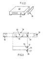
figure 2 est une vue schématique d'une association d'un dispositif selon un second mode de réalisation de l'invention avec un appareil audiovisuel ; et - la
figure 3 est une vue schématique de face, de dessus et de côté du dispositif de commande de lafigure 2 .
- the
figure 1 is a schematic view of a control device according to a first embodiment of the invention; - the
figure 2 is a schematic view of an association of a device according to a second embodiment of the invention with an audiovisual apparatus; and - the
figure 3 is a schematic front, top and side view of the control device of thefigure 2 .
Sur la
Dans le premier exemple de réalisation décrit ici, le premier appareil 3 est un lecteur DVD et le second appareil 9 est un téléviseur.In the first embodiment described here, the
La télécommande 7 est "associée" au second appareil 9 (téléviseur) dans le sens où elle est configurée en usine pour commander à distance, par la transmission de signaux de commande infrarouges, le second appareil 9 (téléviseur) et fournie avec ce dernier lors de sa distribution. Le second appareil 9 (téléviseur) comprend de façon classique des moyens de réception infrarouge 13, adaptés pour recevoir des signaux infrarouges de commande transmis par la télécommande 7.The remote control 7 is "associated" with the second device 9 (television) in the sense that it is configured at the factory to remotely control, by the transmission of infrared control signals, the second device 9 (television) and supplied with the latter. of its distribution. The second apparatus 9 (television) conventionally comprises infrared reception means 13, adapted to receive infrared control signals transmitted by the remote control 7.
Le lecteur DVD 3 est doté de fonctions usuelles relatives à l'utilisation d'un disque DVD : navigation dans un menu associé à un contenu, tel qu'un film enregistré sur le disque DVD, sélection d'éléments dans ce menu (paramètres de configuration du contenu, chapitres de ce contenu, etc.), commandes relatives à la lecture du disque DVD (lecture, pause, avance/retour, arrêt, éjection, etc.), etc.The
Le dispositif 1 de commande du premier appareil 3 (lecteur DVD dans l'exemple cité) comporte des moyens de réception 5 de signaux de commande infrarouges en provenance de la télécommande 7 ainsi que des moyens de pilotage 8 des fonctions du premier appareil 3 en fonction des signaux de commande reçus. Les moyens de pilotage 8 sont adaptés pour générer des signaux de pilotage des fonctions du premier appareil 3 (lecteur DVD), en fonction des signaux de commande reçus par les moyens de réception 5 et provenant de la télécommande 7 associée au second appareil 9 (téléviseur).The device 1 for controlling the first device 3 (DVD player in the example cited) comprises means 5 for receiving infrared control signals from the remote control 7 as well as means 8 for controlling the functions of the
Les signaux de pilotage sont transmis au premier appareil 3 (lecteur DVD) par des moyens de transmission bien connus de l'homme du métier. Par exemple, les moyens de pilotage 8 peuvent commander une diode infrarouge positionnée dans un angle de réception d'un détecteur infrarouge du premier appareil 3 (lecteur DVD). Dans ce cas, la diode commandée par les moyens de pilotage 8 est adaptée pour émettre des signaux de commande infrarouges aptes à être interprétés par le premier appareil 3. En variante, les moyens de transmission entre le dispositif de commande 1 et le premier appareil 3 (lecteur DVD) peuvent être des moyens filaires.The control signals are transmitted to the first device 3 (DVD player) by transmission means well known to those skilled in the art. For example, the control means 8 can control an infrared diode positioned in an angle of reception of an infrared detector of the first device 3 (DVD player). In this case, the diode controlled by the control means 8 is adapted to emit infrared control signals capable of being interpreted by the
En toute hypothèse, les moyens de pilotage 8 sont adaptés pour transcoder une commande reçue de la télécommande 7 et ayant un codage adapté à sa réception par le second appareil 9 (téléviseur) en une commande comprise par le premier appareil 3.In any event, the control means 8 are adapted to transcode a command received from the remote control 7 and having a coding adapted to its reception by the second device 9 (television) into a command understood by the
La télécommande 7 utilise les normes habituelles pour ce type d'appareil, à savoir, le protocole RC5 ou le protocole RECS80, par exemple. Les moyens 5 de réception de signaux de commande sont donc paramétrables de façon à être aptes à comprendre, c'est-à-dire à interpréter, les signaux émis par la télécommande 7. Ce paramétrage est réalisé classiquement comme pour les télécommandes universelles, par sélection dans une base de données pouvant être mise à jour ou non, et/ou par apprentissage.The remote control 7 uses the usual standards for this type of device, namely, the RC5 protocol or the RECS80 protocol, for example. The
Le dispositif de commande 1 comporte également des moyens 11 d'inhibition des moyens 13 de réception des signaux de commande infrarouges du second appareil 9. Dans l'exemple particulier décrit ici, ces moyens d'inhibition 11 comportent des moyens de commande d'une source d'émission infrarouge 15 adaptée et positionnée de manière à saturer les moyens de réception infrarouge 13 du second appareil 9. Par saturation, on entend que, en fonctionnement, la source infrarouge 15 émet une lumière infrarouge continue avec une intensité suffisante pour empêcher les moyens de réception 13 de capter les signaux en provenance de la télécommande 7.The control device 1 also comprises means 11 for inhibiting the
En fonctionnement, les moyens d'inhibition 11 sont activés ou désactivés par des moyens d'activation 17 à la réception d'un signal infrarouge de basculement prédéterminé, provenant de la télécommande 7, comme cela sera explicité dans la description qui suit du fonctionnement du dispositif de commande 1.In operation, the inhibiting
Le dispositif de commande 1 comporte également des moyens de commande 18 de l'affichage du téléviseur 9 ainsi que des moyens 19 de commande de l'alimentation électrique de celui-ci.The control device 1 also comprises control means 18 of the television display 9 as well as means 19 for controlling the power supply thereof.
Le fonctionnement du dispositif de commande 1 est le suivant.The operation of the control device 1 is as follows.
Le dispositif de commande 1 a deux modes opérationnels : un mode désactivé et un mode activé.The control device 1 has two operational modes: a deactivated mode and an activated mode.
Lorsque le dispositif de commande 1 est en mode désactivé, la source d'émission infrarouge 15 n'émet pas de lumière infrarouge. La télécommande 7, associée au second appareil 9 (téléviseur), remplit alors son rôle de commande à distance du second appareil 9 (téléviseur). Lorsque le dispositif de commande 1 est en mode activé, la source d'émission infrarouge 15 émet de lumière infrarouge de manière à inhiber le récepteur infrarouge du second appareil (téléviseur) 9 et la télécommande 7 a alors pour rôle de commander à distance le premier appareil 3 (téléviseur).When the controller 1 is in the off mode, the
Prenons l'hypothèse initiale où le dispositif de commande 1 est en mode désactivé, la télécommande 7 ayant pour rôle de commander à distance le second appareil 9 (téléviseur). Lorsqu'un utilisateur souhaite utiliser la télécommande 7 pour commander à distance le premier appareil 3 (lecteur DVD), à la place du second appareil 9 (téléviseur), autrement dit faire basculer la télécommande 7 du second appareil 9 vers le premier appareil 3, il appuie sur un bouton spécifique de la télécommande 7, par exemple sur le bouton "1" de façon prolongée. La télécommande 7 génère alors un signal infrarouge de commande prédéterminé, que l'on appellera par la suite "signal de basculement".Let us assume the initial hypothesis where the control device 1 is in deactivated mode, the remote control 7 having the role of remotely controlling the second device 9 (television). When a user wishes to use the remote control 7 to remote control the first device 3 (DVD player), instead of the second device 9 (television), in other words to switch the remote control 7 of the second device 9 to the
A la réception de ce signal de basculement par le dispositif de commande 1, celui-ci bascule en mode activé. Dans ce mode, les moyens d'activation 17 activent les moyens d'inhibition 11. Une fois activés, les moyens d'inhibition 11 commandent l'émission de signaux infrarouges par la source 15 en direction des moyens de réception infrarouge 13 du second appareil 9 (téléviseur). A partir de cet instant, le second appareil 9 (téléviseur) n'est plus capable de recevoir de signaux de commande en provenance de la télécommande 7. Les signaux de commande émis par la télécommande 7 sont captés par les moyens de réception 5 et utilisés par le dispositif de commande 1 pour émettre des signaux de pilotage du premier appareil 3.On receipt of this tilt signal by the control device 1, it switches to activated mode. In this mode, the activation means 17 activate the inhibition means 11. Once activated, the inhibition means 11 control the emission of infrared signals by the
Lorsque l'utilisateur souhaite à nouveau utiliser la télécommande 7 pour commander à distance le second appareil 9 (téléviseur), autrement dit, faire basculer la télécommande 7 du premier appareil 3 vers le second appareil 9, il appuie de nouveau sur le bouton spécifique de la télécommande 7, en l'espèce sur le bouton "1" de façon prolongée. La télécommande 7 génère alors un nouveau signal infrarouge de basculement, destiné à faire basculer la télécommande 7 du second appareil 9 vers le premier appareil 3. A la réception de ce nouveau signal de basculement, les moyens d'activation 17 désactivent les moyens d'inhibition 11. Le dispositif de commande 1 bascule ainsi en mode désactivé. Il en résulte que la source d'émission 15 cesse d'émettre des signaux infrarouges de sorte que les moyens de réception 13 du second appareil (téléviseur) cessent d'être saturés. A partir de cet instant, le second appareil 9 redevient capable de recevoir des signaux de commande infrarouges en provenance de la télécommande 7.When the user wishes to use the remote control 7 again to remotely control the second device 9 (television), in other words, to switch the remote control 7 from the
Il est à noter que lorsque le dispositif de commande 1 est connecté à un téléviseur comme, dans le cas présent, par les moyens de commande 18, ou bien s'il possède un affichage propre tel qu'un écran LCD, le moment de basculement peut être "matérialisé" visuellement par une animation appropriée concrétisant l'effet de l'appui sur la touche provoquant le basculement de commande d'un appareil à l'autre.It should be noted that when the control device 1 is connected to a television set, as in the present case, by the control means 18, or if it has a clean display such as an LCD screen, the switching moment can be "materialized" visually by an appropriate animation concretizing the effect of pressing the key causing the switch control from one device to another.
Dans la description qui précède, c'est le même signal de basculement qui est utilisé pour faire basculer la télécommande du second appareil vers le premier et inversement du premier vers le second appareil. En variante, on pourrait envisager d'utiliser deux signaux de basculement différents pour ces deux basculements respectifs, pouvant être générés par des appuis sur deux boutons différents de la télécommande 7.In the above description, it is the same tilt signal that is used to switch the remote control of the second device to the first and vice versa from the first to the second device. Alternatively, one could consider using two different tilt signals for these two respective tilts, which can be generated by pressing two different buttons on the remote control 7.
On va maintenant décrire une forme de réalisation particulière du dispositif de commande de l'invention en référence aux
Le boîtier 34 a la forme d'un parallélépipède rectangle pouvant se placer indifféremment contre une face d'un appareil 20, en l'espèce un lecteur DVD, par une face d'appui 25. Bien entendu, l'appareil 20 pourrait être un autre appareil apte à être télécommandé, tel qu'un home cinéma ou un récepteur satellite. Ces appareils ont pour caractéristique d'avoir la forme d'un parallélépipède d'une profondeur approximativement comprise entre 20 et 35 cm.The
L'appareil 20 est associé à une télécommande infrarouge, non représentée, et doté d'un récepteur infrarouge 22, positionné en façade.The
Le boîtier 34 inclut des fonctions de télévision sur IP, de type "set-top box", et est adapté pour inhiber le récepteur infrarouge 22 de l'appareil 20.The
En comparaison avec le mode de réalisation décrit précédemment, dans ce mode de réalisation, le dispositif de commande 1 et le premier appareil 3 sont intégrés dans un seul boîtier 34.In comparison with the embodiment described above, in this embodiment, the control device 1 and the
Le boîtier 34 comporte, sur l'une des grandes faces du parallélépipède, des aimants 24, représentés sur la
Ainsi, en fonction de l'emplacement du récepteur infrarouge 22 de l'appareil 20, il est facile de positionner le boîtier 34 au plus près de ce récepteur 22.Thus, depending on the location of the
En référence à la
une diode infrarouge 26, jouant le rôle de source d'émission infrarouge destinée à inhiber le récepteur infrarouge de l'appareil 20,un récepteur infrarouge 30, destiné à recevoir des signaux infrarouge en provenance de la télécommande 7,- des moyens d'activation, non représentés,
- des moyens d'inhibition, non représentés, destinés à être activés et désactivés par les moyens d'activation.
- an
infrared diode 26 acting as an infrared emission source for inhibiting the infrared receiver of theapparatus 20, - an
infrared receiver 30 for receiving infrared signals from the remote control 7, - activation means, not shown,
- inhibition means, not shown, intended to be activated and deactivated by the activation means.
Les moyens listés ci-dessus sont analogues à ceux du dispositif de commande 1, précédemment décrit en référence à la
La diode infrarouge 26, chargée d'inhiber le récepteur infrarouge 22 de l'appareil 20, est positionnée derrière un orifice 27 du boîtier 34 sur un épaulement 28. Cet orifice est percé en biais et ainsi conformé pour diriger la lumière infrarouge émise par la diode 26 vers la façade de l'appareil 20, sur laquelle se trouve le récepteur infrarouge 22. Grâce à cela, on minimise le risque de réflexion de la lumière infrarouge émise par la diode 26 vers le récepteur infrarouge 30 du boîtier 34, lequel est placé en façade de ce boîtier 34 comme représenté sur la
Il est à noter que l'épaulement 28 sert également à assurer une adhérence plus efficace du boîtier 34 à l'appareil 20 notamment en cas d'insertion d'une clé USB dans la façade du boîtier 34. Le boîtier 34 comporte également en façade arrière une connectique 32 permettant l'alimentation du boîtier 34, et comportant également dans l'exemple particulier décrit ici une prise d'entrée vidéo pour une connexion vers la sortie du lecteur DVD, une prise de sortie vidéo vers un téléviseur et une prise réseau Ethernet vers un modem routeur internet.It should be noted that the
Après positionnement du boîtier 34 contre l'appareil 20 et connexion des différentes prises, le fonctionnement du boîtier 34 est le suivant.After positioning the
Pour rappel, dans l'exemple décrit ici, l'appareil 20 est un lecteur de DVD. Pour que l'utilisateur puisse utiliser la télécommande de ce lecteur de DVD 20 pour piloter les fonctions de télévision sur IP du boîtier 34, il commence par apparier classiquement cette télécommande avec le boîtier 34, soit en utilisant une base de données, soit par apprentissage. Pour guider l'utilisateur, le boîtier 34 utilise sa connexion au téléviseur pour afficher différents menus classiques de paramétrage.As a reminder, in the example described here, the
Durant cette étape d'appariement, pour éviter toute interférence, le lecteur de DVD 20 est de préférence éteint.During this pairing step, to avoid any interference, the
Puis l'utilisateur allume le lecteur de DVD 20.Then the user turns on the
Suite à un appui prolongé de l'utilisateur sur un bouton spécifique de la télécommande, celle-ci émet un signal de basculement qui, une fois reçu par le boîtier 34, provoque l'activation des moyens d'inhibition de celui-ci. La diode 26 émet alors de la lumière infrarouge qui sature le récepteur 22 du lecteur DVD 20, Le lecteur de DVD 20 n'est alors plus capable de recevoir de commandes infrarouges émises par sa télécommande. Les commandes émises par cette télécommande sont destinées à piloter le boîtier de télévision sur IP. Visuellement, cela se traduit par l'affichage sur l'écran du téléviseur d'un menu spécifique à la télévision sur IP.Following a prolonged pressing of the user on a specific button of the remote control, it emits a tilt signal which, once received by the
Dans cette étape, les boutons de la télécommande sont utilisés pour se déplacer dans un applicatif de télévision sur IP.In this step, the buttons on the remote control are used to move around in an IPTV application.
Suite à un nouvel appui prolongé de l'utilisateur sur le même bouton spécifique de la télécommande, celle-ci émet un nouveau signal de basculement qui, une fois reçu par le boîtier 34, provoque cette fois la désactivation des moyens d'inhibition. La diode 26 cesse alors d'émettre de la lumière infrarouge. Dès lors, l'applicatif de télévision sur IP ne reçoit plus de commandes alors que le lecteur de DVD 20 reçoit à nouveau les commandes en provenance de la télécommande.Following a further prolonged pressing of the user on the same specific button of the remote control, it emits a new tilt signal which, once received by the
Ainsi, l'utilisateur peut à sa guise utiliser le lecteur de DVD ou les fonctions de télévision sur IP du boîtier 34 avec la même télécommande.Thus, the user can at will use the DVD player or the IPTV functions of the
On a donc créé avantageusement une « télécommande universelle » à moindre coût puisqu'on réutilise une télécommande déjà en possession de l'utilisateur pour commander un nouvel appareil, ici un boîtier de télévision sur IP. Et de plus, le boîtier de télévision sur IP peut être vendu à moindre coût puisqu'il n'a pas à fournir, lui aussi, une nouvelle télécommande.It has therefore advantageously created a "universal remote" cheaply since it reuses a remote already in possession of the user to control a new device, here an IPTV box. And, moreover, the IPTV box can be sold cheaply since it does not have to provide, too, a new remote control.
De nombreuses variantes du dispositif sont possibles.Many variants of the device are possible.
Ainsi, comme noté dans l'exemple illustratif ci-dessus, le dispositif de commande est intégrable dans le boîtier d'une fonction audiovisuelle particulière telle que, par exemple, un lecteur de DVD, un récepteur satellite, un récepteur de télévision sur IP, etc.Thus, as noted in the illustrative example above, the control device is integrable in the case of a particular audiovisual function such as, for example, a DVD player, a satellite receiver, an IPTV receiver, etc.
Il est également possible de prévoir que les moyens d'inhibition soient capables d'inhiber les moyens de réception de commande infrarouge d'une pluralité d'appareils. Par exemple, la source d'infrarouge peut être orientée de telle sorte qu'elle illumine plusieurs récepteurs en même temps. On comprend que, dans ce cas, la totalité des appareils illuminés sont alors inhibés en même temps.It is also possible to provide that the inhibiting means are capable of inhibiting the infrared control receiving means of a plurality of devices. For example, the infrared source can be oriented so that it illuminates multiple receivers at the same time. It is understood that in this case, all the illuminated devices are then inhibited at the same time.
Il est également possible de prévoir sur le dispositif une pluralité de prises sur lesquelles viennent se connecter par l'intermédiaire d'un fil souple des diodes infrarouges, chaque diode étant positionnée près d'un récepteur d'un appareil particulier. Dans ce mode de réalisation, les moyens d'activation et d'inhibition sont alors avantageusement programmés de telle sorte qu'il soit possible de sélectionner, à un instant donné, un ou plusieurs des appareils à inhiber.It is also possible to provide on the device a plurality of sockets on which are connected by means of a flexible wire infrared diodes, each diode being positioned near a receiver of a particular device. In this embodiment, the activation and inhibition means are then advantageously programmed so that it is possible to select, at a given instant, one or more of the devices to be inhibited.
Comme illustré dans le mode de réalisation décrit ci-dessus, il est particulièrement avantageux de prévoir des moyens de connexion du dispositif à un dispositif d'affichage, par exemple le poste téléviseur, de telle sorte que ce dispositif d'affichage puisse présenter un état du dispositif de commande et en particulier des moyens d'inhibition. Par exemple, une signalétique, sous forme d'un bandeau en bas d'écran et d'un jeu de couleurs, permet avantageusement à l'utilisateur de déterminer quels sont les appareils qu'il peut commander à cet instant avec sa télécommande et quels sont ceux qui sont inhibés. De façon générale, cela peut permettre d'afficher plusieurs états du dispositif. Par exemple, chaque membre de la famille peut enregistrer des préférences, des liens vers des vidéos à partager, etc. Toutes ces informations sont regroupées sous forme d'une page affichable sur le téléviseur.As illustrated in the embodiment described above, it is particularly advantageous to provide means for connecting the device to a display device, for example the television set, so that this display device can present a state. the control device and in particular inhibition means. For example, a sign, in the form of a strip at the bottom of the screen and a color scheme, advantageously allows the user to determine which devices he can control at this time with his remote control and which are those who are inhibited. In general, this can make it possible to display several states of the device. For example, each family member can save preferences, links to videos to share, and so on. All this information is grouped as a displayable page on the TV.
Selon une autre variante, le dispositif de commande comporte des moyens de commande d'alimentation électrique 19, représentés sur la
L'homme du métier sait également adapter les moyens d'inhibition à une configuration particulière et remplacer, par exemple, l'utilisation d'une diode infrarouge pour inhiber les moyens de réception par un système mécanique, par exemple de volet, ou électronique tel qu'un écran transparent ou opaque en fonction d'une tension appliquée.The person skilled in the art also knows how to adapt the inhibition means to a particular configuration and replace, for example, the use of an infrared diode to inhibit the reception means by a mechanical system, for example a shutter, or an electronic system such as a transparent or opaque screen depending on a voltage applied.
On a ainsi décrit un dispositif de commande qui permet avantageusement de mutualiser la commande de plusieurs appareils autour d'une télécommande standard évitant ainsi, avantageusement, à l'utilisateur l'achat d'une télécommande universelle.A control device has thus been described which advantageously makes it possible to pool the control of several devices around each other. a standard remote thus avoiding, advantageously, the user to purchase a universal remote control.
Claims (7)
Applications Claiming Priority (1)
| Application Number | Priority Date | Filing Date | Title |
|---|---|---|---|
| FR0852104 | 2008-03-31 |
Publications (1)
| Publication Number | Publication Date |
|---|---|
| EP2107802A1 true EP2107802A1 (en) | 2009-10-07 |
Family
ID=39929628
Family Applications (1)
| Application Number | Title | Priority Date | Filing Date |
|---|---|---|---|
| EP09156868A Withdrawn EP2107802A1 (en) | 2008-03-31 | 2009-03-31 | Control device for several items of equipment from an infrared remote control |
Country Status (1)
| Country | Link |
|---|---|
| EP (1) | EP2107802A1 (en) |
Citations (5)
| Publication number | Priority date | Publication date | Assignee | Title |
|---|---|---|---|---|
| EP0612157A2 (en) | 1993-01-06 | 1994-08-24 | Sony Corporation | Method for remotely controlling several audio/visual apparatus |
| WO2000013344A1 (en) | 1998-08-31 | 2000-03-09 | Sony Electronics, Inc. | Optical remote control interface system and method |
| US6570524B1 (en) * | 1999-06-30 | 2003-05-27 | International Business Machines Corp. | Method for remote communication with an addressable target using a generalized pointing device |
| US20030141987A1 (en) * | 1999-06-16 | 2003-07-31 | Hayes Patrick H. | System and method for automatically setting up a universal remote control |
| US20050024226A1 (en) * | 1998-07-23 | 2005-02-03 | Universal Electronics Inc. | Digital interconnect of entertainment equipment |
-
2009
- 2009-03-31 EP EP09156868A patent/EP2107802A1/en not_active Withdrawn
Patent Citations (6)
| Publication number | Priority date | Publication date | Assignee | Title |
|---|---|---|---|---|
| EP0612157A2 (en) | 1993-01-06 | 1994-08-24 | Sony Corporation | Method for remotely controlling several audio/visual apparatus |
| EP0810739A2 (en) * | 1993-01-06 | 1997-12-03 | Sony Corporation | System feature starting method and controlling method for audio/visual system |
| US20050024226A1 (en) * | 1998-07-23 | 2005-02-03 | Universal Electronics Inc. | Digital interconnect of entertainment equipment |
| WO2000013344A1 (en) | 1998-08-31 | 2000-03-09 | Sony Electronics, Inc. | Optical remote control interface system and method |
| US20030141987A1 (en) * | 1999-06-16 | 2003-07-31 | Hayes Patrick H. | System and method for automatically setting up a universal remote control |
| US6570524B1 (en) * | 1999-06-30 | 2003-05-27 | International Business Machines Corp. | Method for remote communication with an addressable target using a generalized pointing device |
Similar Documents
| Publication | Publication Date | Title |
|---|---|---|
| EP2293414A2 (en) | Device for disconnecting at least one appliance from the mains, providing at least one deviating operating mode, configurable device, system and configuration method | |
| EP2695490B1 (en) | Programmable led lighting device and method | |
| FR2902943A1 (en) | Electrical energy saving device i.e. power strip, for e.g. micro-computer, has decision taking unit to maintain on state as long as consumed power is higher than threshold, and turns off apparatuses when power is lesser than threshold | |
| FR2956757A1 (en) | ASSIGNING SCENARIOS TO CONTROL BUTTONS. | |
| WO2001039151A1 (en) | Adaptable remote controller for multipurpose electrical appliances | |
| WO2014195651A1 (en) | Device for managing the illumination of the grips of a climbing wall | |
| EP0732023B1 (en) | Device for switching between a telephone handset and a substitute secondary apparatus | |
| EP2107802A1 (en) | Control device for several items of equipment from an infrared remote control | |
| EP3550537B1 (en) | Wireless control device and assembly comprising such a device, as well as another control device capable of being connected to an electric wire | |
| FR2842371A3 (en) | DEVICE FOR CONTROLLING RADIO AND TELEVISION TERMINALS AND TRANSMITTING / RECEIVING FREQUENCY MODULATION | |
| EP1603250A1 (en) | Print server for power lines | |
| FR2871327A1 (en) | LOCAL AUDIOVISUAL DISTRIBUTION | |
| FR2919097A1 (en) | METHOD OF OPERATING AN ORDER TRANSMITTER IN A DOMOTIC INSTALLATION AND ORDER TRANSMITTER FOR ITS IMPLEMENTATION | |
| EP1722340B1 (en) | Operating procedure for a home automation installation and home automation installation therefor | |
| FR2695238A1 (en) | Method for operating remote control signals, remote control device, and functional units and installation therefor | |
| EP3712083B1 (en) | Electrical system with portable packaging suitable for packaging and transport of at least one micromodule for controlling electrical loads and a bench for pairing | |
| FR2759801A1 (en) | CONTROL SYSTEM BY GRAPHIC DISPLAY OF INFORMATION AVAILABLE ON VIDEO AND / OR AUDIO EQUIPMENT | |
| FR3113802A1 (en) | Connected object equipped with a means of radio communication and an on-board microphone landing in at least two stable positions | |
| EP1253568A2 (en) | Method and apparatus for configuring of remote controllers | |
| FR2950458A1 (en) | DEVICE FOR TRANSMITTING CODES FROM A REMOTE CONTROL | |
| EP4106270A1 (en) | Methods for coupling an electrical appliance, associated systems | |
| FR2944169A1 (en) | Universal digital infrared remote control extender device for digital TV application, has mixer and oscillator to transform envelope signal into infrared remote control signal, and LED to transmit infrared signal to audio/video sources | |
| FR3078413A1 (en) | METHOD FOR OPERATING A MODULE FOR CONTROLLING AN ELECTRICAL CHARGE | |
| FR2819906A1 (en) | INTERACTION DEVICE WITH A MICROCOMPUTER | |
| EP3084548A1 (en) | Management of the operation of a control module |
Legal Events
| Date | Code | Title | Description |
|---|---|---|---|
| PUAI | Public reference made under article 153(3) epc to a published international application that has entered the european phase |
Free format text: ORIGINAL CODE: 0009012 |
|
| AK | Designated contracting states |
Kind code of ref document: A1 Designated state(s): AT BE BG CH CY CZ DE DK EE ES FI FR GB GR HR HU IE IS IT LI LT LU LV MC MK MT NL NO PL PT RO SE SI SK TR |
|
| AX | Request for extension of the european patent |
Extension state: AL BA RS |
|
| 17P | Request for examination filed |
Effective date: 20100308 |
|
| RIC1 | Information provided on ipc code assigned before grant |
Ipc: H04N 5/44 20060101AFI20100325BHEP |
|
| GRAC | Information related to communication of intention to grant a patent modified |
Free format text: ORIGINAL CODE: EPIDOSCIGR1 |
|
| GRAP | Despatch of communication of intention to grant a patent |
Free format text: ORIGINAL CODE: EPIDOSNIGR1 |
|
| AKX | Designation fees paid |
Designated state(s): AT BE BG CH CY CZ DE DK EE ES FI FR GB GR HR HU IE IS IT LI LT LU LV MC MK MT NL NO PL PT RO SE SI SK TR |
|
| STAA | Information on the status of an ep patent application or granted ep patent |
Free format text: STATUS: THE APPLICATION IS DEEMED TO BE WITHDRAWN |
|
| 18D | Application deemed to be withdrawn |
Effective date: 20101001 |