EP2106892A1 - Hotplate for workpieces - Google Patents
Hotplate for workpieces Download PDFInfo
- Publication number
- EP2106892A1 EP2106892A1 EP08006869A EP08006869A EP2106892A1 EP 2106892 A1 EP2106892 A1 EP 2106892A1 EP 08006869 A EP08006869 A EP 08006869A EP 08006869 A EP08006869 A EP 08006869A EP 2106892 A1 EP2106892 A1 EP 2106892A1
- Authority
- EP
- European Patent Office
- Prior art keywords
- heating
- channel
- plate
- channel wall
- contact surface
- Prior art date
- Legal status (The legal status is an assumption and is not a legal conclusion. Google has not performed a legal analysis and makes no representation as to the accuracy of the status listed.)
- Withdrawn
Links
Images

Classifications
-
- B—PERFORMING OPERATIONS; TRANSPORTING
- B29—WORKING OF PLASTICS; WORKING OF SUBSTANCES IN A PLASTIC STATE IN GENERAL
- B29B—PREPARATION OR PRETREATMENT OF THE MATERIAL TO BE SHAPED; MAKING GRANULES OR PREFORMS; RECOVERY OF PLASTICS OR OTHER CONSTITUENTS OF WASTE MATERIAL CONTAINING PLASTICS
- B29B13/00—Conditioning or physical treatment of the material to be shaped
- B29B13/02—Conditioning or physical treatment of the material to be shaped by heating
- B29B13/023—Half-products, e.g. films, plates
-
- B—PERFORMING OPERATIONS; TRANSPORTING
- B30—PRESSES
- B30B—PRESSES IN GENERAL
- B30B15/00—Details of, or accessories for, presses; Auxiliary measures in connection with pressing
- B30B15/06—Platens or press rams
- B30B15/062—Press plates
- B30B15/064—Press plates with heating or cooling means
-
- H—ELECTRICITY
- H05—ELECTRIC TECHNIQUES NOT OTHERWISE PROVIDED FOR
- H05B—ELECTRIC HEATING; ELECTRIC LIGHT SOURCES NOT OTHERWISE PROVIDED FOR; CIRCUIT ARRANGEMENTS FOR ELECTRIC LIGHT SOURCES, IN GENERAL
- H05B6/00—Heating by electric, magnetic or electromagnetic fields
- H05B6/02—Induction heating
- H05B6/10—Induction heating apparatus, other than furnaces, for specific applications
- H05B6/105—Induction heating apparatus, other than furnaces, for specific applications using a susceptor
- H05B6/107—Induction heating apparatus, other than furnaces, for specific applications using a susceptor for continuous movement of material
Landscapes
- Engineering & Computer Science (AREA)
- Mechanical Engineering (AREA)
- Physics & Mathematics (AREA)
- Thermal Sciences (AREA)
- Electromagnetism (AREA)
- Surface Heating Bodies (AREA)
- Lining Or Joining Of Plastics Or The Like (AREA)
- Photovoltaic Devices (AREA)
- General Induction Heating (AREA)
Abstract
Description
Die Erfindung bezieht sich auf eine Heizplatte für Werkstücke mit einem heizbaren Körper, welcher auf einer ersten Seite eine Kontaktfläche für das jeweilige Werkstück aufweist.The invention relates to a heating plate for workpieces with a heatable body, which has a contact surface for the respective workpiece on a first side.
Heizplatten dieser Art werden beispielsweise zum Laminieren von Werkstücken verwendet und in diesem Zusammenhang insbesondere in Laminierpressen zur Herstellung von photovoltaischen Modulen eingesetzt. Beim Laminieren verbindet sich eine dünne, meist folienartige Schicht mit einem Trägermaterial. In vielen Fällen, beispielsweise bei der Herstellung von photovoltaischen Modulen, ist es notwendig, den Laminierprozess bei erhöhten Temperaturen durchzuführen (Heisslaminieren). Dabei wird in der Regel das zu verarbeitende Werkstück (d. h. das mit der zu verbindenden Schicht bedeckte Trägermaterial) an einer auf einer Heizplatte ausgebildeten Kontaktfläche für das Werkstück angeordnet, auf eine vorgegebene Temperatur erwärmt und anschliessend gepresst. Für den Laminierprozess ist es wichtig, dass die Temperaturverteilung an der Kontaktfläche für das jeweilige Werkstück möglichst gleichmässig ist.Heating plates of this type are used for example for laminating workpieces and used in this context, in particular in laminating presses for the production of photovoltaic modules. During lamination, a thin, usually film-like layer combines with a carrier material. In many cases, for example in the production of photovoltaic modules, it is necessary to carry out the laminating process at elevated temperatures (hot lamination). As a rule, the workpiece to be processed (that is to say the carrier material covered with the layer to be bonded) is arranged on a contact surface for the workpiece formed on a heating plate, heated to a predetermined temperature and then pressed. For the lamination process, it is important that the temperature distribution at the contact surface for the respective workpiece is as uniform as possible.
Ein erster Typ von derartigen Heizplatten verfügt über meist stabförmige Heizeinrichtungen, die direkt an einem Heizplattenkörper angebracht sind. Da die Wärme über Wärmeleitung an den Heizplattenkörper abgegeben wird, ist ein möglichst guter Kontakt zwischen den jeweiligen Wärmequellen der Heizeinrichtungen und dem Heizplattenkörper notwendig. Dies wird durch das Einlegen der Heizeinrichtungen in genau gefertigte Nuten erreicht, wobei die Heizeinrichtungen eingeklemmt werden können und die Wärmeleitung durch das Aufbringen von Wärmeleitpaste zusätzlich verbessert werden kann. Allerdings ist es auch im optimalen Fall schwierig, eine gleichmässige Temperaturverteilung über eine grosse Fläche zu erreichen. Das ist nachteilig im Hinblick auf das Laminieren grossflächiger Werkstücke, beispielsweise zur Herstellung von photovoltaischen Modulen, welche eine Fläche von mehr als 1 m2 aufweisen können.A first type of such heating plates has mostly rod-shaped heaters, which are mounted directly on a Heizplattenkörper. Since the heat is discharged via heat conduction to the Heizplattenkörper, the best possible contact between the respective heat sources of the heaters and the Heizplattenkörper is necessary. This is achieved by inserting the heaters in precisely manufactured grooves, the heaters can be clamped and the heat conduction by the application of Thermal compound can be additionally improved. However, it is also difficult in the optimal case to achieve a uniform temperature distribution over a large area. This is disadvantageous with regard to laminating large-area workpieces, for example for the production of photovoltaic modules, which may have an area of more than 1 m 2 .
Bei einem zweiten Typ von Heizplatten, wie er beispielsweise in
In
Ausgehend von dem erwähnten Stand der Technik liegt der Erfindung die Aufgabe zugrunde, die genannten Nachteile zu vermeiden und eine Heizplatte zu schaffen, die mit einer Heizflüssigkeit heizbar ist und es ermöglicht, mit einfachen Mitteln eine möglichst konstante Temperatur an einer Kontaktfläche für das zu heizende Werkstück zu erzielen.Based on the cited prior art, the invention has the object to avoid the disadvantages mentioned and to provide a heating plate which is heated with a heating fluid and makes it possible with simple means a constant temperature as possible at a contact surface for the workpiece to be heated to achieve.
Diese Aufgabe wird durch eine Heizplatte mit den Merkmalen des Anspruchs 1 gelöst.This object is achieved by a heating plate with the features of
Diese Heizplatte umfasst einen heizbaren Körper, welcher auf einer ersten Seite eine Kontaktfläche für das jeweilige Werkstück aufweist, mindestens einen Heizkanal, welcher in oder an dem heizbaren Körper gegenüber der Kontaktfläche ausgebildet ist und mit einer Heizflüssigkeit gefüllt ist, und Heizmittel zum Heizen der Heizflüssigkeit.This heating plate comprises a heatable body which has on a first side a contact surface for the respective workpiece, at least one heating channel, which is formed in or on the heatable body opposite the contact surface and is filled with a heating fluid, and heating means for heating the heating fluid.
Gemäss der Erfindung sind die Heizmittel ausserhalb des Heizkanals angeordnet, wobei Wärme, die mittels der Heizmittel erzeugbar ist, durch eine Kanalwand des jeweiligen Heizkanals in die Heizflüssigkeit einbringbar ist.According to the invention, the heating means are arranged outside the heating channel, whereby heat, which can be generated by means of the heating means, can be introduced into the heating liquid through a channel wall of the respective heating channel.
Dadurch, dass die Heizmittel ausserhalb des jeweiligen Heizkanals angeordnet sind, können die Heizmittel mit relativ wenig Aufwand am heizbaren Körper montiert werden. Dabei schränkt die jeweilige Anordnung bzw. Form des jeweiligen Heizkanals die Wahl der Orte, an denen die jeweiligen Heizmittel am heizbaren Körper platziert werden können, nicht bzw. nicht wesentlich ein, zumal Komplikationen, die mit dem Einbau von Heizmitteln in den jeweiligen Heizkanal verbunden wären, prinzipiell vermieden werden.The fact that the heating means are arranged outside the respective heating channel, the heating means can be mounted with relatively little effort on the heatable body. In this case, the respective arrangement or shape of the respective heating channel limits the choice of locations where the respective heating means can be placed on the heatable body, not or not significantly, especially complications that would be associated with the installation of heating in the respective heating channel , be avoided in principle.
Dadurch, dass die Heizmittel erfindungsgemäss derart angeordnet sind, dass die Wärme, die mittels der Heizmittel erzeugbar ist, durch eine Kanalwand des jeweiligen Heizkanals in die Heizflüssigkeit einbringbar ist, und dadurch, dass der jeweilige Heizkanal gegenüber der Kontaktfläche für das Werkstück angeordnet ist, ist weiterhin gewährleistet, dass Wärmeverluste in der Heizflüssigkeit jeweils nahe an der Kontaktfläche für das Werkstück ausgeglichen werden können. Dadurch ist die Möglichkeit gegeben, eine gleichmässige Temperaturverteilung an der Kontaktfläche zu realisieren.Characterized in that the heating means according to the invention are arranged such that the heat which can be generated by the heating means, is introduced through a channel wall of the respective heating channel in the heating fluid, and in that the respective heating channel is arranged opposite the contact surface for the workpiece is Furthermore, it ensures that heat losses in the heating fluid can be compensated in each case close to the contact surface for the workpiece. This gives the possibility to realize a uniform temperature distribution at the contact surface.
Im Rahmen der Erfindung kann die Temperaturverteilung an der Kontaktfläche durch verschiedene Massnahmen beeinflusst werden. Die Homogenität der Temperaturverteilung an der Kontaktfläche kann beispielsweise durch die räumliche Anordnung des jeweiligen Heizkanals bzw. der jeweiligen Heizkanäle und/oder die räumliche Anordnung der jeweiligen Heizmittel beeinflusst und entsprechend optimiert werden. Die Homogenität der Temperaturverteilung an der Kontaktfläche kann weiterhin durch eine gezielte Beeinflussung der räumlichen Verteilung des jeweiligen Wärmestroms, der in bestimmten Bereichen der jeweiligen Kanalwand in die Heizflüssigkeit eingebracht wird, beeinflusst und entsprechend optimiert werden. Um Temperaturdifferenzen zwischen verschiedenen Orten an der Kontaktfläche zu minimieren bzw. zu kompensieren, können beispielsweise eine Vielzahl von Heizeinrichtungen ausserhalb des jeweiligen Heizkanals bzw. der Heizkanäle angeordnet werden, wobei die Wärmeleistung, welche die einzelnen Heizeinrichtungen durch die jeweiligen Kanalwände an die Heizflüssigkeit abgeben, jeweils von Ort zu Ort variieren kann. Weiterhin können die jeweiligen Heizkanäle so ausgelegt werden, dass eine Zirkulation der Heizflüssigkeit in den jeweiligen Heizkanälen ermöglicht wird, gegebenenfalls erzwungen durch eine Pumpe, die für einen Fluss der Heizflüssigkeit durch die jeweiligen Heizkanäle sorgt. Auch diese Massnahme kann dazu beitragen, eine gleichmässige räumliche Verteilung der Temperatur an der Kontaktfläche zu erzielen.In the context of the invention, the temperature distribution at the contact surface can be influenced by various measures. The homogeneity of the temperature distribution at the contact surface can be influenced, for example, by the spatial arrangement of the respective heating channel or the respective heating channels and / or the spatial arrangement of the respective heating means and optimized accordingly. The homogeneity of the temperature distribution at the contact surface can furthermore be influenced and optimized correspondingly by a targeted influencing of the spatial distribution of the respective heat flow, which is introduced into the heating fluid in specific regions of the respective channel wall. To minimize or compensate for temperature differences between different locations on the contact surface, for example, a plurality of heating devices outside the respective heating channel or the heating channels are arranged, wherein the heat output, which deliver the individual heaters through the respective channel walls to the heating fluid, may vary from place to place. Furthermore, the respective heating channels can be designed so that a circulation of the heating fluid in the respective heating channels is made possible, optionally enforced by a pump which ensures a flow of the heating fluid through the respective heating channels. This measure can also help to achieve a uniform spatial distribution of the temperature at the contact surface.
Die Heizmittel der erfindungsgemässen Heizplatte können auf verschiedene Weisen realisiert werden.The heating means of the heating plate according to the invention can be realized in various ways.
Eine Ausführungsform der Heizplatte weist Heizmittel auf, die mindestens eine Heizeinrichtung mit jeweils mindestens einer an der jeweiligen Kanalwand angeordneten Wärmequelle umfassen, wobei die Heizflüssigkeit durch Wärmeleitung durch die Kanalwand erwärmbar ist. Als Wärmequelle ist beispielsweise eine elektrische Widerstandsheizung geeignet, wobei die Widerstandsheizung in Kontakt mit der Kanalwand gebracht werden kann.An embodiment of the heating plate has heating means which comprise at least one heating device, each with at least one heat source arranged on the respective channel wall, wherein the heating liquid can be heated by heat conduction through the channel wall. As a heat source, for example, an electrical resistance heater is suitable, wherein the resistance heater can be brought into contact with the channel wall.
Bei einer anderen Ausführungsform der Heizplatte ist vorgesehen, dass die jeweilige Kanalwand induktiv erwärmbar ist und die Heizmittel mindestens eine Heizeinrichtung zum induktiven Heizen der Kanalwand umfassen. Um eine induktive Heizung der Kanalwand zu ermöglichen, kann die Kanalwand aus einem elektrisch leitfähigen Material, beispielsweise einem Metall, gefertigt werden. Um die Effizienz der induktiven Heizung der Kanalwand zu optimieren, kann die Kanalwand aus einem magnetisierbaren Material, beispielsweise einem ferromagnetischen Material, insbesondere einem ferromagnetischen Metall wie Eisen oder einer Eisenlegierung (beispielsweise Stahl), gefertigt sein. Die jeweilige Heizeinrichtung zum induktiven Heizen der Kanalwand kann mit konventionellen Mitteln realisiert werden. Diese Heizeinrichtung hat den Vorteil, dass die Heizeinrichtung nicht in Kontakt mit der Kanalwand stehen muss, sondern in einem Abstand zur Kanalwand angeordnet werden kann. Dies vereinfacht die Montage der Heizeinrichtung.In another embodiment of the heating plate is provided that the respective channel wall is inductively heated and the heating means comprise at least one heating device for inductive heating of the channel wall. In order to enable inductive heating of the channel wall, the channel wall can be made of an electrically conductive material, for example a metal. In order to optimize the efficiency of the inductive heating of the channel wall, the channel wall of a magnetizable material, such as a ferromagnetic material, in particular a ferromagnetic metal such as iron or an iron alloy (for example Steel). The respective heating device for inductive heating of the channel wall can be realized by conventional means. This heater has the advantage that the heater does not have to be in contact with the channel wall, but can be arranged at a distance from the channel wall. This simplifies the installation of the heater.
Weitere Einzelheiten der Erfindung und insbesondere beispielhafte Ausführungsformen der Erfindung werden im Folgenden anhand der beigefügten Zeichnungen erläutert. Es zeigen:
- Fig. 1
- einen Querschnitt durch eine erste Ausführungsform der erfindungsgemässen Heizplatte, mit einem heizbaren Körper, einem Heizkanal und Heizmitteln, welche Heizmittel mehrere Heizeinrichtungen mit jeweils einer an einer Kanalwand des Heizkanals angeordneten Wärmequelle umfassen;
- Fig. 2
- einen Querschnitt durch eine zweite Ausführungsform der erfindungsgemässen Heizplatte, welche hinsichtlich der Konstruktion des heizbaren Körpers und des Heizkanals mit der Ausführungsform gemäss
Fig. 1 identisch ist, wobei die Heizmittel allerdings mehrere Heizeinrichtungen zum induktiven Heizen der jeweiligen Kanalwände umfassen; - Fig. 3
- einen Querschnitt durch eine dritte Ausführungsform der erfindungsgemässen Heizplatte, mit Heizmitteln gemäss
Fig. 1 ; - Fig. 4
- einen Querschnitt durch eine vierte Ausführungsform der erfindungsgemässen Heizplatte, mit Heizmitteln gemäss
Fig. 2 ; - Fig. 5
- einen Querschnitt durch eine fünfte Ausführungsform der erfindungsgemässen Heizplatte, mit Heizmitteln gemäss
Fig. 1 ; - Fig. 6
- einen Querschnitt durch eine sechste Ausführungsform der erfindungsgemässen Heizplatte, mit Heizmitteln gemäss
Fig. 2 ; - Fig. 7
- einen Querschnitt durch eine siebte Ausführungsform der erfindungsgemässen Heizplatte, mit Heizmitteln gemäss
Fig. 1 ; - Fig. 8
- einen Querschnitt durch eine achte Ausführungsform der erfindungsgemässen Heizplatte, mit Heizmitteln gemäss
Fig. 2 ; - Fig. 9
- eine perspektivische Ansicht einer neunten Ausführungsform der erfindungsgemässen Heizplatte, dargestellt ohne Heizmittel;
- Fig. 10
- eine perspektivische Ansicht eines Teils einer zehnten Ausführungsform der erfindungsgemässen Heizplatte, dargestellt ohne Heizmittel;
- Fig. 11
- die Ausführungsform gemäss
Fig. 10 , mit Heizmitteln.
- Fig. 1
- a cross-section through a first embodiment of the inventive heating plate, with a heatable body, a heating channel and heating means, which heating means comprise a plurality of heaters each having a arranged on a channel wall of the heating channel heat source;
- Fig. 2
- a cross-section through a second embodiment of the inventive heating plate, which with respect to the construction of the heatable body and the heating channel with the embodiment according to
Fig. 1 is identical, wherein the heating means, however, comprise a plurality of heaters for inductive heating of the respective channel walls; - Fig. 3
- a cross section through a third embodiment of the inventive hot plate, with heating means according to
Fig. 1 ; - Fig. 4
- a cross section through a fourth embodiment of the inventive hot plate, with heating means according to
Fig. 2 ; - Fig. 5
- a cross section through a fifth embodiment of the inventive hot plate, with heating means according to
Fig. 1 ; - Fig. 6
- a cross section through a sixth embodiment of the inventive hot plate, with heating means according to
Fig. 2 ; - Fig. 7
- a cross section through a seventh embodiment of the inventive hot plate, with heating means according to
Fig. 1 ; - Fig. 8
- a cross section through an eighth embodiment of the inventive hot plate, with heating means according to
Fig. 2 ; - Fig. 9
- a perspective view of a ninth embodiment of the inventive hot plate, shown without heating means;
- Fig. 10
- a perspective view of a portion of a tenth embodiment of the inventive hot plate, shown without heating means;
- Fig. 11
- the embodiment according to
Fig. 10 , with heating means.
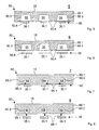
Der Heizkanal 25 ist an der der Kontaktfläche 15 gegenüber liegenden Seite des heizbaren Körpers 20 angeordnet. Um einen möglichst grossen Teil der Oberfläche des heizbaren Körpers in Kontakt mit der im Heizkanal 25 geführten Heizflüssigkeit zu bringen, weist der Heizkanal 25 eine Vielzahl verschiedener Längsabschnitte auf, von denen einige parallel zueinander und andere in einem rechten Winkel zueinander angeordnet sind, wobei die Längsabschnitte derart miteinander verbunden sind, dass die Heizflüssigkeit im Heizkanal 25 längs einer geschlossenen Bahn entlang der Oberfläche des heizbaren Körpers 20 zirkulieren kann.The
Die
Die Heizmittel 30 umfassen mehrere Heizeinrichtungen 30.1 mit jeweils einer Wärmequelle. Als Wärmequelle kann beispielsweise ein elektrischer Widerstand dienen, welcher an eine elektrische Stromquelle angeschlossen ist. Jede Heizeinrichtung 30.1 ist formschlüssig an einer äusseren Seite der Kanalwand 25.1, d.h. ausserhalb des Heizkanals 25, angebracht. Die Heizmittel 30 erlauben es somit, die Kanalwand 25.1 in verschiedenen Bereichen von aussen aufzuheizen. Die Erwärmung der Heizflüssigkeit erfolgt durch Wärmeübergang von der erwärmten Kanalwand 25.1 zur Heizflüssigkeit. Die Wärme, die mittels der Heizmittel 30 erzeugbar ist, ist demnach von den Heizeinrichtungen 30.1 durch die Kanalwand 25.1 des Heizkanals 25 mittels Wärmeleitung in die Heizflüssigkeit einbringbar.The heating means 30 comprise a plurality of heating devices 30.1 each having a heat source. As a heat source, for example, serve an electrical resistance, which is connected to an electrical power source. Each heater 30.1 is positively mounted on an outer side of the channel wall 25.1, ie outside the
Der heizbare Körper 20 kann, wie
Der mehrschichtige Aufbau des heizbaren Körpers 20 ermöglicht insbesondere eine Optimierung hinsichtlich der mechanischen und wärmetechnischen Eigenschaften des Körpers 20. Generell ist es vorteilhaft, wenn die Platte 20.1 und die Schichten 20.2 und 20.3 eine möglichst hohe Wärmeleitfähigkeit und/oder ein möglichst geringes Gewicht aufweisen und/oder kostengünstig herstellbar sind. Die Platte 20.1 kann so ausgelegt werden, dass sie den grössten Teil des Volumens des Körpers 20 einnimmt und die mechanische Stabilität des Körpers 20 gewährleistet. Die Schicht 20.2 kann beispielsweise so ausgelegt werden, dass der heizbare Körper 20 an der Kontaktfläche 15 besonders verschleissfest ausgebildet ist. Die Schicht 20.3 kann wiederum so gewählt werden, dass die Herstellung einer Verbindung zwischen der Kanalwand 25.1 und dem Körper 20, beispielsweise mittels Schweissen, vereinfacht wird.In particular, it is advantageous if the plate 20.1 and the layers 20.2 and 20.3 have the highest possible thermal conductivity and / or the lowest possible weight, and / or or are inexpensive to produce. The plate 20.1 can be designed so that it occupies most of the volume of the
Für den heizbaren Körper 20 an sich und insbesondere für die Platte 20.1 ist Aluminium, aufgrund der guten Wärmeleitfähigkeit und des kleinen Gewichts, der geeignete Werkstoff. Auch die Verwendung von Kupfer ist denkbar. Die Schicht 20.2 kann beispielsweise aus Stahl gefertigt sein, um eine hohe Verschleissfestigkeit zu gewährleisten. Die Schicht 20.3 kann beispielsweise aus Kupfer oder Stahl bestehen. Derartige Schichten 20.2 und 20.3 lassen sich beispielsweise durch Sprengplattieren oder Hochdruckwalzen auf die Platte 20.1 aufbringen. Als geeigneter Werkstoff für die Kanalwand 25.1 kann im vorliegenden Fall beispielsweise Kupfer angesehen werden, um eine hohe Wärmeleitfähigkeit zu gewährleisten.For the
Wie
Die
Die Heizplatte 3 gemäss
Die Abdeckplatte 40.4 kann nach verschiedenen Verfahren mit der Platte 40.1 verbunden werden, um den Kanal 45 dicht abzuschliessen, beispielsweise mittels Schweissen, Löten oder Verfahren zum Plattieren (beispielsweise Sprengplattieren oder Walzen). Die Abdeckplatte 40.4 könnte auch mit konventionellen Befestigungsmitteln wie Schrauben an der Platte 40.1 befestigt werden. In diesem Fall kann es gegebenenfalls nötig sein, den Kanal 45 mit geeigneten Dichtelementen abzudichten. Die Werkstoffe für die Platte 40.1, die Schicht 40.2 und die Abdeckplatte 40.4 können nach denselben (oben genannten) Grundsätzen gewählt werden wie die Werkstoffe für die entsprechenden Teile der Heizplatten 1 und 2 (d.h. Platte 20.1, die Schicht 20.2 und die Kanalwand 25.1) des heizbaren Körpers 20: die Platte 40.1 könnte beispielsweise aus Aluminium oder Kupfer, die Schicht 40.2 aus Stahl und die Abdeckplatte 40.4 aus Kupfer gefertigt werden.The cover plate 40.4 may be connected to the plate 40.1 by various methods to seal the
Die Heizplatte 4 gemäss
Die Heizplatte 5 gemäss
Wie
Im Falle der Heizplatte 6 gemäss
Die Heizplatte 7 gemäss
Die Abdeckplatten 71 unterscheiden sich von den Abdeckplatten 50.4 dadurch, dass die Abdeckplatten 71 mehrschichtig aufgebaut sind. Wie
Der mehrschichtige Aufbau der Abdeckplatten 71 ermöglicht es, durch geeignete Wahl der Werkstoffe für die verschiedenen Schichten, die Eigenschaften der Abdeckplatten 71 nach verschiedenen Gesichtspunkten zu optimieren. Der Werkstoff der jeweiligen Schicht 71.2 muss beispielsweise nicht unbedingt mittels Schweissen mit dem Werkstoff der Platte 70.1 verbindbar sein, zumal - wie erwähnt - im vorliegenden Fall eine belastbare Verbindung zwischen einer der Abdeckplatten 71 und der Platte 70.1 über eine Verbindung zwischen dem jeweiligen tragenden Teil 71.1 und der Platte 70.1 realisiert werden kann. Der Werkstoff der jeweiligen Schicht 71.2 kann hingegen beispielsweise so gewählt werden, dass die jeweilige Schicht 71.2 im Hinblick auf induktives Aufheizen optimiert ist. Dementsprechend kann die jeweilige Schicht 71.2 aus einem elektrisch leitfähigen Material, beispielsweise aus einem Metall, und/oder aus einem magnetisierbaren Material, beispielsweise einem ferromagnetischen Material, insbesondere einem ferromagnetischen Metall wie Eisen oder einer Eisenlegierung (beispielsweise Stahl), gefertigt sein kann.The multilayer structure of the
Die tragenden Teile 71.1 müssen nicht unbedingt gleichmässig mit der Schicht 71.2 bedeckt sein. Wie
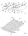
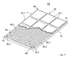
Der heizbare Körper 80 besteht aus einer Platte 80.1, in der auf einer Seite eine meanderförmig ausgebildete Nut 80.3 ausgebildet ist, und einer Abdeckplatte 81, welche die Nut 80.3 auf der der Kontaktfläche 15 gegenüber liegenden Seite abdeckt und dicht abschliesst. Der Heizkanal 85 ist dabei in der Nut 80.3 ausgebildet und jeweils durch die Platte 80.1 und die Abdeckplatte 81 begrenzt. Diejenigen Bereiche der Abdeckplatte 81, die den Heizkanal 85 begrenzen, können jeweils als "Kanalwand" im Sinne der Definition der Erfindung angesehen werden.The
Der Heizkanal 85 ist zusammengesetzt aus einer Vielzahl von Längsabschnitten, die miteinander verbunden sind und relativ zueinander entweder in einem rechten Winkel zueinander oder parallel nebeneinander angeordnet sind, wobei jeweils nebeneinander angeordneten Längsabschnitte des Heizkanals 85 durch eine Trennwand 85.1 getrennt sind. Der Heizkanal 85 weist ein erstes Kanalende 85.2 und ein zweites Kanalende 85.3 auf, wobei am ersten Kanalende 85.2 eine Eingangsöffnung 86 für die Heizflüssigkeit und am zweiten Kanalende 85.3 eine Ausgangsöffnung 87 für die Heizflüssigkeit angeordnet ist. Die Ausgangsöffnung 87 ist im Betrieb der Heizplatte 10 derart mittels einer (in
Wie
Zum Heizen der Heizflüssigkeit sind im vorliegenden Beispiel die Heizmittel 30 mit mehreren Heizeinrichtungen 30.1 vorgesehen. Die Heizeinrichtungen 30.1 sind an der Oberfläche der Abdeckplatte 81 nahezu flächendeckend angeordnet. Die Grösse der Heizeinrichtungen 30.1 ist dabei so bemessen, dass die Abdeckplatte 81 in jeder von zwei Dimensionen jeweils von mehreren Heizeinrichtungen 30.1 bedeckt wird.For heating the heating fluid, the heating means 30 are provided with a plurality of heaters 30.1 in the present example. The heaters 30.1 are arranged almost completely on the surface of the
Durch diese flächendeckende Anordnung der Heizeinrichtungen 30.1 in zwei Dimensionen wird beispielsweise erreicht, dass mehrere Heizeinrichtungen 30.1 an der jeweiligen Kanalwand über mehrere Bereiche der Kanalwand verteilt angeordnet sind, wobei jeweils verschiedene Bereiche der Kanalwand mit jeweils verschiedenen Heizeinrichtungen 30.1 beheizbar sind.As a result of this comprehensive arrangement of the heating devices 30.1 in two dimensions, it is achieved, for example, that a plurality of heating devices 30.1 are distributed on the respective channel wall over a plurality of regions of the channel wall, whereby different regions of the channel wall can each be heated with respective different heating devices 30.1.
Weiterhin kann erreicht werden, dass eine einzelne Heizeinrichtung 30.1 (bedingt durch den von dieser Heizeinrichtung ausgehenden Wärmestrom) die Heizflüssigkeit gleichzeitig in einer Mehrzahl von (beispielsweise nebeneinander angeordneten) Abschnitten des Heizkanals 85 aufheizen kann, indem der von einer einzelnen Heizeinrichtung 30.1 ausgehende Wärmestrom gleichzeitig über mehrere nebeneinander angeordneten Längsabschnitte des Heizkanals 85 verteilt in die Heizflüssigkeit eingeleitet wird.Furthermore, it can be achieved that a single heating device 30.1 (due to the heat flow emanating from this heating device) can simultaneously heat the heating fluid in a plurality of (for example juxtaposed) sections of the
Durch die vorstehend genannten Massnahmen können lokale Wärmeverluste, die in der Heizflüssigkeit beim Strömen durch den Heizkanal 85 auftreten können, ausgeglichen werden.By means of the above-mentioned measures, it is possible to compensate for local heat losses that may occur in the heating fluid when flowing through the
Weiterhin besteht die Möglichkeit, die Heizleistungen (Wärmeströme) der jeweiligen Heizeinrichtungen 30.1 jeweils unabhängig voneinander zu regulieren. Auf diese Weise können die Wärmeströme, die von verschiedenen Heizeinrichtungen 30.1 durch die Abdeckplatte 81 in die Heizflüssigkeit eingeleitet werden, in zwei Dimensionen abhängig von dem jeweiligen Ort kontrolliert werden. Um die von den Heizeinrichtungen 30.1 ausgehenden Wärmeströme so zu steuern, dass an der Kontaktfläche 15 eine vorgegebene Temperaturverteilung erzielt wird, ist es weiterhin möglich, die momentane Temperaturverteilung mit Sensoren zu messen und, falls Abweichungen zwischen der momentanen Temperaturverteilung und der vorgegebenen Temperaturverteilung auftreten, diese Abweichungen durch eine Steuerung der jeweils von einer der Heizeinrichtungen 30.1 ausgehenden Wärmeströme zu beseitigen oder wenigstens zu minimieren.Furthermore, it is possible to independently regulate the heating powers (heat flows) of the respective heating devices 30.1. In this way, the heat flows, which are introduced by different heaters 30.1 through the
Der Heizkanal 85 der Heizplatte 10 kann im Rahmen der Erfindung ohne weiteres modifiziert werden: Er könnte beispielsweise durch mehrere Kanalabschnitte, die zueinander parallel geschaltet sind oder verzweigt sind, oder durch mehrere getrennte Heizkanäle ersetzt werden.The
Weiterhin können im Falle der Heizplatte 10 die Heizmittel 30 durch Heizmittel 35 mit mehreren Heizeinrichtungen 35.1 zum induktiven Heizen ersetzt werden, wobei jede Heizeinrichtung 35.1 die Abdeckplatte 81 im Bereich mehrerer (nebeneinander angeordneter) Längsabschnitte des Heizkanals induktiv 85 aufheizen kann.Furthermore, in the case of the
Claims (13)
mit einem heizbaren Körper (20, 40, 50, 60, 70, 80), welcher auf einer ersten Seite eine Kontaktfläche (15) für das jeweilige Werkstück aufweist,
mit mindestens einem mit einer Heizflüssigkeit gefüllten Heizkanal (25, 45, 55, 65, 75, 85), welcher in oder an dem heizbaren Körper (20, 40, 50, 60, 70, 80) gegenüber der Kontaktfläche (15) ausgebildet ist, und
mit Heizmitteln (30, 35) zum Heizen der Heizflüssigkeit,
dadurch gekennzeichnet, dass
die Heizmittel (30, 35) ausserhalb des jeweiligen Heizkanals (25, 45, 55, 65, 75, 85) angeordnet sind, wobei Wärme, die mittels der Heizmittel (30, 35) erzeugbar ist, durch eine Kanalwand (25.1, 45.1, 50.4, 65.1, 71, 81) des jeweiligen Heizkanals in die Heizflüssigkeit einbringbar ist.Heating plate (1, 2, 3, 4, 5, 6, 7, 8, 9, 10) for workpieces,
with a heatable body (20, 40, 50, 60, 70, 80), which on a first side has a contact surface (15) for the respective workpiece,
with at least one heating channel (25, 45, 55, 65, 75, 85) filled with a heating fluid, which is formed in or on the heatable body (20, 40, 50, 60, 70, 80) opposite the contact surface (15) , and
with heating means (30, 35) for heating the heating fluid,
characterized in that
the heating means (30, 35) are arranged outside the respective heating channel (25, 45, 55, 65, 75, 85), whereby heat which can be generated by means of the heating means (30, 35) is conveyed through a channel wall (25.1, 45.1, 50.4, 65.1, 71, 81) of the respective heating channel can be introduced into the heating fluid.
die Heizmittel (30) mindestens eine Heizeinrichtung (30.1) mit jeweils mindestens einer an der Kanalwand (25.1, 45.1, 50.4, 65.1, 81) angeordneten Wärmequelle umfassen und
die Heizflüssigkeit durch Wärmeleitung durch die Kanalwand (25.1, 45.1, 50.4, 65.1, 81) erwärmbar ist.Heating plate (1, 3, 5, 7, 10) according to claim 1, wherein
the heating means (30) comprise at least one heating device (30.1) each having at least one heat source arranged on the channel wall (25.1, 45.1, 50.4, 65.1, 81) and
the heating fluid can be heated by heat conduction through the duct wall (25.1, 45.1, 50.4, 65.1, 81).
der heizbare Körper (20, 40) mehrere Schichten (20.1, 20.2, 20.3, 40.1, 40.2) aufweist und mindestens eine der Schichten (20.1, 40.1) aus Kupfer oder Aluminium besteht.Heating plate (1, 2, 3, 4) according to any one of claims 1-3, wherein
the heatable body (20, 40) has a plurality of layers (20.1, 20.2, 20.3, 40.1, 40.2) and at least one of the layers (20.1, 40.1) consists of copper or aluminum.
der heizbare Körper (40, 80) mehrere nebeneinander angeordnete Nuten und/oder mehrere nebeneinander angeordnete Abschnitte einer Nut (40.3, 80.3) aufweist und die Abdeckplatte (40.4, 81) die nebeneinander angeordneten Nuten und/oder die nebeneinander angeordneten Abschnitte der einen Nut (40.3, 80.3) abdeckt, und
wobei die jeweilige Nut (40.3, 80.3) jeweils einen Heizkanal (45, 85) begrenzt und die Abdeckplatte (40.4, 81) derart am heizbaren Körper (40, 80) befestigt ist, dass die Abdeckplatte (40, 80) mehrere nebeneinander angeordnete Heizkanäle und/oder mehrere nebeneinander angeordnete Abschnitte eines Heizkanals (45, 85) dicht abschliesst.A heating plate (3, 4, 10) according to claim 7, wherein
the heatable body (40, 80) has a plurality of juxtaposed grooves and / or a plurality of juxtaposed sections of a groove (40.3, 80.3) and the cover plate (40.4, 81) the juxtaposed grooves and / or the juxtaposed sections of a groove ( 40.3, 80.3), and
wherein the respective groove (40.3, 80.3) in each case defines a heating channel (45, 85) and the cover plate (40.4, 81) is fastened to the heatable body (40, 80) such that the cover plate (40, 80) has a plurality of heating channels arranged side by side and / or several juxtaposed sections of a heating channel (45, 85) tightly closes.
Priority Applications (5)
| Application Number | Priority Date | Filing Date | Title |
|---|---|---|---|
| EP08006869A EP2106892A1 (en) | 2008-04-04 | 2008-04-04 | Hotplate for workpieces |
| EP09405058A EP2106891A1 (en) | 2008-04-04 | 2009-03-31 | Hotplate for workpieces |
| CN200910128393.3A CN101549570B (en) | 2008-04-04 | 2009-04-02 | Hotplate for workpieces |
| JP2009091263A JP5420296B2 (en) | 2008-04-04 | 2009-04-03 | Heating plate for workpiece |
| US12/384,399 US8575524B2 (en) | 2008-04-04 | 2009-04-03 | Heating plate for workpieces |
Applications Claiming Priority (1)
| Application Number | Priority Date | Filing Date | Title |
|---|---|---|---|
| EP08006869A EP2106892A1 (en) | 2008-04-04 | 2008-04-04 | Hotplate for workpieces |
Publications (1)
| Publication Number | Publication Date |
|---|---|
| EP2106892A1 true EP2106892A1 (en) | 2009-10-07 |
Family
ID=39744853
Family Applications (2)
| Application Number | Title | Priority Date | Filing Date |
|---|---|---|---|
| EP08006869A Withdrawn EP2106892A1 (en) | 2008-04-04 | 2008-04-04 | Hotplate for workpieces |
| EP09405058A Withdrawn EP2106891A1 (en) | 2008-04-04 | 2009-03-31 | Hotplate for workpieces |
Family Applications After (1)
| Application Number | Title | Priority Date | Filing Date |
|---|---|---|---|
| EP09405058A Withdrawn EP2106891A1 (en) | 2008-04-04 | 2009-03-31 | Hotplate for workpieces |
Country Status (4)
| Country | Link |
|---|---|
| US (1) | US8575524B2 (en) |
| EP (2) | EP2106892A1 (en) |
| JP (1) | JP5420296B2 (en) |
| CN (1) | CN101549570B (en) |
Cited By (1)
| Publication number | Priority date | Publication date | Assignee | Title |
|---|---|---|---|---|
| WO2023186217A1 (en) * | 2022-03-29 | 2023-10-05 | Pva Industrial Vacuum Systems Gmbh | High-temperature joining furnace |
Families Citing this family (9)
| Publication number | Priority date | Publication date | Assignee | Title |
|---|---|---|---|---|
| JP5173921B2 (en) * | 2008-06-18 | 2013-04-03 | 京セラ株式会社 | Solar cell module laminator |
| CN102825940B (en) * | 2012-08-30 | 2015-07-08 | 郑州玉海玻璃技术有限公司 | Novel manufacturing method and processing equipment for oversized flat glass pattern |
| DE102014006482A1 (en) * | 2013-12-02 | 2015-06-03 | Harburg-Freudenberger Maschinenbau Gmbh | Method for producing a heating plate for a tire press |
| CN107225221A (en) * | 2017-07-21 | 2017-10-03 | 四川省祥业机械铸造有限公司 | A kind of crankcase gap bridge cover plate running gate system |
| US11131464B2 (en) * | 2018-04-06 | 2021-09-28 | Hall Labs Llc | Hydronic panel heating or cooling system |
| CN108859370A (en) * | 2018-06-08 | 2018-11-23 | 北京汉能光伏投资有限公司 | A kind of heating plate and laminater |
| CN112127214A (en) * | 2020-10-22 | 2020-12-25 | 和煦(上海)环保科技有限公司 | Hot-press forming heating plate for pulp molding production equipment, manufacturing method of hot-press forming heating plate and pulp molding production equipment |
| CN114197249A (en) * | 2021-11-26 | 2022-03-18 | 华南理工大学 | A hot pressing design hot plate for paper pulp molding production |
| CN116770273A (en) * | 2023-06-28 | 2023-09-19 | 拓荆科技(上海)有限公司 | Base plate heating system and semiconductor device |
Citations (6)
| Publication number | Priority date | Publication date | Assignee | Title |
|---|---|---|---|---|
| DE1703553A1 (en) * | 1967-06-13 | 1972-03-16 | Ney Fa Gerhard | Electrically heated pressure plate for presses or the like. |
| DE2757109A1 (en) * | 1977-12-21 | 1979-06-28 | Bosch Siemens Hausgeraete | Flow heater for coffee making machine - has heat transfer to water pipe reduced at hot water end |
| DE3112651A1 (en) * | 1979-10-20 | 1982-10-14 | Türk & Hillinger GmbH, 7200 Tuttlingen | Electrical continuous-flow heater |
| US5558015A (en) * | 1993-12-28 | 1996-09-24 | Hitachi Techno Engineering Co., Ltd. | Hot press with pressure vessels to uniformly distribute pressure to the work piece |
| EP1340611A2 (en) | 2002-02-28 | 2003-09-03 | Robert Bürkle GmbH | Plate press with heating and cooling system |
| EP1517585B1 (en) | 2003-09-16 | 2006-02-01 | Swiss Sustainable Systems AG | Heating plate |
Family Cites Families (8)
| Publication number | Priority date | Publication date | Assignee | Title |
|---|---|---|---|---|
| US2572972A (en) * | 1947-05-06 | 1951-10-30 | Baldwin Lima Hamilton Corp | Press platen |
| GB890940A (en) * | 1957-01-11 | 1962-03-07 | Beanwy Electric Ltd | Improvements in, or relating to, moulding-press and like platens |
| GB1003337A (en) * | 1962-03-07 | 1965-09-02 | Max Himmelheber | Improvements in or relating to fibre-boards |
| US4649249A (en) * | 1985-09-13 | 1987-03-10 | Rockwell International Corporation | Induction heating platen for hot metal working |
| GB9125978D0 (en) | 1991-12-06 | 1992-02-05 | Welding Inst | Hot shear butt welding |
| US6352623B1 (en) * | 1999-12-17 | 2002-03-05 | Nutool, Inc. | Vertically configured chamber used for multiple processes |
| JP2003329379A (en) * | 2002-05-10 | 2003-11-19 | Furukawa Electric Co Ltd:The | Heat pipe circuit board |
| US7034263B2 (en) * | 2003-07-02 | 2006-04-25 | Itherm Technologies, Lp | Apparatus and method for inductive heating |
-
2008
- 2008-04-04 EP EP08006869A patent/EP2106892A1/en not_active Withdrawn
-
2009
- 2009-03-31 EP EP09405058A patent/EP2106891A1/en not_active Withdrawn
- 2009-04-02 CN CN200910128393.3A patent/CN101549570B/en not_active Expired - Fee Related
- 2009-04-03 JP JP2009091263A patent/JP5420296B2/en not_active Expired - Fee Related
- 2009-04-03 US US12/384,399 patent/US8575524B2/en not_active Expired - Fee Related
Patent Citations (6)
| Publication number | Priority date | Publication date | Assignee | Title |
|---|---|---|---|---|
| DE1703553A1 (en) * | 1967-06-13 | 1972-03-16 | Ney Fa Gerhard | Electrically heated pressure plate for presses or the like. |
| DE2757109A1 (en) * | 1977-12-21 | 1979-06-28 | Bosch Siemens Hausgeraete | Flow heater for coffee making machine - has heat transfer to water pipe reduced at hot water end |
| DE3112651A1 (en) * | 1979-10-20 | 1982-10-14 | Türk & Hillinger GmbH, 7200 Tuttlingen | Electrical continuous-flow heater |
| US5558015A (en) * | 1993-12-28 | 1996-09-24 | Hitachi Techno Engineering Co., Ltd. | Hot press with pressure vessels to uniformly distribute pressure to the work piece |
| EP1340611A2 (en) | 2002-02-28 | 2003-09-03 | Robert Bürkle GmbH | Plate press with heating and cooling system |
| EP1517585B1 (en) | 2003-09-16 | 2006-02-01 | Swiss Sustainable Systems AG | Heating plate |
Cited By (1)
| Publication number | Priority date | Publication date | Assignee | Title |
|---|---|---|---|---|
| WO2023186217A1 (en) * | 2022-03-29 | 2023-10-05 | Pva Industrial Vacuum Systems Gmbh | High-temperature joining furnace |
Also Published As
| Publication number | Publication date |
|---|---|
| US20090250455A1 (en) | 2009-10-08 |
| US8575524B2 (en) | 2013-11-05 |
| EP2106891A1 (en) | 2009-10-07 |
| JP2009279924A (en) | 2009-12-03 |
| JP5420296B2 (en) | 2014-02-19 |
| CN101549570B (en) | 2014-05-14 |
| CN101549570A (en) | 2009-10-07 |
Similar Documents
| Publication | Publication Date | Title |
|---|---|---|
| EP2106892A1 (en) | Hotplate for workpieces | |
| DE4433814B4 (en) | motor vehicle | |
| DE102006033448B4 (en) | A device for soldering a component to a circuit board | |
| DE102006057796B4 (en) | Cooling arrangement for heat generating electrical components and electrical equipment with it | |
| EP1961281B1 (en) | Appliance, series of appliances, device comprising housing parts, method, use of an air cooler, and use of a liquid cooler | |
| EP2744033A1 (en) | Battery | |
| DE102011100495A1 (en) | Method and device for joining a composite sheet metal part | |
| EP3039367B1 (en) | Method for manufacturing a plate heat exchanger with a plurality of heat exchanger blocks connected with solder-coated holders | |
| EP3056847B1 (en) | Method and device for tempering a body | |
| WO2014207185A1 (en) | Cooling device for cooling an electronic component and electronic arrangement with a cooling device | |
| EP4032369A1 (en) | Printed circuit board and fluid heater | |
| EP2247433A1 (en) | Electric hot wedge | |
| DE102011013684A1 (en) | Electrical component with at least one arranged in a potting electrical power loss source and a cooling device | |
| EP4127592B1 (en) | Casing of temperature-control body, temperature-control arrangement, electrical device and its use | |
| EP2179220B1 (en) | Liquid-cooled grill plate comprising wear plates and stepped grill made of such grill plates | |
| EP3255688A1 (en) | Thermoelectric generator for exhaust systems and contact member for a thermoelectric generator | |
| EP0859200B1 (en) | Heating panel | |
| EP2096699A2 (en) | Temperature regulation assembly for fuel cells and method for regulating temperature of fuel cells | |
| EP2562485B1 (en) | Media heater | |
| EP3016114A1 (en) | Electrical resistor | |
| DE10032099C1 (en) | Auxiliary electrical heating for air flowing into vehicle interior has flat heating element(s) on at least one lateral surface of bearer material strip in contact with heat extraction body(ies) | |
| WO2018096095A1 (en) | Fluid heater | |
| WO2015007366A1 (en) | Lateral guide rail for a transport system, in particular a stretching unit | |
| WO2018024477A1 (en) | Electrically heatable honeycomb body for exhaust gas treatment having a plurality of heating elements | |
| DE102004034204A1 (en) | Heating plate, in particular for a laminator |
Legal Events
| Date | Code | Title | Description |
|---|---|---|---|
| PUAI | Public reference made under article 153(3) epc to a published international application that has entered the european phase |
Free format text: ORIGINAL CODE: 0009012 |
|
| AK | Designated contracting states |
Kind code of ref document: A1 Designated state(s): AT BE BG CH CY CZ DE DK EE ES FI FR GB GR HR HU IE IS IT LI LT LU LV MC MT NL NO PL PT RO SE SI SK TR |
|
| AX | Request for extension of the european patent |
Extension state: AL BA MK RS |
|
| AKX | Designation fees paid | ||
| REG | Reference to a national code |
Ref country code: DE Ref legal event code: 8566 |
|
| STAA | Information on the status of an ep patent application or granted ep patent |
Free format text: STATUS: THE APPLICATION IS DEEMED TO BE WITHDRAWN |
|
| 18D | Application deemed to be withdrawn |
Effective date: 20100408 |