EP2103264A1 - Medical instrument - Google Patents
Medical instrument Download PDFInfo
- Publication number
- EP2103264A1 EP2103264A1 EP09003714A EP09003714A EP2103264A1 EP 2103264 A1 EP2103264 A1 EP 2103264A1 EP 09003714 A EP09003714 A EP 09003714A EP 09003714 A EP09003714 A EP 09003714A EP 2103264 A1 EP2103264 A1 EP 2103264A1
- Authority
- EP
- European Patent Office
- Prior art keywords
- tube
- shaft
- medical instrument
- instrument according
- proximal
- Prior art date
- Legal status (The legal status is an assumption and is not a legal conclusion. Google has not performed a legal analysis and makes no representation as to the accuracy of the status listed.)
- Granted
Links
Images


Classifications
-
- A—HUMAN NECESSITIES
- A61—MEDICAL OR VETERINARY SCIENCE; HYGIENE
- A61B—DIAGNOSIS; SURGERY; IDENTIFICATION
- A61B17/00—Surgical instruments, devices or methods, e.g. tourniquets
- A61B17/28—Surgical forceps
- A61B17/29—Forceps for use in minimally invasive surgery
-
- A—HUMAN NECESSITIES
- A61—MEDICAL OR VETERINARY SCIENCE; HYGIENE
- A61B—DIAGNOSIS; SURGERY; IDENTIFICATION
- A61B18/00—Surgical instruments, devices or methods for transferring non-mechanical forms of energy to or from the body
- A61B18/04—Surgical instruments, devices or methods for transferring non-mechanical forms of energy to or from the body by heating
- A61B18/12—Surgical instruments, devices or methods for transferring non-mechanical forms of energy to or from the body by heating by passing a current through the tissue to be heated, e.g. high-frequency current
- A61B18/14—Probes or electrodes therefor
- A61B18/1442—Probes having pivoting end effectors, e.g. forceps
- A61B18/1445—Probes having pivoting end effectors, e.g. forceps at the distal end of a shaft, e.g. forceps or scissors at the end of a rigid rod
-
- A—HUMAN NECESSITIES
- A61—MEDICAL OR VETERINARY SCIENCE; HYGIENE
- A61B—DIAGNOSIS; SURGERY; IDENTIFICATION
- A61B17/00—Surgical instruments, devices or methods, e.g. tourniquets
- A61B17/00234—Surgical instruments, devices or methods, e.g. tourniquets for minimally invasive surgery
- A61B2017/00292—Surgical instruments, devices or methods, e.g. tourniquets for minimally invasive surgery mounted on or guided by flexible, e.g. catheter-like, means
- A61B2017/003—Steerable
-
- A—HUMAN NECESSITIES
- A61—MEDICAL OR VETERINARY SCIENCE; HYGIENE
- A61B—DIAGNOSIS; SURGERY; IDENTIFICATION
- A61B17/00—Surgical instruments, devices or methods, e.g. tourniquets
- A61B2017/0046—Surgical instruments, devices or methods, e.g. tourniquets with a releasable handle; with handle and operating part separable
-
- A—HUMAN NECESSITIES
- A61—MEDICAL OR VETERINARY SCIENCE; HYGIENE
- A61B—DIAGNOSIS; SURGERY; IDENTIFICATION
- A61B17/00—Surgical instruments, devices or methods, e.g. tourniquets
- A61B17/28—Surgical forceps
- A61B17/29—Forceps for use in minimally invasive surgery
- A61B2017/2901—Details of shaft
- A61B2017/2904—Details of shaft curved, but rigid
-
- A—HUMAN NECESSITIES
- A61—MEDICAL OR VETERINARY SCIENCE; HYGIENE
- A61B—DIAGNOSIS; SURGERY; IDENTIFICATION
- A61B17/00—Surgical instruments, devices or methods, e.g. tourniquets
- A61B17/28—Surgical forceps
- A61B17/29—Forceps for use in minimally invasive surgery
- A61B2017/2901—Details of shaft
- A61B2017/2905—Details of shaft flexible
-
- A—HUMAN NECESSITIES
- A61—MEDICAL OR VETERINARY SCIENCE; HYGIENE
- A61B—DIAGNOSIS; SURGERY; IDENTIFICATION
- A61B17/00—Surgical instruments, devices or methods, e.g. tourniquets
- A61B17/28—Surgical forceps
- A61B17/29—Forceps for use in minimally invasive surgery
- A61B2017/2926—Details of heads or jaws
- A61B2017/2927—Details of heads or jaws the angular position of the head being adjustable with respect to the shaft
- A61B2017/2929—Details of heads or jaws the angular position of the head being adjustable with respect to the shaft with a head rotatable about the longitudinal axis of the shaft
Landscapes
- Health & Medical Sciences (AREA)
- Surgery (AREA)
- Life Sciences & Earth Sciences (AREA)
- Medical Informatics (AREA)
- Animal Behavior & Ethology (AREA)
- Engineering & Computer Science (AREA)
- Biomedical Technology (AREA)
- Heart & Thoracic Surgery (AREA)
- Ophthalmology & Optometry (AREA)
- Molecular Biology (AREA)
- Nuclear Medicine, Radiotherapy & Molecular Imaging (AREA)
- General Health & Medical Sciences (AREA)
- Public Health (AREA)
- Veterinary Medicine (AREA)
- Surgical Instruments (AREA)
- Endoscopes (AREA)
- Dental Tools And Instruments Or Auxiliary Dental Instruments (AREA)
Abstract
Description
Die Erfindung betrifft ein medizinisches Instrument, insbesondere ein medizinisches Instrument für die translumenale endoskopische Chirurgie über natürliche Körperöffnungen.The invention relates to a medical instrument, in particular a medical instrument for translumenal endoscopic surgery over natural orifices.
Beispielsweise bei endoskopischen Operationen im Abdomen über einen transvaginalen Zugang muss ein relativ englumiger langer Zugangstubus verwendet werden. Bedingt durch diesen englumigen Zugangstubus ist es schwierig, am Operationsort, wie beispielsweise der Gallenblase, die notwendigen Freiräume zur Retraktion, Präparation, Dissektion und Koagulation zu schaffen. Erschwert wird dies zusätzlich dadurch, dass das optische System und die Instrumente alle aus der gleichen Richtung kommen. Ein weiteres Problem ist, dass sich die Handhaben der einzelnen Instrumente gegenseitig stören.For example, in endoscopic surgery in the abdomen via a transvaginal approach, a relatively long engulfed entrance tube must be used. Due to this engloped access tube, it is difficult at the surgical site, such as the gallbladder, to create the necessary space for retraction, dissection, and coagulation. This is further complicated by the fact that the optical system and the instruments all come from the same direction. Another problem is that the handles of each instrument interfere with each other.
Es ist daher Aufgabe der Erfindung, ein medizinisches Instrument zu schaffen, welches bei der translumenalen endoskopischen Chirurgie über natürliche Körperöffnungen zum einen verbesserte Operationsmöglichkeiten schafft und zum anderen den Einsatz mehrerer Instrumente ermöglicht, ohne dass sich die Handhaben der Instrumente gegenseitig behindern.It is therefore an object of the invention to provide a medical instrument, which creates in the translumenal endoscopic surgery on natural body openings on the one hand improved surgical options and on the other hand allows the use of multiple instruments, without hindering the handling of the instruments each other.
Diese Aufgabe wird durch ein medizinisches Instrument mit den im Anspruch 1 angegebenen Merkmalen gelöst. Bevorzugte Ausführungsformen ergeben sich aus den Unteransprüchen, der nachfolgenden Beschreibung sowie den beigefügten Figuren.This object is achieved by a medical instrument having the features specified in claim 1. Preferred embodiments will become apparent from the subclaims, the following description and the accompanying figures.
Das erfindungsgemäße medizinische Instrument weist in bekannter Wiese an seinem proximalen Ende eine Handhabe auf. Von dieser Handhabe aus erstreckt sich distalwärts ein Schaft, an dessen distalen Ende ein bewegbares Maulteil, beispielsweise zum Schneiden oder Greifen angeordnet ist. Der Schaft ist vorzugsweise sehr lang ausgebildet, um den Einsatz des Instrumentes durch einen langen und englumigen Zugangstubus, beispielsweise einen mehr als 400 mm langen Tubus zu ermöglichen. Der Schaft muss dazu länger als der Tubus sein.The medical instrument according to the invention has a handle in a known manner at its proximal end. A shaft extends distally from this handle, at the distal end of which a movable jaw part, for example for cutting or gripping, is arranged. The shaft is preferably designed to be very long to allow the instrument to be inserted through a long and narrow-lumen access tube, for example a tube that is more than 400 mm long. The shaft must be longer than the tube.
Der Schaft ist erfindungsgemäß starr, d.h. nicht in einer Richtung quer zu seiner Längsachse biegsam ausgebildet. Dies ermöglicht sehr einfach eine präzise Positionierung des Schaftes. In dem Schaft sind mindestens zwei Abwinkelbereiche ausgebildet, in denen sich die Erstreckungsrichtung des Schaftes ändert. D.h. in diesen Abwinkelbereichen knickt der Schaft ab oder ist gebogen, sodass die Längsachsen der an den Abwinkelbereich angrenzenden Schaftabschnitte zueinander gewinkelt verlaufen. Hierbei wird vorzugsweise ein Winkel zwischen 5 und 30 Grad gewählt. Aufgrund der starren Ausgestaltung des Schaftes handelt es sich hierbei um einen fest vorgegebenen Knick- oder Biegewinkel des Schaftes in den Abwinkelbereichen. Von den zwei Abwinkelbereichen ist der eine im proximalen Bereich des Schaftes und der zweite im distalen Bereich des Schaftes gelegen, wobei sich der Schaft zwischen den beiden Abwinkelbereichen vorzugsweise gerade erstreckt. Dabei erstreckt sich der Schaft weiter bevorzugt mit dem größten Teil seiner Länge zwischen den beiden Abwinkelbereichen. Dieser gerade Abschnitt zwischen den beiden Abwinkelbereichen ist derjenige Abschnitt, welcher bei der Operation durch den Zugangstubus verläuft. Die beiden Abwinkelbereiche sind dann jeweils außerhalb des Zugangstubus, einer an der distalen Seite und einer an der proximalen Seite des Zugangstubus gelegen. Es ist zu verstehen, dass beide Abwinkelbereiche denselben Biege- oder Knickwinkel, jedoch auch unterschiedliche Biege- oder Knickwinkel aufweisen können.According to the invention, the shaft is rigid, ie not flexible in a direction transverse to its longitudinal axis. This allows very easy precise positioning of the shaft. At least two Abwinkelbereiche are formed in the shaft, in which changes the extension direction of the shaft. That is, in these Abwinkelbereichen the shaft buckles or is bent so that the longitudinal axes of the adjacent to the Abwinkelbereich shaft sections are angled to each other. In this case, an angle between 5 and 30 degrees is preferably selected. Due to the rigid configuration of the shank, this is a fixed predetermined bending or bending angle of the shank in the Abwinkelbereichen. Of the two Abwinkelbereichen the one is located in the proximal region of the shaft and the second in the distal region of the shaft, wherein the shaft preferably extends straight between the two Abwinkelbereichen. In this case, the shaft further preferably extends with the largest part of its length between the two Abwinkelbereichen. This straight section between the two Abwinkelbereichen is that portion which runs through the access tube in the operation. The two Abwinkelbereiche are then each located outside the access tube, one on the distal side and one on the proximal side of the access tube. It should be understood that both Abwinkelbereiche may have the same bending or bending angle, but also different bending or bending angle.
Erfindungsgemäß ist ferner ein Abschnitt des Schaftes, in welchem der distale Abwinkelbereich gelegen ist, relativ zu einem Abschnitt des Schaftes, in dem der proximale Abwinkelbereich gelegen ist, um die Längsachse des Schaftes drehbar. Durch diese Drehbarkeit kann das distale Ende des Schaftes quer zur Längsachse eines Zugangstubuses bzw. quer zur Erstreckungsöffnung des Schaftes zwischen den beiden Abwinkelbereichen verdreht bzw. verschwenkt werden. Auf diese Weise werden größere Freiräume im Operationsgebiet geschaffen, verglichen mit dem Einsatz sich gerade erstreckender Instrumente. So können beim Einsatz zweier derartiger Instrumenten deren distalen Enden bzw. die dort angeordneten Maulteile durch entsprechende Drehung der beiden distalen Enden der Instrumente voneinander entfernt und aufeinander zu bewegt werden. So kann beispielsweise mit einem Instrument, welches als Fasszange ausgebildet ist, die Gallenblase gehalten und durch Rotation des Schaftabschnittes mit dem proximalen Abwinkelbereich aus dem Operations-Feld geschwenkt werden, sodass sich ein gewünschter Zugang zur Gallenblase einstellt. Ein anderes Instrument, welches als Schneidinstrument ausgebildet ist, kann dann durch Rotation seines Abschnittes mit dem proximalen Abwinkelbereich in eine optimale Schneidposition gebracht werden. Die sich verändernde OP-Situation kann dabei eine Nachjustage des Zugangstubuses und der Instrumente erforderlich machen.Further, according to the invention, a portion of the shaft in which the distal angled portion is located is rotatable about the longitudinal axis of the shaft relative to a portion of the shaft in which the proximal angled portion is located. Due to this rotation, the distal end of the shaft can be rotated or pivoted transversely to the longitudinal axis of an access tube or transversely to the extension opening of the shaft between the two angular regions. In this way, greater freedom is created in the field of operation as compared to the use of straight extending instruments. Thus, when two such instruments are used, their distal ends or the jaw parts arranged there can be removed from one another and moved toward one another by corresponding rotation of the two distal ends of the instruments. Thus, for example, with an instrument which is designed as a forceps, the gallbladder held and pivoted by rotation of the shaft portion with the proximal Abwinkelbereich from the surgical field, so that sets a desired access to the gallbladder. Another instrument, which is designed as a cutting instrument, can then be brought by rotation of its portion with the proximal Abwinkelbereich in an optimal cutting position. The changing surgical situation may require a readjustment of the access tube and the instruments.
Darüber hinaus ist erfindungsgemäß das Maulteil relativ zu dem Schaft, um die Längsachse des Schaftes an dessen distalen Ende drehbar. Dadurch kann das Maulteil mit seiner Öffnung in eine gewünschte Winkellage gebracht werden, um Gewebe zu ergreifen oder zu schneiden. Das Maulteil dreht sich dabei um die Längsachse des Schaftabschnittes, welcher sich von dem distalen Abwinkelbereich weiter distalwärts erstreckt. Dieser Abschnitt ist vorzugsweise gerade ausgebildet, kann jedoch auch eine weitere Krümmung aufweisen.Moreover, according to the invention, the jaw part is rotatable relative to the shaft about the longitudinal axis of the shaft at its distal end. As a result, the jaw part with its opening can be brought into a desired angular position in order to grasp or cut tissue. The jaw part rotates about the longitudinal axis of the shaft portion, which extends from the distal Abwinkelbereich further distally. This section is preferably formed straight, but may also have a further curvature.
Durch den proximalen Abwinkelbereich wird erreicht, dass die Handhabe gegenüber der Haupt-Erstreckungsrichtung des Schaftes, d. h. der Erstreckungsrichtung zwischen den beiden Abwinkelbereichen, abgewinkelt ist. Dies ermöglicht es, dass beim Einsatz mehrerer Instrumente in ein und demselben Zugangstubus deren Handhaben sich an der proximalen Seite des Zugangstubus in unterschiedliche Richtungen erstrecken können, sodass die Betätigung der einzelnen Handhaben nicht behindert wird.By the proximal Abwinkelbereich it is achieved that the handle relative to the main extension direction of the shaft, d. H. the extension direction between the two Abwinkelbereichen, angled. This allows the use of multiple instruments in one and the same access tube whose handling can extend in different directions on the proximal side of the access tube, so that the operation of the individual handles is not hindered.
Der Schaft weist vorzugsweise ein äußeres Schaftrohr auf und der zumindest eine distale Abwinkelbereich ist vorzugsweise durch einen Winkel oder eine Biegung in dem äußeren Schaftrohr definiert. D.h. das äußere Schaftrohr ist in dem Abwinkelbereich gewinkelt oder gebogen ausgebildet, sodass sich die an beiden Seiten des Abwinkelbereiches gelegenen Abschnitte des Schaftrohres gewinkelt zueinander erstrecken. Diese Abschnitte sind vorzugsweise beide jeweils gerade ausgebildet. Das äußere Schaftrohr ist in diesem Abwinkelbereich starr ausgebildet, so dass ein fester Winkel bzw. eine feste Krümmung vorgegeben ist.The shaft preferably has an outer shaft tube and the at least one distal angled portion is preferably defined by an angle or a bend in the outer shaft tube. That The outer shaft tube is angled or bent in the Abwinkelbereich formed so that the lying on both sides of the Abwinkelbereiches sections of the shaft tube angled extend to each other. These sections are preferably both each straight. The outer shaft tube is rigid in this Abwinkelbereich, so that a fixed angle or a fixed curvature is predetermined.
Das äußere Schaftrohr ist vorzugsweise relativ zu einem proximalen Abschnitt des Schaftes drehbar. Diese Drehung erfolgt um die Längsachse des Schaftabschnittes zwischen den beiden Abwinkelbereichen, welcher sich vorzugsweise gerade erstreckt. Durch diese Drehung wird das distale Ende des Schaftes auf einer Kreisbahn bewegt, welche radial beabstandet von der Drehachse ist. Auf diese Weise kann das distale Ende mit dem Maulteil in einer Richtung quer zur Haupt-Erstreckungsrichtung des Schaftes, d. h. der Erstreckungsrichtung zwischen den beiden Abwinkelbereichen, in seiner Position verlagert werden. Die Längsachse zwischen den Abwinkelbereichen erstreckt sich bei der Operation im Wesentlichen parallel zur Längsachse des Zugangstubus, da dies der Abschnitt des Schaftes ist, der im Zugangstubus gelegen ist.The outer shaft tube is preferably rotatable relative to a proximal portion of the shaft. This rotation takes place about the longitudinal axis of the shaft portion between the two Abwinkelbereichen, which preferably extends straight. By this rotation, the distal end of the shaft is moved on a circular path, which is radially spaced from the axis of rotation. In this way, the distal end with the jaw part in a direction transverse to the main extension direction of the shaft, that is, the extension direction between the two Abwinkelbereichen be shifted in position. The longitudinal axis between the Abwinkelbereichen extends in the operation substantially parallel to the longitudinal axis of the access tube, since this is the portion of the stem located in the access tube.
Ferner weist der Schaft bevorzugt ein an die Handhabe angrenzendes, sich nur über einen proximalen Abschnitt des Schaftes erstreckendes starres Außenrohr auf, welches das äußere Schaftrohr außen umfänglich umgibt und den zumindest einen proximalen Abwinkelbereich durch einen Winkel oder eine Biegung in dem Außenrohr definiert. D.h. das starre Außenrohr ist gewinkelt oder gebogen und bildet somit den proximalen Abwinkelbereich mit einem festen Biege- bzw. Knickwinkel. So erstrecken sich die beiden an den Abwinkelbereich angrenzenden Abschnitte des Außenrohres mit ihren Längsachsen gewinkelt zueinander. Diese Abschnitte des Außenrohres sind vorzugsweise gerade ausgebildet. In proximale Richtung erstreckt sich das Außenrohr von dem Abwinkelbereich bis zur Handhabe und ist mit dieser verbunden. In distaler Richtung erstreckt sich das Außenrohr so weit, dass es in dem Schaftabschnitt zwischen den beiden Abwinkelbereichen endet. Vorzugsweise erstreckt sich das Außenrohr in distaler Richtung verglichen mit der Gesamtlänge des Schaftes nur geringfügig über den proximalen Abwinkelbereich hinaus.Furthermore, the shank preferably has a rigid outer tube which adjoins the handle and extends only over a proximal section of the shank and peripherally surrounds the outer sheath tube externally and defines the at least one proximal angled region by an angle or a bend in the outer tube. That the rigid outer tube is angled or bent and thus forms the proximal Abwinkelbereich with a fixed bending or bending angle. Thus, the two portions of the outer tube adjoining the Abwinkelbereich extend with their longitudinal axes angled to each other. These sections of the outer tube are preferably straight. In the proximal direction, the outer tube extends from the Abwinkelbereich to the handle and is connected thereto. In the distal direction, the outer tube extends so far that it ends in the shaft portion between the two Abwinkelbereichen. Preferably, the outer tube extends in the distal direction only slightly beyond the proximal Abwinkelbereich compared with the total length of the shaft.
Das äußere Schaftrohr ist bevorzugt relativ zu dem Außenrohr um seine Längsachse drehbar. Auf diese Weise werden zwei zueinander verdrehbare Abschnitte des Schaftes geschaffen. Der eine Abschnitt ist der durch das Außenrohr definierte Abschnitt mit dem proximalen Abwinkelbereich und der zweite Abschnitt ist der von dem äußeren Schaftrohr definierte Abschnitt mit dem distalen Abwinkelbereich.The outer shaft tube is preferably rotatable relative to the outer tube about its longitudinal axis. In this way, two mutually rotatable sections of the shaft are created. The one section is the portion defined by the outer tube with the proximal Abwinkelbereich and the second portion is defined by the outer shaft tube section with the distal Abwinkelbereich.
Zur Drehung des äußeren Schaftrohres ist dieses vorzugsweise am proximalen Ende mit einer Dreheinrichtung in der Handhabe verbunden. Diese kann beispielsweise ein Drehrad sein, mit welchem das äußere Schaftrohr um seine Längsachse gedreht werden kann.For rotation of the outer shaft tube this is preferably connected at the proximal end with a rotating device in the handle. This can for example be a rotary knob with which the outer shaft tube can be rotated about its longitudinal axis.
Um diese Drehbewegung von der Handhabe über den ersten Abbiegebereich hinaus übertragen zu können, ist das äußere Schaftrohr in dem proximalen Abwinkelbereich bevorzugt biegsam ausgebildet. Dazu kann das Schaftrohr in diesem Bereich beispielsweise aus mehreren beweglich miteinander verbundenen starren Rohrabschnitten ausgebildet sein. Ein geeigneter Schaft aus beweglich miteinander verbundenen Rohrabschnitten ist beispielsweise aus
Weiter bevorzugt ist an dem distalen Ende des äußeren Schaftrohres das Maulteil drehbar angebracht und in dem äußeren Schaftrohr ist ein drehbares Innenrohr angeordnet, welches an seinem proximalen Ende mit einer Dreheinrichtung in der Handhabe und am distalen Ende drehfest mit dem Maulteil verbunden ist. Über diesen Innenschaft kann das Maulteil, wie oben beschrieben um seine Längsachse gedreht werden. Dazu wird die Dreheinrichtung, welche beispielsweise als Drehrad ausgebildet ist, gedreht. Damit dreht sich das Innenrohr um seine Längsachse konzentrisch zu dem umgebenden äußeren Schaftrohr und dem Außenrohr. Aufgrund einer drehfesten Verbindung zwischen Maulteil und Innenschaft dreht sich das Maulteil dann gemeinsam mit dem Innenschaft.More preferably, the jaw member is rotatably mounted at the distal end of the outer shaft tube and in the outer shaft tube, a rotatable inner tube is arranged, which is rotatably connected at its proximal end with a rotating device in the handle and at the distal end to the jaw member. About this inner shaft, the jaw part, as described above to be rotated about its longitudinal axis. For this purpose, the rotating device, which is designed for example as a rotary wheel, rotated. Thus, the inner tube rotates about its longitudinal axis concentric with the surrounding outer shaft tube and the Outer tube. Due to a non-rotatable connection between jaw part and inner shaft, the jaw part then rotates together with the inner shaft.
Das Drehrad für den Innenschaft und ein Drehrad für das äußere Schaftrohr sind in der Handhabe vorzugsweise so angeordnet, dass sie um dieselbe Drehachse drehbar sind und lediglich axial voneinander beabstandet sind. So können die beiden Handräder gleichzeitig ergriffen und unterschiedlich verdreht werden, sodass zeitgleich mit der Drehung des äußeren Schaftrohres auch das Maulteil verdreht werden kann, wobei Drehwinkel und Drehrichtung der beiden Elemente unabhängig voneinander sind.The rotary wheel for the inner shaft and a rotary wheel for the outer shaft tube are preferably arranged in the handle so that they are rotatable about the same axis of rotation and only axially spaced from each other. Thus, the two handwheels can be gripped and twisted differently, so that simultaneously with the rotation of the outer shaft tube and the jaw part can be rotated, with rotation angle and direction of rotation of the two elements are independent.
Das Innenrohr ist zweckmäßigerweise zumindest in den Abwinkelbereichen biegsam ausgebildet. Dies kann beispielsweise dadurch geschaffen werden, dass das Innenrohr in diesen Bereichen aus mehreren beweglich miteinander verbundenen starren Rohrabschnitten ausgebildet ist, wie es aus
Die Ausbildung des Innenrohres nach dem aus
Weiter bevorzugt erstreckt sich im Inneren des Schaftes von der Handhabe zu dem Maulteil eine Betätigungsstange zur Betätigung des Maulteils. Diese Betätigungsstange erstreckt sich durch das Innere des Innenrohres vom proximalen zum distalen Ende des Schaftes. Die Betätigung des Maulteiles erfolgt vorzugsweise durch axiales Verschieben der Betätigungsstange entlang der Längsachse des Schaftes. Dabei kann je nach Ausgestaltung des Instrumentes beispielsweise das Maulteil durch Ziehen der Betätigungsstange in proximaler Richtung geöffnet werden. Alternativ ist es auch möglich eine umgekehrte Bewegung vorzusehen, bei welcher das Maulteil durch Ziehen der Betätigungsstange in distaler Richtung geschlossen wird. Dies hängt insbesondere davon ab, bei welcher Betätigung die größere Kraft erforderlich ist. Ist zum Schließen des Maulteils die größere Kraft erforderlich, so bietet es sich an, die Betätigungsstange hierzu in proximaler Richtung zu ziehen. Damit die Betätigungstange die Abwinkelbereiche durchlaufen kann, ist sie zweckmäßigerweise ebenfalls biegsam ausgebildet, muss jedoch eine ausreichende Festigkeit aufweisen, um die erforderliche Druck- und/oder Zugkraft in axialer Richtung übertragen zu können.Further preferably, an actuating rod for actuating the jaw part extends in the interior of the shaft from the handle to the jaw part. This actuating rod extends through the interior of the inner tube from the proximal to the distal end of the shaft. The actuation of the jaw part is preferably carried out by axial displacement of the actuating rod along the longitudinal axis of the shaft. Depending on the configuration of the instrument, for example, the jaw part can be opened by pulling the actuating rod in the proximal direction. Alternatively, it is also possible to provide a reverse movement, in which the jaw part is closed by pulling the actuating rod in the distal direction. This depends in particular on which actuation the larger force is required. If the larger force is required to close the jaw part, it is advisable to pull the actuating rod in the proximal direction for this purpose. So that the actuating rod can pass through the Abwinkelbereiche, it is expediently also formed flexible, but must have sufficient strength to transmit the required pressure and / or tensile force in the axial direction can.
Gemäß einer weiteren bevorzugten Ausführungsform ist das Maulteil lösbar mit dem äußeren Schaftrohr verbunden. Dies kann zur Reinigung oder zum Austausch des Maulteils zweckmäßig sein. Die lösbare Verbindung kann beispielsweise durch einen Gewindeeingriff oder durch einen Bajonettverschluss geschaffen werden. Das Maulteil weist vorteilsweise in axialer Richtung zwei gegeneinander verdrehbare Abschnitte auf. Der proximalseitig gelegene feste Abschnitt kann über ein Verbindungsmittel, beispielsweise ein Gewinde oder ein Bajonett lösbar mit dem distalen Ende des äußeren Schaftrohres verbunden werden. Dabei wird eine drehfeste Verbindung geschaffen. Gleichzeitig tritt durch geeignete Mittel zweckmäßigerweise das distale Ende des Innenrohres mit dem drehbaren Abschnitt des Maulteils kraft- und/oder formschlüssig in Eingriff, sodass zwischen beiden eine drehfeste Verbindung geschaffen wird. Hierzu können an dem drehbaren distalen Abschnitt des Maulteils und/oder am distalen Ende des Innenrohres geeignete Eingriffselemente und/oder Mitnehmer vorgesehen sein, welche miteinander in Eingriff treten.According to a further preferred embodiment, the jaw part is releasably connected to the outer shaft tube. This may be useful for cleaning or replacement of the jaw part. The releasable connection can be created for example by a threaded engagement or by a bayonet lock. The jaw part advantageously has two mutually rotatable sections in the axial direction. The proximal-side fixed portion may be detachably connected to the distal end of the outer shaft tube via a connecting means such as a thread or a bayonet. In this case, a rotationally fixed connection is created. At the same time, the distal end of the inner tube expediently engages with the rotatable section of the jaw part in a force-locking and / or form-fitting manner by suitable means, so that a rotationally fixed connection is created between the two. For this purpose, suitable engagement elements and / or drivers can be provided on the rotatable distal portion of the jaw part and / or on the distal end of the inner tube, which engage with each other.
Die Betätigungsstange ist distalseitig vorzugsweise fest mit dem Maulteil verbunden, d.h. insbesondere mit der im distalen drehbaren Abschnitt des Maulteils gelegenen Mechanik zum Öffnen und Schließen. Wenn das Maulteil von dem äußeren Schaftrohr abgenommen wird, wird dabei bei dieser Ausgestaltung dann die Betätigungsstange in distaler Richtung aus dem Innenrohr herausgezogen.The actuating rod is preferably fixedly connected to the jaw member at the distal end, i. in particular with the opening and closing mechanism located in the distal rotatable section of the jaw part. When the jaw part is removed from the outer shaft tube, in this embodiment, the actuating rod is then pulled out of the inner tube in the distal direction.
Gemäß einer weiteren bevorzugten Ausführungsform ist der Schaft lösbar mit der Handhabe verbunden. Diese Verbindung ist vorzugsweise wie in
Gemäß einer besonderen Ausführungsform kann das Instrument als HF-Instrument ausgebildet sein. Dazu kann der das äußere Schaftrohr nach außen isoliert sein und an der Handhabe ein Anschluss für eine Hochfrequenz-Spannungsversorgung vorgesehen sein. Bevorzugt wird das Instrument dabei unipolar ausgebildet. Grundsätzlich ist jedoch auch eine bipolare Ausgestaltung denkbar, wobei dabei beispielsweise das äußere Schaftrohr und das Innenrohr und/oder die Betätigungsstange die Funktion der zwei erforderlichen elektrischen Leiter übernehmen können. Die Elemente müssen dann entsprechend elektrisch gegeneinander isoliert werden.According to a particular embodiment, the instrument can be designed as an HF instrument. For this purpose, the outer shaft tube can be insulated to the outside and be provided on the handle a connection for a high-frequency power supply. Preferably, the instrument is formed unipolar. In principle, however, a bipolar embodiment is also conceivable, in which case, for example, the outer shaft tube and the inner tube and / or the actuating rod can assume the function of the two required electrical conductors. The elements must then be electrically isolated from each other.
Nachfolgend wird die Erfindung beispielhaft anhand der beigefügten Figuren beschrieben. In diesen zeigt:
- Fig. 1
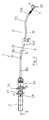
- eine schematische Gesamtansicht eines medizinischen Instrumentes gemäß der Erfindung,
- Fig. 2
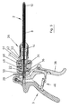
- eine schematische Gesamtansicht eines Instrumentes gemäß einer zweiten Ausführungsform der Erfindung,
- Fig. 3
- das Instrument gemäß
Fig. 2 in teilweise geschnittener An- sicht, - Fig. 4
- eine Detailansicht des distalen Endes des Instrumentes gemäß
Fig. 2 , - Fig. 5
- eine Schnittansicht entlang der Linie V - V in
Fig. 2 , - Fig. 6
- eine Einzelansicht des Maulteiles, des medizinischen In- strumentes gemäß
Figuren 1 ,bis 5 - Fig. 7
- das Instrument gemäß
Fig. 1 , bei welchem der Schaft von der Handhabe getrennt ist, - Fig. 8
- das Instrument gemäß
Figuren 1 und7 mit teilweise ent- nommenen Maulteil, welches als Fasszange ausgebildet ist und - Fig. 9
- ein Instrument entsprechend
Fig. 8 , wobei das Maulteil als Schere ausgebildet ist.
- Fig. 1
- a schematic overall view of a medical instrument according to the invention,
- Fig. 2
- a schematic overall view of an instrument according to a second embodiment of the invention,
- Fig. 3
- the instrument according to
Fig. 2 in a partially sectioned view, - Fig. 4
- a detailed view of the distal end of the instrument according to
Fig. 2 . - Fig. 5
- a sectional view taken along the line V - V in
Fig. 2 . - Fig. 6
- a single view of the jaw part, the medical instrument according to
FIGS. 1 to 5 . - Fig. 7
- the instrument according to
Fig. 1 in which the shaft is separated from the handle, - Fig. 8
- the instrument according to
FIGS. 1 and7 with partially removed jaw part, which is designed as a forceps and - Fig. 9
- an instrument accordingly
Fig. 8 , wherein the jaw part is designed as a pair of scissors.
In beiden Ausführungsformen der Erfindung, d.h. der Ausführungsform gemäß
Dieser Schaft 6 ist aus mehreren Teilen ausgebildet. Direkt an die Handhabe 3 schließt sich in distaler Richtung zunächst ein starres Außenrohr 8 an, welches aus zwei zueinander gewinkelten Abschnitten 8a und 8b gebildet ist, welche über einen Abwinkelbereich 10 fest miteinander verbunden sind. Der Abschnitt 8a und der Abschnitt 8b sowie der Abbiegebereich 10 sind vorzugsweise einteilig oder einstückig ausgebildet. Aufgrund der starren Ausgestaltung des Außenrohres gibt der Abwinkelbereich 10 einen definierten Winkel der Längsachsen der Abschnitte 8a und 8b zueinander vor. Am distalen Ende 12 erstreckt sich aus dem Außenrohr 8 heraus ein äußeres Schaftrohr 14, welches ebenfalls aus zwei Abschnitten 14a und 14b gebildet ist, die über einen starren Abwinkelbereich 16 fest miteinander verbunden sind. Die Abschnitte 14a und 14b sind dabei mit dem Abwinkelbereich 16 einteilig oder einstückig ausgebildet. Aufgrund der starren Ausgestaltung des äußeren Schaftrohres 14 ist durch den definierten Winkel des Abwinkelbereiches 16 ein definierter Winkel zwischen den Längsachsen der Abschnitte 14a und 14b zueinander vorgegeben.This
Insgesamt ist somit der Schaft zweimal gewinkelt, nämlich in dem Abwinkelbereich 10 und dem Abwinkelbereich 16. Der Abschnitt 14a des äußeren Schaftrohres 14 bildet den längsten Abschnitt des Schaftes 6 und ist derjenige Abschnitt, welcher bei der Operation im Inneren eines Zugangstubus gelegen ist. Der Abwinkelbereich 10 ist bei dieser Positionierung proximalseitig des Zugangstubuses gelegen, während der Abwinkelbereich 16 distalseitig des Zugangstubus gelegen ist. Am distalen Ende des Abschnittes 14b des äußeren Schaftrohres 14 ist mit diesem drehfest das Maulteil 4 durch die Gewindehülse 18 des Maulteiles verbunden. Anstelle der Gewindehülse kann auch ein Bajonettverschlussvorgesehen werden. Relativ drehbar zu dieser proximalen Gewindehülse 18 ist ein distaler Abschnitt des Maulteils 4, welcher im Wesentlichen von den beiden zueinander beweglichen Teilen 20 gebildet wird. Bei der Ausführungsform gemäß
Ferner ist das äußere Schaftrohr 14 um die Längsachse des Abschnittes 14a relativ zu dem Außenrohr 10 drehbar. Die Drehung des Maulteiles 4 und des äußeren Schaftrohres 14 erfolgt durch zwei Handräder 22 und 24 in dem Handhabenteil 3. Dabei ist das Handrad 22 für die Drehung des Maulteils 4 und das Handrad 24 für die Drehung des äußeren Schaftrohres 14 vorgesehen. Das bedeutet, wenn das Handrad 22 in Richtung des Pfeils A gedreht wird, dreht sich entsprechend das Maulteil 4 in Richtung des Pfeils A. Wen das Handrad 24 in Richtung des Pfeils B gedreht wird, dreht sich entsprechend das äußere Schaftrohr 14 in Richtung des Pfeils B (
Der Zangeneinsatz 2 ist mit dem Handhabenteil 3 lösbar über eine Kupplung 26 verbunden. Diese Kupplung ist in der Weise ausgestaltet, wie es aus
Das Handhabenteil weist ferner einen HF-Anschluss 28 zur Verbindung mit einer Hochfrequenzspannungsquelle auf.The handle portion further includes an
Die Ausführungsform gemäß
Anhand von
Im Inneren des äußeren Schaftrohres 14 ist ein Innenrohr 34 angeordnet, welches sich vom distalen Ende des Instrumentes 1 bis zu dem Handhabenteil 3 erstreckt. Das Innenrohr 34 ist im Inneren des äußeren Schaftrohres 14 um seine Längsachse drehbar. An seinem proximalen Ende ist das Innenrohr 34 mit dem Handrad 22 verbunden. Am distalen Ende ist das Innenrohr 34 mit dem drehbaren Abschnitt des Maulteiles 4 verbunden. Wenn das Handrad 22 in Richtung des Pfeils A gedreht wird, wird das Innenrohr 34 um seine Längsachse gedreht und überträgt diese Drehbewegung auf das Maulteil 4, sodass dessen distaler Abschnitt mit den beweglichen Teilen 20 in Richtung des Pfeils A gedreht wird. Um die Abwinkelbereiche 10, 16 und 30 entsprechend gewinkelt und dennoch um die Längsachse drehbar durchlaufen zu können, ist das Innenrohr 34 in diesen Bereichen biegbar ausgebildet. Die Ausgestaltung entspricht dabei der biegbaren Ausgestaltung des äußeren Schaftrohres 14 in dem Abwinkelbereich 10. D.h. in den gewinkelten bzw. gekrümmten Abschnitten ist auch das Innenrohr 34 aus einzelnen beweglich miteinander verbundenen Rohrabschnitten 35 gebildet, wie es aus
Wie in
Wie in
Diese Verbindung der Elemente ermöglicht es, dass das Kupplungsteil 26 in Richtung des Pfeils C mit dem Handhabenteil 3 zusammengesteckt werden kann. Wobei die Vielkante 42 und 46 mit den korrespondierenden Aufnahmen 44 und 48 in Eingriff treten. Gleichzeitig wird das proximale Ende der Betätigungsstange 36 über eine Kugelrastverbindung 50 mit dem beweglichen Handhabenteil 38 gekuppelt. Im Übrigen wird die Kupplung 26 mit dem Handhabenteil 3 in der aus
- 1 -1 -
- Instrumentinstrument
- 2 -2 -
- Zangeneinsatztong insert
- 3 -3 -
- HandhabenteilHandle part
- 4 -4 -
- Maulteiljaw
- 6 -6 -
- Schaftshaft
- 8 -8th -
- Außenrohrouter tube
- 10 -10 -
- Abwinkelbereichangled region
- 12 -12 -
- Distales Ende des AußenrohresDistal end of the outer tube
- 14 -14 -
- Äußeres SchaftrohrOuter shaft tube
- 16 -16 -
- Abwinkelbereichangled region
- 18 -18 -
- Gewindehülsethreaded sleeve
- 20 -20 -
- Bewegliche Teile des MaulteilsMoving parts of the jaw part
- 22, 24 -22, 24 -
- Handräderhand wheels
- 26 -26 -
- Kupplungclutch
- 28 -28 -
- HF-AnschlussRF connector
- 30 -30 -
- Abwinkelbereichangled region
- 32 -32 -
- Rohrabschnittpipe section
- 34 -34 -
- Innenrohrinner tube
- 35 -35 -
- Rohrabschnittepipe sections
- 36 -36 -
- Betätigungsstangeactuating rod
- 38 -38 -
- Bewegliches HandhabenteilMobile handle part
- 40 -40 -
- Rastsperredetent
- 42 -42 -
- Vielkantpolyhedron
- 44 -44 -
- Aufnahmeadmission
- 46 -46 -
- Vielkantpolyhedron
- 48 -48 -
- Aufnahmeadmission
- 40 -40 -
- KugelrastverbindungBall locking connection
- 52 -52 -
- Verdrehsicherungtwist
- 53 -53 -
- Ausnehmungrecess
- 54 -54 -
- Kupplungsteilcoupling part
- A, B, C -A, B, C -
- Bewegungsrichtungendirections of movement
Claims (14)
dadurch gekennzeichnet, dass
der Schaft (6) starr ausgebildet ist und zumindest einen proximalen (16) und einen distalen (16)Abwinkelbereich aufweist, in welchen sich die Erstreckungsrichtung des Schaftes (6) ändert,
ein Abschnitt des Schaftes (6), in welchem der distale Abwinkelbereich (16, 30) gelegen ist, relativ zu einem Abschnitt des Schaftes (6), in dem der proximale Abwinkelbereich (10) gelegen ist, um die Längsachse drehbar ist,
und das Maulteil (4) relativ zu dem Schaft (6) um dessen Längsachse am distalen Ende drehbar ist.Medical instrument having a handle (3) arranged at the proximal end, a shaft (6) extending distally from the handle (3) and a movable jaw part (4) arranged at the distal end of the shaft (6),
characterized in that
the shank (6) is rigid and has at least one proximal (16) and one distal (16) angled region into which the extension direction of the shank (6) changes,
a portion of the shaft (6) in which the distal angled portion (16, 30) is located relative to a portion of the shaft (6) in which the proximal angled portion (10) is located, is rotatable about the longitudinal axis,
and the jaw member (4) is rotatable relative to the shaft (6) about its longitudinal axis at the distal end.
Applications Claiming Priority (1)
| Application Number | Priority Date | Filing Date | Title |
|---|---|---|---|
| DE102008015418A DE102008015418A1 (en) | 2008-03-20 | 2008-03-20 | Medical instrument |
Publications (2)
| Publication Number | Publication Date |
|---|---|
| EP2103264A1 true EP2103264A1 (en) | 2009-09-23 |
| EP2103264B1 EP2103264B1 (en) | 2011-12-14 |
Family
ID=40679324
Family Applications (1)
| Application Number | Title | Priority Date | Filing Date |
|---|---|---|---|
| EP09003714A Active EP2103264B1 (en) | 2008-03-20 | 2009-03-14 | Medical instrument |
Country Status (6)
| Country | Link |
|---|---|
| US (1) | US8128650B2 (en) |
| EP (1) | EP2103264B1 (en) |
| JP (1) | JP5193915B2 (en) |
| CN (1) | CN101536921B (en) |
| AT (1) | ATE536818T1 (en) |
| DE (1) | DE102008015418A1 (en) |
Cited By (1)
| Publication number | Priority date | Publication date | Assignee | Title |
|---|---|---|---|---|
| WO2013064487A1 (en) * | 2011-10-31 | 2013-05-10 | Richard Wolf Gmbh | Handle for a medical instrument |
Families Citing this family (19)
| Publication number | Priority date | Publication date | Assignee | Title |
|---|---|---|---|---|
| US20110264136A1 (en) * | 2008-12-12 | 2011-10-27 | Seung Wook Choi | Surgical instrument |
| DE102009017175B4 (en) * | 2009-04-09 | 2011-05-05 | Richard Wolf Gmbh | Method for producing a bendable tube |
| US8398633B2 (en) * | 2009-10-30 | 2013-03-19 | Covidien Lp | Jaw roll joint |
| DE102009051515A1 (en) | 2009-10-31 | 2011-05-05 | Richard Wolf Gmbh | Medical instrument |
| DE102010011926A1 (en) * | 2010-03-18 | 2011-09-22 | Olympus Winter & Ibe Gmbh | Laparoscopic needle holder |
| WO2011163520A2 (en) | 2010-06-25 | 2011-12-29 | Kieturakis Maciej J | Single port laparoscopic access with laterally spaced virtual insertion points |
| CN102858226B (en) * | 2010-09-28 | 2015-02-04 | 奥林巴斯医疗株式会社 | Endoscope device |
| ES2526294T3 (en) * | 2010-10-01 | 2015-01-09 | Microline Surgical, Inc. | Laparoscopy medical device with detachable tip |
| US9308013B2 (en) * | 2010-11-03 | 2016-04-12 | Gyrus Ent, L.L.C. | Surgical tool with sheath |
| KR101259701B1 (en) * | 2011-03-24 | 2013-05-06 | 정창욱 | Instrument for Minimally Invasive Surgery Having Curved Shaft |
| DE102011007119A1 (en) | 2011-04-11 | 2012-10-11 | Karl Storz Gmbh & Co. Kg | Handling device for a micro-invasive-surgical instrument |
| DE102011007121A1 (en) | 2011-04-11 | 2012-10-11 | Karl Storz Gmbh & Co. Kg | Handling device for a micro-invasive-surgical instrument |
| DE102011007122A1 (en) | 2011-04-11 | 2012-10-11 | Karl Storz Gmbh & Co. Kg | Tool for a micro-invasive-surgical instrument |
| US9326785B2 (en) * | 2011-05-12 | 2016-05-03 | Microline Surgical, Inc. | Connector for a laparoscopic surgical system |
| DE102011081464A1 (en) | 2011-08-24 | 2013-02-28 | Karl Storz Gmbh & Co. Kg | Tool for a micro-invasive-surgical instrument |
| US8747238B2 (en) * | 2012-06-28 | 2014-06-10 | Ethicon Endo-Surgery, Inc. | Rotary drive shaft assemblies for surgical instruments with articulatable end effectors |
| CN103908213A (en) * | 2012-12-29 | 2014-07-09 | 上海澳华光电内窥镜有限公司 | Detachable endoscopic device |
| CN109219381A (en) * | 2016-06-13 | 2019-01-15 | 奥林巴斯株式会社 | Medical device |
| EP3760025A1 (en) * | 2019-07-01 | 2021-01-06 | Andreas Stihl AG & Co. KG | Operating device with handle and engine-driven working machine |
Citations (6)
| Publication number | Priority date | Publication date | Assignee | Title |
|---|---|---|---|---|
| GB2284242A (en) * | 1993-11-30 | 1995-05-31 | Wolf Gmbh Richard | Remote movement of manipulator end effector |
| US5620415A (en) * | 1993-01-29 | 1997-04-15 | Smith & Dyonics, Inc. | Surgical instrument |
| EP0764423B1 (en) | 1995-09-22 | 2004-09-29 | Richard Wolf GmbH | Bendable pipe and process of manufacturing |
| DE10357105B3 (en) | 2003-12-06 | 2005-04-07 | Richard Wolf Gmbh | Medical instrument for medical applications comprises an insert and a handle detachedly connected to each other |
| US20050096694A1 (en) * | 2003-10-30 | 2005-05-05 | Woojin Lee | Surgical instrument |
| US20070276430A1 (en) * | 2006-05-23 | 2007-11-29 | Cambridge Endoscopic Devices, Inc. | Surgical instrument |
Family Cites Families (7)
| Publication number | Priority date | Publication date | Assignee | Title |
|---|---|---|---|---|
| US5201743A (en) * | 1992-05-05 | 1993-04-13 | Habley Medical Technology Corp. | Axially extendable endoscopic surgical instrument |
| US20020095175A1 (en) * | 1998-02-24 | 2002-07-18 | Brock David L. | Flexible instrument |
| AU2002224519A1 (en) * | 2000-07-21 | 2002-02-05 | Atropos Limited | A surgical instrument |
| JP4046569B2 (en) * | 2002-07-30 | 2008-02-13 | オリンパス株式会社 | Surgical instrument |
| US7753901B2 (en) * | 2004-07-21 | 2010-07-13 | Tyco Healthcare Group Lp | Laparoscopic instrument and cannula assembly and related surgical method |
| AU2007201204B2 (en) * | 2006-03-23 | 2012-07-12 | Ethicon Endo-Surgery, Inc. | Articulating endoscopic accessory channel |
| US8597280B2 (en) * | 2006-06-13 | 2013-12-03 | Intuitive Surgical Operations, Inc. | Surgical instrument actuator |
-
2008
- 2008-03-20 DE DE102008015418A patent/DE102008015418A1/en not_active Withdrawn
-
2009
- 2009-03-14 AT AT09003714T patent/ATE536818T1/en active
- 2009-03-14 EP EP09003714A patent/EP2103264B1/en active Active
- 2009-03-18 JP JP2009065442A patent/JP5193915B2/en not_active Expired - Fee Related
- 2009-03-19 US US12/407,450 patent/US8128650B2/en not_active Expired - Fee Related
- 2009-03-20 CN CN2009101289592A patent/CN101536921B/en not_active Expired - Fee Related
Patent Citations (6)
| Publication number | Priority date | Publication date | Assignee | Title |
|---|---|---|---|---|
| US5620415A (en) * | 1993-01-29 | 1997-04-15 | Smith & Dyonics, Inc. | Surgical instrument |
| GB2284242A (en) * | 1993-11-30 | 1995-05-31 | Wolf Gmbh Richard | Remote movement of manipulator end effector |
| EP0764423B1 (en) | 1995-09-22 | 2004-09-29 | Richard Wolf GmbH | Bendable pipe and process of manufacturing |
| US20050096694A1 (en) * | 2003-10-30 | 2005-05-05 | Woojin Lee | Surgical instrument |
| DE10357105B3 (en) | 2003-12-06 | 2005-04-07 | Richard Wolf Gmbh | Medical instrument for medical applications comprises an insert and a handle detachedly connected to each other |
| US20070276430A1 (en) * | 2006-05-23 | 2007-11-29 | Cambridge Endoscopic Devices, Inc. | Surgical instrument |
Cited By (3)
| Publication number | Priority date | Publication date | Assignee | Title |
|---|---|---|---|---|
| WO2013064487A1 (en) * | 2011-10-31 | 2013-05-10 | Richard Wolf Gmbh | Handle for a medical instrument |
| CN103917177A (en) * | 2011-10-31 | 2014-07-09 | 理查德·沃尔夫有限公司 | Handle for a medical instrument |
| US9700289B2 (en) | 2011-10-31 | 2017-07-11 | Richard Wolf Gmbh | Handle for a medical instrument |
Also Published As
| Publication number | Publication date |
|---|---|
| ATE536818T1 (en) | 2011-12-15 |
| JP2009226213A (en) | 2009-10-08 |
| JP5193915B2 (en) | 2013-05-08 |
| US20090240274A1 (en) | 2009-09-24 |
| DE102008015418A1 (en) | 2009-09-24 |
| US8128650B2 (en) | 2012-03-06 |
| CN101536921B (en) | 2011-03-23 |
| EP2103264B1 (en) | 2011-12-14 |
| CN101536921A (en) | 2009-09-23 |
Similar Documents
| Publication | Publication Date | Title |
|---|---|---|
| EP2103264B1 (en) | Medical instrument | |
| EP2510887B1 (en) | Tool for a micro-surgical instrument | |
| DE19521257C2 (en) | Surgical forceps | |
| DE102012008970B3 (en) | Surgical tooling | |
| EP2769682B1 (en) | Endoscopic instrument and shaft for an endoscopic instrument | |
| EP2305145A1 (en) | Dismountable medical pincer system | |
| WO2011032712A1 (en) | Medical device | |
| EP1701661B1 (en) | Medical cutting and/or holding instrument | |
| EP1052945A1 (en) | Tubular medical instrument | |
| EP2910202B1 (en) | Instrument for carrying out medical procedures | |
| DE102014117393A1 (en) | Turnable and bendable medical instrument | |
| EP2340759A1 (en) | Endoscopic instrument | |
| EP3100690A1 (en) | Instrument for endoscopic surgery | |
| EP2653118B1 (en) | Micro-invasive medical instrument | |
| EP2653119B1 (en) | Medical instrument and method for assembling a medical instrument | |
| DE202007003093U1 (en) | Surgical instrument for using with a trocar to insert surgical instruments has a shank and a tool element set up to move in bearings on a distal end of the shank | |
| EP3167824B1 (en) | Surgical instrument which can be disassembled | |
| EP2014246A2 (en) | Medical instrument | |
| EP3503820B1 (en) | Surgical jaw-type instrument comprising a counterbalanced lever system | |
| DE10342002A1 (en) | Medical instrument for the preparation of tissue | |
| DE102009037045A1 (en) | Tubular shaft for surgical instrument, particularly morcellator, shaver or reamer, has rigid section and longitudinally extended tubular element, which has opposite longitudinally movable sections | |
| DE102007010304B4 (en) | Surgical instruments | |
| EP3943024B1 (en) | Medical instrument | |
| WO2011079897A1 (en) | Control of a tubular shaft of a surgical instrument | |
| DE102015103913A1 (en) | Hollow shaft instrument and in particular medical endoscopic hollow shaft instrument |
Legal Events
| Date | Code | Title | Description |
|---|---|---|---|
| PUAI | Public reference made under article 153(3) epc to a published international application that has entered the european phase |
Free format text: ORIGINAL CODE: 0009012 |
|
| AK | Designated contracting states |
Kind code of ref document: A1 Designated state(s): AT BE BG CH CY CZ DE DK EE ES FI FR GB GR HR HU IE IS IT LI LT LU LV MC MK MT NL NO PL PT RO SE SI SK TR |
|
| AX | Request for extension of the european patent |
Extension state: AL BA RS |
|
| 17P | Request for examination filed |
Effective date: 20090907 |
|
| AKX | Designation fees paid |
Designated state(s): AT BE BG CH CY CZ DE DK EE ES FI FR GB GR HR HU IE IS IT LI LT LU LV MC MK MT NL NO PL PT RO SE SI SK TR |
|
| GRAP | Despatch of communication of intention to grant a patent |
Free format text: ORIGINAL CODE: EPIDOSNIGR1 |
|
| GRAS | Grant fee paid |
Free format text: ORIGINAL CODE: EPIDOSNIGR3 |
|
| GRAA | (expected) grant |
Free format text: ORIGINAL CODE: 0009210 |
|
| AK | Designated contracting states |
Kind code of ref document: B1 Designated state(s): AT BE BG CH CY CZ DE DK EE ES FI FR GB GR HR HU IE IS IT LI LT LU LV MC MK MT NL NO PL PT RO SE SI SK TR |
|
| REG | Reference to a national code |
Ref country code: GB Ref legal event code: FG4D Free format text: NOT ENGLISH |
|
| REG | Reference to a national code |
Ref country code: CH Ref legal event code: EP |
|
| REG | Reference to a national code |
Ref country code: IE Ref legal event code: FG4D |
|
| REG | Reference to a national code |
Ref country code: DE Ref legal event code: R096 Ref document number: 502009002141 Country of ref document: DE Effective date: 20120209 |
|
| REG | Reference to a national code |
Ref country code: CH Ref legal event code: NV Representative=s name: ISLER & PEDRAZZINI AG |
|
| REG | Reference to a national code |
Ref country code: NL Ref legal event code: T3 |
|
| PG25 | Lapsed in a contracting state [announced via postgrant information from national office to epo] |
Ref country code: NO Free format text: LAPSE BECAUSE OF FAILURE TO SUBMIT A TRANSLATION OF THE DESCRIPTION OR TO PAY THE FEE WITHIN THE PRESCRIBED TIME-LIMIT Effective date: 20120314 Ref country code: LT Free format text: LAPSE BECAUSE OF FAILURE TO SUBMIT A TRANSLATION OF THE DESCRIPTION OR TO PAY THE FEE WITHIN THE PRESCRIBED TIME-LIMIT Effective date: 20111214 |
|
| LTIE | Lt: invalidation of european patent or patent extension |
Effective date: 20111214 |
|
| PG25 | Lapsed in a contracting state [announced via postgrant information from national office to epo] |
Ref country code: GR Free format text: LAPSE BECAUSE OF FAILURE TO SUBMIT A TRANSLATION OF THE DESCRIPTION OR TO PAY THE FEE WITHIN THE PRESCRIBED TIME-LIMIT Effective date: 20120315 Ref country code: HR Free format text: LAPSE BECAUSE OF FAILURE TO SUBMIT A TRANSLATION OF THE DESCRIPTION OR TO PAY THE FEE WITHIN THE PRESCRIBED TIME-LIMIT Effective date: 20111214 Ref country code: SI Free format text: LAPSE BECAUSE OF FAILURE TO SUBMIT A TRANSLATION OF THE DESCRIPTION OR TO PAY THE FEE WITHIN THE PRESCRIBED TIME-LIMIT Effective date: 20111214 Ref country code: SE Free format text: LAPSE BECAUSE OF FAILURE TO SUBMIT A TRANSLATION OF THE DESCRIPTION OR TO PAY THE FEE WITHIN THE PRESCRIBED TIME-LIMIT Effective date: 20111214 Ref country code: LV Free format text: LAPSE BECAUSE OF FAILURE TO SUBMIT A TRANSLATION OF THE DESCRIPTION OR TO PAY THE FEE WITHIN THE PRESCRIBED TIME-LIMIT Effective date: 20111214 |
|
| PG25 | Lapsed in a contracting state [announced via postgrant information from national office to epo] |
Ref country code: CY Free format text: LAPSE BECAUSE OF FAILURE TO SUBMIT A TRANSLATION OF THE DESCRIPTION OR TO PAY THE FEE WITHIN THE PRESCRIBED TIME-LIMIT Effective date: 20111214 |
|
| REG | Reference to a national code |
Ref country code: IE Ref legal event code: FD4D |
|
| PG25 | Lapsed in a contracting state [announced via postgrant information from national office to epo] |
Ref country code: CZ Free format text: LAPSE BECAUSE OF FAILURE TO SUBMIT A TRANSLATION OF THE DESCRIPTION OR TO PAY THE FEE WITHIN THE PRESCRIBED TIME-LIMIT Effective date: 20111214 Ref country code: IS Free format text: LAPSE BECAUSE OF FAILURE TO SUBMIT A TRANSLATION OF THE DESCRIPTION OR TO PAY THE FEE WITHIN THE PRESCRIBED TIME-LIMIT Effective date: 20120414 Ref country code: EE Free format text: LAPSE BECAUSE OF FAILURE TO SUBMIT A TRANSLATION OF THE DESCRIPTION OR TO PAY THE FEE WITHIN THE PRESCRIBED TIME-LIMIT Effective date: 20111214 Ref country code: IE Free format text: LAPSE BECAUSE OF FAILURE TO SUBMIT A TRANSLATION OF THE DESCRIPTION OR TO PAY THE FEE WITHIN THE PRESCRIBED TIME-LIMIT Effective date: 20111214 Ref country code: SK Free format text: LAPSE BECAUSE OF FAILURE TO SUBMIT A TRANSLATION OF THE DESCRIPTION OR TO PAY THE FEE WITHIN THE PRESCRIBED TIME-LIMIT Effective date: 20111214 Ref country code: BG Free format text: LAPSE BECAUSE OF FAILURE TO SUBMIT A TRANSLATION OF THE DESCRIPTION OR TO PAY THE FEE WITHIN THE PRESCRIBED TIME-LIMIT Effective date: 20120314 |
|
| PG25 | Lapsed in a contracting state [announced via postgrant information from national office to epo] |
Ref country code: RO Free format text: LAPSE BECAUSE OF FAILURE TO SUBMIT A TRANSLATION OF THE DESCRIPTION OR TO PAY THE FEE WITHIN THE PRESCRIBED TIME-LIMIT Effective date: 20111214 Ref country code: PT Free format text: LAPSE BECAUSE OF FAILURE TO SUBMIT A TRANSLATION OF THE DESCRIPTION OR TO PAY THE FEE WITHIN THE PRESCRIBED TIME-LIMIT Effective date: 20120416 Ref country code: PL Free format text: LAPSE BECAUSE OF FAILURE TO SUBMIT A TRANSLATION OF THE DESCRIPTION OR TO PAY THE FEE WITHIN THE PRESCRIBED TIME-LIMIT Effective date: 20111214 |
|
| PLBE | No opposition filed within time limit |
Free format text: ORIGINAL CODE: 0009261 |
|
| STAA | Information on the status of an ep patent application or granted ep patent |
Free format text: STATUS: NO OPPOSITION FILED WITHIN TIME LIMIT |
|
| PG25 | Lapsed in a contracting state [announced via postgrant information from national office to epo] |
Ref country code: DK Free format text: LAPSE BECAUSE OF FAILURE TO SUBMIT A TRANSLATION OF THE DESCRIPTION OR TO PAY THE FEE WITHIN THE PRESCRIBED TIME-LIMIT Effective date: 20111214 Ref country code: MC Free format text: LAPSE BECAUSE OF NON-PAYMENT OF DUE FEES Effective date: 20120331 |
|
| 26N | No opposition filed |
Effective date: 20120917 |
|
| REG | Reference to a national code |
Ref country code: DE Ref legal event code: R097 Ref document number: 502009002141 Country of ref document: DE Effective date: 20120917 |
|
| PG25 | Lapsed in a contracting state [announced via postgrant information from national office to epo] |
Ref country code: MK Free format text: LAPSE BECAUSE OF FAILURE TO SUBMIT A TRANSLATION OF THE DESCRIPTION OR TO PAY THE FEE WITHIN THE PRESCRIBED TIME-LIMIT Effective date: 20111214 |
|
| PG25 | Lapsed in a contracting state [announced via postgrant information from national office to epo] |
Ref country code: ES Free format text: LAPSE BECAUSE OF FAILURE TO SUBMIT A TRANSLATION OF THE DESCRIPTION OR TO PAY THE FEE WITHIN THE PRESCRIBED TIME-LIMIT Effective date: 20120325 |
|
| PG25 | Lapsed in a contracting state [announced via postgrant information from national office to epo] |
Ref country code: FI Free format text: LAPSE BECAUSE OF FAILURE TO SUBMIT A TRANSLATION OF THE DESCRIPTION OR TO PAY THE FEE WITHIN THE PRESCRIBED TIME-LIMIT Effective date: 20111214 |
|
| PG25 | Lapsed in a contracting state [announced via postgrant information from national office to epo] |
Ref country code: MT Free format text: LAPSE BECAUSE OF FAILURE TO SUBMIT A TRANSLATION OF THE DESCRIPTION OR TO PAY THE FEE WITHIN THE PRESCRIBED TIME-LIMIT Effective date: 20111214 |
|
| PGFP | Annual fee paid to national office [announced via postgrant information from national office to epo] |
Ref country code: LU Payment date: 20140117 Year of fee payment: 6 |
|
| PG25 | Lapsed in a contracting state [announced via postgrant information from national office to epo] |
Ref country code: TR Free format text: LAPSE BECAUSE OF FAILURE TO SUBMIT A TRANSLATION OF THE DESCRIPTION OR TO PAY THE FEE WITHIN THE PRESCRIBED TIME-LIMIT Effective date: 20111214 |
|
| PGFP | Annual fee paid to national office [announced via postgrant information from national office to epo] |
Ref country code: BE Payment date: 20140131 Year of fee payment: 6 Ref country code: CH Payment date: 20140310 Year of fee payment: 6 Ref country code: NL Payment date: 20140317 Year of fee payment: 6 |
|
| PGFP | Annual fee paid to national office [announced via postgrant information from national office to epo] |
Ref country code: IT Payment date: 20140121 Year of fee payment: 6 Ref country code: FR Payment date: 20140114 Year of fee payment: 6 Ref country code: AT Payment date: 20140327 Year of fee payment: 6 |
|
| PGFP | Annual fee paid to national office [announced via postgrant information from national office to epo] |
Ref country code: GB Payment date: 20140226 Year of fee payment: 6 |
|
| PG25 | Lapsed in a contracting state [announced via postgrant information from national office to epo] |
Ref country code: HU Free format text: LAPSE BECAUSE OF FAILURE TO SUBMIT A TRANSLATION OF THE DESCRIPTION OR TO PAY THE FEE WITHIN THE PRESCRIBED TIME-LIMIT Effective date: 20090314 |
|
| PG25 | Lapsed in a contracting state [announced via postgrant information from national office to epo] |
Ref country code: LU Free format text: LAPSE BECAUSE OF NON-PAYMENT OF DUE FEES Effective date: 20150314 |
|
| REG | Reference to a national code |
Ref country code: CH Ref legal event code: PL |
|
| REG | Reference to a national code |
Ref country code: AT Ref legal event code: MM01 Ref document number: 536818 Country of ref document: AT Kind code of ref document: T Effective date: 20150314 |
|
| GBPC | Gb: european patent ceased through non-payment of renewal fee |
Effective date: 20150314 |
|
| REG | Reference to a national code |
Ref country code: NL Ref legal event code: MM Effective date: 20150401 |
|
| PG25 | Lapsed in a contracting state [announced via postgrant information from national office to epo] |
Ref country code: IT Free format text: LAPSE BECAUSE OF NON-PAYMENT OF DUE FEES Effective date: 20150314 |
|
| REG | Reference to a national code |
Ref country code: FR Ref legal event code: ST Effective date: 20151130 |
|
| PG25 | Lapsed in a contracting state [announced via postgrant information from national office to epo] |
Ref country code: CH Free format text: LAPSE BECAUSE OF NON-PAYMENT OF DUE FEES Effective date: 20150331 Ref country code: GB Free format text: LAPSE BECAUSE OF NON-PAYMENT OF DUE FEES Effective date: 20150314 Ref country code: LI Free format text: LAPSE BECAUSE OF NON-PAYMENT OF DUE FEES Effective date: 20150331 |
|
| PG25 | Lapsed in a contracting state [announced via postgrant information from national office to epo] |
Ref country code: AT Free format text: LAPSE BECAUSE OF NON-PAYMENT OF DUE FEES Effective date: 20150314 Ref country code: FR Free format text: LAPSE BECAUSE OF NON-PAYMENT OF DUE FEES Effective date: 20150331 |
|
| PG25 | Lapsed in a contracting state [announced via postgrant information from national office to epo] |
Ref country code: NL Free format text: LAPSE BECAUSE OF NON-PAYMENT OF DUE FEES Effective date: 20150401 |
|
| PG25 | Lapsed in a contracting state [announced via postgrant information from national office to epo] |
Ref country code: BE Free format text: LAPSE BECAUSE OF NON-PAYMENT OF DUE FEES Effective date: 20150331 |
|
| REG | Reference to a national code |
Ref country code: DE Ref legal event code: R084 Ref document number: 502009002141 Country of ref document: DE |
|
| PGFP | Annual fee paid to national office [announced via postgrant information from national office to epo] |
Ref country code: DE Payment date: 20230320 Year of fee payment: 15 |