EP2085848A1 - Processing device and processing method for processing objects through time measurement - Google Patents
Processing device and processing method for processing objects through time measurement Download PDFInfo
- Publication number
- EP2085848A1 EP2085848A1 EP08001825A EP08001825A EP2085848A1 EP 2085848 A1 EP2085848 A1 EP 2085848A1 EP 08001825 A EP08001825 A EP 08001825A EP 08001825 A EP08001825 A EP 08001825A EP 2085848 A1 EP2085848 A1 EP 2085848A1
- Authority
- EP
- European Patent Office
- Prior art keywords
- time
- machine
- control unit
- processing
- unit
- Prior art date
- Legal status (The legal status is an assumption and is not a legal conclusion. Google has not performed a legal analysis and makes no representation as to the accuracy of the status listed.)
- Granted
Links
Images

Classifications
-
- G—PHYSICS
- G05—CONTROLLING; REGULATING
- G05B—CONTROL OR REGULATING SYSTEMS IN GENERAL; FUNCTIONAL ELEMENTS OF SUCH SYSTEMS; MONITORING OR TESTING ARRANGEMENTS FOR SUCH SYSTEMS OR ELEMENTS
- G05B19/00—Programme-control systems
- G05B19/02—Programme-control systems electric
- G05B19/418—Total factory control, i.e. centrally controlling a plurality of machines, e.g. direct or distributed numerical control [DNC], flexible manufacturing systems [FMS], integrated manufacturing systems [IMS], computer integrated manufacturing [CIM]
- G05B19/41815—Total factory control, i.e. centrally controlling a plurality of machines, e.g. direct or distributed numerical control [DNC], flexible manufacturing systems [FMS], integrated manufacturing systems [IMS], computer integrated manufacturing [CIM] characterised by the cooperation between machine tools, manipulators and conveyor or other workpiece supply system, workcell
-
- G—PHYSICS
- G05—CONTROLLING; REGULATING
- G05B—CONTROL OR REGULATING SYSTEMS IN GENERAL; FUNCTIONAL ELEMENTS OF SUCH SYSTEMS; MONITORING OR TESTING ARRANGEMENTS FOR SUCH SYSTEMS OR ELEMENTS
- G05B19/00—Programme-control systems
- G05B19/02—Programme-control systems electric
- G05B19/04—Programme control other than numerical control, i.e. in sequence controllers or logic controllers
- G05B19/042—Programme control other than numerical control, i.e. in sequence controllers or logic controllers using digital processors
- G05B19/0421—Multiprocessor system
-
- G—PHYSICS
- G05—CONTROLLING; REGULATING
- G05B—CONTROL OR REGULATING SYSTEMS IN GENERAL; FUNCTIONAL ELEMENTS OF SUCH SYSTEMS; MONITORING OR TESTING ARRANGEMENTS FOR SUCH SYSTEMS OR ELEMENTS
- G05B2219/00—Program-control systems
- G05B2219/20—Pc systems
- G05B2219/25—Pc structure of the system
- G05B2219/25049—Master processor gives timing information to slaves
-
- G—PHYSICS
- G05—CONTROLLING; REGULATING
- G05B—CONTROL OR REGULATING SYSTEMS IN GENERAL; FUNCTIONAL ELEMENTS OF SUCH SYSTEMS; MONITORING OR TESTING ARRANGEMENTS FOR SUCH SYSTEMS OR ELEMENTS
- G05B2219/00—Program-control systems
- G05B2219/30—Nc systems
- G05B2219/33—Director till display
- G05B2219/33097—Variable ticks, align clocks, to synchronise cycles with other machine, robot
-
- G—PHYSICS
- G05—CONTROLLING; REGULATING
- G05B—CONTROL OR REGULATING SYSTEMS IN GENERAL; FUNCTIONAL ELEMENTS OF SUCH SYSTEMS; MONITORING OR TESTING ARRANGEMENTS FOR SUCH SYSTEMS OR ELEMENTS
- G05B2219/00—Program-control systems
- G05B2219/30—Nc systems
- G05B2219/34—Director, elements to supervisory
- G05B2219/34413—Add time stamp to command message
-
- G—PHYSICS
- G05—CONTROLLING; REGULATING
- G05B—CONTROL OR REGULATING SYSTEMS IN GENERAL; FUNCTIONAL ELEMENTS OF SUCH SYSTEMS; MONITORING OR TESTING ARRANGEMENTS FOR SUCH SYSTEMS OR ELEMENTS
- G05B2219/00—Program-control systems
- G05B2219/30—Nc systems
- G05B2219/45—Nc applications
- G05B2219/45051—Transfer line
-
- G—PHYSICS
- G05—CONTROLLING; REGULATING
- G05B—CONTROL OR REGULATING SYSTEMS IN GENERAL; FUNCTIONAL ELEMENTS OF SUCH SYSTEMS; MONITORING OR TESTING ARRANGEMENTS FOR SUCH SYSTEMS OR ELEMENTS
- G05B2219/00—Program-control systems
- G05B2219/30—Nc systems
- G05B2219/45—Nc applications
- G05B2219/45229—Woodworking
-
- G—PHYSICS
- G05—CONTROLLING; REGULATING
- G05B—CONTROL OR REGULATING SYSTEMS IN GENERAL; FUNCTIONAL ELEMENTS OF SUCH SYSTEMS; MONITORING OR TESTING ARRANGEMENTS FOR SUCH SYSTEMS OR ELEMENTS
- G05B2219/00—Program-control systems
- G05B2219/30—Nc systems
- G05B2219/45—Nc applications
- G05B2219/45234—Thin flat workpiece, sheet metal machining
-
- Y—GENERAL TAGGING OF NEW TECHNOLOGICAL DEVELOPMENTS; GENERAL TAGGING OF CROSS-SECTIONAL TECHNOLOGIES SPANNING OVER SEVERAL SECTIONS OF THE IPC; TECHNICAL SUBJECTS COVERED BY FORMER USPC CROSS-REFERENCE ART COLLECTIONS [XRACs] AND DIGESTS
- Y02—TECHNOLOGIES OR APPLICATIONS FOR MITIGATION OR ADAPTATION AGAINST CLIMATE CHANGE
- Y02P—CLIMATE CHANGE MITIGATION TECHNOLOGIES IN THE PRODUCTION OR PROCESSING OF GOODS
- Y02P90/00—Enabling technologies with a potential contribution to greenhouse gas [GHG] emissions mitigation
- Y02P90/02—Total factory control, e.g. smart factories, flexible manufacturing systems [FMS] or integrated manufacturing systems [IMS]
Definitions
- the present invention relates to a processing device and a processing method for processing moving objects, and more particularly to a processing device and a processing method for continuous measurement and processing of moving objects in a continuous machine by means of travel / time measurement in distributed systems.
- workpieces such as rigid plate material, such as solid wood or chipboard, so-called blockboard, plywood, composite panels made of wood, plastic or metal or the like detected on a conveyor and then performed a processing on the same.
- rigid plate material such as solid wood or chipboard, so-called blockboard, plywood, composite panels made of wood, plastic or metal or the like
- machining operation on the objects can be carried out in such a continuous machining, but various machining operations are possible, such as cutting, milling, grinding, drilling, etc. Further, it is also possible other parts on the objects, such as Workpieces, apply or stick or unscrew.
- the workpiece in an automated sequence of workpiece machining, can be guided to a plurality of processing stations by means of a conveyor with belt or chain conveyor without people having to intervene in the workflow.
- pass-through machines are equipped with a workpiece detection system and a position measuring system whose signals are fed to a control unit for processing.
- a workpiece In the inlet region of the conveyor, a workpiece can be detected, and a corresponding signal can be output.
- the approximate speed of the conveyor belt or transport chain e.g. can be determined by measuring the distance traveled at different times, thereby the approximate position of the workpiece in the continuous machine can be determined.
- a sensor By positioning sensors on the conveyor can thus be issued a signal that indicates that the arrival of a workpiece or object is measured at a sensor, which corresponds to the position of the workpiece. Then, a downstream actuator can be commanded to switch or move, so that after a certain distance covered the workpiece by the sensor this is processed by the actuator.
- a sensor therefore signals, eg by a trigger signal, that it has measured and an actuator is commanded, eg by a trigger signal, that it should switch or move.
- Disturbing influences are, for example, the reaction of the control, the slippage during feed of the workpiece, tolerances in the feed transport and in the workpiece detection, which can only be detected within certain precision limits.
- the processing device comprises a control unit with a timer for outputting a system time and at least two machine units connected to the control unit configured to receive the system time
- the first machine unit comprises at least one sensor element and is designed for Detecting an event and outputting an event time based on the system time related to the detection of the event
- the second machine unit comprises at least one actuator element, and configured to perform an operation according to a machining time predetermined by the control unit based on System time and event time.
- an exact position of an object in time can be accurately detected and communicated to other machine units via at least one control.
- This allows a much more accurate detection of an object and a significant more accurate control of machine units with actuator elements for processing objects, and saved by simply working in the time domain signal transformations.
- the precision in such a system does not depend on the running time of the communication lines and field buses between the components or the cycle time of the control, but only on the resolution of the system time, that is, the synchronization accuracy of the machine units with each other.
- a processing device in the sense of the invention is any system that has distributed times, and where the time of occurrence of an event, such as the detection of an object, can be sent from one unit to another, and then processed as a processing time after an event time can indicate the execution of an operation.
- the processing device is particularly suitable for a pass-through machine, but does not necessarily have to be a part of a pass-through machine, since cases are conceivable in which a first object is detected, but a Operation is performed on a second object, which need not be together with the first object on a conveyor.
- the first machine unit is designed to output the event with the system time based on the event time as a detection signal to the control unit.
- the control unit of the processing device is informed of the event time based on the system time and may instruct other machine units with the same system time to perform an operation.
- the control unit calculates the processing time based on the event time, wherein preferably the calculated processing time is output as a processing signal to the second machine unit. Therefore, a control unit does not have to output an accurate trigger signal to the second machine unit at a certain processing time, but it is sufficient to calculate a processing time before the processing time and inform the second machine unit beforehand so that the second machine unit itself starts operating at the predetermined time , This allows a more accurate control of the actuator element of the second machine unit.
- the processing device comprises a third machine unit with a second sensor element and a fourth machine unit with a second actuator element, wherein the third and fourth machine units are designed to receive the system time from the control unit, and the control unit is designed based on the Event and the event time to select the machine unit with actuator element to which the processing time is to be notified. Since the machine units with actuator element inform only about the processing time and are not triggered by the control unit at the time of processing, the processing time may be sent at an arbitrary time prior to the processing time so that bottlenecks do not arise on a communication line or field bus, and an accurate drive is ensured in the machine units due to the same time.
- the first and second machine units form a processing unit, which preferably comprises an aggregate control unit.
- the signal processing between the control unit and the unit control unit can be divided, whereby the control unit is relieved.
- the aggregate control unit is designed to communicate with the control unit via a bus system and to receive the system time via the bus system.
- the system time can be output from the control unit to an aggregate control unit, which also supplies the machine units connected thereto with the system time, so that without further communication lines to the control unit, the processing means can be extended by further machine units on the unit control unit.
- control unit synchronizes the machine units.
- a system time must be issued only once by a control unit, since this time can be synchronized in the individual machine units by a simple synchronization signal at later times.
- the first machine unit comprises a first memory for storing events and event times.
- a detected event and / or event time does not have to be immediately addressed to a Control unit can be passed, but can be cached in the machine unit, so that two or more events and / or event times can be sent together to a control unit.
- the second machine unit comprises a second memory for storing processing times.
- the system time corresponds to the real world time.
- real-world time it is possible to ensure that even two machine units far apart from each other, each receiving the world time, have the same time, one event time can be output to a larger network, and one processing time from a larger network, such as Internet, received and can be transferred.
- the processing device is contained in a continuous machine.
- the advantages described above can also be achieved in a continuous machine.
- the pass-through machine comprises an object sensor for detecting an object on a conveyor and for outputting an object detection signal including an object detection time based on the system time.
- an object sensor for detecting an object on a conveyor and for outputting an object detection signal including an object detection time based on the system time.
- the pass-through machine comprises a position sensor for outputting a measurement signal corresponding to a measurement of a position of a conveyor to the control unit, the measurement signal containing a measurement time based on the system time related to the measurement, and wherein the control unit is preferred is configured to calculate a position of an object on the conveyor at different times by using the measurement signal and the detection signal or the object detection signal.
- the control unit is preferred is configured to calculate a position of an object on the conveyor at different times by using the measurement signal and the detection signal or the object detection signal.
- a processing method includes outputting a defined system time from a controller having timers on at least two machine units, detecting an event with the first machine unit, outputting an event time based on the system time related to the detection of the event from the first machine unit to the control unit, and performing an operation according to a processing time predetermined by the control unit, based on the system time and the event time by the second machine unit.
- the method is suitable to be carried out in a continuous machine.
- a simple and reliable method for a precise position determination for objects in a continuous machine can be realized.
- a second machine unit may be designated to receive a command with a timing following the detection of the event to then perform any operation.
- the operation does not necessarily have to be performed on an object that triggered the event at the first machine unit. It is also conceivable that the triggering of this event is another object.
- a first object may trigger an event at an accurately detectable time, the event time, whereby the second machine unit receives a processing time to operate on, for example, a second machine unit.
- the time difference between the event time and the processing time only has to be chosen so large that a communication of the command for performing the operation can arrive at the second machine unit in time before the second machine unit is to perform an operation.
- the processing device may, but does not necessarily have to, be part of a conventional pass-through machine, since it is also suitable for other systems in which a first object is detected but an operation is performed on a second object that is not associated with the first object must lie on a conveyor.
- a pass-through machine may include a pass-through machine for processing plate-shaped workpieces, such as e.g. Solid wood or chipboard, so-called Tischlerplatten, plywood panels, composite panels of wood, plastic or metal or the like.
- a processing device for the pass-through machine comprises a control unit with a timer which generates a system time which is output on at least two machine units.
- the first and second machine units have the same system time, and the detection of an object from the first machine unit can be accurately defined by an event time based on the system time.
- the pass-through machine which transports objects at a constant speed, it can thus be deduced from the location of the first machine unit and the event time when the same object is located at the second machine unit.
- This time referred to below as the processing time, is calculated by the control unit, for example, and sent to the second machine unit so that it can process the object at the defined processing time.
- a position of the object can be accurately detected and transmitted without a control unit having to process trigger signals indicating that a sensor has just been measured, or an actuator should now shift or move.
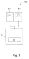
- Fig. 1 schematically shows a processing device 100.
- the processing device 100 includes a control unit C with a timer ZG, a first machine unit S11 with a sensor element SE11 and a second machine unit A11 with an actuator element AE11.
- control unit may be integrated in one of the machine units.
- Fig. 1 The machine units S11 and A11 are connected to the control unit C.
- the connection preferably takes place via a bus system, for example a field bus, wherein Profinet a standard for industrial Ethernet or a modification thereof can be used for the execution of the invention, for example.
- a wireless connection between the machine units and the control unit C is possible.
- the control unit C includes the timer ZG for outputting a system time.
- the control unit C is used to control the processing device 100 and can, for example, specify a processing time based on the system time given by the timer.
- the control unit C can be realized by a processor, computer or integrated circuit, such as an application specific integrated circuit (ASIC) or by software or an appropriate combination of the above.
- ASIC application specific integrated circuit
- the first machine unit S11 includes at least one sensor element SE11 and is configured to detect an event and output an event time based on the system time related to the detection of the event.
- the first machine unit is a sensor.
- the event may involve the detection of a leading edge or trailing edge of an object, for example a wooden panel.
- the first machine unit may store the event time, which is a time at the prevailing system time, and outputs an event time.
- the output event time does not have to be the event time itself, as it is also easy to output time or clock difference from a reference clock or reference time be measured. For example, a value of 5 clocks or 5 seconds after, for example, a last synchronization may be output, with the synchronization occurring at all units at the same time.
- the event may be output to the control unit C as the detection signal based on the system time-based event time.
- the detection signal then contains information about the event, where a simple indication such as yes / no is sufficient, that is, edge detected or not, and the event time, which as stated above, can be given either as an absolute time or as a difference time to a reference time , such as a synchronization process.
- the sensor element SE11 in the first machine unit S11 may be a commercially available sensor element that is used in sensors in automation technology.
- an optical sensor element having a clocking of, for example, 5 kHz may be used, which is a limiting factor for the accuracy of the measurement.
- the second machine unit A11 comprises at least one actuator element AE11 and is designed to perform an operation according to a processing time predetermined by the control unit, based on the system time and the event time.
- the second machine unit A11 is an actuator, ie the converter-related counterpart to a sensor which performs an operation at a predetermined processing time.
- the operation may be, for example, machining in the sense of punching, punching, cutting, gluing, drilling, etc., but other operations, such as redirecting, dispensing or removing an object that is present at the processing time at the second machine unit, are also possible.
- the actuator element may be, for example, an element that can perform such and similar functions.
- the second machine unit A11 receives the processing time based on the system time and the event time, and compares the predetermined processing time with an actual time, the system time prevailing upon receiving the processing time, which is the same for all units in the processing apparatus 100 and waits until the specified processing time corresponds to the system time. Therefore, the processing time may also be an absolute time or a relative time, that is, a time difference measured by a reference time, as described with respect to the event time described above.
- control unit C is designed to calculate the processing time based on the event time.
- the control unit C includes a processor, computer or integrated circuit as described above, and may determine when an object detected at the first machine unit S11, for example, in a conveyorized conveyor machine using the conveyor speed the second machine unit arrives. This arrival time then corresponds to the processing time, namely the time at which an object can be processed by the second machine unit.
- the control unit C is designed to output the processing time as a processing signal to the second machine unit A11.
- the second machine unit When the processing time is reached, the second machine unit then executes one of the operations described above.
- the first machine unit S11 does not report that it has measured, as is conventionally the case, but when or what has measured when, and gives the exact time the measurement, which is understood by all units in the processing device, since all are on the same system time.
- the second machine unit A11 is not informed that it should now shift or move, but is informed when it should go where by the predetermined processing time, based on the system time, which is the same for all units of the processing device 100.
- control unit C can be designed to synchronize.
- the first machine unit S11 may include a first memory, not shown, for storing the events and event times. This can be advantageous in particular in the event that short objects with short distances between leading and trailing edges or short distances between two objects can be detected and buffered, so that not every recorded event or event time must be output immediately, but can be temporarily stored and then multiple events and / or their event times can be issued at once.
- the time until transmission of the event time to the control unit C plus a processing time in the control unit and a time for sending the calculated processing time to the second machine unit A11 is shorter than the time it takes the object to from the first machine unit S11 to the second machine unit A11, for example on a conveyor.
- the second machine unit A11 may also include a second memory, not shown, for storing processing times.
- a second memory not shown, for storing processing times.
- several processing times and / or their processing setpoints can be cached, which can then be processed as needed.
- three processing times and their setpoint values can be stored, so that when the system time reaches one of the processing times, an operation corresponding to the desired value is performed.
- the system time can be the real world time, which means that all units in the processing device 100 can be synchronized, for example, by a radio signal from an atomic clock, such as the atomic clock of the Physikalisch-Technische Bundesweg.
- the first and second machine units may constitute a processing unit. This means that only one bidirectional communication line between the processing unit and the control unit C would then be necessary.
- the processing unit may comprise an aggregate control unit, which will be described later with reference to FIG Fig. 3 will be described in more detail.
- FIG. 2 a flow chart is described, showing the steps of a processing method for example, a continuous machine according to another embodiment of the invention.
- This method can be used, for example, by the in Fig. 1 shown processing apparatus 100 are executed.
- a defined system time from a control unit C with timer ZG to at least two Machine units S11 and A11 output.
- the system time may be the real world time, always paying attention that the units of the system, namely the control unit and machine units, display the same time.
- the system time can be transmitted over a fixed communication line, such as a fieldbus, or wirelessly.
- an event is detected with the first machine unit S11. For example, as described above, an object located on a conveyor of a pass-through machine can be detected if, for example, its leading edge is detected.
- the time related to the detection of the event may be output as the event time based on the system time from the first machine unit S11 to the control unit C.
- This is not a simple trigger signal indicating that, for example, the leading edge of an object has been detected, but a signal indicating the exact time at which the leading edge was detected.
- control unit need not consider a transmission time in a communication line from the first machine unit to the control unit, such as the trigger signal, since the transmitted event time does not change despite possible delays through a communication line. It only needs to be ensured that the time that the event time to the control unit takes and from the control unit to the second machine unit is less than the time that the object needs from the first machine unit to the second machine unit.
- an operation according to a processing time given by the control unit C is based on the system time and the event time, performed by the second machine unit.
- the processing time based on the event time and the system time, is preferably calculated by the control unit.
- the processing time is output, for example, as a processing signal from the control unit C to the second machine unit.
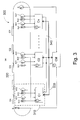
- pass machine 300 comprises a plurality of control units C1 to Cn, a plurality of machine units S11, S21 to Sn1; A11, A21 to An1; S12, S22 to Sn2; A12, A22 to An2, a main control unit CM, an object sensor S, a position sensor G, a conveyor 320, and a bus system 330, 340.
- Fig. 3 is the in Fig. 1 described processing device 100 represented by the machine units S11, A11 and the control unit C1, which in Fig. 3 is referred to as an aggregate control unit for distinguishing from the main control unit CM.
- Fig. 3 Functions of the control unit off Fig. 1 also taken over by the main control unit CM.
- the first and second machine units can also be understood as a processing unit 310, which preferably comprises the unit control unit C1.
- This aggregate control unit C1 and the main control unit CM can perform the functions of in Fig. 1 comply described control unit C.
- sensors and the machine units with actuator element can represent actuators, wherein the sensors and actuators are designed to measure, transmit or receive a time that can be processed directly in the sensors or actuators.
- the processing device may also include a third machine unit S12 with a second sensor element and a fourth machine unit with a second actuator element A12.
- the third and fourth machine units are also designed to receive the system time from the control unit or the main control unit CM by the aggregate control unit C1.
- the aggregate control unit C1 is further configured to select, based on the event and the event time, the engine unit with actuator element A11, A12 to be notified of the machining time.
- a sensor for example, machine unit S11
- an actuator for example, machine unit A11
- an event detected by machine unit S11 is notified to machine unit A11.
- the event is a detection of a leading edge of an object
- that information may be important to the second and fourth machine units, with the second machine unit, for example, drilling a hole in the object and drilling the hole in the fourth machine unit an adhesive is filled.
- the unit control units C1 to Cn shown are preferably designed to communicate with the main control unit CM via a bus system 330, 340 and to receive the system time via the bus system 330, 340.
- a system time is transmitted and preferably also a synchronization takes place via the communication line 340, which is also indicated by the arrow direction.
- a system time represented by the clock in the main control unit is transmitted to the unit control units C1 to Cn.
- a lightning bolt symbol illustrating that a synchronization process can synchronize the aggregate controllers C1 to Cn in phase synchronization.
- the second communication line 330 is bidirectional and sends signals from the unit control units C1 to Cn to the main control unit CM and from the main control unit to the unit control units. For example, the detection signals from the unit control units are sent to the main control unit, and the main control unit CM can send processing signals to the unit control units C1 to Cn.
- the two functions of the communication lines 330 and 340 may also be integrated into a single bus system.
- This can also be relative slow field buses and different control units are used, as described above, in the present invention does not depend on the exact reception or transmission of trigger signals, but signals are sent with a timing and received from / to the machine units. The exact position can thus be detected in time and transmitted over several field buses and different control units.
- the distributed system For example, at a location of the distributed system, e.g. in one of the aggregate control units or the main control unit for data from the position sensor G, the calculated data on the determination of the relative or absolute times and the corresponding paths, the processing times and Aktorsolllitis determined and sent again to different control units and / or the fieldbuses connected actuators.
- processing unit 310 will be described as an example of the unit control units C1 to Cn with their respective machine units.
- the machine units are connected to the control unit C, the aggregate control units C1 to Cn in Fig. 3 , and can communicate bidirectionally with each other.
- the system time is sent to all subordinate aggregate control units C1 to Cn and from there to the connected machine units.
- the processing unit 310 is therefore always kept at the same system time with the other units of the pass-through machine 300.
- the processing unit may include a plurality of machine units that may represent sensors and actuators.
- the continuous machine of Fig. 3 an object sensor S for detecting an object O1 to On on the conveyor 320 and for outputting an object detection signal including an object detection time based on the system time.
- This object detection time is communicated to the main control unit CM.
- the object sensor S functions similarly to the sensor element machine units described above, and thus can prepare the machine units and their aggregate control units for the arrival of an object.
- the objects O1 to On are moved by the conveyor as constant as possible.
- the speed may be in the range of 0.1 m / s to 20 m / s and preferably between 0.5 m / s and 3 m / s.
- the object sensor S registers in each case the positive and / or negative switching edge of an object and links this in the object sensor with the object detection time, similar to the machine units with sensor element.
- the pass-through machine may further include a position encoder G for outputting a measurement signal corresponding to a measurement of a position of the conveyor 320 to the main control unit CM, the measurement signal including a measurement time based on the system time related to the measurement.
- the position sensor G serves to measure the movement of the conveyor 320.
- the position sensor G can measure the progress or rotation of the conveyor 320 at several consecutive times, whereby the distance covered can be measured in a certain time.
- the position of the conveyor belt of the conveyor 320 is preferably determined cyclically in the shortest possible sampling times by the position sensor G and linked in conjunction with the time of measurement.
- This information of the object sensor S and the position sensor G can then be sent to the main control unit CM, where this information can be processed, for example, so that the speed of the conveyor can be determined, as well as a variation in speed, since the length of the path at the same Can distinguish time intervals.
- this information can be processed, for example, so that the speed of the conveyor can be determined, as well as a variation in speed, since the length of the path at the same Can distinguish time intervals.
- an approximately constant speed is assumed.
- the speed from the main control unit CM or the aggregate control units C1 to Cn can be used to calculate a position of an object on the conveyor at different times.
- the speed is derived from measurement signals from the position sensor G and with the aid of the event time or object detection time at which an object was at a certain position, the position of the object can be predicted in the future, which in turn is the processing time to the machine units can be passed with actuator element for editing.
- the main control unit CM links, by a special algorithm, the switching timings of the above-described switching edge to the now prevailing waypoint of the position sensor G.
- the results of the linking can be provided to the aggregate control units C1 to Cn.
- the control unit for example, the main control unit or the aggregate control unit or a combination thereof, then calculates the control tasks of the individual machine functions and thus determine the exact switching paths for the machine units with actuator element.
- the precision of the pass-through machine thus does not necessarily depend on the runtime of the fieldbuses or the cycle time of the respective control units, but on a change in the conveyor belt speed and the resolution of the system time in the machine units and the position sensor and object sensor, which can also receive the system time and synchronized , It only has to be ensured that the time between the detection of two objects and the processing time of, for example, the second machine unit is greater than the running time of the communication from the first machine unit for processing and back to the second machine unit.
- the wiring complexity compared to conventional continuous machines can be significantly reduced and a saving of redundant sensors, cross information between controllers and signal conversions is possible. Above all, however, the objects can be detected much more accurately and machine units with actuator element can be controlled much more accurately.
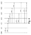
- main control unit CM transmits the system time in steps S400 and S405 to the aggregate control units C1 and C2.
- arrows for steps S400 and S405 are spaced apart, but this does not mean that there must be a time delay between these two steps. Therefore, it is also possible that the output of the system time or a synchronization of the system from all aggregate control units can be understood simultaneously.
- steps S410, S415, S420 and S430 the system time or synchronization is transmitted from the engine control unit C2 to the engine units S21, A21, S22 and A22. As with steps S400 and S405, this transmission may also occur simultaneously and is in Fig. 4 provided with intervals only for reasons of readability.
- the corresponding detection signal having the event time is sent back to the aggregate control unit C2, which in turn can calculate a machining time by itself, and can send it as a machining signal to the engine unit A21 in step S440.
- the main control unit CM calculates this processing time, the detection signal then having to be sent from the unit control unit C2 back to the main control unit CM, calculated there, and sent back to the unit control unit C2.
- This alternative is in Fig. 4 not shown, however, is another way for a communication process.
- Step S445 is represented by a dashed arrow indicating that this step is optional.
- This step corresponds to the situation discussed above that an event at the machine unit S21 may also cause machining in another actuator-type machine unit, for example, machine unit A22, so that two different machine unit processing times based on the same event time and system time of the machine unit Aggregate control unit or main control unit can be calculated.
- step S450 it is shown that in a further advance of the object 03, the machine unit S22 can detect the object 03 and can output a corresponding event time back to the unit control unit C2. This event time may in turn be used in the aggregate control unit C2 to calculate another processing time that may be sent to the machine unit A22 in step S455 so that the machine unit A22 performs an operation at the predetermined second processing time.
Abstract
Description
Die vorliegende Erfindung betrifft eine Bearbeitungseinrichtung und ein Bearbeitungsverfahren zur Bearbeitung von bewegten Objekten, und insbesondere eine Bearbeitungseinrichtung und ein Bearbeitungsverfahren für eine kontinuierliche Vermessung und Bearbeitung bewegter Objekte in einer Durchlaufmaschine mittels Weg-/Zeitmessung in verteilten Systemen.The present invention relates to a processing device and a processing method for processing moving objects, and more particularly to a processing device and a processing method for continuous measurement and processing of moving objects in a continuous machine by means of travel / time measurement in distributed systems.
Vorrichtungen und Verfahren, bei denen ein auf einer Fördereinrichtung befindliches Objekt entlang einer Bearbeitungsstrecke geführt wird, das an einer bestimmten Position erfasst wird und bei einer anderen Position bearbeitet wird, werden im Allgemeinen als Durchlaufmaschinen bzw. Durchlaufverfahren bezeichnet.Devices and methods in which an object located on a conveyor is guided along a processing line which is detected at a certain position and processed at another position are generally referred to as pass-through machines.
Hierbei werden Werkstücke, hier als Objekte bezeichnet, wie zum Beispiel steifes Plattenmaterial, wie Vollholz- bzw. Spanplatten, sogenannte Tischlerplatten, Sperrholzplatten, Verbundplatten aus Holz, Kunststoff oder Metall oder dergleichen auf einer Fördereinrichtung erfasst und daraufhin eine Bearbeitung an denselben durchgeführt.Here, workpieces, referred to here as objects, such as rigid plate material, such as solid wood or chipboard, so-called blockboard, plywood, composite panels made of wood, plastic or metal or the like detected on a conveyor and then performed a processing on the same.
Natürlich kann bei solch einer Durchlaufbearbeitung nicht nur ein Bearbeitungsvorgang an den Objekten ausgeführt werden, sondern verschiedene Bearbeitungen sind möglich, wie zum Beispiel Schneiden, Fräsen, Schleifen, Bohren, etc. Ferner ist es auch möglich, andere Teile auf die Objekte, wie zum Beispiel Werkstücke, aufzubringen bzw. aufzukleben oder aufzuschrauben.Of course, not only a machining operation on the objects can be carried out in such a continuous machining, but various machining operations are possible, such as cutting, milling, grinding, drilling, etc. Further, it is also possible other parts on the objects, such as Workpieces, apply or stick or unscrew.
So kann beispielsweise bei einem automatisierten Ablauf einer Werkstückbearbeitung, das Werkstück an mehrere Bearbeitungsstationen mittels einer Fördereinrichtung mit Band- oder Kettenförderer geführt werden, ohne dass Personen in den Arbeitsablauf eingreifen müssen.Thus, for example, in an automated sequence of workpiece machining, the workpiece can be guided to a plurality of processing stations by means of a conveyor with belt or chain conveyor without people having to intervene in the workflow.
Hierbei ist es äußerst wichtig, dass die genaue Position des Werkstücks auf der Fördereinrichtung immer genau bekannt ist, so dass eine darauf folgende Bearbeitung auch an der richtigen Stelle des Werkstücks ausgeführt wird.Here it is extremely important that the exact position of the workpiece on the conveyor is always accurately known, so that subsequent processing is also carried out at the correct location of the workpiece.
Herkömmlich sind Durchlaufmaschinen mit einer Werkstückerfassung und einem Wegmesssystem ausgestattet, deren Signale einer Steuereinheit zur Verarbeitung zugeführt werden. Im Einlaufbereich der Fördereinrichtung kann dabei ein Werkstück erfasst werden, und ein entsprechendes Signal ausgegeben werden. Da ferner die ungefähre Geschwindigkeit des Transportbandes oder der Transportkette, z.B. durch Messung des zurückgelegten Weges bei verschiedenen Zeitpunkten, ermittelt werden kann, kann dadurch die ungefähre Position des Werkstückes in der Durchlaufmaschine ermittelt werden.Conventionally, pass-through machines are equipped with a workpiece detection system and a position measuring system whose signals are fed to a control unit for processing. In the inlet region of the conveyor, a workpiece can be detected, and a corresponding signal can be output. Further, since the approximate speed of the conveyor belt or transport chain, e.g. can be determined by measuring the distance traveled at different times, thereby the approximate position of the workpiece in the continuous machine can be determined.
Durch Positionierung von Sensoren an der Fördereinrichtung kann somit auch ein Signal ausgegeben werden, das kennzeichnet, dass die Ankunft eines Werkstückes bzw. Objekts bei einem Sensor gemessen wird, was der Position des Werkstückes entspricht. Daraufhin kann einem nachgeschalteten Aktor befohlen werden, zu schalten oder sich zu bewegen, so dass nach einer bestimmten zurückgelegten Strecke des Werkstücks vom Sensor dieses durch den Aktor bearbeitet wird. Somit ist eine kontinuierliche Bearbeitung von Werkstücken in mehreren Bearbeitungsstationen ohne menschliches Eingreifen möglich. Ein Sensor meldet daher, z.B. durch ein Trigger-Signal, dass er gemessen hat und einem Aktor wird befohlen, z.B. durch ein Trigger-Signal, dass er schalten bzw. sich bewegen soll.By positioning sensors on the conveyor can thus be issued a signal that indicates that the arrival of a workpiece or object is measured at a sensor, which corresponds to the position of the workpiece. Then, a downstream actuator can be commanded to switch or move, so that after a certain distance covered the workpiece by the sensor this is processed by the actuator. Thus, a continuous machining of workpieces in multiple processing stations without human intervention is possible. A sensor therefore signals, eg by a trigger signal, that it has measured and an actuator is commanded, eg by a trigger signal, that it should switch or move.
Aus der obigen Beschreibung wird klar, dass die Anzahl der bearbeiteten Teile stark von der Geschwindigkeit der Fördereinrichtung abhängt, das heißt, durch Verdoppeln der Geschwindigkeit lässt sich auch der Durchsatz verdoppeln.From the above description, it is clear that the number of machined parts greatly depends on the speed of the conveyor, that is, by doubling the speed, the throughput can also be doubled.
Jedoch werden Störeinflüsse auf die Position des Werkstücks gravierender und eine Präzision geringer, je höher die Geschwindigkeit ist. Störeinflüsse sind zum Beispiel die Reaktion der Steuerung, der Schlupf bei Vorschub des Werkstücks, Toleranzen im Vorschubtransport und bei der Werkstückerfassung, die sich nur innerhalb gewisser Präzisionsgrenzen erfassen lassen.However, the higher the speed, the more troublesome the position of the workpiece become, and the lower the precision. Disturbing influences are, for example, the reaction of the control, the slippage during feed of the workpiece, tolerances in the feed transport and in the workpiece detection, which can only be detected within certain precision limits.
Somit ist es eine Aufgabe der vorliegenden Erfindung, eine Bearbeitungseinrichtung und ein Bearbeitungsverfahren bereitzustellen, um eine Präzision in der Bestimmung von Position und Länge von sich bewegenden Objekten zu verbessern, ohne dass eine Durchlaufgeschwindigkeit der Objekte reduziert werden muss.Thus, it is an object of the present invention to provide a machining device and a machining method for improving precision in determining position and length of moving objects without having to reduce a passing speed of the objects.
Gemäß einer Ausführungsform umfasst die Bearbeitungseinrichtung eine Steuereinheit mit Zeitgeber zum Ausgeben einer Systemzeit und mindestens zwei mit der Steuereinheit verbundene Maschineneinheiten ausgebildet zum Empfangen der Systemzeit, wobei die erste Maschineneinheit mindestens ein Sensorelement umfasst und ausgebildet ist zum Erfassen eines Ereignisses und zum Ausgeben einer Ereigniszeit basierend auf der Systemzeit, die mit der Erfassung des Ereignisses in Beziehung steht, und die zweite Maschineneinheit mindestens ein Aktorelement umfasst, und ausgebildet ist zum Durchführen eines Betriebs gemäß einer von der Steuereinheit vorgegebenen Bearbeitungszeit, basierend auf der Systemzeit und der Ereigniszeit. Somit gibt eine erste Maschineneinheit mit Sensorelement, wie zum Beispiel ein Sensor, genau an, wann und wo sie gemessen hat und eine zweite Maschineneinheit mit Aktorelement, wie zum Beispiel ein Aktor, kann angewiesen werden zu welchem Zeitpunkt sie einen Betrieb aufnehmen soll. Dadurch kann eine exakte Lage eines Objekts in der Zeit genau erfasst werden und über mindestens eine Steuerung anderen Maschineneinheiten mitgeteilt werden. Dadurch werden eine wesentlich genauere Erfassung eines Objekts und eine wesentliche genauere Ansteuerung von Maschineneinheiten mit Aktorelementen zur Bearbeitung von Objekten ermöglicht, und durch einfaches Arbeiten im Zeitbereich Signalwandlungen eingespart. Hierbei hängt die Präzision in solch einem System nicht von der Laufzeit der Kommunikationsleitungen und Feldbussen zwischen den Komponenten oder der Zykluszeit der Steuerung ab, sondern nur von der Auflösung der Systemszeit, das heißt, der Synchronisierungsgenauigkeit der Maschineneinheiten untereinander.According to one embodiment, the processing device comprises a control unit with a timer for outputting a system time and at least two machine units connected to the control unit configured to receive the system time, wherein the first machine unit comprises at least one sensor element and is designed for Detecting an event and outputting an event time based on the system time related to the detection of the event, and the second machine unit comprises at least one actuator element, and configured to perform an operation according to a machining time predetermined by the control unit based on System time and event time. Thus, a first machine unit with sensor element, such as a sensor, indicates exactly when and where it has measured, and a second machine unit with actuator element, such as an actuator, can be instructed at which time to start operation. As a result, an exact position of an object in time can be accurately detected and communicated to other machine units via at least one control. This allows a much more accurate detection of an object and a significant more accurate control of machine units with actuator elements for processing objects, and saved by simply working in the time domain signal transformations. In this case, the precision in such a system does not depend on the running time of the communication lines and field buses between the components or the cycle time of the control, but only on the resolution of the system time, that is, the synchronization accuracy of the machine units with each other.
Eine Bearbeitungseinrichtung im Sinne der Erfindung ist jedes System, das verteilte Zeiten besitzt, und wo die Zeit eines Auftretens eines Ereignisses, wie zum Beispiel das Erfassen eines Objektes, von einer Einheit zu einer anderen gesendet werden kann, danach verarbeitet werden kann und dann als Bearbeitungszeit nach einem Ereigniszeitpunkt die Durchführung eines Betriebs angeben kann. Somit ist die Bearbeitungseinrichtung insbesondere für eine Durchlaufmaschine geeignet, muss aber nicht notwendigerweise ein Teil einer Durchlaufmaschine sein, da auch Fälle denkbar sind, bei denen ein erstes Objekt erfasst wird, aber ein Betrieb an einem zweiten Objekt durchgeführt wird, das nicht zusammen mit dem ersten Objekt auf einer Fördereinrichtung liegen muss.A processing device in the sense of the invention is any system that has distributed times, and where the time of occurrence of an event, such as the detection of an object, can be sent from one unit to another, and then processed as a processing time after an event time can indicate the execution of an operation. Thus, the processing device is particularly suitable for a pass-through machine, but does not necessarily have to be a part of a pass-through machine, since cases are conceivable in which a first object is detected, but a Operation is performed on a second object, which need not be together with the first object on a conveyor.
Gemäß einem vorteilhaften Beispiel ist die erste Maschineneinheit ausgebildet das Ereignis mit der auf der Systemzeit basierenden Ereigniszeit als Erfassungssignal an die Steuereinheit auszugeben. Somit wird die Steuereinheit der Bearbeitungseinrichtung über die Ereigniszeit informiert, die auf der Systemzeit basiert, und kann andere Maschineneinheiten mit derselben Systemzeit anweisen, einen Betrieb durchzuführen.According to an advantageous example, the first machine unit is designed to output the event with the system time based on the event time as a detection signal to the control unit. Thus, the control unit of the processing device is informed of the event time based on the system time and may instruct other machine units with the same system time to perform an operation.
Gemäß einem vorteilhaften Beispiel berechnet die Steuereinheit die Bearbeitungszeit, basierend auf der Ereigniszeit, wobei bevorzugt die berechnete Bearbeitungszeit als Bearbeitungssignal an die zweite Maschineneinheit ausgegeben wird. Deshalb muss eine Steuereinheit kein exaktes Trigger-Signal an die zweite Maschineneinheit zu einem bestimmten Bearbeitungszeitpunkt ausgeben, sondern es genügt, vor dem Bearbeitungszeitpunkt eine Bearbeitungszeit zu berechnen und diese der zweiten Maschineneinheit vorher mitzuteilen, so dass die zweite Maschineneinheit zur vorgegebenen Zeit selbst den Betrieb aufnimmt. Hierdurch wird eine genauere Ansteuerung des Aktorelements der zweiten Maschineneinheit ermöglicht.According to an advantageous example, the control unit calculates the processing time based on the event time, wherein preferably the calculated processing time is output as a processing signal to the second machine unit. Therefore, a control unit does not have to output an accurate trigger signal to the second machine unit at a certain processing time, but it is sufficient to calculate a processing time before the processing time and inform the second machine unit beforehand so that the second machine unit itself starts operating at the predetermined time , This allows a more accurate control of the actuator element of the second machine unit.
Gemäß einem weiteren vorteilhaften Beispiel umfasst die Bearbeitungseinrichtung eine dritte Maschineneinheit mit einem zweiten Sensorelement und eine vierte Maschineneinheit mit einem zweiten Aktorelement, wobei die dritte und vierte Maschineneinheit ausgebildet sind, die Systemzeit von der Steuereinheit zu empfangen, und die Steuereinheit ausgebildet ist, basierend auf dem Ereignis und der Ereigniszeit, die Maschineneinheit mit Aktorelement auszuwählen, der die Bearbeitungszeit mitzuteilen ist. Da die Maschineneinheiten mit Aktorelement nur über die Bearbeitungszeit informiert werden und nicht beim Bearbeitungszeitpunkt von der Steuereinheit getriggert werden, kann die Bearbeitungszeit zu einem willkürlichen Zeitpunkt vor dem Bearbeitungszeitpunkt gesendet werden, so dass keine Engpässe auf einer Kommunikationsleitung oder Feldbus entstehen, und eine exakte Ansteuerung aufgrund der gleichen Zeit in den Maschineneinheiten gewährleistet wird.According to a further advantageous example, the processing device comprises a third machine unit with a second sensor element and a fourth machine unit with a second actuator element, wherein the third and fourth machine units are designed to receive the system time from the control unit, and the control unit is designed based on the Event and the event time to select the machine unit with actuator element to which the processing time is to be notified. Since the machine units with actuator element inform only about the processing time and are not triggered by the control unit at the time of processing, the processing time may be sent at an arbitrary time prior to the processing time so that bottlenecks do not arise on a communication line or field bus, and an accurate drive is ensured in the machine units due to the same time.
Gemäß einem weiteren vorteilhaften Beispiel, bilden die erste und zweite Maschineneinheit ein Bearbeitungsaggregat, das bevorzugt eine Aggregatsteuereinheit umfasst. Somit kann die Signalverarbeitung zwischen der Steuereinheit und der Aggregatsteuereinheit aufgeteilt werden, wodurch die Steuereinheit entlastet wird.According to a further advantageous example, the first and second machine units form a processing unit, which preferably comprises an aggregate control unit. Thus, the signal processing between the control unit and the unit control unit can be divided, whereby the control unit is relieved.
Gemäß einem weiteren vorteilhaften Beispiel ist die Aggregatsteuereinheit ausgebildet, mit der Steuereinheit über ein Bussystem zu kommunizieren, und über das Bussystem die Systemzeit zu empfangen. Somit kann die Systemzeit von der Steuereinheit an eine Aggregatsteuereinheit ausgegeben werden, die ferner die daran angeschlossenen Maschineneinheiten mit der Systemzeit versorgt, so dass ohne weitere Kommunikationsleitungen zur Steuereinheit die Bearbeitungseinrichtung durch weitere Maschineneinheiten an der Aggregatsteuereinheit erweitert werden kann.According to a further advantageous example, the aggregate control unit is designed to communicate with the control unit via a bus system and to receive the system time via the bus system. Thus, the system time can be output from the control unit to an aggregate control unit, which also supplies the machine units connected thereto with the system time, so that without further communication lines to the control unit, the processing means can be extended by further machine units on the unit control unit.
Gemäß einem weiteren vorteilhaften Beispiel synchronisiert die Steuereinheit die Maschineneinheiten. Dadurch muss eine Systemzeit nur einmal von einer Steuereinheit ausgegeben werden, da diese Zeit in den einzelnen Maschineneinheiten durch ein einfaches Synchronisierungssignal zu späteren Zeitpunkten synchronisiert werden kann.According to a further advantageous example, the control unit synchronizes the machine units. As a result, a system time must be issued only once by a control unit, since this time can be synchronized in the individual machine units by a simple synchronization signal at later times.
Gemäß einem weiteren vorteilhaften Beispiel umfasst die erste Maschineneinheit einen ersten Speicher zum Speichern von Ereignissen und Ereigniszeiten. Somit muss ein erfasstes Ereignis und/oder Ereigniszeit nicht sofort an eine Steuereinheit weitergegeben werden, sondern kann in der Maschineneinheit zwischengespeichert werden, so dass auch zwei oder mehr Ereignisse und/oder Ereigniszeiten zusammen an eine Steuereinheit gesendet werden können.According to a further advantageous example, the first machine unit comprises a first memory for storing events and event times. Thus, a detected event and / or event time does not have to be immediately addressed to a Control unit can be passed, but can be cached in the machine unit, so that two or more events and / or event times can be sent together to a control unit.
Gemäß einem weiteren vorteilhaften Beispiel umfasst die zweite Maschineneinheit einen zweiten Speicher zum Speichern von Bearbeitungszeiten. Durch Speichern mehrerer Bearbeitungszeiten können verschiedene Betriebe zu verschiedenen Bearbeitungszeiten, wie im Speicher festgelegt, nacheinander ohne weitere Kommunikation mit einer Steuereinheit abgearbeitet werden.According to a further advantageous example, the second machine unit comprises a second memory for storing processing times. By storing a plurality of processing times, different operations at different processing times, as determined in the memory, can be successively processed without further communication with a control unit.
Gemäß einem weiteren vorteilhaften Beispiel entspricht die Systemzeit der realen Weltzeit. Durch Verwenden der realen Weltzeit kann gewährleistet werden, dass auch zwei weit voneinander entfernte Maschineneinheiten, die jeweils die Weltzeit empfangen, dieselbe Zeit haben, wobei eine Ereigniszeit an ein größeres Netzwerk ausgegeben werden kann, und eine Bearbeitungszeit von einem größeren Netzwerk, wie zum Beispiel dem Internet, erhalten und weiter übertragen werden kann.According to another advantageous example, the system time corresponds to the real world time. By using real-world time, it is possible to ensure that even two machine units far apart from each other, each receiving the world time, have the same time, one event time can be output to a larger network, and one processing time from a larger network, such as Internet, received and can be transferred.
Gemäß einer anderen Ausführungsform ist die Bearbeitungseinrichtung in einer Durchlaufmaschine enthalten. Somit lassen sich die oben beschriebenen Vorteile auch bei einer Durchlaufmaschine erzielen.According to another embodiment, the processing device is contained in a continuous machine. Thus, the advantages described above can also be achieved in a continuous machine.
Gemäß einem weiteren vorteilhaften Beispiel umfasst die Durchlaufmaschine einen Objektsensor zum Erfassen eines Objekts auf einer Fördereinrichtung und zum Ausgeben eines Objekt-Erfassungssignals enthaltend eine Objekt-Erfassungszeit, basierend auf der Systemzeit. Somit kann die exakte Position eines Objekts zu einem bestimmten Zeitpunkt ermittelt und leicht an andere Maschineneinheiten gesandt werden.According to a further advantageous example, the pass-through machine comprises an object sensor for detecting an object on a conveyor and for outputting an object detection signal including an object detection time based on the system time. Thus, the exact position of an object at a particular time can be determined and easily sent to other machine units.
Gemäß einem weiteren vorteilhaften Beispiel umfasst die Durchlaufmaschine einen Lagegeber zum Ausgeben eines Messsignals entsprechend einer Messung einer Position einer Fördereinrichtung an die Steuereinheit, wobei das Messsignal eine Messzeit, basierend auf der Systemzeit enthält, die mit der Messung in Beziehung steht, und wobei die Steuereinheit bevorzugt ausgebildet ist, eine Position eines Objekts auf der Fördereinrichtung zu unterschiedlichen Zeiten zu berechnen durch Verwenden des Messsignals und des Erfassungssignals oder des Objekt-Erfassungssignals. Durch Messen der Position der Fördereinrichtung zu kurz aufeinander folgenden Messzeiten lässt sich die Geschwindigkeit der Fördereinrichtung ermitteln und durch mehrere Messungen auch deren Schwankung, so dass die Position eines Objekts zu verschiedenen Zeiten auf der Fördereinrichtung ermittelt werden kann. Ferner kann die Geschwindigkeitsinformation in der Steuereinheit zur Berechnung der Bearbeitungszeit verwendet werden.According to a further advantageous example, the pass-through machine comprises a position sensor for outputting a measurement signal corresponding to a measurement of a position of a conveyor to the control unit, the measurement signal containing a measurement time based on the system time related to the measurement, and wherein the control unit is preferred is configured to calculate a position of an object on the conveyor at different times by using the measurement signal and the detection signal or the object detection signal. By measuring the position of the conveyor at too short successive measuring times, the speed of the conveyor can be determined and by several measurements also their variation, so that the position of an object at different times on the conveyor can be determined. Further, the speed information may be used in the control unit to calculate the processing time.
Gemäß einer anderen Ausführungsform, umfasst ein Bearbeitungsverfahren ein Ausgeben einer definierten Systemzeit von einer Steuereinheit mit Zeitgeber an mindestens zwei Maschineneinheiten, ein Erfassen eines Ereignisses mit der ersten Maschineneinheit, ein Ausgeben einer Ereigniszeit, basierend auf der Systemzeit, die mit der Erfassung des Ereignisses in Beziehung steht, von der ersten Maschineneinheit an die Steuereinheit, und Durchführen eines Betriebs gemäß einer von der Steuereinheit vorgegebenen Bearbeitungszeit, basierend auf der Systemzeit und der Ereigniszeit durch die zweite Maschineneinheit. Insbesondere ist das Verfahren dazu geeignet in einer Durchlaufmaschine ausgeführt zu werden. Somit lässt sich ein einfaches und verlässliches Verfahren für eine präzise Positionsbestimmung für Objekte in einer Durchlaufmaschine verwirklichen.According to another embodiment, a processing method includes outputting a defined system time from a controller having timers on at least two machine units, detecting an event with the first machine unit, outputting an event time based on the system time related to the detection of the event from the first machine unit to the control unit, and performing an operation according to a processing time predetermined by the control unit, based on the system time and the event time by the second machine unit. In particular, the method is suitable to be carried out in a continuous machine. Thus, a simple and reliable method for a precise position determination for objects in a continuous machine can be realized.
Weitere vorteilhafte Merkmale der Erfindung werden in den Ansprüchen offenbart.Further advantageous features of the invention are disclosed in the claims.
- Fig. 1Fig. 1
- zeigt schematisch eine Bearbeitungseinrichtung gemäß einer Ausführungsform der Erfindung.schematically shows a processing device according to an embodiment of the invention.
- Fig. 2Fig. 2
- zeigt ein Flussdiagramm, das die Schritte eines Bearbeitungsverfahrens gemäß einer weiteren Ausführungsform der Erfindung zeigt.shows a flowchart showing the steps of a machining method according to another embodiment of the invention.
- Fig. 3Fig. 3
- zeigt eine Durchlaufmaschine mit der Bearbeitungseinrichtung gemäß einer weiteren Ausführungsform der Erfindung.shows a continuous machine with the processing device according to another embodiment of the invention.
- Fig. 4Fig. 4
- zeigt ein Abfolgediagramm der Schritte in einer Durchlaufmaschine gemäß einer beispielhaften Ausführungsform der vorliegenden Erfindung.FIG. 10 is a sequence diagram of the steps in a pass-through machine according to an exemplary embodiment of the present invention. FIG.
Bevorzugte Ausführungsformen der vorliegenden Erfindung werden nachfolgend ausführlich unter Bezugnahme auf die begleitenden Zeichnungen beschrieben. Dabei sind in verschiedenen Zeichnungen gleiche oder entsprechende Bauteile jeweils mit den gleichen oder ähnlichen Bezugszeichen bezeichnet.Preferred embodiments of the present invention will be described below in detail with reference to the accompanying drawings. In this case, the same or corresponding components are denoted in each case by the same or similar reference numerals in different drawings.
Die bevorzugten Ausführungsformen der Erfindung, die im Detail unten beschrieben werden, werden ausführlich mit Bezug auf eine Bearbeitungseinrichtung und eine Durchlaufmaschine beschrieben. Jedoch wird bemerkt, dass die folgende Beschreibung nur Beispiele enthält und nicht als die Erfindung einschränkend angesehen werden sollte.The preferred embodiments of the invention, which will be described in detail below, will be described in detail with reference to a processing device and a continuous machine. However, it is noted that the following description contains only examples and should not be taken as limiting the invention.
Beispielsweise erkennt der Fachmann, dass in der vorliegenden Erfindung alle Einheiten der Bearbeitungseinrichtung die gleiche Systemzeit besitzen, dies bedeutet, dass die Zeit in den Einheiten überall gleich ist. Deshalb kann nach Erfassung eines Ereignisses bei einer ersten Maschineneinheit eine zweite Maschineneinheit bestimmt werden, die einen Befehl mit einer Zeitvorgabe nach der Erfassung des Ereignisses bekommt, um dann irgendeinen Betrieb auszuführen.For example, those skilled in the art will recognize that in the present invention, all units of the processing equipment have the same system time, which means that the time in the units are the same everywhere. Therefore, upon detection of an event at a first machine unit, a second machine unit may be designated to receive a command with a timing following the detection of the event to then perform any operation.
Es sei hier bemerkt, dass der Betrieb nicht notwendigerweise an einem Objekt ausgeführt werden muss, das das Ereignis bei der ersten Maschineneinheit ausgelöst hat. Es ist auch denkbar, dass es sich bei dem Auslösen dieses Ereignisses um ein anderes Objekt handelt. So kann zum Beispiel ein erstes Objekt ein Ereignis zu einer genau erfassbaren Zeit, der Ereigniszeit, auslösen, wodurch die zweite Maschineneinheit eine Bearbeitungszeit empfängt, zu der ein Betrieb an beispielsweise einer zweiten Maschineneinheit durchzuführen ist. Dabei muss der Zeitunterschied zwischen der Ereigniszeit und der Bearbeitungszeit nur so groß gewählt werden, dass eine Kommunikation des Befehls zum Durchführen des Betriebs noch rechtzeitig an der zweiten Maschineneinheit ankommen kann, bevor die zweite Maschineneinheit einen Betrieb durchführen soll.It should be noted here that the operation does not necessarily have to be performed on an object that triggered the event at the first machine unit. It is also conceivable that the triggering of this event is another object. For example, a first object may trigger an event at an accurately detectable time, the event time, whereby the second machine unit receives a processing time to operate on, for example, a second machine unit. In this case, the time difference between the event time and the processing time only has to be chosen so large that a communication of the command for performing the operation can arrive at the second machine unit in time before the second machine unit is to perform an operation.
Die Bearbeitungseinrichtung kann, muss aber daher nicht notwendigerweise ein Teil einer herkömmlichen Durchlaufmaschine sein, da sie sich auch für andere Systeme eignet, in denen ein erstes Objekt erfasst wird, aber ein Betrieb an einem zweiten Objekt durchgeführt wird, das nicht zusammen mit dem ersten Objekt auf einer Fördereinrichtung liegen muss. Eine Durchlaufmaschine kann zum Beispiel eine Durchlaufmaschine zur Bearbeitung von plattenförmigen Werkstücken, wie z.B. Vollholz- bzw. Spanplatten, sogenannte Tischlerplatten, Sperrholzplatten, Verbundplatten aus Holz, Kunststoff oder Metall oder dergleichen sein.The processing device may, but does not necessarily have to, be part of a conventional pass-through machine, since it is also suitable for other systems in which a first object is detected but an operation is performed on a second object that is not associated with the first object must lie on a conveyor. For example, a pass-through machine may include a pass-through machine for processing plate-shaped workpieces, such as e.g. Solid wood or chipboard, so-called Tischlerplatten, plywood panels, composite panels of wood, plastic or metal or the like.
Im Folgenden wird, aus Gründen einer einfachen Darstellbarkeit, die vorliegende Erfindung mit Hilfe einer Bearbeitungseinrichtung und einer Durchlaufmaschine beschrieben, wobei eine Bearbeitungseinrichtung für die Durchlaufmaschine eine Steuereinheit mit Zeitgeber umfasst, der eine Systemzeit erzeugt, die ausgegeben wird an mindestens zwei Maschineneinheiten. Somit haben die erste und zweite Maschineneinheit die gleiche Systemzeit, und das Erfassen eines Objekts von der ersten Maschineneinheit kann genau durch eine Ereigniszeit, basierend auf der Systemzeit, definiert werden.In the following, for reasons of simplicity, the present invention will be described with the aid of a processing device and a pass-through machine in which a processing device for the pass-through machine comprises a control unit with a timer which generates a system time which is output on at least two machine units. Thus, the first and second machine units have the same system time, and the detection of an object from the first machine unit can be accurately defined by an event time based on the system time.
Bei dem Beispiel der Durchlaufmaschine, die Objekte mit gleich bleibender Geschwindigkeit transportiert, kann so aus dem Ort der ersten Maschineneinheit und der Ereigniszeit abgeleitet werden, wann sich dasselbe Objekt bei der zweiten Maschineneinheit befindet. Diese Zeit, im Folgenden als Bearbeitungszeit bezeichnet, wird beispielsweise von der Steuereinheit berechnet und an die zweite Maschineneinheit gesendet, so dass diese das Objekt zu der definierten Bearbeitungszeit bearbeiten kann.In the example of the pass-through machine, which transports objects at a constant speed, it can thus be deduced from the location of the first machine unit and the event time when the same object is located at the second machine unit. This time, referred to below as the processing time, is calculated by the control unit, for example, and sent to the second machine unit so that it can process the object at the defined processing time.
Somit kann eine Position des Objekts genau festgestellt und übermittelt werden, ohne dass eine Steuereinheit Trigger-Signale verarbeiten muss, die angeben, dass ein Sensor gerade gemessen hat, oder ein Aktor jetzt schalten oder sich bewegen soll.Thus, a position of the object can be accurately detected and transmitted without a control unit having to process trigger signals indicating that a sensor has just been measured, or an actuator should now shift or move.
Diese Einheiten können individuelle Einheiten darstellen, die miteinander verbunden sind, oder können auch auf eine passende Art und Weise zusammengefasst werden, wobei zum Beispiel die Steuereinheit in einer der Maschineneinheiten integriert sein kann.These units may represent individual units that are interconnected, or may also be summarized in an appropriate manner, for example, wherein the control unit may be integrated in one of the machine units.
In
Die Steuereinheit C umfasst den Zeitgeber ZG zum Ausgeben einer Systemzeit. Die Steuereinheit C dient zur Steuerung der Bearbeitungseinrichtung 100 und kann beispielsweise eine Bearbeitungszeit, basierend auf der vom Zeitgeber gegebenen Systemzeit, vorgeben.The control unit C includes the timer ZG for outputting a system time. The control unit C is used to control the
Die Steuereinheit C kann realisiert werden durch einen Prozessor, Computer oder eine integrierte Schaltung, wie zum Beispiel eine anwendungsspezifische integrierte Schaltung (ASIC) oder durch Software oder eine passende Kombination aus den obigen.The control unit C can be realized by a processor, computer or integrated circuit, such as an application specific integrated circuit (ASIC) or by software or an appropriate combination of the above.
Die erste Maschineneinheit S11 umfasst mindestens ein Sensorelement SE11 und ist ausgebildet zum Erfassen eines Ereignisses und zum Ausgeben einer Ereigniszeit, basierend auf der Systemzeit, die mit der Erfassung des Ereignisses in Beziehung steht. Im einfachsten Fall handelt es sich bei der ersten Maschineneinheit um einen Sensor.The first machine unit S11 includes at least one sensor element SE11 and is configured to detect an event and output an event time based on the system time related to the detection of the event. In the simplest case, the first machine unit is a sensor.
Beispielsweise kann es sich bei dem Ereignis um das Erfassen einer Vorderflanke oder Hinterflanke eines Objekts, zum Beispiel einer Holzplatte, handeln. Die erste Maschineneinheit kann den Ereigniszeitpunkt speichern, der ein Zeitpunkt zu der herrschenden Systemzeit ist und gibt eine Ereigniszeit aus. Bei der ausgegebenen Ereigniszeit muss es sich nicht um den Ereigniszeitpunkt selbst handeln, da es auch einfach möglich ist, Zeit- oder Taktdifferenz auszugeben, die von einem Referenztakt bzw. Referenzuhrzeit gemessen werden. Beispielsweise kann ein Wert von 5 Takten oder 5 Sekunden nach z.B. einer letzten Synchronisierung ausgegeben werden, wobei die Synchronisierung bei allen Einheiten zur gleichen Zeit erfolgt ist.For example, the event may involve the detection of a leading edge or trailing edge of an object, for example a wooden panel. The first machine unit may store the event time, which is a time at the prevailing system time, and outputs an event time. The output event time does not have to be the event time itself, as it is also easy to output time or clock difference from a reference clock or reference time be measured. For example, a value of 5 clocks or 5 seconds after, for example, a last synchronization may be output, with the synchronization occurring at all units at the same time.
Das Ereignis kann mit der auf der Systemzeit basierenden Ereigniszeit als Erfassungssignal an die Steuereinheit C ausgegeben werden. Das Erfassungssignal enthält dann eine Information über das Ereignis, wobei eine einfache Angabe wie Ja/Nein genügt, das heißt, Flanke erfasst oder nicht, sowie die Ereigniszeit, die wie oben angegeben, entweder als Absolutzeit angegeben werden kann oder als eine Differenzzeit zu einer Referenzzeit, wie zum Beispiel einem Synchronisierungsvorgang.The event may be output to the control unit C as the detection signal based on the system time-based event time. The detection signal then contains information about the event, where a simple indication such as yes / no is sufficient, that is, edge detected or not, and the event time, which as stated above, can be given either as an absolute time or as a difference time to a reference time , such as a synchronization process.
Das Sensorelement SE11 in der ersten Maschineneinheit S11 kann ein handelsübliches Sensorelement sein, das in Sensoren in der Automatisierungstechnik verwendet wird. Beispielsweise kann ein optisches Sensorelement verwendet werden, das eine Taktung von beispielsweise 5 kHz aufweist, was ein limitierender Faktor für die Genauigkeit der Messung ist.The sensor element SE11 in the first machine unit S11 may be a commercially available sensor element that is used in sensors in automation technology. For example, an optical sensor element having a clocking of, for example, 5 kHz may be used, which is a limiting factor for the accuracy of the measurement.
Die zweite Maschineneinheit A11 umfasst mindestens ein Aktorelement AE11 und ist ausgebildet zum Durchführen eines Betriebs gemäß einer von der Steuereinheit vorgegebenen Bearbeitungszeit, basierend auf der Systemzeit und der Ereigniszeit. Im einfachsten Fall ist die zweite Maschineneinheit A11 ein Aktor, also das wandlerbezogene Gegenstück zu einem Sensor, der einen Betrieb zu einer vorgegebenen Bearbeitungszeit ausführt. Bei dem Betrieb kann es sich beispielsweise um ein Bearbeiten im Sinne von Stanzen, Lochen, Schneiden, Kleben, Bohren etc. handeln, aber andere Betriebe, wie ein Umleiten, Ausgeben oder Entfernen eines Objekts, das zu der Bearbeitungszeit bei der zweiten Maschineneinheit vorliegt, sind auch denkbar. Das Aktorelement kann z.B. ein Element sein, das solche und ähnliche Funktionen ausführen kann.The second machine unit A11 comprises at least one actuator element AE11 and is designed to perform an operation according to a processing time predetermined by the control unit, based on the system time and the event time. In the simplest case, the second machine unit A11 is an actuator, ie the converter-related counterpart to a sensor which performs an operation at a predetermined processing time. The operation may be, for example, machining in the sense of punching, punching, cutting, gluing, drilling, etc., but other operations, such as redirecting, dispensing or removing an object that is present at the processing time at the second machine unit, are also possible. The actuator element may be, for example, an element that can perform such and similar functions.
Genauer gesagt empfängt die zweite Maschineneinheit A11 die Bearbeitungszeit, die auf der Systemzeit und der Ereigniszeit basiert, und vergleicht die vorgegebene Bearbeitungszeit mit einer Ist-Zeit, der beim Empfang der Bearbeitungszeit herrschenden Systemzeit, die die gleiche ist für alle Einheiten in der Bearbeitungseinrichtung 100 und wartet mit dem Betrieb, bis die vorgegebene Bearbeitungszeit der Systemzeit entspricht. Bei der Bearbeitungszeit kann es sich daher auch, wie mit Bezug auf die Ereigniszeit oben beschrieben, um eine absolute Zeit handeln oder eine relative Zeit, das heißt, um eine von einer Referenzzeit gemessene Zeitdifferenz.More specifically, the second machine unit A11 receives the processing time based on the system time and the event time, and compares the predetermined processing time with an actual time, the system time prevailing upon receiving the processing time, which is the same for all units in the
In einer speziellen Ausführungsform ist die Steuereinheit C ausgebildet, basierend auf der Ereigniszeit, die Bearbeitungszeit zu berechnen. Zur Berechnung der Bearbeitungszeit enthält die Steuereinheit C einen Prozessor, Computer oder integrierte Schaltung, wie oben beschrieben, und kann, zum Beispiel bei einer Durchlaufmaschine mit Fördereinrichtung, unter Verwendung der Geschwindigkeit der Fördereinrichtung, bestimmen, wann ein bei der ersten Maschineneinheit S11 erfasstes Objekt bei der zweiten Maschineneinheit ankommt. Diese Ankunftszeit entspricht sodann der Bearbeitungszeit, nämlich der Zeit, zu der ein Objekt von der zweiten Maschineneinheit bearbeitet werden kann. Um dies zu erreichen, ist die Steuereinheit C ausgebildet, die Bearbeitungszeit als Bearbeitungssignal an die zweite Maschineneinheit A11 auszugeben.In a specific embodiment, the control unit C is designed to calculate the processing time based on the event time. For calculating the processing time, the control unit C includes a processor, computer or integrated circuit as described above, and may determine when an object detected at the first machine unit S11, for example, in a conveyorized conveyor machine using the conveyor speed the second machine unit arrives. This arrival time then corresponds to the processing time, namely the time at which an object can be processed by the second machine unit. In order to achieve this, the control unit C is designed to output the processing time as a processing signal to the second machine unit A11.
Wenn die Bearbeitungszeit erreicht ist, führt die zweite Maschineneinheit dann einen der oben beschriebenen Betriebe aus.When the processing time is reached, the second machine unit then executes one of the operations described above.
Somit teilt die erste Maschineneinheit S11 nicht mit, dass sie gemessen hat, wie es herkömmlich der Fall ist, sondern wann bzw. was sie wann gemessen hat und gibt die genaue Zeit der Messung aus, die von allen Einheiten in der Bearbeitungseinrichtung verstanden wird, da alle auf der gleichen Systemzeit sind. Der zweiten Maschineneinheit A11 wird nicht mitgeteilt, dass sie jetzt schalten bzw. sich bewegen soll, sondern ihr wird mitgeteilt, wann sie sich wohin bewegen soll durch die vorgegebene Bearbeitungszeit, basierend auf der Systemzeit, die bei allen Einheiten der Bearbeitungseinrichtung 100 gleich ist.Thus, the first machine unit S11 does not report that it has measured, as is conventionally the case, but when or what has measured when, and gives the exact time the measurement, which is understood by all units in the processing device, since all are on the same system time. The second machine unit A11 is not informed that it should now shift or move, but is informed when it should go where by the predetermined processing time, based on the system time, which is the same for all units of the
Anstatt eines regelmäßigen Aussendens der Systemzeit, um zu gewährleisten, dass alle Einheiten auf der gleichen Zeit sind, kann es bevorzugt sein, die Maschineneinheiten durch ein einfaches Synchronisierungssignal regelmäßig zu synchronisieren. Dafür kann die Steuereinheit C zum Synchronisieren ausgebildet sein.Rather than periodically broadcasting the system time to ensure that all units are at the same time, it may be preferable to periodically synchronize the machine units with a simple synchronization signal. For this, the control unit C can be designed to synchronize.
Ferner kann die erste Maschineneinheit S11 einen nicht gezeigten ersten Speicher umfassen zum Speichern der Ereignisse und von Ereigniszeiten. Dies kann vor allem für den Fall vorteilhaft sein, dass kurze Objekte mit kurzen Abständen zwischen Vorder- und Hinterflanke oder kurze Abstände zwischen zwei Objekten erfasst und zwischengespeichert werden können, so dass nicht jedes erfasste Ereignis oder Ereigniszeit sofort ausgegeben werden muss, sondern zwischengespeichert werden kann und dann mehrere Ereignisse und/oder ihre Ereigniszeiten auf einmal ausgegeben werden können.Further, the first machine unit S11 may include a first memory, not shown, for storing the events and event times. This can be advantageous in particular in the event that short objects with short distances between leading and trailing edges or short distances between two objects can be detected and buffered, so that not every recorded event or event time must be output immediately, but can be temporarily stored and then multiple events and / or their event times can be issued at once.
Hierbei muss lediglich gewährleistet werden, dass die Zeit bis zur Übertragung der Ereigniszeit an die Steuereinheit C plus eine Verarbeitungszeit in der Steuereinheit und eine Zeit zum Senden der berechneten Bearbeitungszeit an die zweite Maschineneinheit A11, kürzer ist als die Zeit, die das Objekt braucht, um von der ersten Maschineneinheit S11 zur zweiten Maschineneinheit A11, zum Beispiel auf einer Fördereinrichtung, zu gelangen.Here, it merely has to be ensured that the time until transmission of the event time to the control unit C plus a processing time in the control unit and a time for sending the calculated processing time to the second machine unit A11 is shorter than the time it takes the object to from the first machine unit S11 to the second machine unit A11, for example on a conveyor.
Die zweite Maschineneinheit A11 kann auch einen nicht gezeigten zweiten Speicher umfassen zum Speichern von Bearbeitungszeiten. Somit können, ähnlich zu dem ersten Speicher, mehrere Bearbeitungszeiten und/oder ihre Bearbeitungssollwerte zwischengespeichert werden, die dann je nach Bedarf abgearbeitet werden können. Beispielsweise können drei Bearbeitungszeiten und deren Sollwerte gespeichert werden, so dass, wenn die Systemzeit jeweils eine der Bearbeitungszeiten erreicht, ein dem Sollwert entsprechender Betrieb durchgeführt wird.The second machine unit A11 may also include a second memory, not shown, for storing processing times. Thus, similar to the first memory, several processing times and / or their processing setpoints can be cached, which can then be processed as needed. For example, three processing times and their setpoint values can be stored, so that when the system time reaches one of the processing times, an operation corresponding to the desired value is performed.
Vorteilhaft kann es sich bei der Systemzeit um die reale Weltzeit handeln, das bedeutet, dass alle Einheiten in der Bearbeitungseinrichtung 100 beispielsweise durch ein Funksignal von einer Atomuhr, wie die Atomuhr der Physikalisch-Technischen Bundesanstalt, synchronisiert werden können.Advantageously, the system time can be the real world time, which means that all units in the
Wie später beschrieben, können die erste und zweite Maschineneinheit ein Bearbeitungsaggregat bilden. Dies bedeutet, dass dann nur eine bidirektionale Kommunikationsleitung zwischen dem Bearbeitungsaggregat und der Steuereinheit C nötig wäre. In einer weiteren Ausführungsform kann das Bearbeitungsaggregat eine Aggregatsteuereinheit umfassen, was später mit Bezug auf
Als nächstes wird in
Dieses Verfahren kann beispielsweise von der in
In einem ersten Schritt 210 wird eine definierte Systemzeit von einer Steuereinheit C mit Zeitgeber ZG an mindestens zwei Maschineneinheiten S11 und A11 ausgegeben. Wie oben beschrieben, kann die Systemzeit die reale Weltzeit sein, wobei nur immer darauf geachtet werden muss, dass die Einheiten des Systems, nämlich Steuereinheit und Maschineneinheiten, die gleiche Zeit anzeigen. Die Systemzeit kann über eine feste Kommunikationsleitung, wie zum Beispiel einem Feldbus, übertragen werden, oder auch drahtlos.In a
In einem nachfolgenden Schritt 220 wird ein Ereignis mit der ersten Maschineneinheit S11 erfasst. Beispielsweise kann, wie oben beschrieben, ein sich auf einer Fördereinrichtung einer Durchlaufmaschine befindliches Objekt erfasst werden, wenn beispielsweise seine Vorderflanke detektiert wird.In a
Sodann kann in einem folgenden Schritt 230 die Zeit, die mit der Erfassung des Ereignisses in Beziehung steht, als Ereigniszeit basierend auf der Systemzeit von der ersten Maschineneinheit S11 an die Steuereinheit C ausgegeben werden. Hierbei handelt es sich nicht um ein einfaches Trigger-Signal, das angibt, dass zum Beispiel die Vorderflanke eines Objekts erfasst wurde, sondern um ein Signal mit der genauen Zeit, zu der die Vorderflanke erfasst wurde.Then, in a following
Deshalb muss die Steuereinheit nicht eine Übertragungszeit in einer Kommunikationsleitung von der ersten Maschineneinheit zur Steuereinheit, wie beim Trigger-Signal, in Betracht ziehen, da die übertragene Ereigniszeit sich trotz möglicher Verzögerungen durch eine Kommunikationsleitung nicht ändert. Es muss lediglich sichergestellt werden, dass die Zeit, die die Ereigniszeit zur Steuereinheit braucht, und von der Steuereinheit zu der zweiten Maschineneinheit geringer ist, als die Zeit, die das Objekt von der ersten Maschineneinheit zur zweiten Maschineneinheit braucht.Therefore, the control unit need not consider a transmission time in a communication line from the first machine unit to the control unit, such as the trigger signal, since the transmitted event time does not change despite possible delays through a communication line. It only needs to be ensured that the time that the event time to the control unit takes and from the control unit to the second machine unit is less than the time that the object needs from the first machine unit to the second machine unit.
In dem nächsten Schritt 240 wird ein Betrieb gemäß einer von der Steuereinheit C vorgegebenen Bearbeitungszeit, basierend auf der Systemzeit und der Ereigniszeit, durch die zweite Maschineneinheit durchgeführt. Wie schon oben beschrieben, wird die Bearbeitungszeit, basierend auf der Ereigniszeit und der Systemzeit, bevorzugt durch die Steuereinheit berechnet. Danach wird die Bearbeitungszeit beispielsweise als Bearbeitungssignal von der Steuereinheit C an die zweite Maschineneinheit ausgegeben. Somit wird ein effizientes Verfahren zum akkuraten Vermessen und Bearbeiten von Objekten bereitgestellt.In the
Als Nächstes wird eine Durchlaufmaschine 300 mit einer darin integrierten Bearbeitungseinrichtung gemäß einer weiteren Ausführungsform der Erfindung mit Bezug auf
Die in
In
Wie oben beschrieben, können die erste und zweite Maschineneinheit auch als Bearbeitungsaggregat 310 aufgefasst werden, das bevorzugt die Aggregatsteuereinheit C1 umfasst. Diese Aggregatsteuereinheit C1 und die Hauptsteuereinheit CM können die Funktionen der in
Natürlich wäre auch in der Durchlaufmaschine von
Die in
Wie in
Die Aggregatsteuereinheit C1 ist ferner ausgebildet, basierend auf dem Ereignis und der Ereigniszeit, die Maschineneinheit mit Aktorelement A11, A12 auszuwählen, der die Bearbeitungszeit mitzuteilen ist.The aggregate control unit C1 is further configured to select, based on the event and the event time, the engine unit with actuator element A11, A12 to be notified of the machining time.
Herkömmlich wird einem Sensor, zum Beispiel Maschineneinheit S11, ein Aktor, zum Beispiel Maschineneinheit A11, zugewiesen, so dass ein durch die Maschineneinheit S11 erfasstes Ereignis der Maschineneinheit A11 mitgeteilt wird. Jedoch ist es auch möglich, dieses Ereignis der vierten Maschineneinheit A12 mitzuteilen, was basierend auf der Art des Ereignisses durchgeführt werden kann.Conventionally, a sensor, for example, machine unit S11, is assigned an actuator, for example, machine unit A11, so that an event detected by machine unit S11 is notified to machine unit A11. However, it is also possible to notify this event to the fourth machine unit A12, which may be performed based on the type of event.
Beispielsweise kann, falls es sich bei dem Ereignis um eine Detektion einer Vorderflanke eines Objekts handelt, diese Information für die zweite und vierte Maschineneinheit wichtig sein, wobei bei der zweiten Maschineneinheit beispielsweise ein Loch in das Objekt gebohrt wird und bei der vierten Maschineneinheit dieses Loch mit einem Kleber gefüllt wird.For example, if the event is a detection of a leading edge of an object, that information may be important to the second and fourth machine units, with the second machine unit, for example, drilling a hole in the object and drilling the hole in the fourth machine unit an adhesive is filled.
Die in
In
Die zweite Kommunikationsleitung 330 ist bidirektional ausgebildet und sendet Signale von den Aggregatsteuereinheiten C1 bis Cn zur Hauptsteuereinheit CM und von der Hauptsteuereinheit zu den Aggregatsteuereinheiten. Beispielsweise werden die Erfassungssignale von den Aggregatsteuereinheiten an die Hauptsteuereinheit gesendet, wobei die Hauptsteuereinheit CM Bearbeitungssignale an die Aggregatsteuereinheiten C1 bis Cn senden kann.The
Natürlich können die beiden Funktionen der Kommunikationsleitungen 330 und 340 auch in einem einzigen Bussystem integriert werden. Hierbei können auch relativ langsame Feldbusse und unterschiedliche Steuereinheiten verwendet werden, da wie vorher beschrieben, es in der vorliegenden Erfindung nicht auf den genauen Empfang bzw. Aussendung von Trigger-Signalen ankommt, sondern Signale mit einer Zeitvorgabe gesendet und empfangen werden von/an die Maschineneinheiten. Die exakte Lage kann so in der Zeit erfasst werden und über mehrere Feldbusse und unterschiedliche Steuereinheiten übertragen werden.Of course, the two functions of the
Zum Beispiel werden an einer Stelle des verteilten Systems, z.B. bei einer der Aggregatsteuereinheiten oder der Hauptsteuereinheit für Daten von dem Lagegeber G, die Daten über die Ermittlung der relativen oder absoluten Zeiten und der entsprechenden Wege verrechnet, die Bearbeitungszeiten und Aktorsollwerte ermittelt und wieder zu unterschiedlichen Steuereinheiten und/oder den über Feldbussen angebundenen Aktoren gesendet.For example, at a location of the distributed system, e.g. in one of the aggregate control units or the main control unit for data from the position sensor G, the calculated data on the determination of the relative or absolute times and the corresponding paths, the processing times and Aktorsollwerte determined and sent again to different control units and / or the fieldbuses connected actuators.
Im Folgenden wird das Bearbeitungsaggregat 310 als Beispiel für die Aggregatsteuereinheiten C1 bis Cn mit ihren entsprechenden Maschineneinheiten beschrieben.Hereinafter, the
Wie in
In
Zusätzlich zu den Maschineneinheiten mit Sensorelement S11, S12, S21, S22 bis Sn1, Sn2 kann in einer weiteren Ausführungsform die Durchlaufmaschine von
Der Objektsensor S funktioniert ähnlich wie die oben beschriebenen Maschineneinheiten mit Sensorelement, und kann so die Maschineneinheiten und ihre Aggregatsteuereinheiten auf die Ankunft eines Objekts vorbereiten.In addition to the machine units with sensor element S11, S12, S21, S22 to Sn1, Sn2 can in another embodiment, the continuous machine of
The object sensor S functions similarly to the sensor element machine units described above, and thus can prepare the machine units and their aggregate control units for the arrival of an object.
Genauer gesagt, werden die Objekte O1 bis On mit möglichst konstanter Geschwindigkeit von der Fördereinrichtung bewegt. Die Geschwindigkeit kann im Bereich von 0,1 m/s bis 20 m/s sein und bevorzugt zwischen 0,5 m/s und 3 m/s. Der Objektsensor S registriert jeweils die positive und/oder negative Schaltflanke eines Objekts und verknüpft dies im Objektsensor mit dem Objekt-Erfassungszeitpunkt, ähnlich wie bei den Maschineneinheiten mit Sensorelement.More precisely, the objects O1 to On are moved by the conveyor as constant as possible. The speed may be in the range of 0.1 m / s to 20 m / s and preferably between 0.5 m / s and 3 m / s. The object sensor S registers in each case the positive and / or negative switching edge of an object and links this in the object sensor with the object detection time, similar to the machine units with sensor element.
Die Durchlaufmaschine kann ferner einen Lagegeber G umfassen zum Ausgeben eines Messsignals entsprechend einer Messung einer Position der Fördereinrichtung 320 an die Hauptsteuereinheit CM, wobei das Messsignal eine Messzeit basierend auf der Systemzeit enthält, die mit der Messung in Beziehung steht.The pass-through machine may further include a position encoder G for outputting a measurement signal corresponding to a measurement of a position of the
Im Unterschied zu den Ereigniszeiten und der Objekt-Erfassungszeit, bei denen ein Objekt erfasst werden kann, dient der Lagegeber G dazu die Bewegung der Fördereinrichtung 320 zu messen. Beispielsweise kann der Lagegeber G die Fortbewegung bzw. Drehung der Fördereinrichtung 320 zu mehreren aufeinander folgenden Zeiten messen, wodurch der zurückgelegte Weg in einer bestimmten Zeit gemessen werden kann. Die Lage des Transportbandes der Fördereinrichtung 320 wird bevorzugt in möglichst kleinen Abtastzeiten durch den Lagegeber G zyklisch ermittelt und in Verbindung mit dem Zeitpunkt der Messung verknüpft.In contrast to the event times and the object detection time at which an object can be detected, the position sensor G serves to measure the movement of the
Diese Informationen des Objektsensors S und des Lagegebers G können dann zur Hauptsteuereinheit CM gesendet werden, wo diese Informationen beispielsweise verarbeitet werden können, so dass die Geschwindigkeit der Fördereinrichtung ermittelt werden kann, sowie eine Variierung in der Geschwindigkeit, da die Länge des Wegs sich bei gleichen Zeitabständen unterscheiden kann. Jedoch ist bei großen Fördereinrichtungen mit großer Trägheit eine annähernd konstante Geschwindigkeit anzunehmen.This information of the object sensor S and the position sensor G can then be sent to the main control unit CM, where this information can be processed, for example, so that the speed of the conveyor can be determined, as well as a variation in speed, since the length of the path at the same Can distinguish time intervals. However, in large conveyors with high inertia, an approximately constant speed is assumed.
Wie oben diskutiert, kann die Geschwindigkeit von der Hauptsteuereinheit CM oder den Aggregatsteuereinheiten C1 bis Cn verwendet werden zur Berechnung einer Position eines Objekts auf der Fördereinrichtung zu unterschiedlichen Zeiten. Dabei wird die Geschwindigkeit aus Messsignalen von dem Lagegeber G abgeleitet und mit Hilfe der Ereigniszeit bzw. Objekt-Erfassungszeit, zu der ein Objekt bei einer bestimmten Position war, kann die Position des Objekts in der Zukunft vorhergesagt werden, was wiederum als Bearbeitungszeit an die Maschineneinheiten mit Aktorelement zur Bearbeitung weitergegeben werden kann.As discussed above, the speed from the main control unit CM or the aggregate control units C1 to Cn can be used to calculate a position of an object on the conveyor at different times. In this case, the speed is derived from measurement signals from the position sensor G and with the aid of the event time or object detection time at which an object was at a certain position, the position of the object can be predicted in the future, which in turn is the processing time to the machine units can be passed with actuator element for editing.
Anders ausgedrückt, verknüpft die Hauptsteuereinheit CM durch einen speziellen Algorithmus die Schaltzeitpunkte der oben beschriebenen Schaltflanke mit dem zu diesem Zeitpunkt herrschenden Wegpunkt des Lagegebers G. Die Ergebnisse der Verknüpfung können den Aggregatsteuereinheiten C1 bis Cn zur Verfügung gestellt werden. Die Steuereinheit, z.B. die Hauptsteuereinheit oder die Aggregatsteuereinheit oder eine Kombination derselben, berechnet dann die Steuerungsaufgaben der einzelnen Maschinenfunktionen und ermitteln so die exakten Schaltwege für die Maschineneinheiten mit Aktorelement.In other words, the main control unit CM links, by a special algorithm, the switching timings of the above-described switching edge to the now prevailing waypoint of the position sensor G. The results of the linking can be provided to the aggregate control units C1 to Cn. The control unit, for example, the main control unit or the aggregate control unit or a combination thereof, then calculates the control tasks of the individual machine functions and thus determine the exact switching paths for the machine units with actuator element.
Um diesen Schaltweg einzuhalten, d.h. immer die korrekte Bearbeitungszeit zu ermitteln, werden z.B. die Geschwindigkeit der Objekte sowie die Totzeiten der Aktorelemente permanent mit der Systemzeit verrechnet und mit der zu diesem "Sollschaltzeitpunkt" herrschenden Weginformation verknüpft.To comply with this switching path, i. always to determine the correct processing time, e.g. the speed of the objects and the dead times of the actuator elements permanently charged with the system time and linked to the prevailing at this "Sollschaltzeitpunkt" path information.
Dadurch kann eine exakte Schaltwegaktion generiert werden, und zur Ermittlung der Position werden Zeiten an einer Weginformation gestützt. Wie oben beschrieben, werden unterschiedliche Laufzeiten und Reaktionszeiten der Steuereinheiten, der Maschineneinheiten und des Bussystems durch eine Synchronisierung durch Verteilen der Systemzeit exakt aufeinander abgestimmt.As a result, an exact switching path action can be generated, and times are determined by way information to determine the position. As described above, different running times and response times of the control units, the machine units and the bus system are exactly matched to each other by synchronization by distributing the system time.
Die Präzision der Durchlaufmaschine hängt somit nicht notwendigerweise von der Laufzeit der Feldbusse oder der Zykluszeit der jeweiligen Steuereinheiten ab, sondern von einer Veränderung der Transportbandgeschwindigkeit und der Auflösung der Systemzeit in den Maschineneinheiten und dem Lagegeber und Objektsensor, die auch die Systemzeit empfangen und synchronisiert werden können. Es muss lediglich gewährleistet werden, dass die Zeit zwischen der Erfassung von zwei Objekten und der Bearbeitungszeit der beispielsweise zweiten Maschineneinheit größer ist als die Laufzeit der Kommunikation von der ersten Maschineneinheit zur Verarbeitung und zurück zu der zweiten Maschineneinheit.The precision of the pass-through machine thus does not necessarily depend on the runtime of the fieldbuses or the cycle time of the respective control units, but on a change in the conveyor belt speed and the resolution of the system time in the machine units and the position sensor and object sensor, which can also receive the system time and synchronized , It only has to be ensured that the time between the detection of two objects and the processing time of, for example, the second machine unit is greater than the running time of the communication from the first machine unit for processing and back to the second machine unit.
Durch die mit Bezug auf
Als Nächstes wird ein Abfolgediagramm der Kommunikationsschritte in der Durchlaufmaschine 300 gemäß einer beispielhaften Ausführungsform mit Bezug auf
In diesem Beispiel werden nur die Hauptsteuereinheit CM, die Aggregatsteuereinheiten C1 und C2, sowie die Maschineneinheiten S21, A21, S22 und A22 betrachtet.In this example, only the main control unit CM, the aggregate control units C1 and C2, and the engine units S21, A21, S22 and A22 are considered.
In diesem Beispiel wird angenommen, dass die Hauptsteuereinheit CM die Systemzeit in den Schritten S400 und S405 an die Aggregatsteuereinheiten C1 und C2 aussendet.In this example, it is assumed that the main control unit CM transmits the system time in steps S400 and S405 to the aggregate control units C1 and C2.
In
In dem Beispiel von
Bei den Schritten S410, S415, S420 und S430 wird die Systemzeit oder eine Synchronisierung von der Aggregatsteuereinheit C2 an die Maschineneinheiten S21, A21, S22 und A22 übermittelt. Wie bei den Schritten S400 und S405 kann diese Übermittlung auch gleichzeitig erfolgen und ist in
Bei der Maschineneinheit S21 in
Hierbei wird das entsprechende Erfassungssignal mit der Ereigniszeit zurück an die Aggregatsteuereinheit C2 gesandt, die wiederum selbst eine Bearbeitungszeit berechnen kann, und diese als Bearbeitungssignal in Schritt S440 an die Maschineneinheit A21 senden kann.At this time, the corresponding detection signal having the event time is sent back to the aggregate control unit C2, which in turn can calculate a machining time by itself, and can send it as a machining signal to the engine unit A21 in step S440.
Natürlich ist es auch möglich, dass die Hauptsteuereinheit CM diese Bearbeitungszeit berechnet, wobei das Erfassungssignal dann von der Aggregatsteuereinheit C2 zurück zur Hauptsteuereinheit CM gesandt werden müsste, dort berechnet würde und wieder zurück zur Aggregatsteuereinheit C2 gesandt werden müsste. Diese Alternative ist jedoch in
Schritt S445 ist durch einen gestrichelten Pfeil dargestellt, der kennzeichnen soll, dass dieser Schritt optional ist. Dieser Schritt entspricht der oben diskutierten Situation, dass ein Ereignis bei der Maschineneinheit S21 auch eine Bearbeitung in einer weiteren Maschineneinheit mit Aktorelement, zum Beispiel Maschineneinheit A22, hervorrufen kann, so dass zwei verschiedene Bearbeitungszeiten für verschiedene Maschineneinheiten basierend auf der gleichen Ereigniszeit und Systemzeit von der Aggregatsteuereinheit oder Hauptsteuereinheit berechnet werden können.Step S445 is represented by a dashed arrow indicating that this step is optional. This step corresponds to the situation discussed above that an event at the machine unit S21 may also cause machining in another actuator-type machine unit, for example, machine unit A22, so that two different machine unit processing times based on the same event time and system time of the machine unit Aggregate control unit or main control unit can be calculated.
In Schritt S450 ist dargestellt, dass bei einem weiteren Vorrücken des Objekts 03 die Maschineneinheit S22 das Objekt 03 erfassen kann und eine entsprechende Ereigniszeit zurück an die Aggregatsteuereinheit C2 ausgeben kann. Diese Ereigniszeit kann wiederum in der Aggregatsteuereinheit C2 zur Berechnung einer weiteren Bearbeitungszeit verwendet werden, die in Schritt S455 an die Maschineneinheit A22 gesendet werden kann, so dass die Maschineneinheit A22 zu der vorgegebenen zweiten Bearbeitungszeit einen Betrieb durchführt.In step S450 it is shown that in a further advance of the
Aus der vorhergehenden Beschreibung erkennt der Fachmann, dass verschiedene Modifizierungen und Variierungen der Bearbeitungseinrichtung, der Durchlaufmaschine und des Bearbeitungsverfahrens der Erfindung durchgeführt werden können, ohne den Umfang der Erfindung zu verlassen.From the foregoing description, it will be apparent to those skilled in the art that various modifications and variations may be made to the machining apparatus, throughfeed machine and machining method of the invention without departing from the scope of the invention.
Ferner wurde die Erfindung mit Bezug auf bestimmte Beispiele beschrieben, die jedoch nur zum besseren Verständnis der Erfindung dienen sollen, und diese nicht einschränken sollen. Der Fachmann erkennt auch sofort, dass viele verschiedene Kombinationen von Hardware, Software und Firmware zur Ausführung der vorliegenden Erfindung verwendet werden können. Deshalb wird der wahre Umfang der Erfindung durch die folgenden Ansprüche gekennzeichnet.Furthermore, the invention has been described with reference to specific examples, which are intended to serve only for a better understanding of the invention, and not to limit it. One skilled in the art will readily recognize that many different combinations of hardware, software, and firmware may be used to practice the present invention. Therefore, the true scope of the invention will be indicated by the following claims.
Claims (19)
eine Steuereinheit (C; C1, C2,..., Cn; CM) mit Zeitgeber (ZG) zum Ausgeben einer Systemzeit; und
mindestens zwei mit der Steuereinheit verbundene Maschineneinheiten (S11, A11) zum Empfangen der Systemzeit, wobei
die erste Maschineneinheit (S11) mindestens ein Sensorelement (SE11) umfasst und ausgebildet ist zum Erfassen eines Ereignisses und zum Ausgeben einer Ereigniszeit basierend auf der Systemzeit, die mit der Erfassung des Ereignisses in Beziehung steht, und
die zweite Maschineneinheit (A11) mindestens ein Aktorelement (AE11) umfasst und ausgebildet ist zum Durchführen eines Betriebs gemäß einer von der Steuereinheit vorgegebenen Bearbeitungszeit basierend auf der Systemzeit und der Ereigniszeit.Processing device in particular for a continuous machine comprising
a control unit (C; C1, C2, ..., Cn; CM) with timer (ZG) for outputting a system time; and
at least two machine units (S11, A11) connected to the control unit for receiving the system time, wherein
the first machine unit (S11) comprises at least one sensor element (SE11) and is configured to detect an event and to output an event time based on the system time related to the detection of the event, and
the second machine unit (A11) comprises at least one actuator element (AE11) and is configured to perform an operation according to a processing time predetermined by the control unit based on the system time and the event time.
eine dritte Maschineneinheit (S12) mit einem zweiten Sensorelement, und
eine vierte Maschineneinheit (A12) mit einem zweiten Aktorelement, wobei
die dritte und vierte Maschineneinheit ausgebildet sind, die Systemzeit von der Steuereinheit zu empfangen, und die Steuereinheit (C; C1, C2,..., Cn; CM) ausgebildet ist, basierend auf dem Ereignis und der Ereigniszeit, die Maschineneinheit mit Aktorelement (A11, A12) auszuwählen, der die Bearbeitungszeit mitzuteilen ist.Machining device according to claim 1, 2 or 3, further comprising
a third machine unit (S12) having a second sensor element, and
a fourth machine unit (A12) with a second actuator element, wherein
the third and fourth machine units are designed to receive the system time from the control unit, and the control unit (C; C1, C2, ..., Cn; CM) is designed based on the event and the event time, the machine unit with actuator element ( A11, A12) to be notified of the processing time.
Ausgeben einer definierten Systemzeit von einer Steuereinheit mit Zeitgeber an mindestens zwei Maschineneinheiten,
Erfassen eines Ereignisses mit der ersten Maschineneinheit,
Ausgeben einer Ereigniszeit basierend auf der Systemzeit, die mit der Erfassung des Ereignisses in Beziehung steht, von der ersten Maschineneinheit an die Steuereinheit, und
Durchführen eines Betriebs gemäß einer von der Steuereinheit vorgegebenen Bearbeitungszeit basierend auf der Systemzeit und der Ereigniszeit durch die zweite Maschineneinheit.Processing method, in particular for a continuous machine comprising
Outputting a defined system time from a control unit with timer on at least two machine units,
Detecting an event with the first machine unit,
Outputting an event time based on the system time associated with the detection of the event from the first machine unit to the control unit, and
Performing an operation according to a processing time specified by the control unit based on the system time and the event time by the second machine unit.
Berechnen durch die Steuereinheit (C; C1, C2,, Cn; CM) der Bearbeitungszeit basierend auf der Ereigniszeit und der Systemzeit.The processing method of claim 17, further comprising
Calculating by the control unit (C; C1, C2, Cn; CM) the processing time based on the event time and the system time.
Ausgeben der Bearbeitungszeit als Bearbeitungssignal von der Steuereinheit an die zweite Maschineneinheit (A11).The processing method of claim 17 or 18, further comprising
Outputting the processing time as a processing signal from the control unit to the second machine unit (A11).
Priority Applications (8)
| Application Number | Priority Date | Filing Date | Title |
|---|---|---|---|
| ES08001825T ES2362048T3 (en) | 2008-01-31 | 2008-01-31 | MACHINING DEVICE AND MACHINING PROCEDURE TO MECHANIZE OBJECTS THROUGH TIME MEASUREMENT. |
| DE502008002805T DE502008002805D1 (en) | 2008-01-31 | 2008-01-31 | Processing device and processing method for processing objects by means of time measurement |
| EP08001825A EP2085848B1 (en) | 2008-01-31 | 2008-01-31 | Processing device and processing method for processing objects through time measurement |
| PL08001825T PL2085848T3 (en) | 2008-01-31 | 2008-01-31 | Processing device and processing method for processing objects through time measurement |
| AT08104775T ATE484780T1 (en) | 2008-01-31 | 2008-07-17 | SENSOR WITH TIMER FOR OUTPUTING AN OBJECT DETECTION TIME |
| DE502008001519T DE502008001519D1 (en) | 2008-01-31 | 2008-07-17 | Sensor with timer for outputting an object detection time |
| DK08104775.5T DK2085841T3 (en) | 2008-01-31 | 2008-07-17 | Sensor with a time link to output an object registration time |
| EP08104775A EP2085841B1 (en) | 2008-01-31 | 2008-07-17 | Sensor with timing element to emit an object detection time |
Applications Claiming Priority (1)
| Application Number | Priority Date | Filing Date | Title |
|---|---|---|---|
| EP08001825A EP2085848B1 (en) | 2008-01-31 | 2008-01-31 | Processing device and processing method for processing objects through time measurement |
Publications (2)
| Publication Number | Publication Date |
|---|---|
| EP2085848A1 true EP2085848A1 (en) | 2009-08-05 |
| EP2085848B1 EP2085848B1 (en) | 2011-03-09 |
Family
ID=39713952
Family Applications (2)
| Application Number | Title | Priority Date | Filing Date |
|---|---|---|---|
| EP08001825A Active EP2085848B1 (en) | 2008-01-31 | 2008-01-31 | Processing device and processing method for processing objects through time measurement |
| EP08104775A Active EP2085841B1 (en) | 2008-01-31 | 2008-07-17 | Sensor with timing element to emit an object detection time |
Family Applications After (1)
| Application Number | Title | Priority Date | Filing Date |
|---|---|---|---|
| EP08104775A Active EP2085841B1 (en) | 2008-01-31 | 2008-07-17 | Sensor with timing element to emit an object detection time |
Country Status (6)
| Country | Link |
|---|---|
| EP (2) | EP2085848B1 (en) |
| AT (1) | ATE484780T1 (en) |
| DE (2) | DE502008002805D1 (en) |
| DK (1) | DK2085841T3 (en) |
| ES (1) | ES2362048T3 (en) |
| PL (1) | PL2085848T3 (en) |
Families Citing this family (9)
| Publication number | Priority date | Publication date | Assignee | Title |
|---|---|---|---|---|
| EP2455830A1 (en) | 2010-11-23 | 2012-05-23 | Siemens Aktiengesellschaft | Method for recording changes in entry signals |
| DE102012101909B3 (en) * | 2012-03-07 | 2013-01-03 | Sick Ag | Distance measuring sensor e.g. laser sensor, for detecting and determining distance of object from vehicle, has core providing signal with reduced cycles, where updated value is passed to controller according to multiple cycles |
| DE202012100807U1 (en) | 2012-03-07 | 2013-06-11 | Sick Ag | Distance measuring sensor |
| US9102493B2 (en) * | 2012-10-02 | 2015-08-11 | Lamus Enterprises Inc | Tape monitoring system |
| DE202014102040U1 (en) | 2014-04-30 | 2015-07-31 | Sick Ag | sensor |
| EP2940488B1 (en) | 2014-04-30 | 2016-05-18 | Sick Ag | Device and method for optically detecting an object |
| CN111983948A (en) * | 2020-07-07 | 2020-11-24 | 宝能(广州)汽车研究院有限公司 | Multi-sensor data synchronization method and equipment thereof |
| DE102021125057A1 (en) | 2021-09-28 | 2023-03-30 | Turck Holding Gmbh | Device and method for detecting and controlling a process |
| CN116689205B (en) * | 2023-08-07 | 2023-10-13 | 江苏瑞奥减速机械有限公司 | Multipurpose water flow spray pipe speed reducer |
Citations (4)
| Publication number | Priority date | Publication date | Assignee | Title |
|---|---|---|---|---|
| US5463296A (en) * | 1993-06-30 | 1995-10-31 | Allen-Bradley Company, Inc. | Motion controller with remote linking |
| US5887029A (en) | 1994-05-31 | 1999-03-23 | Allen-Bradley Company, Llc | Method of scheduling spatially separated control events with an industrial controller |
| WO1999014645A1 (en) * | 1997-09-18 | 1999-03-25 | Homag Maschinenbau Ag | Method and device for continuous processing of plate-shaped work pieces |
| EP1659465A2 (en) | 2004-11-23 | 2006-05-24 | Rockwell Automation Technologies, Inc. | Time stamped motion control network protocol that enables balanced single cycle timing and utilization of dynamic data structures |
Family Cites Families (5)
| Publication number | Priority date | Publication date | Assignee | Title |
|---|---|---|---|---|
| US5555504A (en) * | 1994-06-10 | 1996-09-10 | Johnson & Johnson Vision Products, Inc. | Production line tracking and quality control system |
| US6173207B1 (en) * | 1997-09-22 | 2001-01-09 | Agilent Technologies, Inc. | Real-time control system with non-deterministic communication |
| US6236277B1 (en) * | 1999-09-30 | 2001-05-22 | Rockwell Technologies, Llc | Low deviation synchronization clock |
| DE102004050386B4 (en) * | 2004-10-15 | 2014-10-09 | Siemens Aktiengesellschaft | Method for analyzing a technical process |
| DE102005045855A1 (en) * | 2005-09-26 | 2007-03-29 | Siemens Ag | Method and apparatus for facilitating the adjustment of systems in which objects are moved |
-
2008
- 2008-01-31 ES ES08001825T patent/ES2362048T3/en active Active
- 2008-01-31 EP EP08001825A patent/EP2085848B1/en active Active
- 2008-01-31 PL PL08001825T patent/PL2085848T3/en unknown
- 2008-01-31 DE DE502008002805T patent/DE502008002805D1/en active Active
- 2008-07-17 DK DK08104775.5T patent/DK2085841T3/en active
- 2008-07-17 DE DE502008001519T patent/DE502008001519D1/en active Active
- 2008-07-17 AT AT08104775T patent/ATE484780T1/en active
- 2008-07-17 EP EP08104775A patent/EP2085841B1/en active Active
Patent Citations (4)
| Publication number | Priority date | Publication date | Assignee | Title |
|---|---|---|---|---|
| US5463296A (en) * | 1993-06-30 | 1995-10-31 | Allen-Bradley Company, Inc. | Motion controller with remote linking |
| US5887029A (en) | 1994-05-31 | 1999-03-23 | Allen-Bradley Company, Llc | Method of scheduling spatially separated control events with an industrial controller |
| WO1999014645A1 (en) * | 1997-09-18 | 1999-03-25 | Homag Maschinenbau Ag | Method and device for continuous processing of plate-shaped work pieces |
| EP1659465A2 (en) | 2004-11-23 | 2006-05-24 | Rockwell Automation Technologies, Inc. | Time stamped motion control network protocol that enables balanced single cycle timing and utilization of dynamic data structures |
Also Published As
| Publication number | Publication date |
|---|---|
| ES2362048T3 (en) | 2011-06-27 |
| PL2085848T3 (en) | 2011-09-30 |
| DK2085841T3 (en) | 2010-11-15 |
| ATE484780T1 (en) | 2010-10-15 |
| EP2085848B1 (en) | 2011-03-09 |
| DE502008001519D1 (en) | 2010-11-25 |
| DE502008002805D1 (en) | 2011-04-21 |
| EP2085841A1 (en) | 2009-08-05 |
| EP2085841B1 (en) | 2010-10-13 |
Similar Documents
| Publication | Publication Date | Title |
|---|---|---|
| EP2085848B1 (en) | Processing device and processing method for processing objects through time measurement | |
| DE60012815T2 (en) | Numerical control system | |
| EP1511680B1 (en) | Device for conveying and processing separated piece goods | |
| DE19500822C1 (en) | Ultrasonic edge sensor for detecting web product edge | |
| DE102018220725B4 (en) | Data collection device | |
| DE102012022522B4 (en) | Motor control device for synchronous control of a command transmitter axis and a command receiver axis | |
| EP1277028B1 (en) | Co-ordinate measuring device or machine tool | |
| EP0917954B1 (en) | Device and method for producing a reference value of a single position in a printing process | |
| DE2332664C2 (en) | Program control system | |
| EP3035000B1 (en) | Device and method for checking a work cycle signal of a position measurement device | |
| EP2434360B1 (en) | Motion control system | |
| EP3267272B1 (en) | Method and device for data transmission | |
| DE112015006524B4 (en) | Numerical control device | |
| EP1311934B1 (en) | Method for automatically generating several electrical pulses using numeric default values, in particular for simulating an incremental encoder | |
| DE4026413C2 (en) | Positioning control device | |
| EP0815500B1 (en) | Device for taking account of the reaction time of a device in a travel-dependent control system therefor | |
| DE10208791C5 (en) | Presses drive system | |
| EP2455830A1 (en) | Method for recording changes in entry signals | |
| WO2018130331A1 (en) | Control of a technical process on a multi–computing core installation | |
| DE102007020440B4 (en) | Synchronization bus system, communication units for a synchronization bus system and method for exchanging messages for time synchronization | |
| WO1996028773A1 (en) | Method of controlling a production system | |
| DE2415307B2 (en) | DEVICE FOR SYNCHRONIZATION OF THE OUTPUTS FROM SEVERAL COMPUTERS | |
| DE4327324B4 (en) | Method for determining a process event | |
| DE1563496C (en) | Method and device for coordinating the control of the work cycles of several traffic signal systems | |
| DE102007005792A1 (en) | Operating processing machine with synchronously driven axles, for processing thin workpieces such as films, includes regulation of drives using synchronization and pre-synchronization impulses |
Legal Events
| Date | Code | Title | Description |
|---|---|---|---|
| PUAI | Public reference made under article 153(3) epc to a published international application that has entered the european phase |
Free format text: ORIGINAL CODE: 0009012 |
|
| AK | Designated contracting states |
Kind code of ref document: A1 Designated state(s): AT BE BG CH CY CZ DE DK EE ES FI FR GB GR HR HU IE IS IT LI LT LU LV MC MT NL NO PL PT RO SE SI SK TR |
|
| AX | Request for extension of the european patent |
Extension state: AL BA MK RS |
|
| 17P | Request for examination filed |
Effective date: 20100119 |
|
| 17Q | First examination report despatched |
Effective date: 20100317 |
|
| AKX | Designation fees paid |
Designated state(s): DE ES FR IT PL |
|
| GRAP | Despatch of communication of intention to grant a patent |
Free format text: ORIGINAL CODE: EPIDOSNIGR1 |
|
| GRAS | Grant fee paid |
Free format text: ORIGINAL CODE: EPIDOSNIGR3 |
|
| GRAA | (expected) grant |
Free format text: ORIGINAL CODE: 0009210 |
|
| AK | Designated contracting states |
Kind code of ref document: B1 Designated state(s): DE ES FR IT PL |
|
| REF | Corresponds to: |
Ref document number: 502008002805 Country of ref document: DE Date of ref document: 20110421 Kind code of ref document: P |
|
| REG | Reference to a national code |
Ref country code: DE Ref legal event code: R096 Ref document number: 502008002805 Country of ref document: DE Effective date: 20110421 |
|
| REG | Reference to a national code |
Ref country code: ES Ref legal event code: FG2A Ref document number: 2362048 Country of ref document: ES Kind code of ref document: T3 Effective date: 20110627 |
|
| REG | Reference to a national code |
Ref country code: PL Ref legal event code: T3 |
|
| PLBE | No opposition filed within time limit |
Free format text: ORIGINAL CODE: 0009261 |
|
| STAA | Information on the status of an ep patent application or granted ep patent |
Free format text: STATUS: NO OPPOSITION FILED WITHIN TIME LIMIT |
|
| 26N | No opposition filed |
Effective date: 20111212 |
|
| REG | Reference to a national code |
Ref country code: DE Ref legal event code: R097 Ref document number: 502008002805 Country of ref document: DE Effective date: 20111212 |
|
| REG | Reference to a national code |
Ref country code: FR Ref legal event code: ST Effective date: 20120928 |
|
| PG25 | Lapsed in a contracting state [announced via postgrant information from national office to epo] |
Ref country code: FR Free format text: LAPSE BECAUSE OF NON-PAYMENT OF DUE FEES Effective date: 20120131 |
|
| REG | Reference to a national code |
Ref country code: PL Ref legal event code: LAPE |
|
| PG25 | Lapsed in a contracting state [announced via postgrant information from national office to epo] |
Ref country code: PL Free format text: LAPSE BECAUSE OF NON-PAYMENT OF DUE FEES Effective date: 20120131 |
|
| PGFP | Annual fee paid to national office [announced via postgrant information from national office to epo] |
Ref country code: IE Payment date: 20190124 Year of fee payment: 14 |
|
| PGFP | Annual fee paid to national office [announced via postgrant information from national office to epo] |
Ref country code: IT Payment date: 20200127 Year of fee payment: 13 |
|
| REG | Reference to a national code |
Ref country code: ES Ref legal event code: FD2A Effective date: 20210607 |
|
| PG25 | Lapsed in a contracting state [announced via postgrant information from national office to epo] |
Ref country code: ES Free format text: LAPSE BECAUSE OF NON-PAYMENT OF DUE FEES Effective date: 20200201 |
|
| PG25 | Lapsed in a contracting state [announced via postgrant information from national office to epo] |
Ref country code: IT Free format text: LAPSE BECAUSE OF NON-PAYMENT OF DUE FEES Effective date: 20210131 |
|
| PGFP | Annual fee paid to national office [announced via postgrant information from national office to epo] |
Ref country code: DE Payment date: 20220615 Year of fee payment: 16 |
|
| P01 | Opt-out of the competence of the unified patent court (upc) registered |
Effective date: 20230529 |