EP2085147A1 - Device with pressure charged piston for dispensing a multiple syringe or multiple cartridge - Google Patents
Device with pressure charged piston for dispensing a multiple syringe or multiple cartridge Download PDFInfo
- Publication number
- EP2085147A1 EP2085147A1 EP09405004A EP09405004A EP2085147A1 EP 2085147 A1 EP2085147 A1 EP 2085147A1 EP 09405004 A EP09405004 A EP 09405004A EP 09405004 A EP09405004 A EP 09405004A EP 2085147 A1 EP2085147 A1 EP 2085147A1
- Authority
- EP
- European Patent Office
- Prior art keywords
- locking
- discharge piston
- handling part
- syringe
- tooth
- Prior art date
- Legal status (The legal status is an assumption and is not a legal conclusion. Google has not performed a legal analysis and makes no representation as to the accuracy of the status listed.)
- Granted
Links
Images


Classifications
-
- B—PERFORMING OPERATIONS; TRANSPORTING
- B05—SPRAYING OR ATOMISING IN GENERAL; APPLYING FLUENT MATERIALS TO SURFACES, IN GENERAL
- B05C—APPARATUS FOR APPLYING FLUENT MATERIALS TO SURFACES, IN GENERAL
- B05C17/00—Hand tools or apparatus using hand held tools, for applying liquids or other fluent materials to, for spreading applied liquids or other fluent materials on, or for partially removing applied liquids or other fluent materials from, surfaces
- B05C17/005—Hand tools or apparatus using hand held tools, for applying liquids or other fluent materials to, for spreading applied liquids or other fluent materials on, or for partially removing applied liquids or other fluent materials from, surfaces for discharging material from a reservoir or container located in or on the hand tool through an outlet orifice by pressure without using surface contacting members like pads or brushes
- B05C17/01—Hand tools or apparatus using hand held tools, for applying liquids or other fluent materials to, for spreading applied liquids or other fluent materials on, or for partially removing applied liquids or other fluent materials from, surfaces for discharging material from a reservoir or container located in or on the hand tool through an outlet orifice by pressure without using surface contacting members like pads or brushes with manually mechanically or electrically actuated piston or the like
- B05C17/0136—Hand tools or apparatus using hand held tools, for applying liquids or other fluent materials to, for spreading applied liquids or other fluent materials on, or for partially removing applied liquids or other fluent materials from, surfaces for discharging material from a reservoir or container located in or on the hand tool through an outlet orifice by pressure without using surface contacting members like pads or brushes with manually mechanically or electrically actuated piston or the like comprising an energy storing element, e.g. a spring, for exerting, e.g. when released, pressure on the material
-
- A—HUMAN NECESSITIES
- A61—MEDICAL OR VETERINARY SCIENCE; HYGIENE
- A61M—DEVICES FOR INTRODUCING MEDIA INTO, OR ONTO, THE BODY; DEVICES FOR TRANSDUCING BODY MEDIA OR FOR TAKING MEDIA FROM THE BODY; DEVICES FOR PRODUCING OR ENDING SLEEP OR STUPOR
- A61M5/00—Devices for bringing media into the body in a subcutaneous, intra-vascular or intramuscular way; Accessories therefor, e.g. filling or cleaning devices, arm-rests
- A61M5/14—Infusion devices, e.g. infusing by gravity; Blood infusion; Accessories therefor
- A61M5/142—Pressure infusion, e.g. using pumps
- A61M5/145—Pressure infusion, e.g. using pumps using pressurised reservoirs, e.g. pressurised by means of pistons
- A61M5/1452—Pressure infusion, e.g. using pumps using pressurised reservoirs, e.g. pressurised by means of pistons pressurised by means of pistons
- A61M5/1454—Pressure infusion, e.g. using pumps using pressurised reservoirs, e.g. pressurised by means of pistons pressurised by means of pistons spring-actuated, e.g. by a clockwork
-
- A—HUMAN NECESSITIES
- A61—MEDICAL OR VETERINARY SCIENCE; HYGIENE
- A61M—DEVICES FOR INTRODUCING MEDIA INTO, OR ONTO, THE BODY; DEVICES FOR TRANSDUCING BODY MEDIA OR FOR TAKING MEDIA FROM THE BODY; DEVICES FOR PRODUCING OR ENDING SLEEP OR STUPOR
- A61M5/00—Devices for bringing media into the body in a subcutaneous, intra-vascular or intramuscular way; Accessories therefor, e.g. filling or cleaning devices, arm-rests
- A61M5/178—Syringes
- A61M5/19—Syringes having more than one chamber, e.g. including a manifold coupling two parallelly aligned syringes through separate channels to a common discharge assembly
-
- A—HUMAN NECESSITIES
- A61—MEDICAL OR VETERINARY SCIENCE; HYGIENE
- A61M—DEVICES FOR INTRODUCING MEDIA INTO, OR ONTO, THE BODY; DEVICES FOR TRANSDUCING BODY MEDIA OR FOR TAKING MEDIA FROM THE BODY; DEVICES FOR PRODUCING OR ENDING SLEEP OR STUPOR
- A61M5/00—Devices for bringing media into the body in a subcutaneous, intra-vascular or intramuscular way; Accessories therefor, e.g. filling or cleaning devices, arm-rests
- A61M5/178—Syringes
- A61M5/20—Automatic syringes, e.g. with automatically actuated piston rod, with automatic needle injection, filling automatically
-
- B—PERFORMING OPERATIONS; TRANSPORTING
- B05—SPRAYING OR ATOMISING IN GENERAL; APPLYING FLUENT MATERIALS TO SURFACES, IN GENERAL
- B05C—APPARATUS FOR APPLYING FLUENT MATERIALS TO SURFACES, IN GENERAL
- B05C17/00—Hand tools or apparatus using hand held tools, for applying liquids or other fluent materials to, for spreading applied liquids or other fluent materials on, or for partially removing applied liquids or other fluent materials from, surfaces
- B05C17/005—Hand tools or apparatus using hand held tools, for applying liquids or other fluent materials to, for spreading applied liquids or other fluent materials on, or for partially removing applied liquids or other fluent materials from, surfaces for discharging material from a reservoir or container located in or on the hand tool through an outlet orifice by pressure without using surface contacting members like pads or brushes
- B05C17/00553—Hand tools or apparatus using hand held tools, for applying liquids or other fluent materials to, for spreading applied liquids or other fluent materials on, or for partially removing applied liquids or other fluent materials from, surfaces for discharging material from a reservoir or container located in or on the hand tool through an outlet orifice by pressure without using surface contacting members like pads or brushes with means allowing the stock of material to consist of at least two different components
Definitions
- the invention relates to a device having a delivery piston which can be acted upon by a pressure medium for discharging a syringe according to the preamble of patent claim 1.
- Such a discharge syringe with injection needle is from the US-A-2 565 081 known, wherein the device comprises a discharge piston, which is acted upon by a compression spring and a guide member, within which the discharge piston is displaceable, has.
- the discharge piston is held taut at its rear end by a locking tooth and pressed upon release of the locking tooth under spring pressure on the plunger of the syringe. The spring is relaxed once.
- US-A-3,702,608 discloses a dispensing assembly having a portion for receiving a single point at the end opposite the outlet and having a relatively complicated dispensing mechanism.
- WO 99/37343 also discloses a dispensing assembly capable of receiving a single point and having a relatively complicated triggering mechanism.
- liquids, pastes and gelatine are also used which, in combination with other substances, provide wound sealing, wound healing and pain relief.
- multicomponent substances are increasingly used, but in which case they are applied to the wound before application Matching and mixing is required.
- the components are stored, for example, in a double syringe and mixed before application to the skin or wound surface using a static mixer or spray system. The discharge of the mixture is carried out by a manual pressure on the plunger of the double syringe.
- a metering possibility of the components to be discharged is desirable, which is only insufficiently ensured by conventional double syringes.
- the invention has the object, a device of the type mentioned in such a way that it allows the use of multiple syringes and is inexpensive to produce and ensures improved handling for patients.
- double syringes are shown and described in the embodiments, but it may also be multiple or multiple cartridges with more than two reservoirs, in which case the discharge is adapted for this purpose.
- the terms “front” and “rear” refer to the syringe outlet that is in front.
- Fig. 1 shows a first embodiment of an inventive discharge device 1 for a double syringe, with a discharge piston 2, a guide member 3, a spring element 4 as a pressure medium, a handling part 5 and a locking sleeve. 6
- the discharge piston 2 has the shape of a hollow cylinder 8, which is closed at its front end 2a by a plunger bearing 9 and open at its rear end 2b.
- a finger rest 7 is arranged, whose underside runs along a partial circumference of the hollow cylinder 8 and whose planar surface extends substantially perpendicular to the lateral surface of the hollow cylinder 8.
- the finger rest 7 can be inserted into a receiving slot 10 of the hollow cylinder 8 and can be fixed therein, as in FIG Fig. 1 closer and will be explained in more detail in the following description.
- a sawtooth-like Arretierveriereung 35 is provided.
- the locking toothing 35 extends over a distance which corresponds to the total stroke of the discharge piston.
- the foremost Arretierveriereungslücke 35a in the axial region of the locking tooth 30.
- the inside of the locking tooth 30 has an equivalent to the tooth gaps form, so that the locking tooth 30 can positively engage in each of the tooth gaps 35.
- the guide member 3 consists essentially of a hollow cylinder 12 with an open rear end 3b, in which the discharge piston 2 can be accommodated.
- the hollow cylinder 12 On its upper side, the hollow cylinder 12 has a passage opening 13, which extends in the longitudinal direction over a major part of the guide member 3 and the width of which substantially the connection area of Finger rest 7 corresponds to the discharge piston 2 and further serves to receive the double tappet 55.
- a front stop shoulder 34 for the locking sleeve 6 is defined along part of the outer circumference of the guide part 3.
- the piston movement within the guide part 3 is limited by a receiving flange for syringe 15 at the front end 3 a of the guide part 3.
- This receiving flange for syringe 15 is formed as a transverse wall, which extends on both sides beyond the cylinder diameter and in its central region has a U-shaped exception, through which a double syringe 50 and the double tappet 55 can be guided.
- an insertion opening 16 for the syringe flange of a double syringe is present, as shown Fig. 1 is apparent.
- the spring element 4 is formed by a cylindrically wound compression spring whose front end 4 a is arranged in the interior of the hollow cylinder 8 such that its rear end 4 b protrudes from the open rear end 2 b of the discharge piston 2.
- Fig. 1d an assembled device according to the invention with a double syringe 50 and a mixer 53 is shown.
- the double syringe comes with a double pestle 55 and further comprises a retaining flange 54 and a pressure plate 57 on.
- the handling part 5 also has a substantially cylindrical shape 18, the front end 5a of which is open and the rear end 5b of which is closed by an end wall 19.
- the hollow-shaped interior of the handling part 5 expands in the front region on a stop collar 20 extending circumferentially along the inner wall.
- a front receiving portion 33 of the handling part 5 is defined, which is designed to receive the rear end portion 3c of the guide part 3, so that its rear end 3b adjoins the stepped stop collar 20.
- a positioning cam 21a, b which extend from the stepped stop collar 20 in the front direction.
- a cylindrical spring guide 25 is arranged in the central region of the hollow interior of the handling part 5 and extends in the axial direction substantially over its entire length, wherein it opens into the end wall 19 on the inside.
- the outer diameter of the cylindrical spring guide 25 substantially corresponds to the inner diameter of the spring element 4.
- a rear stop shoulder 26 is arranged along the cylindrical surface 18 projecting circumferentially behind the receiving area 33.
- the stop shoulder is located at the front end of the end portion 5 c of the handling part. 5
- the locking sleeve 6 comprises an annular sleeve jacket 27, which can be pushed over the front end portion 5c of the handling member 5.
- a slightly oval-shaped inner diameter of the sleeve sheath 27 is provided in comparison to the outer diameter of the end portion 5c, the largest dimension is between the locking tooth and finger rest and allows a corresponding displacement.
- the front end face 28 of the locking sleeve 6 abuts after mounting on the front stop shoulder 34 of the guide part 3.
- the rear end 6b of the locking sleeve 6 then adjoins the rear stop shoulder 26 of the handling part. 5
- a locking tooth 30 is arranged, which extends radially inwardly.
- a locking hole 30 corresponding lateral passage opening 32 is provided in the front end portion 5c of the handling part 5. Due to the elliptical shape of the inner dimension of the locking sleeve and the cylindrical surface 5 c, bringing the locking tooth 30 to the lateral passage opening 32 when joining the components 5, 6 and then inserting the locking tooth 30 in the lateral passage opening 32 allows, so that the locking tooth 30th protrudes into the hollow interior of the handling part 5.
- Fig. 1c is on the locking tooth 30 opposite side of the inner wall of the sleeve shell 27, an elastic pressure element 31 is arranged.
- the pressure element 31 provides a force loading of the locking sleeve 6 in the opposite direction with respect to the locking tooth 30 to bring it into engagement with the locking teeth.
- a finger rest 29 is associated with the elastic pressure element 31. By pressing this finger rest, the pressure element 31 and thus the locking sleeve 6 is pulled with the locking tooth 30 within the radial clearance of the locking teeth 35 on the underside of the discharge piston 2 and thus the discharge piston released.
- In 4 and 5 is the discharge device 1 in a sectional view according to the levels IV-IV and VV in Fig. 2 shown.
- locking position of the locking sleeve 6 is the finger rest 29, acted upon in the acted by the pressure element and thus from front end portion 5c of the handling part 5 within the radial clearance distant position.
- the locking tooth 30 engages in each case a tooth gap of extending along the inner wall of the handling part 5 Arretierveriereung 35 of the Austragkolbens 2.
- the locking tooth 30 engages in the front tooth gap 35a.
- a manual return of the discharge piston 2 to the rear is possible from each piston position by pressure on the finger support surface 11 of the finger rest 7 is exercised, because the wedge-shaped configuration of the locking tooth 30 and the Arretiervertechnikung 35 allows a release of the locking tooth 30 to the rear of a tooth gap.
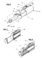
- Fig. 6 shows a second embodiment of an inventive discharge device 40 in a perspective view. Those features which correspond to the first embodiment are provided with the same reference numerals. Furthermore, a double syringe 50 is shown, which is suitable for use with the discharge device 1, 40.
- This variant corresponds essentially to the first embodiment, the main difference being a simplified locking and unlocking mechanism, and the discharge operation can not be interrupted.
- the device 40 comprises a resilient finger rest 36, whose rear end 36b is rigidly fixed to the handling part 5 in the region of the rear end 5b and continues forward along the cylindrical surface 18 as far as the front end 5a of the handling part 5.
- a locking tooth 37 is arranged at the front end 36a of the finger rest 36.
- the finger rest with locking tooth essentially assumes the task of the locking sleeve 6 in the first embodiment 1 of the discharge device.
- the locking tooth 37 is directed in contrast to the first embodiment to the outside.
- the locking tooth 37 is provided with a corresponding locking groove 41 on the discharge piston 2.
- the discharge piston 2 has at the front end a receiving slot 10, in which the finger rest 7 can be inserted.
- the finger rest has an arresting support 42 which extends in the shape of a umbrella over the hollow cylinder 8 of the discharge piston 2.
- the locking groove 41 is formed, see Fig. 7 ,
- FIGS. 7 and 8 show a perspective sectional view of the guide part 2 according to the sectional planes VII-VII and VIII-VIII in Fig. 6 in the tense and triggered position.
- a locking toothing is also conceivable for external locking means according to the second embodiment.
- a fixation of the discharge piston in a locking means at any time of dispensing is possible by simply canceling the manual pressure.
- locking conceivable which include a locking tooth on the discharge piston 2 and a locking toothing on the handling part 5. It is also conceivable to provide an external locking means by a locking tooth on a locking sleeve or an internal locking means via a locking clip on the handling part.
- a pressure medium instead of a compression spring, a compressed air cartridge or the like pressure medium can be used to facilitate the self-discharge.
Landscapes
- Health & Medical Sciences (AREA)
- Engineering & Computer Science (AREA)
- Heart & Thoracic Surgery (AREA)
- Vascular Medicine (AREA)
- Anesthesiology (AREA)
- Biomedical Technology (AREA)
- Mechanical Engineering (AREA)
- Hematology (AREA)
- Life Sciences & Earth Sciences (AREA)
- Animal Behavior & Ethology (AREA)
- General Health & Medical Sciences (AREA)
- Public Health (AREA)
- Veterinary Medicine (AREA)
- Infusion, Injection, And Reservoir Apparatuses (AREA)
Abstract
Description
Die Erfindung betrifft eine Vorrichtung mit einem mit einem Druckmedium beaufschlagbaren Austragkolben zum Austragen einer Spritze gemäss Oberbegriff von Patentanspruch 1.The invention relates to a device having a delivery piston which can be acted upon by a pressure medium for discharging a syringe according to the preamble of
Eine solche Austragspritze mit Injektionsnadel ist aus der
Bei der Wundversorgung finden neben herkömmlichen Verbandmaterialien zur keimfreien Wundabdeckung auch Flüssigkeiten, Pasten und Gelatine Verwendung, welche in Kombination mit anderen Stoffen für eine Wundversiegelung, Wundheilung und Schmerzbekämpfung sorgen. Dabei kommen in zunehmendem Masse Mehrkomponenten-Stoffe zum Einsatz, bei welchen jedoch vor dem Auftragen auf die Wunde ein Zusammenbringen und Vermischen erforderlich ist. Hierzu werden die Komponenten beispielsweise in einer Doppelspritze gelagert und vor der Applikation auf die Haut- oder Wundoberfläche mit Hilfe eines statischen Mischers oder Sprühsystems gemischt. Das Austragen des Gemisches erfolgt durch eine manuelle Druckeinwirkung auf den Stössel der Doppelspritze.In wound care, in addition to conventional dressings for germ-free wound cover, liquids, pastes and gelatine are also used which, in combination with other substances, provide wound sealing, wound healing and pain relief. In the process, multicomponent substances are increasingly used, but in which case they are applied to the wound before application Matching and mixing is required. For this purpose, the components are stored, for example, in a double syringe and mixed before application to the skin or wound surface using a static mixer or spray system. The discharge of the mixture is carried out by a manual pressure on the plunger of the double syringe.
Insbesondere bei Langzeitpatienten oder bei chronischen Wunden ist eine selbstständige Wundversorgung vom Patienten nicht nur wünschenswert sondern auch kostendämpfend. Jedoch erfordert der Austragvorgang bei einer herkömmlichen Doppelspritze in nicht zu unterschätzendem Masse eine Kraft und eine gewisse manuelle Geschicklichkeit seitens des Patienten. Je nach Stelle der Wunde kann das Bedienen der Doppelspritze durch den Patienten Schwierigkeiten bereiten.Especially in long-term patients or chronic wounds, independent wound care from the patient is not only desirable but also cost-cutting. However, in a conventional double syringe, the discharge process requires considerable force and manual dexterity on the part of the patient to an extent that should not be underestimated. Depending on the site of the wound, it may be difficult for the patient to operate the double syringe.
Auch ist eine Dosiermöglichkeit der auszutragenden Komponenten wünschenswert, welche durch herkömmliche Doppelspritzen nur unzureichend gewährleistet ist.Also, a metering possibility of the components to be discharged is desirable, which is only insufficiently ensured by conventional double syringes.
Hiervon ausgehend liegt der Erfindung die Aufgabe zugrunde, eine Vorrichtung der eingangs genannten Art derart weiterzubilden, dass sie eine Verwendung von Mehrfachspritzen erlaubt und kostengünstig herstellbar ist und eine verbesserte Handhabbarkeit für Patienten gewährleistet.On this basis, the invention has the object, a device of the type mentioned in such a way that it allows the use of multiple syringes and is inexpensive to produce and ensures improved handling for patients.
Es ist eine weitere Aufgabe der Erfindung, eine wiederholte Verwendung und ein genaues Dosieren beliebiger Austragmengen der Vorrichtung zu ermöglichen.It is a further object of the invention to enable repeated use and accurate metering of any dispensing rates of the device.
Diese Aufgaben werden durch eine Vorrichtung gemäss dem unabhängigen Patentanspruch 1 gelöst. Weitere bevorzugte Ausführungsformen der Erfindung sind in den abhängigen Patentansprüchen definiert.These objects are achieved by a device according to
Nachfolgend wird die Erfindung anhand von Zeichnungen von Ausführungsbeispielen näher erläutert. Dabei zeigen:
- Fig. 1
- eine Explosionsdarstellung eines ersten Ausführungsbeispiels einer erfindungsgemässen Vorrichtung zum automatisierten Austragen einer Doppelspritze;
- Fig. 1d
- eine perspektivische Ansicht der zusammengebauten Vorrichtung gemäss
Fig. 1 , - Fig. 1a
- eine perspektivische Ansicht des Handhabungsteils der in
Fig. 1 gezeigten Vorrichtung, - Fig. 1b
- eine perspektivische Ansicht der Arretierhülse der in
Fig. 1 gezeigten Vorrichtung, - Fig. 1c
- eine andere perspektivische Ansicht der Arretierhülse von
Fig. 1b , - Fig. 2:
- eine perspektivische Ansicht eines Teils der in
Fig. 1 gezeigten Vorrichtung mit dem Austragkolben in gespannter Position - Fig. 3
- eine perspektivische Ansicht des Austragkolbens von
Fig. 1 , - Fig. 4:
- eine teilweise Schnittansicht gemäss der Ebene IV-IV in
Fig. 2 , in welcher die Arretierstellung des Austragkolbens in der gespannten Kolbenposition dargestellt ist; - Fig. 5:
- eine teilweise Schnittansicht gemäss der Ebene V-V in
Fig. 2 , in welcher die gelöste Stellung der Arretierhülse dargestellt ist; - Fig. 6:
- eine perspektivische Ansicht eines zweiten Ausführungsbeispiels einer erfindungsgemässen Vorrichtung mit einer Doppelspritze zum automatisierten Austragen,
- Fig. 7:
- einen Schnitt gemäss der Ebene VII-VII in
Fig. 6 in einer gespannten Stellung des Austragkolbens, und - Fig. 8:
- einen Schnitt gemäss der Ebene VIII-VIII in
Fig. 6 in einer entspannten Stellung des Austragkolbens.
- Fig. 1
- an exploded view of a first embodiment of an inventive device for automatically discharging a double syringe;
- Fig. 1d
- a perspective view of the assembled device according to
Fig. 1 . - Fig. 1a
- a perspective view of the handling part of in
Fig. 1 shown device, - Fig. 1b
- a perspective view of the locking sleeve of in
Fig. 1 shown device, - Fig. 1c
- another perspective view of the locking sleeve of
Fig. 1b . - Fig. 2:
- a perspective view of a part of in
Fig. 1 shown device with the discharge piston in the cocked position - Fig. 3
- a perspective view of the discharge of
Fig. 1 . - 4:
- a partial sectional view according to the plane IV-IV in
Fig. 2 in which the locking position of the discharge piston is shown in the cocked piston position; - Fig. 5:
- a partial sectional view according to the plane VV in
Fig. 2 in which the released position of the locking sleeve is shown; - Fig. 6:
- a perspective view of a second embodiment of an inventive device with a double syringe for automated dispensing,
- Fig. 7:
- a section according to the level VII-VII in
Fig. 6 in a cocked position of the discharge piston, and - Fig. 8:
- a section according to the plane VIII-VIII in
Fig. 6 in a relaxed position of the discharge piston.
Im folgenden werden bei den Ausführungsbeispielen Doppelspritzen dargestellt und beschrieben, doch kann es sich auch um Mehrfachspritzen oder Mehrfachkartuschen mit mehr als zwei Vorratsbehältern handeln, wobei dann der Austragkolben hierfür angepasst ist. Die Begriffe "vorne" und "hinten" beziehen sich auf den Spritzenauslass, der vorne ist.In the following double syringes are shown and described in the embodiments, but it may also be multiple or multiple cartridges with more than two reservoirs, in which case the discharge is adapted for this purpose. The terms "front" and "rear" refer to the syringe outlet that is in front.
Der Austragkolben 2 gemäss den
Wie aus
Die Kolbenbewegung innerhalb des Führungsteils 3 ist durch einen Aufnahmeflansch für Spritze 15 am vorderen Ende 3a des Führungsteils 3 begrenzt. Dieser Aufnahmeflansch für Spritze 15 ist als Querwand ausgebildet, die sich beidseitig über den Zylinderdurchmesser hinaus erstreckt und in ihrem Mittelbereich eine U-förmige Ausnahme aufweist, durch welche eine Doppelspritze 50 und deren Doppelstössel 55 führbar ist. Entlang der Oberkante des Aufnahmeflansches 15 ist eine Einstecköffnung 16 für den Spritzenflansch einer Doppelspritze vorhanden, wie aus
Das Federelement 4 ist durch eine zylindrisch gewickelte Druckfeder gebildet, deren vorderes Ende 4a derart im Innenraum des Hohlzylinders 8 angeordnet ist, dass ihr hinteres Ende 4b aus dem offenen hinteren Ende 2b des Austragkolbens 2 hinausragt.The
In
Gemäss
Durch den stufenförmigen Anschlagbund 20 ist ein vorderer Aufnahmebereich 33 des Handhabungsteils 5 definiert, welcher zur Aufnahme des hinteren Endabschnitts 3c des Führungsteils 3 ausgebildet ist, so dass dessen hinteres Ende 3b an den stufenförmigen Anschlagbund 20 anschliesst. An zwei gegenüberliegenden Seiten der Innenwandung des Aufnahmebereichs 33 befindet sich jeweils ein Positioniernocken 21a, b, welche sich ausgehend von den stufenförmigen Anschlagbund 20 in vorderer Richtung erstrecken.By the stepped
Demgemäss sind im hinteren Endabschnitt 3c des Führungsteils 3 zwei entsprechende Positionierschlitze 22a, b vorhanden, wodurch beim Einschieben des Führungsteils 3 in das Handhabungsteil 5 dessen korrekte Orientierung sichergestellt wird. An zwei gegenüberliegenden Seiten auf der Oberfläche des hinteren Endabschnitts 3c des Führungsteils 3 ist jeweils eine Schnappnase 23a, b angeordnet. Entsprechende Schnapprillen 24a, b sind entlang der Innenwandung des Aufnahmebereichs 33 vorhanden. Dadurch wird beim Zusammenfügen der Bauteile 3, 5 eine unlösbare Schnappverbindung zwischen den Schnappnasen 23a, b und den Schnapprillen 24a, b verwirklicht.Accordingly, in the
Eine zylindrische Federführung 25 ist im Zentralbereich des hohlförmigen Innenraums des Handhabungsteils 5 angeordnet und erstreckt sich in axialer Richtung im Wesentlichen über dessen Gesamtlänge, wobei sie innenseitig in die Endwand 19 mündet. Dabei entspricht der Aussendurchmesser der zylindrischen Federführung 25 im Wesentlichen dem Innendurchmesser des Federelements 4. Dadurch ist das hintere Ende 4b des Federelements 4 über die zylindrische Federführung 25 an die Innenseite der Endwand 19 führbar, wodurch beim Zusammenfügen der Bauteile 2, 3, 4 und 5 das Federelement 4 zusammengedrückt wird.A
Eine hintere Anschlagschulter 26 ist entlang der zylindrischen Oberfläche 18 umfänglich auskragend hinter dem Aufnahmebereich 33 angeordnet. Dabei befindet sich die Anschlagschulter am vorderen Ende des Endabschnitts 5c des Handhabungsteils 5.A
Gemäss den
Entlang der Innenwandung des Hülsenmantels 27 ist ein Arretierzahn 30 angeordnet, der sich radial nach innen erstreckt. Einem dem Arretierzahn 30 entsprechende seitliche Durchgangsöffnung 32 ist im vorderen Endabschnitt 5c des Handhabungsteils 5 vorgesehen. Infolge der elliptischen Form der Innenabmessung der Arretierhülse und der zylindrischen Oberfläche 5c ist ein Heranführen des Arretierzahns 30 an die seitliche Durchgangsöffnung 32 beim Zusammenfügen der Bauteile 5, 6 und ein anschliessendes Einführen des Arretierzahns 30 in die seitliche Durchgangsöffnung 32 ermöglicht, so dass der Arretierzahn 30 in den hohlförmigen Innenraum des Handhabungsteils 5 hineinragt.Along the inner wall of the
Gemäss
In
In der in
Beim Aufheben der manuellen Druckeinwirkung auf die Fingerauflage 29 wird die Arretierhülse 6 durch die Federwirkung des Druckelements 31 in die in
Eine manuelle Rückführung des Austragkolbens 2 nach hinten ist aus jeder Kolbenposition möglich, indem Druck auf die Fingerauflagefläche 11 der Fingerauflage 7 ausgeübt wird, denn die keilförmige Ausbildung des Arretierzahns 30 bzw. der Arretierverzahnung 35 erlaubt ein Loslösen des Arretierzahns 30 nach hinten aus einer Verzahnungslücke.A manual return of the
Diese Variante entspricht im Wesentlichen dem ersten Ausführungsbeispiel, wobei der Hauptunterschied in einem vereinfachten Arretier- und Aulösemechanismus besteht und der Austragvorgang nicht unterbrochen werden kann.This variant corresponds essentially to the first embodiment, the main difference being a simplified locking and unlocking mechanism, and the discharge operation can not be interrupted.
Die Vorrichtung 40 umfasst eine federnde Fingerauflage 36, deren hinteres Ende 36b am Handhabungsteil 5 im Bereich des hinteren Endes 5b starr befestigt ist und sich nach vorne entlang der zylindrischen Oberfläche 18 bis hin zum vorderen Ende 5a des Handhabungsteils 5 fortsetzt. Am vorderen Ende 36a der Fingerauflage 36 ist ein Arretierzahn 37 angeordnet. Dabei übernimmt die Fingerauflage mit Arretierzahn im Wesentlichen die Aufgabe der Arretierhülse 6 in der ersten Ausführungsform 1 der Austragvorrichtung. In dieser Ausführung ist der Arretierzahn 37 im Gegensatz zum ersten Ausführungsbeispiel nach aussen gerichtet.The
Dem Arretierzahn 37 ist eine entsprechende Arretiernut 41 am Austragkolben 2 vorgesehen. Der Austragkolben 2 weist am vorderen Ende einen Aufnahmeschlitz 10 auf, in welchem die Fingerauflage 7 steckbar ist. Die Fingerauflage weist einen Arretiersupport 42 auf, der schirmförmig über dem Hohlzylinder 8 des Austragkolbens 2 verläuft. Auf der Unterseite von Arretiersupport 42 ist die Arretiernut 41 ausgebildet, siehe
Bei Druckeinwirkung auf die Druckfläche 38 der Fingerauflage 36 wird der Arretierzahn 37 hinuntergedrückt und rastet aus der Arretiernut 41 aus. Durch die als Federarm ausgebildeten Fingerauflage 36 wird der Arretierzahn 37 nach Aufheben der manuellen Druckeinwirkung in seine Ursprungsposition zurückgeführt, wobei durch die Keilform des Arretierzahns 37 bei einer Wiederverwendung des Gerätes zu einem späteren Zeitpunkt ein erneutes Einrasten in der hinteren Position gewährleistet ist.Upon pressure on the
Die
Aus der Beschreibung der Ausführungsbeispiele sind dem Fachmann zahlreiche Abwandlungen zugänglich, ohne den Schutzbereich der Erfindung zu verlassen, der durch die Ansprüche definiert ist. So ist auch bei externen Arretiermitteln gemäss dem zweiten Ausführungsbeispiel eine Arretierverzahnung denkbar. Dadurch ist durch einfaches Aufheben der manuellen Druckeinwirkung eine Fixierung des Austragkolbens in einem Arretiermittel zu jedem Zeitpunkt des Austragens möglich. Weiterhin sind auch Arretiermittel denkbar, die einen Arretierzahn am Austragkolben 2 und eine Arretierverzahnung am Handhabungsteil 5 umfassen. Ferner ist denkbar, ein externes Arretiermittel durch einen Arretierzahn an einer Arretierhülse oder ein internes Arretiermittel über einen Arretierbügel am Handhabungsteil vorzusehen.Numerous modifications will become apparent to those skilled in the art from the description of the embodiments without departing from the scope of the invention, which is defined by the claims. Thus, a locking toothing is also conceivable for external locking means according to the second embodiment. As a result, a fixation of the discharge piston in a locking means at any time of dispensing is possible by simply canceling the manual pressure. Furthermore, are also locking conceivable, which include a locking tooth on the
Ausserdem kann als Druckmedium anstatt einer Druckfeder eine Druckluftpatrone oder dergleichen Druckmedium verwendet werden, um das Selbst-Austragen zu erleichtern.In addition, as a pressure medium instead of a compression spring, a compressed air cartridge or the like pressure medium can be used to facilitate the self-discharge.
Claims (12)
Applications Claiming Priority (1)
| Application Number | Priority Date | Filing Date | Title |
|---|---|---|---|
| CH1242008 | 2008-01-29 |
Publications (2)
| Publication Number | Publication Date |
|---|---|
| EP2085147A1 true EP2085147A1 (en) | 2009-08-05 |
| EP2085147B1 EP2085147B1 (en) | 2012-04-04 |
Family
ID=39322617
Family Applications (1)
| Application Number | Title | Priority Date | Filing Date |
|---|---|---|---|
| EP09405004A Not-in-force EP2085147B1 (en) | 2008-01-29 | 2009-01-12 | Device with pressure charged piston for dispensing a multiple syringe or multiple cartridge |
Country Status (3)
| Country | Link |
|---|---|
| US (1) | US8038651B2 (en) |
| EP (1) | EP2085147B1 (en) |
| JP (1) | JP2009178554A (en) |
Families Citing this family (10)
| Publication number | Priority date | Publication date | Assignee | Title |
|---|---|---|---|---|
| GB2486693B (en) * | 2010-12-22 | 2016-05-18 | Owen Mumford Ltd | Autoinjectors and manufacturing systems thereof |
| WO2014086635A1 (en) * | 2012-12-03 | 2014-06-12 | Sulzer Mixpac Ag | Discharging device |
| US9199033B1 (en) | 2014-10-28 | 2015-12-01 | Bayer Healthcare Llc | Self-orienting syringe and syringe interface |
| EP3212256A4 (en) | 2014-10-28 | 2018-07-18 | Bayer HealthCare LLC | Self-orienting pressure jacket and pressure jacket-to-injector interface |
| BR112017008878B1 (en) | 2014-10-28 | 2022-10-11 | Bayer Healthcare Llc | PRESSURE SHIRT |
| NO2689315T3 (en) | 2014-10-28 | 2018-04-14 | ||
| CN108472433B (en) | 2015-11-13 | 2021-12-14 | 拜耳医药保健有限公司 | Nested syringe assembly |
| US10231846B2 (en) | 2016-08-19 | 2019-03-19 | Stryker European Holdings I, Llc | Bone graft delivery loading assembly |
| US11191893B2 (en) | 2018-01-31 | 2021-12-07 | Bayer Healthcare Llc | System and method for syringe engagement with injector |
| WO2019188853A1 (en) | 2018-03-28 | 2019-10-03 | テルモ株式会社 | Gasket pressing tool and liquid medicine administration tool using same |
Citations (8)
| Publication number | Priority date | Publication date | Assignee | Title |
|---|---|---|---|---|
| US2565081A (en) | 1948-09-15 | 1951-08-21 | Emma C Maynes | Device for operating hypodermic syringes |
| DE1957833A1 (en) * | 1968-11-21 | 1970-07-02 | Maurice Steiner | Injection syringe, especially injection syringe handled by the patient himself |
| US3702608A (en) | 1970-12-15 | 1972-11-14 | Robert C Tibbs | Painless injection device with powered plunger |
| WO1995003844A1 (en) * | 1993-07-31 | 1995-02-09 | Weston Medical Limited | Needle-less injector |
| WO1999037343A1 (en) | 1998-01-24 | 1999-07-29 | Medico Development Investment Company | Injection device |
| DE20006986U1 (en) * | 1999-11-16 | 2000-07-20 | Roesch Ag Medizintechnik | Injection device |
| US6228067B1 (en) * | 1997-03-03 | 2001-05-08 | B D MEDICO S.à.R.L. | Injection device |
| DE102005048871A1 (en) * | 2005-10-12 | 2007-04-19 | Böhner, Andreas | Device for appropriate emptying of medicinal ampoules e.g. for needleless injection under skin, has locking pin and releasing of size cylinder takes place through broadening which unlock locking device after putting ampoules on skin |
Family Cites Families (3)
| Publication number | Priority date | Publication date | Assignee | Title |
|---|---|---|---|---|
| US5584815A (en) * | 1993-04-02 | 1996-12-17 | Eli Lilly And Company | Multi-cartridge medication injection device |
| US5722956A (en) * | 1995-08-24 | 1998-03-03 | The General Hospital Corporation | Multi-dose syringe driver |
| US6802822B1 (en) * | 2000-03-31 | 2004-10-12 | 3M Innovative Properties Company | Dispenser for an adhesive tissue sealant having a flexible link |
-
2009
- 2009-01-12 EP EP09405004A patent/EP2085147B1/en not_active Not-in-force
- 2009-01-23 US US12/320,343 patent/US8038651B2/en not_active Expired - Fee Related
- 2009-01-28 JP JP2009016454A patent/JP2009178554A/en active Pending
Patent Citations (8)
| Publication number | Priority date | Publication date | Assignee | Title |
|---|---|---|---|---|
| US2565081A (en) | 1948-09-15 | 1951-08-21 | Emma C Maynes | Device for operating hypodermic syringes |
| DE1957833A1 (en) * | 1968-11-21 | 1970-07-02 | Maurice Steiner | Injection syringe, especially injection syringe handled by the patient himself |
| US3702608A (en) | 1970-12-15 | 1972-11-14 | Robert C Tibbs | Painless injection device with powered plunger |
| WO1995003844A1 (en) * | 1993-07-31 | 1995-02-09 | Weston Medical Limited | Needle-less injector |
| US6228067B1 (en) * | 1997-03-03 | 2001-05-08 | B D MEDICO S.à.R.L. | Injection device |
| WO1999037343A1 (en) | 1998-01-24 | 1999-07-29 | Medico Development Investment Company | Injection device |
| DE20006986U1 (en) * | 1999-11-16 | 2000-07-20 | Roesch Ag Medizintechnik | Injection device |
| DE102005048871A1 (en) * | 2005-10-12 | 2007-04-19 | Böhner, Andreas | Device for appropriate emptying of medicinal ampoules e.g. for needleless injection under skin, has locking pin and releasing of size cylinder takes place through broadening which unlock locking device after putting ampoules on skin |
Also Published As
| Publication number | Publication date |
|---|---|
| JP2009178554A (en) | 2009-08-13 |
| EP2085147B1 (en) | 2012-04-04 |
| US20090192460A1 (en) | 2009-07-30 |
| US8038651B2 (en) | 2011-10-18 |
Similar Documents
| Publication | Publication Date | Title |
|---|---|---|
| EP2085147B1 (en) | Device with pressure charged piston for dispensing a multiple syringe or multiple cartridge | |
| EP2323717B1 (en) | Automatic injection device for administering a fixed dose | |
| EP1084763B1 (en) | Dispenser for dispensing, in particular spraying, a fluid from a container | |
| EP1737393B1 (en) | Device for inserting deformable intraocular lenses | |
| EP0581788B1 (en) | Injection device | |
| DE69822160T2 (en) | IMPROVED INJECTION SYRINGE | |
| EP2148710B1 (en) | Injection device for delivering a medication | |
| EP2252351B1 (en) | Administering apparatus comprising a holding device | |
| EP1447140B1 (en) | Discharging device for manually producing a given volume flow | |
| DE10323603A1 (en) | Dosing device with a pump device | |
| DE102004042581A1 (en) | Car pen for two-chamber ampoule | |
| DE10207276A1 (en) | Needle insertion device with a transversely movable holding element | |
| DE202011109359U1 (en) | Automatic hypodermic syringe | |
| EP1767233A1 (en) | Syringe adapter for a medical injector | |
| DE102008037686B4 (en) | Container and piston rod assembly and their use | |
| EP3102257B1 (en) | Injection device | |
| WO2004006997A1 (en) | Administration device comprising a plunger rod with a return lock | |
| DE102006005784B4 (en) | Injection | |
| WO1996003170A1 (en) | Device for advancing a piston-moving element | |
| DE102012107747B4 (en) | Lancing device for obtaining body fluid samples | |
| DE102006000929B4 (en) | Injector for intraocular lenses | |
| EP0701864A2 (en) | Applicator | |
| DE4018008A1 (en) | GUIDE AND MOUNTING UNIT FOR A COMPRESSION SPRING | |
| EP2442916A1 (en) | Multicomponent cartridge for single use | |
| DE202004016787U1 (en) | Automatic injection unit comprises a release element which is joined to the trigger element so that it moves longitudinally together with the trigger element, and is laterally movable relative to it |
Legal Events
| Date | Code | Title | Description |
|---|---|---|---|
| PUAI | Public reference made under article 153(3) epc to a published international application that has entered the european phase |
Free format text: ORIGINAL CODE: 0009012 |
|
| AK | Designated contracting states |
Kind code of ref document: A1 Designated state(s): AT BE BG CH CY CZ DE DK EE ES FI FR GB GR HR HU IE IS IT LI LT LU LV MC MK MT NL NO PL PT RO SE SI SK TR |
|
| AX | Request for extension of the european patent |
Extension state: AL BA RS |
|
| 17P | Request for examination filed |
Effective date: 20100209 |
|
| 17Q | First examination report despatched |
Effective date: 20100312 |
|
| AKX | Designation fees paid |
Designated state(s): CH DE FR GB LI |
|
| REG | Reference to a national code |
Ref country code: DE Ref legal event code: R079 Ref document number: 502009003191 Country of ref document: DE Free format text: PREVIOUS MAIN CLASS: B05C0017010000 Ipc: A61M0005145000 |
|
| GRAP | Despatch of communication of intention to grant a patent |
Free format text: ORIGINAL CODE: EPIDOSNIGR1 |
|
| RIC1 | Information provided on ipc code assigned before grant |
Ipc: A61M 5/20 20060101ALI20110906BHEP Ipc: B05C 17/01 20060101ALI20110906BHEP Ipc: A61M 5/145 20060101AFI20110906BHEP |
|
| GRAS | Grant fee paid |
Free format text: ORIGINAL CODE: EPIDOSNIGR3 |
|
| GRAA | (expected) grant |
Free format text: ORIGINAL CODE: 0009210 |
|
| AK | Designated contracting states |
Kind code of ref document: B1 Designated state(s): CH DE FR GB LI |
|
| REG | Reference to a national code |
Ref country code: GB Ref legal event code: FG4D Free format text: NOT ENGLISH |
|
| REG | Reference to a national code |
Ref country code: CH Ref legal event code: NV Representative=s name: ISLER & PEDRAZZINI AG Ref country code: CH Ref legal event code: EP |
|
| REG | Reference to a national code |
Ref country code: DE Ref legal event code: R096 Ref document number: 502009003191 Country of ref document: DE Effective date: 20120531 |
|
| PLBE | No opposition filed within time limit |
Free format text: ORIGINAL CODE: 0009261 |
|
| STAA | Information on the status of an ep patent application or granted ep patent |
Free format text: STATUS: NO OPPOSITION FILED WITHIN TIME LIMIT |
|
| 26N | No opposition filed |
Effective date: 20130107 |
|
| REG | Reference to a national code |
Ref country code: DE Ref legal event code: R097 Ref document number: 502009003191 Country of ref document: DE Effective date: 20130107 |
|
| REG | Reference to a national code |
Ref country code: FR Ref legal event code: PLFP Year of fee payment: 7 |
|
| REG | Reference to a national code |
Ref country code: DE Ref legal event code: R082 Ref document number: 502009003191 Country of ref document: DE Representative=s name: MANITZ FINSTERWALD PATENTANWAELTE PARTMBB, DE Ref country code: DE Ref legal event code: R082 Ref document number: 502009003191 Country of ref document: DE Representative=s name: MANITZ, FINSTERWALD & PARTNER GBR, DE Ref country code: DE Ref legal event code: R082 Ref document number: 502009003191 Country of ref document: DE Representative=s name: HOEGER, STELLRECHT & PARTNER PATENTANWAELTE MB, DE |
|
| REG | Reference to a national code |
Ref country code: FR Ref legal event code: PLFP Year of fee payment: 8 |
|
| REG | Reference to a national code |
Ref country code: DE Ref legal event code: R082 Ref document number: 502009003191 Country of ref document: DE Representative=s name: MANITZ FINSTERWALD PATENT- UND RECHTSANWALTSPA, DE Ref country code: DE Ref legal event code: R082 Ref document number: 502009003191 Country of ref document: DE Representative=s name: MANITZ FINSTERWALD PATENTANWAELTE PARTMBB, DE Ref country code: DE Ref legal event code: R082 Ref document number: 502009003191 Country of ref document: DE Representative=s name: MANITZ, FINSTERWALD & PARTNER GBR, DE Ref country code: DE Ref legal event code: R081 Ref document number: 502009003191 Country of ref document: DE Owner name: SULZER MIXPAC AG, CH Free format text: FORMER OWNER: MEDMIX SYSTEMS AG, ROTKREUZ, CH |
|
| REG | Reference to a national code |
Ref country code: CH Ref legal event code: PUE Owner name: SULZER MIXPAC AG, CH Free format text: FORMER OWNER: MEDMIX SYSTEMS AG, CH |
|
| REG | Reference to a national code |
Ref country code: GB Ref legal event code: 732E Free format text: REGISTERED BETWEEN 20160310 AND 20160316 |
|
| REG | Reference to a national code |
Ref country code: FR Ref legal event code: TP Owner name: SULZER MIXPAC AG, CH Effective date: 20160425 |
|
| REG | Reference to a national code |
Ref country code: FR Ref legal event code: PLFP Year of fee payment: 9 |
|
| REG | Reference to a national code |
Ref country code: FR Ref legal event code: PLFP Year of fee payment: 10 |
|
| PGFP | Annual fee paid to national office [announced via postgrant information from national office to epo] |
Ref country code: CH Payment date: 20180119 Year of fee payment: 10 Ref country code: GB Payment date: 20180119 Year of fee payment: 10 |
|
| PGFP | Annual fee paid to national office [announced via postgrant information from national office to epo] |
Ref country code: FR Payment date: 20180119 Year of fee payment: 10 |
|
| REG | Reference to a national code |
Ref country code: CH Ref legal event code: PL |
|
| GBPC | Gb: european patent ceased through non-payment of renewal fee |
Effective date: 20190112 |
|
| PG25 | Lapsed in a contracting state [announced via postgrant information from national office to epo] |
Ref country code: FR Free format text: LAPSE BECAUSE OF NON-PAYMENT OF DUE FEES Effective date: 20190131 |
|
| PG25 | Lapsed in a contracting state [announced via postgrant information from national office to epo] |
Ref country code: GB Free format text: LAPSE BECAUSE OF NON-PAYMENT OF DUE FEES Effective date: 20190112 Ref country code: CH Free format text: LAPSE BECAUSE OF NON-PAYMENT OF DUE FEES Effective date: 20190131 Ref country code: LI Free format text: LAPSE BECAUSE OF NON-PAYMENT OF DUE FEES Effective date: 20190131 |
|
| PGFP | Annual fee paid to national office [announced via postgrant information from national office to epo] |
Ref country code: DE Payment date: 20200121 Year of fee payment: 12 |
|
| REG | Reference to a national code |
Ref country code: DE Ref legal event code: R119 Ref document number: 502009003191 Country of ref document: DE |
|
| PG25 | Lapsed in a contracting state [announced via postgrant information from national office to epo] |
Ref country code: DE Free format text: LAPSE BECAUSE OF NON-PAYMENT OF DUE FEES Effective date: 20210803 |