EP2079397B1 - Stent member - Google Patents
Stent member Download PDFInfo
- Publication number
- EP2079397B1 EP2079397B1 EP07852901A EP07852901A EP2079397B1 EP 2079397 B1 EP2079397 B1 EP 2079397B1 EP 07852901 A EP07852901 A EP 07852901A EP 07852901 A EP07852901 A EP 07852901A EP 2079397 B1 EP2079397 B1 EP 2079397B1
- Authority
- EP
- European Patent Office
- Prior art keywords
- stent
- tubular body
- stents
- graft
- elements
- Prior art date
- Legal status (The legal status is an assumption and is not a legal conclusion. Google has not performed a legal analysis and makes no representation as to the accuracy of the status listed.)
- Active
Links
- 239000000463 material Substances 0.000 claims abstract description 29
- 238000000034 method Methods 0.000 claims description 10
- 210000000115 thoracic cavity Anatomy 0.000 description 12
- 210000000709 aorta Anatomy 0.000 description 11
- 239000003550 marker Substances 0.000 description 11
- 210000002376 aorta thoracic Anatomy 0.000 description 6
- 230000000717 retained effect Effects 0.000 description 5
- 241001465754 Metazoa Species 0.000 description 4
- 210000005166 vasculature Anatomy 0.000 description 3
- 210000001765 aortic valve Anatomy 0.000 description 2
- 230000017531 blood circulation Effects 0.000 description 2
- 210000004204 blood vessel Anatomy 0.000 description 2
- 230000014759 maintenance of location Effects 0.000 description 2
- 230000008569 process Effects 0.000 description 2
- 238000009958 sewing Methods 0.000 description 2
- 229910001220 stainless steel Inorganic materials 0.000 description 2
- 239000010935 stainless steel Substances 0.000 description 2
- 230000009471 action Effects 0.000 description 1
- 238000012282 endovascular technique Methods 0.000 description 1
- 210000001105 femoral artery Anatomy 0.000 description 1
- 238000003780 insertion Methods 0.000 description 1
- 230000037431 insertion Effects 0.000 description 1
- 230000005012 migration Effects 0.000 description 1
- 238000013508 migration Methods 0.000 description 1
- 238000012986 modification Methods 0.000 description 1
- 230000004048 modification Effects 0.000 description 1
- 229910001000 nickel titanium Inorganic materials 0.000 description 1
- 230000008439 repair process Effects 0.000 description 1
Images


Classifications
-
- A—HUMAN NECESSITIES
- A61—MEDICAL OR VETERINARY SCIENCE; HYGIENE
- A61F—FILTERS IMPLANTABLE INTO BLOOD VESSELS; PROSTHESES; DEVICES PROVIDING PATENCY TO, OR PREVENTING COLLAPSING OF, TUBULAR STRUCTURES OF THE BODY, e.g. STENTS; ORTHOPAEDIC, NURSING OR CONTRACEPTIVE DEVICES; FOMENTATION; TREATMENT OR PROTECTION OF EYES OR EARS; BANDAGES, DRESSINGS OR ABSORBENT PADS; FIRST-AID KITS
- A61F2/00—Filters implantable into blood vessels; Prostheses, i.e. artificial substitutes or replacements for parts of the body; Appliances for connecting them with the body; Devices providing patency to, or preventing collapsing of, tubular structures of the body, e.g. stents
- A61F2/02—Prostheses implantable into the body
- A61F2/04—Hollow or tubular parts of organs, e.g. bladders, tracheae, bronchi or bile ducts
- A61F2/06—Blood vessels
- A61F2/07—Stent-grafts
-
- A—HUMAN NECESSITIES
- A61—MEDICAL OR VETERINARY SCIENCE; HYGIENE
- A61F—FILTERS IMPLANTABLE INTO BLOOD VESSELS; PROSTHESES; DEVICES PROVIDING PATENCY TO, OR PREVENTING COLLAPSING OF, TUBULAR STRUCTURES OF THE BODY, e.g. STENTS; ORTHOPAEDIC, NURSING OR CONTRACEPTIVE DEVICES; FOMENTATION; TREATMENT OR PROTECTION OF EYES OR EARS; BANDAGES, DRESSINGS OR ABSORBENT PADS; FIRST-AID KITS
- A61F2/00—Filters implantable into blood vessels; Prostheses, i.e. artificial substitutes or replacements for parts of the body; Appliances for connecting them with the body; Devices providing patency to, or preventing collapsing of, tubular structures of the body, e.g. stents
- A61F2/82—Devices providing patency to, or preventing collapsing of, tubular structures of the body, e.g. stents
- A61F2/86—Stents in a form characterised by the wire-like elements; Stents in the form characterised by a net-like or mesh-like structure
- A61F2/88—Stents in a form characterised by the wire-like elements; Stents in the form characterised by a net-like or mesh-like structure the wire-like elements formed as helical or spiral coils
- A61F2/885—Stents in a form characterised by the wire-like elements; Stents in the form characterised by a net-like or mesh-like structure the wire-like elements formed as helical or spiral coils comprising a coil including a plurality of spiral or helical sections with alternate directions around a central axis
-
- A—HUMAN NECESSITIES
- A61—MEDICAL OR VETERINARY SCIENCE; HYGIENE
- A61F—FILTERS IMPLANTABLE INTO BLOOD VESSELS; PROSTHESES; DEVICES PROVIDING PATENCY TO, OR PREVENTING COLLAPSING OF, TUBULAR STRUCTURES OF THE BODY, e.g. STENTS; ORTHOPAEDIC, NURSING OR CONTRACEPTIVE DEVICES; FOMENTATION; TREATMENT OR PROTECTION OF EYES OR EARS; BANDAGES, DRESSINGS OR ABSORBENT PADS; FIRST-AID KITS
- A61F2/00—Filters implantable into blood vessels; Prostheses, i.e. artificial substitutes or replacements for parts of the body; Appliances for connecting them with the body; Devices providing patency to, or preventing collapsing of, tubular structures of the body, e.g. stents
- A61F2/82—Devices providing patency to, or preventing collapsing of, tubular structures of the body, e.g. stents
- A61F2/86—Stents in a form characterised by the wire-like elements; Stents in the form characterised by a net-like or mesh-like structure
- A61F2/89—Stents in a form characterised by the wire-like elements; Stents in the form characterised by a net-like or mesh-like structure the wire-like elements comprising two or more adjacent rings flexibly connected by separate members
-
- A—HUMAN NECESSITIES
- A61—MEDICAL OR VETERINARY SCIENCE; HYGIENE
- A61F—FILTERS IMPLANTABLE INTO BLOOD VESSELS; PROSTHESES; DEVICES PROVIDING PATENCY TO, OR PREVENTING COLLAPSING OF, TUBULAR STRUCTURES OF THE BODY, e.g. STENTS; ORTHOPAEDIC, NURSING OR CONTRACEPTIVE DEVICES; FOMENTATION; TREATMENT OR PROTECTION OF EYES OR EARS; BANDAGES, DRESSINGS OR ABSORBENT PADS; FIRST-AID KITS
- A61F2/00—Filters implantable into blood vessels; Prostheses, i.e. artificial substitutes or replacements for parts of the body; Appliances for connecting them with the body; Devices providing patency to, or preventing collapsing of, tubular structures of the body, e.g. stents
- A61F2/02—Prostheses implantable into the body
- A61F2/04—Hollow or tubular parts of organs, e.g. bladders, tracheae, bronchi or bile ducts
- A61F2/06—Blood vessels
- A61F2/07—Stent-grafts
- A61F2002/075—Stent-grafts the stent being loosely attached to the graft material, e.g. by stitching
-
- A—HUMAN NECESSITIES
- A61—MEDICAL OR VETERINARY SCIENCE; HYGIENE
- A61F—FILTERS IMPLANTABLE INTO BLOOD VESSELS; PROSTHESES; DEVICES PROVIDING PATENCY TO, OR PREVENTING COLLAPSING OF, TUBULAR STRUCTURES OF THE BODY, e.g. STENTS; ORTHOPAEDIC, NURSING OR CONTRACEPTIVE DEVICES; FOMENTATION; TREATMENT OR PROTECTION OF EYES OR EARS; BANDAGES, DRESSINGS OR ABSORBENT PADS; FIRST-AID KITS
- A61F2/00—Filters implantable into blood vessels; Prostheses, i.e. artificial substitutes or replacements for parts of the body; Appliances for connecting them with the body; Devices providing patency to, or preventing collapsing of, tubular structures of the body, e.g. stents
- A61F2/82—Devices providing patency to, or preventing collapsing of, tubular structures of the body, e.g. stents
- A61F2002/826—Devices providing patency to, or preventing collapsing of, tubular structures of the body, e.g. stents more than one stent being applied sequentially
-
- A—HUMAN NECESSITIES
- A61—MEDICAL OR VETERINARY SCIENCE; HYGIENE
- A61F—FILTERS IMPLANTABLE INTO BLOOD VESSELS; PROSTHESES; DEVICES PROVIDING PATENCY TO, OR PREVENTING COLLAPSING OF, TUBULAR STRUCTURES OF THE BODY, e.g. STENTS; ORTHOPAEDIC, NURSING OR CONTRACEPTIVE DEVICES; FOMENTATION; TREATMENT OR PROTECTION OF EYES OR EARS; BANDAGES, DRESSINGS OR ABSORBENT PADS; FIRST-AID KITS
- A61F2/00—Filters implantable into blood vessels; Prostheses, i.e. artificial substitutes or replacements for parts of the body; Appliances for connecting them with the body; Devices providing patency to, or preventing collapsing of, tubular structures of the body, e.g. stents
- A61F2/82—Devices providing patency to, or preventing collapsing of, tubular structures of the body, e.g. stents
- A61F2002/828—Means for connecting a plurality of stents allowing flexibility of the whole structure
Definitions
- This invention relates to a medical device and more particularly a stent and a stent graft incorporating the stent for deployment within the human or animal body and to a method by which such a stent graft can be loaded into an introducer sheath. It particularly relates to a thoracic arch stent graft.
- Stent grafts are used to replace or repair vessels of the body such as the blood vessels.
- a stent graft is usually formed from a tubular body of a biocompatible graft material and one or more stents are mounted into or onto the tubular body to provide support for the tubular body.
- the stents may be balloon expandable stents or self-expanding stents. This invention will be discussed with reference to the use of self-expanding stents but the invention is not limited to that and may be used with balloon expandable stents or other forms of stents.
- a stent graft is to be placed into a curved blood vessel, and it is desired to maintain that curve, it is desirable to have the stent graft set into the approximate shape of the curve to prevent buckling of the stent graft in the vessel which may occlude some of the flow path in the vessel.
- Stent grafts are deployed using endovascular techniques on an introduction device in which the stent graft is retained in a radially contracted condition by a sheath. Upon retraction of the sheath and release of any retention arrangement where necessary, where the stent graft has self expanding stents, the stent graft can expand under the action of the self expanding stents towards the vessel walls to define a blood flow path and the introduction device can be withdrawn.
- a stent graft designed for a curved vessel onto an essentially straight catheter of a deployment device.
- the catheter of a deployment device is essentially straight to enable it to be introduced through the vasculature of a patient via a femoral artery using the Seldinger technique.
- US2002/052644 A1 discloses a stent graft with tapering stent elements. Curving of the graft is permitted by sliding links.
- WO03/034948 A discloses stents having parallel ends spaced along a graft, one side of which can be contracted so as to cause the graft to curve.
- US2006/030926 A1 discloses a graft with spaced stents with parallel ends therealong and expandable portions which flex between an expanded configuration when the graft is straight and a compressed configuration when the graft is curved. The disclosure of this document corresponds generally to the preamble of claim 1.
- aspects of the present invention seek to provide a stent, and a stent graft incorporating the stent which stent graft will form at least in part the shape of a curved vessel and to a method of deploying such a stent graft or to at least provide the physician with a useful alternative.
- distal with the respect to a portion of the aorta, a deployment device or a prosthesis means the end of the aorta, deployment device or prosthesis further away in the direction of blood flow away from the heart and the term proximal means the portion of the aorta, deployment device or end of the prosthesis nearer to the heart.
- proximal means the portion of the aorta, deployment device or end of the prosthesis nearer to the heart.
- a stent member comprising a plurality of axially spaced stent elements located on a tubular body of graft material, the stent elements being configured to be capable of movement relative to each other such that the stent member is capable of moving between a first configuration in which it is substantially straight, and a second configuration in which at least a part thereof is curved, at least some of the stent elements being located on the tubular body such that there is a greater distance between adjacent stent elements on one side than on the other side of the tubular body, characterised in that at least some of the stent elements are located on the tubular body such that the tubular body can be twisted to move the stent elements relative to each other.
- the two configurations enable a stent member, which is to be curved when in its final position in use, to be loaded into a deployment device and inserted through a body lumen when in a straight disposition.
- the relative twisting movement of the stents means that they may move towards and nest with each other when being inserted into a delivery sheath.
- one or more of the stent elements each comprises a generally cylindrical body having substantially planar ends defining respective planar transverse to the longitudinal axis of the cylindrical body, wherein at least one of the planes is angled with respect to a plane at right angles to the longitudinal axis of the cylindrical body whereby the stent is tapered on one or both ends or is skewed.
- the stent elements are arranged so that the twist is clockwise and, in regard to a second spacing between stent elements, the stent elements are arranged so that the twist is anti-clockwise.
- the stent elements are secured to the tubular body so as to permit relative movement therebetween.
- the stent elements may be sewn to the tubular body in such a way as to permit said relative movement.
- the stent elements can be sewn into the tubular body with a slight twist engineered into the stent graft material.
- the stent elements are attached to the tubular body by attachment means at or adjacent one end to permit said relative movement. Eyelets may be provided as the attachment means.
- the stent elements have markers, the position of which can be detected.
- the markers may all be arranged on the outside of the curve of the stent member when it is fully deployed, or all on the inside.
- one type of marker may be on the outside and another type on the inside of the curve.
- the markers may be radio-opaque markers, which makes them easy to track within a body lumen.
- a method of loading a stent graft comprising a plurality of mutually-spaced stent elements attached to a tubular body of graft material, the method comprising inserting the graft as far as one or more stent elements thereon into the sheath and before inserting the next stent element into the sheath, twisting the graft whereby to at least partially close up the gap between adjacent stent elements.
- a stent comprising a wire formed into a plurality of struts and bends between adjacent struts, the struts defining a cylindrical body and the bends at each end defining respective planes transverse to the longitudinal axis of the cylindrical body wherein at least one of the planes is angled with respect to a plane at right angles to the longitudinal axis of the cylindrical body whereby the stent is tapered on one or both ends or is skewed.
- the stent is a zig zag stent comprising longer struts and shorter struts.
- the wire is stainless steel or a shape memory whereby to form a self expanding stent.
- a stent graft for curved lumens of the body, the stent graft comprising a tubular body of graft material, at least a portion of which is arcuate to define an inner curved side and an outer curved side, the stent graft comprising a plurality of self expanding stents affixed thereto and spaced apart along at least a portion of the tubular body, there being a greater spacing apart between adjacent stents on the outer curved side than on the inner curved side on at least the arcuate portion of the tubular body.
- the stents are zig-zag self expanding stents having a plurality of struts and bends between adjacent struts.
- the stents are normal stents comprising a wire formed into a plurality of struts and bends between adjacent struts, the struts defining a cylindrical body and the bends at each end defining respective planes transverse to the longitudinal axis of the cylindrical body with the planes substantially parallel to each other and substantially at right angles to the longitudinal axis of the cylindrical body and at least some of the stents are tapered stents comprising a wire formed into a plurality of struts and bends between adjacent struts, the struts defining a cylindrical body and the bends at each end defining respective planes transverse to the longitudinal axis of the cylindrical body with at least one of the planes being angled with respect to the plane at right angles to the longitudinal axis of the cylindrical body whereby to define a tapered stent having one or two tapered ends.
- the stents are tapered to define longer struts and shorter struts and the tapered stents are affixed to the tubular body with the longer struts on the outer curved side and the shorter struts on the inner curved side.
- the tapered stents are mounted to the tubular body with the longer side on the outer curve of the tubular body.
- the stent graft comprises first, second, third and subsequent stents from its proximal end, the first stent being a skewed stent, the second stent being a normal stent and the third stent being a skewed stent, the skew on the third stent being opposite to that of the first stent.
- the stent graft comprises first, second, third and subsequent stents from its proximal end, the first, second and third stents being tapered stents and wherein the tapered stents are mounted to the tubular body with their longer sides on the outer curve of the tubular body.
- the stent graft comprises first, second, third and subsequent stents from its proximal end, the first, second and third stents being tapered stents, the first stent comprising a taper on its distal end, the second stent comprising a taper at both its proximal and distal ends and the third stent comprising a taper on its proximal end and wherein the tapered stents are mounted to the tubular body with their longer sides on the outer curve of the tubular body.
- the stent graft comprises first, second, third and subsequent stents from its proximal end, the first stent being a tapered stent, the second stent being a normal stent and the third stent being a tapered stent and wherein the tapered stents are mounted to the tubular body with their longer sides on the outer curve of the tubular body.
- the proximal-most stent is inside the tubular body and the remaining stents are on the outside of the tubular body.
- Preferred embodiments of the invention provide a stent graft for curved lumens of the body, the stent graft having a tubular body of a graft material, at least a portion of which is arcuate to define an inner curved side and an outer curved side, the stent graft having a plurality of self expanding stents affixed thereto, at least some of the stents being tapered to define longer struts and shorter struts and the tapered stents being affixed to the tubular body with the longer struts on the outer curved side and the shorter struts on the inner curved side, the tapered stents being spaced apart longitudinally on the tubular body whereby the tubular body can be twisted substantially by half a turn between at least some of the adjacent stents when loaded into a deployment device whereby to nest the stents in the deployment device.
- the tapered stents comprise a plurality of struts and bends between adjacent struts, the struts defining a cylindrical body and the bends at each end defining respective planes transverse to the longitudinal axis of the cylindrical body, and wherein at least one of the planes of the bends are at an angle transverse to the longitudinal axis of the cylindrical body, whereby to define a tapered stent comprising one or two tapered ends and wherein the tapered stent is mounted to the tubular body with the longer side on the outer curve of the tubular body.
- the tapered stents are fastened to the tubular body at only their proximal or distal ends of the stent or intermediate their ends.
- the circumferential twisting between adjacent tapered stents is each clockwise or anticlockwise twisting or alternatively clockwise and anticlockwise.
- each of at least the tapered stents includes a radiopaque marker whereby the relative position of a stent being deployed with respect to a stent already deployed can be determined during deployment.
- the stents Preferably at least some of the stents have a marker on their longer sides whereby during deployment the introduction device can be rotated as each stent is released to ensure that each stent and hence the tubular body is correctly placed so that the arcuate portion is in a curved vessel in the desired orientation.
- a stent graft introduction device in combination with a stent graft, the stent graft comprising a tubular body of a biocompatible graft material and comprising at least a portion nearer the proximal end thereof which is arcuate to define an inner curved side and an outer curved side, the stent graft having a plurality of stents affixed thereto, a first stent at the proximal end being a cylindrical normal self expanding stent, at least the next three stents being tapered stents and the balance of the stents to the distal end of the tubular body being cylindrical normal stents, the tapered stents being mounted to the tubular body such that their longer sides are on the outer curved side of the tubular body, at least the tapered stents having radiopaque markers thereon to facilitate alignment during deployment, the stent graft being retained on the introduction device such that there is a twist in
- a stent graft 2 comprises a tubular body 4 of a biocompatible graft material with the tubular body formed into a curve at its proximal end 6 which approximates the curve of the thoracic arch of an aorta of a patient.
- the tubular body 4 formed into the arcuate curve has a outer curve 4a and an inner curve 4b.
- the distal end 8 is substantially straight to match the descending aorta of a patient.
- the proximal-most stent 10 is inside the tubular body 4 and the remainder of these stents are on the outside of the tubular body.
- Each of the stents 10, 12, 13 are of similar configuration and are not skewed or tapered.
- the spacing of the stents 10 and 12, for instance, is greater, as shown by dimension 11a, on the outer curve 4a than on the inner curve 4b as is shown by the dimension 11b.
- Figure 2 shows the stent graft of Figure 1 in a straightened format and to allow for the greater distance 11a ( Figure 1 ) between the first stent 10 and second stent 12 from the proximal end 6, the outer curve 4a is buckled at 14. At the inner curve 4b the graft material is not buckled between the stents.
- a stent graft which can be straightened for delivery by an introduction system and when released will take up a curved shape to conform to the curved shape of the vessel into which it is delivered.
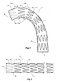
- Figures 3 and 4 shows an alternative stent graft.
- the tubular body 22 of the stent graft 20 is curved at its proximal end 24 to define an outer curved side 22a and an inner curved side 22b.
- the stents are tapered side to side and mounted onto the tubular body 22 such that the wider side 28 of the stent 26 is on the outer curve 22a and the narrower side 30 of the stent 26 is on the inner curve 22b.
- the stents 38 are on the substantially straight distal portion 40 of the stent graft 20.
- the spacing of the stents 26 and 32 is greater, as shown by dimensions 31a, on the outer curve 22a than on the inner curve 22b as is shown by the dimensions 31b.
- Figures 5A to 5D show various stylised stent grafts and Figures 6A to 6D show the stylised stent grafts in their curved forms.
- Figure 5A shows a stent graft with regular parallel sided stents 50 on a tubular body 52 but with buckled portions 54 between the first two stents on the outer curve side of the stent graft.
- Figure 5B shows a stent graft in which the tubular body 60 has a skewed stent 62, a straight-sided stent 64 and a further skewed stent 66 counting from the proximal end 60a.
- the tubular body has buckled portions 61 between each of the first three stents on the outer curve side of the stent graft.
- Figure 6B shows the arrangement of the embodiment shown in Figure 5B when in its curved form It will be noted that the buckles disappear and the stent graft can take up its curved shape and that there is a greater distance between the stents on the outer side of the curve that on the inner side of the curve.
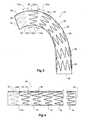
- Figure 5C and 6C show an arrangement where a tighter curve is desirable.
- the tubular body 70 has a greater curvature and the stents 72 at the proximal end 70a are each tapered with the wider side of the taper 72a on the outside of the curve 70b.
- Figure 5D and 6D show a still further arrangement in which a tubular body 80 has a first stent 82 which is tapered on a distal side thereof, a second stent 84 which is tapered on both sides and a third stent 86 which is tapered on only a proximal side thereof, and then subsequent stents 88 are regular.
- Figures 7A to 7D show various zig-zag self-expanding stents useful in explaining the present invention.
- Figure 7A shows a standard stent 90 formed from struts 91 and bends 92 at one end and 93 at the other end.
- the bends 92 at one end of the stent are in a first plane 92a which is substantially transverse to the longitudinal axis of the stent and the bends 93 at the other end of the stent are in a second plane 93a which is parallel to the first plane 92a and substantially transverse to the longitudinal axis of the stent.
- Figure 7B shows a skewed stent 95 which is in the form of a series of struts 96 and bends 97 at one end and 98 at the other end.
- the bends 97 form a plane 97a which is at an angle to the longitudinal axis of the stent graft and the bends 98 lie in a plane 98a which is at an angle to the longitudinal axis and substantially parallel to the plane 97a of the bends 97.
- Both the planes 97a and 98a are at an angle to normal planes 97b and 98b respectively at each end of the stent graft and are substantially parallel to each other.
- Stent 100 in Figure 7C is a half tapered stent with the bends 102 at one end being in a plane 102a which is substantially transverse or normal to the longitudinal axis of the stent graft but the bends 104 being in a plane 104a which is at an angle to the longitudinal axis of the stent graft.
- the plane 104a is at an angle to normal plane 104b and 102a respectively at each end of the stent graft.
- Figure 7D shows a stent 105 which is tapered on both ends such that the bends 106 form a first plane 106a which is at an angle and the bends 107 form a plane 107a which is at another angle. Both the planes 106a and 107a are at an angle to normal planes 106b and 107b respectively at each end of the stent graft.
- the wire which forms the stents can be stainless steel or Nitinol tm or any other suitable material.
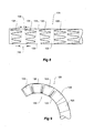
- FIGS 8 and 9 show an stent graft incorporating stents.
- the stent graft 120 has a tubular body 122 which at rest is substantially straight.
- the tubular body is supported by a plurality of stents comprising tapered stents 124 and straight stents 126.
- the stents are fastened to the tubular body by stitching or other suitable means.
- the stents 124 and 126 can be on the inside or the outside of the tubular body 122.
- the tapered stents are fastened to the tubular body so that their longest struts are on the same side 131 of the tubular body at a common circumferential position on the tubular body.
- the spacing of stents 128 is less than spacing 130 on a diametrically opposed side 133. This means that when the stent graft is bent with the wider portions of the stent on the outside of a curve such as in a curved vessel of the human or animal body the material of the other side 133 with the wider spacing 130 can buckle more to enable the stent graft to take up the curved shape.
- the stent graft 120 When the stent graft 120 is deployed within a curved vessel of the human or animal body with the longer struts of the stent on the outside of the curve the stent graft can take up the configuration shown in Figure 9 . It will be noted that the material of the stent graft buckles between the stents on the inside of the curve 132.
- FIG 10 shows an embodiment of a stent graft according to the present invention.
- the stent graft 132 according to the present invention comprises a tubular body 134 of a biocompatible graft material with the tubular body formed into a curve adjacent its proximal end 136 which approximates the curve of the thoracic arch of an aorta of a patient.
- the tubular body 134 is formed into the arcurate curve to define a outer curve 134a and an inner curve 134b.
- the tubular body towards the distal end 138 is substantially straight to match the descending aorta of a patient.
- the proximal-most stent 140 is inside the tubular body 134 and the remainder of these stents are on the outside of the tubular body.
- each of the stents 140, 142, 143 and 144 are of similar cylindrical configuration and are not tapered being of the type shown in Figure 7A .
- the stents 145, 146 and 147 are tapered with their longer sides 145a, 146a and 147a on the outer side 134a of the curved tubular body 134 and are of the type shown in Figure 7D .
- the stents are affixed to the tubular body by stitching or other suitable means (not shown).
- the spacing of the stents 145 and 146 is as shown by dimension 141 on the outer curve 134a is sufficient to enable the tubular body 134 to be circumferentially twisted through substantially half a turn between the stent 145 and the stent 146.
- the spacing of the stents 146 and 147 is sufficient to enable the tubular body 134 to be circumferentially twisted through substantially half a turn between the stent 146 and the stent 147.
- the proximal cylindrical stent 140 has a plurality of distally facing barbs 135 which when the stent graft is deployed and released with the thoracic arch engage with the wall of the aorta and prevent distal migration of the stent graft.
- Each of the stents 140, 145, 146, 147 and 142 has a radiopaque marker 150.
- the radiopaque marker 150 is positioned so that it is on the outer curve of the stent graft when mounted onto the stent graft.
- the radiopaque marker 150 is positioned on the longest strut of each stent so that again it is on the outer curve of the stent graft when mounted onto the stent graft.
- the radiopaque markers can be placed on the shortest strut and the line on the tubular graft material on the inner curve there may be provided on the graft material a longitudinal line (not shown) aligned with the inner curve.
- Figure 11 shows the stent graft of Figure 10 in a straightened and twisted form as it would be mounted onto a deployment device according to the present invention. In this state there would normally be a sheath holding the stent graft in the compressed condition but the sheath has been omitted so that the stent graft can be seen.
- the tubular body 134 of the stent graft 132 and each of the stents 140, 145, 146, 147, 142, 143 and 144 are radially compressed.
- the tubular body 134 is twisted circumferentially through approximately half a turn 152 so that the radiopaque marker 150 on stent 146 is on the other side of the tubular body.
- the tubular body 134 is twisted circumferentially through approximately half a turn 1 54 so that the radiopaque marker 150 on stent 147 is on the original side of the tubular body.
- the half a turn 154 is in the opposite direction than the half a turn 152 so that during deployment the tubular body distal of the stent 147 does not need to be rotated.
- the stent 146 is nested between the stents 145 and 147 because of the taper angles coinciding after the stent 146 has been rotated as discussed above.
- a stent graft which can be straightened for mounting onto and delivery by an introduction system and when released will take up a curved shape to conform to the curved shape of the vessel into which it is delivered.
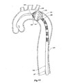
- Figures 12 to 17 show a schematic view of the thoracic arch and descending aorta of a patient with a deployment device including a stent graft according to the present invention deployed into the thoracic arch and the sequential stages of deployment of the stent graft similar to that shown in Figures 10 and 11 .
- the twists 152 and 154 are in the same circumferential direction.
- FIG 12 shows a schematic view of the aorta of a patient.
- the aorta commences at the aortic valve 180 of the heart and an ascending aorta 182 extends to the arch vessels 183 at the thoracic arch 184 and then the descending aorta 185 extends down the truck of the body of the patient.
- a guide wire 188 has been introduced to extend over thoracic arch towards aortic valve 180 and over that guide wire has been advanced a deployment device 190.
- the deployment device 190 includes a nose cone dilator 192 and a sheath 194 extending up to the nose cone dilator.
- the sheath 194 is shown transparent so that the stent graft 132 and stents 140, 145 and 146 restrained in a contracted condition within the introduction device and the radiopaque markers 1 50 can be seen.
- the introducer 190 is advanced to the desired placement site for the stent graft and rotated so that the opaque marker 150 on the first stent 140 and second stent 145 from the proximal end 136 are on the outer side of the curve as can be seen by the position of the radiopaque markers 150.
- a release arrangement 196 (which is mounted on a release handle (not shown) for the delivery device 190) for the proximal end 1 36 of the stent graft 196 is actuated as shown by the arrow 189 so that the proximal end 136 expands to the diameter of the aorta and the barbs 135 engage into the wall of the aorta.
- the delivery device 190 is rotated in a clockwise direction as shown by the arrow 191 to release the twist 152 and to bring the marker 150 on the stent 146 to the outside of the curve.
- the stent 146 is still retained within the sheath 194.
- the sheath 194 of the delivery device 190 is then retracted as shown by the arrow 193 to release the stent 146 so that it can expand to the diameter of the vessel.
- the twist 154 between the stent 146 and stent 147 is partially exposed.
- the stent 147 is still retained within the sheath 194.
- the sheath 194 can again be rotated as shown by the arrow 195 to release the twist 154 and bring the marker 150 on the stent 147 to the outside of the curve.
- the sheath 194 of the deployment device 190 is then retracted so that the stents 17 and 12, 13 and 14 are exposed as shown in Figure 17 .
- the entire delivery device can then be removed leaving the stent graft in position in the thoracic arch and descending aorta.
- an alternative release arrangement can be used. After the stage shown in Figure 14 when the proximal end of the stent graft has been released to engage the walls of the vessel retraction of the sheath 194 with continued tension on the material of the stent graft will cause the stent 146 to rotate automatically to its desired position with its longer struts on the outside of the curve. This means that there does not have to be any rotation of the delivery device between the release of the stents. This may be advantageous where the vasculature is very distorted.
- the degree of twist between adjacent stents may be greater or less than half a turn.
- the number and pattern of twists may be selected as desired.
- a method of loading a stent graft into an introducer sheath 194 of a delivery system will now be described.
- the straight z-stents of graft are loaded into the introducer sheath in a conventional manner.
- the stent-graft is then loaded while ensuring that the longitudinal indexing stripes are in line.
- a stent-crimper is placed over a first wedge shaped stent and the stent is compressed.
- the delivery system is rotated through 180° until an indexing strip for the outside of the radius (e.g. green) is brought into alignment with an indexing stripe for the inside of the radius (e.g. red).
- the first wedge-shaped stent is then pulled into the delivery sheath. These rotation and pulling steps are then repeated until the last wedge-shaped stent has been loaded into the delivery sheath 194.
- the proximal barbed z-stent is then loaded in the conventional manner.
- FIG 18A shows an alternative embodiment of stent graft according to the present invention.
- the stent graft 200 has the tapered stents 202, 204 and 206 sewn onto the curved tubular body 201 with a slight twist 207 engineered into the stent graft material to compensate for the opposite twist needed for nesting the stents in the delivery system when it is mounted into the delivery system.
- Figure 18B shows an alternative embodiment of stent graft according to the present invention.
- the stent graft 210 the tapered stents 212, 214 and 216 sewn onto the curved tubular body 21 with directional sewing 217 to allow the twisting needed for nesting stents in the delivery system to extend under the stents 212, 214 and 216.
- FIG 18C shows an alternative embodiment of stent graft according to the present invention.
- the stent graft 220 tapered stents 222, 224 and 226 are sewn into the curved tubular body 221 with a combination of directional sewing stitches 227 and stitches 228a through eyelet 228 at the bends at a first end of each stent.
- the stitching through each eyelet keeps the first end of each stent in its selected place on the tubular body but enables movement of graft material under each stent at the other end of each stent.
- FIG 18D shows a still further embodiment of stent graft 230 according to the present invention.
- the tapered stents 232, 234 and 236 are sewn into the curved tubular body 231 with stitches 238a through eyelets 238 at the bends at a first end of each stent.
- the stitching through each eyelet keeps the first end of each stent in its selected place on the tubular body but enables movement of graft material under each stent at the second end of each stent.
- a stent graft assembly can be formed which will more easily take up the form of a curved portion of a vasculature of a patient.
Abstract
Description
- This invention relates to a medical device and more particularly a stent and a stent graft incorporating the stent for deployment within the human or animal body and to a method by which such a stent graft can be loaded into an introducer sheath. It particularly relates to a thoracic arch stent graft.
- Stent grafts are used to replace or repair vessels of the body such as the blood vessels. A stent graft is usually formed from a tubular body of a biocompatible graft material and one or more stents are mounted into or onto the tubular body to provide support for the tubular body. The stents may be balloon expandable stents or self-expanding stents. This invention will be discussed with reference to the use of self-expanding stents but the invention is not limited to that and may be used with balloon expandable stents or other forms of stents.
- Where a stent graft is to be placed into a curved blood vessel, and it is desired to maintain that curve, it is desirable to have the stent graft set into the approximate shape of the curve to prevent buckling of the stent graft in the vessel which may occlude some of the flow path in the vessel.
- Stent grafts are deployed using endovascular techniques on an introduction device in which the stent graft is retained in a radially contracted condition by a sheath. Upon retraction of the sheath and release of any retention arrangement where necessary, where the stent graft has self expanding stents, the stent graft can expand under the action of the self expanding stents towards the vessel walls to define a blood flow path and the introduction device can be withdrawn.
- There can be a problem with mounting of a stent graft designed for a curved vessel onto an essentially straight catheter of a deployment device. The catheter of a deployment device is essentially straight to enable it to be introduced through the vasculature of a patient via a femoral artery using the Seldinger technique.
-
US2002/052644 A1 discloses a stent graft with tapering stent elements. Curving of the graft is permitted by sliding links.WO03/034948 A US2006/030926 A1 discloses a graft with spaced stents with parallel ends therealong and expandable portions which flex between an expanded configuration when the graft is straight and a compressed configuration when the graft is curved. The disclosure of this document corresponds generally to the preamble of claim 1. - Aspects of the present invention seek to provide a stent, and a stent graft incorporating the stent which stent graft will form at least in part the shape of a curved vessel and to a method of deploying such a stent graft or to at least provide the physician with a useful alternative.
- Throughout this specification the term distal with the respect to a portion of the aorta, a deployment device or a prosthesis means the end of the aorta, deployment device or prosthesis further away in the direction of blood flow away from the heart and the term proximal means the portion of the aorta, deployment device or end of the prosthesis nearer to the heart. When applied to other vessels similar terms such as caudal and cranial should be understood.
- According to a first aspect of the present invention there is provided a stent member comprising a plurality of axially spaced stent elements located on a tubular body of graft material, the stent elements being configured to be capable of movement relative to each other such that the stent member is capable of moving between a first configuration in which it is substantially straight, and a second configuration in which at least a part thereof is curved, at least some of the stent elements being located on the tubular body such that there is a greater distance between adjacent stent elements on one side than on the other side of the tubular body, characterised in that at least some of the stent elements are located on the tubular body such that the tubular body can be twisted to move the stent elements relative to each other.
- The two configurations enable a stent member, which is to be curved when in its final position in use, to be loaded into a deployment device and inserted through a body lumen when in a straight disposition. The relative twisting movement of the stents means that they may move towards and nest with each other when being inserted into a delivery sheath.
- Preferably, one or more of the stent elements each comprises a generally cylindrical body having substantially planar ends defining respective planar transverse to the longitudinal axis of the cylindrical body, wherein at least one of the planes is angled with respect to a plane at right angles to the longitudinal axis of the cylindrical body whereby the stent is tapered on one or both ends or is skewed.
- In a preferred arrangement, in regard to a first spacing between stent elements, the stent elements are arranged so that the twist is clockwise and, in regard to a second spacing between stent elements, the stent elements are arranged so that the twist is anti-clockwise. This provides a particularly compact arrangement and can lead to a simpler deployment process.
- In a preferred embodiment, at least some of the stent elements are secured to the tubular body so as to permit relative movement therebetween. In particular, the stent elements may be sewn to the tubular body in such a way as to permit said relative movement. For example the stent elements can be sewn into the tubular body with a slight twist engineered into the stent graft material. Alternatively, or in addition, the stent elements are attached to the tubular body by attachment means at or adjacent one end to permit said relative movement. Eyelets may be provided as the attachment means.
- Preferably, at least some of the stent elements have markers, the position of which can be detected. The markers may all be arranged on the outside of the curve of the stent member when it is fully deployed, or all on the inside. Alternatively, one type of marker may be on the outside and another type on the inside of the curve. The markers may be radio-opaque markers, which makes them easy to track within a body lumen.
- According to a second aspect of the present invention, there is provided a method of loading a stent graft, at least a part of which is configured to be curved when deployed, into an introducer sheath, the stent graft comprising a plurality of mutually-spaced stent elements attached to a tubular body of graft material, the method comprising inserting the graft as far as one or more stent elements thereon into the sheath and before inserting the next stent element into the sheath, twisting the graft whereby to at least partially close up the gap between adjacent stent elements.
- One preferred embodiment provides a stent comprising a wire formed into a plurality of struts and bends between adjacent struts, the struts defining a cylindrical body and the bends at each end defining respective planes transverse to the longitudinal axis of the cylindrical body wherein at least one of the planes is angled with respect to a plane at right angles to the longitudinal axis of the cylindrical body whereby the stent is tapered on one or both ends or is skewed. Preferably the stent is a zig zag stent comprising longer struts and shorter struts.
- Preferably the wire is stainless steel or a shape memory whereby to form a self expanding stent.
- In an alternative embodiment, there is provided a stent graft for curved lumens of the body, the stent graft comprising a tubular body of graft material, at least a portion of which is arcuate to define an inner curved side and an outer curved side, the stent graft comprising a plurality of self expanding stents affixed thereto and spaced apart along at least a portion of the tubular body, there being a greater spacing apart between adjacent stents on the outer curved side than on the inner curved side on at least the arcuate portion of the tubular body.
- Preferably the stents are zig-zag self expanding stents having a plurality of struts and bends between adjacent struts.
- Preferably at least some of the stents are normal stents comprising a wire formed into a plurality of struts and bends between adjacent struts, the struts defining a cylindrical body and the bends at each end defining respective planes transverse to the longitudinal axis of the cylindrical body with the planes substantially parallel to each other and substantially at right angles to the longitudinal axis of the cylindrical body and at least some of the stents are tapered stents comprising a wire formed into a plurality of struts and bends between adjacent struts, the struts defining a cylindrical body and the bends at each end defining respective planes transverse to the longitudinal axis of the cylindrical body with at least one of the planes being angled with respect to the plane at right angles to the longitudinal axis of the cylindrical body whereby to define a tapered stent having one or two tapered ends.
- Preferably at least some of the stents are tapered to define longer struts and shorter struts and the tapered stents are affixed to the tubular body with the longer struts on the outer curved side and the shorter struts on the inner curved side.
- Preferably the tapered stents are mounted to the tubular body with the longer side on the outer curve of the tubular body.
- Preferably the stent graft comprises first, second, third and subsequent stents from its proximal end, the first stent being a skewed stent, the second stent being a normal stent and the third stent being a skewed stent, the skew on the third stent being opposite to that of the first stent.
- Alternatively the stent graft comprises first, second, third and subsequent stents from its proximal end, the first, second and third stents being tapered stents and wherein the tapered stents are mounted to the tubular body with their longer sides on the outer curve of the tubular body.
- Alternatively the stent graft comprises first, second, third and subsequent stents from its proximal end, the first, second and third stents being tapered stents, the first stent comprising a taper on its distal end, the second stent comprising a taper at both its proximal and distal ends and the third stent comprising a taper on its proximal end and wherein the tapered stents are mounted to the tubular body with their longer sides on the outer curve of the tubular body.
- Alternatively the stent graft comprises first, second, third and subsequent stents from its proximal end, the first stent being a tapered stent, the second stent being a normal stent and the third stent being a tapered stent and wherein the tapered stents are mounted to the tubular body with their longer sides on the outer curve of the tubular body.
- Preferably the proximal-most stent is inside the tubular body and the remaining stents are on the outside of the tubular body.
- Preferred embodiments of the invention provide a stent graft for curved lumens of the body, the stent graft having a tubular body of a graft material, at least a portion of which is arcuate to define an inner curved side and an outer curved side, the stent graft having a plurality of self expanding stents affixed thereto, at least some of the stents being tapered to define longer struts and shorter struts and the tapered stents being affixed to the tubular body with the longer struts on the outer curved side and the shorter struts on the inner curved side, the tapered stents being spaced apart longitudinally on the tubular body whereby the tubular body can be twisted substantially by half a turn between at least some of the adjacent stents when loaded into a deployment device whereby to nest the stents in the deployment device.
- Preferably the tapered stents comprise a plurality of struts and bends between adjacent struts, the struts defining a cylindrical body and the bends at each end defining respective planes transverse to the longitudinal axis of the cylindrical body, and wherein at least one of the planes of the bends are at an angle transverse to the longitudinal axis of the cylindrical body, whereby to define a tapered stent comprising one or two tapered ends and wherein the tapered stent is mounted to the tubular body with the longer side on the outer curve of the tubular body.
- Preferably the tapered stents are fastened to the tubular body at only their proximal or distal ends of the stent or intermediate their ends.
- Preferably the circumferential twisting between adjacent tapered stents is each clockwise or anticlockwise twisting or alternatively clockwise and anticlockwise.
- Preferably each of at least the tapered stents includes a radiopaque marker whereby the relative position of a stent being deployed with respect to a stent already deployed can be determined during deployment.
- Preferably at least some of the stents have a marker on their longer sides whereby during deployment the introduction device can be rotated as each stent is released to ensure that each stent and hence the tubular body is correctly placed so that the arcuate portion is in a curved vessel in the desired orientation.
- Other embodiments of the invention provide a stent graft introduction device in combination with a stent graft, the stent graft comprising a tubular body of a biocompatible graft material and comprising at least a portion nearer the proximal end thereof which is arcuate to define an inner curved side and an outer curved side, the stent graft having a plurality of stents affixed thereto, a first stent at the proximal end being a cylindrical normal self expanding stent, at least the next three stents being tapered stents and the balance of the stents to the distal end of the tubular body being cylindrical normal stents, the tapered stents being mounted to the tubular body such that their longer sides are on the outer curved side of the tubular body, at least the tapered stents having radiopaque markers thereon to facilitate alignment during deployment, the stent graft being retained on the introduction device such that there is a twist in one circumferential direction between the first tapered stent and a second tapered stent and a further twist in the same or the opposite circumferential direction between the second tapered stent and a third tapered stent whereby to nest adjacent stents with each other on the deployment device.
- Although this invention is discussed in relation to deployment of a stent graft into the thoracic arch of a patient, the invention is not so limited and may be applied to other vessels of the human or animal body.
- Preferred embodiments of the present invention will now be described, by way of example only, with reference to the accompanying drawings of which:
-
Figure 1 shows a stent graft useful in explaining the present invention; -
Figure 2 shows the stent graft inFigure 1 in straightened format; -
Figure 3 shows an alternative stent graft useful in explaining the present invention; -
Figure 4 shows the stent graft inFigure 3 in straightened format; -
Figure 5A to 5D shows various stent grafts in stylised format; -
Figure 6A to 6D shows the grafts ofFigures 5A to 5D in a curved form; -
Figures 7A to 7D show various format of stent useful in explaining the present invention; -
Figure 8 shows a portion of a further stent graft useful in explaining the present invention; -
Figure 9 shows the stent graft ofFigure 8 when in a curved configuration; -
Figure 10 shows an embodiment of a stent graft according to the present invention; -
Figure 11 shows the stent graft ofFigure 10 in a radially contracted and twisted condition for deployment. -
Figure 12 shows a schematic view of the thoracic arch and descending aorta of a patient with a deployment device including a stent graft similar to the embodiment ofFigure 10 of the present invention deployed into the thoracic arch; -
Figures 13 to 17 show sequential stages of deployment of the stent graft shown inFigure 11 ; -
Figure 18A shows an embodiment of a stent graft according to the present invention; -
Figure 18B shows a further embodiment of a stent graft according to the present invention specifically showing an alternative mounting of stents onto the graft material; -
Figure 18C shows another embodiment of a stent graft according to the present invention specifically showing an alternative mounting of stents onto the graft material; and -
Figure 18D shows an embodiment of a stent graft according to the present invention specifically showing an alternative mounting of stents onto the graft material. - Referring now to the drawings and in particular
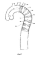
Figures 1 and 2 , it will be seen that astent graft 2 comprises atubular body 4 of a biocompatible graft material with the tubular body formed into a curve at its proximal end 6 which approximates the curve of the thoracic arch of an aorta of a patient. Thetubular body 4 formed into the arcuate curve has aouter curve 4a and aninner curve 4b. Thedistal end 8 is substantially straight to match the descending aorta of a patient. In this embodiment, theproximal-most stent 10 is inside thetubular body 4 and the remainder of these stents are on the outside of the tubular body. - Each of the
stents - The spacing of the
stents dimension 11a, on theouter curve 4a than on theinner curve 4b as is shown by thedimension 11b. -
Figure 2 shows the stent graft ofFigure 1 in a straightened format and to allow for thegreater distance 11a (Figure 1 ) between thefirst stent 10 andsecond stent 12 from the proximal end 6, theouter curve 4a is buckled at 14. At theinner curve 4b the graft material is not buckled between the stents. - Hence there is provided a stent graft which can be straightened for delivery by an introduction system and when released will take up a curved shape to conform to the curved shape of the vessel into which it is delivered.
-
Figures 3 and 4 shows an alternative stent graft. - Again, the
tubular body 22 of thestent graft 20 is curved at itsproximal end 24 to define an outercurved side 22a and an innercurved side 22b. In this embodiment, the stents are tapered side to side and mounted onto thetubular body 22 such that thewider side 28 of thestent 26 is on theouter curve 22a and thenarrower side 30 of thestent 26 is on theinner curve 22b. In this embodiment, there are four similarly taperedstents proximal end 24 and three standarduntapered stents 38 along the balance of the stent graft to thedistal end 40. Thestents 38 are on the substantially straightdistal portion 40 of thestent graft 20. - The spacing of the
stents dimensions 31a, on theouter curve 22a than on theinner curve 22b as is shown by thedimensions 31b. - Again as shown in
Figure 4 , when the stent is straightened out for loading into a deployment device, theouter side 22a of thetubular body 22 buckles at 42 but theinner side 22b is not buckled. -
Figures 5A to 5D show various stylised stent grafts andFigures 6A to 6D show the stylised stent grafts in their curved forms. -
Figure 5A shows a stent graft with regular parallelsided stents 50 on atubular body 52 but with buckledportions 54 between the first two stents on the outer curve side of the stent graft. Now looking atFigure 6A , when the tubular body is put into its normal curved shape, it will be noted that the buckles disappear and the stent graft can take up its curved shape and that there is a greater distance between the stents on the outer side of the curve than on the inner side of the curve. -
Figure 5B shows a stent graft in which thetubular body 60 has a skewedstent 62, a straight-sidedstent 64 and a further skewedstent 66 counting from theproximal end 60a. The tubular body has buckledportions 61 between each of the first three stents on the outer curve side of the stent graft.Figure 6B shows the arrangement of the embodiment shown inFigure 5B when in its curved form It will be noted that the buckles disappear and the stent graft can take up its curved shape and that there is a greater distance between the stents on the outer side of the curve that on the inner side of the curve. -
Figure 5C and6C show an arrangement where a tighter curve is desirable. In this embodiment, thetubular body 70 has a greater curvature and thestents 72 at theproximal end 70a are each tapered with the wider side of thetaper 72a on the outside of thecurve 70b. -
Figure 5D and6D show a still further arrangement in which atubular body 80 has afirst stent 82 which is tapered on a distal side thereof, asecond stent 84 which is tapered on both sides and athird stent 86 which is tapered on only a proximal side thereof, and thensubsequent stents 88 are regular. -
Figures 7A to 7D show various zig-zag self-expanding stents useful in explaining the present invention. -
Figure 7A shows astandard stent 90 formed fromstruts 91 and bends 92 at one end and 93 at the other end. Thebends 92 at one end of the stent are in afirst plane 92a which is substantially transverse to the longitudinal axis of the stent and thebends 93 at the other end of the stent are in asecond plane 93a which is parallel to thefirst plane 92a and substantially transverse to the longitudinal axis of the stent. -
Figure 7B shows askewed stent 95 which is in the form of a series ofstruts 96 and bends 97 at one end and 98 at the other end. Thebends 97 form aplane 97a which is at an angle to the longitudinal axis of the stent graft and thebends 98 lie in aplane 98a which is at an angle to the longitudinal axis and substantially parallel to theplane 97a of thebends 97. Both theplanes normal planes -
Stent 100 inFigure 7C is a half tapered stent with thebends 102 at one end being in aplane 102a which is substantially transverse or normal to the longitudinal axis of the stent graft but thebends 104 being in aplane 104a which is at an angle to the longitudinal axis of the stent graft. Theplane 104a is at an angle tonormal plane -
Figure 7D shows astent 105 which is tapered on both ends such that thebends 106 form afirst plane 106a which is at an angle and thebends 107 form aplane 107a which is at another angle. Both theplanes normal planes - The wire which forms the stents can be stainless steel or Nitinoltm or any other suitable material.
-
Figures 8 and 9 show an stent graft incorporating stents. Thestent graft 120 has atubular body 122 which at rest is substantially straight. The tubular body is supported by a plurality of stents comprising taperedstents 124 andstraight stents 126. The stents are fastened to the tubular body by stitching or other suitable means. Thestents tubular body 122. The tapered stents are fastened to the tubular body so that their longest struts are on the same side 131 of the tubular body at a common circumferential position on the tubular body. Between the taperedstents 124 on that side 131 of the tubular body the spacing ofstents 128 is less than spacing 130 on a diametricallyopposed side 133. This means that when the stent graft is bent with the wider portions of the stent on the outside of a curve such as in a curved vessel of the human or animal body the material of theother side 133 with thewider spacing 130 can buckle more to enable the stent graft to take up the curved shape. - When the
stent graft 120 is deployed within a curved vessel of the human or animal body with the longer struts of the stent on the outside of the curve the stent graft can take up the configuration shown inFigure 9 . It will be noted that the material of the stent graft buckles between the stents on the inside of thecurve 132. -
Figure 10 shows an embodiment of a stent graft according to the present invention. Thestent graft 132 according to the present invention comprises atubular body 134 of a biocompatible graft material with the tubular body formed into a curve adjacent itsproximal end 136 which approximates the curve of the thoracic arch of an aorta of a patient. Thetubular body 134 is formed into the arcurate curve to define aouter curve 134a and aninner curve 134b. The tubular body towards thedistal end 138 is substantially straight to match the descending aorta of a patient. In this embodiment, theproximal-most stent 140 is inside thetubular body 134 and the remainder of these stents are on the outside of the tubular body. - In this embodiment, each of the
stents Figure 7A . Thestents longer sides outer side 134a of the curvedtubular body 134 and are of the type shown inFigure 7D . The stents are affixed to the tubular body by stitching or other suitable means (not shown). The spacing of thestents dimension 141 on theouter curve 134a is sufficient to enable thetubular body 134 to be circumferentially twisted through substantially half a turn between thestent 145 and thestent 146. Similarly the spacing of thestents tubular body 134 to be circumferentially twisted through substantially half a turn between thestent 146 and thestent 147. - The proximal
cylindrical stent 140 has a plurality of distally facingbarbs 135 which when the stent graft is deployed and released with the thoracic arch engage with the wall of the aorta and prevent distal migration of the stent graft. - Each of the
stents radiopaque marker 150. On thecylindrical stents radiopaque marker 150 is positioned so that it is on the outer curve of the stent graft when mounted onto the stent graft. On the taperedstents radiopaque marker 150 is positioned on the longest strut of each stent so that again it is on the outer curve of the stent graft when mounted onto the stent graft. For the purpose of assisting alignment of the radiopaque markers on the stents onto the tubular graft material on the outer curve there may be provided on the graft material a longitudinal line (not shown) aligned with the outer curve. - Alternatively the radiopaque markers can be placed on the shortest strut and the line on the tubular graft material on the inner curve there may be provided on the graft material a longitudinal line (not shown) aligned with the inner curve.
-
Figure 11 shows the stent graft ofFigure 10 in a straightened and twisted form as it would be mounted onto a deployment device according to the present invention. In this state there would normally be a sheath holding the stent graft in the compressed condition but the sheath has been omitted so that the stent graft can be seen. Thetubular body 134 of thestent graft 132 and each of thestents stent 145 and thestent 146 thetubular body 134 is twisted circumferentially through approximately half aturn 152 so that theradiopaque marker 150 onstent 146 is on the other side of the tubular body. Between thestent 146 and thestent 147 thetubular body 134 is twisted circumferentially through approximately half a turn 1 54 so that theradiopaque marker 150 onstent 147 is on the original side of the tubular body. The half aturn 154 is in the opposite direction than the half aturn 152 so that during deployment the tubular body distal of thestent 147 does not need to be rotated. - It will be noted that the
stent 146 is nested between thestents stent 146 has been rotated as discussed above. - Hence there is provided by this embodiment of the invention shown in
Figures 10 and 11 a stent graft which can be straightened for mounting onto and delivery by an introduction system and when released will take up a curved shape to conform to the curved shape of the vessel into which it is delivered. -
Figures 12 to 17 show a schematic view of the thoracic arch and descending aorta of a patient with a deployment device including a stent graft according to the present invention deployed into the thoracic arch and the sequential stages of deployment of the stent graft similar to that shown inFigures 10 and 11 . In the arrangement shown inFigures 12 to 17 , however, thetwists -
Figure 12 shows a schematic view of the aorta of a patient. The aorta commences at theaortic valve 180 of the heart and an ascendingaorta 182 extends to thearch vessels 183 at thethoracic arch 184 and then the descendingaorta 185 extends down the truck of the body of the patient. Aguide wire 188 has been introduced to extend over thoracic arch towardsaortic valve 180 and over that guide wire has been advanced adeployment device 190. Thedeployment device 190 includes anose cone dilator 192 and asheath 194 extending up to the nose cone dilator. Thesheath 194 is shown transparent so that thestent graft 132 andstents - The
introducer 190 is advanced to the desired placement site for the stent graft and rotated so that theopaque marker 150 on thefirst stent 140 andsecond stent 145 from theproximal end 136 are on the outer side of the curve as can be seen by the position of theradiopaque markers 150. - The next stage is shown in
Figure 13 . - In
Figure 13 thesheath 194 of theintroduction device 190 has been retracted as shown by thearrow 187 so that thefirst stent 140 andsecond stent 145 are released from the sheath. At this stage theproximal end 136 of the stent graft is still retained onto the delivery device by a retention and release means (not shown). It will be noted, too, that thetwist 152 in the graft material between thestent 145 andstent 146 can be seen. - In the next stage as shown in
Figure 14 a release arrangement 196 (which is mounted on a release handle (not shown) for the delivery device 190) for the proximal end 1 36 of thestent graft 196 is actuated as shown by thearrow 189 so that theproximal end 136 expands to the diameter of the aorta and thebarbs 135 engage into the wall of the aorta. - In the next stage as shown in
Figure 15 thedelivery device 190 is rotated in a clockwise direction as shown by thearrow 191 to release thetwist 152 and to bring themarker 150 on thestent 146 to the outside of the curve. At this stage, however, thestent 146 is still retained within thesheath 194. - In the next stage as shown in
Figure 16 thesheath 194 of thedelivery device 190 is then retracted as shown by thearrow 193 to release thestent 146 so that it can expand to the diameter of the vessel. At this stage thetwist 154 between thestent 146 andstent 147 is partially exposed. At this stage, however, thestent 147 is still retained within thesheath 194. - The
sheath 194 can again be rotated as shown by thearrow 195 to release thetwist 154 and bring themarker 150 on thestent 147 to the outside of the curve. Thesheath 194 of thedeployment device 190 is then retracted so that thestents Figure 17 . The entire delivery device can then be removed leaving the stent graft in position in the thoracic arch and descending aorta. - In an alternative arrangement where the
twists 152 and 1 54 are formed in opposite circumferential directions an alternative release arrangement can be used. After the stage shown inFigure 14 when the proximal end of the stent graft has been released to engage the walls of the vessel retraction of thesheath 194 with continued tension on the material of the stent graft will cause thestent 146 to rotate automatically to its desired position with its longer struts on the outside of the curve. This means that there does not have to be any rotation of the delivery device between the release of the stents. This may be advantageous where the vasculature is very distorted. - The degree of twist between adjacent stents may be greater or less than half a turn. The number and pattern of twists may be selected as desired.
- A method of loading a stent graft into an
introducer sheath 194 of a delivery system will now be described. After the proximal component trigger-wires are routed and engaged, the straight z-stents of graft are loaded into the introducer sheath in a conventional manner. The stent-graft is then loaded while ensuring that the longitudinal indexing stripes are in line. A stent-crimper is placed over a first wedge shaped stent and the stent is compressed. - In the next stage of the insertion process, the delivery system is rotated through 180° until an indexing strip for the outside of the radius (e.g. green) is brought into alignment with an indexing stripe for the inside of the radius (e.g. red). The first wedge-shaped stent is then pulled into the delivery sheath. These rotation and pulling steps are then repeated until the last wedge-shaped stent has been loaded into the
delivery sheath 194. The proximal barbed z-stent is then loaded in the conventional manner. -
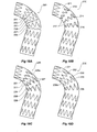
Figure 18A shows an alternative embodiment of stent graft according to the present invention. In this embodiment thestent graft 200 has the taperedstents tubular body 201 with aslight twist 207 engineered into the stent graft material to compensate for the opposite twist needed for nesting the stents in the delivery system when it is mounted into the delivery system. -
Figure 18B shows an alternative embodiment of stent graft according to the present invention. In this embodiment thestent graft 210 the taperedstents directional sewing 217 to allow the twisting needed for nesting stents in the delivery system to extend under thestents -
Figure 18C shows an alternative embodiment of stent graft according to the present invention. In this embodiment thestent graft 220 taperedstents tubular body 221 with a combination of directional sewing stitches 227 andstitches 228a througheyelet 228 at the bends at a first end of each stent. The stitching through each eyelet keeps the first end of each stent in its selected place on the tubular body but enables movement of graft material under each stent at the other end of each stent. -
Figure 18D shows a still further embodiment ofstent graft 230 according to the present invention. In this embodiment the taperedstents tubular body 231 withstitches 238a througheyelets 238 at the bends at a first end of each stent. The stitching through each eyelet keeps the first end of each stent in its selected place on the tubular body but enables movement of graft material under each stent at the second end of each stent. - It will be seen that by this invention a stent graft assembly can be formed which will more easily take up the form of a curved portion of a vasculature of a patient.
- The features of the various embodiments and modifications described may be interchanged or combined as desired.
Claims (8)
- A stent member (2, 20, 120, 132, 200, 210, 220, 230) comprising a plurality of axially spaced stent elements (10, 12, 13; 26, 32, 34, 36) located on a tubular body (4; 134) of graft material, the stent elements being configured to be capable of movement relative to each other such that the stent member is capable of moving between a first configuration in which it is substantially straight, and a second configuration in which at least a part thereof is curved, at least some of the stent elements (26, 32, 34, 36) being located on the tubular body such that there is a greater distance between adjacent stent elements on one side than on the other side of the tubular body, characterised in that at least some of the stent elements are located on the tubular body (4; 134) such that the tubular body can be twisted to move the stent elements relative to each other.
- A stent member (2, 20, 120, 132, 200, 210, 220, 230) according to claims 1, wherein one of more of the stent elements (26, 32, 34, 36; 62, 66, 72, 82, 84, 86; 95, 100, 105; 124; 145, 146, 147; 202, 204, 206; 212, 214, 216; 222, 224, 226; 232, 234, 236) each comprises a generally cylindrical body having substantially planar ends defining respective planar transverse to the longitudinal axis of the cylindrical body, wherein at least one of the planes is angled with respect to a plane at right angles to the longitudinal axis of the cylindrical body whereby the stent is tapered on one or both end or is skewed.
- A stent member according to claim 1 or 2 wherein, in regard to a first spacing between stent elements, the stent elements are arranged so that the twist is clockwise and, in regard to a second spacing between stent elements, the stent elements are arranged so that the twist is anti-clockwise.
- A stent member according to any preceding claim, wherein at least some of the stent elements (202, 204, 206; 212, 214, 216; 222, 224, 226; 232, 234, 236) are secured to the tubular body so as to permit relative movement therebetween.
- A stent member according to claim 4, wherein the stent elements (202, 204, 206; 212, 214, 216; 222, 224, 226) are sewn to the tubular body in such a way as to permit said relative movement.
- A stent member according to claim 4 or 5, wherein the stent elements (222, 224, 226; 232, 234, 236) are attached to the tubular body by attachment means (228; 238) at or adjacent one end to permit said relative movement.
- A stent member according to any preceding claims, wherein at least some of the stent elements have markers, the position of which can be detected.
- A method of loading a stent graft (132), at least a part of which is configured to be curved when deployed, into an introducer sheath (194), the stent graft comprising a plurality of mutually-spaced stent elements (140-147) attached to a tubular body (134) of graft material, the method comprising inserting the graft as far as one or more stent elements thereon into the sheath and before inserting the next stent element into the sheath, twisting the graft whereby to at least partially close up the gap between adjacent stent elements.
Applications Claiming Priority (3)
| Application Number | Priority Date | Filing Date | Title |
|---|---|---|---|
| US85391506P | 2006-10-24 | 2006-10-24 | |
| US85391406P | 2006-10-24 | 2006-10-24 | |
| PCT/US2007/022488 WO2008051543A2 (en) | 2006-10-24 | 2007-10-23 | Stent member |
Publications (2)
| Publication Number | Publication Date |
|---|---|
| EP2079397A2 EP2079397A2 (en) | 2009-07-22 |
| EP2079397B1 true EP2079397B1 (en) | 2010-03-24 |
Family
ID=39215238
Family Applications (1)
| Application Number | Title | Priority Date | Filing Date |
|---|---|---|---|
| EP07852901A Active EP2079397B1 (en) | 2006-10-24 | 2007-10-23 | Stent member |
Country Status (5)
| Country | Link |
|---|---|
| US (1) | US8425585B2 (en) |
| EP (1) | EP2079397B1 (en) |
| AT (1) | ATE461675T1 (en) |
| DE (1) | DE602007005504D1 (en) |
| WO (1) | WO2008051543A2 (en) |
Cited By (1)
| Publication number | Priority date | Publication date | Assignee | Title |
|---|---|---|---|---|
| EP3943046A1 (en) * | 2011-09-27 | 2022-01-26 | Cook Medical Technologies LLC | Endoluminal prosthesis with steerable branch |
Families Citing this family (61)
| Publication number | Priority date | Publication date | Assignee | Title |
|---|---|---|---|---|
| US8425549B2 (en) | 2002-07-23 | 2013-04-23 | Reverse Medical Corporation | Systems and methods for removing obstructive matter from body lumens and treating vascular defects |
| CN2817768Y (en) * | 2005-05-24 | 2006-09-20 | 微创医疗器械(上海)有限公司 | Tectorium stand and host cage section thereof |
| EP2079397B1 (en) | 2006-10-24 | 2010-03-24 | Cook Incorporated | Stent member |
| WO2008053469A2 (en) * | 2006-10-29 | 2008-05-08 | Alon Shalev | An extra-vascular wrapping for treating aneurysmatic aorta and methods thereof |
| EP2142142B1 (en) | 2007-03-05 | 2017-02-08 | Endospan Ltd | Multi-component expandable supportive bifurcated endoluminal grafts and methods for using same |
| US8545514B2 (en) | 2008-04-11 | 2013-10-01 | Covidien Lp | Monorail neuro-microcatheter for delivery of medical devices to treat stroke, processes and products thereby |
| US11337714B2 (en) | 2007-10-17 | 2022-05-24 | Covidien Lp | Restoring blood flow and clot removal during acute ischemic stroke |
| US8926680B2 (en) | 2007-11-12 | 2015-01-06 | Covidien Lp | Aneurysm neck bridging processes with revascularization systems methods and products thereby |
| US8066757B2 (en) * | 2007-10-17 | 2011-11-29 | Mindframe, Inc. | Blood flow restoration and thrombus management methods |
| US9220522B2 (en) | 2007-10-17 | 2015-12-29 | Covidien Lp | Embolus removal systems with baskets |
| US8088140B2 (en) | 2008-05-19 | 2012-01-03 | Mindframe, Inc. | Blood flow restorative and embolus removal methods |
| US9198687B2 (en) | 2007-10-17 | 2015-12-01 | Covidien Lp | Acute stroke revascularization/recanalization systems processes and products thereby |
| US10123803B2 (en) | 2007-10-17 | 2018-11-13 | Covidien Lp | Methods of managing neurovascular obstructions |
| US8585713B2 (en) | 2007-10-17 | 2013-11-19 | Covidien Lp | Expandable tip assembly for thrombus management |
| US9107741B2 (en) | 2007-11-01 | 2015-08-18 | Cook Medical Technologies Llc | Flexible stent graft |
| EP2231066B1 (en) | 2007-12-15 | 2017-04-26 | Endospan Ltd. | Extra-vascular wrapping for treating aneurysmatic aorta in conjunction with endovascular stent-graft |
| GB2476451A (en) | 2009-11-19 | 2011-06-29 | Cook William Europ | Stent Graft |
| US8574284B2 (en) | 2007-12-26 | 2013-11-05 | Cook Medical Technologies Llc | Low profile non-symmetrical bare alignment stents with graft |
| US9226813B2 (en) | 2007-12-26 | 2016-01-05 | Cook Medical Technologies Llc | Low profile non-symmetrical stent |
| US9180030B2 (en) | 2007-12-26 | 2015-11-10 | Cook Medical Technologies Llc | Low profile non-symmetrical stent |
| GB2475494B (en) | 2009-11-18 | 2011-11-23 | Cook William Europ | Stent graft and introducer assembly |
| JP5457373B2 (en) | 2008-02-22 | 2014-04-02 | コヴィディエン リミテッド パートナーシップ | Device for blood flow recovery |
| US9539120B2 (en) * | 2008-10-10 | 2017-01-10 | Veryan Medical Ltd. | Medical device suitable for location in a body lumen |
| WO2010041039A1 (en) | 2008-10-10 | 2010-04-15 | Veryan Medical Limited | A medical device suitable for location in a body lumen |
| GB2464978B (en) | 2008-10-31 | 2010-10-20 | Cook William Europ | Introducer for deploying a stent graft in a curved lumen |
| GB2467097B (en) | 2008-11-06 | 2011-01-12 | Cook William Europ | Stent member |
| US8734502B2 (en) * | 2008-12-17 | 2014-05-27 | Cook Medical Technologies Llc | Tapered stent and flexible prosthesis |
| US8641753B2 (en) * | 2009-01-31 | 2014-02-04 | Cook Medical Technologies Llc | Preform for and an endoluminal prosthesis |
| US10456276B2 (en) | 2009-05-08 | 2019-10-29 | Veryan Medical Limited | Medical device suitable for location in a body lumen |
| CA2766347C (en) | 2009-06-23 | 2017-04-25 | Endospan Ltd. | Vascular prostheses for treating aneurysms |
| CA2767596C (en) | 2009-07-09 | 2015-11-24 | Endospan Ltd. | Apparatus for closure of a lumen and methods of using the same |
| US9757263B2 (en) | 2009-11-18 | 2017-09-12 | Cook Medical Technologies Llc | Stent graft and introducer assembly |
| WO2011064782A2 (en) | 2009-11-30 | 2011-06-03 | Endospan Ltd. | Multi-component stent-graft system for implantation in a blood vessel with multiple branches |
| WO2011070576A1 (en) | 2009-12-08 | 2011-06-16 | Endospan Ltd. | Endovascular stent-graft system with fenestrated and crossing stent-grafts |
| US9925031B2 (en) | 2009-12-28 | 2018-03-27 | Cook Medical Technologies Llc | Endoluminal device with kink-resistant regions |
| US8956397B2 (en) | 2009-12-31 | 2015-02-17 | Endospan Ltd. | Endovascular flow direction indicator |
| US9468517B2 (en) | 2010-02-08 | 2016-10-18 | Endospan Ltd. | Thermal energy application for prevention and management of endoleaks in stent-grafts |
| AU2010201676B1 (en) | 2010-04-23 | 2010-07-22 | Cook Medical Technologies Llc | Curve forming stent graft |
| GB201018869D0 (en) * | 2010-11-08 | 2010-12-22 | Isis Innovation | Curved stent graft assembly |
| CA2826022A1 (en) | 2011-02-03 | 2012-08-09 | Endospan Ltd. | Implantable medical devices constructed of shape memory material |
| US9855046B2 (en) | 2011-02-17 | 2018-01-02 | Endospan Ltd. | Vascular bands and delivery systems therefor |
| WO2012117395A1 (en) | 2011-03-02 | 2012-09-07 | Endospan Ltd. | Reduced-strain extra- vascular ring for treating aortic aneurysm |
| US8574287B2 (en) | 2011-06-14 | 2013-11-05 | Endospan Ltd. | Stents incorporating a plurality of strain-distribution locations |
| EP2579811B1 (en) | 2011-06-21 | 2016-03-16 | Endospan Ltd | Endovascular system with circumferentially-overlapping stent-grafts |
| AU2012203620B9 (en) | 2011-06-24 | 2014-10-02 | Cook Medical Technologies Llc | Helical Stent |
| US9254209B2 (en) | 2011-07-07 | 2016-02-09 | Endospan Ltd. | Stent fixation with reduced plastic deformation |
| US9839510B2 (en) | 2011-08-28 | 2017-12-12 | Endospan Ltd. | Stent-grafts with post-deployment variable radial displacement |
| WO2013065040A1 (en) | 2011-10-30 | 2013-05-10 | Endospan Ltd. | Triple-collar stent-graft |
| WO2013084235A2 (en) | 2011-12-04 | 2013-06-13 | Endospan Ltd. | Branched stent-graft system |
| US9770350B2 (en) | 2012-05-15 | 2017-09-26 | Endospan Ltd. | Stent-graft with fixation elements that are radially confined for delivery |
| DE102012111223A1 (en) * | 2012-11-21 | 2014-05-22 | Jotec Gmbh | Vascular implant with asymmetric stent springs |
| CN105007860B (en) | 2013-01-08 | 2017-05-10 | 恩多斯潘有限公司 | Minimization of stent-graft migration during implantation |
| CN105208969B (en) | 2013-03-11 | 2017-10-20 | 恩多斯潘有限公司 | Multicompartment stent graft system for dissection of aorta |
| US9592139B2 (en) | 2013-10-04 | 2017-03-14 | Covidien Lp | Stents twisted prior to deployment and untwisted during deployment |
| WO2015075708A1 (en) | 2013-11-19 | 2015-05-28 | Endospan Ltd. | Stent system with radial-expansion locking |
| GB2525647B (en) * | 2014-05-01 | 2016-06-08 | Cook Medical Technologies Llc | Implantable medical device with twisted element |
| US10485684B2 (en) | 2014-12-18 | 2019-11-26 | Endospan Ltd. | Endovascular stent-graft with fatigue-resistant lateral tube |
| EP3632376B1 (en) * | 2015-01-12 | 2024-03-06 | Endospan Ltd. | Self-curving stent graft |
| EP3344185A1 (en) * | 2015-08-31 | 2018-07-11 | Sanford Health | Pre-curved stent graft and methods for use |
| CN109966016B (en) * | 2017-12-27 | 2021-02-23 | 先健科技(深圳)有限公司 | Covered stent |
| EP3733120A4 (en) * | 2017-12-27 | 2021-10-13 | Lifetech Scientific (Shenzhen) Co., Ltd. | Covered stent |
Family Cites Families (11)
| Publication number | Priority date | Publication date | Assignee | Title |
|---|---|---|---|---|
| US4830003A (en) * | 1988-06-17 | 1989-05-16 | Wolff Rodney G | Compressive stent and delivery system |
| US6071307A (en) * | 1998-09-30 | 2000-06-06 | Baxter International Inc. | Endoluminal grafts having continuously curvilinear wireforms |
| US6733523B2 (en) * | 1998-12-11 | 2004-05-11 | Endologix, Inc. | Implantable vascular graft |
| US7101391B2 (en) * | 2000-09-18 | 2006-09-05 | Inflow Dynamics Inc. | Primarily niobium stent |
| AUPR847301A0 (en) | 2001-10-26 | 2001-11-15 | Cook Incorporated | Endoluminal prostheses for curved lumens |
| JP5108997B2 (en) * | 2002-06-28 | 2012-12-26 | クック メディカル テクノロジーズ エルエルシー | Thoracic aortic aneurysm stent graft |
| US7279003B2 (en) * | 2003-04-24 | 2007-10-09 | Medtronic Vascular, Inc. | Stent graft tapered spring |
| JP4081522B2 (en) * | 2003-05-23 | 2008-04-30 | 新 石丸 | Temporary indwelling stent and stent graft |
| US7318835B2 (en) * | 2004-07-20 | 2008-01-15 | Medtronic Vascular, Inc. | Endoluminal prosthesis having expandable graft sections |
| CN2817768Y (en) * | 2005-05-24 | 2006-09-20 | 微创医疗器械(上海)有限公司 | Tectorium stand and host cage section thereof |
| EP2079397B1 (en) | 2006-10-24 | 2010-03-24 | Cook Incorporated | Stent member |
-
2007
- 2007-10-23 EP EP07852901A patent/EP2079397B1/en active Active
- 2007-10-23 AT AT07852901T patent/ATE461675T1/en not_active IP Right Cessation
- 2007-10-23 WO PCT/US2007/022488 patent/WO2008051543A2/en active Application Filing
- 2007-10-23 DE DE602007005504T patent/DE602007005504D1/en active Active
- 2007-10-23 US US11/975,950 patent/US8425585B2/en active Active
Cited By (1)
| Publication number | Priority date | Publication date | Assignee | Title |
|---|---|---|---|---|
| EP3943046A1 (en) * | 2011-09-27 | 2022-01-26 | Cook Medical Technologies LLC | Endoluminal prosthesis with steerable branch |
Also Published As
| Publication number | Publication date |
|---|---|
| WO2008051543A2 (en) | 2008-05-02 |
| ATE461675T1 (en) | 2010-04-15 |
| US8425585B2 (en) | 2013-04-23 |
| EP2079397A2 (en) | 2009-07-22 |
| US20080114445A1 (en) | 2008-05-15 |
| WO2008051543A3 (en) | 2008-06-12 |
| DE602007005504D1 (en) | 2010-05-06 |
Similar Documents
| Publication | Publication Date | Title |
|---|---|---|
| EP2079397B1 (en) | Stent member | |
| US20210100669A1 (en) | Method for deploying an endoluminal prosthesis at a surgical site | |
| JP5087397B2 (en) | Device and method for delivering an intravascular stent-graft having a portion that is not longitudinally supported | |
| US20190183630A1 (en) | Multi-component stent-graft system for implantation in a blood vessel with multiple branches | |
| JP5108997B2 (en) | Thoracic aortic aneurysm stent graft | |
| JP4152072B2 (en) | Prosthesis | |
| EP2387379B1 (en) | Stent graft and introducer assembly | |
| US8118855B2 (en) | Curve forming stent graft | |
| EP1793766B1 (en) | Device for treating aortic dissection | |
| EP3053545B1 (en) | Apparatus for facilitating deployment of an endoluminal prosthesis | |
| US6849087B1 (en) | Device and method for staged implantation of a graft for vascular repair | |
| EP1684668B1 (en) | Aorta and branch vessel stent grafts and system | |
| US20090082841A1 (en) | Apparatus for securing stent barbs | |
| US20090082846A1 (en) | Asymmetric stent apparatus and method | |
| WO2011067764A1 (en) | Endovascular fenestrated stent-grafting | |
| EP3446656B1 (en) | Introducer including a stent graft adaptor | |
| US9456913B2 (en) | Implant introducer with helical trigger wire | |
| EP3187148A1 (en) | Endograft |
Legal Events
| Date | Code | Title | Description |
|---|---|---|---|
| PUAI | Public reference made under article 153(3) epc to a published international application that has entered the european phase |
Free format text: ORIGINAL CODE: 0009012 |
|
| 17P | Request for examination filed |
Effective date: 20090504 |
|
| AK | Designated contracting states |
Kind code of ref document: A2 Designated state(s): AT BE BG CH CY CZ DE DK EE ES FI FR GB GR HU IE IS IT LI LT LU LV MC MT NL PL PT RO SE SI SK TR |
|
| GRAP | Despatch of communication of intention to grant a patent |
Free format text: ORIGINAL CODE: EPIDOSNIGR1 |
|
| DAX | Request for extension of the european patent (deleted) | ||
| GRAS | Grant fee paid |
Free format text: ORIGINAL CODE: EPIDOSNIGR3 |
|
| GRAA | (expected) grant |
Free format text: ORIGINAL CODE: 0009210 |
|
| AK | Designated contracting states |
Kind code of ref document: B1 Designated state(s): AT BE BG CH CY CZ DE DK EE ES FI FR GB GR HU IE IS IT LI LT LU LV MC MT NL PL PT RO SE SI SK TR |
|
| REG | Reference to a national code |
Ref country code: GB Ref legal event code: FG4D |
|
| REG | Reference to a national code |
Ref country code: CH Ref legal event code: EP |
|
| REG | Reference to a national code |
Ref country code: IE Ref legal event code: FG4D |
|
| REF | Corresponds to: |
Ref document number: 602007005504 Country of ref document: DE Date of ref document: 20100506 Kind code of ref document: P |
|
| REG | Reference to a national code |
Ref country code: NL Ref legal event code: VDEP Effective date: 20100324 |
|
| PG25 | Lapsed in a contracting state [announced via postgrant information from national office to epo] |
Ref country code: LT Free format text: LAPSE BECAUSE OF FAILURE TO SUBMIT A TRANSLATION OF THE DESCRIPTION OR TO PAY THE FEE WITHIN THE PRESCRIBED TIME-LIMIT Effective date: 20100324 |
|
| LTIE | Lt: invalidation of european patent or patent extension |
Effective date: 20100324 |
|
| PG25 | Lapsed in a contracting state [announced via postgrant information from national office to epo] |
Ref country code: PL Free format text: LAPSE BECAUSE OF FAILURE TO SUBMIT A TRANSLATION OF THE DESCRIPTION OR TO PAY THE FEE WITHIN THE PRESCRIBED TIME-LIMIT Effective date: 20100324 Ref country code: LV Free format text: LAPSE BECAUSE OF FAILURE TO SUBMIT A TRANSLATION OF THE DESCRIPTION OR TO PAY THE FEE WITHIN THE PRESCRIBED TIME-LIMIT Effective date: 20100324 Ref country code: FI Free format text: LAPSE BECAUSE OF FAILURE TO SUBMIT A TRANSLATION OF THE DESCRIPTION OR TO PAY THE FEE WITHIN THE PRESCRIBED TIME-LIMIT Effective date: 20100324 Ref country code: AT Free format text: LAPSE BECAUSE OF FAILURE TO SUBMIT A TRANSLATION OF THE DESCRIPTION OR TO PAY THE FEE WITHIN THE PRESCRIBED TIME-LIMIT Effective date: 20100324 Ref country code: SI Free format text: LAPSE BECAUSE OF FAILURE TO SUBMIT A TRANSLATION OF THE DESCRIPTION OR TO PAY THE FEE WITHIN THE PRESCRIBED TIME-LIMIT Effective date: 20100324 |
|
| PG25 | Lapsed in a contracting state [announced via postgrant information from national office to epo] |
Ref country code: GR Free format text: LAPSE BECAUSE OF FAILURE TO SUBMIT A TRANSLATION OF THE DESCRIPTION OR TO PAY THE FEE WITHIN THE PRESCRIBED TIME-LIMIT Effective date: 20100625 Ref country code: ES Free format text: LAPSE BECAUSE OF FAILURE TO SUBMIT A TRANSLATION OF THE DESCRIPTION OR TO PAY THE FEE WITHIN THE PRESCRIBED TIME-LIMIT Effective date: 20100705 Ref country code: EE Free format text: LAPSE BECAUSE OF FAILURE TO SUBMIT A TRANSLATION OF THE DESCRIPTION OR TO PAY THE FEE WITHIN THE PRESCRIBED TIME-LIMIT Effective date: 20100324 Ref country code: BE Free format text: LAPSE BECAUSE OF FAILURE TO SUBMIT A TRANSLATION OF THE DESCRIPTION OR TO PAY THE FEE WITHIN THE PRESCRIBED TIME-LIMIT Effective date: 20100324 Ref country code: NL Free format text: LAPSE BECAUSE OF FAILURE TO SUBMIT A TRANSLATION OF THE DESCRIPTION OR TO PAY THE FEE WITHIN THE PRESCRIBED TIME-LIMIT Effective date: 20100324 Ref country code: RO Free format text: LAPSE BECAUSE OF FAILURE TO SUBMIT A TRANSLATION OF THE DESCRIPTION OR TO PAY THE FEE WITHIN THE PRESCRIBED TIME-LIMIT Effective date: 20100324 Ref country code: SE Free format text: LAPSE BECAUSE OF FAILURE TO SUBMIT A TRANSLATION OF THE DESCRIPTION OR TO PAY THE FEE WITHIN THE PRESCRIBED TIME-LIMIT Effective date: 20100324 |
|
| PG25 | Lapsed in a contracting state [announced via postgrant information from national office to epo] |
Ref country code: SK Free format text: LAPSE BECAUSE OF FAILURE TO SUBMIT A TRANSLATION OF THE DESCRIPTION OR TO PAY THE FEE WITHIN THE PRESCRIBED TIME-LIMIT Effective date: 20100324 Ref country code: BG Free format text: LAPSE BECAUSE OF FAILURE TO SUBMIT A TRANSLATION OF THE DESCRIPTION OR TO PAY THE FEE WITHIN THE PRESCRIBED TIME-LIMIT Effective date: 20100624 Ref country code: CZ Free format text: LAPSE BECAUSE OF FAILURE TO SUBMIT A TRANSLATION OF THE DESCRIPTION OR TO PAY THE FEE WITHIN THE PRESCRIBED TIME-LIMIT Effective date: 20100324 Ref country code: IS Free format text: LAPSE BECAUSE OF FAILURE TO SUBMIT A TRANSLATION OF THE DESCRIPTION OR TO PAY THE FEE WITHIN THE PRESCRIBED TIME-LIMIT Effective date: 20100724 |
|
| PLBE | No opposition filed within time limit |
Free format text: ORIGINAL CODE: 0009261 |
|
| STAA | Information on the status of an ep patent application or granted ep patent |
Free format text: STATUS: NO OPPOSITION FILED WITHIN TIME LIMIT |
|
| PG25 | Lapsed in a contracting state [announced via postgrant information from national office to epo] |
Ref country code: PT Free format text: LAPSE BECAUSE OF FAILURE TO SUBMIT A TRANSLATION OF THE DESCRIPTION OR TO PAY THE FEE WITHIN THE PRESCRIBED TIME-LIMIT Effective date: 20100726 Ref country code: DK Free format text: LAPSE BECAUSE OF FAILURE TO SUBMIT A TRANSLATION OF THE DESCRIPTION OR TO PAY THE FEE WITHIN THE PRESCRIBED TIME-LIMIT Effective date: 20100324 |
|
| 26N | No opposition filed |
Effective date: 20101228 |
|
| PG25 | Lapsed in a contracting state [announced via postgrant information from national office to epo] |
Ref country code: IT Free format text: LAPSE BECAUSE OF FAILURE TO SUBMIT A TRANSLATION OF THE DESCRIPTION OR TO PAY THE FEE WITHIN THE PRESCRIBED TIME-LIMIT Effective date: 20100324 |
|
| PG25 | Lapsed in a contracting state [announced via postgrant information from national office to epo] |
Ref country code: MC Free format text: LAPSE BECAUSE OF NON-PAYMENT OF DUE FEES Effective date: 20101031 |
|
| PG25 | Lapsed in a contracting state [announced via postgrant information from national office to epo] |
Ref country code: FR Free format text: LAPSE BECAUSE OF NON-PAYMENT OF DUE FEES Effective date: 20101102 |
|
| REG | Reference to a national code |
Ref country code: FR Ref legal event code: ST Effective date: 20110630 |
|
| REG | Reference to a national code |
Ref country code: GB Ref legal event code: 732E Free format text: REGISTERED BETWEEN 20111117 AND 20111123 |
|
| PG25 | Lapsed in a contracting state [announced via postgrant information from national office to epo] |
Ref country code: MT Free format text: LAPSE BECAUSE OF FAILURE TO SUBMIT A TRANSLATION OF THE DESCRIPTION OR TO PAY THE FEE WITHIN THE PRESCRIBED TIME-LIMIT Effective date: 20100324 |
|
| REG | Reference to a national code |
Ref country code: CH Ref legal event code: PL |
|
| PG25 | Lapsed in a contracting state [announced via postgrant information from national office to epo] |
Ref country code: CH Free format text: LAPSE BECAUSE OF NON-PAYMENT OF DUE FEES Effective date: 20111031 Ref country code: LI Free format text: LAPSE BECAUSE OF NON-PAYMENT OF DUE FEES Effective date: 20111031 |
|
| PG25 | Lapsed in a contracting state [announced via postgrant information from national office to epo] |
Ref country code: CY Free format text: LAPSE BECAUSE OF FAILURE TO SUBMIT A TRANSLATION OF THE DESCRIPTION OR TO PAY THE FEE WITHIN THE PRESCRIBED TIME-LIMIT Effective date: 20100324 |
|
| PG25 | Lapsed in a contracting state [announced via postgrant information from national office to epo] |
Ref country code: LU Free format text: LAPSE BECAUSE OF NON-PAYMENT OF DUE FEES Effective date: 20101023 Ref country code: HU Free format text: LAPSE BECAUSE OF FAILURE TO SUBMIT A TRANSLATION OF THE DESCRIPTION OR TO PAY THE FEE WITHIN THE PRESCRIBED TIME-LIMIT Effective date: 20100925 |
|
| PG25 | Lapsed in a contracting state [announced via postgrant information from national office to epo] |
Ref country code: TR Free format text: LAPSE BECAUSE OF FAILURE TO SUBMIT A TRANSLATION OF THE DESCRIPTION OR TO PAY THE FEE WITHIN THE PRESCRIBED TIME-LIMIT Effective date: 20100324 |
|
| P01 | Opt-out of the competence of the unified patent court (upc) registered |
Effective date: 20230602 |
|
| PGFP | Annual fee paid to national office [announced via postgrant information from national office to epo] |
Ref country code: IE Payment date: 20230925 Year of fee payment: 17 Ref country code: GB Payment date: 20230914 Year of fee payment: 17 |
|
| PGFP | Annual fee paid to national office [announced via postgrant information from national office to epo] |
Ref country code: DE Payment date: 20230915 Year of fee payment: 17 |