EP2075891A1 - Electric power system - Google Patents
Electric power system Download PDFInfo
- Publication number
- EP2075891A1 EP2075891A1 EP06811825A EP06811825A EP2075891A1 EP 2075891 A1 EP2075891 A1 EP 2075891A1 EP 06811825 A EP06811825 A EP 06811825A EP 06811825 A EP06811825 A EP 06811825A EP 2075891 A1 EP2075891 A1 EP 2075891A1
- Authority
- EP
- European Patent Office
- Prior art keywords
- electric power
- demander
- supplier
- demanders
- demand
- Prior art date
- Legal status (The legal status is an assumption and is not a legal conclusion. Google has not performed a legal analysis and makes no representation as to the accuracy of the status listed.)
- Granted
Links
Images


Classifications
-
- H—ELECTRICITY
- H02—GENERATION; CONVERSION OR DISTRIBUTION OF ELECTRIC POWER
- H02J—CIRCUIT ARRANGEMENTS OR SYSTEMS FOR SUPPLYING OR DISTRIBUTING ELECTRIC POWER; SYSTEMS FOR STORING ELECTRIC ENERGY
- H02J3/00—Circuit arrangements for ac mains or ac distribution networks
- H02J3/28—Arrangements for balancing of the load in a network by storage of energy
- H02J3/32—Arrangements for balancing of the load in a network by storage of energy using batteries with converting means
-
- H—ELECTRICITY
- H02—GENERATION; CONVERSION OR DISTRIBUTION OF ELECTRIC POWER
- H02J—CIRCUIT ARRANGEMENTS OR SYSTEMS FOR SUPPLYING OR DISTRIBUTING ELECTRIC POWER; SYSTEMS FOR STORING ELECTRIC ENERGY
- H02J3/00—Circuit arrangements for ac mains or ac distribution networks
- H02J3/003—Load forecast, e.g. methods or systems for forecasting future load demand
-
- H—ELECTRICITY
- H02—GENERATION; CONVERSION OR DISTRIBUTION OF ELECTRIC POWER
- H02J—CIRCUIT ARRANGEMENTS OR SYSTEMS FOR SUPPLYING OR DISTRIBUTING ELECTRIC POWER; SYSTEMS FOR STORING ELECTRIC ENERGY
- H02J3/00—Circuit arrangements for ac mains or ac distribution networks
- H02J3/12—Circuit arrangements for ac mains or ac distribution networks for adjusting voltage in ac networks by changing a characteristic of the network load
- H02J3/14—Circuit arrangements for ac mains or ac distribution networks for adjusting voltage in ac networks by changing a characteristic of the network load by switching loads on to, or off from, network, e.g. progressively balanced loading
-
- H—ELECTRICITY
- H02—GENERATION; CONVERSION OR DISTRIBUTION OF ELECTRIC POWER
- H02J—CIRCUIT ARRANGEMENTS OR SYSTEMS FOR SUPPLYING OR DISTRIBUTING ELECTRIC POWER; SYSTEMS FOR STORING ELECTRIC ENERGY
- H02J3/00—Circuit arrangements for ac mains or ac distribution networks
- H02J3/38—Arrangements for parallely feeding a single network by two or more generators, converters or transformers
- H02J3/381—Dispersed generators
-
- H—ELECTRICITY
- H02—GENERATION; CONVERSION OR DISTRIBUTION OF ELECTRIC POWER
- H02J—CIRCUIT ARRANGEMENTS OR SYSTEMS FOR SUPPLYING OR DISTRIBUTING ELECTRIC POWER; SYSTEMS FOR STORING ELECTRIC ENERGY
- H02J3/00—Circuit arrangements for ac mains or ac distribution networks
- H02J3/38—Arrangements for parallely feeding a single network by two or more generators, converters or transformers
- H02J3/46—Controlling of the sharing of output between the generators, converters, or transformers
-
- H—ELECTRICITY
- H02—GENERATION; CONVERSION OR DISTRIBUTION OF ELECTRIC POWER
- H02J—CIRCUIT ARRANGEMENTS OR SYSTEMS FOR SUPPLYING OR DISTRIBUTING ELECTRIC POWER; SYSTEMS FOR STORING ELECTRIC ENERGY
- H02J13/00—Circuit arrangements for providing remote indication of network conditions, e.g. an instantaneous record of the open or closed condition of each circuitbreaker in the network; Circuit arrangements for providing remote control of switching means in a power distribution network, e.g. switching in and out of current consumers by using a pulse code signal carried by the network
- H02J13/00004—Circuit arrangements for providing remote indication of network conditions, e.g. an instantaneous record of the open or closed condition of each circuitbreaker in the network; Circuit arrangements for providing remote control of switching means in a power distribution network, e.g. switching in and out of current consumers by using a pulse code signal carried by the network characterised by the power network being locally controlled
-
- H—ELECTRICITY
- H02—GENERATION; CONVERSION OR DISTRIBUTION OF ELECTRIC POWER
- H02J—CIRCUIT ARRANGEMENTS OR SYSTEMS FOR SUPPLYING OR DISTRIBUTING ELECTRIC POWER; SYSTEMS FOR STORING ELECTRIC ENERGY
- H02J2300/00—Systems for supplying or distributing electric power characterised by decentralized, dispersed, or local generation
- H02J2300/20—The dispersed energy generation being of renewable origin
- H02J2300/22—The renewable source being solar energy
- H02J2300/24—The renewable source being solar energy of photovoltaic origin
-
- H—ELECTRICITY
- H02—GENERATION; CONVERSION OR DISTRIBUTION OF ELECTRIC POWER
- H02J—CIRCUIT ARRANGEMENTS OR SYSTEMS FOR SUPPLYING OR DISTRIBUTING ELECTRIC POWER; SYSTEMS FOR STORING ELECTRIC ENERGY
- H02J2310/00—The network for supplying or distributing electric power characterised by its spatial reach or by the load
- H02J2310/10—The network having a local or delimited stationary reach
- H02J2310/12—The local stationary network supplying a household or a building
-
- H—ELECTRICITY
- H02—GENERATION; CONVERSION OR DISTRIBUTION OF ELECTRIC POWER
- H02J—CIRCUIT ARRANGEMENTS OR SYSTEMS FOR SUPPLYING OR DISTRIBUTING ELECTRIC POWER; SYSTEMS FOR STORING ELECTRIC ENERGY
- H02J2310/00—The network for supplying or distributing electric power characterised by its spatial reach or by the load
- H02J2310/50—The network for supplying or distributing electric power characterised by its spatial reach or by the load for selectively controlling the operation of the loads
- H02J2310/56—The network for supplying or distributing electric power characterised by its spatial reach or by the load for selectively controlling the operation of the loads characterised by the condition upon which the selective controlling is based
- H02J2310/58—The condition being electrical
- H02J2310/60—Limiting power consumption in the network or in one section of the network, e.g. load shedding or peak shaving
-
- Y—GENERAL TAGGING OF NEW TECHNOLOGICAL DEVELOPMENTS; GENERAL TAGGING OF CROSS-SECTIONAL TECHNOLOGIES SPANNING OVER SEVERAL SECTIONS OF THE IPC; TECHNICAL SUBJECTS COVERED BY FORMER USPC CROSS-REFERENCE ART COLLECTIONS [XRACs] AND DIGESTS
- Y02—TECHNOLOGIES OR APPLICATIONS FOR MITIGATION OR ADAPTATION AGAINST CLIMATE CHANGE
- Y02A—TECHNOLOGIES FOR ADAPTATION TO CLIMATE CHANGE
- Y02A30/00—Adapting or protecting infrastructure or their operation
-
- Y—GENERAL TAGGING OF NEW TECHNOLOGICAL DEVELOPMENTS; GENERAL TAGGING OF CROSS-SECTIONAL TECHNOLOGIES SPANNING OVER SEVERAL SECTIONS OF THE IPC; TECHNICAL SUBJECTS COVERED BY FORMER USPC CROSS-REFERENCE ART COLLECTIONS [XRACs] AND DIGESTS
- Y02—TECHNOLOGIES OR APPLICATIONS FOR MITIGATION OR ADAPTATION AGAINST CLIMATE CHANGE
- Y02B—CLIMATE CHANGE MITIGATION TECHNOLOGIES RELATED TO BUILDINGS, e.g. HOUSING, HOUSE APPLIANCES OR RELATED END-USER APPLICATIONS
- Y02B10/00—Integration of renewable energy sources in buildings
- Y02B10/10—Photovoltaic [PV]
-
- Y—GENERAL TAGGING OF NEW TECHNOLOGICAL DEVELOPMENTS; GENERAL TAGGING OF CROSS-SECTIONAL TECHNOLOGIES SPANNING OVER SEVERAL SECTIONS OF THE IPC; TECHNICAL SUBJECTS COVERED BY FORMER USPC CROSS-REFERENCE ART COLLECTIONS [XRACs] AND DIGESTS
- Y02—TECHNOLOGIES OR APPLICATIONS FOR MITIGATION OR ADAPTATION AGAINST CLIMATE CHANGE
- Y02B—CLIMATE CHANGE MITIGATION TECHNOLOGIES RELATED TO BUILDINGS, e.g. HOUSING, HOUSE APPLIANCES OR RELATED END-USER APPLICATIONS
- Y02B70/00—Technologies for an efficient end-user side electric power management and consumption
- Y02B70/30—Systems integrating technologies related to power network operation and communication or information technologies for improving the carbon footprint of the management of residential or tertiary loads, i.e. smart grids as climate change mitigation technology in the buildings sector, including also the last stages of power distribution and the control, monitoring or operating management systems at local level
- Y02B70/3225—Demand response systems, e.g. load shedding, peak shaving
-
- Y—GENERAL TAGGING OF NEW TECHNOLOGICAL DEVELOPMENTS; GENERAL TAGGING OF CROSS-SECTIONAL TECHNOLOGIES SPANNING OVER SEVERAL SECTIONS OF THE IPC; TECHNICAL SUBJECTS COVERED BY FORMER USPC CROSS-REFERENCE ART COLLECTIONS [XRACs] AND DIGESTS
- Y02—TECHNOLOGIES OR APPLICATIONS FOR MITIGATION OR ADAPTATION AGAINST CLIMATE CHANGE
- Y02B—CLIMATE CHANGE MITIGATION TECHNOLOGIES RELATED TO BUILDINGS, e.g. HOUSING, HOUSE APPLIANCES OR RELATED END-USER APPLICATIONS
- Y02B90/00—Enabling technologies or technologies with a potential or indirect contribution to GHG emissions mitigation
- Y02B90/20—Smart grids as enabling technology in buildings sector
-
- Y—GENERAL TAGGING OF NEW TECHNOLOGICAL DEVELOPMENTS; GENERAL TAGGING OF CROSS-SECTIONAL TECHNOLOGIES SPANNING OVER SEVERAL SECTIONS OF THE IPC; TECHNICAL SUBJECTS COVERED BY FORMER USPC CROSS-REFERENCE ART COLLECTIONS [XRACs] AND DIGESTS
- Y02—TECHNOLOGIES OR APPLICATIONS FOR MITIGATION OR ADAPTATION AGAINST CLIMATE CHANGE
- Y02E—REDUCTION OF GREENHOUSE GAS [GHG] EMISSIONS, RELATED TO ENERGY GENERATION, TRANSMISSION OR DISTRIBUTION
- Y02E10/00—Energy generation through renewable energy sources
- Y02E10/50—Photovoltaic [PV] energy
- Y02E10/56—Power conversion systems, e.g. maximum power point trackers
-
- Y—GENERAL TAGGING OF NEW TECHNOLOGICAL DEVELOPMENTS; GENERAL TAGGING OF CROSS-SECTIONAL TECHNOLOGIES SPANNING OVER SEVERAL SECTIONS OF THE IPC; TECHNICAL SUBJECTS COVERED BY FORMER USPC CROSS-REFERENCE ART COLLECTIONS [XRACs] AND DIGESTS
- Y02—TECHNOLOGIES OR APPLICATIONS FOR MITIGATION OR ADAPTATION AGAINST CLIMATE CHANGE
- Y02E—REDUCTION OF GREENHOUSE GAS [GHG] EMISSIONS, RELATED TO ENERGY GENERATION, TRANSMISSION OR DISTRIBUTION
- Y02E40/00—Technologies for an efficient electrical power generation, transmission or distribution
- Y02E40/70—Smart grids as climate change mitigation technology in the energy generation sector
-
- Y—GENERAL TAGGING OF NEW TECHNOLOGICAL DEVELOPMENTS; GENERAL TAGGING OF CROSS-SECTIONAL TECHNOLOGIES SPANNING OVER SEVERAL SECTIONS OF THE IPC; TECHNICAL SUBJECTS COVERED BY FORMER USPC CROSS-REFERENCE ART COLLECTIONS [XRACs] AND DIGESTS
- Y02—TECHNOLOGIES OR APPLICATIONS FOR MITIGATION OR ADAPTATION AGAINST CLIMATE CHANGE
- Y02E—REDUCTION OF GREENHOUSE GAS [GHG] EMISSIONS, RELATED TO ENERGY GENERATION, TRANSMISSION OR DISTRIBUTION
- Y02E70/00—Other energy conversion or management systems reducing GHG emissions
- Y02E70/30—Systems combining energy storage with energy generation of non-fossil origin
-
- Y—GENERAL TAGGING OF NEW TECHNOLOGICAL DEVELOPMENTS; GENERAL TAGGING OF CROSS-SECTIONAL TECHNOLOGIES SPANNING OVER SEVERAL SECTIONS OF THE IPC; TECHNICAL SUBJECTS COVERED BY FORMER USPC CROSS-REFERENCE ART COLLECTIONS [XRACs] AND DIGESTS
- Y04—INFORMATION OR COMMUNICATION TECHNOLOGIES HAVING AN IMPACT ON OTHER TECHNOLOGY AREAS
- Y04S—SYSTEMS INTEGRATING TECHNOLOGIES RELATED TO POWER NETWORK OPERATION, COMMUNICATION OR INFORMATION TECHNOLOGIES FOR IMPROVING THE ELECTRICAL POWER GENERATION, TRANSMISSION, DISTRIBUTION, MANAGEMENT OR USAGE, i.e. SMART GRIDS
- Y04S10/00—Systems supporting electrical power generation, transmission or distribution
- Y04S10/12—Monitoring or controlling equipment for energy generation units, e.g. distributed energy generation [DER] or load-side generation
- Y04S10/123—Monitoring or controlling equipment for energy generation units, e.g. distributed energy generation [DER] or load-side generation the energy generation units being or involving renewable energy sources
-
- Y—GENERAL TAGGING OF NEW TECHNOLOGICAL DEVELOPMENTS; GENERAL TAGGING OF CROSS-SECTIONAL TECHNOLOGIES SPANNING OVER SEVERAL SECTIONS OF THE IPC; TECHNICAL SUBJECTS COVERED BY FORMER USPC CROSS-REFERENCE ART COLLECTIONS [XRACs] AND DIGESTS
- Y04—INFORMATION OR COMMUNICATION TECHNOLOGIES HAVING AN IMPACT ON OTHER TECHNOLOGY AREAS
- Y04S—SYSTEMS INTEGRATING TECHNOLOGIES RELATED TO POWER NETWORK OPERATION, COMMUNICATION OR INFORMATION TECHNOLOGIES FOR IMPROVING THE ELECTRICAL POWER GENERATION, TRANSMISSION, DISTRIBUTION, MANAGEMENT OR USAGE, i.e. SMART GRIDS
- Y04S20/00—Management or operation of end-user stationary applications or the last stages of power distribution; Controlling, monitoring or operating thereof
- Y04S20/12—Energy storage units, uninterruptible power supply [UPS] systems or standby or emergency generators, e.g. in the last power distribution stages
-
- Y—GENERAL TAGGING OF NEW TECHNOLOGICAL DEVELOPMENTS; GENERAL TAGGING OF CROSS-SECTIONAL TECHNOLOGIES SPANNING OVER SEVERAL SECTIONS OF THE IPC; TECHNICAL SUBJECTS COVERED BY FORMER USPC CROSS-REFERENCE ART COLLECTIONS [XRACs] AND DIGESTS
- Y04—INFORMATION OR COMMUNICATION TECHNOLOGIES HAVING AN IMPACT ON OTHER TECHNOLOGY AREAS
- Y04S—SYSTEMS INTEGRATING TECHNOLOGIES RELATED TO POWER NETWORK OPERATION, COMMUNICATION OR INFORMATION TECHNOLOGIES FOR IMPROVING THE ELECTRICAL POWER GENERATION, TRANSMISSION, DISTRIBUTION, MANAGEMENT OR USAGE, i.e. SMART GRIDS
- Y04S20/00—Management or operation of end-user stationary applications or the last stages of power distribution; Controlling, monitoring or operating thereof
- Y04S20/20—End-user application control systems
- Y04S20/222—Demand response systems, e.g. load shedding, peak shaving
-
- Y—GENERAL TAGGING OF NEW TECHNOLOGICAL DEVELOPMENTS; GENERAL TAGGING OF CROSS-SECTIONAL TECHNOLOGIES SPANNING OVER SEVERAL SECTIONS OF THE IPC; TECHNICAL SUBJECTS COVERED BY FORMER USPC CROSS-REFERENCE ART COLLECTIONS [XRACs] AND DIGESTS
- Y04—INFORMATION OR COMMUNICATION TECHNOLOGIES HAVING AN IMPACT ON OTHER TECHNOLOGY AREAS
- Y04S—SYSTEMS INTEGRATING TECHNOLOGIES RELATED TO POWER NETWORK OPERATION, COMMUNICATION OR INFORMATION TECHNOLOGIES FOR IMPROVING THE ELECTRICAL POWER GENERATION, TRANSMISSION, DISTRIBUTION, MANAGEMENT OR USAGE, i.e. SMART GRIDS
- Y04S20/00—Management or operation of end-user stationary applications or the last stages of power distribution; Controlling, monitoring or operating thereof
- Y04S20/20—End-user application control systems
- Y04S20/242—Home appliances
Definitions
- the present invention relates to an electric power system in which a plurality of electric power suppliers and demanders are mutually connected by electric power supply and demand control devices.
- FIG. 9 In a known electric power system, as shown in FIG. 9 , "radial system,” in which a large-scale power plant 91 is a top and demanders 92 are a base, is fundamental. In FIG. 9 , in order to ensure a plurality of transmission systems, a “loop system” is introduced in some part. This kind of electric power system is configured, as a single system, in a broad area (for example, several tens of thousands km 2 ) and large scale (several tens GW).
- a distributed power generation system of a system collaborative type (for example, refer to Patent Document 1) with solar generation and a fuel cell has been focused.
- the distributed power generation system of the system collaborative type is usually built in an end region or a local region near the end of the known radiated electric power system, and is premised on interconnection with the electric power system.
- An object of the present invention is to provide an electric power system in which a plurality of electric power suppliers and demanders who demand electric power and also supply electric power are configured by being mutually connected by electric power supply and demand control devices, the electric power system being self-sustainable without depending on the known electric power system. This does not intend that the system of the present invention eliminates coexisting with the known electric power system.
- an electric power system in which a plurality of electric power suppliers and demanders (in the drawings, it is described as Unit to supply and demand electric power) are mutually connected, the electric power supplier and demander being provided with one or a plurality of power generation devices, one or a plurality of electrical storage devices and one or a plurality of electric power consumption devices, and an electric power supply and demand control device.
- each of the electric power supply and demand control devices determines whether or not electric power shortage is occurred or whether or not electric power surplus is occurred in each of the electric power suppliers and demanders provided with the electric power supply and demand control device, receives electric power from other electric power supplier and demander provided with the power generation device and/or the electrical storage device in the case where electric power shortage is occurred in the electric power supplier and demander, controls to deliver electric power to other electric power supplier and demander in the case where electric power surplus is occurred in the electric power supplier and demander, and automatically or manually controls the plurality of the power generation devices in respective power suppliers and demanders on the basis of weather forecast, electric power demand prediction, heat demand prediction, setting values by each supplier and demander, and the like in the delivery and receipt of electric power.
- an electric power system in which a plurality of electric power suppliers and demanders are mutually connected, the electric power supplier and demander being provided with at least one device selected from one or a plurality of power generation devices, one or a plurality of electrical storage devices and one or a plurality of electric power consumption devices, and an electric power supply and demand control device.
- the plurality of the electric power suppliers and demanders are sectioned into a plurality of groups, and the electric power supply and demand control device which belongs to each group determines whether or not electric power shortage is occurred or whether or not electric power surplus is occurred in the group, receives electric power from other group to which the electric power supplier and demander provided with the power generation device and/or the electrical storage device belongs in the case where electric power shortage is occurred in the group and, delivers electric power to other group in the case where electric power surplus is occurred in the group, and automatically or manually controls the plurality of the power generation devices in respective power suppliers and demanders of respective groups on the basis of weather forecast, electric power demand prediction, heat demand prediction, and the like in the delivery and receipt of electric power.
- Each electric power supplier and demander of the electric power system of the present invention refers to information from the electric power supply and demand control device in other electric power supplier and demander and can set or change operating conditions of the electric power supply and demand control device of the electric power supplier and demander on the basis of the amount of electric power consumption which is estimated by the electric power supplier and demander.
- the electrical storage device in the electric power supplier and demander can use a storage battery and an electric double layer capacitor together.
- the amount of electrical storage of the storage battery is detected, the amount of charge and discharge can be controlled so that its detected value is not to be less than a predetermined lower limit; accordingly, transient response characteristics of the capacitor can be utilized without involving unnecessary consumption of the storage battery.
- a movable power generation device and/or a movable electrical storage device provided by any electric power supplier are/is moved to other electric power supplier and delivery and receipt of necessary electric power can be performed there.
- the present invention is an electric power system in which a known electric power system is not provided and each electric power supplier and demander is basically independent. That is, each electric power supplier and demander performs sending and receiving (also referred to as delivery and receipt, hereinafter, same as above) of electric power with other electric power suppliers and demanders when electric power shortage or electric power surplus is occurred. Accordingly, it becomes possible to achieve independence in the whole system in which respective electric power suppliers and demanders are coupled by an electric power network.
- a plurality of the electric power suppliers and demanders can be connected to a branched electric power supply and demand line, a beaded electric power supply and demand line, a radiated electric power supply and demand line, a net shaped electric power supply and demand line, or an electric power supply and demand line combined by these lines (hereinafter, the before mentioned each line is also referred to as an electric power supply and demand network in the present invention). Furthermore, in the present invention, the before mentioned electric power supply and demand control device can perform exchange of supply and demand information of electric power with the electric power supply and demand control devices of other electric power suppliers and demanders via a data communication network.
- a plurality of the electric power suppliers and demanders can be connected in DC with each other in order to sufficiently utilize advantage of DC electrical transmission and distribution. Further, in the present invention, if delivery and receipt of electric power among respective electric power suppliers are made by moving movably provided power generation devices and/or electrical storage devices, connection among respective suppliers and demanders of electric power can be simplified.
- FIG. 1 is an explanation diagram showing an embodiment of an electric power system of the present invention
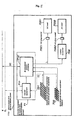
- FIG. 2 is a block diagram exemplifying a configuration of one electric power supplier and demander and an electric power supply and demand control device thereof
- FIG. 3 is an explanation diagram at a time when an electric power supply and demand control device of an electric power supplier and demander performs supply and demand of AC electric power with other electric power supplier and demander in an electric power system of the present invention
- FIG. 4 is an explanation diagram at a time when an electric power supply and demand control device of an electric power supplier and demander performs supply and demand of DC electric power with other electric power supplier and demander in an electric power system of the present invention
- FIG. 1 is an explanation diagram showing an embodiment of an electric power system of the present invention
- FIG. 2 is a block diagram exemplifying a configuration of one electric power supplier and demander and an electric power supply and demand control device thereof
- FIG. 3 is an explanation diagram at a time when an electric power supply and demand control device of an electric power supplier and demander performs supply and demand of AC
- FIG. 5 is an explanation diagram in the case of supplying DC electric power to a load via house wiring of an electric power supplier and demander in an electric power system of the present invention
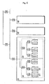
- FIG. 6 is an explanation diagram showing a state where electric power suppliers and demanders are hierarchized in an electric power system of the present invention
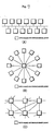
- FIG. 7 (A) is an explanation diagram in the case where electric power suppliers and demanders are connected in a branched shape
- FIG. 7 (B) is an explanation diagram in the case where the electric power suppliers and demanders are connected in a star shape
- FIG. 7 (C) is an explanation diagram in the case where the electric power suppliers and demanders are connected in a net shape
- FIG. 8 is a diagram showing an example of an electric power supplier and demander connected via an electric power supply and demand line which is different from a plurality of other electric power suppliers and demanders
- FIG. 9 is an explanation diagram showing a known electric power system.
- An electric power system 1 shown in FIG. 1 shows only electric power suppliers and demanders of a plurality of electric power suppliers and demanders 11 to 15.
- the respective electric power suppliers and demanders 11 to 15 are mutually connected via an electric power supply and demand line W.
- the electric power supplier and demander 11 is provided with a power generation device 101, an electrical storage device 102, a plurality of loads (electrical devices) 103, and an electric power supply and demand control device 104.
- a plurality of electrical devices 103 are shown by A1, A2, ..., An. Furthermore, in FIG.
- other electric power suppliers and demanders 12, 13, and 14 and other electric power supplier and demander are also provided with a power generation device, an electrical storage device, a plurality of loads (electrical devices), and an electric power supply and demand control device as in the electric power supplier and demander 11; and, each device is connected to branched shape house wiring.
- a power generation device an electrical storage device, a plurality of loads (electrical devices), and an electric power supply and demand control device as in the electric power supplier and demander 11; and, each device is connected to branched shape house wiring.
- all the respective electric power suppliers and demanders or arbitrary electric power suppliers and demanders mount the power generation device 101 and/or the electrical storage device 102 on a pallet of a truck or the like or provide them in a mountable manner, and deliver the power generation device 101 and/or the electrical storage device 102 to other electric power suppliers and demanders as needed; and delivery and receipt of electric power is performed there.
- each of the electric power suppliers and demanders is basically of an independent type, can receive electric power from other electric power supplier and demander when electric power shortage is occurred, and can supply electric power to other electric power supplier and demander when electric power surplus is occurred.
- the electric power supplier and demander 11 is, for example, general houses, multiple dwelling houses, small, medium, and large scale factories, low-rise, medium-rise, and high-rise buildings and the like. Further, a group in which these general houses and multiple dwelling houses are collected can also serve as the electric power supplier and demander 11 of the present invention.
- the power generation device 101 is a solar generator and a DC power supply such as a fuel cell or the like.
- wind generation, biomass generation, or a co-generation system hereinafter, referred to as co-gene in this description
- co-gene such as a gas engine system, a gas turbine system, a fuel cell system, and the like is used as the power generation device 101.
- a wind generation device, a biomass generation device, and the co-gene usually serve as an AC power supply; however, its output is AC/DC converted and can be used as a DC power supply.
- the electrical storage device 102 serves as a DC power supply.
- a flywheel unit can also be used for the power generation device 101.
- the flywheel unit can also be used for the electrical storage device 102.
- an electrical storage device combined by a storage battery and an electric double layer capacitor is also included.
- the load 103 is, for example, a DC device or an AC device, such as an electric light, an air conditioner, a refrigerator, an electromagnetic cooking device, a rice cooker, and the like.
- the electric power supply and demand control device 104 has a control unit 104b which detects a time when electric power surplus is occurred in the electric power supplier and demander 11, for example, a time when the amount of electric power use of the load 103 is reduced and the electrical storage device 102 is near full charge or full charge and can supply electric power generated by the power generation device 101 from an electric power sending and receiving unit 104a to other electric power supplier and demander or the electric power supplier and demander 15, which is connected to the electric power supply and demand line W.
- this supply of electric power is performed by movement of the power generation device 101 or movement of the electrical storage device 102 without using the electric power supply and demand line W.
- the electric power supply and demand control device 104 has the control unit 104b which detects a time when electric power shortage is occurred in the electric power supplier and demander 11, for example, a time when the amount of electric power use of the load 103 is rapidly increased. Then, the electric power supply and demand control device 104 has the electric power sending and receiving unit 104a which receives electric power via the electric power supply and demand control devices of other electric power suppliers and demanders 12, 13, and 14 in which electric power surplus is occurred, the electric power suppliers and demanders being connected to the electric power supply and demand line W, or via an electric power supply and demand control device 153 (to be described later) of the electric power supplier and demander 15 and can drive the load 103 through control of the control unit 104b, or can store in the electrical storage device 102.
- the control unit 104b which detects a time when electric power shortage is occurred in the electric power supplier and demander 11, for example, a time when the amount of electric power use of the load 103 is rapidly increased. Then, the electric power supply and demand control device 104 has
- the electric power supplier and demander 15 includes a power generation device 151, an electrical storage device 152, and the electric power supply and demand control device 153.
- the electric power supplier and demander can include only either the power generation device or the electrical storage device.
- the power generation device 151 is typically a middle scale facility for thermal power, hydraulic power, wind power and the like including a co-gene and a biomass generation facility; and the electrical storage device 152 is typically a secondary battery; however, there is also one which is combined by the storage battery (secondary battery) and the electric double layer capacitor.
- the electric power supplier and demander 15 can supply electric power to the electric power supplier and demander 11 (or, other electric power suppliers and demanders 12 to 14 and the like) as described above via the electric power supply and demand control device 153.
- the electric power supplier and demander 15 can receive supply of electric power from the electric power supplier and demander 11 (or, other electric power suppliers 12 to 14 and the like). Delivery and receipt of electric power in the electric power supplier and demander 15 is also performed via the electric power supply and demand control device; however, as described before, the delivery and receipt of the electric power may be performed by introducing the movable power generation device and electrical storage device of other electric power supplier and demander to the supplier and demander 15.
- Electric power in which the electric power supplier and demander 15 supplies to the electric power supplier and demander 11 and the like is electric power generated by the power generation device 151 or electric power stored in the electrical storage device 152; and electric power in which the electric power supplier and demander 15 is supplied from the electric power supplier and demander 11 and the like is stored in the electrical storage device 152.
- a plurality of power generation devices including a co-gene and a biomass generator in respective power suppliers and demanders can be controlled both automatically and manually on the basis of weather forecast, electric power demand prediction, values based on heat demand prediction, values set by each electric power supplier and demander, or the like in the delivery and receipt of electric power via the electric power supply and demand control device of each electric power supplier and demander (refer to 104c shown in FIG. 2 ).
- each electric power supplier and demander refers to various information from the electric power supply and demand control device in other electric power supplier and demander and can set or change operating conditions of the electric power supply and demand control device of the electric power supplier and demander on the basis of the amount of electric power consumption which is estimated by the electric power supplier and demander (refer to FIG. 2 ).
- control may be made individually for each power generation device, for example, a solar generator is controlled by a conditioner; and a fuel cell and a micro generator are controlled by a power conditioner.
- a control element common to each power generation device is overall controlled by the electric power supply and demand control devices 104 and 105 and a control element specific to an individual power generation device is individually controlled; accordingly, the power generation devices 101 and the same 151 in a handful of the electric power supplier and demander 11 and the same 15 can be optimally controlled as a whole.
- each power generation device such as a known solar generator and a fuel cell only performs control of full output control and system connection by each power conditioner; however, in the present invention, electric power to be supplied and demanded by utilizing a flywheel unit or the like is equalized between output of each power generation device from zero to full output, so that control can be made freely by the electric power supply and demand control devices 104 and 153.
- the above electrical storage devices 102 and 152 typically use a secondary battery independently as a DC power supply.
- the storage battery (secondary battery) and the electric double layer capacitor can be used together for the electrical storage devices 102 and 152.
- control to use depending on electrical storage characteristics and discharge characteristics is controlled by the electric power supply and demand control devices 104 and 153; accordingly, it becomes possible to reasonably respond to diversification of supply and demand mode of electric power in each electric power supplier and demander or diversification of supply mode of electric power in each supplier and demander.
- the storage battery and the electric double layer capacitor are decentrally arranged, for example, the electric double layer capacitor is mounted on the electric power supply and demand control devices 104 and the same 153, and the storage battery is separately disposed or mounted on the electrical device 103; accordingly, a remaining battery level of the electrical storage devices 102 and 152 can be passed to supply according to priority order of electric power demand destinations by way of example.
- various kinds of electrical devices serving as the load 103 provided with the electric power supplier and demander 11 are individually operated by simply individually inputting and cutting off (ON and OFF) electric power.
- a starting preferential order and the size of starting electric power (descending order, or reverse order thereof) of an individual electrical device such as a refrigerator, an air conditioner, a TV, or the like, which constitutes the load 103 in the electric power supplier and demander 11, are set in the electric power supply and demand control device 104; for example, control is made so as to be an order in which a starting order (or a cutting off order) or an order in which an electromotive force is in a descending order; accordingly, it becomes possible to equalize electric power consumption.
- the electric power supply and demand control device 104 can be actuated so that electric power at a time of starting of a device with large starting electric power is supplied from the storage battery provided with the electric double layer capacitor and the flywheel unit.
- control can be made so as not to cause a large pulsation in which current becomes maximum or minimum by the electric power supply and demand control device 104; therefore, it is useful for ensuring more stable operation of the electric power supply and demand control device 104 and the individual electrical device 103. Further, for example, the elimination of a TV standby state and a standby operation of other device can be achieved by changing the electric power supply and demand control device 104 and applied electric power to DC, and therefore, unnecessary electric power consumption can be suppressed.
- the electric power supply and demand control device 104 performs supply and demand of electric power with other electric power suppliers and demanders 12 to 15, the electric power supply and demand control device 104 exchanges information with electric power supply and demand control devices of the other electric power suppliers and demanders and determines supply and demand conditions or the like.
- the supply and demand of electric power among the electric power suppliers and demanders can be performed by AC or can be performed by DC; however, in either case, construction can be made as a local electric power system or construction can be made as a large electric power system in which these electric power systems are combined.
- the electrical storage device 102 of the electric power supplier and demander 11 is large capacity, and when it is high cost, it becomes possible to purvey the loads by electric power to be supplied from other electric power supplier and demander by using small capacity as the electrical storage device 102 (or, not being provided with the electrical storage device 102).
- electric power suppliers and demanders different in time slot electric power consumption pattern for example, houses and business establishments
- those different in electric generation mode for example, a solar generation device, a wind generation device, and a biomass generation device
- FIG. 3 is an explanation diagram showing electric power system in which an electric power supply and demand control device of an electric power supplier and demander performs supply and demand of AC electric power with other electric power supplier and demander.
- Electric power suppliers and demanders 11a, 12a, 13a, 14a, and 15a shown in FIG. 3 correspond to the electric power suppliers and demanders 11, 12, 13, 14, and 15 shown in FIG. 1 .
- An electric power supply and demand control device 51 of the electric power supplier and demander 11a shown in FIG. 3 includes a control device 511 and a bi-directional AC/DC converter 512.
- Control devices of the respective electric power suppliers and demanders are configured so as to be able to perform data communication by a communication line CL, and can exchange supply and demand information in the case of the electric power supply and demand.
- an electric power supply and demand control device 61 of the electric power supplier and demander 15a includes a control device 611, and a bi-directional AC/AC or DC/AC converter 612.
- a control device 611 When the supply and demand of AC electric power is performed between the electric power suppliers and demanders, voltage, current, frequency, and phase have to be matched between both the electric power suppliers and demanders. This matching is performed by the electric power supply and demand control devices 51 and 61.
- the electric power supply and demand control devices 51 and 61 can further include a circuit breaker, a current limiter, a watt-hour meter, and the like.
- the control devices 51 and 61 control discharge; and in the electric power supplier and demander provided with a photovoltaic cell, there is provided with a conditioner which takes out the maximum electric power from a nonlinear electromotive force and adjusts to electric power of the rated characteristics.
- FIG. 4 is an explanation diagram showing electric power system in which an electric power supply and demand control device of an electric power supplier and demander performs supply and demand of DC electric power with other electric power supplier and demander.
- Electric power suppliers and demanders 11b, 12b, 13b, 14b, and 15b shown in FIG. 4 correspond to the electric power suppliers and demanders 11, 12, 13, 14, and 15 shown in FIG. 1 .
- An electric power supply and demand control device 71 of the electric power supplier and demander 15b shown in FIG. 4 includes a control device 711 and a bi-directional DC/DC converter 712.
- Control devices of the respective electric power suppliers and demanders are configured so as to be able to perform data communication by a communication line CL, and can exchange supply and demand information in the case of the electric power supply and demand.
- an electric power supply and demand control device 81 of the electric power supplier and demander 15b includes a control device 811, and a bi-directional DC/DC or DC/AC converter 812. When the supply and demand of electric power in DC is performed between the electric power suppliers and demanders, adjustment of voltage and current is performed.
- the electric power supply and demand control devices 71 and 81 can further include a current limiter, a watt-hour meter, and the like.
- FIG. 5 is an explanation diagram in the case of distributing DC electric power to a load via house wiring of an electric power supplier and demander.
- an electric power supplier and demander 11c shown in FIG. 5 there is specifically shown the power generation device, the electrical storage device, and a plurality of loads in the electric power supplier and demander 11 shown in FIG. 1 .
- an electric power supply and demand control device 71 shown in FIG. 5 is the same as the electric power supply and demand control device 71 shown in FIG. 4 .
- the power generation device is a solar generator 701 by way of example, the electrical storage device is a battery 702, and the plurality of loads are a DC load 7031 and an AC load 7032.
- a bi-directional DC/DC converter 712 performs supply and demand of electric power with the battery 702, the solar generator 701, and the DC load 7031 and performs supply and demand of electric power with the AC load 7032 via a DC/AC converter 706.
- Electric power generated by the solar generator 701 is supplied to the battery 702 and the DC load 7031 via, for example, the bi-directional DC/DC converter 712 or supplied to the AC load 7032 via the DC/AC converter 706.
- the electric power supply and demand control device 71 includes a function which controls charging of the battery 702 and a function which compensates for stable output to the side of house wiring L.
- Electric power from the electric power supply and demand control device 71 is supplied to the DC load 7031 via the house wiring L and the DC outlet 7051.
- the electric power from the electric power supply and demand control device 71 is supplied to the AC load 7032 via the house wiring L, the DC/AC converter 706A, and the AC outlet 7052.
- the DC outlet and the AC outlet are shown by one outlet, respectively; however, the DC outlet and the AC outlet are provided with a plurality of outlets, respectively, and the DC loads and the AC loads can be connected to those outlets.
- the electric power supply and demand control devices 104, 153, and the like in which the respective electric power suppliers and demanders 11, 15, and the like include are served as nodes and the electrical feeder line W among the respective electric power suppliers and demanders 11, 15, and the like is served as a link; accordingly, an electric power network is formed. Therefore, the respective electric power supply and demand control devices 104, 153, and the like are provided with a function which controls exchange of electric power among the respective electric power suppliers and demanders 11, 15, and the like.
- the fundamental function of the electric power supply and demand control devices 104 and 153 is determination of the electric power suppliers and demanders 11, 15, and the like serving as other parties who perform exchange of electric power; determination of whether the exchange of electric power with the other parties is delivery or intake; control of an electric power rate and an electric energy and the like.
- This function controls at a high level that connection is made by communication circuits among the electric power networks; data such as necessary electric power and electric power available for supply for mutual electric power suppliers and demanders, an electric energy and an electric power rate thereof, and these related future estimations are exchanged and processed; and electric power among the respective electric power suppliers and demanders is accommodated with each other.
- the function of the above electric power supply and demand control devices 104 and 153 serve as a circuit breaker and a current limiter by configuring on the basis of, for example, a voltage converter, a current controller, and a switch, which are provided with various control functions; by individually switching communication channels of necessary electric power by control of the converter or the like; and by being based on the size of a transmission current and characteristic analysis of transient phenomenon.
- This allows the electric power supply and demand control devices 104 and 153 to control so that, for example, when an electrical fault is occurred in a certain electric power supplier and demander, each electrical device (load 103), electrical storage device 102, and power generation device 101 of the supplier and demander are not completely cut off, but only a necessary line is cut off and other line can be used without cutting off.
- electric power supplier and demander groups G11, G12, ... show a group at this time (for example, approximately several tens to ten thousands of houses).
- the electric power supplier and demander groups G11, G12, ... are mutually connected via electric power supply and demand control devices S1. Furthermore, higher hierarchy of the electric power supplier and demander groups G11, G12, ... are represented by G21, G22, ..., and further higher hierarchy are represented by G31, G32, G33, .... In this case, although not shown in the drawing, further higher hierarchy than G31, G32, G33, ... are formed.
- the electric power supplier and demander groups G11, G12 ... are set as a "town” unit; G21, G22, ... are set as a "city” unit; and G31, G32, G33, ... are set as a "prefecture" unit.
- the electric power supplier and demander groups G11, G12, ... are mutually connected with other electric power suppliers and demanders by the electric power supply and demand control devices S1; however, the respective higher hierarchies and lower hierarchies are hierarchically connected with each other via electric power supply and demand control devices S2, S3, S4, ....
- the respective electric power suppliers and demanders are connected in a branched shape as shown in FIG. 7(A) .
- the respective electric power suppliers and demanders may be connected in a star shape as shown in FIG. 7(B) or may be connected in a net shape as shown in FIG. 7(C) . Further, the respective electric power suppliers and demanders may be connected in a mode combined with these shapes.
- FIG. 8 is a diagram showing an example of an electric power supplier and demander connected via an electric power supply and demand line which is different from a plurality of other electric power suppliers and demanders.
- a bi-directional DC/DC converter 712 transports electric power among the electric power supply and demand lines W1, W2, and W3 and can intermediate electric power supply and demand among other electric power suppliers and demanders, for example, in the connection mode of the electric power suppliers and demanders as shown in FIG. 7 (C) .
- the transportation of electric power among the electric power supply and demand lines W1 to W3 includes a mode which supplies and demands electric power by moving a movable power generation device and/or a movable electrical storage device.
- an electric power system in which a plurality of electric power suppliers and demanders are configured by being mutually connected by electric power supply and demand control devices, without depending on the known electric power system.
Abstract
Description
- The present invention relates to an electric power system in which a plurality of electric power suppliers and demanders are mutually connected by electric power supply and demand control devices.
- In a known electric power system, as shown in
FIG. 9 , "radial system," in which a large-scale power plant 91 is a top anddemanders 92 are a base, is fundamental. InFIG. 9 , in order to ensure a plurality of transmission systems, a "loop system" is introduced in some part. This kind of electric power system is configured, as a single system, in a broad area (for example, several tens of thousands km2) and large scale (several tens GW). - On the other hand, in recent years, a distributed power generation system of a system collaborative type (for example, refer to Patent Document 1) with solar generation and a fuel cell has been focused. The distributed power generation system of the system collaborative type is usually built in an end region or a local region near the end of the known radiated electric power system, and is premised on interconnection with the electric power system.
- Patent document 1: Japanese Patent Application Laid-Open No.
6-327146 - In the known electric power system structure shown in
FIG. 9 , since transportation of electric power is massively carried out over a long distance, there are a lot of losses; and in electric generation come from reproducible energy such as solar energy and wind power energy, since its reproducible energy is ubiquitous, it is difficult to build a large scale power plant using these energies. - An object of the present invention is to provide an electric power system in which a plurality of electric power suppliers and demanders who demand electric power and also supply electric power are configured by being mutually connected by electric power supply and demand control devices, the electric power system being self-sustainable without depending on the known electric power system. This does not intend that the system of the present invention eliminates coexisting with the known electric power system.
- According to a first configuration of the present invention to solve the above problem, there is provided an electric power system in which a plurality of electric power suppliers and demanders (in the drawings, it is described as Unit to supply and demand electric power) are mutually connected, the electric power supplier and demander being provided with one or a plurality of power generation devices, one or a plurality of electrical storage devices and one or a plurality of electric power consumption devices, and an electric power supply and demand control device.
In the electric power system, each of the electric power supply and demand control devices determines whether or not electric power shortage is occurred or whether or not electric power surplus is occurred in each of the electric power suppliers and demanders provided with the electric power supply and demand control device, receives electric power from other electric power supplier and demander provided with the power generation device and/or the electrical storage device in the case where electric power shortage is occurred in the electric power supplier and demander, controls to deliver electric power to other electric power supplier and demander in the case where electric power surplus is occurred in the electric power supplier and demander, and automatically or manually controls the plurality of the power generation devices in respective power suppliers and demanders on the basis of weather forecast, electric power demand prediction, heat demand prediction, setting values by each supplier and demander, and the like in the delivery and receipt of electric power. - Furthermore, according to a second configuration of an electric power system of the present invention, there is provided an electric power system in which a plurality of electric power suppliers and demanders are mutually connected, the electric power supplier and demander being provided with at least one device selected from one or a plurality of power generation devices, one or a plurality of electrical storage devices and one or a plurality of electric power consumption devices, and an electric power supply and demand control device.
In the electric power system, the plurality of the electric power suppliers and demanders are sectioned into a plurality of groups, and
the electric power supply and demand control device which belongs to each group determines whether or not electric power shortage is occurred or whether or not electric power surplus is occurred in the group, receives electric power from other group to which the electric power supplier and demander provided with the power generation device and/or the electrical storage device belongs in the case where electric power shortage is occurred in the group and, delivers electric power to other group in the case where electric power surplus is occurred in the group, and automatically or manually controls the plurality of the power generation devices in respective power suppliers and demanders of respective groups on the basis of weather forecast, electric power demand prediction, heat demand prediction, and the like in the delivery and receipt of electric power. - Each electric power supplier and demander of the electric power system of the present invention refers to information from the electric power supply and demand control device in other electric power supplier and demander and can set or change operating conditions of the electric power supply and demand control device of the electric power supplier and demander on the basis of the amount of electric power consumption which is estimated by the electric power supplier and demander.
- Furthermore, in the electric power system of the present invention, the electrical storage device in the electric power supplier and demander can use a storage battery and an electric double layer capacitor together.
- In this case, it is preferable to quantitatively comprehend a change in the amount of electrical storage of the storage battery and its charge and discharge transient operation characteristics. This can properly comprehend and analyze charge and discharge phenomena of the storage battery and the electric double layer capacitor.
When the amount of electrical storage of the storage battery is detected, the amount of charge and discharge can be controlled so that its detected value is not to be less than a predetermined lower limit; accordingly, transient response characteristics of the capacitor can be utilized without involving unnecessary consumption of the storage battery.
Further, in the present invention, although not shown in the drawing, a movable power generation device and/or a movable electrical storage device provided by any electric power supplier are/is moved to other electric power supplier and delivery and receipt of necessary electric power can be performed there. - The present invention is an electric power system in which a known electric power system is not provided and each electric power supplier and demander is basically independent. That is, each electric power supplier and demander performs sending and receiving (also referred to as delivery and receipt, hereinafter, same as above) of electric power with other electric power suppliers and demanders when electric power shortage or electric power surplus is occurred. Accordingly, it becomes possible to achieve independence in the whole system in which respective electric power suppliers and demanders are coupled by an electric power network.
In the present invention, a plurality of the electric power suppliers and demanders can be connected to a branched electric power supply and demand line, a beaded electric power supply and demand line, a radiated electric power supply and demand line, a net shaped electric power supply and demand line, or an electric power supply and demand line combined by these lines (hereinafter, the before mentioned each line is also referred to as an electric power supply and demand network in the present invention).
Furthermore, in the present invention, the before mentioned electric power supply and demand control device can perform exchange of supply and demand information of electric power with the electric power supply and demand control devices of other electric power suppliers and demanders via a data communication network.
In the present invention, a plurality of the electric power suppliers and demanders can be connected in DC with each other in order to sufficiently utilize advantage of DC electrical transmission and distribution.
Further, in the present invention, if delivery and receipt of electric power among respective electric power suppliers are made by moving movably provided power generation devices and/or electrical storage devices, connection among respective suppliers and demanders of electric power can be simplified. -
FIG. 1 is an explanation diagram showing an embodiment of an electric power system of the present invention;FIG. 2 is a block diagram exemplifying a configuration of one electric power supplier and demander and an electric power supply and demand control device thereof;FIG. 3 is an explanation diagram at a time when an electric power supply and demand control device of an electric power supplier and demander performs supply and demand of AC electric power with other electric power supplier and demander in an electric power system of the present invention;FIG. 4 is an explanation diagram at a time when an electric power supply and demand control device of an electric power supplier and demander performs supply and demand of DC electric power with other electric power supplier and demander in an electric power system of the present invention;FIG. 5 is an explanation diagram in the case of supplying DC electric power to a load via house wiring of an electric power supplier and demander in an electric power system of the present invention;FIG. 6 is an explanation diagram showing a state where electric power suppliers and demanders are hierarchized in an electric power system of the present invention;FIG. 7 (A) is an explanation diagram in the case where electric power suppliers and demanders are connected in a branched shape;FIG. 7 (B) is an explanation diagram in the case where the electric power suppliers and demanders are connected in a star shape; andFIG. 7 (C) is an explanation diagram in the case where the electric power suppliers and demanders are connected in a net shape;FIG. 8 is a diagram showing an example of an electric power supplier and demander connected via an electric power supply and demand line which is different from a plurality of other electric power suppliers and demanders; andFIG. 9 is an explanation diagram showing a known electric power system. - An
electric power system 1 shown inFIG. 1 shows only electric power suppliers and demanders of a plurality of electric power suppliers and demanders 11 to 15. The respective electric power suppliers anddemanders 11 to 15 are mutually connected via an electric power supply and demand line W.
The electric power supplier anddemander 11 is provided with apower generation device 101, anelectrical storage device 102, a plurality of loads (electrical devices) 103, and an electric power supply anddemand control device 104. Incidentally, a plurality ofelectrical devices 103 are shown by A1, A2, ..., An. Furthermore, inFIG. 1 , other electric power suppliers anddemanders power generation device 101 and/or theelectrical storage device 102 on a pallet of a truck or the like or provide them in a mountable manner, and deliver thepower generation device 101 and/or theelectrical storage device 102 to other electric power suppliers and demanders as needed; and delivery and receipt of electric power is performed there. - In the present invention, the respective electric power suppliers and demanders are loosely coupled thereamong. That is, each of the electric power suppliers and demanders is basically of an independent type, can receive electric power from other electric power supplier and demander when electric power shortage is occurred, and can supply electric power to other electric power supplier and demander when electric power surplus is occurred.
- The electric power supplier and
demander 11 is, for example, general houses, multiple dwelling houses, small, medium, and large scale factories, low-rise, medium-rise, and high-rise buildings and the like. Further, a group in which these general houses and multiple dwelling houses are collected can also serve as the electric power supplier and demander 11 of the present invention.
Typically, thepower generation device 101 is a solar generator and a DC power supply such as a fuel cell or the like. There is also a case where wind generation, biomass generation, or a co-generation system (hereinafter, referred to as co-gene in this description) such as a gas engine system, a gas turbine system, a fuel cell system, and the like is used as thepower generation device 101. A wind generation device, a biomass generation device, and the co-gene usually serve as an AC power supply; however, its output is AC/DC converted and can be used as a DC power supply. In addition, theelectrical storage device 102 serves as a DC power supply.
Further, although not shown in the drawing, a flywheel unit can also be used for thepower generation device 101. The flywheel unit can also be used for theelectrical storage device 102. Furthermore, an electrical storage device combined by a storage battery and an electric double layer capacitor is also included. There is a case where thepower generation device 101 and/or theelectrical storage device 102 are/is mounted on a truck pallet or the like and moved to other electric power supplier, and delivery and receipt of electric power is performed there. Theload 103 is, for example, a DC device or an AC device, such as an electric light, an air conditioner, a refrigerator, an electromagnetic cooking device, a rice cooker, and the like. - As shown in
FIG. 2 , by way of example, the electric power supply anddemand control device 104 has acontrol unit 104b which detects a time when electric power surplus is occurred in the electric power supplier and demander 11, for example, a time when the amount of electric power use of theload 103 is reduced and theelectrical storage device 102 is near full charge or full charge and can supply electric power generated by thepower generation device 101 from an electric power sending and receivingunit 104a to other electric power supplier and demander or the electric power supplier and demander 15, which is connected to the electric power supply and demand line W. There is also a case where this supply of electric power is performed by movement of thepower generation device 101 or movement of theelectrical storage device 102 without using the electric power supply and demand line W. Furthermore, the electric power supply anddemand control device 104 has thecontrol unit 104b which detects a time when electric power shortage is occurred in the electric power supplier and demander 11, for example, a time when the amount of electric power use of theload 103 is rapidly increased. Then, the electric power supply anddemand control device 104 has the electric power sending and receivingunit 104a which receives electric power via the electric power supply and demand control devices of other electric power suppliers anddemanders load 103 through control of thecontrol unit 104b, or can store in theelectrical storage device 102. - The electric power supplier and
demander 15 includes apower generation device 151, anelectrical storage device 152, and the electric power supply anddemand control device 153. Incidentally, the electric power supplier and demander can include only either the power generation device or the electrical storage device. Thepower generation device 151 is typically a middle scale facility for thermal power, hydraulic power, wind power and the like including a co-gene and a biomass generation facility; and theelectrical storage device 152 is typically a secondary battery; however, there is also one which is combined by the storage battery (secondary battery) and the electric double layer capacitor. The electric power supplier anddemander 15 can supply electric power to the electric power supplier and demander 11 (or, other electric power suppliers anddemanders 12 to 14 and the like) as described above via the electric power supply anddemand control device 153. Furthermore, conversely, the electric power supplier anddemander 15 can receive supply of electric power from the electric power supplier and demander 11 (or, otherelectric power suppliers 12 to 14 and the like). Delivery and receipt of electric power in the electric power supplier anddemander 15 is also performed via the electric power supply and demand control device; however, as described before, the delivery and receipt of the electric power may be performed by introducing the movable power generation device and electrical storage device of other electric power supplier and demander to the supplier and demander 15. - Electric power in which the electric power supplier and demander 15 supplies to the electric power supplier and
demander 11 and the like is electric power generated by thepower generation device 151 or electric power stored in theelectrical storage device 152; and electric power in which the electric power supplier anddemander 15 is supplied from the electric power supplier anddemander 11 and the like is stored in theelectrical storage device 152. In the electric power system of the present invention, a plurality of power generation devices including a co-gene and a biomass generator in respective power suppliers and demanders can be controlled both automatically and manually on the basis of weather forecast, electric power demand prediction, values based on heat demand prediction, values set by each electric power supplier and demander, or the like in the delivery and receipt of electric power via the electric power supply and demand control device of each electric power supplier and demander (refer to 104c shown inFIG. 2 ). Further, each electric power supplier and demander refers to various information from the electric power supply and demand control device in other electric power supplier and demander and can set or change operating conditions of the electric power supply and demand control device of the electric power supplier and demander on the basis of the amount of electric power consumption which is estimated by the electric power supplier and demander (refer toFIG. 2 ). - In the above respective
power generation devices 101 and 105, control may be made individually for each power generation device, for example, a solar generator is controlled by a conditioner; and a fuel cell and a micro generator are controlled by a power conditioner. However, in the electric power system of the present invention, a control element common to each power generation device is overall controlled by the electric power supply anddemand control devices 104 and 105 and a control element specific to an individual power generation device is individually controlled; accordingly, thepower generation devices 101 and the same 151 in a handful of the electric power supplier anddemander 11 and the same 15 can be optimally controlled as a whole.
Incidentally, each power generation device such as a known solar generator and a fuel cell only performs control of full output control and system connection by each power conditioner; however, in the present invention, electric power to be supplied and demanded by utilizing a flywheel unit or the like is equalized between output of each power generation device from zero to full output, so that control can be made freely by the electric power supply anddemand control devices - On the other hand, the above
electrical storage devices electrical storage devices - When the above storage battery and the electric double layer capacitor are used together, for example, control to use depending on electrical storage characteristics and discharge characteristics is controlled by the electric power supply and
demand control devices - In this case, the storage battery and the electric double layer capacitor are decentrally arranged, for example, the electric double layer capacitor is mounted on the electric power supply and
demand control devices 104 and the same 153, and the storage battery is separately disposed or mounted on theelectrical device 103; accordingly, a remaining battery level of theelectrical storage devices - Further, formerly, various kinds of electrical devices serving as the
load 103 provided with the electric power supplier anddemander 11 are individually operated by simply individually inputting and cutting off (ON and OFF) electric power.
However, in the electric power system of the present invention, a starting preferential order and the size of starting electric power (descending order, or reverse order thereof) of an individual electrical device such as a refrigerator, an air conditioner, a TV, or the like, which constitutes theload 103 in the electric power supplier anddemander 11, are set in the electric power supply anddemand control device 104; for example, control is made so as to be an order in which a starting order (or a cutting off order) or an order in which an electromotive force is in a descending order; accordingly, it becomes possible to equalize electric power consumption. Furthermore, when an electrical device with large starting electric power is started, the electric power supply anddemand control device 104 can be actuated so that electric power at a time of starting of a device with large starting electric power is supplied from the storage battery provided with the electric double layer capacitor and the flywheel unit. - When electric power consumption can be equalized by controlling priority order at a time of starting as described above, there can be performed dispersion control of an excess current which is easy to flow to the electric power supply and
demand control device 104 and the respectiveelectrical devices 103 at a time of starting of the respectiveelectrical devices 103; therefore, there can be prolonged duration of life of thecontrol device 104 itself, the respective electrical devices, or wiring components such as wiring for connecting therebetween. - In addition, control can be made so as not to cause a large pulsation in which current becomes maximum or minimum by the electric power supply and
demand control device 104; therefore, it is useful for ensuring more stable operation of the electric power supply anddemand control device 104 and the individualelectrical device 103.
Further, for example, the elimination of a TV standby state and a standby operation of other device can be achieved by changing the electric power supply anddemand control device 104 and applied electric power to DC, and therefore, unnecessary electric power consumption can be suppressed. - In the electric power system shown in
FIG. 1 , in the case where the electric power supply anddemand control device 104 performs supply and demand of electric power with other electric power suppliers anddemanders 12 to 15, the electric power supply anddemand control device 104 exchanges information with electric power supply and demand control devices of the other electric power suppliers and demanders and determines supply and demand conditions or the like. - In the electric power system shown in
FIG. 1 , the supply and demand of electric power among the electric power suppliers and demanders can be performed by AC or can be performed by DC; however, in either case, construction can be made as a local electric power system or construction can be made as a large electric power system in which these electric power systems are combined. - In the electric power system shown in
FIG. 1 , although not shown in the drawing, there is also a case where the electric power supplier and demander made up of only loads is connected to the electric power supply and demand line W. Furthermore, in the electric power system shown inFIG. 1 , equalization of supply and demand electric power is performed by mutually connecting many and various electric power suppliers and demanders. - In the case where the
electrical storage device 102 of the electric power supplier anddemander 11 is large capacity, and when it is high cost, it becomes possible to purvey the loads by electric power to be supplied from other electric power supplier and demander by using small capacity as the electrical storage device 102 (or, not being provided with the electrical storage device 102). In this case, it is preferable that electric power suppliers and demanders different in time slot electric power consumption pattern (for example, houses and business establishments) exist together in theelectric power system 1. Furthermore, it is preferable that those different in electric generation mode (for example, a solar generation device, a wind generation device, and a biomass generation device) as the electric power supplier anddemander 15 exist together. -
FIG. 3 is an explanation diagram showing electric power system in which an electric power supply and demand control device of an electric power supplier and demander performs supply and demand of AC electric power with other electric power supplier and demander.
Electric power suppliers anddemanders FIG. 3 correspond to the electric power suppliers anddemanders FIG. 1 . An electric power supply anddemand control device 51 of the electric power supplier anddemander 11a shown inFIG. 3 includes acontrol device 511 and a bi-directional AC/DC converter 512. - Control devices of the respective electric power suppliers and demanders are configured so as to be able to perform data communication by a communication line CL, and can exchange supply and demand information in the case of the electric power supply and demand.
Furthermore, an electric power supply anddemand control device 61 of the electric power supplier and demander 15a includes acontrol device 611, and a bi-directional AC/AC or DC/AC converter 612. When the supply and demand of AC electric power is performed between the electric power suppliers and demanders, voltage, current, frequency, and phase have to be matched between both the electric power suppliers and demanders. This matching is performed by the electric power supply anddemand control devices FIG. 3 , although not shown in the drawing, the electric power supply anddemand control devices control devices -
FIG. 4 is an explanation diagram showing electric power system in which an electric power supply and demand control device of an electric power supplier and demander performs supply and demand of DC electric power with other electric power supplier and demander.
Electric power suppliers anddemanders FIG. 4 correspond to the electric power suppliers anddemanders FIG. 1 . An electric power supply anddemand control device 71 of the electric power supplier anddemander 15b shown inFIG. 4 includes acontrol device 711 and a bi-directional DC/DC converter 712. - Control devices of the respective electric power suppliers and demanders are configured so as to be able to perform data communication by a communication line CL, and can exchange supply and demand information in the case of the electric power supply and demand.
Furthermore, an electric power supply anddemand control device 81 of the electric power supplier anddemander 15b includes a control device 811, and a bi-directional DC/DC or DC/AC converter 812. When the supply and demand of electric power in DC is performed between the electric power suppliers and demanders, adjustment of voltage and current is performed. Incidentally, inFIG. 4 , although not shown in the drawing, the electric power supply anddemand control devices control devices -
FIG. 5 is an explanation diagram in the case of distributing DC electric power to a load via house wiring of an electric power supplier and demander.
In an electric power supplier anddemander 11c shown inFIG. 5 , there is specifically shown the power generation device, the electrical storage device, and a plurality of loads in the electric power supplier anddemander 11 shown inFIG. 1 . Incidentally, an electric power supply anddemand control device 71 shown inFIG. 5 is the same as the electric power supply anddemand control device 71 shown inFIG. 4 . - In the electric power supplier and
demander 11c, the power generation device is asolar generator 701 by way of example, the electrical storage device is abattery 702, and the plurality of loads are aDC load 7031 and anAC load 7032.
In this case, a bi-directional DC/DC converter 712 performs supply and demand of electric power with thebattery 702, thesolar generator 701, and theDC load 7031 and performs supply and demand of electric power with theAC load 7032 via a DC/AC converter 706. - Electric power generated by the
solar generator 701 is supplied to thebattery 702 and theDC load 7031 via, for example, the bi-directional DC/DC converter 712 or supplied to theAC load 7032 via the DC/AC converter 706. - The electric power supply and
demand control device 71 includes a function which controls charging of thebattery 702 and a function which compensates for stable output to the side of house wiring L. - Electric power from the electric power supply and
demand control device 71 is supplied to theDC load 7031 via the house wiring L and theDC outlet 7051. The electric power from the electric power supply anddemand control device 71 is supplied to theAC load 7032 via the house wiring L, the DC/AC converter 706A, and theAC outlet 7052. Incidentally, inFIG. 4 , the DC outlet and the AC outlet are shown by one outlet, respectively; however, the DC outlet and the AC outlet are provided with a plurality of outlets, respectively, and the DC loads and the AC loads can be connected to those outlets. - In the respective electric power suppliers and
demanders demand control devices demanders demanders demand control devices demanders - The fundamental function of the electric power supply and
demand control devices demanders - The function of the above electric power supply and
demand control devices demand control devices electrical storage device 102, andpower generation device 101 of the supplier and demander are not completely cut off, but only a necessary line is cut off and other line can be used without cutting off. - By the way, in the electric power system shown in
FIG. 1 , a properly collected number of groups of the electric power suppliers and demanders can be treated as one electric power supplier and demander. As shown inFIG. 6 , electric power supplier and demander groups G11, G12, ... show a group at this time (for example, approximately several tens to ten thousands of houses). - In
FIG. 6 , the electric power supplier and demander groups G11, G12, ... are mutually connected via electric power supply and demand control devices S1. Furthermore, higher hierarchy of the electric power supplier and demander groups G11, G12, ... are represented by G21, G22, ..., and further higher hierarchy are represented by G31, G32, G33, .... In this case, although not shown in the drawing, further higher hierarchy than G31, G32, G33, ... are formed.
For example, the electric power supplier and demander groups G11, G12 ... are set as a "town" unit; G21, G22, ... are set as a "city" unit; and G31, G32, G33, ... are set as a "prefecture" unit. - In
FIG. 6 , the electric power supplier and demander groups G11, G12, ... are mutually connected with other electric power suppliers and demanders by the electric power supply and demand control devices S1; however, the respective higher hierarchies and lower hierarchies are hierarchically connected with each other via electric power supply and demand control devices S2, S3, S4, .... - In the above embodiments, there is described a case where the respective electric power suppliers and demanders are connected in a branched shape as shown in
FIG. 7(A) . The respective electric power suppliers and demanders may be connected in a star shape as shown inFIG. 7(B) or may be connected in a net shape as shown inFIG. 7(C) . Further, the respective electric power suppliers and demanders may be connected in a mode combined with these shapes. -
FIG. 8 is a diagram showing an example of an electric power supplier and demander connected via an electric power supply and demand line which is different from a plurality of other electric power suppliers and demanders. InFIG. 8 , a bi-directional DC/DC converter 712 transports electric power among the electric power supply and demand lines W1, W2, and W3 and can intermediate electric power supply and demand among other electric power suppliers and demanders, for example, in the connection mode of the electric power suppliers and demanders as shown inFIG. 7 (C) . The transportation of electric power among the electric power supply and demand lines W1 to W3 includes a mode which supplies and demands electric power by moving a movable power generation device and/or a movable electrical storage device. - According to the present invention, there can be provided an electric power system, in which a plurality of electric power suppliers and demanders are configured by being mutually connected by electric power supply and demand control devices, without depending on the known electric power system.
-
-
FIG. 1 is an explanation diagram showing an embodiment of an electric power system of the present invention; -
FIG. 2 is a block diagram exemplifying a configuration of one electric power supplier and demander and an electric power supply and demand control device thereof; -
FIG. 3 is an explanation diagram at a time when an electric power supply and demand control device of an electric power supplier and demander performs supply and demand of AC electric power with other electric power supplier and demander in an electric power system of the present invention; -
FIG. 4 is an explanation diagram at a time when an electric power supply and demand control device of an electric power supplier and demander performs supply and demand of DC electric power with other electric power supplier and demander in an electric power system of the present invention; -
FIG. 5 is an explanation diagram in the case of supplying DC electric power to a load via house wiring of an electric power supplier and demander in an electric power system of the present invention; -
FIG. 6 is an explanation diagram showing a state where electric power suppliers and demanders are hierarchized in an electric power system of the present invention; -
FIG. 7(A) is an explanation diagram in the case where electric power suppliers and demanders are connected in a branched shape;FIG. 7 (B) is an explanation diagram in the case where the electric power suppliers and demanders are connected in a star shape; andFIG. 7 (C) is an explanation diagram in the case where the electric power suppliers and demanders are connected in a net shape; -
FIG. 8 is a diagram showing an example of an electric power supplier and demander connected via an electric power supply and demand line which is different from a plurality of other electric power suppliers and demanders; and -
FIG. 9 is an explanation diagram showing a known electric power system. -
- 1 Electric power system
- 11, 12, 13, 14, 11a, 12a, 13a, 14a, 11b, 12b, 13b, 14b, 11c,
- 11d, 12c, 13c, 14c, 15, 15a, and 15b Electric power supplier and demander (Unit to supply and demand electric power)
- 51, 61, 71, 81, 104, and 153 Electric power supply and demand control device
- 101 and 151 Power generation device
- 102 and 152 Electrical storage device
- 103 Load
- 511, 611, 711, and 811 Control device
- 512 Bi-directional AC/DC converter
- 612 Bi-directional AC/AC or DC/AC converter
- 706 DC/AC converter
- 712 Bi-directional DC/DC converter
- 812 Bi-directional DC/DC or DC/AC converter
- CC Communication line
- CL Communication line
- L House wiring
- W, W1, W2, and W3 Electric power supply and demand line
Claims (12)
- An electric power system in which a plurality of electric power suppliers and demanders are mutually connected, the electric power supplier and demander being provided with one or a plurality of power generation devices, one or a plurality of electrical storage devices and one or a plurality of electric power consumption devices, and an electric power supply and demand control device,
wherein each of the electric power supply and demand control devices determines whether or not electric power shortage is occurred or whether or not electric power surplus is occurred in each of the electric power suppliers and demanders provided with said electric power supply and demand control device, receives electric power from other electric power supplier and demander provided with the power generation device and/or the electrical storage device in the case where electric power shortage is occurred in the electric power supplier and demander, controls to deliver electric power to other electric power supplier and demander in the case where electric power surplus is occurred in the electric power supplier and demander, and automatically or manually controls the plurality of the power generation devices including a co-gene in respective power suppliers and demanders on the basis of weather forecast, electric power demand prediction, heat demand prediction, setting values by each supplier and demander, and the like in the delivery and receipt of electric power. - The electric power system according to claim 1,
wherein each of the electric power suppliers and demanders refers to information from the electric power supply and demand control device in other electric power supplier and demander, and sets or changes operating conditions of the electric power supply and demand control device of the electric power supplier and demander on the basis of the amount of electric power consumption which is estimated by the electric power supplier and demander. - The electric power system according to claim 1 or 2,
wherein the power generation device of each of the electric power supplier and demander is such that a control element common to each power generation device is overall controlled, and a control element specific to an individual power generation device is individually controlled. - The electric power system according to claim 1,
wherein the delivery and receipt of electric power is performed by moving a movable power generation device and/or a movable electrical storage device to other electric power supplier and demander. - An electric power system in which a plurality of electric power suppliers and demanders are mutually connected, the electric power supplier and demander being provided with at least one device selected from one or a plurality of power generation devices, one or a plurality of electrical storage devices and one or a plurality of electric power consumption devices, and an electric power supply and demand control device,
wherein the plurality of electric power suppliers and demanders are sectioned into a plurality of groups, and
the electric power supply and demand control device which belongs to each group determines whether or not electric power shortage is occurred or whether or not electric power surplus is occurred in the group, receives electric power from other group to which the electric power supplier and demander provided with the power generation device and/or the electrical storage device belongs in the case where electric power shortage is occurred in the group, and delivers electric power to other group in the case where electric power surplus is occurred in the group, and automatically or manually controls the plurality of the power generation devices in respective power suppliers and demanders of respective groups depending on weather forecast, electric power demand prediction, heat demand prediction, and the like in the delivery and receipt of electric power. - The electric power system according to claim 5,
wherein each of the electric power suppliers and demanders refers to information from the electric power supply and demand control device in other electric power supplier and demander, and sets or changes operating conditions of the electric power supply and demand control device of the electric power supplier and demander on the basis of the amount of electric power consumption which is estimated by the electric power supplier and demander. - The electric power system according to claim 5 or 6,
wherein the power generation device of each electric power supplier and demander is such that a control element common to each power generation device is overall controlled, and a control element specific to an individual power generation device is individually controlled. - The electric power system according to any one of claims 1 to 7,
wherein the power generation device of each of the electric power suppliers and demanders includes at least a co-generation system and a biomass generator. - The electric power system according to any one of claims 1 to 8,
wherein the electrical storage device in the electric power supplier and demander uses a storage battery and an electric double layer capacitor together. - The electric power system according to any one of claims 1 to 9,
wherein the plurality of electric power suppliers and demanders are connected to a branched electric power supply and demand line, a beaded electric power supply and demand line, a radiated electric power supply and demand line, a net shaped electric power supply and demand line, or an electric power supply and demand line combined with these lines. - The electric power system according to any one of claims 1 to 10,
wherein the electric power supply and demand control device performs exchange of supply and demand information of electric power with the electric power supply and demand control devices of other electric power suppliers and demanders via a data communication network. - The electric power system according to any one of claims 1 to 11,
wherein the plurality of electric power suppliers and demanders are mutually connected in DC.
Applications Claiming Priority (1)
| Application Number | Priority Date | Filing Date | Title |
|---|---|---|---|
| PCT/JP2006/320556 WO2008047400A1 (en) | 2006-10-16 | 2006-10-16 | Electric power system |
Publications (3)
| Publication Number | Publication Date |
|---|---|
| EP2075891A1 true EP2075891A1 (en) | 2009-07-01 |
| EP2075891A4 EP2075891A4 (en) | 2012-03-28 |
| EP2075891B1 EP2075891B1 (en) | 2014-01-01 |
Family
ID=39313661
Family Applications (1)
| Application Number | Title | Priority Date | Filing Date |
|---|---|---|---|
| EP20060811825 Revoked EP2075891B1 (en) | 2006-10-16 | 2006-10-16 | Electric power system |
Country Status (7)
| Country | Link |
|---|---|
| US (1) | US8415827B2 (en) |
| EP (1) | EP2075891B1 (en) |
| JP (1) | JPWO2008047400A1 (en) |
| CN (1) | CN101529687A (en) |
| BR (1) | BRPI0622066A2 (en) |
| ES (1) | ES2446925T3 (en) |
| WO (1) | WO2008047400A1 (en) |
Cited By (12)
| Publication number | Priority date | Publication date | Assignee | Title |
|---|---|---|---|---|
| ITMI20090711A1 (en) * | 2009-04-27 | 2010-10-28 | Sandra Magnani | EQUIPMENT FOR THE MANAGEMENT OF ELECTRIC ENERGY PURCHASED / PRODUCED BY A USER / MANUFACTURER |
| WO2011101687A3 (en) * | 2010-02-19 | 2012-03-08 | Building Research Establishment Ltd | Powering of devices |
| EP2477297A1 (en) * | 2009-09-10 | 2012-07-18 | Rikiya Abe | Multi-terminal power conversion device, multi-terminal power transfer device, and power network system |
| EP2498365A1 (en) * | 2009-11-06 | 2012-09-12 | Panasonic Corporation | Electric power interchange system |
| EP2408083A4 (en) * | 2009-03-12 | 2014-03-05 | Vpec Inc | Autonomous distributed ac power system |
| EP2293410A3 (en) * | 2009-09-04 | 2014-04-30 | Robert Bosch GmbH | Energy control device for an energy network with a control unit for controlling an energy flow between the energy generator, the energy storage unit, the load unit and/or the energy network |
| EP2293409A3 (en) * | 2009-09-04 | 2014-04-30 | Robert Bosch GmbH | Isolated unit of an isolated energy network for communicating energy requests to a further isolated unit |
| DE102015109967A1 (en) * | 2015-06-22 | 2016-12-22 | Gip Ag | Device and method for bidirectionally connecting two power grids |
| EP3093951A4 (en) * | 2014-01-08 | 2017-09-20 | Sony Corporation | Power control device and power control method |
| EP2587624A4 (en) * | 2010-10-15 | 2018-01-24 | Panasonic Intellectual Property Management Co., Ltd. | Power management system |
| EP3379678A1 (en) * | 2017-03-23 | 2018-09-26 | Solaredge Technologies Ltd. | Balancer circuit |
| FR3090227A1 (en) * | 2018-12-14 | 2020-06-19 | Dimensions | Distributed, shared and operable energy production and distribution system |
Families Citing this family (38)
| Publication number | Priority date | Publication date | Assignee | Title |
|---|---|---|---|---|
| JP2010041133A (en) * | 2008-07-31 | 2010-02-18 | Panasonic Electric Works Co Ltd | Information outlet apparatus |
| EP2911262A3 (en) * | 2009-11-06 | 2015-12-16 | Panasonic Intellectual Property Management Co., Ltd. | Power distribution system |
| JP2011101534A (en) * | 2009-11-06 | 2011-05-19 | Panasonic Electric Works Co Ltd | Electric power interchange system |
| JPWO2011086806A1 (en) * | 2010-01-18 | 2013-05-16 | ローム株式会社 | Power system |
| US20110278921A1 (en) * | 2010-05-11 | 2011-11-17 | Erik Jon Fretheim | Adaptive Power Bus |
| CN102884700B (en) * | 2010-07-28 | 2016-01-20 | 松下知识产权经营株式会社 | The control method of the control device of electric power supply system, electric power supply system, the method for operation of electric power supply system and electric power supply system |
| JP5604223B2 (en) * | 2010-08-23 | 2014-10-08 | ローム株式会社 | Power system |
| CN102427272A (en) * | 2010-11-25 | 2012-04-25 | 上海市电力公司 | Battery energy storage monitoring scheduling system and control method thereof |
| JP5580183B2 (en) * | 2010-12-13 | 2014-08-27 | パナソニック株式会社 | Power control apparatus and power control system using the same |
| EP2501011A3 (en) * | 2011-03-18 | 2013-03-27 | Thomson Licensing | Centralised management of the power supply of a plurality of local power grids |
| JP5899640B2 (en) * | 2011-03-30 | 2016-04-06 | ソニー株式会社 | Power management apparatus, power management method, and power management system |
| JP2012249458A (en) * | 2011-05-30 | 2012-12-13 | Sony Corp | Power supply apparatus and power supply control method |
| JP5802463B2 (en) * | 2011-07-22 | 2015-10-28 | 株式会社東芝 | Electric quantity adjusting device, electric quantity adjusting method, electric quantity adjusting program, and power supply system |
| JP5818602B2 (en) * | 2011-09-20 | 2015-11-18 | 三菱重工メカトロシステムズ株式会社 | Mechanical parking apparatus and power supply method for mechanical parking apparatus |
| JP2013090344A (en) * | 2011-10-13 | 2013-05-13 | Hitachi Ltd | Power interchange method and power interchange device |
| KR20140101855A (en) * | 2012-02-14 | 2014-08-20 | 도시바 미쓰비시덴키 산교시스템 가부시키가이샤 | Power equalisation device |
| NO334364B1 (en) * | 2012-05-03 | 2014-02-17 | Kongsberg Maritime As | PREDICTIVE CONTROL SYSTEM. |
| CN102684183B (en) * | 2012-05-08 | 2014-08-20 | 吕遥 | DC LAN (Direct Current Local Area Network)-based distributed power generation system and control method |
| JP5903661B2 (en) * | 2012-05-22 | 2016-04-13 | パナソニックIpマネジメント株式会社 | Grid interconnection device |
| JP5917292B2 (en) * | 2012-05-28 | 2016-05-11 | 株式会社日立製作所 | Power management apparatus, power management system, and power management method |
| JP5834227B2 (en) * | 2012-11-26 | 2015-12-16 | パナソニックIpマネジメント株式会社 | Storage battery control method and storage battery control system |
| JP6140521B2 (en) * | 2013-05-10 | 2017-05-31 | 学校法人慶應義塾 | Power network system |
| JPWO2014185035A1 (en) * | 2013-05-17 | 2017-02-23 | 日本電気株式会社 | Power network system and power adjustment apparatus and method |
| JP6163040B2 (en) * | 2013-07-31 | 2017-07-12 | 積水化学工業株式会社 | Power management apparatus, power management method and program |
| US10326270B2 (en) | 2014-08-05 | 2019-06-18 | Sony Corporation | DC power transmission device, DC power reception device, and DC power transmission system |
| US10683815B2 (en) | 2014-10-28 | 2020-06-16 | Colorado State University Research Foundation | Gaseous fuel consuming engine controlling systems |
| CN104319822B (en) * | 2014-11-19 | 2016-08-17 | 国网上海市电力公司 | A kind of across grid power peak modulation capacity dispatching method and equipment |
| US9964978B2 (en) | 2015-04-14 | 2018-05-08 | Princeton Power Systems, Inc. | Control systems for microgrid power inverter and methods thereof |
| US9917322B2 (en) * | 2015-07-01 | 2018-03-13 | The Boeing Company | Electrical power distribution system and method for a grid-tied reversible solid oxide fuel cell system |
| JP6365686B2 (en) * | 2015-07-22 | 2018-08-01 | Jfeスチール株式会社 | Power system |
| CN105226639B (en) * | 2015-09-07 | 2018-07-03 | 中国东方电气集团有限公司 | Based on the micro-grid system designing scheme and test platform that the equivalent electricity price of system is minimum |
| US10199833B1 (en) * | 2016-03-04 | 2019-02-05 | Seagate Technology Llc | Power balancing |
| JP7200908B2 (en) * | 2019-10-30 | 2023-01-10 | トヨタ自動車株式会社 | Notification control device, moving body, and electric power system |
| US11340677B2 (en) | 2020-01-31 | 2022-05-24 | Seagate Technology Llc | Data storage device power monitoring |
| TWI732480B (en) * | 2020-03-03 | 2021-07-01 | 力能科技有限公司 | Electric power generation cycle application storage system |
| US11397623B2 (en) | 2020-03-19 | 2022-07-26 | Seagate Technology Llc | Data storage device load sharing |
| KR102229900B1 (en) * | 2020-04-13 | 2021-03-22 | 주식회사 에이투엠 | Integrated data service platform apparatus based on bigdata in multiplex microgrid circumstance |
| CN111564869B (en) * | 2020-06-11 | 2021-08-31 | 国网山东省电力公司电力科学研究院 | Method and system for evaluating AGC performance of generator set |
Citations (9)
| Publication number | Priority date | Publication date | Assignee | Title |
|---|---|---|---|---|
| JP2003047155A (en) * | 2001-07-31 | 2003-02-14 | Osaka Gas Co Ltd | Power feeding method |
| WO2003056671A2 (en) * | 2001-12-28 | 2003-07-10 | Abb Research Ltd. | On-line control of distributed resources with different dispatching levels |
| JP2004015882A (en) * | 2002-06-05 | 2004-01-15 | Mitsubishi Heavy Ind Ltd | Distributed power supply system and method and operation program |
| US20040051387A1 (en) * | 2002-09-17 | 2004-03-18 | Lasseter Robert H. | Control of small distributed energy resources |
| US20040111226A1 (en) * | 2002-12-09 | 2004-06-10 | Brewster David B. | Aggregation of distributed generation resources |
| US6882904B1 (en) * | 2000-12-29 | 2005-04-19 | Abb Technology Ag | Communication and control network for distributed power resource units |
| JP2006174540A (en) * | 2004-12-13 | 2006-06-29 | Takenaka Komuten Co Ltd | Autonomous distributed control type electric storage system |
| JP2006288162A (en) * | 2005-04-05 | 2006-10-19 | Inst Of Research & Innovation | Control method for electric energy interchange in power system |
| WO2006138592A2 (en) * | 2005-06-17 | 2006-12-28 | Optimal Licensing Corporation | Fast acting distributed power system for trasmission and distribution system load using energy storage units |
Family Cites Families (11)
| Publication number | Priority date | Publication date | Assignee | Title |
|---|---|---|---|---|
| JPH0213231A (en) * | 1988-06-30 | 1990-01-17 | Toyo Densan Kk | Synchronous operation controller for plural ac generator mechanisms for vehicle |
| JP2952334B2 (en) * | 1990-07-16 | 1999-09-27 | 旭化成工業株式会社 | Laminated sheet for packaging |
| JP3356022B2 (en) * | 1997-09-19 | 2002-12-09 | 株式会社日立製作所 | Power interconnection interchange command device |
| JP2000333367A (en) * | 1999-05-19 | 2000-11-30 | Toshiba Corp | Thermoelectric consumption predicting system |
| JP4734769B2 (en) * | 2001-06-04 | 2011-07-27 | 株式会社Ihi | Cogeneration plant operation method and apparatus |
| JP3970634B2 (en) * | 2002-02-22 | 2007-09-05 | 東芝プラントシステム株式会社 | Connecting device for mobile power supply |
| JP2003304635A (en) * | 2002-04-05 | 2003-10-24 | Kazuhiko Yamamoto | Method for employing natural energy as electric power |
| JP2003324850A (en) * | 2002-04-26 | 2003-11-14 | Nippon Telegr & Teleph Corp <Ntt> | Power demand/supply adjusting system and customer controller |
| WO2004023625A1 (en) * | 2002-09-04 | 2004-03-18 | Hitachi, Ltd. | Power supply system and power supply method upon interruption of electric service |
| EP1554642A1 (en) * | 2002-10-15 | 2005-07-20 | Powerdsine Ltd. | Direct current power pooling |
| US7400062B2 (en) * | 2002-10-15 | 2008-07-15 | Microsemi Corp. - Analog Mixed Signal Group Ltd. | Rack level power management |
-
2006
- 2006-10-16 CN CN200680056126A patent/CN101529687A/en active Pending
- 2006-10-16 WO PCT/JP2006/320556 patent/WO2008047400A1/en active Application Filing
- 2006-10-16 ES ES06811825T patent/ES2446925T3/en active Active
- 2006-10-16 BR BRPI0622066-5A2A patent/BRPI0622066A2/en not_active IP Right Cessation
- 2006-10-16 US US12/443,256 patent/US8415827B2/en active Active
- 2006-10-16 EP EP20060811825 patent/EP2075891B1/en not_active Revoked
- 2006-10-16 JP JP2008539620A patent/JPWO2008047400A1/en active Pending
Patent Citations (9)
| Publication number | Priority date | Publication date | Assignee | Title |
|---|---|---|---|---|
| US6882904B1 (en) * | 2000-12-29 | 2005-04-19 | Abb Technology Ag | Communication and control network for distributed power resource units |
| JP2003047155A (en) * | 2001-07-31 | 2003-02-14 | Osaka Gas Co Ltd | Power feeding method |
| WO2003056671A2 (en) * | 2001-12-28 | 2003-07-10 | Abb Research Ltd. | On-line control of distributed resources with different dispatching levels |
| JP2004015882A (en) * | 2002-06-05 | 2004-01-15 | Mitsubishi Heavy Ind Ltd | Distributed power supply system and method and operation program |
| US20040051387A1 (en) * | 2002-09-17 | 2004-03-18 | Lasseter Robert H. | Control of small distributed energy resources |
| US20040111226A1 (en) * | 2002-12-09 | 2004-06-10 | Brewster David B. | Aggregation of distributed generation resources |
| JP2006174540A (en) * | 2004-12-13 | 2006-06-29 | Takenaka Komuten Co Ltd | Autonomous distributed control type electric storage system |
| JP2006288162A (en) * | 2005-04-05 | 2006-10-19 | Inst Of Research & Innovation | Control method for electric energy interchange in power system |
| WO2006138592A2 (en) * | 2005-06-17 | 2006-12-28 | Optimal Licensing Corporation | Fast acting distributed power system for trasmission and distribution system load using energy storage units |
Non-Patent Citations (1)
| Title |
|---|
| See also references of WO2008047400A1 * |
Cited By (25)
| Publication number | Priority date | Publication date | Assignee | Title |
|---|---|---|---|---|
| EP2408083A4 (en) * | 2009-03-12 | 2014-03-05 | Vpec Inc | Autonomous distributed ac power system |
| EP2246955A3 (en) * | 2009-04-27 | 2012-05-09 | Sandra Magnani | Apparatus for actuating and managing electric nets and electric energy acquired/produced by a user/producer |
| ITMI20090711A1 (en) * | 2009-04-27 | 2010-10-28 | Sandra Magnani | EQUIPMENT FOR THE MANAGEMENT OF ELECTRIC ENERGY PURCHASED / PRODUCED BY A USER / MANUFACTURER |
| US8803362B2 (en) | 2009-09-04 | 2014-08-12 | Voltwerk Electronics Gmbh | Standalone unit of a standalone power grid for communicating energy requests with another standalone unit |
| EP3267549A1 (en) * | 2009-09-04 | 2018-01-10 | Robert Bosch GmbH | Isolated unit of an isolated energy network for communicating energy requests with a further isolated unit |
| EP3182549A1 (en) * | 2009-09-04 | 2017-06-21 | Robert Bosch GmbH | Sol-ion i: single system |
| EP2293410B1 (en) | 2009-09-04 | 2017-02-22 | Robert Bosch GmbH | Energy control device for an energy network with a control unit for controlling an energy flow between the energy generator, the energy storage unit, the load unit and/or the energy network |
| EP2293410A3 (en) * | 2009-09-04 | 2014-04-30 | Robert Bosch GmbH | Energy control device for an energy network with a control unit for controlling an energy flow between the energy generator, the energy storage unit, the load unit and/or the energy network |
| EP2293409A3 (en) * | 2009-09-04 | 2014-04-30 | Robert Bosch GmbH | Isolated unit of an isolated energy network for communicating energy requests to a further isolated unit |
| US9013902B2 (en) | 2009-09-10 | 2015-04-21 | The University Of Tokyo | Multi-terminal power conversion device, multi-terminal power transfer device, and power network system |
| EP2477297A4 (en) * | 2009-09-10 | 2015-04-01 | Univ Tokyo | Multi-terminal power conversion device, multi-terminal power transfer device, and power network system |
| EP2477297A1 (en) * | 2009-09-10 | 2012-07-18 | Rikiya Abe | Multi-terminal power conversion device, multi-terminal power transfer device, and power network system |
| EP2498365A4 (en) * | 2009-11-06 | 2014-08-06 | Panasonic Corp | Electric power interchange system |
| EP2498365A1 (en) * | 2009-11-06 | 2012-09-12 | Panasonic Corporation | Electric power interchange system |
| US20130154367A1 (en) * | 2010-02-19 | 2013-06-20 | The University Of Strathclyde | Powering of devices |
| WO2011101687A3 (en) * | 2010-02-19 | 2012-03-08 | Building Research Establishment Ltd | Powering of devices |
| EP2587624A4 (en) * | 2010-10-15 | 2018-01-24 | Panasonic Intellectual Property Management Co., Ltd. | Power management system |
| EP3093951A4 (en) * | 2014-01-08 | 2017-09-20 | Sony Corporation | Power control device and power control method |
| DE102015109967A1 (en) * | 2015-06-22 | 2016-12-22 | Gip Ag | Device and method for bidirectionally connecting two power grids |
| EP3379678A1 (en) * | 2017-03-23 | 2018-09-26 | Solaredge Technologies Ltd. | Balancer circuit |
| US10700618B2 (en) | 2017-03-23 | 2020-06-30 | Solaredge Technologies Ltd. | Balancer circuit that provides power from DC-to-DC converter and from DC-to-AC converter to at least one load |
| US11463018B2 (en) | 2017-03-23 | 2022-10-04 | Solaredge Technologies Ltd. | AC to AC converter |
| EP3379678B1 (en) | 2017-03-23 | 2022-11-02 | Solaredge Technologies Ltd. | Balancer circuit |
| US11949344B2 (en) | 2017-03-23 | 2024-04-02 | Solaredge Technologies Ltd. | DC-to-DC power converter |
| FR3090227A1 (en) * | 2018-12-14 | 2020-06-19 | Dimensions | Distributed, shared and operable energy production and distribution system |
Also Published As
| Publication number | Publication date |
|---|---|
| CN101529687A (en) | 2009-09-09 |
| BRPI0622066A2 (en) | 2014-05-27 |
| US8415827B2 (en) | 2013-04-09 |
| EP2075891A4 (en) | 2012-03-28 |
| EP2075891B1 (en) | 2014-01-01 |
| US20100001585A1 (en) | 2010-01-07 |
| WO2008047400A1 (en) | 2008-04-24 |
| JPWO2008047400A1 (en) | 2010-02-18 |
| ES2446925T3 (en) | 2014-03-10 |
Similar Documents
| Publication | Publication Date | Title |
|---|---|---|
| EP2075891B1 (en) | Electric power system | |
| US8401708B2 (en) | Electric power system | |
| JP5100009B2 (en) | Power system | |
| US8970176B2 (en) | DC micro-grid | |
| US7612466B2 (en) | System and method for coordinated control and utilization of local storage and generation, with a power grid | |
| US10873099B1 (en) | Storage system controller | |
| CN102386635B (en) | The system of the distribution that inverter VAR supports and method | |
| US20130088084A1 (en) | Networklized DC Power System | |
| CN105379048B (en) | Power inverter, power conversion system and power transferring method | |
| CN103229380A (en) | Method and system facilitating control strategy for power electronics interface of distributed generation resources | |
| CN103733474B (en) | For generating, storing and supply by the system of the electric energy of modularization DC makers generation and the correlation technique for managing the system | |
| CN101572437A (en) | Power management system | |
| US11196291B2 (en) | Data center with backup power system | |
| KR101176100B1 (en) | Power control system in micro-grid | |
| CN104604123A (en) | Management system, management method, control device, and photovoltaic cell device | |
| CN104541294A (en) | Method and apparatus for spatiotemporal control of the electric power draw of a telecommunication network on the basis of states of the power supply system | |
| KR101819277B1 (en) | Energy Storage System | |
| JP5475387B2 (en) | Power supply optimization device for power supply system | |
| JPH1155856A (en) | Electric power system operation system and terminal equipment for consumer used in the system | |
| KR102421893B1 (en) | Energy storage system | |
| CN209994117U (en) | Energy storage system | |
| CN105529746A (en) | Flexible power distribution system | |
| CN217693525U (en) | Unattended region monitoring device and system | |
| KR20120116253A (en) | Eco-friendly electric vehicle charging system | |
| JP2023095009A (en) | Power system and operation method therefor |
Legal Events
| Date | Code | Title | Description |
|---|---|---|---|
| PUAI | Public reference made under article 153(3) epc to a published international application that has entered the european phase |
Free format text: ORIGINAL CODE: 0009012 |
|
| 17P | Request for examination filed |
Effective date: 20090408 |
|
| AK | Designated contracting states |
Kind code of ref document: A1 Designated state(s): AT BE BG CH CY CZ DE DK EE ES FI FR GB GR HU IE IS IT LI LT LU LV MC NL PL PT RO SE SI SK TR |
|
| AX | Request for extension of the european patent |
Extension state: AL BA HR MK RS |
|
| RIC1 | Information provided on ipc code assigned before grant |
Ipc: H02J 3/32 20060101ALI20120216BHEP Ipc: H02J 1/00 20060101ALI20120216BHEP Ipc: H02J 3/46 20060101AFI20120216BHEP |
|
| A4 | Supplementary search report drawn up and despatched |
Effective date: 20120224 |
|
| DAX | Request for extension of the european patent (deleted) | ||
| 17Q | First examination report despatched |
Effective date: 20121130 |
|
| GRAP | Despatch of communication of intention to grant a patent |
Free format text: ORIGINAL CODE: EPIDOSNIGR1 |
|
| INTG | Intention to grant announced |
Effective date: 20130827 |
|
| GRAS | Grant fee paid |
Free format text: ORIGINAL CODE: EPIDOSNIGR3 |
|
| GRAA | (expected) grant |
Free format text: ORIGINAL CODE: 0009210 |
|
| AK | Designated contracting states |
Kind code of ref document: B1 Designated state(s): AT BE BG CH CY CZ DE DK EE ES FI FR GB GR HU IE IS IT LI LT LU LV MC NL PL PT RO SE SI SK TR |
|
| REG | Reference to a national code |
Ref country code: GB Ref legal event code: FG4D |
|
| REG | Reference to a national code |
Ref country code: CH Ref legal event code: EP |
|
| REG | Reference to a national code |
Ref country code: IE Ref legal event code: FG4D |
|
| REG | Reference to a national code |
Ref country code: DE Ref legal event code: R096 Ref document number: 602006039905 Country of ref document: DE Effective date: 20140213 |
|
| REG | Reference to a national code |
Ref country code: AT Ref legal event code: REF Ref document number: 647967 Country of ref document: AT Kind code of ref document: T Effective date: 20140215 |
|
| REG | Reference to a national code |
Ref country code: ES Ref legal event code: FG2A Ref document number: 2446925 Country of ref document: ES Kind code of ref document: T3 Effective date: 20140310 |
|
| REG | Reference to a national code |
Ref country code: NL Ref legal event code: VDEP Effective date: 20140101 |
|
| REG | Reference to a national code |
Ref country code: AT Ref legal event code: MK05 Ref document number: 647967 Country of ref document: AT Kind code of ref document: T Effective date: 20140101 |
|
| REG | Reference to a national code |
Ref country code: LT Ref legal event code: MG4D |
|
| PG25 | Lapsed in a contracting state [announced via postgrant information from national office to epo] |
Ref country code: LT Free format text: LAPSE BECAUSE OF FAILURE TO SUBMIT A TRANSLATION OF THE DESCRIPTION OR TO PAY THE FEE WITHIN THE PRESCRIBED TIME-LIMIT Effective date: 20140101 Ref country code: IS Free format text: LAPSE BECAUSE OF FAILURE TO SUBMIT A TRANSLATION OF THE DESCRIPTION OR TO PAY THE FEE WITHIN THE PRESCRIBED TIME-LIMIT Effective date: 20140501 |
|
| PG25 | Lapsed in a contracting state [announced via postgrant information from national office to epo] |
Ref country code: SE Free format text: LAPSE BECAUSE OF FAILURE TO SUBMIT A TRANSLATION OF THE DESCRIPTION OR TO PAY THE FEE WITHIN THE PRESCRIBED TIME-LIMIT Effective date: 20140101 Ref country code: FI Free format text: LAPSE BECAUSE OF FAILURE TO SUBMIT A TRANSLATION OF THE DESCRIPTION OR TO PAY THE FEE WITHIN THE PRESCRIBED TIME-LIMIT Effective date: 20140101 Ref country code: CY Free format text: LAPSE BECAUSE OF FAILURE TO SUBMIT A TRANSLATION OF THE DESCRIPTION OR TO PAY THE FEE WITHIN THE PRESCRIBED TIME-LIMIT Effective date: 20140101 Ref country code: NL Free format text: LAPSE BECAUSE OF FAILURE TO SUBMIT A TRANSLATION OF THE DESCRIPTION OR TO PAY THE FEE WITHIN THE PRESCRIBED TIME-LIMIT Effective date: 20140101 Ref country code: PT Free format text: LAPSE BECAUSE OF FAILURE TO SUBMIT A TRANSLATION OF THE DESCRIPTION OR TO PAY THE FEE WITHIN THE PRESCRIBED TIME-LIMIT Effective date: 20140502 Ref country code: AT Free format text: LAPSE BECAUSE OF FAILURE TO SUBMIT A TRANSLATION OF THE DESCRIPTION OR TO PAY THE FEE WITHIN THE PRESCRIBED TIME-LIMIT Effective date: 20140101 |
|
| REG | Reference to a national code |
Ref country code: DE Ref legal event code: R026 Ref document number: 602006039905 Country of ref document: DE |
|
| PG25 | Lapsed in a contracting state [announced via postgrant information from national office to epo] |
Ref country code: LV Free format text: LAPSE BECAUSE OF FAILURE TO SUBMIT A TRANSLATION OF THE DESCRIPTION OR TO PAY THE FEE WITHIN THE PRESCRIBED TIME-LIMIT Effective date: 20140101 Ref country code: BE Free format text: LAPSE BECAUSE OF FAILURE TO SUBMIT A TRANSLATION OF THE DESCRIPTION OR TO PAY THE FEE WITHIN THE PRESCRIBED TIME-LIMIT Effective date: 20140101 |
|
| PLBI | Opposition filed |
Free format text: ORIGINAL CODE: 0009260 |
|
| PG25 | Lapsed in a contracting state [announced via postgrant information from national office to epo] |
Ref country code: EE Free format text: LAPSE BECAUSE OF FAILURE TO SUBMIT A TRANSLATION OF THE DESCRIPTION OR TO PAY THE FEE WITHIN THE PRESCRIBED TIME-LIMIT Effective date: 20140101 Ref country code: CZ Free format text: LAPSE BECAUSE OF FAILURE TO SUBMIT A TRANSLATION OF THE DESCRIPTION OR TO PAY THE FEE WITHIN THE PRESCRIBED TIME-LIMIT Effective date: 20140101 Ref country code: DK Free format text: LAPSE BECAUSE OF FAILURE TO SUBMIT A TRANSLATION OF THE DESCRIPTION OR TO PAY THE FEE WITHIN THE PRESCRIBED TIME-LIMIT Effective date: 20140101 Ref country code: RO Free format text: LAPSE BECAUSE OF FAILURE TO SUBMIT A TRANSLATION OF THE DESCRIPTION OR TO PAY THE FEE WITHIN THE PRESCRIBED TIME-LIMIT Effective date: 20140101 |
|
| PLAX | Notice of opposition and request to file observation + time limit sent |
Free format text: ORIGINAL CODE: EPIDOSNOBS2 |
|
| 26 | Opposition filed |
Opponent name: SIEMENS AKTIENGESELLSCHAFT Effective date: 20140926 |
|
| PG25 | Lapsed in a contracting state [announced via postgrant information from national office to epo] |
Ref country code: SK Free format text: LAPSE BECAUSE OF FAILURE TO SUBMIT A TRANSLATION OF THE DESCRIPTION OR TO PAY THE FEE WITHIN THE PRESCRIBED TIME-LIMIT Effective date: 20140101 Ref country code: PL Free format text: LAPSE BECAUSE OF FAILURE TO SUBMIT A TRANSLATION OF THE DESCRIPTION OR TO PAY THE FEE WITHIN THE PRESCRIBED TIME-LIMIT Effective date: 20140101 |
|
| REG | Reference to a national code |
Ref country code: DE Ref legal event code: R026 Ref document number: 602006039905 Country of ref document: DE Effective date: 20140926 |
|
| PLBB | Reply of patent proprietor to notice(s) of opposition received |
Free format text: ORIGINAL CODE: EPIDOSNOBS3 |
|
| PG25 | Lapsed in a contracting state [announced via postgrant information from national office to epo] |
Ref country code: SI Free format text: LAPSE BECAUSE OF FAILURE TO SUBMIT A TRANSLATION OF THE DESCRIPTION OR TO PAY THE FEE WITHIN THE PRESCRIBED TIME-LIMIT Effective date: 20140101 Ref country code: LU Free format text: LAPSE BECAUSE OF FAILURE TO SUBMIT A TRANSLATION OF THE DESCRIPTION OR TO PAY THE FEE WITHIN THE PRESCRIBED TIME-LIMIT Effective date: 20141016 Ref country code: MC Free format text: LAPSE BECAUSE OF FAILURE TO SUBMIT A TRANSLATION OF THE DESCRIPTION OR TO PAY THE FEE WITHIN THE PRESCRIBED TIME-LIMIT Effective date: 20140101 |
|
| REG | Reference to a national code |
Ref country code: CH Ref legal event code: PL |
|
| REG | Reference to a national code |
Ref country code: IE Ref legal event code: MM4A |
|
| PG25 | Lapsed in a contracting state [announced via postgrant information from national office to epo] |
Ref country code: CH Free format text: LAPSE BECAUSE OF NON-PAYMENT OF DUE FEES Effective date: 20141031 Ref country code: LI Free format text: LAPSE BECAUSE OF NON-PAYMENT OF DUE FEES Effective date: 20141031 |
|
| REG | Reference to a national code |
Ref country code: FR Ref legal event code: PLFP Year of fee payment: 10 |
|
| PG25 | Lapsed in a contracting state [announced via postgrant information from national office to epo] |
Ref country code: IE Free format text: LAPSE BECAUSE OF NON-PAYMENT OF DUE FEES Effective date: 20141016 |
|
| PG25 | Lapsed in a contracting state [announced via postgrant information from national office to epo] |
Ref country code: BG Free format text: LAPSE BECAUSE OF FAILURE TO SUBMIT A TRANSLATION OF THE DESCRIPTION OR TO PAY THE FEE WITHIN THE PRESCRIBED TIME-LIMIT Effective date: 20140101 |
|
| PG25 | Lapsed in a contracting state [announced via postgrant information from national office to epo] |
Ref country code: GR Free format text: LAPSE BECAUSE OF FAILURE TO SUBMIT A TRANSLATION OF THE DESCRIPTION OR TO PAY THE FEE WITHIN THE PRESCRIBED TIME-LIMIT Effective date: 20140402 |
|
| PG25 | Lapsed in a contracting state [announced via postgrant information from national office to epo] |
Ref country code: TR Free format text: LAPSE BECAUSE OF FAILURE TO SUBMIT A TRANSLATION OF THE DESCRIPTION OR TO PAY THE FEE WITHIN THE PRESCRIBED TIME-LIMIT Effective date: 20140101 Ref country code: HU Free format text: LAPSE BECAUSE OF FAILURE TO SUBMIT A TRANSLATION OF THE DESCRIPTION OR TO PAY THE FEE WITHIN THE PRESCRIBED TIME-LIMIT; INVALID AB INITIO Effective date: 20061016 |
|
| REG | Reference to a national code |
Ref country code: FR Ref legal event code: PLFP Year of fee payment: 11 |
|
| RDAF | Communication despatched that patent is revoked |
Free format text: ORIGINAL CODE: EPIDOSNREV1 |
|
| APBM | Appeal reference recorded |
Free format text: ORIGINAL CODE: EPIDOSNREFNO |
|
| APBP | Date of receipt of notice of appeal recorded |
Free format text: ORIGINAL CODE: EPIDOSNNOA2O |
|
| APAH | Appeal reference modified |
Free format text: ORIGINAL CODE: EPIDOSCREFNO |
|
| APBQ | Date of receipt of statement of grounds of appeal recorded |
Free format text: ORIGINAL CODE: EPIDOSNNOA3O |
|
| REG | Reference to a national code |
Ref country code: FR Ref legal event code: PLFP Year of fee payment: 12 |
|
| PLAB | Opposition data, opponent's data or that of the opponent's representative modified |
Free format text: ORIGINAL CODE: 0009299OPPO |
|
| R26 | Opposition filed (corrected) |
Opponent name: SIEMENS AKTIENGESELLSCHAFT Effective date: 20140926 |
|
| REG | Reference to a national code |
Ref country code: FR Ref legal event code: PLFP Year of fee payment: 13 |
|
| PGFP | Annual fee paid to national office [announced via postgrant information from national office to epo] |
Ref country code: DE Payment date: 20191029 Year of fee payment: 14 |
|
| PGFP | Annual fee paid to national office [announced via postgrant information from national office to epo] |
Ref country code: ES Payment date: 20191111 Year of fee payment: 14 Ref country code: FR Payment date: 20191026 Year of fee payment: 14 Ref country code: IT Payment date: 20191031 Year of fee payment: 14 |
|
| PGFP | Annual fee paid to national office [announced via postgrant information from national office to epo] |
Ref country code: GB Payment date: 20191025 Year of fee payment: 14 |
|
| APBY | Invitation to file observations in appeal sent |
Free format text: ORIGINAL CODE: EPIDOSNOBA2O |
|
| REG | Reference to a national code |
Ref country code: DE Ref legal event code: R064 Ref document number: 602006039905 Country of ref document: DE Ref country code: DE Ref legal event code: R103 Ref document number: 602006039905 Country of ref document: DE |
|
| APBU | Appeal procedure closed |
Free format text: ORIGINAL CODE: EPIDOSNNOA9O |
|
| RDAG | Patent revoked |
Free format text: ORIGINAL CODE: 0009271 |
|
| STAA | Information on the status of an ep patent application or granted ep patent |
Free format text: STATUS: PATENT REVOKED |
|
| 27W | Patent revoked |
Effective date: 20201005 |
|
| GBPR | Gb: patent revoked under art. 102 of the ep convention designating the uk as contracting state |
Effective date: 20201005 |
|
| REG | Reference to a national code |
Ref country code: FI Ref legal event code: MGE |