EP2065085A1 - Mixing device and sterile container for such - Google Patents
Mixing device and sterile container for such Download PDFInfo
- Publication number
- EP2065085A1 EP2065085A1 EP08164951A EP08164951A EP2065085A1 EP 2065085 A1 EP2065085 A1 EP 2065085A1 EP 08164951 A EP08164951 A EP 08164951A EP 08164951 A EP08164951 A EP 08164951A EP 2065085 A1 EP2065085 A1 EP 2065085A1
- Authority
- EP
- European Patent Office
- Prior art keywords
- container
- recess
- mixing
- mixing element
- drive unit
- Prior art date
- Legal status (The legal status is an assumption and is not a legal conclusion. Google has not performed a legal analysis and makes no representation as to the accuracy of the status listed.)
- Granted
Links
- 230000008878 coupling Effects 0.000 claims abstract description 11
- 238000010168 coupling process Methods 0.000 claims abstract description 11
- 238000005859 coupling reaction Methods 0.000 claims abstract description 11
- 229920003023 plastic Polymers 0.000 claims description 10
- 239000004033 plastic Substances 0.000 claims description 10
- 230000002787 reinforcement Effects 0.000 claims description 8
- 230000033001 locomotion Effects 0.000 description 23
- 238000004804 winding Methods 0.000 description 12
- 239000007789 gas Substances 0.000 description 10
- 239000007788 liquid Substances 0.000 description 7
- 238000000034 method Methods 0.000 description 7
- 230000008569 process Effects 0.000 description 7
- 230000005415 magnetization Effects 0.000 description 5
- 229910001220 stainless steel Inorganic materials 0.000 description 5
- XEEYBQQBJWHFJM-UHFFFAOYSA-N Iron Chemical compound [Fe] XEEYBQQBJWHFJM-UHFFFAOYSA-N 0.000 description 4
- 239000007787 solid Substances 0.000 description 4
- 239000010935 stainless steel Substances 0.000 description 4
- 230000008859 change Effects 0.000 description 3
- 238000011109 contamination Methods 0.000 description 3
- 239000011521 glass Substances 0.000 description 3
- 239000000843 powder Substances 0.000 description 3
- 229910000669 Chrome steel Inorganic materials 0.000 description 2
- 208000027418 Wounds and injury Diseases 0.000 description 2
- 229920002457 flexible plastic Polymers 0.000 description 2
- 239000012530 fluid Substances 0.000 description 2
- 238000004519 manufacturing process Methods 0.000 description 2
- 244000005700 microbiome Species 0.000 description 2
- 235000015097 nutrients Nutrition 0.000 description 2
- 230000001954 sterilising effect Effects 0.000 description 2
- 238000004659 sterilization and disinfection Methods 0.000 description 2
- VYZAMTAEIAYCRO-UHFFFAOYSA-N Chromium Chemical compound [Cr] VYZAMTAEIAYCRO-UHFFFAOYSA-N 0.000 description 1
- 241000700605 Viruses Species 0.000 description 1
- 238000005299 abrasion Methods 0.000 description 1
- XAGFODPZIPBFFR-UHFFFAOYSA-N aluminium Chemical compound [Al] XAGFODPZIPBFFR-UHFFFAOYSA-N 0.000 description 1
- 229910052782 aluminium Inorganic materials 0.000 description 1
- 239000000872 buffer Substances 0.000 description 1
- 238000004113 cell culture Methods 0.000 description 1
- 238000004140 cleaning Methods 0.000 description 1
- 238000010276 construction Methods 0.000 description 1
- 238000004320 controlled atmosphere Methods 0.000 description 1
- 230000001276 controlling effect Effects 0.000 description 1
- 230000006378 damage Effects 0.000 description 1
- 230000009849 deactivation Effects 0.000 description 1
- 230000001419 dependent effect Effects 0.000 description 1
- 238000011161 development Methods 0.000 description 1
- 230000018109 developmental process Effects 0.000 description 1
- 230000036512 infertility Effects 0.000 description 1
- 208000014674 injury Diseases 0.000 description 1
- 230000003993 interaction Effects 0.000 description 1
- 229910052742 iron Inorganic materials 0.000 description 1
- 238000003475 lamination Methods 0.000 description 1
- 238000005259 measurement Methods 0.000 description 1
- 239000002207 metabolite Substances 0.000 description 1
- 238000004806 packaging method and process Methods 0.000 description 1
- 230000001105 regulatory effect Effects 0.000 description 1
- 238000003756 stirring Methods 0.000 description 1
- 238000003860 storage Methods 0.000 description 1
- 239000000725 suspension Substances 0.000 description 1
Images


Classifications
-
- B—PERFORMING OPERATIONS; TRANSPORTING
- B01—PHYSICAL OR CHEMICAL PROCESSES OR APPARATUS IN GENERAL
- B01F—MIXING, e.g. DISSOLVING, EMULSIFYING OR DISPERSING
- B01F33/00—Other mixers; Mixing plants; Combinations of mixers
- B01F33/45—Magnetic mixers; Mixers with magnetically driven stirrers
- B01F33/453—Magnetic mixers; Mixers with magnetically driven stirrers using supported or suspended stirring elements
-
- B—PERFORMING OPERATIONS; TRANSPORTING
- B01—PHYSICAL OR CHEMICAL PROCESSES OR APPARATUS IN GENERAL
- B01F—MIXING, e.g. DISSOLVING, EMULSIFYING OR DISPERSING
- B01F27/00—Mixers with rotary stirring devices in fixed receptacles; Kneaders
- B01F27/21—Mixers with rotary stirring devices in fixed receptacles; Kneaders characterised by their rotating shafts
- B01F27/2124—Shafts with adjustable length, e.g. telescopic shafts
-
- B—PERFORMING OPERATIONS; TRANSPORTING
- B01—PHYSICAL OR CHEMICAL PROCESSES OR APPARATUS IN GENERAL
- B01F—MIXING, e.g. DISSOLVING, EMULSIFYING OR DISPERSING
- B01F27/00—Mixers with rotary stirring devices in fixed receptacles; Kneaders
- B01F27/23—Mixers with rotary stirring devices in fixed receptacles; Kneaders characterised by the orientation or disposition of the rotor axis
- B01F27/231—Mixers with rotary stirring devices in fixed receptacles; Kneaders characterised by the orientation or disposition of the rotor axis with a variable orientation during mixing operation, e.g. with tiltable rotor axis
- B01F27/2312—Mixers with rotary stirring devices in fixed receptacles; Kneaders characterised by the orientation or disposition of the rotor axis with a variable orientation during mixing operation, e.g. with tiltable rotor axis the position of the rotating shaft being adjustable in the interior of the receptacle, e.g. to locate the stirrer in different locations during the mixing
-
- B—PERFORMING OPERATIONS; TRANSPORTING
- B01—PHYSICAL OR CHEMICAL PROCESSES OR APPARATUS IN GENERAL
- B01F—MIXING, e.g. DISSOLVING, EMULSIFYING OR DISPERSING
- B01F35/00—Accessories for mixers; Auxiliary operations or auxiliary devices; Parts or details of general application
- B01F35/10—Maintenance of mixers
- B01F35/145—Washing or cleaning mixers not provided for in other groups in this subclass; Inhibiting build-up of material on machine parts using other means
- B01F35/146—Working under sterile conditions; Sterilizing the mixer or parts thereof
-
- B—PERFORMING OPERATIONS; TRANSPORTING
- B01—PHYSICAL OR CHEMICAL PROCESSES OR APPARATUS IN GENERAL
- B01F—MIXING, e.g. DISSOLVING, EMULSIFYING OR DISPERSING
- B01F35/00—Accessories for mixers; Auxiliary operations or auxiliary devices; Parts or details of general application
- B01F35/50—Mixing receptacles
- B01F35/51—Mixing receptacles characterised by their material
-
- B—PERFORMING OPERATIONS; TRANSPORTING
- B01—PHYSICAL OR CHEMICAL PROCESSES OR APPARATUS IN GENERAL
- B01F—MIXING, e.g. DISSOLVING, EMULSIFYING OR DISPERSING
- B01F35/00—Accessories for mixers; Auxiliary operations or auxiliary devices; Parts or details of general application
- B01F35/50—Mixing receptacles
- B01F35/513—Flexible receptacles, e.g. bags supported by rigid containers
-
- C—CHEMISTRY; METALLURGY
- C12—BIOCHEMISTRY; BEER; SPIRITS; WINE; VINEGAR; MICROBIOLOGY; ENZYMOLOGY; MUTATION OR GENETIC ENGINEERING
- C12M—APPARATUS FOR ENZYMOLOGY OR MICROBIOLOGY; APPARATUS FOR CULTURING MICROORGANISMS FOR PRODUCING BIOMASS, FOR GROWING CELLS OR FOR OBTAINING FERMENTATION OR METABOLIC PRODUCTS, i.e. BIOREACTORS OR FERMENTERS
- C12M23/00—Constructional details, e.g. recesses, hinges
- C12M23/02—Form or structure of the vessel
- C12M23/14—Bags
-
- C—CHEMISTRY; METALLURGY
- C12—BIOCHEMISTRY; BEER; SPIRITS; WINE; VINEGAR; MICROBIOLOGY; ENZYMOLOGY; MUTATION OR GENETIC ENGINEERING
- C12M—APPARATUS FOR ENZYMOLOGY OR MICROBIOLOGY; APPARATUS FOR CULTURING MICROORGANISMS FOR PRODUCING BIOMASS, FOR GROWING CELLS OR FOR OBTAINING FERMENTATION OR METABOLIC PRODUCTS, i.e. BIOREACTORS OR FERMENTERS
- C12M27/00—Means for mixing, agitating or circulating fluids in the vessel
- C12M27/02—Stirrer or mobile mixing elements
-
- F—MECHANICAL ENGINEERING; LIGHTING; HEATING; WEAPONS; BLASTING
- F16—ENGINEERING ELEMENTS AND UNITS; GENERAL MEASURES FOR PRODUCING AND MAINTAINING EFFECTIVE FUNCTIONING OF MACHINES OR INSTALLATIONS; THERMAL INSULATION IN GENERAL
- F16C—SHAFTS; FLEXIBLE SHAFTS; ELEMENTS OR CRANKSHAFT MECHANISMS; ROTARY BODIES OTHER THAN GEARING ELEMENTS; BEARINGS
- F16C32/00—Bearings not otherwise provided for
- F16C32/04—Bearings not otherwise provided for using magnetic or electric supporting means
- F16C32/0406—Magnetic bearings
- F16C32/044—Active magnetic bearings
- F16C32/0474—Active magnetic bearings for rotary movement
- F16C32/0493—Active magnetic bearings for rotary movement integrated in an electrodynamic machine, e.g. self-bearing motor
-
- B—PERFORMING OPERATIONS; TRANSPORTING
- B01—PHYSICAL OR CHEMICAL PROCESSES OR APPARATUS IN GENERAL
- B01F—MIXING, e.g. DISSOLVING, EMULSIFYING OR DISPERSING
- B01F2101/00—Mixing characterised by the nature of the mixed materials or by the application field
- B01F2101/22—Mixing of ingredients for pharmaceutical or medical compositions
-
- B—PERFORMING OPERATIONS; TRANSPORTING
- B01—PHYSICAL OR CHEMICAL PROCESSES OR APPARATUS IN GENERAL
- B01F—MIXING, e.g. DISSOLVING, EMULSIFYING OR DISPERSING
- B01F2101/00—Mixing characterised by the nature of the mixed materials or by the application field
- B01F2101/44—Mixing of ingredients for microbiology, enzymology, in vitro culture or genetic manipulation
-
- F—MECHANICAL ENGINEERING; LIGHTING; HEATING; WEAPONS; BLASTING
- F16—ENGINEERING ELEMENTS AND UNITS; GENERAL MEASURES FOR PRODUCING AND MAINTAINING EFFECTIVE FUNCTIONING OF MACHINES OR INSTALLATIONS; THERMAL INSULATION IN GENERAL
- F16C—SHAFTS; FLEXIBLE SHAFTS; ELEMENTS OR CRANKSHAFT MECHANISMS; ROTARY BODIES OTHER THAN GEARING ELEMENTS; BEARINGS
- F16C2380/00—Electrical apparatus
- F16C2380/26—Dynamo-electric machines or combinations therewith, e.g. electro-motors and generators
Definitions
- the invention relates to a mixing device with a container for mixing media and a container for such a mixing device according to the preamble of the independent claim of the respective category.
- solutions and suspensions are frequently produced which require careful mixing of the components. Examples include the deactivation of viruses by massive change in the pH or the production of buffers. Also, processes in bioreactors in which specially grown microorganisms or cells are cultured under optimal conditions in a nutrient medium to either the cells themselves, e.g. Tissue cells, or parts of them or their metabolites, often require careful mixing of the cell cultures with gases.
- mixers or stirrers are provided in the vessels. Since the processes are often carried out in a controlled atmosphere, ie in vessels that are closed to the environment, the implementation of the rotating axes in the vessel is a possible source of contamination, for example by abrasion in the sliding seals of the shaft. Furthermore, in the bushings microorganisms can accumulate, which endanger sterility, for example. These problems can be avoided or solved by coupling the stirring or mixing element magnetically to a rotary drive located outside the vessel. Such a solution is used for example in the US-A-7,086,778 proposed.
- a mixing device is proposed with a container for mixing media, which has at least one inlet for the media to be mixed or at least one outlet, wherein a central recess is provided which extends in a longitudinal direction into the container and through a wall against the interior of the Container is delimited, wherein in the container adjacent to the recess, a permanent magnetic mixing element for mixing the media is provided and wherein in the recess, a drive unit is provided, with which the mixing element can be rotated by a magnetic coupling in rotation.
- the drive unit is arranged movably in the recess so that the position of the mixing element in the container can be changed in a controlled manner.
- the mixing element in the container can be moved freely in a wide range, whereby a much better and more spatially homogeneous mixing is achieved.
- the positioning of the mixing element as well as its drive via a magnetic coupling it requires no elaborate facilities in or implementations in the container, so on the one hand, the device is simple in construction and on the other hand the risk of unwanted contamination in the container is significantly reduced ,
- the wall of the recess is designed to be flexible and in particular such that the extent of the recess in the longitudinal direction is variable.
- This can for example be realized by the recess is designed in the form or according to the principle of a bellows or as a flexible hose.
- the mixing element can then be magnetically supported in the drive unit and driven by it, even according to the principle of an internal rotor.
- the drive unit is an electric rotary drive which is magnetically coupled to the mixing element for driving the mixing element. That is, the rotational movement of the rotor of an electric rotary drive is used via a magnetic coupling for driving the rotational movement of the mixing element.
- the drive unit comprises a stator, which together with the Mixing element forms a rotary electric drive as a rotor.
- the mixing element itself is part of the electric rotary drive, namely its rotor.
- the mixing element is designed as a permanent magnetic rotor, which forms a bearingless motor together with the stator, in which the stator is configured as a bearing and drive stator for the permanent magnetic rotor.
- This embodiment as a bearingless motor is extremely compact and space-saving, because no separate magnetic bearings are needed for the rotor, but the stator generates both the drive torque for the rotor and realized the magnetic bearing of the rotor.
- An apparatus of particularly simple design is when the drive unit is arranged hanging in the recess. Then, the drive unit can be easily moved up and down in the recess via a cable or a chain in order to change the position of the mixing element in the container in a controlled manner.
- An advantageous measure consists in that the inner end of the recess has a cup-like reinforcement, in particular made of plastic.
- This reinforcement serves as a bearing surface for the mixing element when the drive unit is deactivated. The reinforcement prevents injury to the wall of the recess.
- the drive unit is movable transversely to the longitudinal direction of the central recess.
- the mixing element can be moved not only in the longitudinal direction of the recess but also in a plane perpendicular thereto. This is particularly advantageous for larger containers to achieve even more homogeneous or faster mixing.
- the container is configured as a flexible bag or as a sterilized flexible bag. This takes into account the current trend, especially for bioreactors, of using containers that are easy and inexpensive to produce.
- the container is preferably designed as a disposable container for single use.
- the mixing device has a rigid support vessel which receives the container, which is preferably designed as a flexible bag. This configuration makes it possible to design the container that comes into contact with the media for single use, while the other components can be used multiple times.
- the mixing device is designed as a bioreactor or as a fermenter, because here the advantages of the magnetic positioning and the magnetic bearing of the mixing element can be used particularly well.
- the invention proposes a container for a mixing device, which is designed according to the invention, wherein the container is designed as a flexible bag for single use, contains a permanent magnetic mixing element and has a central recess in which a drive unit can be arranged to be movable.
- the configuration of the bag with the central recess makes it possible to control the position of the mixing element in the container controlled.
- the recess is preferably bounded by a wall, which is flexible and is configured such that the extent of the recess in a longitudinal direction is variable.
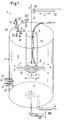
- Fig. 1 shows in a schematic, partially sectioned illustration a first embodiment of a mixing device according to the invention, which is designated overall by the reference numeral 1.
- the inventive Mixing device is designed as a bioreactor or as a fermenter. It should be understood, however, that the invention is not limited to such embodiments, but more generally relates to mixing devices with which media are mixed. In particular, these media may be fluids or solids, preferably powders.
- the mixing device according to the invention is suitable for mixing liquids with one another and / or for mixing at least one liquid with a powder or other solid and / or for mixing gases with liquids and / or solids.
- FIG. 1 illustrated first embodiment shows a configured as a bioreactor mixing device 1, which comprises a container 2 for mixing media.
- This container 2 can be configured as a flexible bag, for example as a plastic or plastic bag, or as a rigid container 2, for example made of stainless steel, glass, chrome steel or plastic.
- flexible embodiments of the container 2 are preferred.
- the container 2 comprises at least one inlet, in the present example, six inlets 31,32,33,34,35,36 for the media to be mixed, and at least one outlet 4.
- at least one inlet in the present example, six inlets 31,32,33,34,35,36 for the media to be mixed, and at least one outlet 4.
- ports 41 in the wall of the container 2 more ports 41 (ports) intended.
- measuring sensors can be introduced in order to determine the temperature, the pH or other variables by measurement.
- the ports 41 can also be used to remove samples from the container 2.
- the container 2 has only one inlet or only one outlet. Also possible are those embodiments which have only one inlet and no outlet or only one outlet and one inlet. In such embodiments, then the only one opening serves both as an inlet and as an outlet.
- a central recess 5 is provided, which extends in a longitudinal direction A into the container 2 and which is delimited by a wall 51 against the interior 6 of the container 2.
- the container 2 is designed substantially cylindrical, the longitudinal direction A is the direction of the cylinder axis.
- the recess 5 extends from the representation according to the upper end face of the cylindrical container 2 in the interior 6 and is delimited by the wall 51 sealingly from the interior 6, so that no medium from the interior 6 of the container 2 can penetrate into the recess 5.
- the recess 5 is provided with a flexibly configured wall 51, in particular such that the extent of the recess 5 in the longitudinal direction A is variable.
- the wall 51 is designed as a bellows, which is collapsible andorganizziehbar in the longitudinal direction A - comparable to a concertina.
- the flexible configuration of the wall 51 can also be realized by using a flexible rubber hose or a flexible plastic hose.
- a permanent-magnetic mixing element 7 is provided adjacent to the recess 5, with which the media can be mixed. Further, in the recess 5, a drive unit 8 is provided, with which the mixing element 7 can be set in rotation via a magnetic coupling, as the arrow C in Fig. 1 suggests.
- the drive unit 8 is movably arranged in the recess 5, so that the position of the mixing element 7 in the container 2 can be changed in a controlled manner.
- the drive unit 8 is arranged hanging on a cord 9 or a rope or a train in the recess 5 in this embodiment.
- the cord 9 extends over a guide roller 91 to a in Fig. 1 not shown winding device, such as a winch, with the cord 9 motor or by hand can be wound up and unwound.
- the drive unit 8 in the recess 5 is controlled to move - up and down along the longitudinal direction A as shown.
- the mixing element 7 follows by the magnetic coupling of the drive unit 8 and can be controlled in this way along the longitudinal direction A on and be moved off.
- a preferred measure is that the inner end of the recess 5 - thus according to the illustration in Fig. 1 the lower end of the recess 5 - a cup-like reinforcement 52 for receiving the drive unit 8 has. The drive unit 8 then rests on the bottom of the cup-like reinforcement 52.
- the recess 5 or the wall 51 is designed so that it can be extended or pushed together substantially over the entire extent of the container 2 in the longitudinal direction A.
- the elastic properties of the wall 51 are preferably chosen such that the recess 5 can be stretched by the weight of the drive unit 8 up to the lower end, ie the bottom of the container 2.
- the wall 51 contracts due to its elastic properties, so that the recess 5 is shortened with respect to the longitudinal direction A.
- the drive unit 8 remains in the cup-like reinforcement 52.
- the drive unit 8 can now be moved up and down in the recess 5 by actuating the winding device as the double arrow B in Fig. 1 suggests. Due to the magnetic coupling, the mixing element 7 follows the movement of the drive unit 8 in the longitudinal direction A and can be brought in this way in the container 2 in any position with respect to the longitudinal direction A and be held there. Thus, the mixing element with respect to the longitudinal direction A between the illustrated lower and upper end of the container 2 in Fig. 1 movable.
- the drive unit 8 sets the mixing element 7 in the operating state via the magnetic coupling in rotation, as the arrow C in Fig. 1 indicates, so as to ensure a good mixing of the media.
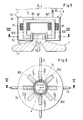
- FIG. 2 shows the drive unit 8 and the mixing element 7 shown in section, wherein the section along the section line II-II in Fig. 3 took place.
- Fig. 3 shows the drive unit 8 and the mixing element 7 in one Fig. 2 vertical sectional view along the section line III-III in Fig. 2 ,
- the drive unit 8 comprises a stator 80, which forms an electrical rotary drive together with the permanent-magnetic mixing element 7.
- the mixing element 7 is thus here the rotor of an electromagnetic rotary drive.
- the mixing element 7 is designed as a permanent magnetic rotor, which forms a bearingless motor together with the stator 80, in which the stator is configured as a bearing and drive stator for the permanent magnetic rotor.
- Such a bearingless engine is z. B. in the EP-A-0 819 330 or the US-A-6,100,618 disclosed.
- bearingless motor is meant that the mixing element 7 is mounted completely magnetic, with no separate magnetic bearings are provided.
- the stator 80 is designed for this purpose as a bearing and drive stator, so it is both stator of the electric drive and stator of the magnetic bearing.
- the stator winding 81 comprises a drive winding of the pole pair number p and a control winding of the pole pair number p ⁇ 1.
- a magnetic rotating field can be generated, which on the one hand exerts a torque on the mixing element 7, which causes its rotation, and which on the other hand exerts an arbitrarily adjustable lateral force on the mixing element, so that its radial position is actively controlled or regulated.
- three degrees of freedom of the mixing element can be actively controlled.
- the mixing element 7 is passively magnetic, that is not controllable, stabilized by reluctance forces.
- the stator 80 comprises, in addition to the stator winding 81, a stator lamination stack 82 which carries the stator winding 81. Further, a plurality of sensors 83 are provided, with which, for example, the position of the mixing element 7 with respect to the stator 80 can be determined or the position of the rotor magnetization or other measured variables, which are necessary for the operation of the bearingless motor or use.
- the stator 80 is disposed in a housing 84, wherein an encapsulated (potted) design is possible to protect the stator 80 from fluids.
- the stator 80 is connected via supply lines 85 to a control and supply unit, not shown, which supplies the stator 80 with energy and comprises the control devices for the drive and the magnetic bearing of the mixing element 7.
- the mixing element 7 comprises a main body 72, which is designed substantially annularly with a plurality of wings 71 extending in the radial direction.
- the main body usually consists of a plastic or chromium steel, which can be sterilized.
- annular permanent magnet 73 which consists of several permanent magnetic segments can be constructed, as well as a likewise annular magnetic yoke 74, preferably an iron yoke, which surrounds the permanent magnet 73 lying radially outward.
- a sensor ring 75 for example made of aluminum, is provided underneath the permanent magnet 74, which may contain sensors and / or interacts with the sensors 83 in the stator 80.
- the annular permanent magnet 73 is configured in this embodiment as a four-pole magnet (polar number 2) and comprises four ring segments, each magnetized in the radial direction homogeneously, wherein adjacent ring segments are each magnetized in the opposite direction, as indicated by the arrows without reference numerals , This results in a four-pole block-shaped or rectangular magnetized rotor or a magnetized mixing element 7.
- the deflection roller 91 on a rod 92 ( Fig. 1 ) attached.
- the rod 92 is provided with a drive, not shown, with which the rod 92 - and thus the guide roller 91 - perpendicular to the longitudinal direction A back and forth is movable.
- the deflection roller 91 is movable to the left and to the right, as indicated by the double arrow with the reference D.
- This movement is transmitted to the drive unit 8 and thus to the magnetically coupled mixing element 7, so that the mixing element 7 can be moved and positioned in two dimensions by the combination of the lateral movement of the deflection roller 91 with the up and down movement. Due to the flexible design the wall 51, this can also follow the two-dimensional movement of the drive unit 8.
- the drive unit 8 and thus the mixing element 7 can be moved in all three dimensions within the container 2.
- the rod 92 is pivotally mounted, for example, such that it is rotatable or pivotable about an axis parallel to the longitudinal direction A.
- the mixing device 1 which is designed here as a bioreactor, works as follows.
- the container 2 for single use this is designed as a flexible bag, preferably as a plastic bag.
- the mixing element 7 is then usually designed as a disposable part for the single operation and already integrated into the container 2.
- an iron part, not shown can be provided, which holds the mixing element 7 in the vicinity of the recess 5, as long as the drive unit 8 is not yet in the recess 5.
- the container 2 is placed and the iron part, not shown, removed from the recess 5.
- the drive unit 8 is inserted into the recess 5.
- the container 2 is filled with the media to be mixed.
- the inlets 31, 32, 33, 34 are provided for the liquids and possibly to be added solids, which are present for example in powder form.
- the liquid is for example a nutrient solution, for example a sugar solution.
- two gas supply lines 35 and 36 are provided, each of which is provided with a filter element 351 and 361, respectively.
- the gas supply 35 serves to apply a gas from above to the liquid contained in the container 2.
- the gas supply 36 serves to inject a gas from below into the liquid in the container 2 (Sparge).
- the magnetically mounted mixing element 7 is rotated (arrow C) and mixed media in the container 2.
- the mixing element 7 by a corresponding movement of the drive unit 8 in be moved up and down along the longitudinal direction A as desired (as shown in FIG Fig. 1 ) and by a corresponding movement of the guide roller 91 according to the representation to the right and to the left.
- the mixing element 7 can be moved and positioned over the entire extent of the container 2 in the longitudinal direction A, ie as shown, from the bottom of the container 2 to its upper end.
- a gas outlet 42 is further provided, through which a gas can escape from the container 2.
- the gas outlet 42 is provided with a filter 421.
- samples 41 can be taken from the interior 6 of the container 2 through the connections 41. Furthermore, can Measuring sensors are introduced into the interior 6 to monitor process parameters such as temperature.
- the container 2 can be emptied through the outlet 4.
- the drive unit 8 comprises a stator 80 which, together with the permanent-magnetic mixing element 7, forms an electrical rotary drive.
- This is preferably designed as a bearingless motor.
- other embodiments of the electric rotary drive are possible, for example embodiments with separate magnetic bearings for the mixing element, or the combination of magnetic bearings with other bearings.
- Fig. 1 . 2.3 illustrated embodiment comprises an electric rotary drive, which is constructed according to the principle of the external rotor, ie the magnetically active part of the mixing element 7 is located outside of the stator 80th
- the mixing element 7 Since the mixing element 7 is arranged outside around the recess 5 around, it can follow the movement of the stator 80 in the longitudinal direction A, even in a rigid configuration of the wall 51.
- FIG. 1 Another variant of the in the Fig. 1 . 2.3 illustrated embodiment is to design the electric rotary drive as an internal rotor.
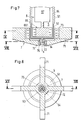
- FIGS. 5 and 6 show such a variant of the first embodiment.
- Fig. 5 shows the drive unit 8 and the mixing element 7 in one Fig. 3 analogue sectional view.
- the section line VV is in Fig. 6 located.
- Fig. 6 shows the drive unit 8 and the mixing element 7 in one Fig. 5 vertical sectional view along the section line VI-VI in Fig. 5 ,
- the electric rotary drive is designed as a bearingless motor, with the bearing and drive stator 80 and serving as a rotor mixing element 7.
- the stator 80 (see in particular Fig. 5 ) is constructed in this variant according to the principle of the temple engine.
- the stator 80 has a plurality of stator teeth 802 connected by a yoke 801, each L-shaped with the longer leg extending in the longitudinal direction and the shorter leg radially later runs inside.
- the stator windings 81 are respectively provided on the longer legs of the stator teeth 802.
- the magnetically active part of the mixing element 7 serving as a rotor is mounted between the shorter limbs of the stator teeth 802.
- the mixing element 7 serving as a rotor comprises the main body 72, which is configured with a plurality of wings 71 extending in the radial direction is.
- a disc-shaped permanent magnet 73 whose magnetization in the FIGS. 5 and 6 is indicated by the arrows without reference numerals.
- the permanent magnet 73 is magnetized two-pole (number of poles 1) sinusoidally, of course, many other forms of magnetization are possible.
- the permanent magnet is as shown in FIG Fig. 5 above the wings 71 provided in a central part of the base body 72 which is mounted in the operating state between the shorter legs of the stator teeth 802. Accordingly, the wings are shown below the stator 80.
- the drive unit 8 comprises an electric rotary drive 87, which is magnetically coupled to the mixing element 7 for driving the mixing element 7.
- the mixing element 7 is no longer the rotor of the electric rotary drive, but the entire electric rotary drive including its rotor is provided in the drive unit 8.
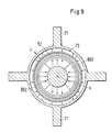
- Fig. 7 shows a section through the drive unit 8 and the mixing element 7 along the section line VII-VII in Fig. 8 ,
- the representation is analogous to the representation in FIG Fig. 2
- Fig. 8 and Fig. 9 each show the drive unit 8 and the mixing element 7 in one Fig. 7 vertical sectional view along the section line VIII-VIII and IX-IX in Fig. 7 ,
- Fig. 7 shows the drive unit 8 and the mixing element 7 in a sectional view along the longitudinal direction A.
- the drive unit 8, the in the recess 5 is arranged comprises an electric rotary drive 87, which drives a rotor 86.
- Both the electric rotary drive 87 and the rotor 86 are arranged in the housing 84, wherein - as in the first embodiment - an encapsulated version is possible.
- the rotor 86 is magnetically coupled to the mixing element 7 to drive its rotation.
- the rotor 86 (see in particular Fig. 9 ) a rotor magnet 861, which is designed here as a ring-shaped permanent magnet, which encloses a rotor core 862.
- the annular rotor magnet 861 is designed in this embodiment as a four-pole magnet (Polpariere 2) and comprises four ring segments, each magnetized in a homogeneous radial direction, wherein adjacent ring segments are each magnetized in the opposite direction, as indicated by the arrows without reference numerals , This results in a four-pole block or rectangular magnetized rotor 861.
- Polypariere 2 a four-pole magnet
- ring segments each magnetized in a homogeneous radial direction, wherein adjacent ring segments are each magnetized in the opposite direction, as indicated by the arrows without reference numerals , This results in a four-pole block or rectangular magnetized rotor 861.
- many other rotor magnetizations are possible.
- the cup-like reinforcement 52 at its lower end according to the representation a centrally disposed pin 54, on which a conical guide member 53 is provided, which cooperates with a likewise conical bearing element 76 in the mixing element 7, so as to the mixing element 7 with respect to Center recess 5 or lead.
- the mixing element 7 with the main body 72 has the radially outwardly extending wings 71.
- the annular permanent magnet 73 is provided, which in this embodiment designed as a four-pole magnet (Polpariere 2) and four ring segments, which are each magnetized homogeneously in the radial direction, wherein adjacent ring segments are each magnetized in the opposite direction, as by the arrows without reference in Fig. 9 is indicated. This results in a four-pole block-shaped or rectangular magnetized mixing element 7.
- the rotor 86 is rotated by the rotary drive 87.
- the mixing element 7 is then set in rotation via the magnetic coupling, wherein it is centered and guided by the interaction of the bearing element 76 with the guide element 53 with respect to the recess 5.
- the rotary drive 87 is moved with the rotor 86 in the recess 5 along the longitudinal direction A, that is, as shown in FIG Fig. 7 is moved up and down, the mixing element 7 follows this movement.
- the wall 51 is pushed together, in a representation according to the downward movement, the wall 51 expands along the longitudinal direction A.
- the statements made for the first embodiment apply analogously to the second embodiment as well.
- the drive unit 8 and thus the mixing element 7 can be moved or positioned transversely to the longitudinal direction A at least in one direction.
- the second embodiment may be formed so that the rotor 86, which drives the rotational movement of the mixing element 7, may be arranged outwardly with respect to the magnetically active part of the mixing element 7 - for example, in a similar manner as in Fig. 5 is shown.
- Fig. 10 is a schematic representation of a third embodiment of an inventive mixing device 1 is shown. This third embodiment can be realized in particular using the first embodiment or using the second embodiment.
- the reference numerals have the meanings already explained.
- a rigid support vessel 100 is provided, which is made of chrome steel, stainless steel or plastic.
- This rigid support vessel 100 receives the container 2, which is particularly preferably designed as a flexible bag, for example as a plastic bag, and in particular as a disposable container for single use.
- the drive device 8, which is not visible in this illustration, as well as the mixing element 7 and the devices for moving the drive device 8, can be configured as in the first and / or second embodiment.
- the rigid support vessel 100 is arranged on a mobile frame 101 and is secured by a railing 102 against slipping or falling.
- a stand 107 is further mounted, at the top end according to the illustration one end of the rod 92 is provided.
- the winding device 105 is mounted, with which the drive unit 8 and thus the mixing element 7 in the direction of the longitudinal direction A is movable up and down.
- the rod 92 can be designed so that with her the winding device 105 and thus the drive unit 8 transversely to the longitudinal direction A back and forth, as the double arrow D in Fig. 10 suggests.
- the already explained rotary or pivotal movement of the rod 92 can be realized.
- the control and supply unit 104 is also provided on the frame 101 and / or on the rigid support vessel 100, which supplies, controls and controls the drive unit via the supply lines 85 and controls the movement of the drive unit 8 relative to the recess 5 , ie in particular the winding device 105 and, if appropriate, the movement of the rod 92.
- further devices may be provided, for example, devices for controlling the temperature of the container 2 and its contents. These further devices can also be supplied and / or controlled by the control and supply unit 104.
- This third embodiment allows optimal use of flexible containers 2, such as plastic bags. After use, the container 2 can be disposed of and replaced with a new disposable container 2. This eliminates, for example, expensive sterilization work.
- the invention further proposes a container 2 for a mixing device which is particularly suitable for a mixing device 1 according to the invention.
- the container 2 is designed as a flexible bag for single use and contains a permanent magnetic mixing element 7, which may be configured as in the Ausf ⁇ 1 ⁇ 4hrung examples described above.
- the container 2 has a central recess 5, in which a drive unit 8 can be arranged to be movable, wherein this movement over a substantial part and preferably over the entire extent of the container 2 in the direction of the recess 5 is possible.
- the recess 5 is bounded by a wall 51, which is flexible and is designed so that the expansion of the recess 5 in its longitudinal direction A is veräbderbar.
- the container 2 can be configured and / or packaged as a flexible bag or as a sterilized flexible bag.
Abstract
Description
Die Erfindung betrifft eine Mischvorrichtung mit einem Behälter zum Mischen von Medien sowie einen Behälter für eine solche Mischvorrichtung gemäss dem Oberbegriff des unabhängigen Patentanspruchs der jeweiligen Kategorie.The invention relates to a mixing device with a container for mixing media and a container for such a mixing device according to the preamble of the independent claim of the respective category.
In der pharmazeutischen und in der biotechnologischen Industrie werden häufig Lösungen und Suspensionen hergestellt, die eine sorgfältige Durchmischung der Komponenten verlangen. Beispiele hierfür sind die Deaktivierung von Viren durch massive Änderung des pH-Wertes oder die Herstellung von Puffern. Auch Prozesse in Bioreaktoren, in denen speziell herangezüchtete Mikroorganismen oder Zellen unter möglichst optimalen Bedingungen in einem Nährmedium kultiviert werden, um entweder die Zellen selbst, z.B. Gewebezellen, oder Teile von ihnen oder ihre Stoffwechselprodukte zu gewinnen, verlangen häufig eine sorgfältige Durchmischung der Zellkulturen mit Gasen.In the pharmaceutical and biotechnological industries, solutions and suspensions are frequently produced which require careful mixing of the components. Examples include the deactivation of viruses by massive change in the pH or the production of buffers. Also, processes in bioreactors in which specially grown microorganisms or cells are cultured under optimal conditions in a nutrient medium to either the cells themselves, e.g. Tissue cells, or parts of them or their metabolites, often require careful mixing of the cell cultures with gases.
Allen diesen Prozessen ist es gemeinsam, dass sie sehr häufig unter sterilen Bedingungen durchgeführt werden müssen, um eine Kontamination beispielsweise des gezüchteten Gewebes zu vermeiden. Üblicherweise hat man daher solche Prozesse in Edelstahl-, Glas- oder Chromtanks durchgeführt, die vorher aufwändig sterilisiert werden. In letzter Zeit zeichnet sich immer mehr der Trend ab, derartige Prozesse in flexiblen Kunststoffbeuteln durchzuführen, die für den Einmalgebrauch gedacht sind. Häufig werden solche Beutel bereits bei der Herstellung sterilisiert und dem Kunden in steriler Verpackung zugestellt. Beispiele für solche Bioreaktoren für den Einmalgebrauch finden sich in der
Für das Durchmischen der Komponenten sind Mischer oder Rührer in den Gefässen vorgesehen. Da die Prozesse häufig unter kontrollierter Atmosphäre durchgeführt werden, also in Gefässen, die gegenüber der Umgebung abgeschlossen sind, stellt die Durchführung der rotierenden Achsen in das Gefäss eine mögliche Quelle für eine Kontamination dar, beispielsweise auch durch Abrieb in den Gleitdichtungen der Welle. Ferner können sich in den Durchführungen Mikroorganismen ansammeln, welche beispielsweise die Sterilität gefährden. Diese Probleme lassen sich vermeiden bzw. lösen, indem man das Rühr- oder Mischelement magnetisch an einen ausserhalb des Gefässes befindlichen Drehantrieb koppelt. Eine derartige Lösung wird beispielsweise in der
Auch bei Verwendung von Rührern oder Mischern ist es häufig sehr schwierig, eine homogene und gradientenfreie Durchmischung der verschiedenen Komponenten zu gewährleisten. Durch die Mischer kommt es zu Strömungen mit unterschiedlichen Turbulenzen, wobei die Turbulenzen in der Regel in der Nähe der Mischer wesentlich stärker sind als in Bereichen, die weit entfernt von den Mischern sind. Dies hat zur Folge, dass sich eine homogene Durchmischung -wenn überhaupt - nur sehr langsam aufbaut. Hier will die Erfindung Abhilfe schaffen.Even when using stirrers or mixers, it is often very difficult to ensure a homogeneous and gradient-free mixing of the various components. The mixers produce flows of varying turbulence, with turbulence typically being much greater near the mixers than in areas far from the mixers. This has the consequence that a homogeneous mixing - if any - builds up only very slowly. The invention aims to remedy this situation.
Es ist daher eine Aufgabe der Erfindung eine Mischvorrichtung sowie einen dafür geeigneten Behälter vorzuschlagen, der eine gute und homogene Durchmischung ermöglicht, insbesondere auch in Bioreaktoren.It is therefore an object of the invention to propose a mixing device and a suitable container, which allows a good and homogeneous mixing, especially in bioreactors.
Die diese Aufgabe lösenden Gegenstände der Erfindung sind durch die Merkmale der unabhängigen Patentansprüche gekennzeichnet.The problem-solving objects of the invention are characterized by the features of the independent claims.
Erfindungsgemäss wird also eine Mischvorrichtung vorgeschlagen mit einem Behälter zum Mischen von Medien, welcher mindestens einen Einlass für die zu mischenden Medien oder mindestens einen Auslass aufweist, wobei eine zentrale Ausnehmung vorgesehen ist, die sich in einer Längsrichtung in den Behälter hinein erstreckt und durch eine Wandung gegen den Innenraum des Behälters abgegrenzt ist, wobei in dem Behälter benachbart zu der Ausnehmung ein permanentmagnetisches Mischelement zum Mischen der Medien vorgesehen ist und wobei in der Ausnehmung eine Antriebseinheit vorgesehen ist, mit welcher das Mischelement über eine magnetische Kopplung in Rotation versetzt werden kann. Die Antriebseinheit ist in der Ausnehmung bewegbar angeordnet, sodass die Position des Mischelements in dem Behälter kontrolliert veränderbar ist.According to the invention, therefore, a mixing device is proposed with a container for mixing media, which has at least one inlet for the media to be mixed or at least one outlet, wherein a central recess is provided which extends in a longitudinal direction into the container and through a wall against the interior of the Container is delimited, wherein in the container adjacent to the recess, a permanent magnetic mixing element for mixing the media is provided and wherein in the recess, a drive unit is provided, with which the mixing element can be rotated by a magnetic coupling in rotation. The drive unit is arranged movably in the recess so that the position of the mixing element in the container can be changed in a controlled manner.
Bei dieser Mischvorrichtung kann das in dem Behälter befindliche Mischelement in einem weiten Bereich frei verschoben werden, wodurch eine deutlich bessere und räumlich homogenere Durchmischung erzielt wird. Da zudem die Positionierung des Mischelements ebenso wie sein Antrieb über eine magnetische Kopplung erfolgt, bedarf es keiner aufwändiger Einrichtungen im oder Durchführungen in den Behälter, sodass zum einen die Vorrichtung einfach vom Aufbau her ist und zum anderen die Gefahr unerwünschter Verunreinigungen im Behälter deutlich reduziert wird.In this mixing device, the mixing element in the container can be moved freely in a wide range, whereby a much better and more spatially homogeneous mixing is achieved. In addition, since the positioning of the mixing element as well as its drive via a magnetic coupling, it requires no elaborate facilities in or implementations in the container, so on the one hand, the device is simple in construction and on the other hand the risk of unwanted contamination in the container is significantly reduced ,
Vorzugsweise ist die Wandung der Ausnehmung flexibel ausgestaltet und insbesondere derart, dass die Ausdehnung der Ausnehmung in der Längsrichtung veränderbar ist. Dies kann beispielsweise realisiert werden, indem die Ausnehmung in Form oder nach dem Prinzip eines Balgs oder als flexibler Schlauch ausgestaltet ist. Dadurch wird eine Vielzahl zusätzlicher Ausgestaltungen und Varianten der Mischvorrichtung ermöglicht. Beispielsweise kann das Mischelement dann auch nach dem Prinzip eines Innenläufers magnetisch in der Antriebseinheit gelagert sein und von dieser angetrieben werden.Preferably, the wall of the recess is designed to be flexible and in particular such that the extent of the recess in the longitudinal direction is variable. This can for example be realized by the recess is designed in the form or according to the principle of a bellows or as a flexible hose. This allows a variety of additional configurations and variants of the mixing device. For example, the mixing element can then be magnetically supported in the drive unit and driven by it, even according to the principle of an internal rotor.
Eine bevorzugte Ausgestaltung besteht darin, dass die Antriebseinheit ein elektrischer Drehantrieb ist, der zum Antreiben des Mischelements magnetisch mit dem Mischelement gekoppelt ist. Das heisst, die Drehbewegung des Rotors eines elektrischen Drehantriebs wird über eine magnetische Kopplung zum Antreiben der Rotationsbewegung des Mischelements eingesetzt.A preferred embodiment is that the drive unit is an electric rotary drive which is magnetically coupled to the mixing element for driving the mixing element. That is, the rotational movement of the rotor of an electric rotary drive is used via a magnetic coupling for driving the rotational movement of the mixing element.
Eine andere bevorzugte Ausgestaltung besteht darin, dass die Antriebseinheit einen Stator umfasst, welcher zusammen mit dem Mischelement als Rotor einen elektrischen Drehantrieb bildet. Bei dieser Ausgestaltung ist also das Mischelement selbst Teil des elektrischen Drehantriebs, nämlich dessen Rotor. Besonders bevorzugt ist dabei das Mischelement als permanentmagnetischer Rotor ausgestaltet, der zusammen mit dem Stator einen lagerlosen Motor bildet, bei welchem der Stator als Lager- und Antriebsstator für den permanentmagnetischen Rotor ausgestaltet ist. Diese Ausgestaltung als lagerloser Motor ist äusserst kompakt und platzsparend, weil keine separaten Magnetlager für den Rotor benötigt werden, sondern der Stator sowohl das Antriebsmoment für den Rotor generiert als auch die magnetische Lagerung des Rotor realisiert.Another preferred embodiment is that the drive unit comprises a stator, which together with the Mixing element forms a rotary electric drive as a rotor. In this embodiment, therefore, the mixing element itself is part of the electric rotary drive, namely its rotor. Particularly preferably, the mixing element is designed as a permanent magnetic rotor, which forms a bearingless motor together with the stator, in which the stator is configured as a bearing and drive stator for the permanent magnetic rotor. This embodiment as a bearingless motor is extremely compact and space-saving, because no separate magnetic bearings are needed for the rotor, but the stator generates both the drive torque for the rotor and realized the magnetic bearing of the rotor.
Eine apparativ besonders einfach Ausgestaltung ist es, wenn die Antriebseinheit in der Ausnehmung hängend angeordnet ist. Dann kann die Antriebseinheit in einfacherweise über einen Seilzug oder eine Kette in der Ausnehmung auf und ab bewegt werden, um so die Position des Mischelements im Behälter kontroliert zu verändern.An apparatus of particularly simple design is when the drive unit is arranged hanging in the recess. Then, the drive unit can be easily moved up and down in the recess via a cable or a chain in order to change the position of the mixing element in the container in a controlled manner.
Eine vorteilhafte Massnahme besteht darin, dass das innenliegende Ende der Ausnehmung eine becherartige Verstärkung, insbesondere aus Kunststoff aufweist. Diese Verstärkung dient als Auflagefläche für das Mischelement, wenn die Antriebseinheit deaktiviert ist. Die Verstärkung verhindert eine Verletzung der Wandung der Ausnehmung.An advantageous measure consists in that the inner end of the recess has a cup-like reinforcement, in particular made of plastic. This reinforcement serves as a bearing surface for the mixing element when the drive unit is deactivated. The reinforcement prevents injury to the wall of the recess.
Eine vorteilhafte Variante besteht darin, dass die Antriebseinheit quer zur Längsrichtung der zentralen Ausnehmung bewegbar ist. Durch diese Massnahme lässt sich das Mischelement nicht nur in der Längsrichtung der Ausnehmung verschieben sondern auch in einer dazu senkrechten Ebene. Dies ist insbesondere bei grösseren Behältern vorteilhaft, um eine noch homogenere oder schnellere Durchmischung zu erreichen.An advantageous variant is that the drive unit is movable transversely to the longitudinal direction of the central recess. By this measure, the mixing element can be moved not only in the longitudinal direction of the recess but also in a plane perpendicular thereto. This is particularly advantageous for larger containers to achieve even more homogeneous or faster mixing.
Besonders bevorzugt ist der Behälter als flexibler Beutel oder als sterilisierter flexibler Beutel ausgestaltet. Damit wird dem heute insbesondere für Bioreaktoren zu beobachtenden Trend Rechnung getragen, einfach und kostengünstig zu produzierende Behälter zu verwenden. Der Behälter ist vorzugsweise als Wegwerf-Behälter für den Einmalgebrauch ausgestaltet.Particularly preferably, the container is configured as a flexible bag or as a sterilized flexible bag. This takes into account the current trend, especially for bioreactors, of using containers that are easy and inexpensive to produce. The container is preferably designed as a disposable container for single use.
Dadurch entfallen aufwändige Reinigungs- und/oder Sterilisierungsvorgänge, wie sie üblicherweise in Edelstahl oder Glasbehältern anfallen.This eliminates the need for expensive cleaning and / or sterilization processes, such as those usually incurred in stainless steel or glass containers.
Gemäss einer bevorzugten Ausgestaltung hat die Mischvorrichtung ein starres Stützgefäss, welches den Behälter aufnimmt, der vorzugsweise als flexibler Beutel ausgestaltet ist. Diese Ausgestaltung ermöglicht es, den Behälter, der mit den Medien in Kontakt kommt, für den Einmalgebrauch auszulegen, während die anderen Komponenten mehrfach genutzt werden können.According to a preferred embodiment, the mixing device has a rigid support vessel which receives the container, which is preferably designed as a flexible bag. This configuration makes it possible to design the container that comes into contact with the media for single use, while the other components can be used multiple times.
Besonders bevorzugt ist die Mischvorrichtung als Bioreaktor oder als Fermenter ausgestaltet, weil hier die Vorteile der magnetischen Positionierbarkeit und der magnetischen Lagerung des Mischelements besonders gut genutzt werden können.Particularly preferably, the mixing device is designed as a bioreactor or as a fermenter, because here the advantages of the magnetic positioning and the magnetic bearing of the mixing element can be used particularly well.
Ferner wird durch die Erfindung ein Behälter vorgeschlagen, für eine Mischvorrichtung, die erfindungsgemäss ausgestaltet ist, wobei der Behälter als flexibler Beutel für den Einmalgebrauch ausgestaltet ist, ein permanentmagnetisches Mischelement enthält und eine zentrale Ausnehmung aufweist, in welcher eine Antriebseinheit bewegbar angeordnet werden kann.Further, the invention proposes a container for a mixing device, which is designed according to the invention, wherein the container is designed as a flexible bag for single use, contains a permanent magnetic mixing element and has a central recess in which a drive unit can be arranged to be movable.
Die Ausgestaltung des Beutels mit der zentralen Ausnehmung ermöglicht es, die Position des Mischelements in dem Behälter kontrolliert zu verändern.The configuration of the bag with the central recess makes it possible to control the position of the mixing element in the container controlled.
Wie bereits vorne erläutert, wird die Ausnehmung vorzugsweise durch eine Wandung begrenzt, die flexibel ist und so ausgestaltet ist, dass die Ausdehnung der Ausnehmung in einer Längsrichtung veränderbar ist.As already explained above, the recess is preferably bounded by a wall, which is flexible and is configured such that the extent of the recess in a longitudinal direction is variable.
Weiter vorteilhafte Massnahmen und Ausgestaltungen der Erfindung ergeben sich aus den abhängigen Ansprüchen.Further advantageous measures and embodiments of the invention will become apparent from the dependent claims.
Im Folgenden wird die Erfindung anhand von Ausführungsbeispielen und anhand der Zeichnung näher erläutert. In der schematischen Zeichnung zeigen teilweise im Schnitt:
- Fig. 1:
- eine schematische Darstellung eines ersten Ausführungsbeispiels einer erfindungsgemässen Mischvorrichtung,
- Fig.2:
- eine Schnittdarstellung der Antriebseinheit und des Mischelements entlang der Schnittlinie II-II in
Fig. 3 , - Fig. 3:
- eine Schnittdarstellung entlang der Schnittlinie III-III in
Fig. 2 , - Fig. 4:
- ein Variante des ersten Ausführungsbeispiels in einer Schnittdarstellung
- Fig. 5:
- eine Variante für die Antriebseinheit und das Mischelement in einer Schnittdarstellung entlang der Schnittlinie V-V in
Fig. 6 , - Fig. 6:
- eine Schnittdarstellung entlang der Schnittlinie VI-VI in
Fig. 5 , - Fig. 7:
- eine Schnittdarstellung der Antriebseinheit und des Mischelements eines zweiten Ausführungsbeispiels der erfindungsgemässen Mischvorrichtung entlang der Schnittlinie VII-VII in
Fig. 8 , - Fig. 8:
- eine Schnittdarstellung entlang der Schnittlinie VIII-VIII in
Fig. 7 , - Fig. 9:
- eine Schnittdarstellung entlang der Schnittlinie IX-IX in
Fig. 7 , und - Fig. 10:
- eine schematische Darstellung eines dritten Ausführungsbeispiels einer erfindungsgemässen Mischvorrichtung.
- Fig. 1:
- a schematic representation of a first embodiment of a mixing device according to the invention,
- Figure 2:
- a sectional view of the drive unit and the mixing element along the section line II-II in
Fig. 3 . - 3:
- a sectional view along the section line III-III in
Fig. 2 . - 4:
- a variant of the first embodiment in a sectional view
- Fig. 5:
- a variant of the drive unit and the mixing element in a sectional view along the section line VV in
Fig. 6 . - Fig. 6:
- a sectional view along the section line VI-VI in
Fig. 5 . - Fig. 7:
- a sectional view of the drive unit and the mixing element of a second embodiment of the inventive mixing device along the section line VII-VII in
Fig. 8 . - Fig. 8:
- a sectional view taken along section line VIII-VIII in
Fig. 7 . - Fig. 9:
- a sectional view taken along the section line IX-IX in
Fig. 7 , and - Fig. 10:
- a schematic representation of a third embodiment of an inventive mixing device.
Das in
Der Behälter 2 umfasst mindestens einen Einlass, im vorliegenden Beispiel sechs Einlässe 31,32,33,34,35,36 für die zu mischenden Medien, sowie mindestens einen Auslass 4. Zudem sind in der Wandung des Behälters 2 mehrere Anschlüsse 41 (Ports) vorgesehen. Durch diese können beispielsweise Messsensoren eingeführt werden, um die Temperatur, den pH-Wert oder auch andere Grössen messtechnisch zu bestimmen. Die Anschlüsse 41 können ferner dazu genutzt werden, Proben aus dem Behälter 2 zu entnehmen.The
Es ist auch möglich, dass der Behälter 2 nur einen Einlass oder nur einen Auslass aufweist. Auch sind solche Ausgestaltungen möglich, die nur einen Einlass und keinen Auslass oder nur einen Auslass und keinen Einlass aufweisen. Bei derartigen Ausgestaltungen dient dann die nur eine Öffnung sowohl als Einlass als auch als Auslass.It is also possible that the
Es ist eine zentrale Ausnehmung 5 vorgesehen, welche sich in einer Längsrichtung A in den Behälter 2 hinein erstreckt und welche durch eine Wandung 51 gegen den Innenraum 6 des Behälters 2 abgegrenzt ist. Im vorliegenden Beispiel ist der Behälter 2 im wesentlichen zylindrisch ausgestaltet, die Längsrichtung A ist die Richtung der Zylinderachse. Die Ausnehmung 5 erstreckt sich von der darstellungsgemäss oberen Stirnfläche des zylindrischen Behälters 2 in dessen Innenraum 6 und ist durch die Wandung 51 dichtend von dem Innenraum 6 abgegrenzt, sodass kein Medium aus dem Innenraum 6 des Behälters 2 in die Ausnehmung 5 eindringen kann.A
Besonders bevorzugt ist die Ausnehmung 5 mit einer flexibel ausgestalteten Wandung 51 versehen, insbesondere derart, dass die Ausdehnung der Ausnehmung 5 in der Längsrichtung A veränderbar ist. Im vorliegenden Ausführungsbeispiel ist die Wandung 51 als Balg ausgestaltet, der in Längsrichtung A zusammenschiebbar und auseinanderziehbar ist - vergleichbar mit einer Ziehharmonika.Particularly preferably, the
Alternativ kann die flexible Ausgestaltung der Wandung 51 auch realisiert werden, indem ein Schlauch aus flexiblem Gummi oder ein Schlauch aus einem flexiblen Kunststoff verwendet werden.Alternatively, the flexible configuration of the
Im Innenraum 6 des Behälters 2 ist benachbart zu der Ausnehmung 5 ein permanentmagnetisches Mischelement 7 vorgesehen, mit welchem die Medien durchmischt werden können. Ferner ist in der Ausnehmung 5 eine Antriebseinheit 8 vorgesehen, mit welcher das Mischelement 7 über eine magnetische Kopplung in Rotation versetzt werden kann, wie dies der Pfeil C in
Erfindungsgemäss ist die Antriebseinheit 8 in der Ausnehmung 5 bewegbar angeordnet, sodass die Position des Mischelements 7 in dem Behälter 2 kontrolliert veränderbar ist.According to the invention, the
Dazu ist bei diesem Ausführungsbeispiel die Antriebseinheit 8 an einer Schnur 9 oder einem Seil oder einem Zug in der Ausnehmung 5 hängend angeordnet. Die Schnur 9 verläuft über eine Umlenkrolle 91 zu einer in
Eine bevorzugte Massnahme besteht darin, dass das innenliegende Ende der Ausnehmung 5 - also gemäss der Darstellung in
Die Ausnehmung 5 bzw. die Wandung 51 ist so ausgestaltet, dass sie sich im Wesentlichen über die gesamte Erstreckung des Behälters 2 in Längsrichtung A ausdehnen bzw. zusammenschieben lässt. Dazu werden vorzugsweise die elastischen Eigenschaften der Wandung 51 so gewählt, dass die Ausnehmung 5 durch die Gewichtskraft der Antriebseinheit 8 bis zum darstellungsgemäss unteren Ende, also dem Boden des Behälters 2 dehnbar ist. Bei einer Aufwärtsbewegung der Antriebseinheit 8 zieht sich die Wandung 51 durch ihre elastischen Eigenschaften zusammen, sodass sich die Ausnehmung 5 bezüglich der Längsrichtung A verkürzt. Vorzugsweise verbleibt dabei die Antriebseinheit 8 in der becherartigen Verstärkung 52.The
Während des Betriebs der Mischvorrichtung 1 kann nun die Antriebseinheit 8 durch Betätigung der Wickelvorrichtung in der Ausnehmung 5 auf- und abbewegt werden wie dies der Doppelpfeil B in
Je nach Anwendungsfall ist es im Hinblick auf eiune besonders gute Durchmischung besonders vorteilhaft, wenn das Mischelement 7 zyklisch in dem Behälter 2 auf und ab bewegt wird.Depending on the application, it is particularly advantageous in view of egg particularly good mixing when the mixing
Die Antriebseinheit 8 versetzt das Mischelement 7 im Betriebszustand über die magnetische Kopplung in Rotation, wie dies der Pfeil C in
Im Folgenden wird der Antrieb und die Lagerung des Mischelements 7 des ersten Ausführungsbeispiels näher erläutert. Dazu ist in
Bei dem ersten Ausführungsbeispiel umfasst die Antriebseinheit 8 einen Stator 80, der zusammen mit dem permanentmagnetischen Mischelement 7 einen elektrischen Drehantrieb bildet. Das Mischelement 7 ist hier also der Rotor eines elektromagnetischen Drehantriebs. Besonders bevorzugt ist das Mischelement 7 als permanentmagnetischer Rotor ausgestaltet, der zusammen mit dem Stator 80 einen lagerlosen Motor bildet, bei welchem der Stator als Lager- und Antriebsstator für den permanentmagnetischen Rotor ausgestaltet ist.In the first embodiment, the
Ein solcher lagerloser Motor wird z. B. in der
Der Stator 80 umfasst neben der Statorwicklung 81 ein Statorblechpaket 82 welches die Statorwicklung 81 trägt. Ferner sind mehrere Sensoren 83 vorgesehen, mit welchen beispielsweise die Position des Mischelements 7 bezüglich des Stators 80 bestimmbar ist oder die Lage der Rotormagnetisierung oder andere Messgrössen, die für den Betrieb des lagerlosen Motors notwendig sind bzw. Verwendung finden.The
Der Stator 80 ist in einem Gehäuse 84 angeordnet, wobei eine eingekapselte (gepottete) Ausführung möglich ist, um den Stator 80 vor Fluiden zu schützen. Der Stator 80 ist über Versorgungsleitungen 85 mit einer nicht dargestellten Steuer- und Versorgungseinheit verbunden, welche den Stator 80 mit Energie versorgt und die Regeleinrichtungen für den Antrieb und die magnetische Lagerung des Mischelements 7 umfasst.The
Bezüglich der in
Das Mischelement 7 umfasst einen Grundkörper 72, der im wesentlichen ringförmig mit mehreren, sich in radialer Richtung erstreckenden Flügeln 71 ausgestaltet ist. Der Grundkörper besteht üblicherweise aus einem Kunststoff oder aus Chromstahl, der sterilisierbar ist. In den Grundkörper eingelagert ist ein ringförmiger Permanentmagnet 73, welcher aus mehreren permanentmagnetischen Segmenten aufgebaut sein kann, sowie ein ebenfalls ringförmiger magnetischer Rückschluss 74, vorzugsweise ein Eisenrückschluss, welcher den Permanentmagneten 73 radial aussen liegend umschliesst. Ferner ist darstellungsgemäss unterhalb des Permanentmagneten 74 ein Sensorring 75, beispielsweise aus Aluminium, vorgesehen, welcher Sensoren enthalten kann und/oder mit den Sensoren 83 im Stator 80 zusammenwirkt. Der ringförmige Permanentmagnet 73 ist bei diesem Ausführungsbeispiel als vierpoliger Magnet ausgestaltet (Polparzahl 2) und umfasst vier Ringsegmente, die jeweils homogen in radialer Richtung magnetisiert sind, wobei benachbarte Ringsegmente jeweils in die entgegengesetzte Richtung magnetiesiert sind, wie dies durch die Pfeile ohne Bezugszeichen angedeutet ist. Hieraus resultiert ein vierpoliger blockförmig oder rechteckförmig magnetisierter Rotor bzw. ein derartig magnetisiertes Mischelement 7.The mixing
Natürlich sind auch viele andere Arten der Magnetisierung des Mischelements 7 möglich.Of course, many other types of magnetization of the mixing
Bei dem in den
Dazu ist die Umlenkrolle 91 an einer Stange 92 (
Es versteht sich, dass natürlich auch solche Ausgestaltungen möglich sind, bei denen die Antriebseinheit 8 und damit das Mischelement 7 in allen drei Dimensionen innerhalb des Behälters 2 bewegt werden können. Eine weitere Möglichkeit besteht darin, alternativ oder ergänzend die Stange 92 schwenkbar zu lagern beispielsweise derart, dass sie um eine zur Längsrichtung A parallele Achse drehbar bzw. schwenkbar ist.It is understood that, of course, such embodiments are possible in which the
Im Betrieb funktioniert die Mischvorrichtung 1, die hier als Bioreaktor ausgestaltet ist, wie folgt.In operation, the mixing device 1, which is designed here as a bioreactor, works as follows.
Insbesondere bei der Ausgestaltung des Behälters 2 für den Einmalgebrauch ist dieser als flexibler Beutel, vorzugsweise als Plastikbeutel ausgestaltet. Auch das Mischelement 7 ist dann üblicherweise als Wegwerf-Teil für den Einmalbetrieb konzipiert und bereits in den Behälter 2 integriert. In der Ausnehmung 5 kann dann ein nicht dargestelltes Eisenteil vorgesehen sein, welches das Mischelement 7 in der Nachbarschaft der Ausnehmung 5 hält, solange sich die Antriebseinheit 8 noch nicht in der Ausnehmung 5 befindet. Der Behälter 2 wird aufgestellt und das nicht dargestellte Eisenteil aus der Ausnehmung 5 entfernt. Die Antriebseinheit 8 wird in die Ausnehmung 5 eingeführt. Der Behälter 2 wird mit den zu mischenden Medien befüllt. Für die Flüssigkeiten und eventuell beizufügende Feststoffe, die beispielsweise in Pulverform vorliegen, sind die Einlässe 31, 32, 33, 34 vorgesehen. Die Flüssigkeit ist beispielsweise eine Nährlösung, z.B. eine Zuckerlösung. Für die Zuführung der gasförmigen Komponenten sind zwei Gaszuführungen 35 und 36 vorgesehen, von denen jede mit einem Filterelement 351 bzw. 361 versehen ist. Die Gaszuführung 35 dient dazu, ein Gas von oben auf die im Behälter 2 befindliche Flüssigkeit aufzubringen. Die Gaszuführung 36 dient dazu, ein Gas von unten in die Flüssigkeit im Behälter 2 einzublasen (Sparge).In particular, in the embodiment of the
Nachdem der Behälter 2 mit den zu mischenden Medien befüllt ist, wird mittels der Antriebseinheit 8 das magnetisch gelagerte Mischelement 7 in Rotation versetzt (Pfeil C) und durchmischt die Medien im Behälter 2. Dabei kann das Mischelement 7 durch eine entsprechende Bewegung der Antriebseinheit 8 in beliebiger Weise entlang der Längsrichtung A auf- und ab bewegt werden (gemäss der Darstellung in
Für viele Anwendungen ist es ausreichend, das Mischelement 7 auf- und ab zu bewegen. Bei lateral sehr gross ausgedehnten Behältern 2 kann es vorteilhaft sein, das Mischelement zusätzlich quer zur Längsrichtung A in mindestens einer Richtung hin- und her zu bewegen. Diese Hin- und Herbewegung kann gemäss der Darstellung in
Besonders vorteilhaft ist es, wenn das Mischelement 7 über die gesamte Erstreckung des Behälters 2 in Längsrichtung A bewegbar und positionierbar ist, also darstellungsgemäss vom Boden des Behälters 2 bis zu seinem oberen Ende.It is particularly advantageous if the mixing
An dem Behälter 2 ist ferner ein Gasauslass 42 vorgesehen, durch welchen ein Gas aus dem Behälter 2 entweichen kann. Der Gasauslass 42 ist mit einem Filter 421 versehen.On the
Während des Betriebs können durch die Anschlüsse 41 Proben aus dem Innenraum 6 des Behälters 2 entnommen werden. Ferner können Messsensoren in den Innenraum 6 eingeführt werden, um Prozessparameter wie beispielsweise die Temperatur, zu überwachen.During operation,
Der Behälter 2 kann über den Auslass 4 geleert werden.The
Bei diesem ersten Ausführungsbeispiel umfasst die Antriebseinheit 8 einen Stator 80, der zusammen mit dem permanentmagnetischen Mischelement 7 einen elektrischen Drehantrieb bildet. Dieser ist vorzugsweise als lagerloser Motor ausgestaltet. Natürlich sind aber auch andere Ausgestaltungen des elektrischen Drehantriebs möglich, beispielsweise Ausgestaltungen mit separaten Magnetlagern für das Mischelement, oder die Kombination von magnetischen Lagern mit anderen Lagern.In this first exemplary embodiment, the
Das in den
Insbesondere bei solchen Ausführungsbeispielen, die nach dem Prinzip des Aussenläufers aufgebaut sind, ist es auch möglich, die Wandung 51 der Ausnehmung 5 bzw. die Ausnehmung 5 nicht flexibel auszugestalten, sondern beispielsweise als starres Rohr, innerhalb dessen die Antriebseinheit 8 und insbesondere der Stator 80 entlang der Längsrichtung A bewegbar ist, also in einer der
- A. Die bisher gemachten Erläuterungen gelten für die Variante in
Fig. 4 in sinngemäss gleicher Weise. Auf die Darstellung der Sensorik und der Versorgunbgsleitungen ist inFig. 4 verzichtet worden.
- A. The explanations given so far apply to the variant in
Fig. 4 in the same way. The representation of the sensors and the power supply lines is inFig. 4 has been dispensed with.
Da das Mischelement 7 aussen um die Ausnehmung 5 herum angeordnet ist, kann es auch bei einer starren Ausgestaltung der Wandung 51 der Bewegung des Stators 80 in der Längsrichtung A folgen.Since the mixing
Eine andere Variante des in den
Die
Im Folgenden wird nur auf die Unterschiede zu der Ausgestaltung gemäss den
Auch bei dieser Variante ist der elektrische Drehantrieb als lagerloser Motor ausgestaltet, mit dem Lager- und Antriebsstator 80 und dem als Rotor dienenden Mischelement 7. Der Stator 80 (siehe insbesondere
Das als Rotor dienende Mischelement 7 umfasst den Grundkörper 72, der mit mehreren, sich in radialer Richtung erstreckenden Flügeln 71 ausgestaltet ist. In den Grundkörper eingelagert ist ein scheibenförmiger Permanentmagnet 73, dessen Magnetisierung in den
In den
Bei dem zweiten Ausführungsbeispiel umfasst die Antriebseinheit 8 einen elektrischen Drehantrieb 87, der zum Antreiben des Mischelements 7 magnetisch mit dem Mischelement 7 gekoppelt ist. Hier ist also im Unterschied zum ersten Ausführungsbeispiel das Mischelement 7 nicht mehr der Rotor des elektrischen Drehantriebs, sondern der gesamte elektrische Drehantrieb inklusive seinem Rotor ist in der Antriebseinheit 8 vorgesehen.In the second embodiment, the
Der ringförmige Rotormagnet 861 ist bei diesem Ausführungsbeispiel als vierpoliger Magnet ausgestaltet (Polparzahl 2) und umfasst vier Ringsegmente, die jeweils homogen in radialer Richtung magnetisiert sind, wobei benachbarte Ringsegmente jeweils in die entgegengesetzte Richtung magnetiesiert sind, wie dies durch die Pfeile ohne Bezugszeichen angedeutet ist. Hieraus resultiert ein vierpoliger blockförmig oder rechteckförmig magnetisierter Rotor 861. Selbstverständlich sind noch viele andere Rotormagnetisierungen möglich.The
Wie dies insbesondere in
Das Mischelement 7 mit dem Grundkörper 72 weist die sich radial nach aussen erstreckenden Flügel 71 aus. In dem Grundkörper 72 ist der ringförmige Permanentmagnet 73 vorgesehen, der bei diesem Ausführungsbeispiel als vierpoliger Magnet ausgestaltet (Polparzahl 2) und vier Ringsegmente umfasst, die jeweils homogen in radialer Richtung magnetisiert sind, wobei benachbarte Ringsegmente jeweils in die entgegengesetzte Richtung magnetiesiert sind, wie dies durch die Pfeile ohne Bezugszeichen in
Im Betriebszustand wird der Rotor 86 durch den Drehantrieb 87 in Rotation versetzt. Über die magnetische Kopplung wird dann auch das Mischelement 7 in Drehung versetzt, wobei es durch das Zusammenspiel des Lagerelements 76 mit dem Führungselement 53 bezüglich der Ausnehmung 5 zentriert und geführt wird. Wenn nun der Drehantrieb 87 mit dem Rotor 86 in der Ausnehmung 5 entlang der Längsrichtung A bewegt wird, also gemäss der Darstellung in
Bezüglich der Bewegung der Antriebseinheit 8 und des Mischelements 7 gelten die Ausführungen, die für das erste Ausführungsbeispiel gemacht wurden, in sinngemäss gleicher Weise auch für das zweite Ausführungsbeispiel. Insbesondere ist es auch bei dem zweiten Ausführungsbeispiel eine mögliche Variante, dass die Antriebseinheit 8 und damit das Mischelement 7 mindestens in einer Richtung quer zur Längsrichtung A bewegbar bzw. positionierbar ist. Es versteht sich, dass auch das zweite Ausführungsbeispiel so ausgebildet sein kann, dass der Rotor 86, welcher die Drehbewegung des Mischelements 7 antreibt, aussenliegend bezüglich des magnetisch wirksamen Teils des Mischelements 7 angeordnet sein kann - beispielsweise in sinngemäss gleicher Weise, wie dies in
Natürlich sind für die Lagerung des Mischelements 7 bezüglich der Ausnehmumg 5 bzw. der Antriebseinheit 8 auch andere Varianten möglich, beispielsweise separate Magnetlager.Of course, other variants are possible for the storage of the mixing
In
Bei dieser Mischvorrichtung 1, die insbesondere ein Bioreaktor oder ein Fermenter sein kann, ist ein starres Stützgefäss 100 vorgesehen, welches aus Chromstahl, Edelstahl oder Kunststoff gefertigt ist. Dieses starre Stützgefäss 100 nimmt den Behälter 2 auf, der besonders bevorzugt als flexibler Beutel beispielsweise als Plastiksack ausgestaltet ist und inbesondere als Wegwerf-Behälter für den Einmalgebrauch. Die in dieser Darstellung nicht sichtbare Antriebsvorichtung 8 sowie das Mischelement 7 und die Einrichtungen zur Bewegung der Antriebsvorrichtung 8 können wie im ersten und/oder zweiten Ausführungsbeispiel ausgestaltet sein. Das starre Stützgefäss 100 ist auf einem fahrbaren Gestell 101 angeordnet und wird durch ein Geländer 102 gegen Verrutschen bzw. Stürzen gesichert.In this mixing device 1, which may be in particular a bioreactor or a fermenter, a
Auf dem Gestell 101 ist ferner ein Ständer 107 montiert, an dessen darstellungsgemäss oberen Ende das eine Ende der Stange 92 vorgesehen ist. Am anderen Ende der Stange 92 ist die Wickelvorrichtung 105 montiert, mit welcher die Antriebseinheit 8 und damit das Mischelement 7 in Richtung der Längsrichtung A auf und ab bewegbar ist. Wie bereits weiter vorne erläutert, kann die Stange 92 so ausgestaltet sein, dass mit ihr die Wickelvorrichtung 105 und damit die Antriebseinheit 8 quer zur Längsrichtung A hin und her bewegbar ist, wie dies der Doppelpfeil D in
An dem Gestell 101 und/oder an dem starren Stützgefäss 100 ist ferner die Steuer- und Versorgungseinheit 104 vorgesehen, welche zum einen über die Versorgungsleitungen 85 die Antriebseinheit versorgt, steuert und kontrolliert und zum anderen die Bewegung der Antriebseinheit 8 relativ zu der Ausnehmung 5 steuert, also insbesondere die Wickelvorrichtung 105 und gegebenenfalls die Bewegung der Stange 92.The control and
In dem Stützgefäss können weitere Einrichtungen vorgesehen sein, beispielsweise Einrichtungen zum Temperieren des Behälters 2 bzw. seines Inhalts. Auch diese weiteren Einrichtungen können von der Steuer- und Versorgungseinheit 104 versorgt und/oder angesteuert werden.In the support vessel further devices may be provided, for example, devices for controlling the temperature of the
Dieses dritte Ausführungsbeispiel ermöglicht eine optimale Nutzung von flexiblen Behältern 2, wie beispielsweise Plastiksäcken. Nach dem jeweiligen Gebrauch kann der Behälter 2 entsorgt werden und durch einen neuen Wegwerf-Behälter 2 ersetzt werden. Dadurch entfallen beispielsweise aufwändige Sterilisierungsarbeiten.This third embodiment allows optimal use of
Durch die Erfindung wird ferner ein Behälter 2 für eine Mischvorrichtung vorgeschlagen, der insbesondere für eine errfindungsgemässe Mischvorrichtung 1 geeignet ist. Der Behälter 2 ist als flexibler Beutel für den Einmalgebrauch ausgestaltet und enthält ein permanentmagnetisches Mischelement 7, das wie in den vorangehend beschriebenen Ausführugsbeispielen ausgestaltet sein kann. Der Behälter 2 weist eine zentrale Ausnehmung 5 auf, in welcher eine Antriebseinheit 8 bewegbar angeordnet werden kann, wobei diese Bewegung über einen wesentlichen Teil und vorzugsweise über die gesamte Erstreckung des Behälters 2 in Richtung der Ausnehmung 5 möglich ist. Vorzugsweise wird die Ausnehmung 5 durch eine Wandung 51 begrenzt, die flexibel ist und so ausgestaltet ist, dass die Ausdehnung der Ausnehmung 5 in ihrer Längsrichtung A veräbderbar ist.The invention further proposes a
Der Behälter 2 kann als flexibler Beutel oder als sterilisierter flexibler Beutel ausgestaltet und/oder verpackt sein.The
Claims (14)
Priority Applications (1)
| Application Number | Priority Date | Filing Date | Title |
|---|---|---|---|
| EP08164951A EP2065085B1 (en) | 2007-11-30 | 2008-09-24 | Mixing device and container for such |
Applications Claiming Priority (2)
| Application Number | Priority Date | Filing Date | Title |
|---|---|---|---|
| EP07122018 | 2007-11-30 | ||
| EP08164951A EP2065085B1 (en) | 2007-11-30 | 2008-09-24 | Mixing device and container for such |
Publications (2)
| Publication Number | Publication Date |
|---|---|
| EP2065085A1 true EP2065085A1 (en) | 2009-06-03 |
| EP2065085B1 EP2065085B1 (en) | 2012-11-14 |
Family
ID=39226700
Family Applications (1)
| Application Number | Title | Priority Date | Filing Date |
|---|---|---|---|
| EP08164951A Active EP2065085B1 (en) | 2007-11-30 | 2008-09-24 | Mixing device and container for such |
Country Status (2)
| Country | Link |
|---|---|
| US (1) | US7832922B2 (en) |
| EP (1) | EP2065085B1 (en) |
Cited By (25)
| Publication number | Priority date | Publication date | Assignee | Title |
|---|---|---|---|---|
| WO2009116002A1 (en) * | 2008-03-19 | 2009-09-24 | Sartorius Stedim Biotech Gmbh | Mixing vessel |
| WO2011102931A3 (en) * | 2010-02-22 | 2011-10-13 | Hyclone Laboratories, Inc. | Mixing system with condenser |
| EP2674479A1 (en) * | 2012-06-15 | 2013-12-18 | Eppendorf Ag | Disposable bioreactor and head plate and production method |
| WO2014060130A1 (en) * | 2012-10-18 | 2014-04-24 | Sartorius Stedim Biotech Gmbh | Bioreactor, reactor pocket for same and stirrer for circulating contents of said pocket |
| EP2725096A1 (en) * | 2012-10-25 | 2014-04-30 | Robert Bosch GmbH | Devices for lysing, method and system |
| WO2014190998A1 (en) * | 2013-05-28 | 2014-12-04 | Dako Denmark A/S | Method and apparatus for reagent mixing |
| CN104368265A (en) * | 2014-09-02 | 2015-02-25 | 上海利昶机电科技有限公司 | Standardized modular modularized pharmacy production device and production method |
| WO2016001847A1 (en) * | 2014-07-02 | 2016-01-07 | Alf Löfving | Assembly for agitating or mixing material |
| US9457306B2 (en) | 2014-10-07 | 2016-10-04 | Life Technologies Corporation | Regulated vacuum off-gassing of gas filter for fluid processing system and related methods |
| EP3046644A4 (en) * | 2013-09-16 | 2017-08-09 | F. Hoffmann-La Roche AG | Bioreactors with multiple or adjustable -position agitator designs |
| EP3323503A1 (en) * | 2016-11-15 | 2018-05-23 | B + A A/S | Interior container for a forced action mixer |
| US10005005B2 (en) | 2014-03-21 | 2018-06-26 | Life Technologies Corporation | Condenser systems for fluid processing systems |
| CN109012448A (en) * | 2018-08-16 | 2018-12-18 | 高云桥 | A kind of soil environment protection treating medicament-mixing device |
| DE102017115428A1 (en) * | 2017-07-10 | 2019-01-10 | Sartorius Stedim Biotech Gmbh | Cooling finger device for a disposable container |
| CN109529684A (en) * | 2018-12-05 | 2019-03-29 | 安徽米方石材有限公司 | Artificial stone's slurry Preparation equipment |
| CN109868209A (en) * | 2019-04-17 | 2019-06-11 | 重庆医药高等专科学校 | The evenly mixing device detected for bacterial number in food and medicine sample |
| DE102015009895B4 (en) | 2015-07-30 | 2019-08-14 | Sartorius Stedim Biotech Gmbh | Mixing system, mixing device, container and method for mixing a fluid and / or a solid |
| CN110628574A (en) * | 2019-11-12 | 2019-12-31 | 湖州师范学院 | Rice husk and sludge fermentation tank in coordination |
| US10688429B2 (en) | 2014-03-21 | 2020-06-23 | Life Technologies Corporation | Gas filter systems for fluid processing systems |
| WO2021209303A1 (en) * | 2020-04-15 | 2021-10-21 | Mettler-Toledo Gmbh | Sensor receptacle for using a conventional sensor with a single-use bioreactor while maintaining the sterility of the single-use bioreactor |
| US11177719B2 (en) | 2018-05-18 | 2021-11-16 | Levitronix Gmbh | Electromagnetic rotary drive and rotational device |
| US11268056B2 (en) | 2015-12-29 | 2022-03-08 | Life Technologies Corporation | Flexible bioprocessing container with partial dividing partition |
| EP4084304A1 (en) * | 2021-04-26 | 2022-11-02 | Levitronix GmbH | Electromagnetic rotary actuator, centrifugal pump and pump unit |
| CN115636093A (en) * | 2022-11-01 | 2023-01-24 | 中国民用航空飞行学院 | Mixed fuel tank for hydrogen fuel aircraft |
| US11819813B2 (en) | 2016-05-02 | 2023-11-21 | Levitronix Gmbh | Mixing apparatus with a contactlessly magnetically drivable rotor |
Families Citing this family (31)
| Publication number | Priority date | Publication date | Assignee | Title |
|---|---|---|---|---|
| WO2008040567A1 (en) * | 2006-10-03 | 2008-04-10 | Artelis | Flexible mixing bag, mixing device and mixing system |
| DE102006001623B4 (en) * | 2006-01-11 | 2009-05-07 | Sartorius Stedim Biotech Gmbh | Container and method for mixing media |
| DE102006020461B3 (en) * | 2006-04-28 | 2007-10-04 | Sartorius Biotech Gmbh | Flexible wall liquid container includes an agitator with through-wall magnetic coupled drive for longitudinal shaft movement from an external driver |
| US20080151683A1 (en) * | 2006-11-14 | 2008-06-26 | Charles Meadows | Stir-bag system with stand and turbulence member |
| US20080151686A1 (en) * | 2006-11-14 | 2008-06-26 | Charles Meadows | Mixing bag for use with nonabrasive stir bar |
| US7832922B2 (en) * | 2007-11-30 | 2010-11-16 | Levitronix Gmbh | Mixing apparatus and container for such |
| BRPI0803630B1 (en) * | 2008-06-05 | 2018-11-06 | Fundacao Univ Federal De Sao Carlos Ufscar | taylor vortex flow bioreactor for cell culture |
| FR2933881B1 (en) * | 2008-07-16 | 2011-05-27 | Sartorius Stedim Biotech Sa | MIXING IN A CONTAINER OF A CONTENT HAVING A BASE COMPONENT AND A MIXING COMPONENT |
| NL2002417C2 (en) * | 2009-01-15 | 2010-07-19 | Avantium Holding B V | Stir system. |
| FR2943560B1 (en) * | 2009-03-24 | 2011-05-27 | Jean Pascal Zambaux | DISPOSABLE BIOREACTOR AND AGITATOR SYSTEM FOR SINGLE USE |
| US8398296B2 (en) * | 2011-02-25 | 2013-03-19 | Algenol Biofuels Inc. | Magnetically coupled system for mixing |
| US20130081653A1 (en) * | 2011-10-04 | 2013-04-04 | Theodosios Kountotsis | System and method for tube cleaning |
| JP2015500033A (en) * | 2011-12-09 | 2015-01-05 | ポール テクノロジー ユーケイ リミテッドPall Technology Uk Limited | Continuous perfusion filtration equipment |
| CN104718016B (en) | 2012-04-18 | 2021-04-02 | 生命科技股份有限公司 | Method and apparatus for mass transfer of a gas stream with a liquid |
| TWI558929B (en) * | 2014-09-02 | 2016-11-21 | 應用奈米科技股份有限公司 | Sealed bearing assembly with swing and movement |
| WO2016073858A1 (en) * | 2014-11-07 | 2016-05-12 | Genesis Technologies, Llc | Linear reciprocating actuator |
| US11156353B2 (en) | 2014-12-01 | 2021-10-26 | #GlowOnTech | Container with illumination source |
| US10591138B1 (en) * | 2016-01-30 | 2020-03-17 | Michael Nigel Blackdiamond | Container with internal illumination source |
| US10694829B1 (en) | 2016-01-30 | 2020-06-30 | Mike Diamonds | Smart container with illumination source |
| EP3115616B1 (en) | 2015-07-06 | 2022-09-07 | Levitronix GmbH | Electromagnetic rotary drive |
| EP3115103B1 (en) | 2015-07-06 | 2021-04-21 | Levitronix GmbH | Mixing device and disposable device for a mixing device |
| FR3039776B1 (en) * | 2015-08-03 | 2017-08-25 | Sartorius Stedim Fmt Sas | METHOD FOR ASSEMBLING A CONTAINER-MIXER COMPRISING A TELESCOPIC TREE |
| US10816002B2 (en) * | 2015-11-16 | 2020-10-27 | Grundfos Holding A/S | High temperature pump unit with magnetic coupling |
| EP3405279A4 (en) * | 2016-01-22 | 2019-11-27 | Saint-Gobain Performance Plastics Corporation | Fluid mixing system |
| EP3232549B1 (en) | 2016-04-14 | 2020-12-16 | Levitronix GmbH | Electromagnetic rotary drive and rotary device |
| EP3784372A1 (en) * | 2018-04-27 | 2021-03-03 | Baxter International Inc. | Method of mixing a pharmaceutical solution and mixing system |
| EP3595137A1 (en) | 2018-07-12 | 2020-01-15 | Levitronix GmbH | Electromagnetic rotary drive and rotary device |
| US11065589B2 (en) | 2018-12-10 | 2021-07-20 | Pall Corporation | Radially driven agitator |
| JP2020128745A (en) | 2019-02-01 | 2020-08-27 | ホワイト ナイト フルイド ハンドリング インコーポレーテッドWhite Knight Fluid Handling Inc. | Pump having magnet for journaling and magnetically axially positioning rotor thereof, and related method |
| EP3754204B1 (en) * | 2019-06-17 | 2022-03-16 | Levitronix GmbH | Ventilator |
| WO2023081519A2 (en) * | 2021-11-08 | 2023-05-11 | Nob Hill Therapeutics, Inc. | Massless mixing system and method of use |
Citations (14)
| Publication number | Priority date | Publication date | Assignee | Title |
|---|---|---|---|---|
| EP0210651A2 (en) * | 1985-08-02 | 1987-02-04 | Inoue Seisakusho (Mfg) Co., Ltd. | Treating device for agitating and the like |
| JPS6336825A (en) * | 1986-07-28 | 1988-02-17 | Satake Kagaku Kikai Kogyo Kk | Agitation device |
| US5061079A (en) * | 1989-03-10 | 1991-10-29 | Satake Chemical Equipment Mfg., Ltd. | Stirrer |
| EP0819330A1 (en) | 1995-04-03 | 1998-01-21 | Sulzer Electronics AG | Rotary machine with an electromagnetic rotary drive |
| WO1998011650A1 (en) | 1996-09-10 | 1998-03-19 | Sulzer Electronics Ag | Rotary pump and process to operate it |
| EP0990297A1 (en) | 1997-06-21 | 2000-04-05 | Sulzer Electronics AG | Electric drive mechanism with a magnetic bearing |
| EP0990296A1 (en) | 1997-06-21 | 2000-04-05 | Sulzer Electronics AG | Magnetic bearing electric drive mechanism |
| US20040062140A1 (en) * | 2002-09-27 | 2004-04-01 | Cadogan David Phillip | Bioprocess container, bioprocess container mixing device and method of use thereof |
| US20040245144A1 (en) * | 2003-06-03 | 2004-12-09 | Hurst William E. | Preformed mixing bag for dry powder, apparatus, method and system for using same |
| WO2005104706A2 (en) | 2004-04-27 | 2005-11-10 | Baxter International Inc. | Stirred-tank reactor system |
| WO2005118771A2 (en) | 2004-06-04 | 2005-12-15 | Xcellerex, Inc. | Disposable bioreactor systems and methods |
| EP1618905A2 (en) * | 2000-10-09 | 2006-01-25 | Levtech Inc. | Systems using a levitating, rotating, pumping or mixing element and related methods |
| US7086778B2 (en) | 2000-10-09 | 2006-08-08 | Levtech, Inc. | System using a levitating, rotating pumping or mixing element and related methods |
| WO2008005611A2 (en) * | 2006-04-21 | 2008-01-10 | Advanced Technology Materials, Inc. | Systems and devices for mixing substances and methods of making same |
Family Cites Families (7)
| Publication number | Priority date | Publication date | Assignee | Title |
|---|---|---|---|---|
| US5061279A (en) * | 1990-11-15 | 1991-10-29 | Friel Timothy P | Photochromic dilating pupil for ocular prosthetics |
| JP2764499B2 (en) * | 1992-05-12 | 1998-06-11 | 松下電器産業株式会社 | Stirrer |
| US5378062A (en) * | 1993-02-23 | 1995-01-03 | General Signal Corporation | Transfer assembly for disassembly device |
| US6733171B2 (en) * | 2000-09-13 | 2004-05-11 | Levitronix Llc | Magnetic stirring apparatus and an agitating device |
| US7513680B2 (en) * | 2005-08-30 | 2009-04-07 | Allied Precision Industries, Inc. | Magnetic agitation system for water retention structure |
| JP2009115056A (en) * | 2007-11-09 | 2009-05-28 | Ebara Corp | Pump for flow system laser ablation and laser ablation system |
| US7832922B2 (en) * | 2007-11-30 | 2010-11-16 | Levitronix Gmbh | Mixing apparatus and container for such |
-
2008
- 2008-09-18 US US12/212,838 patent/US7832922B2/en active Active
- 2008-09-24 EP EP08164951A patent/EP2065085B1/en active Active
Patent Citations (15)
| Publication number | Priority date | Publication date | Assignee | Title |
|---|---|---|---|---|
| EP0210651A2 (en) * | 1985-08-02 | 1987-02-04 | Inoue Seisakusho (Mfg) Co., Ltd. | Treating device for agitating and the like |
| JPS6336825A (en) * | 1986-07-28 | 1988-02-17 | Satake Kagaku Kikai Kogyo Kk | Agitation device |
| US5061079A (en) * | 1989-03-10 | 1991-10-29 | Satake Chemical Equipment Mfg., Ltd. | Stirrer |
| EP0819330A1 (en) | 1995-04-03 | 1998-01-21 | Sulzer Electronics AG | Rotary machine with an electromagnetic rotary drive |
| US6100618A (en) | 1995-04-03 | 2000-08-08 | Sulzer Electronics Ag | Rotary machine with an electromagnetic rotary drive |
| WO1998011650A1 (en) | 1996-09-10 | 1998-03-19 | Sulzer Electronics Ag | Rotary pump and process to operate it |
| EP0990296A1 (en) | 1997-06-21 | 2000-04-05 | Sulzer Electronics AG | Magnetic bearing electric drive mechanism |
| EP0990297A1 (en) | 1997-06-21 | 2000-04-05 | Sulzer Electronics AG | Electric drive mechanism with a magnetic bearing |
| EP1618905A2 (en) * | 2000-10-09 | 2006-01-25 | Levtech Inc. | Systems using a levitating, rotating, pumping or mixing element and related methods |
| US7086778B2 (en) | 2000-10-09 | 2006-08-08 | Levtech, Inc. | System using a levitating, rotating pumping or mixing element and related methods |
| US20040062140A1 (en) * | 2002-09-27 | 2004-04-01 | Cadogan David Phillip | Bioprocess container, bioprocess container mixing device and method of use thereof |
| US20040245144A1 (en) * | 2003-06-03 | 2004-12-09 | Hurst William E. | Preformed mixing bag for dry powder, apparatus, method and system for using same |
| WO2005104706A2 (en) | 2004-04-27 | 2005-11-10 | Baxter International Inc. | Stirred-tank reactor system |
| WO2005118771A2 (en) | 2004-06-04 | 2005-12-15 | Xcellerex, Inc. | Disposable bioreactor systems and methods |
| WO2008005611A2 (en) * | 2006-04-21 | 2008-01-10 | Advanced Technology Materials, Inc. | Systems and devices for mixing substances and methods of making same |
Cited By (59)
| Publication number | Priority date | Publication date | Assignee | Title |
|---|---|---|---|---|
| US8690418B2 (en) | 2008-03-19 | 2014-04-08 | Sartorius Stedim Biotech Gmbh | Method of mixing |
| WO2009115926A3 (en) * | 2008-03-19 | 2009-11-12 | Sartorius Stedim Biotech Gmbh | Method of mixing comprising an interconnected magnetic stirrer |
| WO2009122310A3 (en) * | 2008-03-19 | 2010-01-28 | Sartorius Stedim Biotech Gmbh | Disposable mixing vessel comprising an interconnected magnetic stirrer |
| WO2009116002A1 (en) * | 2008-03-19 | 2009-09-24 | Sartorius Stedim Biotech Gmbh | Mixing vessel |
| US9044718B2 (en) | 2008-03-19 | 2015-06-02 | Sartorius Stedim Biotech Gmbh | Mixing vessel |
| US8690129B2 (en) | 2008-03-19 | 2014-04-08 | Sartorius Stedim Biotech Gmbh | Disposable mixing vessel |
| US11492582B2 (en) | 2010-02-22 | 2022-11-08 | Life Technologies Corporation | Heat exchanger system with flexible bag |
| US9528083B2 (en) | 2010-02-22 | 2016-12-27 | Life Technologies Corporation | Heat exchanger system with flexible bag |
| WO2011102931A3 (en) * | 2010-02-22 | 2011-10-13 | Hyclone Laboratories, Inc. | Mixing system with condenser |
| US10711233B2 (en) | 2010-02-22 | 2020-07-14 | Life Technologies Corporation | Heat exchanger system with flexible bag |
| US9284524B2 (en) | 2010-02-22 | 2016-03-15 | Life Technologies Corporation | Heat exchanger system with flexible bag |
| US9127246B2 (en) | 2010-02-22 | 2015-09-08 | Life Technologies Corporation | Methods for condensing a humid gas |
| US8455242B2 (en) | 2010-02-22 | 2013-06-04 | Hyclone Laboratories, Inc. | Mixing system with condenser |
| WO2013186294A1 (en) * | 2012-06-15 | 2013-12-19 | Eppendorf Ag | Single-use bioreactor and head plate, and a process for manufacturing same |
| US10030220B2 (en) | 2012-06-15 | 2018-07-24 | Eppendorf Ag | Single-use bioreactor and head plate, and a process for manufacturing same |
| EP2674479B1 (en) | 2012-06-15 | 2015-03-18 | Eppendorf Ag | Disposable bioreactor and head plate and production method |
| EP2674479A1 (en) * | 2012-06-15 | 2013-12-18 | Eppendorf Ag | Disposable bioreactor and head plate and production method |
| WO2014060130A1 (en) * | 2012-10-18 | 2014-04-24 | Sartorius Stedim Biotech Gmbh | Bioreactor, reactor pocket for same and stirrer for circulating contents of said pocket |
| DE102012020384A1 (en) * | 2012-10-18 | 2014-04-24 | Sartorius Stedim Biotech Gmbh | Bioreactor, reactor bag for it and stirrer for circulation of its contents |
| DE102012020384B4 (en) * | 2012-10-18 | 2014-07-10 | Sartorius Stedim Biotech Gmbh | Bioreactor, reactor bag for it and stirrer for circulation of its contents |
| CN104603256B (en) * | 2012-10-18 | 2017-02-08 | 赛多利斯司特蒂姆生物工艺公司 | Bioreactor, reactor pocket for same and stirrer for circulating contents of pocket |
| US9670448B2 (en) | 2012-10-18 | 2017-06-06 | Sartorius Stedim Biotech Gmbh | Bioreactor, reactor bag for same and stirrer for circulating contents of said bag |
| CN104603256A (en) * | 2012-10-18 | 2015-05-06 | 赛多利斯司特蒂姆生物工艺公司 | Bioreactor, reactor pocket for same and stirrer for circulating contents of pocket |
| EP2725096A1 (en) * | 2012-10-25 | 2014-04-30 | Robert Bosch GmbH | Devices for lysing, method and system |
| US9816085B2 (en) | 2012-10-25 | 2017-11-14 | Robert Bosch Gmbh | Devices, method and system employable for lysing |
| WO2014190998A1 (en) * | 2013-05-28 | 2014-12-04 | Dako Denmark A/S | Method and apparatus for reagent mixing |
| US11155777B2 (en) | 2013-09-16 | 2021-10-26 | Genentech, Inc. | Bioreactors with multiple or adjustable-position agitator designs |
| US10563161B2 (en) | 2013-09-16 | 2020-02-18 | Genentech, Inc. | Bioreactors with multiple or adjustable-position agitator designs |
| EP3046644A4 (en) * | 2013-09-16 | 2017-08-09 | F. Hoffmann-La Roche AG | Bioreactors with multiple or adjustable -position agitator designs |
| AU2014318426B2 (en) * | 2013-09-16 | 2019-01-24 | Genentech, Inc. | Bioreactors with multiple or adjustable -position agitator designs |
| US10005005B2 (en) | 2014-03-21 | 2018-06-26 | Life Technologies Corporation | Condenser systems for fluid processing systems |
| US11229855B2 (en) | 2014-03-21 | 2022-01-25 | Life Technologies Corporation | Condenser systems for processing a fluid |
| US11717768B2 (en) | 2014-03-21 | 2023-08-08 | Life Technologies Corporation | Condenser bag for processing a fluid |
| US11554335B2 (en) | 2014-03-21 | 2023-01-17 | Life Technologies Corporation | Methods for gas filteration in fluid processing systems |
| US10688429B2 (en) | 2014-03-21 | 2020-06-23 | Life Technologies Corporation | Gas filter systems for fluid processing systems |
| WO2016001847A1 (en) * | 2014-07-02 | 2016-01-07 | Alf Löfving | Assembly for agitating or mixing material |
| CN104368265B (en) * | 2014-09-02 | 2017-01-18 | 上海利昶机电科技有限公司 | Standardized modular modularized pharmacy production device and production method |
| CN104368265A (en) * | 2014-09-02 | 2015-02-25 | 上海利昶机电科技有限公司 | Standardized modular modularized pharmacy production device and production method |
| US9457306B2 (en) | 2014-10-07 | 2016-10-04 | Life Technologies Corporation | Regulated vacuum off-gassing of gas filter for fluid processing system and related methods |
| US11685886B2 (en) | 2014-10-07 | 2023-06-27 | Life Technologies Corporation | Regulated vacuum off-gassing of gas filter for fluid processing system and related methods |
| US10822582B2 (en) | 2014-10-07 | 2020-11-03 | Life Technologies Corporation | Regulated vacuum off-gassing of gas filter for fluid processing system and related methods |
| US10059916B2 (en) | 2014-10-07 | 2018-08-28 | Life Technologies Corporation | Regulated vacuum off-gassing of gas filter for fluid processing system and related methods |
| DE102015009895B4 (en) | 2015-07-30 | 2019-08-14 | Sartorius Stedim Biotech Gmbh | Mixing system, mixing device, container and method for mixing a fluid and / or a solid |
| US11268056B2 (en) | 2015-12-29 | 2022-03-08 | Life Technologies Corporation | Flexible bioprocessing container with partial dividing partition |
| US11819813B2 (en) | 2016-05-02 | 2023-11-21 | Levitronix Gmbh | Mixing apparatus with a contactlessly magnetically drivable rotor |
| EP3323503A1 (en) * | 2016-11-15 | 2018-05-23 | B + A A/S | Interior container for a forced action mixer |
| DE102017115428A1 (en) * | 2017-07-10 | 2019-01-10 | Sartorius Stedim Biotech Gmbh | Cooling finger device for a disposable container |
| DE102017115428B4 (en) | 2017-07-10 | 2021-08-26 | Sartorius Stedim Biotech Gmbh | Cold finger device for a disposable container |
| US11177719B2 (en) | 2018-05-18 | 2021-11-16 | Levitronix Gmbh | Electromagnetic rotary drive and rotational device |
| CN109012448A (en) * | 2018-08-16 | 2018-12-18 | 高云桥 | A kind of soil environment protection treating medicament-mixing device |
| CN109529684A (en) * | 2018-12-05 | 2019-03-29 | 安徽米方石材有限公司 | Artificial stone's slurry Preparation equipment |
| CN109868209B (en) * | 2019-04-17 | 2022-04-15 | 重庆医药高等专科学校 | A mixing device that is arranged in food medicine to examine bacterium quantity in appearance to detect |
| CN109868209A (en) * | 2019-04-17 | 2019-06-11 | 重庆医药高等专科学校 | The evenly mixing device detected for bacterial number in food and medicine sample |
| CN110628574A (en) * | 2019-11-12 | 2019-12-31 | 湖州师范学院 | Rice husk and sludge fermentation tank in coordination |
| CN110628574B (en) * | 2019-11-12 | 2020-08-11 | 湖州师范学院 | Rice husk and sludge fermentation tank in coordination |
| WO2021209303A1 (en) * | 2020-04-15 | 2021-10-21 | Mettler-Toledo Gmbh | Sensor receptacle for using a conventional sensor with a single-use bioreactor while maintaining the sterility of the single-use bioreactor |
| EP4084304A1 (en) * | 2021-04-26 | 2022-11-02 | Levitronix GmbH | Electromagnetic rotary actuator, centrifugal pump and pump unit |
| US11879466B2 (en) | 2021-04-26 | 2024-01-23 | Levitronix Gmbh | Electromagnetic rotary drive, a centrifugal pump and a pump unit |
| CN115636093A (en) * | 2022-11-01 | 2023-01-24 | 中国民用航空飞行学院 | Mixed fuel tank for hydrogen fuel aircraft |
Also Published As
| Publication number | Publication date |
|---|---|
| US20090142827A1 (en) | 2009-06-04 |
| EP2065085B1 (en) | 2012-11-14 |
| US7832922B2 (en) | 2010-11-16 |
Similar Documents
| Publication | Publication Date | Title |
|---|---|---|
| EP2065085B1 (en) | Mixing device and container for such | |
| EP3241608B1 (en) | Mixing device and disposable device for such a mixing device | |
| EP3817847B1 (en) | Mixing device with a stirring element and mixing device system | |
| EP2284253B2 (en) | Bioreactor | |
| EP0819330B1 (en) | Rotary machine with an electromagnetic rotary drive | |
| EP3115103B1 (en) | Mixing device and disposable device for a mixing device | |
| DE102015009895B4 (en) | Mixing system, mixing device, container and method for mixing a fluid and / or a solid | |
| DE102012020384B4 (en) | Bioreactor, reactor bag for it and stirrer for circulation of its contents | |
| EP2285478A1 (en) | Mixing system | |
| WO2007038893A1 (en) | One-trip container comprising a stirring device | |
| DE102008025507A1 (en) | mixing system | |
| WO2010100212A9 (en) | Multifunctional mixing device for laboratory operation | |
| DE102006008687A1 (en) | Procedure for gassing of liquid for cell cultures, comprises exchanging of gas over immersed membrane surfaces and controlling the gassing rate change of the gas concentration and/or pressure of the gas or gas mixture or gas component | |
| DE10201259A1 (en) | Device for growing or culturing cells in a can-like container | |
| DE202020105719U1 (en) | Incubator with orbital shaker | |
| DE102009021992B3 (en) | Magnet stirring unit for use in sterile area of e.g. food industry for stirring different media, has control magnets and supporting magnet that are provided as electro magnets and connected with magnet control device | |
| EP0590472B1 (en) | Magnetic stirrer | |
| DE102021102973B4 (en) | Orbital Oscillator Incubator | |
| DE102017007557A1 (en) | Mixing device and method for operating a mixing device | |
| DE102015106566B3 (en) | Drive unit for a stirrer and agitator | |
| DE112016002058T5 (en) | SEAL ASSEMBLY FOR A STERILE ENVIRONMENT | |
| WO2012130334A1 (en) | Disposable bioreactor and sensor system for a bioreactor | |
| WO2019219465A1 (en) | Device and method for cultivating cells in a shaking operation | |
| DE102009048317A1 (en) | Vibrating frame for multi-well plate for mixing fluids, has holding device for fixing object in through-hole and connected with linear motors in force-fit manner, where drive directions of linear motors lie perpendicular to each other | |
| CN109187871A (en) | A kind of test device for indoor formaldehyde |
Legal Events
| Date | Code | Title | Description |
|---|---|---|---|
| PUAI | Public reference made under article 153(3) epc to a published international application that has entered the european phase |
Free format text: ORIGINAL CODE: 0009012 |
|
| AK | Designated contracting states |
Kind code of ref document: A1 Designated state(s): AT BE BG CH CY CZ DE DK EE ES FI FR GB GR HR HU IE IS IT LI LT LU LV MC MT NL NO PL PT RO SE SI SK TR |
|
| AX | Request for extension of the european patent |
Extension state: AL BA MK RS |
|
| 17P | Request for examination filed |
Effective date: 20091203 |
|
| AKX | Designation fees paid |
Designated state(s): AT BE BG CH CY CZ DE DK EE ES FI FR GB GR HR HU IE IS IT LI LT LU LV MC MT NL NO PL PT RO SE SI SK TR |
|
| 17Q | First examination report despatched |
Effective date: 20100113 |
|
| REG | Reference to a national code |
Ref country code: DE Ref legal event code: R079 Ref document number: 502008008640 Country of ref document: DE Free format text: PREVIOUS MAIN CLASS: B01F0007160000 Ipc: B01F0007000000 |
|
| GRAP | Despatch of communication of intention to grant a patent |
Free format text: ORIGINAL CODE: EPIDOSNIGR1 |
|
| GRAJ | Information related to disapproval of communication of intention to grant by the applicant or resumption of examination proceedings by the epo deleted |
Free format text: ORIGINAL CODE: EPIDOSDIGR1 |
|
| RIC1 | Information provided on ipc code assigned before grant |
Ipc: B01F 7/00 20060101AFI20120614BHEP Ipc: C12M 1/02 20060101ALI20120614BHEP Ipc: F16C 32/04 20060101ALI20120614BHEP Ipc: C12M 1/00 20060101ALI20120614BHEP Ipc: B01F 13/08 20060101ALI20120614BHEP Ipc: B01F 15/00 20060101ALI20120614BHEP |
|
| GRAC | Information related to communication of intention to grant a patent modified |
Free format text: ORIGINAL CODE: EPIDOSCIGR1 |
|
| GRAP | Despatch of communication of intention to grant a patent |
Free format text: ORIGINAL CODE: EPIDOSNIGR1 |
|
| GRAC | Information related to communication of intention to grant a patent modified |
Free format text: ORIGINAL CODE: EPIDOSCIGR1 |
|
| GRAS | Grant fee paid |
Free format text: ORIGINAL CODE: EPIDOSNIGR3 |
|
| GRAA | (expected) grant |
Free format text: ORIGINAL CODE: 0009210 |
|
| AK | Designated contracting states |
Kind code of ref document: B1 Designated state(s): AT BE BG CH CY CZ DE DK EE ES FI FR GB GR HR HU IE IS IT LI LT LU LV MC MT NL NO PL PT RO SE SI SK TR |
|
| REG | Reference to a national code |
Ref country code: GB Ref legal event code: FG4D Free format text: NOT ENGLISH |
|
| REG | Reference to a national code |
Ref country code: CH Ref legal event code: NV Representative=s name: SULZER MANAGEMENT AG PATENTABTEILUNG/0067, CH Ref country code: CH Ref legal event code: EP Ref country code: AT Ref legal event code: REF Ref document number: 583646 Country of ref document: AT Kind code of ref document: T Effective date: 20121115 |
|
| REG | Reference to a national code |
Ref country code: IE Ref legal event code: FG4D Free format text: LANGUAGE OF EP DOCUMENT: GERMAN |
|
| REG | Reference to a national code |
Ref country code: SE Ref legal event code: TRGR |
|
| REG | Reference to a national code |
Ref country code: DE Ref legal event code: R096 Ref document number: 502008008640 Country of ref document: DE Effective date: 20130207 |
|
| REG | Reference to a national code |
Ref country code: NL Ref legal event code: VDEP Effective date: 20121114 |
|
| REG | Reference to a national code |
Ref country code: LT Ref legal event code: MG4D |
|
| PG25 | Lapsed in a contracting state [announced via postgrant information from national office to epo] |
Ref country code: ES Free format text: LAPSE BECAUSE OF FAILURE TO SUBMIT A TRANSLATION OF THE DESCRIPTION OR TO PAY THE FEE WITHIN THE PRESCRIBED TIME-LIMIT Effective date: 20130225 Ref country code: FI Free format text: LAPSE BECAUSE OF FAILURE TO SUBMIT A TRANSLATION OF THE DESCRIPTION OR TO PAY THE FEE WITHIN THE PRESCRIBED TIME-LIMIT Effective date: 20121114 Ref country code: HR Free format text: LAPSE BECAUSE OF FAILURE TO SUBMIT A TRANSLATION OF THE DESCRIPTION OR TO PAY THE FEE WITHIN THE PRESCRIBED TIME-LIMIT Effective date: 20121114 Ref country code: LT Free format text: LAPSE BECAUSE OF FAILURE TO SUBMIT A TRANSLATION OF THE DESCRIPTION OR TO PAY THE FEE WITHIN THE PRESCRIBED TIME-LIMIT Effective date: 20121114 Ref country code: NO Free format text: LAPSE BECAUSE OF FAILURE TO SUBMIT A TRANSLATION OF THE DESCRIPTION OR TO PAY THE FEE WITHIN THE PRESCRIBED TIME-LIMIT Effective date: 20130214 |
|
| PG25 | Lapsed in a contracting state [announced via postgrant information from national office to epo] |
Ref country code: GR Free format text: LAPSE BECAUSE OF FAILURE TO SUBMIT A TRANSLATION OF THE DESCRIPTION OR TO PAY THE FEE WITHIN THE PRESCRIBED TIME-LIMIT Effective date: 20130215 Ref country code: LV Free format text: LAPSE BECAUSE OF FAILURE TO SUBMIT A TRANSLATION OF THE DESCRIPTION OR TO PAY THE FEE WITHIN THE PRESCRIBED TIME-LIMIT Effective date: 20121114 Ref country code: PT Free format text: LAPSE BECAUSE OF FAILURE TO SUBMIT A TRANSLATION OF THE DESCRIPTION OR TO PAY THE FEE WITHIN THE PRESCRIBED TIME-LIMIT Effective date: 20130314 Ref country code: PL Free format text: LAPSE BECAUSE OF FAILURE TO SUBMIT A TRANSLATION OF THE DESCRIPTION OR TO PAY THE FEE WITHIN THE PRESCRIBED TIME-LIMIT Effective date: 20121114 Ref country code: SI Free format text: LAPSE BECAUSE OF FAILURE TO SUBMIT A TRANSLATION OF THE DESCRIPTION OR TO PAY THE FEE WITHIN THE PRESCRIBED TIME-LIMIT Effective date: 20121114 Ref country code: CY Free format text: LAPSE BECAUSE OF FAILURE TO SUBMIT A TRANSLATION OF THE DESCRIPTION OR TO PAY THE FEE WITHIN THE PRESCRIBED TIME-LIMIT Effective date: 20121114 |
|
| PG25 | Lapsed in a contracting state [announced via postgrant information from national office to epo] |
Ref country code: DK Free format text: LAPSE BECAUSE OF FAILURE TO SUBMIT A TRANSLATION OF THE DESCRIPTION OR TO PAY THE FEE WITHIN THE PRESCRIBED TIME-LIMIT Effective date: 20121114 Ref country code: CZ Free format text: LAPSE BECAUSE OF FAILURE TO SUBMIT A TRANSLATION OF THE DESCRIPTION OR TO PAY THE FEE WITHIN THE PRESCRIBED TIME-LIMIT Effective date: 20121114 Ref country code: SK Free format text: LAPSE BECAUSE OF FAILURE TO SUBMIT A TRANSLATION OF THE DESCRIPTION OR TO PAY THE FEE WITHIN THE PRESCRIBED TIME-LIMIT Effective date: 20121114 Ref country code: BG Free format text: LAPSE BECAUSE OF FAILURE TO SUBMIT A TRANSLATION OF THE DESCRIPTION OR TO PAY THE FEE WITHIN THE PRESCRIBED TIME-LIMIT Effective date: 20130214 Ref country code: EE Free format text: LAPSE BECAUSE OF FAILURE TO SUBMIT A TRANSLATION OF THE DESCRIPTION OR TO PAY THE FEE WITHIN THE PRESCRIBED TIME-LIMIT Effective date: 20121114 |
|
| PG25 | Lapsed in a contracting state [announced via postgrant information from national office to epo] |
Ref country code: IT Free format text: LAPSE BECAUSE OF FAILURE TO SUBMIT A TRANSLATION OF THE DESCRIPTION OR TO PAY THE FEE WITHIN THE PRESCRIBED TIME-LIMIT Effective date: 20121114 Ref country code: NL Free format text: LAPSE BECAUSE OF FAILURE TO SUBMIT A TRANSLATION OF THE DESCRIPTION OR TO PAY THE FEE WITHIN THE PRESCRIBED TIME-LIMIT Effective date: 20121114 Ref country code: RO Free format text: LAPSE BECAUSE OF FAILURE TO SUBMIT A TRANSLATION OF THE DESCRIPTION OR TO PAY THE FEE WITHIN THE PRESCRIBED TIME-LIMIT Effective date: 20121114 |
|
| PLBE | No opposition filed within time limit |
Free format text: ORIGINAL CODE: 0009261 |
|
| STAA | Information on the status of an ep patent application or granted ep patent |
Free format text: STATUS: NO OPPOSITION FILED WITHIN TIME LIMIT |
|
| 26N | No opposition filed |
Effective date: 20130815 |
|
| REG | Reference to a national code |
Ref country code: CH Ref legal event code: NV Representative=s name: INTELLECTUAL PROPERTY SERVICES GMBH, CH |
|
| REG | Reference to a national code |
Ref country code: DE Ref legal event code: R097 Ref document number: 502008008640 Country of ref document: DE Effective date: 20130815 |
|
| REG | Reference to a national code |
Ref country code: CH Ref legal event code: PCAR Free format text: NEW ADDRESS: LANGFELDSTRASSE 88, 8500 FRAUENFELD (CH) |
|
| BERE | Be: lapsed |
Owner name: LEVITRONIX GMBH Effective date: 20130930 |
|
| PG25 | Lapsed in a contracting state [announced via postgrant information from national office to epo] |
Ref country code: MC Free format text: LAPSE BECAUSE OF FAILURE TO SUBMIT A TRANSLATION OF THE DESCRIPTION OR TO PAY THE FEE WITHIN THE PRESCRIBED TIME-LIMIT Effective date: 20121114 |
|
| PG25 | Lapsed in a contracting state [announced via postgrant information from national office to epo] |
Ref country code: BE Free format text: LAPSE BECAUSE OF NON-PAYMENT OF DUE FEES Effective date: 20130930 |
|
| REG | Reference to a national code |
Ref country code: AT Ref legal event code: MM01 Ref document number: 583646 Country of ref document: AT Kind code of ref document: T Effective date: 20130924 |
|
| PG25 | Lapsed in a contracting state [announced via postgrant information from national office to epo] |
Ref country code: AT Free format text: LAPSE BECAUSE OF NON-PAYMENT OF DUE FEES Effective date: 20130924 |
|
| PG25 | Lapsed in a contracting state [announced via postgrant information from national office to epo] |
Ref country code: MT Free format text: LAPSE BECAUSE OF FAILURE TO SUBMIT A TRANSLATION OF THE DESCRIPTION OR TO PAY THE FEE WITHIN THE PRESCRIBED TIME-LIMIT Effective date: 20121114 Ref country code: TR Free format text: LAPSE BECAUSE OF FAILURE TO SUBMIT A TRANSLATION OF THE DESCRIPTION OR TO PAY THE FEE WITHIN THE PRESCRIBED TIME-LIMIT Effective date: 20121114 |
|
| PG25 | Lapsed in a contracting state [announced via postgrant information from national office to epo] |
Ref country code: HU Free format text: LAPSE BECAUSE OF FAILURE TO SUBMIT A TRANSLATION OF THE DESCRIPTION OR TO PAY THE FEE WITHIN THE PRESCRIBED TIME-LIMIT; INVALID AB INITIO Effective date: 20080924 Ref country code: LU Free format text: LAPSE BECAUSE OF NON-PAYMENT OF DUE FEES Effective date: 20130924 |
|
| PG25 | Lapsed in a contracting state [announced via postgrant information from national office to epo] |
Ref country code: IS Free format text: LAPSE BECAUSE OF FAILURE TO SUBMIT A TRANSLATION OF THE DESCRIPTION OR TO PAY THE FEE WITHIN THE PRESCRIBED TIME-LIMIT Effective date: 20121114 |
|
| REG | Reference to a national code |
Ref country code: FR Ref legal event code: PLFP Year of fee payment: 9 |
|
| REG | Reference to a national code |
Ref country code: FR Ref legal event code: PLFP Year of fee payment: 10 |
|
| REG | Reference to a national code |
Ref country code: FR Ref legal event code: PLFP Year of fee payment: 11 |
|
| REG | Reference to a national code |
Ref country code: DE Ref legal event code: R079 Ref document number: 502008008640 Country of ref document: DE Free format text: PREVIOUS MAIN CLASS: B01F0007000000 Ipc: B01F0027000000 |
|
| P01 | Opt-out of the competence of the unified patent court (upc) registered |
Effective date: 20230407 |
|
| PGFP | Annual fee paid to national office [announced via postgrant information from national office to epo] |
Ref country code: IE Payment date: 20230920 Year of fee payment: 16 Ref country code: GB Payment date: 20230920 Year of fee payment: 16 |
|
| PGFP | Annual fee paid to national office [announced via postgrant information from national office to epo] |
Ref country code: SE Payment date: 20230920 Year of fee payment: 16 Ref country code: FR Payment date: 20230928 Year of fee payment: 16 Ref country code: DE Payment date: 20230920 Year of fee payment: 16 |
|
| PGFP | Annual fee paid to national office [announced via postgrant information from national office to epo] |
Ref country code: CH Payment date: 20231001 Year of fee payment: 16 |