EP2061148A1 - Protection of variable frequency power systems from excessive peak electrical potentials - Google Patents
Protection of variable frequency power systems from excessive peak electrical potentials Download PDFInfo
- Publication number
- EP2061148A1 EP2061148A1 EP08253739A EP08253739A EP2061148A1 EP 2061148 A1 EP2061148 A1 EP 2061148A1 EP 08253739 A EP08253739 A EP 08253739A EP 08253739 A EP08253739 A EP 08253739A EP 2061148 A1 EP2061148 A1 EP 2061148A1
- Authority
- EP
- European Patent Office
- Prior art keywords
- power bus
- power
- potentials
- shunt
- dynamoelectric machine
- Prior art date
- Legal status (The legal status is an assumption and is not a legal conclusion. Google has not performed a legal analysis and makes no representation as to the accuracy of the status listed.)
- Granted
Links
- 238000000034 method Methods 0.000 claims abstract description 12
- 230000004913 activation Effects 0.000 claims description 6
- 238000004458 analytical method Methods 0.000 claims description 5
- 230000001360 synchronised effect Effects 0.000 claims description 2
- 238000013459 approach Methods 0.000 claims 1
- XUIMIQQOPSSXEZ-UHFFFAOYSA-N Silicon Chemical compound [Si] XUIMIQQOPSSXEZ-UHFFFAOYSA-N 0.000 description 2
- 238000010586 diagram Methods 0.000 description 2
- 238000002955 isolation Methods 0.000 description 2
- 229910052710 silicon Inorganic materials 0.000 description 2
- 239000010703 silicon Substances 0.000 description 2
- 230000001052 transient effect Effects 0.000 description 2
- 230000002159 abnormal effect Effects 0.000 description 1
- 239000003990 capacitor Substances 0.000 description 1
- 230000005684 electric field Effects 0.000 description 1
- 230000005669 field effect Effects 0.000 description 1
- 229910044991 metal oxide Inorganic materials 0.000 description 1
- 150000004706 metal oxides Chemical class 0.000 description 1
- 238000006467 substitution reaction Methods 0.000 description 1
Images
Classifications
-
- H—ELECTRICITY
- H02—GENERATION; CONVERSION OR DISTRIBUTION OF ELECTRIC POWER
- H02M—APPARATUS FOR CONVERSION BETWEEN AC AND AC, BETWEEN AC AND DC, OR BETWEEN DC AND DC, AND FOR USE WITH MAINS OR SIMILAR POWER SUPPLY SYSTEMS; CONVERSION OF DC OR AC INPUT POWER INTO SURGE OUTPUT POWER; CONTROL OR REGULATION THEREOF
- H02M1/00—Details of apparatus for conversion
- H02M1/32—Means for protecting converters other than automatic disconnection
-
- H—ELECTRICITY
- H02—GENERATION; CONVERSION OR DISTRIBUTION OF ELECTRIC POWER
- H02H—EMERGENCY PROTECTIVE CIRCUIT ARRANGEMENTS
- H02H7/00—Emergency protective circuit arrangements specially adapted for specific types of electric machines or apparatus or for sectionalised protection of cable or line systems, and effecting automatic switching in the event of an undesired change from normal working conditions
- H02H7/06—Emergency protective circuit arrangements specially adapted for specific types of electric machines or apparatus or for sectionalised protection of cable or line systems, and effecting automatic switching in the event of an undesired change from normal working conditions for dynamo-electric generators; for synchronous capacitors
- H02H7/067—Emergency protective circuit arrangements specially adapted for specific types of electric machines or apparatus or for sectionalised protection of cable or line systems, and effecting automatic switching in the event of an undesired change from normal working conditions for dynamo-electric generators; for synchronous capacitors on occurrence of a load dump
Definitions
- the invention relates to variable frequency electromechanical power transfer systems, and more particularly a means for protecting such power transfer systems from excessive peak electrical potentials whilst in a generating mode.
- Electromechanical power transfer systems such as gas turbine-engine driven aeronautical electrical generation systems, generate large electrical potentials upon removal of large loads or faults by an electrical system circuit breaker or other means.
- electromechanical power transfer systems for aeronautical applications have operated in a constant frequency alternating current (AC) mode, generally employing an electrical power frequency of 400 Hz, and the electromagnetic saturation of a gas turbine driven dynamoelectric machine used for generating electrical power at that frequency and speed limited the resulting peak potentials.
- Aeronautical electrical loads have designs that tolerate and survive the peak potentials from the load and fault removals.
- Newer aeronautical electromechanical power transfer systems are migrating to a variable frequency AC mode of operation. These types of systems employ an electrical power frequency that may vary between 350 Hz and 800 Hz.
- the peak potentials are essentially the same as conventional 400 Hz systems, but at the higher frequencies, the peak potential is substantially higher. Peak potential has a near linear relationship to the electrical power frequency in such systems. Consequently, aeronautical electrical loads may be subject to potentials approximately twice as large in systems operating in the variable frequency AC mode compared to operating in the constant frequency mode. This increased peak potential can damage such electrical loads.
- the invention generally comprises a method of protecting an electromechanical power transfer system from excessive peak electrical potentials, the power transfer system comprising a prime mover, a dynamoelectric machine coupled to the prime mover for generating multiphase alternating current (AC) power, and at least one multiphase AC electrical load coupled to the dynamoelectric machine by way of a multiphase AC power bus, the dynamoelectric machine having a control coil responsive to control current for varying power supplied to the electrical load, comprising the steps of: analysing electrical potentials on the power bus to generate analysed power bus characteristics; comparing the analysed power bus characteristics to predetermined power bus characteristics; simultaneously shunting power across the power bus and reducing control current to the control coil for the dynamoelectric machine when the analysed power bus characteristics approximate the predetermined power bus characteristics to reduce the measured electrical potentials; and simultaneously terminating the shunt of power across the power bus and restoring the level of control current to the control coil for the dynamoelectric machine after a selected delay period to automatically restore power to the electrical load.
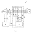
- FIG. 1 is a high level schematic diagram of an electromechanical power transfer system 2 configured for over potential protection according to a possible embodiment of the invention.
- the power transfer system 2 comprises a prime mover 4, such as a gas turbine engine, that couples to a multiphase AC dynamoelectric machine 6 by way of a drive shaft 8.
- the dynamoelectric machine 6 may comprise any machine with a controllable electrical potential or current output, such as a wound field synchronous machine (WFSM) or a controllable permanent magnet machine (PMM).
- WFSM wound field synchronous machine
- PMM controllable permanent magnet machine
- An example of a controllable PMM is found in EP 1829187 and US 2006/0226721 .
- the dynamoelectric machine 6 has a multiphase AC output on an AC power bus 10 to power at least one multiphase AC electrical load 12.
- a multiphase AC isolation contactor or generator control breaker (GCB) 14 inserted in the power bus 10 between the dynamoelectric machine and the electrical load 12 may serve to protect the power transfer system 2 from downstream electrical faults.
- the output of the dynamoelectric machine 6 is controllable by way of an electric field generated by control current that passes through a control coil 16 within the dynamoelectric machine 6.
- a control coil 6 is an exciter stator that receives exciter drive current.
- the control coil 6 receives control coil current.
- a multiphase AC potential sensor system 18 measures the electrical potentials on the power bus 10 to generate corresponding power bus potential signals on a sensor system signal bus 20.
- a generator or system control unit 22 receives the power bus potential signals by way of the sensor system signal bus 20 and compares them to a predetermined reference potential. The system control unit 22 then supplies a level of the control current to the control coil 16 by way of a control coil current bus 24 that maintains the potentials on the power bus at or near the predetermined reference potential under ordinary operating conditions.
- any transient peak potentials not controllable by the system control unit 22 may cause damage to the power transfer system 2 and the electrical load 12 without triggering the isolation contactor 14.
- An electronic multiphase AC shunt system 26 shunts current through the power bus 10 under such conditions to prevent such damaging transient peak potentials.
- the shunt system 26 comprises a multiphase AC rectifier system 28 that converts multiphase AC power on the power bus 10 to direct current (DC) power, with a positive DC rail potential on a positive DC rail 30 and a negative DC rail potential on a negative DC rail 32.
- the shunt system 26 also comprises a shunt system controller 34 that analyses characteristics of the power bus 10 by means of sensing the DC potentials on the positive DC rail 30 and the negative DC rail 32, compares the analysed power bus characteristics to predetermined power bus characteristics and if the difference approximates the predetermined power bus characteristics it generates a gate drive signal on a gate drive line 36.
- the analysed power bus characteristics may be electrical potentials on the power bus 10 derived by measuring the DC potentials on the positive DC rail 30 and the negative DC rail 32 and the predetermined power bus characteristics may be predetermined maximum peak potentials on the power bus 10.
- the analysed power bus characteristics may comprise present electrical potentials and rate of change in potentials on the power bus 10 derived by measuring the DC potentials and rate of change in the DC potentials on the positive DC rail 30 and the negative DC rail 32, or predicted maximum peak potentials on the power bus 10 based on the present electrical potentials and rate of change in the potentials on the power bus 10.
- the predetermined power bus characteristics may comprise predetermined maximum present electrical potentials and rate of change in potentials on the power bus 10 or maximum allowable predicted peak potentials on the power bus 10.
- the shunt system 26 additionally comprises a high speed electronic switch 38, such as an insulated gate bipolar transistor (IGBT) as shown in Figure 1 , or a metal oxide silicon field effect transistor (MOSFET) in lower power applications, which receives the gate drive signal on the gate drive line 36 and responds by shorting the positive gate rail 30 to the negative gate rail 32, thereby shunting the AC power on the power bus 10 by way of the multiphase AC rectifier system 28.
- a low pass filter system 40 that connects across the electronic switch 38, such as a low pass filter comprising resistors R1 and R2 with capacitor C1 shunting resistor R1 in Figure 1 , may be useful to reduce high frequency transients or noise caused by the switching action of the electronic switch 38.
- the shunt system controller 34 generates a shunt activation signal on a shunt activation signal line 42 whenever the shunt system controller 34 generates a gate drive signal to activate the electronic switch 38.
- the system control unit 22 receives the shunt activation signal on the shunt activation signal line 42 and responds by cutting or reducing control current on the control current bus 24 that supplies the control coil 16 in the dynamoelectric machine 6. This minimises the power that the shunt system 26 must shunt across the power bus 10 during sensed peak potentials that exceed the predetermined peak potential level. After a selected delay period, the system control unit 22 generates a shunt termination signal on a shunt termination line 44.
- the shunt system controller 34 receives the shunt termination signal on the shunt termination line 44 and responds by terminating the gate drive signal on the gate drive line 36, thereby deactivating the electronic switch 38 and terminating the shunt of the power bus 10 by the shunt system 26.
- the selected delay period may comprise a fixed period or a variable period, such as a variable period that varies in proportion to at least one of the analysed power bus characteristics, such as the rate of change in potentials on the power bus 10.
- a multiphase AC silicon controlled rectifier (SCR) or triode for AC (TRIAC) bridge may alternatively replace the rectifier system 28 and the electronic switch 38.
- the gate drive signal on the gate drive line 36 may drive such a SCR or TRIAC bridge to combine the functions of the rectifier system 28 and the electronic switch 38 if the positive DC rail 30 and the negative DC rail 32 short together to shunt the power bus phases and the shunt controller is responsive to the power bus potential signals on the sensor system signal bus 20.
- the shunt system 26 is separate from the system control unit 22.
- the system control unit 22 may comprise at least some of the hereinbefore-described components of the shunt system 26 so that the system control unit 22 itself controls or shunts the power bus 10.
- system control unit 22 may utilise the multiphase AC potential sensor system 18 to analyse the characteristics of the power bus 10 by means of sensing the electrical potentials on the power bus 10 directly.
Abstract
Description
- The invention relates to variable frequency electromechanical power transfer systems, and more particularly a means for protecting such power transfer systems from excessive peak electrical potentials whilst in a generating mode.
- Electromechanical power transfer systems, such as gas turbine-engine driven aeronautical electrical generation systems, generate large electrical potentials upon removal of large loads or faults by an electrical system circuit breaker or other means. Traditionally, electromechanical power transfer systems for aeronautical applications have operated in a constant frequency alternating current (AC) mode, generally employing an electrical power frequency of 400 Hz, and the electromagnetic saturation of a gas turbine driven dynamoelectric machine used for generating electrical power at that frequency and speed limited the resulting peak potentials. Aeronautical electrical loads have designs that tolerate and survive the peak potentials from the load and fault removals. Newer aeronautical electromechanical power transfer systems are migrating to a variable frequency AC mode of operation. These types of systems employ an electrical power frequency that may vary between 350 Hz and 800 Hz. At the lowest frequencies of such electromechanical power transfer systems, the peak potentials are essentially the same as conventional 400 Hz systems, but at the higher frequencies, the peak potential is substantially higher. Peak potential has a near linear relationship to the electrical power frequency in such systems. Consequently, aeronautical electrical loads may be subject to potentials approximately twice as large in systems operating in the variable frequency AC mode compared to operating in the constant frequency mode. This increased peak potential can damage such electrical loads.
- The invention generally comprises a method of protecting an electromechanical power transfer system from excessive peak electrical potentials, the power transfer system comprising a prime mover, a dynamoelectric machine coupled to the prime mover for generating multiphase alternating current (AC) power, and at least one multiphase AC electrical load coupled to the dynamoelectric machine by way of a multiphase AC power bus, the dynamoelectric machine having a control coil responsive to control current for varying power supplied to the electrical load, comprising the steps of: analysing electrical potentials on the power bus to generate analysed power bus characteristics; comparing the analysed power bus characteristics to predetermined power bus characteristics; simultaneously shunting power across the power bus and reducing control current to the control coil for the dynamoelectric machine when the analysed power bus characteristics approximate the predetermined power bus characteristics to reduce the measured electrical potentials; and simultaneously terminating the shunt of power across the power bus and restoring the level of control current to the control coil for the dynamoelectric machine after a selected delay period to automatically restore power to the electrical load.
-
-
Figure 1 is a high level schematic diagram of an electromechanical power transfer system configured for over potential protection according to a possible embodiment of the invention. -
Figure 1 is a high level schematic diagram of an electromechanical power transfer system 2 configured for over potential protection according to a possible embodiment of the invention. The power transfer system 2 comprises a prime mover 4, such as a gas turbine engine, that couples to a multiphase ACdynamoelectric machine 6 by way of a drive shaft 8. Thedynamoelectric machine 6 may comprise any machine with a controllable electrical potential or current output, such as a wound field synchronous machine (WFSM) or a controllable permanent magnet machine (PMM). An example of a controllable PMM is found inEP 1829187 andUS 2006/0226721 . Thedynamoelectric machine 6 has a multiphase AC output on anAC power bus 10 to power at least one multiphase ACelectrical load 12. A multiphase AC isolation contactor or generator control breaker (GCB) 14 inserted in thepower bus 10 between the dynamoelectric machine and theelectrical load 12 may serve to protect the power transfer system 2 from downstream electrical faults. The output of thedynamoelectric machine 6 is controllable by way of an electric field generated by control current that passes through acontrol coil 16 within thedynamoelectric machine 6. In the case of a WFSM, such acontrol coil 6 is an exciter stator that receives exciter drive current. In the case of a controllable PMM, thecontrol coil 6 receives control coil current. - A multiphase AC
potential sensor system 18 measures the electrical potentials on thepower bus 10 to generate corresponding power bus potential signals on a sensorsystem signal bus 20. A generator orsystem control unit 22 receives the power bus potential signals by way of the sensorsystem signal bus 20 and compares them to a predetermined reference potential. Thesystem control unit 22 then supplies a level of the control current to thecontrol coil 16 by way of a control coilcurrent bus 24 that maintains the potentials on the power bus at or near the predetermined reference potential under ordinary operating conditions. - However, particularly when the power transfer system 2 produces power on the
power bus 10 over a wide range of frequencies that may even exceed a two-to-one ratio, such as approximately 350 to 800 Hz, any transient peak potentials not controllable by thesystem control unit 22 may cause damage to the power transfer system 2 and theelectrical load 12 without triggering theisolation contactor 14. An electronic multiphaseAC shunt system 26 shunts current through thepower bus 10 under such conditions to prevent such damaging transient peak potentials. - The
shunt system 26 comprises a multiphaseAC rectifier system 28 that converts multiphase AC power on thepower bus 10 to direct current (DC) power, with a positive DC rail potential on apositive DC rail 30 and a negative DC rail potential on anegative DC rail 32. Theshunt system 26 also comprises ashunt system controller 34 that analyses characteristics of thepower bus 10 by means of sensing the DC potentials on thepositive DC rail 30 and thenegative DC rail 32, compares the analysed power bus characteristics to predetermined power bus characteristics and if the difference approximates the predetermined power bus characteristics it generates a gate drive signal on agate drive line 36. - For instance, the analysed power bus characteristics may be electrical potentials on the
power bus 10 derived by measuring the DC potentials on thepositive DC rail 30 and thenegative DC rail 32 and the predetermined power bus characteristics may be predetermined maximum peak potentials on thepower bus 10. Alternatively, the analysed power bus characteristics may comprise present electrical potentials and rate of change in potentials on thepower bus 10 derived by measuring the DC potentials and rate of change in the DC potentials on thepositive DC rail 30 and thenegative DC rail 32, or predicted maximum peak potentials on thepower bus 10 based on the present electrical potentials and rate of change in the potentials on thepower bus 10. Likewise, the predetermined power bus characteristics may comprise predetermined maximum present electrical potentials and rate of change in potentials on thepower bus 10 or maximum allowable predicted peak potentials on thepower bus 10. - The
shunt system 26 additionally comprises a high speed electronic switch 38, such as an insulated gate bipolar transistor (IGBT) as shown inFigure 1 , or a metal oxide silicon field effect transistor (MOSFET) in lower power applications, which receives the gate drive signal on thegate drive line 36 and responds by shorting thepositive gate rail 30 to thenegative gate rail 32, thereby shunting the AC power on thepower bus 10 by way of the multiphaseAC rectifier system 28. A low pass filter system 40 that connects across the electronic switch 38, such as a low pass filter comprising resistors R1 and R2 with capacitor C1 shunting resistor R1 inFigure 1 , may be useful to reduce high frequency transients or noise caused by the switching action of the electronic switch 38. - The
shunt system controller 34 generates a shunt activation signal on a shuntactivation signal line 42 whenever theshunt system controller 34 generates a gate drive signal to activate the electronic switch 38. Thesystem control unit 22 receives the shunt activation signal on the shuntactivation signal line 42 and responds by cutting or reducing control current on thecontrol current bus 24 that supplies thecontrol coil 16 in thedynamoelectric machine 6. This minimises the power that theshunt system 26 must shunt across thepower bus 10 during sensed peak potentials that exceed the predetermined peak potential level. After a selected delay period, thesystem control unit 22 generates a shunt termination signal on a shunt termination line 44. Theshunt system controller 34 receives the shunt termination signal on the shunt termination line 44 and responds by terminating the gate drive signal on thegate drive line 36, thereby deactivating the electronic switch 38 and terminating the shunt of thepower bus 10 by theshunt system 26. The selected delay period may comprise a fixed period or a variable period, such as a variable period that varies in proportion to at least one of the analysed power bus characteristics, such as the rate of change in potentials on thepower bus 10. - A multiphase AC silicon controlled rectifier (SCR) or triode for AC (TRIAC) bridge may alternatively replace the
rectifier system 28 and the electronic switch 38. In this case, the gate drive signal on thegate drive line 36 may drive such a SCR or TRIAC bridge to combine the functions of therectifier system 28 and the electronic switch 38 if thepositive DC rail 30 and thenegative DC rail 32 short together to shunt the power bus phases and the shunt controller is responsive to the power bus potential signals on the sensorsystem signal bus 20. - The entire shunting operation as hereinbefore described may easily complete within a 50 millisecond period, which is usually a dead bus requirement of the
electrical load 12 to be able to sustain and continue proper operation. Longer shunting times are also acceptable but may require theelectrical load 12 to recover from an abnormal dead bus time. As hereinbefore described, theshunt system 26 is separate from thesystem control unit 22. Alternatively, thesystem control unit 22 may comprise at least some of the hereinbefore-described components of theshunt system 26 so that thesystem control unit 22 itself controls or shunts thepower bus 10. If thesystem control unit 22 incorporates the functions of theshunt system controller 34, thesystem control unit 22 may utilise the multiphase ACpotential sensor system 18 to analyse the characteristics of thepower bus 10 by means of sensing the electrical potentials on thepower bus 10 directly. The hereinbefore-described embodiment of the invention is only an illustrative implementation of the invention wherein changes and substitutions of the various parts and arrangement thereof may be within the scope of the invention which is set forth in the attached claims.
Claims (15)
- A method of protecting an electromechanical power transfer system from excessive peak electrical potentials, the power transfer system comprising a prime mover, a dynamoelectric machine coupled to the prime mover for generating multiphase alternating current (AC) power, and at least one multiphase AC electrical load coupled to the dynamoelectric machine by way of a multiphase AC power bus, the dynamoelectric machine having a control coil responsive to control current for varying power supplied to the electrical load, comprising the steps of:analysing electrical potentials on the power bus to generate analysed power bus characteristics;comparing the analysed power bus characteristics to predetermined power bus characteristics;simultaneously shunting power across the power bus and reducing control current to the control coil for the dynamoelectric machine when the analysed power bus characteristics approximate the predetermined power bus characteristics to reduce the measured electrical potentials; andsimultaneously terminating the shunt of power across the power bus and restoring the level of control current to the control coil for the dynamoelectric machine after a selected delay period to automatically restore power to the electrical load.
- The method of Claim 1, wherein the dynamoelectric machine comprises a wound field synchronous machine (WFSM) and its control coil comprises its exciter stator.
- The method of Claim 1, wherein the dynamoelectric machine comprises a controllable permanent magnet machine (PMM).
- The method of Claim 1, 2 or 3, wherein the step of analysing electrical potentials on the power bus further comprises the steps of:rectifying the electrical potentials on the power bus to generate rectified power bus potentials; andanalysing the rectified power bus potentials.
- The method of Claim 4, wherein the step of comparing the analysed power bus characteristics to predetermined power bus characteristics comprises comparing the analysed rectified power bus potentials to a predetermined maximum rectified potential.
- The method of Claim 4 or 5, wherein the step of simultaneously shunting power across the power bus and reducing control current to the control coil for the dynamoelectric machine comprises shunting the rectified power bus potentials, and preferably wherein the step of simultaneously terminating the shunt of power across the power bus and restoring the level of control current to the control coil for the dynamoelectric machine comprises removing the shunt of the rectified power bus potentials.
- The method of any preceding Claim, wherein the step of shunting shunts when the analysed power bus characteristics approaches the predetermined power bus characteristics, or when the measured power bus characteristics exceeds the predetermined power bus characteristics.
- The method of any preceding Claim, wherein the step of analysing electrical potentials on the power bus further comprises measuring the rate of change in the electrical potentials.
- The method of Claim 8, wherein the analysed power bus characteristics comprise present electrical potentials and rate of change in potentials on the power bus and the predetermined power bus characteristics may comprise predetermined maximum present electrical potentials and rate of change in potentials on the power bus, or wherein the analysed power bus characteristics comprise predicted maximum peak potentials on the power bus on the present electrical potentials and rate of change in the potentials on the power bus and the predetermined power bus characteristics comprise maximum allowable predicted peak potentials on the power bus.
- The method of any preceding Claim, wherein the step of simultaneously terminating the shunt of power across the power bus and restoring the level of control current to the control coil for the dynamoelectric machine after a selected delay period comprises a delay period that varies in proportion to at least one of the analysed power bus characteristics, preferably the rate of change in potentials on the power bus.
- An electromechanical power transfer system comprising:a dynamoelectric machine adapted to be coupled to a prime mover to be driven thereby and coupled to a multiphase AC electrical load by way of a multiphase AC power bus for generating multiphase alternating current (AC) power for the electrical load, the dynamoelectric machine having a control coil responsive to control current for varying power supplied to the electrical load;a system control unit for varying the control coil current to maintain constant electrical potential levels on the power bus; andan electronic multiphase AC shunt system; whereinthe shunt system analyses electrical potentials on the power bus to generate analysed power bus characteristics, compares the analysed power bus characteristics to predetermined power bus characteristics, shunts power across the power bus and simultaneously generates a shunt activation signal when the analysed power bus characteristics approximates the predetermined power bus characteristics to reduce the measured electrical potentials;the system control unit receives the shunt activation signal and responds by reducing control current to the control coil for the dynamoelectric machine, then restores the level of control current to the control coil for the dynamoelectric machine after a predetermined period and generates a shunt termination signal; andthe shunt system receives the shunt termination signal and responds by terminating the shunt of power across the power bus to automatically restore power to the electrical load.
- The electromechanical power transfer system of Claim 11, wherein the shunt system comprises:a multiphase AC rectifier system for rectifying AC power on the power bus to generate direct current (DC) power with a positive potential level and a DC potential negative level; anda shunt system controller for measuring the generated positive and negative DC potential levels to analyse the power bus characteristics and comparing the analysed power bus characteristics with the predetermined power bus characteristics.
- The electromechanical power transfer system of Claim 12, wherein the shunt system further comprises an electronic switch and the shunt system controller generates a gate drive signal when the measured electrical potentials exceed the predetermined maximum electrical potential, the electronic switch receives the gate drive signal and responds by shunting the DC power across the rectifier system.
- The electromechanical power transfer system of Claim 13, wherein the shunt system controller terminates the gate drive signal to terminate the shunt of DC power across the rectifier system in response to receiving the shunt termination signal.
- The electromechanical power transfer system of Claim 11, wherein the shunt system comprises:a multiphase AC potential sensor system for measuring potentials on the power bus and generating corresponding power bus potential signals;a shunt system controller for measuring the generated power bus potential signals to analyse the power bus characteristics and comparing the analysed power bus characteristics with the predetermined power bus characteristics; anda multiphase AC shunt switch system for shunting AC power on the power bus.
Applications Claiming Priority (1)
| Application Number | Priority Date | Filing Date | Title |
|---|---|---|---|
| US11/940,342 US7518838B1 (en) | 2007-11-15 | 2007-11-15 | Protection of variable frequency power systems from excessive peak electrical potentials |
Publications (2)
| Publication Number | Publication Date |
|---|---|
| EP2061148A1 true EP2061148A1 (en) | 2009-05-20 |
| EP2061148B1 EP2061148B1 (en) | 2011-02-23 |
Family
ID=40377255
Family Applications (1)
| Application Number | Title | Priority Date | Filing Date |
|---|---|---|---|
| EP08253739A Active EP2061148B1 (en) | 2007-11-15 | 2008-11-17 | Protection of variable frequency power systems from excessive peak electrical potentials |
Country Status (2)
| Country | Link |
|---|---|
| US (1) | US7518838B1 (en) |
| EP (1) | EP2061148B1 (en) |
Families Citing this family (3)
| Publication number | Priority date | Publication date | Assignee | Title |
|---|---|---|---|---|
| US8922961B2 (en) * | 2009-09-25 | 2014-12-30 | Hamilton Sundstrand Corporation | Two-level lightning protection circuit |
| WO2014113420A1 (en) | 2013-01-17 | 2014-07-24 | Trane International Inc. | Variable prequency drive overvoltage protection |
| CN103326322A (en) * | 2013-06-14 | 2013-09-25 | 常熟市九洲电器设备有限公司 | Motor voltage protection and control circuit |
Citations (7)
| Publication number | Priority date | Publication date | Assignee | Title |
|---|---|---|---|---|
| JPS56132199A (en) * | 1980-03-19 | 1981-10-16 | Toshiba Corp | Controller for generator |
| US4786852A (en) * | 1986-07-18 | 1988-11-22 | Sundstrand Corporation | Inverter operated turbine engine starting system |
| EP1058366A2 (en) * | 1999-06-02 | 2000-12-06 | Eaton Corporation | Surge suppression network responsive to the rate of change of power disturbances |
| US20040008009A1 (en) * | 2002-03-20 | 2004-01-15 | Mitsuo Fukaya | Portable power supply |
| US20060208710A1 (en) * | 2005-03-21 | 2006-09-21 | Teleflex Canada Incorporated | Generator transient regulator |
| US20060226721A1 (en) | 2003-05-27 | 2006-10-12 | Dooley Kevin A | Saturation control of electric machine |
| EP1829187A1 (en) | 2004-11-26 | 2007-09-05 | Pratt & Whitney Canada Corp. | Saturation control of electric machine |
Family Cites Families (9)
| Publication number | Priority date | Publication date | Assignee | Title |
|---|---|---|---|---|
| US3571698A (en) * | 1969-02-17 | 1971-03-23 | Superior Electric Co | Low distortion automatic voltage regulator having controlled rectifiers |
| US4694187A (en) * | 1986-01-13 | 1987-09-15 | Westinghouse Electric Corp. | Electromechanical constant speed drive generating system |
| US4918592A (en) * | 1986-10-31 | 1990-04-17 | Honda Giken Kogyo Kabushiki Kaisha | Power regulating system for portable engine generator |
| US5528445A (en) * | 1994-09-23 | 1996-06-18 | General Electric Company | Automatic fault current protection for a locomotive propulsion system |
| CA2306531C (en) * | 1999-10-15 | 2011-07-12 | Wayne Ernest Conrad | Method and apparatus for delivering power to mechanical or electrical system |
| GB0227461D0 (en) * | 2002-11-25 | 2002-12-31 | Goodrich Control Sys Ltd | A method of and apparatus for detecting sensor loss in a generator control system |
| US7333316B1 (en) * | 2003-04-23 | 2008-02-19 | Littelfuse, Inc. | AC power line protection using thyristors |
| US7479756B2 (en) * | 2006-06-19 | 2009-01-20 | Rockwell Automation Technologies, Inc. | System and method for protecting a motor drive unit from motor back EMF under fault conditions |
| US7402965B2 (en) * | 2006-09-21 | 2008-07-22 | Rockwell Automation Technologies, Inc. | DC common bus self-protection method and system |
-
2007
- 2007-11-15 US US11/940,342 patent/US7518838B1/en active Active
-
2008
- 2008-11-17 EP EP08253739A patent/EP2061148B1/en active Active
Patent Citations (7)
| Publication number | Priority date | Publication date | Assignee | Title |
|---|---|---|---|---|
| JPS56132199A (en) * | 1980-03-19 | 1981-10-16 | Toshiba Corp | Controller for generator |
| US4786852A (en) * | 1986-07-18 | 1988-11-22 | Sundstrand Corporation | Inverter operated turbine engine starting system |
| EP1058366A2 (en) * | 1999-06-02 | 2000-12-06 | Eaton Corporation | Surge suppression network responsive to the rate of change of power disturbances |
| US20040008009A1 (en) * | 2002-03-20 | 2004-01-15 | Mitsuo Fukaya | Portable power supply |
| US20060226721A1 (en) | 2003-05-27 | 2006-10-12 | Dooley Kevin A | Saturation control of electric machine |
| EP1829187A1 (en) | 2004-11-26 | 2007-09-05 | Pratt & Whitney Canada Corp. | Saturation control of electric machine |
| US20060208710A1 (en) * | 2005-03-21 | 2006-09-21 | Teleflex Canada Incorporated | Generator transient regulator |
Also Published As
| Publication number | Publication date |
|---|---|
| EP2061148B1 (en) | 2011-02-23 |
| US7518838B1 (en) | 2009-04-14 |
Similar Documents
| Publication | Publication Date | Title |
|---|---|---|
| EP3125418B1 (en) | A method to detect or monitor the demagnetization of a magnet | |
| EP2482445B1 (en) | Independent, redundant overvoltage protection for a generator | |
| US20120281446A1 (en) | Preventing load dump overvoltages in synchronous rectifiers, | |
| US9270219B2 (en) | Voltage-controlled DC link for variable frequency generator excitation | |
| US9071051B2 (en) | Overvoltage protection unit with AC input current sensors | |
| US5805394A (en) | Overvoltage protection circuit for a generating system utilizing a fault current sensing Circuit in combination with a shunting circuit | |
| CN109687808B (en) | Permanent magnet synchronous motor end short-circuit protection system based on voltage feedforward | |
| CN102055393B (en) | Motor control apparatus | |
| EP2573891A2 (en) | Overvoltage protection using a link current sensor | |
| EP2045910B1 (en) | Starter/generator system with control to address a voltage rise | |
| JP2010063294A (en) | Power conversion apparatus | |
| US7518838B1 (en) | Protection of variable frequency power systems from excessive peak electrical potentials | |
| CN108291940B (en) | Method for detecting a fault in a generator unit | |
| CN108370230B (en) | multistage synchronous generator | |
| US9473062B2 (en) | Method for controlling a controlled switch operating the power supply of an electric motor | |
| US6664768B2 (en) | System and method for controlling load dump voltage of a permanent magnet (PM) alternator | |
| US9407083B1 (en) | Combined subtransient current suppression and overvoltage transient protection | |
| EP2549613B1 (en) | Overvoltage protection method and device | |
| US20030043610A1 (en) | Controller of AC machine | |
| CN220107569U (en) | Abnormal event detection unit and shaft belt power generation system with same | |
| CN211266457U (en) | Protection circuit of motor drive system and air conditioning equipment | |
| JP6431777B2 (en) | Power converter | |
| EP3267576A1 (en) | Controller and generator-motor starting method | |
| AU2021269391A1 (en) | An Alternator Stator Clamping Device |
Legal Events
| Date | Code | Title | Description |
|---|---|---|---|
| PUAI | Public reference made under article 153(3) epc to a published international application that has entered the european phase |
Free format text: ORIGINAL CODE: 0009012 |
|
| AK | Designated contracting states |
Kind code of ref document: A1 Designated state(s): AT BE BG CH CY CZ DE DK EE ES FI FR GB GR HR HU IE IS IT LI LT LU LV MC MT NL NO PL PT RO SE SI SK TR |
|
| AX | Request for extension of the european patent |
Extension state: AL BA MK RS |
|
| 17Q | First examination report despatched |
Effective date: 20090921 |
|
| 17P | Request for examination filed |
Effective date: 20090821 |
|
| AKX | Designation fees paid |
Designated state(s): FR GB |
|
| REG | Reference to a national code |
Ref country code: DE Ref legal event code: 8566 |
|
| GRAP | Despatch of communication of intention to grant a patent |
Free format text: ORIGINAL CODE: EPIDOSNIGR1 |
|
| RIN1 | Information on inventor provided before grant (corrected) |
Inventor name: LEMBERG, NICHOLAS ALLEN Inventor name: OLDENBURG, WAYNE H. |
|
| GRAS | Grant fee paid |
Free format text: ORIGINAL CODE: EPIDOSNIGR3 |
|
| GRAA | (expected) grant |
Free format text: ORIGINAL CODE: 0009210 |
|
| AK | Designated contracting states |
Kind code of ref document: B1 Designated state(s): FR GB |
|
| REG | Reference to a national code |
Ref country code: GB Ref legal event code: FG4D |
|
| PLBE | No opposition filed within time limit |
Free format text: ORIGINAL CODE: 0009261 |
|
| STAA | Information on the status of an ep patent application or granted ep patent |
Free format text: STATUS: NO OPPOSITION FILED WITHIN TIME LIMIT |
|
| 26N | No opposition filed |
Effective date: 20111124 |
|
| REG | Reference to a national code |
Ref country code: FR Ref legal event code: PLFP Year of fee payment: 8 |
|
| REG | Reference to a national code |
Ref country code: FR Ref legal event code: PLFP Year of fee payment: 9 |
|
| REG | Reference to a national code |
Ref country code: FR Ref legal event code: PLFP Year of fee payment: 10 |
|
| REG | Reference to a national code |
Ref country code: FR Ref legal event code: PLFP Year of fee payment: 11 |
|
| P01 | Opt-out of the competence of the unified patent court (upc) registered |
Effective date: 20230522 |
|
| PGFP | Annual fee paid to national office [announced via postgrant information from national office to epo] |
Ref country code: GB Payment date: 20231019 Year of fee payment: 16 |
|
| PGFP | Annual fee paid to national office [announced via postgrant information from national office to epo] |
Ref country code: FR Payment date: 20231020 Year of fee payment: 16 |