EP2061116A1 - Improvement in the field of energy storage elements - Google Patents
Improvement in the field of energy storage elements Download PDFInfo
- Publication number
- EP2061116A1 EP2061116A1 EP08168943A EP08168943A EP2061116A1 EP 2061116 A1 EP2061116 A1 EP 2061116A1 EP 08168943 A EP08168943 A EP 08168943A EP 08168943 A EP08168943 A EP 08168943A EP 2061116 A1 EP2061116 A1 EP 2061116A1
- Authority
- EP
- European Patent Office
- Prior art keywords
- voltage
- storage units
- cells
- unit
- series
- Prior art date
- Legal status (The legal status is an assumption and is not a legal conclusion. Google has not performed a legal analysis and makes no representation as to the accuracy of the status listed.)
- Withdrawn
Links
Images

Classifications
-
- H—ELECTRICITY
- H01—ELECTRIC ELEMENTS
- H01M—PROCESSES OR MEANS, e.g. BATTERIES, FOR THE DIRECT CONVERSION OF CHEMICAL ENERGY INTO ELECTRICAL ENERGY
- H01M10/00—Secondary cells; Manufacture thereof
- H01M10/42—Methods or arrangements for servicing or maintenance of secondary cells or secondary half-cells
- H01M10/44—Methods for charging or discharging
- H01M10/441—Methods for charging or discharging for several batteries or cells simultaneously or sequentially
-
- B—PERFORMING OPERATIONS; TRANSPORTING
- B60—VEHICLES IN GENERAL
- B60L—PROPULSION OF ELECTRICALLY-PROPELLED VEHICLES; SUPPLYING ELECTRIC POWER FOR AUXILIARY EQUIPMENT OF ELECTRICALLY-PROPELLED VEHICLES; ELECTRODYNAMIC BRAKE SYSTEMS FOR VEHICLES IN GENERAL; MAGNETIC SUSPENSION OR LEVITATION FOR VEHICLES; MONITORING OPERATING VARIABLES OF ELECTRICALLY-PROPELLED VEHICLES; ELECTRIC SAFETY DEVICES FOR ELECTRICALLY-PROPELLED VEHICLES
- B60L50/00—Electric propulsion with power supplied within the vehicle
- B60L50/40—Electric propulsion with power supplied within the vehicle using propulsion power supplied by capacitors
-
- H—ELECTRICITY
- H02—GENERATION; CONVERSION OR DISTRIBUTION OF ELECTRIC POWER
- H02J—CIRCUIT ARRANGEMENTS OR SYSTEMS FOR SUPPLYING OR DISTRIBUTING ELECTRIC POWER; SYSTEMS FOR STORING ELECTRIC ENERGY
- H02J7/00—Circuit arrangements for charging or depolarising batteries or for supplying loads from batteries
- H02J7/0013—Circuit arrangements for charging or depolarising batteries or for supplying loads from batteries acting upon several batteries simultaneously or sequentially
- H02J7/0014—Circuits for equalisation of charge between batteries
- H02J7/0016—Circuits for equalisation of charge between batteries using shunting, discharge or bypass circuits
-
- H—ELECTRICITY
- H02—GENERATION; CONVERSION OR DISTRIBUTION OF ELECTRIC POWER
- H02J—CIRCUIT ARRANGEMENTS OR SYSTEMS FOR SUPPLYING OR DISTRIBUTING ELECTRIC POWER; SYSTEMS FOR STORING ELECTRIC ENERGY
- H02J7/00—Circuit arrangements for charging or depolarising batteries or for supplying loads from batteries
- H02J7/34—Parallel operation in networks using both storage and other dc sources, e.g. providing buffering
- H02J7/345—Parallel operation in networks using both storage and other dc sources, e.g. providing buffering using capacitors as storage or buffering devices
-
- Y—GENERAL TAGGING OF NEW TECHNOLOGICAL DEVELOPMENTS; GENERAL TAGGING OF CROSS-SECTIONAL TECHNOLOGIES SPANNING OVER SEVERAL SECTIONS OF THE IPC; TECHNICAL SUBJECTS COVERED BY FORMER USPC CROSS-REFERENCE ART COLLECTIONS [XRACs] AND DIGESTS
- Y02—TECHNOLOGIES OR APPLICATIONS FOR MITIGATION OR ADAPTATION AGAINST CLIMATE CHANGE
- Y02E—REDUCTION OF GREENHOUSE GAS [GHG] EMISSIONS, RELATED TO ENERGY GENERATION, TRANSMISSION OR DISTRIBUTION
- Y02E60/00—Enabling technologies; Technologies with a potential or indirect contribution to GHG emissions mitigation
- Y02E60/10—Energy storage using batteries
-
- Y—GENERAL TAGGING OF NEW TECHNOLOGICAL DEVELOPMENTS; GENERAL TAGGING OF CROSS-SECTIONAL TECHNOLOGIES SPANNING OVER SEVERAL SECTIONS OF THE IPC; TECHNICAL SUBJECTS COVERED BY FORMER USPC CROSS-REFERENCE ART COLLECTIONS [XRACs] AND DIGESTS
- Y02—TECHNOLOGIES OR APPLICATIONS FOR MITIGATION OR ADAPTATION AGAINST CLIMATE CHANGE
- Y02T—CLIMATE CHANGE MITIGATION TECHNOLOGIES RELATED TO TRANSPORTATION
- Y02T10/00—Road transport of goods or passengers
- Y02T10/60—Other road transportation technologies with climate change mitigation effect
- Y02T10/70—Energy storage systems for electromobility, e.g. batteries
Definitions
- the present invention relates to the field of electrical storage elements, in particular energy storage elements of the battery type or the supercapacitor type. These are also known as super- or ultra-capacitors or UCAP and are particularly intended for high power applications.
- the present invention relates more particularly to the charging and discharging of such elements.
- the applications of the present invention are, for example, in the field of transport (hybrid vehicles, trams, buses, etc.), power supply (wind turbines) or even more particularly in areas where peaks in electrical consumption can need to supplement the energy provided by a battery or network.
- the supercapacitors currently marketed typically consist of a cylindrical element formed by the winding on itself of a sheet consisting of an aluminum sheet forming an anode, a paper separator and another sheet of paper. aluminum forming a cathode.
- the sheets forming the anode and the cathode typically undergo a surface treatment to promote the formation of a thin layer of alumina and especially the adhesion of an active layer, such as for example a carbon foam.
- the element thus formed is then impregnated with an electrolyte and the assembly is enclosed in a sealed housing in order to prevent evaporation of the electrolyte by providing, of course, means for connecting the anode and the cathode to an electric circuit.
- an electrical storage unit comprising at least one UCAP is incorporated in a network whose consumers require fixed regulated voltages.
- this network may include another storage unit, such as an electrochemical battery, capable of providing a voltage for example of the order of 13 volts.
- this object is achieved by the provision of elementary cells intended to be associated with each other, each elementary cell comprising a power line connecting two connection terminals, an electrical storage unit connected to the terminals of the line. power through at least one switch and a control line for controlling the one or more switches and adapted for connection to other elementary cell control lines. It can also be advantageously provided means for forcing a switch in the disconnected position.
- the electrical storage unit comprises at least one supercapacitor and / or at least one electrochemical battery. It should be noted that the storage unit can be constituted in particular by the series or parallel association of a plurality of supercapacitors and / or batteries. When the storage unit comprises at least one supercapacitor, means for limiting the voltage across the supercapacitors may also be provided.
- the control line may be a wired line or a wireless line, the control being then operated by electromagnetic waves such as radio or light signals.
- the command line can be integrated into the power line.
- the elementary cell further comprises a polarity inverter placed between the storage unit. electrical and power line and associated with a command line.
- the switches may be, for example, constituted by electronically controlled switches or electromechanical relays.
- Each elementary cell is, according to the invention, considered as an independent energy reservoir, which can either be in series or disconnected, depending on the voltage requirements, charge mode and discharge mode.
- the cells are used to form modules obtained by placing in series and / or in parallel the power lines of at least two elementary cells as defined above, all the cells of the same module being associated with the same command line.
- the command line, and therefore the set of switches - is controlled by a central unit.
- This central unit can also manage the detection of the number of cells present in the module, which is particularly advantageous for applications requiring a large number of cells and / or a fluctuating number of cells.
- Each switch is designed to respond to a command that is specific to it. This can be achieved for example by means of voltage thresholds or pulse trains.
- the module constituted by putting in series a plurality of elementary cells makes it possible to charge all the electrical storage units progressively, by connecting a module comprising n cells each having a maximum unit voltage U n, max less than a source of voltage U, and operating a series of operations de-switching and re-switching in turn a series of unit cells so as to progressively increment the load of each of the unit cells, to a level close to but less than its voltage unitary maximum U n, max .
- the sum of the unit voltages of the storage units may become greater than the voltage U.
- the voltage source U is preferably smaller than the sum of the voltages U n, max , but may possibly be greater if the cells are equipped with means for limiting the applied voltage. to each cell.
- FIGS. Figures 1A and 1B A basic diagram of an elementary cell according to the invention is shown in FIGS. Figures 1A and 1B .
- the cell is constituted by an electrical storage unit 1, connected in parallel between two terminals 2, 3 of a power line 4, by interposing at least one switch 5.
- the switch is a 2-position switch: S and BP, the terminal corresponding to the BP position being connected to the power line.
- S the terminal corresponding to the BP position
- BP the terminal connected to the power line.
- the position S corresponds to the serialization of the storage unit.
- a voltage limiting system may be provided to limit the voltage across this storage unit.
- the BP position may be forced so as to isolate temporarily or permanently a cell without preventing the operation of a module associating several cells.
- This elementary cell further comprises a command line C for placing the switch in one of the 2 positions according to an order sent by the command line.
- This control line is provided at its ends with means of the socket type, plug, to associate two control lines in series as will be seen later.
- the terminals at the ends of a power line allow cells to be connected in series, as shown for example in FIG. figure 2 , with a module constituted by the series assembly of 3 elementary cells, denoted from bottom to top C1, C2 and C3.
- a module constituted by the series assembly of 3 elementary cells, denoted from bottom to top C1, C2 and C3.
- all the cells of the same module are controlled by a single command line, which assumes different levels of control for individual recognition by each cell as will be detailed below.
- it is also possible to keep an individual command line for each cell which makes it possible to use all identical switches, but adds a number of power lines to the network.
- full bypass mode In the mode of figure 2-A , called "full bypass mode", all storage units of the elementary cells are disconnected and the voltage across the module is zero.
- the voltage at the terminals of the 3-cell module will be between 0 and 2.7 Volts, depending on the load level of the capacity of the cell in series.
- the voltage across the module With two cells in series, always depending on the load level of the capacity of the cells put in series, the voltage across the module will be between 0 and 5.4 Volts. And with the 3 cells mounted in series as in the case illustrated in the Figure 2C , the voltage across the module will vary between 0 and 8.1 volts.
- all the cells use the same command line on which the control signal is sent and to which one or more cells will respond. This can be achieved in particular by control signals consisting of voltage thresholds.
- Another variant consists of pulse trains, which allows individual control with a single command line. This variant, like the first variant, allows more flexibility in the control of the cells.
- each cell having a UCAP capable of being charged at most to 2.7 Volts, and whose maximum nominal voltage is 2.5V.
- the 10 UCAP we will thus load all the UCAP at 1/10 the voltage of the battery, or 1.25 Volts. This value represents less than 50% of the maximum rated voltage.
- the object of the sequence of the commutations is to allow the continuation of the load of the cells
- the 12.5 volts of the battery will be distributed on the 9 cells which remain in series, which therefore see their load increase to correspond to a unit voltage of 1.39 volts.
- the load of all the cells at 1.39 Volts is again equalized.
- the voltage across the module is now 13.89 volts.
- Table I gives an example of a possible succession of switches ensuring the charging of 10 Ucaps with a battery at 12.5 Volts in the case where the cells have a separate individual command. As shown in the table, the final load voltage of the module is 25V for a battery voltage of 12.5V.
- the disconnection of the C8 cell also supposes a disconnection of the C9 and C10 cells. This is why it is advantageous to provide balancing phases during which all or part of the module is isolated from the power source and all or part of the cells are again put in series, so as to homogenize the voltage of any or part of the cells of the module. In practice the balancing phases are to be reduced to be done only when the energies between the cells are significantly different to require a balancing phase.
- a method for charging a set of n electrical storage units each having a maximum unit voltage u n, max characterized in that that a number j (with j less than or equal to n), storage units are put in series to be powered under the voltage U, the number j being adapted to the voltage U and the charge level of the storage units a so that the sum of the unit voltages of the storage units is less than or equal to U and that no storage unit exceeds its maximum unit voltage.
- the loading under voltage U of the storage units can be advantageously continued by excluding i storage units, with i such that the sum of the unit voltages of the storage units is less than or equal to U and that no storage unit exceeds its maximum unit voltage.
- Each exclusion phase of one or more storage units may be preceded and / or followed by one (or more) phase of electrical isolation and serialization of all or part of the n storage units so as to balance the load between all or part of the n storage units
- n-unit module When now the n-unit module is used as a power source, there will of course be a decrease in the state of the cell charges - and it is desirable to regulate the output voltage of the module around a value. setpoint, fixed or modulated, to compensate for the discharge, or voltage drop, dynamic cells.
- the scheme proposed at figure 3 illustrates again the case of 10 Ucaps operating in voltage regulation at 12.5V. Initially, Ucaps are charged at 2.5 volts. With 5 Ucaps in series, the desired setpoint voltage of 12.5 V is available. (Point 1).
- Table III - while in Table I - illustrates a possible implementation of this mode of discharge, assuming 10 Ucaps supplying a regulated load of 12.5V (between 11.25V and 13.75V) initially all charged at 2.5 V, each cell being provided with a single or separate command.
- the case of figure 3 describes a voltage threshold control.
- Table IV - while in Table II - is likewise an illustrative example of the discharge mode with cells provided with independent control, again to provide a regulated load of 12.5V (between 11.25V and 13.50V). ) from a module with all Ucaps initially loaded at 2.5 V.
- the invention thus also proposes a method for regulating the supply of a setpoint voltage U from n storage units, characterized in that storage units are placed in series so that the sum of the The unit voltages of the storage units are close to U, and one or more storage units are added in series as the storage units are discharged in order to maintain a voltage close to the set voltage U.
- Each addition of one or more units may be preceded or followed by a phase of electrical isolation and serialization of all or part of n storage units so as to balance the load between all or part of the n storage units.
- the unit cell further comprises a polarity inverter, with the addition of a first line of currents
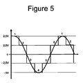
- This type of switching makes it possible to generate different types of electrical signals, for example a sinusoid as illustrated by FIG. figure 5 .
Abstract
Description
La présente invention concerne le domaine des éléments de stockage électrique, notamment des éléments de stockage d'énergie du type batteries ou du type supercondensateurs. Ces derniers sont également connus sous le terme de super- ou ultra-capacités ou encore UCAP et sont particulièrement destinés aux applications de forte puissance. La présente invention concerne plus particulièrement la charge et la décharge de tels éléments.The present invention relates to the field of electrical storage elements, in particular energy storage elements of the battery type or the supercapacitor type. These are also known as super- or ultra-capacitors or UCAP and are particularly intended for high power applications. The present invention relates more particularly to the charging and discharging of such elements.
Les applications de la présente invention sont, par exemple, dans le domaine des transports (véhicules hybrides, tramways, bus, etc.), de l'alimentation électrique (éoliennes) ou encore plus particulièrement dans des domaines où des pointes de consommation électriques peuvent nécessiter de supplémenter l'énergie fournie par une batterie ou un réseau.The applications of the present invention are, for example, in the field of transport (hybrid vehicles, trams, buses, etc.), power supply (wind turbines) or even more particularly in areas where peaks in electrical consumption can need to supplement the energy provided by a battery or network.
La technologie de stockage d'énergie par des supercondensateurs repose sur le principe de fonctionnement des condensateurs classiques, et offre ainsi des performances en densités d'énergie relativement faibles mais avec une capacité au stockage / déstockage en fortes puissances. Ces supercondensateurs s'apparent ainsi fonctionnellement aux batteries électrochimiques qui équipent notamment les véhicules automobiles. Les supercondensateurs supportent un nombre de cycles de charge et de décharge très supérieur à celui des batteries conventionnelles, les spécialisant dans les applications requérant des sources de puissance élevée sur des temps courts. La spécificité d'une supercapacité est d'être un système d'accumulation de tension capacitif avec, comme pour tout condensateur, la quantité de charge électrostatique Q reliée à la tension U par l'équation Q = CU2/2.Supercapacitor energy storage technology is based on the operating principle of conventional capacitors, and thus offers relatively low power density performance but with high power storage / retrieval capability. These supercapacitors are thus functionally related to electrochemical batteries that equip including motor vehicles. Supercapacitors withstand much higher charge and discharge cycles than conventional batteries, specializing in applications requiring high power sources over short periods of time. The specificity of a supercapacity is to be a capacitive voltage accumulation system with, as for any capacitor, the amount of electrostatic charge Q connected to the voltage U by the equation Q = CU2 / 2.
Les supercondensateurs actuellement commercialisés sont typiquement constitués d'un élément cylindrique formé par l'enroulement sur lui-même d'un feuillet composé d'une feuille d'aluminium formant une anode, d'un séparateur en papier et d'une autre feuille d'aluminium formant une cathode. Les feuilles formant l'anode et la cathode subissant typiquement un traitement de surface pour favoriser la formation d'une fine couche d'alumine et surtout l'adhésion d'une couche active, comme par exemple une mousse de carbone. L'élément ainsi formé est ensuite imprégné d'un électrolyte et l'ensemble est enfermé dans un boitier étanche afin d'éviter l'évaporation de l'électrolyte en prévoyant, bien sûr, des moyens pour connecter l'anode et la cathode à un circuit électrique.The supercapacitors currently marketed typically consist of a cylindrical element formed by the winding on itself of a sheet consisting of an aluminum sheet forming an anode, a paper separator and another sheet of paper. aluminum forming a cathode. The sheets forming the anode and the cathode typically undergo a surface treatment to promote the formation of a thin layer of alumina and especially the adhesion of an active layer, such as for example a carbon foam. The element thus formed is then impregnated with an electrolyte and the assembly is enclosed in a sealed housing in order to prevent evaporation of the electrolyte by providing, of course, means for connecting the anode and the cathode to an electric circuit.
Du fait de cette technologie de construction par enroulement de films minces, la tension unitaire maximum d'une UCAP est aujourd'hui limitée à environ 2,7 Volts.Because of this thin film winding construction technology, the maximum unit voltage of a UCAP is now limited to about 2.7 volts.
Or, pour de nombreuses utilisations et notamment les applications dans le domaine de l'automobile, une unité de stockage électrique comportant au moins une UCAP est incorporée dans un réseau dont les consommateurs demandent des tensions régulées fixes. De plus, ce réseau peut comporter une autre unité de stockage, telle une batterie électrochimique, capable de fournir une tension par exemple de l'ordre de 13 Volts.However, for many uses and particularly applications in the automotive field, an electrical storage unit comprising at least one UCAP is incorporated in a network whose consumers require fixed regulated voltages. In addition, this network may include another storage unit, such as an electrochemical battery, capable of providing a voltage for example of the order of 13 volts.
Pour pouvoir charger (ou plus généralement élever, abaisser ou réguler la tension lors de la charge ou de la décharge), il est alors nécessaire de munir le réseau d'un ou plusieurs convertisseurs de tension de type DC/DC. Ces convertisseurs renchérissent fortement le coût d'une installation. De plus, ils complexifient la conception du réseau et la gestion des différentes unités consommatrices et/ou productrices d'électricité. Par ailleurs, ces convertisseurs doivent trouver une place, dans un espace qui peut être compté comme l'est notamment le volume sous capot dans un véhicule automobile. Il serait donc souhaitable de pouvoir simplifier l'architecture des réseaux, en autorisant notamment la suppression de ces convertisseurs de tension de type DC/DC.In order to be able to charge (or more generally to raise, lower or regulate the voltage during charging or discharging), it is then necessary to provide the network with one or more DC / DC type voltage converters. These converters greatly increase the cost of an installation. In addition, they complicate the network design and the management of the different units that consume and / or produce electricity. Moreover, these converters must find a place in a space that can be counted as is particularly the volume under hood in a motor vehicle. It would therefore be desirable to be able to simplify the network architecture, in particular by allowing the removal of these DC / DC type voltage converters.
Selon l'invention, ce but est atteint par la fourniture de cellules élémentaires destinées à être associées les unes avec les autres, chaque cellule élémentaire comportant une ligne de puissance reliant deux bornes de connexion, une unité de stockage électrique reliée aux bornes de la ligne de puissance par l'intermédiaire d'au moins un commutateur et d'une ligne de commande pour commander le ou les commutateurs et adaptée à la connexion à d'autres lignes de commande de cellules élémentaires. Il peut par ailleurs être avantageusement prévu des moyens pour forcer un commutateur en position déconnectée.According to the invention, this object is achieved by the provision of elementary cells intended to be associated with each other, each elementary cell comprising a power line connecting two connection terminals, an electrical storage unit connected to the terminals of the line. power through at least one switch and a control line for controlling the one or more switches and adapted for connection to other elementary cell control lines. It can also be advantageously provided means for forcing a switch in the disconnected position.
Selon certaines caractéristiques de l'invention, l'unité de stockage électrique comporte au moins un supercondensateur et/ou au moins une batterie électrochimique. Il est à noter que l'unité de stockage peut être notamment constituée par l'association en série ou en parallèle d'une pluralité de supercondensateurs et/ou de batteries. Lorsque l'unité de stockage comporte au moins un supercondensateur, des moyens de limitation de la tension aux bornes des supercondensateurs peuvent également être prévus.According to certain features of the invention, the electrical storage unit comprises at least one supercapacitor and / or at least one electrochemical battery. It should be noted that the storage unit can be constituted in particular by the series or parallel association of a plurality of supercapacitors and / or batteries. When the storage unit comprises at least one supercapacitor, means for limiting the voltage across the supercapacitors may also be provided.
La ligne de commande peut être une ligne filaire ou une ligne sans fil, la commande étant alors opérée par des ondes électromagnétiques comme par exemple des signaux radio ou lumineux. Par ailleurs la ligne de commande peut être intégrée à la ligne de puissance.The control line may be a wired line or a wireless line, the control being then operated by electromagnetic waves such as radio or light signals. In addition, the command line can be integrated into the power line.
Dans un mode de réalisation tout particulièrement avantageux de l'invention, la cellule élémentaire comporte de plus un inverseur de polarité placé entre l'unité de stockage électrique et la ligne de puissance et associé à une ligne de commande.In a particularly advantageous embodiment of the invention, the elementary cell further comprises a polarity inverter placed between the storage unit. electrical and power line and associated with a command line.
Les commutateurs peuvent être, par exemple, constitués par des interrupteurs à commande électronique ou des relais électromécaniques.The switches may be, for example, constituted by electronically controlled switches or electromechanical relays.
Chaque cellule élémentaire est, selon l'invention, considérée comme un réservoir d'énergie indépendant, que l'on peut soit mettre en série, soit déconnecter, en fonction des besoins en tension, en mode charge et en mode décharge.Each elementary cell is, according to the invention, considered as an independent energy reservoir, which can either be in series or disconnected, depending on the voltage requirements, charge mode and discharge mode.
Ainsi, les cellules sont utilisées pour former des modules obtenus par la mise en série et/ou en parallèle des lignes de puissance d'au moins deux cellules élémentaires telles que définies précédemment, l'ensemble des cellules d'un même module étant associées à la même ligne de commande.Thus, the cells are used to form modules obtained by placing in series and / or in parallel the power lines of at least two elementary cells as defined above, all the cells of the same module being associated with the same command line.
La ligne de commande, et donc l'ensemble des commutateurs - est contrôlée par une unité centrale. Cette unité centrale peut également gérer la détection du nombre de cellules présentes dans le module, ce qui est tout particulièrement avantageux pour les applications nécessitant un grand nombre de cellules et/ou un nombre fluctuant de cellules.The command line, and therefore the set of switches - is controlled by a central unit. This central unit can also manage the detection of the number of cells present in the module, which is particularly advantageous for applications requiring a large number of cells and / or a fluctuating number of cells.
Chaque commutateur est conçu pour répondre à une commande qui lui est spécifique. Ceci peut être réalisé par exemple par l'intermédiaire de seuils de tension ou de trains d'impulsions.Each switch is designed to respond to a command that is specific to it. This can be achieved for example by means of voltage thresholds or pulse trains.
Le module constitué par la mise en série d'une pluralité de cellules élémentaires permet de charger l'ensemble des unités de stockage électrique progressivement, en reliant un module comportant n cellules ayant chacune une tension unitaire maximale Un,max inférieure à une source de tension U, et en opérant une série d'opération dé-commutant et re-commutant tour à tour une série de cellules unitaires de façon à incrémenter progressivement la charge de chacune des cellules unitaires, jusqu'à un niveau proche mais inférieur à sa tension unitaire maximale Un,max. La somme des tensions unitaires des unités de stockages pouvant devenir supérieure à la tension U.The module constituted by putting in series a plurality of elementary cells makes it possible to charge all the electrical storage units progressively, by connecting a module comprising n cells each having a maximum unit voltage U n, max less than a source of voltage U, and operating a series of operations de-switching and re-switching in turn a series of unit cells so as to progressively increment the load of each of the unit cells, to a level close to but less than its voltage unitary maximum U n, max . The sum of the unit voltages of the storage units may become greater than the voltage U.
Lorsque les unités de stockage des cellules élémentaires sont du type UCAPs, la source de tension U est de préférence inférieure à la somme des tensions Un,max, mais peut être éventuellement supérieure si les cellules sont équipées de moyens de limitation de la tension appliquée à chaque cellule.When the storage units of the elementary cells are of the UCAPs type, the voltage source U is preferably smaller than the sum of the voltages U n, max , but may possibly be greater if the cells are equipped with means for limiting the applied voltage. to each cell.
D'autres avantages et particularités de l'invention ressortent de la description de modes de réalisation faite ci-après en référence aux dessins annexés dans lesquels :
- La
figure 1 illustre une cellule unitaire dont l'unité de stockage peut être une Ucapfig 1A ou une batteriefig 1B . - La
figure 2 illustre un module de 3 cellules et son mode de commutation. - La
figure 3 illustre le fonctionnement d'un pack de 10 cellules en mode de régulation de tension en décharge, autour d'une tension de 12,5V. - La
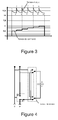
figure 4 illustre une cellule unitaire équipée d'un inverseur de tension. - La
figure 5 illustre une sinusoïde simple obtenue avec deux cellules montées en série et équipées chacune d'un inverseur de tension.
- The
figure 1 illustrates a unit cell whose storage unit can be a Ucapfig 1A or a batteryfig 1B . - The
figure 2 illustrates a 3-cell module and its switching mode. - The
figure 3 illustrates the operation of a pack of 10 cells in discharge voltage regulation mode, around a voltage of 12.5V. - The
figure 4 illustrates a unit cell equipped with a voltage inverter. - The
figure 5 illustrates a simple sinusoid obtained with two cells connected in series and each equipped with a voltage inverter.
Un schéma de principe d'une cellule élémentaire selon l'invention est représenté aux
Dans le mode de réalisation proposé sur oe schéma, le commutateur est un interrupteur à 2 positions : S et BP, la borne correspondant à la position BP étant reliée à la ligne de puissance. Ainsi, lorsque l'interrupteur est en position BP, le courant peut passer d'une borne à l'autre de la ligne de puissance mais l'unité de stockage électrique est déconnectée. La position S correspond à la mise en série de l'unité de stockage. Lorsque l'unité de stockage est constituée par une UCAP, un système de limitation de tension pourra être prévu pour limiter la tension aux bornes de cette unité de stockage.In the embodiment proposed in this scheme, the switch is a 2-position switch: S and BP, the terminal corresponding to the BP position being connected to the power line. Thus, when the switch is in the BP position, the current can pass from one terminal to the other of the power line but the electrical storage unit is disconnected. The position S corresponds to the serialization of the storage unit. When the storage unit is constituted by a UCAP, a voltage limiting system may be provided to limit the voltage across this storage unit.
Dans une variante optionnelle de l'invention, non représentée ici, la position BP peut être forcée de manière à isoler temporairement ou définitivement une cellule sans empêcher le fonctionnement d'un module associant plusieurs cellules.In an optional variant of the invention, not shown here, the BP position may be forced so as to isolate temporarily or permanently a cell without preventing the operation of a module associating several cells.
Cette cellule élémentaire comporte de plus une ligne de commande C pour placer l'interrupteur dans l'une des 2 positions en fonction d'un ordre envoyé par la ligne de commande. Cette ligne de commande est munie à ses extrémités de moyens de type prise femelle, prise mâle, pour associer deux lignes de commande en série comme il sera vu plus loin.This elementary cell further comprises a command line C for placing the switch in one of the 2 positions according to an order sent by the command line. This control line is provided at its ends with means of the socket type, plug, to associate two control lines in series as will be seen later.
Les bornes aux extrémités d'une ligne de puissance, ici schématisées sous la forme d'une borne femelle pour le pôle négatif et d'une borne mâle pour le pôle positif permettent de monter en série des cellules, comme illustré par exemple à la
Dans le mode de la
Si maintenant on commande le commutateur d'une des cellules, (par exemple de la cellule C1 dans le mode illustré à la
Avec deux cellules mises en série, toujours en fonction du niveau de charge de la capacité des cellules mises en série, la tension aux bornes du module sera comprise entre 0 et 5,4 Volts. Et avec les 3 cellules montées en série comme dans le cas illustré à la
Pour faire varier le nombre de cellules mises en série dans un module, il faut pouvoir commander chaque commutateur plaçant l'unité de stockage en série (S) ou déconnectée (BP).To vary the number of cells placed in series in a module, it must be possible to control each switch placing the storage unit in series (S) or disconnected (BP).
Selon l'invention, toutes les cellules utilisent la même ligne de commande sur laquelle le signal de commande est envoyé et auquel une ou plusieurs cellules vont répondre. Ceci peut être réalisé notamment par des signaux de commande constitués par des seuils de tension.According to the invention, all the cells use the same command line on which the control signal is sent and to which one or more cells will respond. This can be achieved in particular by control signals consisting of voltage thresholds.
Une autre variante est constituée par des trains d'impulsions, ce qui permet une commande individuelle avec une ligne de commande unique. Cette variante, comme la première variante, permet plus de flexibilité dans la commande des cellules.Another variant consists of pulse trains, which allows individual control with a single command line. This variant, like the first variant, allows more flexibility in the control of the cells.
Les différents états ci-dessus montrent qu'il est possible de définir une tension, par seuils, en ajoutant ou en retranchant des unités de stockage (ou groupe d'unités de stockage).The various states above show that it is possible to define a voltage, by thresholds, by adding or subtracting storage units (or group of storage units).
Si on considère maintenant l'hypothèse où le module est connecté à une source de tension comme par exemple une batterie électrochimique conventionnelle 12,5 V d'un véhicule, on peut ainsi charger progressivement des unités de stockage, ici constitué d'un module de n UCAP, jusqu'à l'obtention d'une tension de charge du module égale à (ou du moins proche de) n fois la tension unitaire maximale de chaque unité de stockage.If we now consider the hypothesis where the module is connected to a voltage source such as for example a conventional 12.5 V electrochemical battery of a vehicle, we can gradually load storage units, here consisting of a module of n UCAP, until a load voltage of the module equal to (or less than) n times the maximum unit voltage of each storage unit.
Supposons en effet un module de 10 cellules, chaque cellule comportant une UCAP capable d'être chargée au maximum à 2,7 Volts, et dont la tension nominale maximum est de 2,5V. En mettant en série les 10 UCAP, on va ainsi charger toutes les UCAP à 1 /10 la tension de la batterie, soit 1,25 Volts. Cette valeur représentant moins de 50% de la tension nominale maximum. L'objet de la suite des commutations est de permettre la poursuite de la charge des cellulesSuppose indeed a module of 10 cells, each cell having a UCAP capable of being charged at most to 2.7 Volts, and whose maximum nominal voltage is 2.5V. By putting in series the 10 UCAP, we will thus load all the UCAP at 1/10 the voltage of the battery, or 1.25 Volts. This value represents less than 50% of the maximum rated voltage. The object of the sequence of the commutations is to allow the continuation of the load of the cells
Si maintenant une des cellules est déconnectée, les 12,5 Volts de la batterie vont être distribués sur les 9 cellules qui restent en série, qui voient donc leur charge croitre pour correspondre à une tension unitaire de 1,39 Volts. En remettant en série la cellule qui avait été déconnectée et en déconnectant une des autres cellules, on égalise à nouveau la charge de toutes les cellules à 1,39 Volts. La tension aux bornes du module est maintenant de 13,89 Volts.If now one of the cells is disconnected, the 12.5 volts of the battery will be distributed on the 9 cells which remain in series, which therefore see their load increase to correspond to a unit voltage of 1.39 volts. By serializing the disconnected cell and disconnecting one of the other cells, the load of all the cells at 1.39 Volts is again equalized. The voltage across the module is now 13.89 volts.
En renouvelant l'opération en retirant successivement 3, 4 puis 5 cellules, comme illustré dans le tableau ci-après, on obtient un module dont la tension aux bornes est de 25 Volts, c'est-à-dire une tension finale bien supérieure à celle disponible grâce à la batterie ayant servie pour le chargement du module, tension correspondant à 10 UCAPs avec une charge de 2,5 Volts. Un retrait de 6 cellules conduirait à répartir la tension sur seulement 4 UCAPs qui verrait alors une tension unitaire de plus de 3 Volts, donc supérieure à la tension unitaire maximale.By renewing the operation by successively removing 3, 4 and then 5 cells, as shown in the table below, a module is obtained whose voltage at the terminals is 25 volts, ie a much higher final voltage. to that available thanks to the battery used to charge the module, voltage corresponding to 10 UCAPs with a load of 2.5 Volts. A withdrawal of 6 cells would distribute the voltage on only 4 UCAPs which would then see a unit voltage of more than 3 volts, thus higher than the maximum unit voltage.
Le tableau I, ci-dessous, donne un exemple de succession possible des commutations assurant la charge de 10 Ucaps avec une batterie à 12,5 Volts dans le cas où les cellules disposent d'une commande individuelle distincte. Comme le montre le tableau, la tension finale de charge du module est de 25V pour une tension de batterie de 12,5V.
La même séquence de charge avec des cellules disposant d'une commande de type seuils de tension est présentée au tableau Il. Pour ce tableau, on a supposé une alimentation avec une tension fixe de 12,5V. Toutes les cellules sont équipées d'un commutateur répondant à une tension de commande inférieure à 5V, de sorte que lorsqu'une tension Uc de 5 V est appliquée, toutes les cellules sont en série. Une cellule (en l'occurrence la C10) est déconnectée si la tension est inférieure à 4,5V. De même, la C9, est déconnectée pour une tension de commande de 4V, et ainsi de suite pour les cellules C8, C7 et C6 respectivement déconnectées pour une tension inférieure, à 3,5 V, 3 V et 2,5 V. A noter que pour plus de clarté, les cellules ont été disposées de façon à déconnecter successivement les cellules C10, C9, etc. mais en pratique l'ordre dans lequel sont disposés les cellules n'a pas d'importance.The same load sequence with cells having a voltage threshold type control is shown in Table II. For this table, it was assumed a power supply with a fixed voltage of 12.5V. All the cells are equipped with a switch with a control voltage of less than 5V, so that when a voltage Uc of 5 V is applied, all the cells are in series. A cell (in this case C10) is disconnected if the voltage is less than 4.5V. Similarly, the C9 is disconnected for a control voltage of 4V, and so on for the C8, C7 and C6 cells respectively disconnected for a lower voltage, at 3.5 V, 3 V and 2.5 V. A note that for clarity, the cells have been arranged to successively disconnect the cells C10, C9, etc. but in practice the order in which the cells are arranged does not matter.
Avec une commande par seuil de tension, il n'est pas possible de déconnecter la cellule C9 sans déconnecter la cellule C10. De même, la déconnexion de la cellule C8 suppose également une déconnexion des cellules C9 et C10. C'est pourquoi il est avantageux de prévoir des phases d'équilibrage pendant lesquelles tout ou partie du module est isolé de la source d'alimentation et tout ou partie des cellules sont à nouveau mises en série, de manière à homogénéiser la tension de tout ou partie des cellules du module. En pratique les phases d'équilibrage sont à réduire pour ne se faire que lorsque les énergies entre les cellules sont significativement différentes pour nécessiter une phase d'équilibrage.
En généralisant à un nombre quelconque d'unités de stockage, on constate ainsi que selon l'invention, il est proposé un procédé pour charger un ensemble de n unités de stockage électrique admettant chacune une tension unitaire maximum un,max, caractérisé en ce que un nombre j (avec j inférieur ou égale à n), d'unités de stockage sont mises en série pour être alimenté sous la tension U, le nombre j étant adapté à la tension U et au niveau de charge des unités de stockage un de sorte que la somme des tensions unitaires des unités de stockage est inférieure ou égale à U et qu'aucune unité de stockage ne dépasse sa tension, unitaire maximum.By generalizing to any number of storage units, it is thus found that according to the invention, there is provided a method for charging a set of n electrical storage units each having a maximum unit voltage u n, max , characterized in that that a number j (with j less than or equal to n), storage units are put in series to be powered under the voltage U, the number j being adapted to the voltage U and the charge level of the storage units a so that the sum of the unit voltages of the storage units is less than or equal to U and that no storage unit exceeds its maximum unit voltage.
Le chargement sous tension U des unités de stockage peut être avantageusement poursuivi en excluant i unités de stockage, avec i tel que la somme des tensions unitaires des j-i unités de stockage est inférieure ou égale à U et qu'aucune unité de stockage ne dépasse sa tension, unitaire maximum.The loading under voltage U of the storage units can be advantageously continued by excluding i storage units, with i such that the sum of the unit voltages of the storage units is less than or equal to U and that no storage unit exceeds its maximum unit voltage.
Ainsi, pour charger un module de n unités de stockage électrique admettant chacune une tension unitaire maximale un,max, on place ainsi, sous une tension U, j des n cellules montées en série, puis j-1, j-2, ..., j-i.Thus, to charge a module of n electrical storage units each admitting a maximum unit voltage u n, max , n cells mounted in series, then j-1, j-2, are thus placed under a voltage U. .., ji.
Chaque phase d'exclusion d'une ou plusieurs unités de stockage peut être précédée et/ou suivie par une (ou plusieurs) phase d'isolation électrique et de mise en série de tout ou partie des n unités de stockage de manière à équilibrer la charge entre toute ou partie des n unités de stockageEach exclusion phase of one or more storage units may be preceded and / or followed by one (or more) phase of electrical isolation and serialization of all or part of the n storage units so as to balance the load between all or part of the n storage units
Lorsque maintenant le module de n unités est utilisé comme une source d'énergie, il va bien sûr se produire une diminution de l'état des charges des cellules - et il est souhaitable de réguler la tension de sortie du module autour d'une valeur de consigne, fixe ou modulée, pour compenser la décharge, ou la chute de tension, dynamique des cellules.When now the n-unit module is used as a power source, there will of course be a decrease in the state of the cell charges - and it is desirable to regulate the output voltage of the module around a value. setpoint, fixed or modulated, to compensate for the discharge, or voltage drop, dynamic cells.
Le schéma proposé à la
Après un temps correspondant à la décharge partielle des cellules déjà en séries, la tension du module diminue pour atteindre par exemple 11.8V (Point 2). Une Ucap supplémentaire est alors mise en série, ce qui conduit à une tension disponible supérieure à la tension de consigne (Point 3). La régulation se poursuit en ajoutant ainsi petit à petit de nouvelles cellules, jusqu'à ce que les 10 Ucap soient en série et que la tension devienne inférieure à la tension de 12V. Cette séquence de décharge a entraîné 5 commandes de commutations aux points 2,4 ,6 ,8 ,10.After a time corresponding to the partial discharge of the cells already in series, the voltage of the module decreases to reach for example 11.8V (Point 2). An additional Ucap is then put in series, which leads to an available voltage higher than the set voltage (Point 3). The regulation is continued by gradually adding new cells, until the
Le tableau III - pendant du tableau I - illustre une mise en oeuvre possible de ce mode de décharge, dans l'hypothèse de 10 Ucaps fournissant une charge régulée de 12,5V (entre 11,25 V et 13,75 V) initialement toutes chargées à 2,5 V, chaque cellule étant pourvue d'une commande unique ou séparée. Le cas de la
Le tableau IV - pendant du tableau II - est de même un exemple d'illustration du mode de décharge avec des cellules pourvues de commande indépendantes, toujours pour fournir une charge régulée de 12,5V (entre 11,25 V et 13,50 V) à partir d'un module dont toutes les Ucaps sont initialement chargées à 2,5 V.
En généralisant, l'invention propose ainsi également un procédé pour réguler la fourniture d'une tension de consigne U à partir de n unités de stockage, caractérisé en ce que l'on place en série j unités de stockage de sorte que la somme des tensions unitaires des unités de stockage est voisine de U, et on ajoute une ou plusieurs unités de stockage mises en série au fur et à mesure que les unités de stockage se déchargent afin de maintenir une tension voisine de la tension de consigne U. Chaque ajout d'une ou plusieurs unités peut être précédé ou suivi par une phase d'isolation électrique et de mise en série de tout ou partie des n unités de stockage de manière à équilibrer la charge entre toute ou partie des n unités de stockage.By generalizing, the invention thus also proposes a method for regulating the supply of a setpoint voltage U from n storage units, characterized in that storage units are placed in series so that the sum of the The unit voltages of the storage units are close to U, and one or more storage units are added in series as the storage units are discharged in order to maintain a voltage close to the set voltage U. Each addition of one or more units may be preceded or followed by a phase of electrical isolation and serialization of all or part of n storage units so as to balance the load between all or part of the n storage units.
Dans une autre variante de l'invention, illustrée à la
Dans cette configuration, l'électronique de chaque cellule est plus complexe puisque l'inversion de polarité nécessite plusieurs interrupteurs supplémentaires, par cellule.In this configuration, the electronics of each cell is more complex since the polarity inversion requires several additional switches per cell.
La commande des cellules peut se faire suivant le même principe que précédemment avec, par exemple, un signal en -5V / 5V au lieu de 0 / 5V. Le tableau V ci-dessous donne un exemple de commutation de 2 cellules ayant chacune une tension unitaire maximale de 2,5 V.
Ce type de commutation rend possible la génération de différents types de signaux électriques comme par exemple une sinusoïde telle qu'illustrée par la
Dans ce qui précède, nous avons toujours supposé connu le nombre de cellules dans un module. En pratique, certaines cellules peuvent être manquantes ou forcées en mode déconnecté. C'est pourquoi, il peut être avantageux de prévoir une unité centrale capable de détecter automatiquement le nombre de cellules effectivement présentes et actives dans le module. Ceci peut être obtenu par exemple, par la lecture des créneaux de montée en tension lors d'un balayage des commandes du nombre maximum des cellules élémentaires gérables par l'unité centrale.In the above, we have always assumed the number of cells in a module. In practice, some cells may be missing or forced offline. Therefore, it may be advantageous to provide a central unit capable of automatically detecting the number of cells actually present and active in the module. This can be obtained for example by reading the voltage rise slots during a scan of the controls of the maximum number of elementary cells that can be managed by the central unit.
Claims (17)
Applications Claiming Priority (1)
| Application Number | Priority Date | Filing Date | Title |
|---|---|---|---|
| FR0758973A FR2923656B1 (en) | 2007-11-13 | 2007-11-13 | IMPROVEMENT IN THE FIELD OF ENERGY STORAGE ELEMENTS |
Publications (1)
| Publication Number | Publication Date |
|---|---|
| EP2061116A1 true EP2061116A1 (en) | 2009-05-20 |
Family
ID=39539477
Family Applications (1)
| Application Number | Title | Priority Date | Filing Date |
|---|---|---|---|
| EP08168943A Withdrawn EP2061116A1 (en) | 2007-11-13 | 2008-11-12 | Improvement in the field of energy storage elements |
Country Status (2)
| Country | Link |
|---|---|
| EP (1) | EP2061116A1 (en) |
| FR (1) | FR2923656B1 (en) |
Cited By (7)
| Publication number | Priority date | Publication date | Assignee | Title |
|---|---|---|---|---|
| WO2012038154A1 (en) * | 2010-09-20 | 2012-03-29 | Sb Limotive Company Ltd. | Method for starting up a battery system having a dc voltage intermediate circuit |
| WO2012038153A1 (en) * | 2010-09-20 | 2012-03-29 | Sb Limotive Company Ltd. | Method for starting up a battery system having a dc voltage intermediate circuit |
| WO2012038252A1 (en) * | 2010-09-20 | 2012-03-29 | Sb Limotive Company Ltd. | Battery system having an intermediate circuit voltage which can be set in a variable fashion |
| WO2012038149A1 (en) * | 2010-09-20 | 2012-03-29 | Sb Limotive Company Ltd. | Method for adjusting a dc voltage intermediate-circuit voltage |
| WO2012052224A1 (en) * | 2010-10-20 | 2012-04-26 | Sb Limotive Company Ltd. | Method for controlling a battery with variable output voltage |
| DE102017011167A1 (en) * | 2017-12-04 | 2019-06-06 | Belectric Gmbh | Method for operating a battery storage system |
| WO2022090558A1 (en) * | 2020-11-02 | 2022-05-05 | Commissariat à l'Energie Atomique et aux Energies Alternatives | Electric power supply system |
Families Citing this family (1)
| Publication number | Priority date | Publication date | Assignee | Title |
|---|---|---|---|---|
| CN106026282B (en) * | 2016-07-04 | 2019-10-18 | 深圳伊莱杰科技有限公司 | A kind of rush-harvesting and rush-planting dynamic switching control device |
Citations (6)
| Publication number | Priority date | Publication date | Assignee | Title |
|---|---|---|---|---|
| EP0609101A1 (en) * | 1993-01-29 | 1994-08-03 | Canon Kabushiki Kaisha | Electric power accumulating apparatus and electric power system |
| US5773959A (en) * | 1996-01-11 | 1998-06-30 | Lockheed Martin Corporation | Lithium polymer battery charger methods and apparatus |
| US5960898A (en) * | 1996-09-13 | 1999-10-05 | Honda Giken Kogyo Kabushiki Kaisha | Power supply unit and electric vehicle incorporating the same |
| US6323623B1 (en) * | 1999-08-23 | 2001-11-27 | Casio Computer Co., Ltd. | Charging device and charging method thereof |
| US6617830B2 (en) * | 2001-05-10 | 2003-09-09 | Nisshinbo Industries, Inc. | Capacitor system for a vehicle |
| DE102005000979A1 (en) * | 2005-01-07 | 2006-07-20 | Siemens Ag | Switching arrangement for actuating two switchable double layer capacitors has control unit which monitors operating condition of capacitors which actuates switching unit depending upon two operating conditions |
-
2007
- 2007-11-13 FR FR0758973A patent/FR2923656B1/en not_active Expired - Fee Related
-
2008
- 2008-11-12 EP EP08168943A patent/EP2061116A1/en not_active Withdrawn
Patent Citations (6)
| Publication number | Priority date | Publication date | Assignee | Title |
|---|---|---|---|---|
| EP0609101A1 (en) * | 1993-01-29 | 1994-08-03 | Canon Kabushiki Kaisha | Electric power accumulating apparatus and electric power system |
| US5773959A (en) * | 1996-01-11 | 1998-06-30 | Lockheed Martin Corporation | Lithium polymer battery charger methods and apparatus |
| US5960898A (en) * | 1996-09-13 | 1999-10-05 | Honda Giken Kogyo Kabushiki Kaisha | Power supply unit and electric vehicle incorporating the same |
| US6323623B1 (en) * | 1999-08-23 | 2001-11-27 | Casio Computer Co., Ltd. | Charging device and charging method thereof |
| US6617830B2 (en) * | 2001-05-10 | 2003-09-09 | Nisshinbo Industries, Inc. | Capacitor system for a vehicle |
| DE102005000979A1 (en) * | 2005-01-07 | 2006-07-20 | Siemens Ag | Switching arrangement for actuating two switchable double layer capacitors has control unit which monitors operating condition of capacitors which actuates switching unit depending upon two operating conditions |
Cited By (20)
| Publication number | Priority date | Publication date | Assignee | Title |
|---|---|---|---|---|
| KR101464574B1 (en) * | 2010-09-20 | 2014-11-24 | 로베르트 보쉬 게엠베하 | Method for adjusting a DC voltage intermediate-circuit voltage |
| US9457745B2 (en) | 2010-09-20 | 2016-10-04 | Robert Bosch Gmbh | Method for starting up a battery system having a DC voltage intermediate circuit |
| WO2012038252A1 (en) * | 2010-09-20 | 2012-03-29 | Sb Limotive Company Ltd. | Battery system having an intermediate circuit voltage which can be set in a variable fashion |
| WO2012038149A1 (en) * | 2010-09-20 | 2012-03-29 | Sb Limotive Company Ltd. | Method for adjusting a dc voltage intermediate-circuit voltage |
| US20130278052A1 (en) * | 2010-09-20 | 2013-10-24 | Samsung Sdi Co., Ltd. | Method for Starting Up a Battery System Having a DC Voltage Intermediate Circuit |
| CN103119776A (en) * | 2010-09-20 | 2013-05-22 | Sb锂摩托有限公司 | Method for starting up a battery system having a DC voltage intermediate circuit |
| CN103153687A (en) * | 2010-09-20 | 2013-06-12 | 罗伯特·博世有限公司 | Battery system having an intermediate circuit voltage which can be set in a variable fashion |
| WO2012038154A1 (en) * | 2010-09-20 | 2012-03-29 | Sb Limotive Company Ltd. | Method for starting up a battery system having a dc voltage intermediate circuit |
| KR101464696B1 (en) * | 2010-09-20 | 2014-11-24 | 로베르트 보쉬 게엠베하 | Method for starting up a battery system having a DC voltage intermediate circuit |
| WO2012038153A1 (en) * | 2010-09-20 | 2012-03-29 | Sb Limotive Company Ltd. | Method for starting up a battery system having a dc voltage intermediate circuit |
| CN103155262A (en) * | 2010-09-20 | 2013-06-12 | 罗伯特·博世有限公司 | Method for adjusting a DC voltage intermediate-circuit voltage |
| US9024560B2 (en) | 2010-09-20 | 2015-05-05 | Robert Bosch Gmbh | Method for adjusting a DC voltage intermediate-circuit voltage |
| US9045054B2 (en) | 2010-09-20 | 2015-06-02 | Robert Bosch Gmbh | Battery system having an intermediate circuit voltage which can be set in a variable fashion |
| CN103155262B (en) * | 2010-09-20 | 2015-08-05 | 罗伯特·博世有限公司 | For regulating the method for direct-flow intermediate circuit voltage |
| CN103119776B (en) * | 2010-09-20 | 2015-11-25 | 罗伯特·博世有限公司 | A kind of method for debugging the battery system with direct-flow intermediate circuit |
| US9276427B2 (en) | 2010-09-20 | 2016-03-01 | Robert Bosch Gmbh | Method for starting up a battery system having a DC voltage intermediate circuit |
| CN103153687B (en) * | 2010-09-20 | 2016-09-28 | 罗伯特·博世有限公司 | There is the battery system of the intermediate circuit voltage that can regulate changeably |
| WO2012052224A1 (en) * | 2010-10-20 | 2012-04-26 | Sb Limotive Company Ltd. | Method for controlling a battery with variable output voltage |
| DE102017011167A1 (en) * | 2017-12-04 | 2019-06-06 | Belectric Gmbh | Method for operating a battery storage system |
| WO2022090558A1 (en) * | 2020-11-02 | 2022-05-05 | Commissariat à l'Energie Atomique et aux Energies Alternatives | Electric power supply system |
Also Published As
| Publication number | Publication date |
|---|---|
| FR2923656B1 (en) | 2011-05-20 |
| FR2923656A1 (en) | 2009-05-15 |
Similar Documents
| Publication | Publication Date | Title |
|---|---|---|
| EP2061116A1 (en) | Improvement in the field of energy storage elements | |
| EP2351188B1 (en) | Direct current uninterruptible power supply device for a data-processing system with at least one processor | |
| EP2079148A2 (en) | Electric circuit | |
| EP2215701B1 (en) | Electric circuit for automobile | |
| FR3039313B1 (en) | RECONFIGURABLE CAPACITIVE EFFICIENT ENERGY STORAGE DEVICE, POWER SUPPLY SYSTEM AND ELECTRIC VEHICLE INCORPORATING SAID DEVICE | |
| WO2019166733A1 (en) | Supply module for electric vehicle motor | |
| FR2996374A1 (en) | ELECTRICAL NETWORK FOR MOTOR VEHICLE | |
| FR2903048A1 (en) | METHOD AND MICRO-HYBRID DEVICE FOR MOTOR VEHICLE | |
| EP3224923B1 (en) | Battery pack for an automotive vehicle | |
| WO2013144488A2 (en) | Method and system for supplying electrical power to a hybrid motor vehicle having dual electrical power storage | |
| FR2980651A1 (en) | METHOD FOR MANAGING A NETWORK ON TWO ACCUMULATORS | |
| EP2079147A1 (en) | Electric circuit | |
| FR2871744A1 (en) | ON-LINE POWER SUPPLY DEVICE ON A TRACTION VEHICLE, POWER SUPPLY METHOD, AND RECORDING MEDIUM OF THE METHOD | |
| EP3844032A1 (en) | Electrical circuit and motor vehicle comprising such a circuit | |
| WO2022106798A1 (en) | Hybrid storage system for an emergency electrical network of an aircraft | |
| EP4002624A1 (en) | Electrical power supply system | |
| WO2022090558A1 (en) | Electric power supply system | |
| EP3760490A1 (en) | Electrical circuit and motor vehicle comprising such a circuit | |
| WO2019166732A2 (en) | Power supply module for electric vehicle motor with heat transfer | |
| EP4043270A1 (en) | Power supply system, associated method and computer program | |
| FR2912850A1 (en) | Public transportation vehicle e.g. tramcar, has step down transformer with sides connected to terminals of battery and direct current bus respectively, where transformer delivers electrical energy on bus | |
| FR3083173A1 (en) | ON-BOARD ENERGY STORAGE SYSTEM | |
| EP2144322A2 (en) | Pack of rechargeable accumulators with electronic controlling circuits | |
| WO2016193080A1 (en) | Device for power supply to an electrical receiver comprising switching between two direct-current voltage sources, and power supply method utilising such a device | |
| FR2985393A1 (en) | Control device for controlling recharging of e.g. Lithium-ion battery, of hybrid vehicle, has control unit operating converters at full power and maximum power in phase so as to terminate recharging of batteries of vehicle |
Legal Events
| Date | Code | Title | Description |
|---|---|---|---|
| PUAI | Public reference made under article 153(3) epc to a published international application that has entered the european phase |
Free format text: ORIGINAL CODE: 0009012 |
|
| AK | Designated contracting states |
Kind code of ref document: A1 Designated state(s): AT BE BG CH CY CZ DE DK EE ES FI FR GB GR HR HU IE IS IT LI LT LU LV MC MT NL NO PL PT RO SE SI SK TR |
|
| AX | Request for extension of the european patent |
Extension state: AL BA MK RS |
|
| 17P | Request for examination filed |
Effective date: 20091001 |
|
| 17Q | First examination report despatched |
Effective date: 20091028 |
|
| AKX | Designation fees paid |
Designated state(s): AT BE BG CH CY CZ DE DK EE ES FI FR GB GR HR HU IE IS IT LI LT LU LV MC MT NL NO PL PT RO SE SI SK TR |
|
| STAA | Information on the status of an ep patent application or granted ep patent |
Free format text: STATUS: THE APPLICATION IS DEEMED TO BE WITHDRAWN |
|
| 18D | Application deemed to be withdrawn |
Effective date: 20100508 |