EP2045858A1 - A novel synergistic process and recipe for fabrication of a high integrity membrane electrode assembly of solid oxide fuel cell - Google Patents
A novel synergistic process and recipe for fabrication of a high integrity membrane electrode assembly of solid oxide fuel cell Download PDFInfo
- Publication number
- EP2045858A1 EP2045858A1 EP07018745A EP07018745A EP2045858A1 EP 2045858 A1 EP2045858 A1 EP 2045858A1 EP 07018745 A EP07018745 A EP 07018745A EP 07018745 A EP07018745 A EP 07018745A EP 2045858 A1 EP2045858 A1 EP 2045858A1
- Authority
- EP
- European Patent Office
- Prior art keywords
- substrate
- fabrication
- slurry
- limited
- sofc
- Prior art date
- Legal status (The legal status is an assumption and is not a legal conclusion. Google has not performed a legal analysis and makes no representation as to the accuracy of the status listed.)
- Granted
Links
- 238000000034 method Methods 0.000 title claims abstract description 113
- 230000008569 process Effects 0.000 title claims abstract description 90
- 238000004519 manufacturing process Methods 0.000 title claims abstract description 38
- 239000000446 fuel Substances 0.000 title claims abstract description 24
- 239000007787 solid Substances 0.000 title claims abstract description 22
- 239000012528 membrane Substances 0.000 title claims abstract description 19
- 230000002195 synergetic effect Effects 0.000 title claims abstract description 8
- 239000000758 substrate Substances 0.000 claims abstract description 106
- 239000002002 slurry Substances 0.000 claims abstract description 47
- 239000003792 electrolyte Substances 0.000 claims abstract description 28
- 239000000463 material Substances 0.000 claims abstract description 27
- 229910002080 8 mol% Y2O3 fully stabilized ZrO2 Inorganic materials 0.000 claims abstract description 22
- LFQSCWFLJHTTHZ-UHFFFAOYSA-N Ethanol Chemical compound CCO LFQSCWFLJHTTHZ-UHFFFAOYSA-N 0.000 claims abstract description 17
- 239000011148 porous material Substances 0.000 claims abstract description 13
- OKTJSMMVPCPJKN-UHFFFAOYSA-N Carbon Chemical compound [C] OKTJSMMVPCPJKN-UHFFFAOYSA-N 0.000 claims abstract description 12
- 239000002270 dispersing agent Substances 0.000 claims abstract description 12
- 239000004014 plasticizer Substances 0.000 claims abstract description 10
- 239000011230 binding agent Substances 0.000 claims abstract description 9
- 239000002904 solvent Substances 0.000 claims abstract description 8
- 239000000843 powder Substances 0.000 claims description 41
- 238000000227 grinding Methods 0.000 claims description 33
- 238000005245 sintering Methods 0.000 claims description 32
- 239000000919 ceramic Substances 0.000 claims description 22
- 239000010410 layer Substances 0.000 claims description 21
- MCMNRKCIXSYSNV-UHFFFAOYSA-N ZrO2 Inorganic materials O=[Zr]=O MCMNRKCIXSYSNV-UHFFFAOYSA-N 0.000 claims description 20
- RVTZCBVAJQQJTK-UHFFFAOYSA-N oxygen(2-);zirconium(4+) Chemical compound [O-2].[O-2].[Zr+4] RVTZCBVAJQQJTK-UHFFFAOYSA-N 0.000 claims description 16
- 238000010345 tape casting Methods 0.000 claims description 14
- 239000011248 coating agent Substances 0.000 claims description 10
- 238000000576 coating method Methods 0.000 claims description 10
- 238000003475 lamination Methods 0.000 claims description 10
- 239000002245 particle Substances 0.000 claims description 10
- 238000007650 screen-printing Methods 0.000 claims description 9
- 239000002356 single layer Substances 0.000 claims description 9
- 238000004544 sputter deposition Methods 0.000 claims description 6
- 238000011282 treatment Methods 0.000 claims description 6
- 239000007788 liquid Substances 0.000 claims description 5
- 238000004528 spin coating Methods 0.000 claims description 5
- 239000006259 organic additive Substances 0.000 claims description 4
- 239000003960 organic solvent Substances 0.000 claims description 4
- 239000007921 spray Substances 0.000 claims description 4
- 238000005520 cutting process Methods 0.000 claims description 3
- 125000004122 cyclic group Chemical group 0.000 claims description 3
- 238000002156 mixing Methods 0.000 claims description 3
- XLYOFNOQVPJJNP-UHFFFAOYSA-N water Substances O XLYOFNOQVPJJNP-UHFFFAOYSA-N 0.000 claims description 3
- 230000002708 enhancing effect Effects 0.000 claims description 2
- TWNQGVIAIRXVLR-UHFFFAOYSA-N oxo(oxoalumanyloxy)alumane Chemical compound O=[Al]O[Al]=O TWNQGVIAIRXVLR-UHFFFAOYSA-N 0.000 claims description 2
- 238000004381 surface treatment Methods 0.000 claims description 2
- 229910001928 zirconium oxide Inorganic materials 0.000 claims description 2
- FGUUSXIOTUKUDN-IBGZPJMESA-N C1(=CC=CC=C1)N1C2=C(NC([C@H](C1)NC=1OC(=NN=1)C1=CC=CC=C1)=O)C=CC=C2 Chemical compound C1(=CC=CC=C1)N1C2=C(NC([C@H](C1)NC=1OC(=NN=1)C1=CC=CC=C1)=O)C=CC=C2 FGUUSXIOTUKUDN-IBGZPJMESA-N 0.000 claims 1
- 239000011267 electrode slurry Substances 0.000 claims 1
- 229910052751 metal Inorganic materials 0.000 claims 1
- 239000002184 metal Substances 0.000 claims 1
- 229910002804 graphite Inorganic materials 0.000 abstract description 4
- 239000010439 graphite Substances 0.000 abstract description 4
- 210000004027 cell Anatomy 0.000 description 28
- 238000010586 diagram Methods 0.000 description 8
- 230000001965 increasing effect Effects 0.000 description 8
- 229920002037 poly(vinyl butyral) polymer Polymers 0.000 description 8
- 238000012360 testing method Methods 0.000 description 8
- 238000006243 chemical reaction Methods 0.000 description 7
- 239000007789 gas Substances 0.000 description 7
- 230000003247 decreasing effect Effects 0.000 description 6
- 239000007772 electrode material Substances 0.000 description 6
- 239000000203 mixture Substances 0.000 description 6
- 230000035699 permeability Effects 0.000 description 6
- 229910001233 yttria-stabilized zirconia Inorganic materials 0.000 description 6
- 239000010405 anode material Substances 0.000 description 5
- 239000010406 cathode material Substances 0.000 description 5
- 238000011161 development Methods 0.000 description 5
- 238000005516 engineering process Methods 0.000 description 5
- 239000000126 substance Substances 0.000 description 5
- VNWKTOKETHGBQD-UHFFFAOYSA-N methane Chemical compound C VNWKTOKETHGBQD-UHFFFAOYSA-N 0.000 description 4
- 238000001354 calcination Methods 0.000 description 3
- 210000000170 cell membrane Anatomy 0.000 description 3
- 239000004615 ingredient Substances 0.000 description 3
- PACGUUNWTMTWCF-UHFFFAOYSA-N [Sr].[La] Chemical compound [Sr].[La] PACGUUNWTMTWCF-UHFFFAOYSA-N 0.000 description 2
- 230000015556 catabolic process Effects 0.000 description 2
- 150000001875 compounds Chemical class 0.000 description 2
- 239000013256 coordination polymer Substances 0.000 description 2
- 238000006731 degradation reaction Methods 0.000 description 2
- 238000013461 design Methods 0.000 description 2
- 239000001257 hydrogen Substances 0.000 description 2
- 229910052739 hydrogen Inorganic materials 0.000 description 2
- 125000004435 hydrogen atom Chemical class [H]* 0.000 description 2
- 238000013507 mapping Methods 0.000 description 2
- 239000003345 natural gas Substances 0.000 description 2
- 239000002994 raw material Substances 0.000 description 2
- 230000009467 reduction Effects 0.000 description 2
- 238000012552 review Methods 0.000 description 2
- 238000005507 spraying Methods 0.000 description 2
- 229910002204 La0.8Sr0.2MnO3 Inorganic materials 0.000 description 1
- 230000004888 barrier function Effects 0.000 description 1
- 230000009286 beneficial effect Effects 0.000 description 1
- 229910010293 ceramic material Inorganic materials 0.000 description 1
- 229910052963 cobaltite Inorganic materials 0.000 description 1
- 238000002485 combustion reaction Methods 0.000 description 1
- 238000001218 confocal laser scanning microscopy Methods 0.000 description 1
- 238000007728 cost analysis Methods 0.000 description 1
- 239000013078 crystal Substances 0.000 description 1
- 230000001351 cycling effect Effects 0.000 description 1
- 238000000280 densification Methods 0.000 description 1
- 238000009826 distribution Methods 0.000 description 1
- 230000000694 effects Effects 0.000 description 1
- 239000002001 electrolyte material Substances 0.000 description 1
- 239000002803 fossil fuel Substances 0.000 description 1
- 229930195733 hydrocarbon Natural products 0.000 description 1
- 150000002430 hydrocarbons Chemical class 0.000 description 1
- 238000007689 inspection Methods 0.000 description 1
- 230000010354 integration Effects 0.000 description 1
- 239000002346 layers by function Substances 0.000 description 1
- 239000003915 liquefied petroleum gas Substances 0.000 description 1
- 238000005259 measurement Methods 0.000 description 1
- 230000007246 mechanism Effects 0.000 description 1
- 239000007769 metal material Substances 0.000 description 1
- 238000005457 optimization Methods 0.000 description 1
- 230000035515 penetration Effects 0.000 description 1
- 238000012545 processing Methods 0.000 description 1
- 238000004080 punching Methods 0.000 description 1
- 238000004626 scanning electron microscopy Methods 0.000 description 1
- 229910001220 stainless steel Inorganic materials 0.000 description 1
- 239000010935 stainless steel Substances 0.000 description 1
- 238000005382 thermal cycling Methods 0.000 description 1
- 238000012795 verification Methods 0.000 description 1
- 229910000859 α-Fe Inorganic materials 0.000 description 1
Images


Classifications
-
- H—ELECTRICITY
- H01—ELECTRIC ELEMENTS
- H01M—PROCESSES OR MEANS, e.g. BATTERIES, FOR THE DIRECT CONVERSION OF CHEMICAL ENERGY INTO ELECTRICAL ENERGY
- H01M4/00—Electrodes
- H01M4/86—Inert electrodes with catalytic activity, e.g. for fuel cells
- H01M4/88—Processes of manufacture
- H01M4/8878—Treatment steps after deposition of the catalytic active composition or after shaping of the electrode being free-standing body
- H01M4/8882—Heat treatment, e.g. drying, baking
- H01M4/8885—Sintering or firing
-
- H—ELECTRICITY
- H01—ELECTRIC ELEMENTS
- H01M—PROCESSES OR MEANS, e.g. BATTERIES, FOR THE DIRECT CONVERSION OF CHEMICAL ENERGY INTO ELECTRICAL ENERGY
- H01M4/00—Electrodes
- H01M4/86—Inert electrodes with catalytic activity, e.g. for fuel cells
- H01M4/90—Selection of catalytic material
- H01M4/9016—Oxides, hydroxides or oxygenated metallic salts
- H01M4/9025—Oxides specially used in fuel cell operating at high temperature, e.g. SOFC
-
- H—ELECTRICITY
- H01—ELECTRIC ELEMENTS
- H01M—PROCESSES OR MEANS, e.g. BATTERIES, FOR THE DIRECT CONVERSION OF CHEMICAL ENERGY INTO ELECTRICAL ENERGY
- H01M8/00—Fuel cells; Manufacture thereof
- H01M8/10—Fuel cells with solid electrolytes
- H01M8/12—Fuel cells with solid electrolytes operating at high temperature, e.g. with stabilised ZrO2 electrolyte
- H01M8/124—Fuel cells with solid electrolytes operating at high temperature, e.g. with stabilised ZrO2 electrolyte characterised by the process of manufacturing or by the material of the electrolyte
- H01M8/1246—Fuel cells with solid electrolytes operating at high temperature, e.g. with stabilised ZrO2 electrolyte characterised by the process of manufacturing or by the material of the electrolyte the electrolyte consisting of oxides
- H01M8/1253—Fuel cells with solid electrolytes operating at high temperature, e.g. with stabilised ZrO2 electrolyte characterised by the process of manufacturing or by the material of the electrolyte the electrolyte consisting of oxides the electrolyte containing zirconium oxide
-
- H—ELECTRICITY
- H01—ELECTRIC ELEMENTS
- H01M—PROCESSES OR MEANS, e.g. BATTERIES, FOR THE DIRECT CONVERSION OF CHEMICAL ENERGY INTO ELECTRICAL ENERGY
- H01M4/00—Electrodes
- H01M4/86—Inert electrodes with catalytic activity, e.g. for fuel cells
- H01M4/90—Selection of catalytic material
- H01M4/9016—Oxides, hydroxides or oxygenated metallic salts
- H01M4/9025—Oxides specially used in fuel cell operating at high temperature, e.g. SOFC
- H01M4/9033—Complex oxides, optionally doped, of the type M1MeO3, M1 being an alkaline earth metal or a rare earth, Me being a metal, e.g. perovskites
-
- Y—GENERAL TAGGING OF NEW TECHNOLOGICAL DEVELOPMENTS; GENERAL TAGGING OF CROSS-SECTIONAL TECHNOLOGIES SPANNING OVER SEVERAL SECTIONS OF THE IPC; TECHNICAL SUBJECTS COVERED BY FORMER USPC CROSS-REFERENCE ART COLLECTIONS [XRACs] AND DIGESTS
- Y02—TECHNOLOGIES OR APPLICATIONS FOR MITIGATION OR ADAPTATION AGAINST CLIMATE CHANGE
- Y02E—REDUCTION OF GREENHOUSE GAS [GHG] EMISSIONS, RELATED TO ENERGY GENERATION, TRANSMISSION OR DISTRIBUTION
- Y02E60/00—Enabling technologies; Technologies with a potential or indirect contribution to GHG emissions mitigation
- Y02E60/30—Hydrogen technology
- Y02E60/50—Fuel cells
-
- Y—GENERAL TAGGING OF NEW TECHNOLOGICAL DEVELOPMENTS; GENERAL TAGGING OF CROSS-SECTIONAL TECHNOLOGIES SPANNING OVER SEVERAL SECTIONS OF THE IPC; TECHNICAL SUBJECTS COVERED BY FORMER USPC CROSS-REFERENCE ART COLLECTIONS [XRACs] AND DIGESTS
- Y02—TECHNOLOGIES OR APPLICATIONS FOR MITIGATION OR ADAPTATION AGAINST CLIMATE CHANGE
- Y02P—CLIMATE CHANGE MITIGATION TECHNOLOGIES IN THE PRODUCTION OR PROCESSING OF GOODS
- Y02P70/00—Climate change mitigation technologies in the production process for final industrial or consumer products
- Y02P70/50—Manufacturing or production processes characterised by the final manufactured product
Definitions
- the invention is related to an innovative process for membrane electrode assembly, from formulating with raw materials, and preparing electrodes of planar SOFC-MEA containing anode and electrolyte substrate slurry, to making green tape of electrode by tape casting process.
- the green tape is cast into green substrate by lamination process, and then finished into high integrity green substrate by vacuum hot press system (VHPS).
- VHPS vacuum hot press system
- the green substrate can be made into electrode substrate with high mechanical strength, controllable micro-structural characteristics (porosity/ gas permeability), thickness, and dimensions.
- screen-printing, sputtering coating, spin coating, and spraying processes are alternatively employed to enable the production of high-performance SOFC unit cell.
- the raw materials the invention refers to are YSZ/GDC/YDC/LSGM electrolytes, NiO + YSZ/GDC + NiO/YDC + NiO/LSGM + NiO anode materials and LSM/LSCF cathode materials. But they are not limited to the above materials.
- SOFC has high conversion efficiency, low noise, low pollution, high reliability and fuel diversity, as well as the potential to replace internal combustion engine in solving energy shortage issue.
- SOFC is a very important energy conversion device and plays a key role in the new energy era.
- SOFC-MEA Planar Type Solid Oxide Fuel Cell-Membrane Electrode Assembly
- the key factors are the MEA materials and structure design. Changing the materials and MEA structure also changes MEA properties.
- the electrolyte is mainly 8YSZ, which operation temperature depends on the supported substrate structure.
- Electrolyte Supported Cell (ESC) is operated at temperature range of 800 ⁇ 1000°C with electrolyte thickness of 150 ⁇ 300 ⁇ m and termed as first generation SOFC.
- the second generation SOFC adopts Anode Supported Cell (ASC), with operation temperature range of 650 ⁇ 850 °C and electrolyte thickness of 10 ⁇ m.
- NiO+8YSZ are the anode materials for ASC/ESC with thicknesses of 50 ⁇ 60 ⁇ m (ESC) and 500 ⁇ 1200 ⁇ m (ASC).
- the cathode materials are mainly LSM and LSCF having thickness 30 ⁇ 60 ⁇ m. New electrolyte materials and cathode materials are actively under development in many international laboratories. It is expected the new materials lower SOFC-MEA operation temperature to 500 ⁇ 700°C. Then, the modules and parts for SOFC Stack, like inter-connector, can use metal materials to replace ceramic materials.
- the advantages will include easy fabrication, increased mechanical strength/stability/durability and reduced cost.
- Increasing SOFC marketing competitiveness and penetration will create huge niche for SOFC industry.
- the technical development in universities and national laboratories emphasizes materials development in the hope to lower resistance, increase ionic conductivity/ electric conductivity, and increase SOFC powder density.
- On Nature magazine there are many publications on new electrolytes like LSGM, YDC, LSGMC and 10ScCeSZ, or new cathode materials like LSM/LSCF/LSF/LSC/LSCMBSCF/SSC.
- the emphasis is on material processing technology and performance stability. If the right materials are selected to achieve the desired properties and high reliability, and work with SOFC-MEA process and structure design, MEA mechanical/chemical stability, durability, energy conversion and powder output will be upgraded. Then, SOFC will become the best device in energy conversion.
- the SOFC-MEA related materials that have potential for commercialization include those mentioned previously, such as 8YSZ as electrolyte, NiO+8YSZ as anode materials, LSM/LSCF and LSF/LSC as cathode materials.
- 8YSZ electrolyte
- NiO+8YSZ as anode materials
- LSM/LSCF lamtic microparticles
- LSF/LSC cathode materials
- the main objective for the invention is to provide a material recipe and its process to produce HI-SOFC-MEA or HI-Unit Cell.
- a HI-SOFC-MEA has 1 high mechanical strength and hardness 2 adjustable substrate porosity and gas permeability3 controllable MEA multi-layer materials and microstructure or density 4 controllable MEA layer number and thickness 5 high sintering density 6 high stability and robust operational capability. Due to the above special characteristics, the HI-SOFC-MEA can increase cell output powder density and fuel energy conversion efficiency. The most important feature is its high mechanical strength that is suitable for Cell Stack assembly and test. Cells with fragility tend to cause rupture or lower reliability and yield for cell stacks during production or testing process.
- the content for the invention contains one recipe and two (electrode green substrate and electrode substrate) processes. They are described as follows respectively:
- Primary materials include a. electrode materials, 8YSZ as electrode materials and NiO+8YSZ as anode materials; b. organic additives, MEK and EtOH as organic solvents, TEA as dispersant, DBP and PEG as plasticizers, PVB as binder; c. graphite as pore former.
- electrolyte substrate/layer recipe its optimum composition in weight percentage is: 8YSZ (68wt%), MEK (17wt%), EtOH (7wt%), TEA (1.5wt%), DBP (1.0wt%), PEG (1.0wt%), PVB (4.5wt%) and pore former (0.wt%). Since the electrolyte layer requires "zero gas permeability and 100% tightness", there is no need of pore former.
- the optimum composition is: NiO + 8YSZ (68wt%) (NiO/8YSZ has weight ratio 50/50 (approximately optimum value)), MEK (17wt%), EtOH (7wt%), TEA (1.5wt%), DBP (1.0wt%), PEG (1.0wt%), PVB (4.5wt%), pore former (graphite) (0.1 ⁇ 10 wt% of anode material).
- the amount of pore formers can be adjusted according to the porosity required by anode substrate.
- the weight percentage in Table 1 can be adjusted according to the powder characteristics of the electrode materials (pore diameter distribution and specific surface area et al.).
- the goal is to produce high uniformity and high quality green products with suitable operation parameters for tape casting (such as thickness/density/operational feasibility).
- the electrode materials and pore formers in the recipe need pretreatment.
- the primary process is to grind the electrode powder materials down to 200-300 nm by a ball mill (containing zirconium dioxide). Then, the powder materials, organic solvents and dispersants are ground together inside the ball mill for about 24-48 hours (adjustable to reduce grinding time) to attain uniformity. At last, plasticizers and binders are added to the ball mill for grinding for another 24-48 hours (adjustable to reduce grinding time) to attain complete uniformity and slurry.
- To attain the required green thickness it is necessary to do fine adjustment of recipe and carryout viscosity measurement and adjustment. If the green thickness is 10 ⁇ 200 ⁇ m, the slurry viscosity is 100 ⁇ 1500 cp (depending on the original powder characteristics; experience and techniques are essential to process optimization), so the optimal viscosity will facilitate tape casting operation.
- Tape casting process can achieve good quality green tape with good techniques and compliance to operation procedures for any specific equipment model.
- the green tape produced from previous (1) process is made into a single layer green product in certain size by punching/blanking. Then a number of green products are selected to go through inspection, stacking and Lamination Process (LP) to produce electrode green substrate-A with definite thickness and shape.
- the lamination process has temperature at 60 ⁇ 100°C and pressure at 2000 psi - 5000 psi. At this time, the green substrate -A density is 40% of the theoretical density for the same ceramic oxides as the electrode materials.
- the green substrate -A will go to the second stage VHPS to produce green substrate-B.
- the density for this green substrate-B can reach 70% of the theoretical density for the same ceramic oxides as the electrode materials.
- Such two-stage vacuum heat lamination process is defined as Novel Synergistic Process (NSP).
- NSP Novel Synergistic Process
- LP stage the green is placed freely on the pressboard. While during VHPS stage, the green is sealed and placed in the mold with definite size.
- the electrode green substrate through NSP process has high integrity. After calcinations/sintering, the electrode ceramic substrate has high integrity and extremely high mechanical strength.
- the unit cell is produced with unique properties, including high mechanical strength (suitable for cell stack assembly and testing), high durability and stability. This is called “high integrity fuel cell membrane electrode assembly".
- high integrity fuel cell membrane electrode assembly By changing the amount of pore former, it is possible to adjust the content and microstructure for the anode substrate to vary the porosity between different layers, to increase gas permeability rate, to increase cell energy conversion efficiency and output powder density.
- the key technology to produce SOFC-MEA is developed to improve the product specification requirements and performance.
- the invention is related to the recipe and novel processes for producing SOFC-MEA (refer to Figure 1 for the brief processes), a high integrity solid oxide fuel cell - membrane electrode assembly or unit cell.
- the main content in the invention includes "one recipe and two processes for producing green substrates and electrode ceramic substrate. The application methods are described below:
- the ASC type SOFC from the above processes can convert a variety of fuels like hydrogen, natural gas and hydrocarbons into electric output.
- fuels like hydrogen, natural gas and hydrocarbons
- Example 1 production of SOFC anode substrate and unit cell with high mechanical strength and suitable porosity (20 ⁇ 30vol %)
- the example is about production of a planar SOFC anode substrate with high mechanical strength and suitable porosity (20 ⁇ 30vol %) and its unit cell for powder supply test and powder generation.
- the production includes two stages.
- the first stage is about (1) NiO+ YSZ anode green substrate slurry recipe and processes, including 8 steps in total, and (2) anode ceramic substrate production process, 5 steps in total, which are described respectively in the following:
- NiO+8YSZ anode green substrate slurry recipe and processes consist of the following steps (as shown in Figure 4):
- Step 1 Place green substrates GT1 (square with dimensions 5 ⁇ 5 cm 2 and 10 ⁇ 10 cm 2, thickness 1200 ⁇ m) into a 5 ⁇ 5cm 2 mold and a 10 ⁇ 10cm 2 mold respectively (mold material is stainless steel, plated with WC). Then send them to vacuum hot press system (VHPS) for further treatment (vacuum less than 1 ⁇ 10 -3 torrs, temperature ⁇ 500°C). Its pressure is up to 1.68 ⁇ 10 5 psi (adjustable).
- VHPS vacuum hot press system
- GT-2 has green density measured by Pychrometer, and up to 70% of the theoretical density of the same ceramic oxides.
- Step 2 If necessary, further surface finishing for GT-2 can be done through LM lamination.
- Step 3 Use zirconium dioxide substrates to press GT-F (in sandwich structure) and place it in a zirconium dioxide support plate in a high-temperature furnace (temperature up to 1700 °C) for a two-stage cyclic sintering process.
- the first cycle temperature control is room temperature ⁇ 200°C (4Hrs) ⁇ 450°C (2 hrs) ⁇ 750°C (2 hrs) ⁇ 1250°C (6 hrs) ⁇ room temperature.
- the second cycle temperature control is room temperature ⁇ 1400°C (4 hrs) ⁇ room temperature.
- the increasing and decreasing rates for temperature for the two stages are kept at 1°C/min (preferably within 3°C/min).
- a certain amount of air is also supplied to the system.
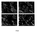
- the produced electrode substrate is called AS-1( Figure 8 ), which properties are shown in Table 3.
- Step 4 Use screen printing/spin coating/sputter coating equipments and processes to coat about 10 ⁇ m electrolyte (8YSZ material) layer onto the anode substrate AS-1 and place it in a high-temperature furnace at 1700°C for sintering at 1400°C/4hrs, with increasing and decreasing rates of temperature 1°C/min.
- the SOFC-MEA half cell from the process is called AS-H.
- Step 5 Use screen-printing equipment and process to coat about 40 ⁇ m LSM layer onto the 8YSZ electrolyet layer of the AS-H half cell to produce a full cell, called AS-WC.
- AS-C-I complete anode supported cell
Landscapes
- Chemical & Material Sciences (AREA)
- Engineering & Computer Science (AREA)
- Manufacturing & Machinery (AREA)
- Chemical Kinetics & Catalysis (AREA)
- Electrochemistry (AREA)
- General Chemical & Material Sciences (AREA)
- Physics & Mathematics (AREA)
- Thermal Sciences (AREA)
- Materials Engineering (AREA)
- Life Sciences & Earth Sciences (AREA)
- Sustainable Development (AREA)
- Sustainable Energy (AREA)
- Fuel Cell (AREA)
- Inert Electrodes (AREA)
Abstract

Description
- The invention is related to an innovative process for membrane electrode assembly, from formulating with raw materials, and preparing electrodes of planar SOFC-MEA containing anode and electrolyte substrate slurry, to making green tape of electrode by tape casting process. The green tape is cast into green substrate by lamination process, and then finished into high integrity green substrate by vacuum hot press system (VHPS). Through calcinations and sintering, the green substrate can be made into electrode substrate with high mechanical strength, controllable micro-structural characteristics (porosity/ gas permeability), thickness, and dimensions. Further, screen-printing, sputtering coating, spin coating, and spraying processes are alternatively employed to enable the production of high-performance SOFC unit cell. Their application to SOFC assures high reliability, durability and low degradation rate of the unit cell. The raw materials the invention refers to are YSZ/GDC/YDC/LSGM electrolytes, NiO + YSZ/GDC + NiO/YDC + NiO/LSGM + NiO anode materials and LSM/LSCF cathode materials. But they are not limited to the above materials.
- SOFC has high conversion efficiency, low noise, low pollution, high reliability and fuel diversity, as well as the potential to replace internal combustion engine in solving energy shortage issue. Especially when fossil fuels are in short supply, and hydrogen, natural gas and LPG become the alternatives, SOFC is a very important energy conversion device and plays a key role in the new energy era.
- The critical goals for the Planar Type Solid Oxide Fuel Cell-Membrane Electrode Assembly (SOFC-MEA) currently under development include high performance, high durability, high stability and low degradation rate of MEA. To achieve the above goals, the key factors are the MEA materials and structure design. Changing the materials and MEA structure also changes MEA properties. For materials, the electrolyte is mainly 8YSZ, which operation temperature depends on the supported substrate structure. Electrolyte Supported Cell (ESC) is operated at temperature range of 800 ∼ 1000°C with electrolyte thickness of 150∼300 µm and termed as first generation SOFC. The second generation SOFC adopts Anode Supported Cell (ASC), with operation temperature range of 650∼850 °C and electrolyte thickness of 10 µm. NiO+8YSZ are the anode materials for ASC/ESC with thicknesses of 50∼60 µm (ESC) and 500∼1200 µm (ASC). The cathode materials are mainly LSM and LSCF having thickness 30∼ 60 µm. New electrolyte materials and cathode materials are actively under development in many international laboratories. It is expected the new materials lower SOFC-MEA operation temperature to 500∼700°C. Then, the modules and parts for SOFC Stack, like inter-connector, can use metal materials to replace ceramic materials. The advantages will include easy fabrication, increased mechanical strength/stability/durability and reduced cost. Increasing SOFC marketing competitiveness and penetration will create huge niche for SOFC industry. The technical development in universities and national laboratories emphasizes materials development in the hope to lower resistance, increase ionic conductivity/ electric conductivity, and increase SOFC powder density. On Nature magazine, there are many publications on new electrolytes like LSGM, YDC, LSGMC and 10ScCeSZ, or new cathode materials like LSM/LSCF/LSF/LSC/LSCMBSCF/SSC. In industry, the emphasis is on material processing technology and performance stability. If the right materials are selected to achieve the desired properties and high reliability, and work with SOFC-MEA process and structure design, MEA mechanical/chemical stability, durability, energy conversion and powder output will be upgraded. Then, SOFC will become the best device in energy conversion.
- Many foreign laboratories have been through 15∼20 years investing in R&D and testing SOFC performance, also overcoming technical barriers and creating business opportunities. There is collaboration between corporation and national laboratory and joint venture is formed. Resource exchange, integration, merger or cooperation are taking place in Europe and America, such as ECN and InDEC, or H.C. Stark, IKTS and Karafol/Straxera/Webasto, NETL/SECA, EPFL and HT Ceramix. In the US, their national laboratories such as PNNL et al. and six large companies including Simens Westinghouse and GE and Delphi et al. are collaborating on verification of technical reliability, cost analysis and reduction to establish SOFC industry.
- The SOFC-MEA related materials that have potential for commercialization include those mentioned previously, such as 8YSZ as electrolyte, NiO+8YSZ as anode materials, LSM/LSCF and LSF/LSC as cathode materials. As for MEA processes, they are rarely published and proprietary to the companies who develop and do not want to patent the technologies because they are afraid their interest be hurt when the patented technologies are copied or modified by others.
- Current SOFC-MEA processes are based on tape casting to produce green tape of electrode first. The following lamination process allows adjustment for the thickness and geometry for green substrate. Then, the calcinations and sintering process produces electrode substrate or half cell substrate (including electrolyte layer and support electrode layer). At last, the screen-printing technique is used to build cathode layer onto half cell board, which completes the production of SOFC-MEA. The main drawbacks for the SOFC-MEA produced in this way are: insufficient mechanical strength, poor stability and durability (poor resistance to Redox Cycling/Thermal Cycling). Under the basic requirement for porosity (beneficial for gas-solid reaction mechanism) in cathode and anode, it is necessary to sacrifice mechanical strength. Later, this will cause rupture and failure to the assembled cell stack. Such a drawback hinders the development of perfect structure for SOFC and prompts immediate slurry.
- The main objective for the invention is to provide a material recipe and its process to produce HI-SOFC-MEA or HI-Unit Cell. Such a HI-SOFC-MEA has ① high mechanical strength and hardness ② adjustable substrate porosity and gas permeability③ controllable MEA multi-layer materials and microstructure or density ④ controllable MEA layer number and
thickness ⑤ high sintering density ⑥ high stability and robust operational capability. Due to the above special characteristics, the HI-SOFC-MEA can increase cell output powder density and fuel energy conversion efficiency. The most important feature is its high mechanical strength that is suitable for Cell Stack assembly and test. Cells with fragility tend to cause rupture or lower reliability and yield for cell stacks during production or testing process. - The content for the invention contains one recipe and two (electrode green substrate and electrode substrate) processes. They are described as follows respectively:
- Recipe and process for producing electrode green substrate:
- The typical recipe for the electrode substrate slurry is listed in Table 1.


- Primary materials include a. electrode materials, 8YSZ as electrode materials and NiO+8YSZ as anode materials; b. organic additives, MEK and EtOH as organic solvents, TEA as dispersant, DBP and PEG as plasticizers, PVB as binder; c. graphite as pore former.
- The weight percentages for materials in the recipes are also listed in Table 1. The compound formulas or ingredients are listed in Table 2.
Table 2: Major Compound Formulas or Ingredients Material Short Name Chemical Formula (Representative Ingredient) Note YSZ (Y2O3)0.08(ZrO2)0.92 MEK CH3COC2H5 EtOH C2H5OH TEA C6H15NO3 DBP C16H22O4 PEG OH(C2H4O)n H PVB Polyvinyl Butyral Chemical formula (NA) GDC Gd0.2Ce0.801.9 YDC Y0.08Ce0.9203±δ LSGM La0.8Sr0.2Ga0.85Mg0.15O3±δ LSM La0.8Sr0.2MnO3 LSCF La0.6Sr0.4CO0.2Fe0.803±δ LSC Lanthanum Strontium Cobaltite Chemical formula (NA) LSF Lanthanum Strontium Ferrite Chemical formula (NA) LSCM La0.8Sr0.2Co0.85Mg0.15O3±δ - For electrolyte substrate/layer recipe, its optimum composition in weight percentage is: 8YSZ (68wt%), MEK (17wt%), EtOH (7wt%), TEA (1.5wt%), DBP (1.0wt%), PEG (1.0wt%), PVB (4.5wt%) and pore former (0.wt%). Since the electrolyte layer requires "zero gas permeability and 100% tightness", there is no need of pore former. For anode substrate/ layer recipe, the optimum composition is: NiO + 8YSZ (68wt%) (NiO/8YSZ has weight ratio 50/50 (approximately optimum value)), MEK (17wt%), EtOH (7wt%), TEA (1.5wt%), DBP (1.0wt%), PEG (1.0wt%), PVB (4.5wt%), pore former (graphite) (0.1∼10 wt% of anode material). The amount of pore formers can be adjusted according to the porosity required by anode substrate. The weight percentage in Table 1 can be adjusted according to the powder characteristics of the electrode materials (pore diameter distribution and specific surface area et al.). The goal is to produce high uniformity and high quality green products with suitable operation parameters for tape casting (such as thickness/density/operational feasibility). The electrode materials and pore formers in the recipe need pretreatment. The primary process is to grind the electrode powder materials down to 200-300 nm by a ball mill (containing zirconium dioxide). Then, the powder materials, organic solvents and dispersants are ground together inside the ball mill for about 24-48 hours (adjustable to reduce grinding time) to attain uniformity. At last, plasticizers and binders are added to the ball mill for grinding for another 24-48 hours (adjustable to reduce grinding time) to attain complete uniformity and slurry. To attain the required green thickness, it is necessary to do fine adjustment of recipe and carryout viscosity measurement and adjustment. If the green thickness is 10∼200 µm, the slurry viscosity is 100∼1500 cp (depending on the original powder characteristics; experience and techniques are essential to process optimization), so the optimal viscosity will facilitate tape casting operation.
- Tape casting process can achieve good quality green tape with good techniques and compliance to operation procedures for any specific equipment model.
- The green tape produced from previous (1) process is made into a single layer green product in certain size by punching/blanking. Then a number of green products are selected to go through inspection, stacking and Lamination Process (LP) to produce electrode green substrate-A with definite thickness and shape. The lamination process has temperature at 60∼100°C and pressure at 2000 psi - 5000 psi. At this time, the green substrate -A density is 40% of the theoretical density for the same ceramic oxides as the electrode materials. The green substrate -A will go to the second stage VHPS to produce green substrate-B. The process vacuum is 10-3∼10-4 torrs and pressure is 1.68 × 10⁵ psi (area = 9 cm2) ∼1.52 × 10⁴ psi (area = 100cm2), and temperature is 500°C. The density for this green substrate-B can reach 70% of the theoretical density for the same ceramic oxides as the electrode materials. Such two-stage vacuum heat lamination process is defined as Novel Synergistic Process (NSP). During LP stage, the green is placed freely on the pressboard. While during VHPS stage, the green is sealed and placed in the mold with definite size. The electrode green substrate through NSP process has high integrity. After calcinations/sintering, the electrode ceramic substrate has high integrity and extremely high mechanical strength. Further through other treatments or processes for other electrode layers (like cathode or electrolyte), such as screen-printing, sputtering coating, plasma coating/spraying, spin coating et al., the unit cell is produced with unique properties, including high mechanical strength (suitable for cell stack assembly and testing), high durability and stability. This is called "high integrity fuel cell membrane electrode assembly". By changing the amount of pore former, it is possible to adjust the content and microstructure for the anode substrate to vary the porosity between different layers, to increase gas permeability rate, to increase cell energy conversion efficiency and output powder density. Thus, the key technology to produce SOFC-MEA is developed to improve the product specification requirements and performance.
-
-
Figure 1 is a novel synergistic process for fabrication of a high integrity membrane electrode assembly of solid oxide fuel cell. -
Figure 2 is a brief illustration for the vacuum hot press system (VHPS) in the invention. -
Figure 3 is the structure diagram and actual object diagram for the planar SOFC Anode Supported Cell (ASC) in the invention. -
Figure 4 is the slurry recipe and process for the fabrication of SOFC-MEA electrode substrate in the invention. -
Figure 5 is the diagram of the slurry for the fabrication of high-integrity electrode green substrate in the invention. -
Figure 6 is the diagram of the actual object of green tape of the high-integrity electrode substrate in the invention. -
Figure 7 is the diagram of the actual object of the high-integrity green substrate of the electrode substrate in the invention. -
Figure 8 is the diagram of the actual object of the high-integrity electrode substrate. -
Figure 9 is the microstructure and property diagram for the high-integrity electrode substrate. -
Figure 10 is the diagram of the actual object and the electric performance testing results for the SOFC-MEA (unit cell) produced from the high-integrity electrode substrate. - The invention is related to the recipe and novel processes for producing SOFC-MEA (refer to
Figure 1 for the brief processes), a high integrity solid oxide fuel cell - membrane electrode assembly or unit cell. The main content in the invention includes "one recipe and two processes for producing green substrates and electrode ceramic substrate. The application methods are described below: -
- Step 1: Add self-made or purchased 8YSZ and NiO powders in a certain weight ratio (NiO is 35-65 wt% of NiO+8YSZ; its QOV value is 50 wt%) and zirconium dioxide grinding balls into a jar for 24-168 (adjustable) hours of grinding to attain highly uniform powder mixture. Its uniformity can be judged by SEM analysis. If necessary, additional grinding time and speed are used. The average particle diameter is targeted at 300∼500 nm (adjustable based on requirements). The powder is named Anode-P-1. Powder properties include particle diameter, specific area, and uniformity (EDX-Mapping), which are filed as references and review. This is the first work to prepare slurry for electrode green substrate. The main recipe is listed in Table 1. It is the first part of IP for the invention.
- Step 2: The powder Anode-P-1 is taken out and placed in the zirconium dioxide plate which is then put in high-temperature furnace for co-sintering treatment at 1200∼1600°C for 2∼8 hours (adjustable). Then, it is subject to grinding by ball mill as in step 1, so this makes particle diameter around 300-500 nm (adjustable if necessary) and high uniformity. This kind of powder is called Anode-P-2. To adjust the porosity for the final substrate, a proper amount of pore former (graphite is a typical material) is added to Anode-P-2. Then it is subject to repeated grinding for a few hours (preferably over 24 hours) and becomes the powder called Anode-P-3.
- Step 3: Take a certain amount of Anode-P-3 to dry at 100°C for several tens of hours (preferably over 24 hours, to remove moisture and water). According to the recipe in Table 1, take organic solvents MEK, EtOH in a certain ratio and dispersant TEA to add to grinding jar with zirconium dioxide ball for grinding for several tens of hours (preferably over 24 hours) to assure the system uniformity. This uniform slurry of solvent and dispersant is called SD.
- Step 4: Add dried powder Anode-P-3 into SD slurry to grind in liquid state for several tens of hours (preferably over 48 hours), so this makes even mixing of powder, solvent and dispersant and produces the slurry called SL-1.
- Step 5: according to Table 1 recipe, take a certain amount of plasticizer PEG and binder PVB to add into slurry SL-1. Continue the grinding for several tens of hours (about 48∼72 hours) to assure complete system uniformity and the quality for anode substrate slurry that is suitable for tape casting process, called SL-2.Use viscometer to measure and note the viscosity for SL-2 and check it characteristics.
- Step 6: Use micro-adjustment technique to add a proper amount of binder in different stage, while plasticizer can regulate SL-2 viscosity 150∼1500 CP (QOV=200∼500 CP). The recipe effect for this part depends on personal experience, technology and capability to determine the number and duration for trial and error operation. The final tape casting slurry is called SL-T°
- Step 7: Process slurry SL-T with tape casting system to produce green tape, which width depends on the requirement, generally around 18 ∼ 30 cm. The single layer thickness is around 10 ∼ 300 µm (whether to increase single layer thickness depending on the requirement and tape casting system performance).
- Step 8: Use cutting tools or punch to cut green tape into single layer green tape in certain size and shape (usually square or circle). According to thickness requirement, send the stack of single layer green tapes into laminator (LM) to produce shaped green substrate (GT-1). The laminator (LP) pressure is set to 2000-5000 psi, and temperature is 50∼100 °C . GT-1 thickness can be 100∼1500 µm. Substrate thickness QOV = 600∼1200µm. GT1green density is measured by Pychrometer.
-
- Step 1: Put green substrate (GT-1)(
dimension 5×5cm2∼ 15×15cm2(or larger), thickness close to 600∼1200 µm) in a mold of 5×5 cm2 or suitable size. Send it to "vacuum hot press system (VHPS)(details as inFigure 2 ) for vacuum (less than 1×10⁻³ torrs) heat (temperature <500°C) pressure (up to 1.68×10⁵ psi, adjustable) treatment. The high-density green substrate (GT-2) after this process has green density measured by Pychrometer and up to 70% of the theoretical density for the same ceramic oxides. - Step 2: If necessary, surface treatment for GT-2 can be done by LM lamination. Such substrate enhancing process by LM and VHPS is called A Novel Synergistic Process. The substrate made from the process is called GT-F.
- Step 3: Press and position GT-F with zirconium dioxide substrate (in sandwich structure). Place it in a high temperature furnace with aluminum oxide/Zirconium oxide setters as support (temperature up to 1700°C) for two-stage cyclic sintering process. The first cycle temperature control is: room temperature → 200°C(4Hr) → 450°C (2Hr) → 750°C (2Hr) → 1250°C (6Hr) → room temperature. And the second cycle temperature control is: room temperature → 1400°C (4Hr) → room temperature. The increasing and decreasing rates for temperature are the same for the two stages and kept at 1°C/min (preferably within 3°C/min). A certain amount of air is passed in. The first cycle sintering is to remove all organic additives. The second cycle sintering is to produce ceramic substrate by sintering and densification. The produced electrode substrate is called AS-1, which needs to be characterized for sintering density, mechanical strength, and porosity and microstructure et al. Such AS-1 electrode substrate has high mechanical strength, flatness, suitable porosity and gas permeability to satisfy the basic requirements of SOFC-MEA electrode structure.
- Step 4: AS-1 is subject to Screen Printing, Sputtering Coating, Spin Coating or Plasma Spray. Then it is subject to coating with an electrode layer in less than 10 µm. It is put in high temperature sintering furnace (1400°C/4Hr) with the increasing and decreasing rates for temperature at 1°C/min to produce SOFC-MEA half cell, called AS-H.
- Step 5: AS-H half cell is subject to screen-printing for coating LSM (or LSCF material) cathode layer in 30-50 µm (adjustable) onto YSZ layer. Then it is put in a high-temperature sintering furnace (1200°C/3∼4Hr) with the increasing and decreasing rates for temperature at 1°C/min (preferably less than 3°C/min). The product is called ASC-I, which is anode support cell (also called ASC type SOFC-MEA)(details as shown in
Figure 3 for multiple/functional layer anode substrate (NiO+YSZ)). - The ASC type SOFC from the above processes can convert a variety of fuels like hydrogen, natural gas and hydrocarbons into electric output. The following will describe some examples in details for the invention:
- The example is about production of a planar SOFC anode substrate with high mechanical strength and suitable porosity (20∼30vol %) and its unit cell for powder supply test and powder generation. The production includes two stages. The first stage is about (1) NiO+ YSZ anode green substrate slurry recipe and processes, including 8 steps in total, and (2) anode ceramic substrate production process, 5 steps in total, which are described respectively in the following:
-
- Step 1: Mix 175 grams of 8YSZ with cubic crystal structure and equal amount of NiO (
average particle diameter 1000 nm) and place them in a jar containing ZrO2 grinding balls (about 250 grams) for 168 hours of grinding. This allows complete mixing of NiO and 8YSZ to become highly uniform powder mixture. SEM can analyze its uniformity. If necessary, additional grinding time and speed can be used. The goal of grinding is to getparticle diameter 300∼500 nm. The powder is called Anode-P-1. Powder properties include particle diameter, specific surface area, and uniformity (EDX-Mapping), which are filed as references and review. - Step 2: Take powder Anode-P-1 out of a grinding jar and place it in a zirconium dioxide plate which will be put in a high-temperature sintering furnace at 1400°C /4 hours for co-sintering. After that, repeat step 1 grinding process to make
particle diameter 300∼500 nm and uniform. This co-sintered powder is called Anode-P-2. Add 3.5 grams of sub-micrometer/ nanometer graphite powder into Anode-P-2 and repeat grinding for over 24 hours to assure high uniformity. The powder is called Anode-P-3. It total weight is 353.5 grams. - Step 3: Take 353.5 grams of Anode-P-3 and dry it at 100°C for over 24 hours to remove water and moisture. Weigh 78.1 grams of MEK, 25.27 grams of EtOH and 8.05 grams of TEA into a grinding jar containing ZrO2 Ball for grinding for over 24 hours to assure uniformity. The solvents and dispersant are liquid and the mixture is called SD solution, which total weight is 111.42 grams.
- Step 4: Add dried Anode-P-3 powder into SD solution and grind in liquid state for over 48 hours. This allows powder, solvents and dispersant to mix uniformly into slurry, called SL-1, which total weight is 464.92 grams.
- Step 5: Weigh 4.59 grams of DBP plasticizer, 4.59 grams of PEG and 19.55 grams of PVB binder into slurry SL-1. Continue grinding in liquid state for over 48 hours to assure system uniformity. The product is the anode substrate slurry suitable for tape casting process and called SL-2 which total weight is 463.65 grams. Then, viscometer is used to measure and note the viscosity of SL-2 and inspect SL-2 properties.
- Step 6: To make fine adjustment, suitable amount of PVB binder is added in different stages with plasticizer DBP/PEG to regulate the viscosity of SL-2 around 150∼1500 cp (optimum viscosity around 200∼500 cp). At the same time, inspect formability for the green tape. This adjustment depends on personal experience and technique/capability for the time and number of trial and error. The final tape slurry or slip slurry is called SL-T. Its viscosity is about 328 cp (as shown in
Figure 5 ). - Step 7: Process tape slurry SL-7 with tape casting system to produce green tape, which width depends on the suitability for specific tape casting system, between 18 and 20 cm. The single layer thickness is about 100 µm. The length is determined by the amount of Anode-P- I feeding powder (as shown in
Figure 6 ). - Step 8: Use cutting tools or punch to cut green tape into single layer green tape in 5×5cm2 or 10×10cm2 (adjustable in size and shape) with
thickness 100 µm. Send the stack of 12 single layer green tapes into high-pressure laminator (LM) to produce shaped (square) green substrate (GT-1) withthickness 1200 µm. The pressure for the laminator in this step is set at 2000∼5000 psi, temperature at 50∼100°C. The green density for GT1 is measured by Pychrometer (details as shown inFigure 7 ). - Step 1: Place green substrates GT1 (square with
dimensions 5×5 cm2 and 10×10 cm2, thickness 1200 µm) into a 5×5cm2 mold and a 10×10cm2 mold respectively (mold material is stainless steel, plated with WC). Then send them to vacuum hot press system (VHPS) for further treatment (vacuum less than 1×10⁻³torrs, temperature < 500°C). Its pressure is up to 1.68×10⁵ psi (adjustable). The high-density green substrate from the process (called GT-2) has green density measured by Pychrometer, and up to 70% of the theoretical density of the same ceramic oxides.
Step 2: If necessary, further surface finishing for GT-2 can be done through LM lamination. Such process using LM and VHPS to enhance green substrate strength is called "a novel synergistic process". The finished product from the process is called GT-F. The size of GT-F is determined by the product requirement and the VHPS mold size.
Step 3: Use zirconium dioxide substrates to press GT-F (in sandwich structure) and place it in a zirconium dioxide support plate in a high-temperature furnace (temperature up to 1700 °C) for a two-stage cyclic sintering process. The first cycle temperature control is room temperature → 200°C (4Hrs) → 450°C (2 hrs) → 750°C (2 hrs) → 1250°C (6 hrs) → room temperature. The second cycle temperature control is room temperature → 1400°C (4 hrs) → room temperature. The increasing and decreasing rates for temperature for the two stages are kept at 1°C/min (preferably within 3°C/min). A certain amount of air is also supplied to the system. The produced electrode substrate is called AS-1(Figure 8 ), which properties are shown in Table 3.Table 3: Properties of Anode Substrate Property Description 1. size L×W×H (Thickness) =
50mm×50mm×1000µm &
100mm×100mm×1000µm2. shape Planar/ high flatness 3. mechanical strength a. 67.1 Mpa (T=25°C)
82.91Mpa (T=700°C)
76.17Mpa high flatness (T=800°C)4. porosity (T=25°C) a. initial value =14.534 %
b. value after H2 reduction =26.1187 %5. air/gas permeability (T=25°C), initial value 1.14 x 10⁻⁴ 1/psi-cm2-sec Figure 9 ).
Step 4: Use screen printing/spin coating/sputter coating equipments and processes to coat about 10 µm electrolyte (8YSZ material) layer onto the anode substrate AS-1 and place it in a high-temperature furnace at 1700°C for sintering at 1400°C/4hrs, with increasing and decreasing rates of temperature 1°C/min. The SOFC-MEA half cell from the process is called AS-H.
Step 5: Use screen-printing equipment and process to coat about 40 µm LSM layer onto the 8YSZ electrolyet layer of the AS-H half cell to produce a full cell, called AS-WC. Place AS-WC in the high-temperature furnace for another sintering process (1200°C/3hrs) with increasing and decreasing rates of temperature at 1°C/min. The produced SOFC-MEA is called AS-C-I (details inFigure 10 ), which a complete anode supported cell (also called ASC type SOFC-MEA). On ASC-I, the electric powder density measured by a simple Probostat System can be up to 32 mW/cm2 (test area = πcm2, temperature = 900°C). If the test area is 4x4cm2, the electric powder density is larger than 350 mW/cm2 (temperature at 800°C) (prototype MEA not optimized product).
Claims (15)
- A method for fabrication of membrane electrode assembly of solid oxide fuel cell (MEA-SOFC) including: 1) slurry recipe and process for producing electrode green substrate and 2) fabrication process for electrolyte or electrode ceramic substrate, comprising steps:1) Slurry recipe and process for producing electrode green substrate:(a) Use recipe for the electrode substrate slurry as listed in Table 1, prepare relevant material powder, organic additives and dispersant;(b) Add relevant powder material 8YSZ and NiO in a ratio listed in Table 1 (NiO+8YSZ for anode substrate, and 8YSZ for electrolyte substrate) in a jar containing zirconium dioxide grinding balls for grinding to attain initial uniformity and particle diameter standardization of all powder materials, and examine the powder characteristics to fulfill specification;(c) Place the powder from step b in high-temperature furnace for co-sintering treatment to attain solid uniformity, and then take out the powder to proceed to second time grinding with zirconium dioxide grinding balls at room temperature, and a proper amount of pore former is added to attain a second time uniformity of all powder materials, and then dry to remove moisture and water, the power is designated powder c;(d) According to the recipe in Table 1, take organic solvents MEK, EtOH in a certain ratio and dispersant TEA to add in the product of step c for grinding with zirconium dioxide ball to assure uniformity, the uniform liquid state of the solvent and dispersant in this step is called SD;(e) Add the product of step d (SD) to the powder of step c, for the third time grinding with zirconium dioxide ball to make even mixing of powder and solvent/dispersant, and dissolve/disperse into slurry designated slurry e ;(f) According to the recipe in Table 1, take a certain amount of plasticizer DBP, PEG and binder PVB to add into slurry e, proceed the fourth time grinding with zirconium dioxide ball to assure the uniformity as a whole to attain the product of step f, designated substrate f ( electrolyte or electrode slurry), measure and record its viscosity with viscosity meter;(g) Use micro-adjustment technique to add a proper amount of binder and plasticizer to regulate viscosity of substrate f slurry for suitable tape casting operation, the preferable substrate slurry is designated tape slurry g;(h) Process tape slurry g with a tape casting system to produce green tape, which thickness and width maybe adjusted based on the requirement;(i) Use cutting tools or punch to cut green tape into single layer green tape in certain size and shape, which are laminated and aligned in stack according to thickness requirement, and deliver into laminator (LM) for synergistic operation to produce shaped green substrate (GS, electrolyte or electrode type), record the characteristics for further adjustments;2) Fabrication process for electrolyte or electrode ceramic substrate(j) Put green substrate produced in step (i) in a metal mold of same size, deliver it to vacuum hot press system (VHPS) for vacuum (less than 1×10⁻³ torrs) heat (temperature < 500 °C) pressure (up to 1.68×10⁵ psi, adjustable) treatment to produce high-density green substrate (HDGS), and measure and record the density;(k) If necessary, surface treatment for HDGS can be done by LM lamination, such substrate enhancing process by LM and VHPS alternately is called a novel synergistic process, the substrate made from the process is called high integrity green substrate (HIGS);(l) Press and position HIGS with zirconium dioxide ceramic substrate (in sandwich structure) under constant temperature, place it in a high temperature furnace with aluminum oxide /Zirconium oxide setters as support (temperature up to 1700°C) for two-stage cyclic sintering process, the first cycle is to remove all organic additives and pore former, the second cycle sintering is to enhance density of ceramic substrate by sintering, the produced electrode substrate is called high integrity ceramic substrate (HICS);(m) HICS is subject to screen printing, sputtering coating, spin coating or plasma spray for coating with an electrode layer (if HICS is electrolyte ceramic substrate) or electrolyte layer (if HICS is anode ceramic substrate) with proper thickness, and put it in high temperature sintering furnace to produce SOFC-MEA half cell (HC);(n) HC half cell is subject to screen-printing/sputtering coating/spin coating/plasma spray or slurry spray for coating LSM (or LSCF material) cathode layer, and put in a high-temperature furnace for sintering to produce SOFC-MEA unit cell.
- A method for fabrication of membrane electrode assembly of solid oxide fuel cell (MEA-SOFC) of claim 1, wherein step (a) of slurry recipe and process for producing electrode green substrate is in accordance with the slurry recipe and process for producing electrode/electrolyte green substrate as listed in Table 1, in which QOV includes the value indicated, but not limited to, and the weight ratio of NiO in NiO+8YSZ includes 35-65 wt%, but not limited to.
- A method for fabrication of membrane electrode assembly of solid oxide fuel cell (MEA-SOFC) of claim 1, wherein first grinding time in step (b) of slurry recipe and process for producing electrode green substrate includes 24∼168 hours, but not limited to, and the targeted average particle diameter of ground powder includes 300∼500nm, but not limited to.
- A method for fabrication of membrane electrode assembly of solid oxide fuel cell (MEA-SOFC) of claim 1, wherein the high temperature for co-sintering in step (c) of slurry recipe and process for producing electrode green substrate includes 1200∼1600°C, but not limited to, and the second grinding time and targeted average particle diameter include 24 hours above and 300-500 nm, respectively, but not limited to, and the added pore formers include graphite powder of nanometer or micrometer size, but not limited to, depending on the porosity required by the substrate to be formed.
- A method for fabrication of membrane electrode assembly of solid oxide fuel cell (MEA-SOFC) of claim 1, wherein the ball grinding time in step (d) of slurry recipe and process for producing electrode green substrate includes 24 hours above, but not limited to.
- A method for fabrication of membrane electrode assembly of solid oxide fuel cell (MEA-SOFC) of claim 1, wherein third ball grinding time in step (e) of slurry recipe and process for producing electrode green substrate includes 48 hours above, but not limited to.
- A method for fabrication of membrane electrode assembly of solid oxide fuel cell (MEA-SOFC) of claim 1, wherein fourth ball grinding time in step (f) of slurry recipe and process for producing electrode green substrate includes 48-72 hours, but not limited to.
- A method for fabrication of membrane electrode assembly of solid oxide fuel cell (MEA-SOFC) of claim 1, wherein the substrate slurry viscosity in step (g) of slurry recipe and process for producing electrode green substrate includes between 150∼1500CP, but not limited to.
- A method for fabrication of membrane electrode assembly of solid oxide fuel cell (MEA-SOFC) of claim 1, wherein the specification of the green tape in step (h) of slurry recipe and process for producing electrode green substrate includes width of 18∼30 cm and thickness of 10∼300 µm, but not limited to.
- A method for fabrication of membrane electrode assembly of solid oxide fuel cell (MEA-SOFC) of claim 1, wherein the shape of green tape in step (i) of slurry recipe and process for producing electrode green substrate includes round or square, but not limited to, the size of green tape includes 5×5cm2∼15×15 cm2, but not limited to, the operation temperature and pressure of laminator includes 50∼100°C and 2000-5000 psi, respectively, but not limited to, and the thickness of green tape formed includes 600∼1200 µm, but not limited to.
- A method for fabrication of membrane electrode assembly of solid oxide fuel cell (MEA-SOFC) of claim 1, wherein the operation temperature and pressure of vacuum hot press sintering system in step (j) of the fabrication process for electrode or electrolyte ceramic substrate includes < 500°C and 1.68×10⁵ psi, respectively, but not limited to, and the vacuum includes 1.0×10⁻³ torrs, but not limited to, or at room temperature with specific pressure.
- A method for fabrication of membrane electrode assembly of solid oxide fuel cell (MEA-SOFC) of claim 1, wherein the lamination operation in step (k) of the fabrication process for electrode or electrolyte ceramic substrate includes second lamination, but not limited to.
- A method for fabrication of membrane electrode assembly of solid oxide fuel cell (MEA-SOFC) of claim 1, wherein first cycle sintering process in step (1) of the fabrication process for electrode or electrolyte ceramic substrate includes temperature control: room temperature →200°C (4 hrs) →450°C (2hrs) →750°C (2hrs) →1250°C (6hrs) →room temperature, but not limited to, and second cycle sintering process includes temperature control: room temperature →1400°C (4hrs) → room temperature, the temperature increment/decrement control rate of the two cycle sintering process includes 1°C/min, but not limited to, preferably below 3°C/min.
- A method for fabrication of membrane electrode assembly of solid oxide fuel cell (MEA-SOFC) of claim 1, wherein the thickness of electrolyte layer in step (m) of the fabrication process for electrode or electrolyte ceramic substrate includes 10 µm, but not limited to, the product sintering process includes temperature control: room temperature →1400°C (4hrs) → room temperature, the temperature increment/decrement control rate of the sintering process includes 1°C/min, but not limited to, preferably below 3°C/min.
- A method for fabrication of membrane electrode assembly of solid oxide fuel cell (MEA-SOFC) of claim 1, wherein the material and thickness of cathode layer in step (n) of the fabrication process for electrode or electrolyte ceramic substrate includes LSM/LSCF and 30∼50 µm, respectively, but not limited to, the product sintering process includes temperature control: room temperature →1200°C (3hrs) →room temperature, the temperature increment/decrement control rate of the sintering process includes 1°C/min, but not limited to, preferably below 3°C/min.
Priority Applications (2)
| Application Number | Priority Date | Filing Date | Title |
|---|---|---|---|
| DE602007005808T DE602007005808D1 (en) | 2007-09-24 | 2007-09-24 | A new synergistic process and formulation for producing a high integrity membrane electrode assembly for a solid oxide fuel cell |
| EP07018745A EP2045858B1 (en) | 2007-09-24 | 2007-09-24 | A novel synergistic process and recipe for fabrication of a high integrity membrane electrode assembly of solid oxide fuel cell |
Applications Claiming Priority (1)
| Application Number | Priority Date | Filing Date | Title |
|---|---|---|---|
| EP07018745A EP2045858B1 (en) | 2007-09-24 | 2007-09-24 | A novel synergistic process and recipe for fabrication of a high integrity membrane electrode assembly of solid oxide fuel cell |
Publications (2)
| Publication Number | Publication Date |
|---|---|
| EP2045858A1 true EP2045858A1 (en) | 2009-04-08 |
| EP2045858B1 EP2045858B1 (en) | 2010-04-07 |
Family
ID=38988424
Family Applications (1)
| Application Number | Title | Priority Date | Filing Date |
|---|---|---|---|
| EP07018745A Active EP2045858B1 (en) | 2007-09-24 | 2007-09-24 | A novel synergistic process and recipe for fabrication of a high integrity membrane electrode assembly of solid oxide fuel cell |
Country Status (2)
| Country | Link |
|---|---|
| EP (1) | EP2045858B1 (en) |
| DE (1) | DE602007005808D1 (en) |
Cited By (4)
| Publication number | Priority date | Publication date | Assignee | Title |
|---|---|---|---|---|
| CN102167586A (en) * | 2011-01-20 | 2011-08-31 | 中南大学 | Low-temperature activated sintered 8YSZ-based ceramic and preparation method thereof |
| CN103074565A (en) * | 2012-12-11 | 2013-05-01 | 北矿新材科技有限公司 | Preparation method of solid oxide electrolytic cell connector coating spraying powder |
| WO2015059166A1 (en) * | 2013-10-22 | 2015-04-30 | Danmarks Tekniske Universitet | Planar half-cell shaped precursor body |
| CN114335641A (en) * | 2022-01-06 | 2022-04-12 | 苏州华清京昆新能源科技有限公司 | Low-temperature sintering electrolyte compact preparation method |
Citations (6)
| Publication number | Priority date | Publication date | Assignee | Title |
|---|---|---|---|---|
| US4857420A (en) * | 1987-10-13 | 1989-08-15 | International Fuel Cell Corporation | Method of making monolithic solid oxide fuel cell stack |
| US5273837A (en) * | 1992-12-23 | 1993-12-28 | Corning Incorporated | Solid electrolyte fuel cells |
| DE4307967A1 (en) * | 1993-03-12 | 1994-09-15 | Siemens Ag | Integrated ceramic high-temperature fuel cell |
| US20040183055A1 (en) * | 2001-07-04 | 2004-09-23 | Thierry Chartier | Method of preparing a thin ceramic composition with two materials, the composition thus obtained and the constituent electrochemical cell and membrane |
| US20060269813A1 (en) * | 2005-05-31 | 2006-11-30 | Seabaugh Matthew M | Supported ceramic membranes and electrochemical cells and cell stacks including the same |
| US20070178366A1 (en) * | 2006-01-09 | 2007-08-02 | Saint-Gobain Ceramics & Plastics, Inc. | Fuel cell components having porous electrodes |
-
2007
- 2007-09-24 DE DE602007005808T patent/DE602007005808D1/en active Active
- 2007-09-24 EP EP07018745A patent/EP2045858B1/en active Active
Patent Citations (6)
| Publication number | Priority date | Publication date | Assignee | Title |
|---|---|---|---|---|
| US4857420A (en) * | 1987-10-13 | 1989-08-15 | International Fuel Cell Corporation | Method of making monolithic solid oxide fuel cell stack |
| US5273837A (en) * | 1992-12-23 | 1993-12-28 | Corning Incorporated | Solid electrolyte fuel cells |
| DE4307967A1 (en) * | 1993-03-12 | 1994-09-15 | Siemens Ag | Integrated ceramic high-temperature fuel cell |
| US20040183055A1 (en) * | 2001-07-04 | 2004-09-23 | Thierry Chartier | Method of preparing a thin ceramic composition with two materials, the composition thus obtained and the constituent electrochemical cell and membrane |
| US20060269813A1 (en) * | 2005-05-31 | 2006-11-30 | Seabaugh Matthew M | Supported ceramic membranes and electrochemical cells and cell stacks including the same |
| US20070178366A1 (en) * | 2006-01-09 | 2007-08-02 | Saint-Gobain Ceramics & Plastics, Inc. | Fuel cell components having porous electrodes |
Cited By (4)
| Publication number | Priority date | Publication date | Assignee | Title |
|---|---|---|---|---|
| CN102167586A (en) * | 2011-01-20 | 2011-08-31 | 中南大学 | Low-temperature activated sintered 8YSZ-based ceramic and preparation method thereof |
| CN103074565A (en) * | 2012-12-11 | 2013-05-01 | 北矿新材科技有限公司 | Preparation method of solid oxide electrolytic cell connector coating spraying powder |
| WO2015059166A1 (en) * | 2013-10-22 | 2015-04-30 | Danmarks Tekniske Universitet | Planar half-cell shaped precursor body |
| CN114335641A (en) * | 2022-01-06 | 2022-04-12 | 苏州华清京昆新能源科技有限公司 | Low-temperature sintering electrolyte compact preparation method |
Also Published As
| Publication number | Publication date |
|---|---|
| EP2045858B1 (en) | 2010-04-07 |
| DE602007005808D1 (en) | 2010-05-20 |
Similar Documents
| Publication | Publication Date | Title |
|---|---|---|
| US7914636B2 (en) | Synergistic process and recipe for fabrication of a high integrity membrane electrode assembly of solid oxide fuel cell | |
| JP5560381B1 (en) | Fuel cell | |
| CA2691025C (en) | Electrochemical device | |
| Shen et al. | Co-sintering anode and Y2O3 stabilized ZrO2 thin electrolyte film for solid oxide fuel cell fabricated by co-tape casting | |
| US8956781B2 (en) | Fuel cell including a cathode comprising a sub phase composed of tricobalt tetroxide | |
| CN113394439A (en) | Method of forming an electrolyte | |
| EP2045858B1 (en) | A novel synergistic process and recipe for fabrication of a high integrity membrane electrode assembly of solid oxide fuel cell | |
| CN111009675B (en) | Solid oxide fuel cell and preparation method thereof | |
| KR101307560B1 (en) | Fabrication and structure of low- and intermediate-temperature-operating solid oxide fuel cell by spin coating and low-temperature sintering | |
| JP5099892B2 (en) | Manufacturing method of membrane electrode assembly for highly consistent solid oxide fuel cell | |
| JP2007200664A (en) | Method of manufacturing solid oxide fuel cell | |
| JP5841210B1 (en) | Fuel cell | |
| JP2011142042A (en) | Power generation cell for solid oxide fuel battery and its manufacturing method | |
| JP6042320B2 (en) | Electrode materials and their use | |
| JP5805232B2 (en) | Solid oxide fuel cell | |
| JP5638687B1 (en) | Air electrode material | |
| WO2022192081A1 (en) | Substrate for a metal-supported electrochemical cell | |
| JP5395295B1 (en) | Fuel cell | |
| JP2009218126A (en) | Manufacturing method for completely-dense electrolyte layer laminated on high-performance solid oxide type fuel-cell membrane-electrode assembly (sofc-mea) | |
| Rieu et al. | Fabrication and Characterization of Anode‐Supported BaIn0. 3Ti0. 7O2. 85 Thin Electrolyte for Solid Oxide Fuel Cell | |
| Ding et al. | Methane-Fueled Proton-Conducting Ceramic Fuel Cell Stacks | |
| WO2011036972A1 (en) | Cell of solid oxide fuel cell | |
| WO2010135416A1 (en) | Ion conducting composite electrolyte for solid state electrochemical devices | |
| KR101327673B1 (en) | Granular powder for a sacrifice lubrication layer interposed between electrode and electrolyte of solid oxide fuel cell and the method for manufacturing solid oxide fuel cell using the same | |
| TW200908424A (en) | A novel synergistic process and recipe for fabrication of a high integrity membrane electrode assembly of solid oxide fuel cell |
Legal Events
| Date | Code | Title | Description |
|---|---|---|---|
| PUAI | Public reference made under article 153(3) epc to a published international application that has entered the european phase |
Free format text: ORIGINAL CODE: 0009012 |
|
| 17P | Request for examination filed |
Effective date: 20081110 |
|
| AK | Designated contracting states |
Kind code of ref document: A1 Designated state(s): AT BE BG CH CY CZ DE DK EE ES FI FR GB GR HU IE IS IT LI LT LU LV MC MT NL PL PT RO SE SI SK TR |
|
| AX | Request for extension of the european patent |
Extension state: AL BA HR MK RS |
|
| GRAP | Despatch of communication of intention to grant a patent |
Free format text: ORIGINAL CODE: EPIDOSNIGR1 |
|
| AKX | Designation fees paid |
Designated state(s): DE FR NL |
|
| GRAS | Grant fee paid |
Free format text: ORIGINAL CODE: EPIDOSNIGR3 |
|
| GRAA | (expected) grant |
Free format text: ORIGINAL CODE: 0009210 |
|
| AK | Designated contracting states |
Kind code of ref document: B1 Designated state(s): DE FR NL |
|
| REF | Corresponds to: |
Ref document number: 602007005808 Country of ref document: DE Date of ref document: 20100520 Kind code of ref document: P |
|
| REG | Reference to a national code |
Ref country code: NL Ref legal event code: T3 |
|
| PLBE | No opposition filed within time limit |
Free format text: ORIGINAL CODE: 0009261 |
|
| STAA | Information on the status of an ep patent application or granted ep patent |
Free format text: STATUS: NO OPPOSITION FILED WITHIN TIME LIMIT |
|
| 26N | No opposition filed |
Effective date: 20110110 |
|
| REG | Reference to a national code |
Ref country code: DE Ref legal event code: R082 Ref document number: 602007005808 Country of ref document: DE Representative=s name: LERMERRAIBLE GBR PATENT- UND RECHTSANWAELTE, DE Ref country code: DE Ref legal event code: R082 Ref document number: 602007005808 Country of ref document: DE Representative=s name: LERMERRAIBLE PATENT- U. RECHTSANWALTS PARTGMBB, DE |
|
| REG | Reference to a national code |
Ref country code: FR Ref legal event code: PLFP Year of fee payment: 10 |
|
| REG | Reference to a national code |
Ref country code: FR Ref legal event code: PLFP Year of fee payment: 11 |
|
| REG | Reference to a national code |
Ref country code: FR Ref legal event code: PLFP Year of fee payment: 12 |
|
| PGFP | Annual fee paid to national office [announced via postgrant information from national office to epo] |
Ref country code: NL Payment date: 20230926 Year of fee payment: 17 |
|
| PGFP | Annual fee paid to national office [announced via postgrant information from national office to epo] |
Ref country code: FR Payment date: 20230915 Year of fee payment: 17 Ref country code: DE Payment date: 20230904 Year of fee payment: 17 |