EP2030577A2 - Surgical stapling appparatus - Google Patents
Surgical stapling appparatus Download PDFInfo
- Publication number
- EP2030577A2 EP2030577A2 EP08252877A EP08252877A EP2030577A2 EP 2030577 A2 EP2030577 A2 EP 2030577A2 EP 08252877 A EP08252877 A EP 08252877A EP 08252877 A EP08252877 A EP 08252877A EP 2030577 A2 EP2030577 A2 EP 2030577A2
- Authority
- EP
- European Patent Office
- Prior art keywords
- main shaft
- surgical instrument
- instrument according
- articulation
- assembly
- Prior art date
- Legal status (The legal status is an assumption and is not a legal conclusion. Google has not performed a legal analysis and makes no representation as to the accuracy of the status listed.)
- Granted
Links
- 230000007246 mechanism Effects 0.000 claims description 49
- 230000000694 effects Effects 0.000 claims description 14
- 238000000034 method Methods 0.000 abstract description 6
- 238000010304 firing Methods 0.000 description 18
- 230000000903 blocking effect Effects 0.000 description 17
- 238000003780 insertion Methods 0.000 description 11
- 230000037431 insertion Effects 0.000 description 11
- 230000008878 coupling Effects 0.000 description 9
- 238000010168 coupling process Methods 0.000 description 9
- 238000005859 coupling reaction Methods 0.000 description 9
- 238000012830 laparoscopic surgical procedure Methods 0.000 description 4
- 230000014759 maintenance of location Effects 0.000 description 4
- 230000008901 benefit Effects 0.000 description 3
- 230000006872 improvement Effects 0.000 description 3
- 238000012986 modification Methods 0.000 description 3
- 230000004048 modification Effects 0.000 description 3
- 230000000717 retained effect Effects 0.000 description 3
- 238000001356 surgical procedure Methods 0.000 description 3
- 230000009286 beneficial effect Effects 0.000 description 2
- 238000012976 endoscopic surgical procedure Methods 0.000 description 2
- 238000004519 manufacturing process Methods 0.000 description 2
- 230000036961 partial effect Effects 0.000 description 2
- 230000002441 reversible effect Effects 0.000 description 2
- 239000004809 Teflon Substances 0.000 description 1
- 229920006362 Teflon® Polymers 0.000 description 1
- 206010052428 Wound Diseases 0.000 description 1
- 208000027418 Wounds and injury Diseases 0.000 description 1
- 239000003082 abrasive agent Substances 0.000 description 1
- 230000003213 activating effect Effects 0.000 description 1
- 239000000853 adhesive Substances 0.000 description 1
- 230000001070 adhesive effect Effects 0.000 description 1
- 230000000712 assembly Effects 0.000 description 1
- 238000000429 assembly Methods 0.000 description 1
- 238000005520 cutting process Methods 0.000 description 1
- -1 e.g. Substances 0.000 description 1
- 239000012636 effector Substances 0.000 description 1
- 230000000670 limiting effect Effects 0.000 description 1
- 239000000463 material Substances 0.000 description 1
- 230000013011 mating Effects 0.000 description 1
- 238000003825 pressing Methods 0.000 description 1
- 230000004044 response Effects 0.000 description 1
- 230000000284 resting effect Effects 0.000 description 1
- 238000009964 serging Methods 0.000 description 1
- 230000000087 stabilizing effect Effects 0.000 description 1
- 238000003466 welding Methods 0.000 description 1
Images


Classifications
-
- A—HUMAN NECESSITIES
- A61—MEDICAL OR VETERINARY SCIENCE; HYGIENE
- A61B—DIAGNOSIS; SURGERY; IDENTIFICATION
- A61B17/00—Surgical instruments, devices or methods, e.g. tourniquets
- A61B17/068—Surgical staplers, e.g. containing multiple staples or clamps
- A61B17/072—Surgical staplers, e.g. containing multiple staples or clamps for applying a row of staples in a single action, e.g. the staples being applied simultaneously
- A61B17/07207—Surgical staplers, e.g. containing multiple staples or clamps for applying a row of staples in a single action, e.g. the staples being applied simultaneously the staples being applied sequentially
-
- A—HUMAN NECESSITIES
- A61—MEDICAL OR VETERINARY SCIENCE; HYGIENE
- A61B—DIAGNOSIS; SURGERY; IDENTIFICATION
- A61B17/00—Surgical instruments, devices or methods, e.g. tourniquets
- A61B2017/0046—Surgical instruments, devices or methods, e.g. tourniquets with a releasable handle; with handle and operating part separable
- A61B2017/00473—Distal part, e.g. tip or head
-
- A—HUMAN NECESSITIES
- A61—MEDICAL OR VETERINARY SCIENCE; HYGIENE
- A61B—DIAGNOSIS; SURGERY; IDENTIFICATION
- A61B17/00—Surgical instruments, devices or methods, e.g. tourniquets
- A61B17/068—Surgical staplers, e.g. containing multiple staples or clamps
- A61B17/072—Surgical staplers, e.g. containing multiple staples or clamps for applying a row of staples in a single action, e.g. the staples being applied simultaneously
- A61B2017/07214—Stapler heads
-
- A—HUMAN NECESSITIES
- A61—MEDICAL OR VETERINARY SCIENCE; HYGIENE
- A61B—DIAGNOSIS; SURGERY; IDENTIFICATION
- A61B17/00—Surgical instruments, devices or methods, e.g. tourniquets
- A61B17/28—Surgical forceps
- A61B17/29—Forceps for use in minimally invasive surgery
- A61B2017/2926—Details of heads or jaws
- A61B2017/2927—Details of heads or jaws the angular position of the head being adjustable with respect to the shaft
Definitions
- This application relates to a surgical stapling apparatus, and more particularly, to an articulating mechanism for use with an endoscopic surgical stapling apparatus for sequentially applying a plurality of surgical fasteners to body tissue and optionally incising fastened tissue.
- Surgical devices wherein tissue is first grasped or clamped between opposing jaw structure and then joined by surgical fasteners are well known in the art.
- a knife is provided to cut the tissue which has been joined by the fasteners.
- the fasteners are typically in the form of surgical staples but two part polymeric fasteners can also be utilized.
- Instruments for this purpose can include two elongated members which are respectively used to capture or clamp tissue.
- one of the members carries a staple cartridge which houses a plurality of staples arranged in at least two lateral rows while the other member has an anvil that defines a surface for forming the staple legs as the staples are driven from the staple cartridge.
- the stapling operation is effected by cam bars that travel longitudinally through the staple cartridge, with the cam bars acting upon staple pushers to sequentially eject the staples from the staple cartridge.
- a knife can travel between the staple rows to longitudinally cut and/or open the stapled tissue between the rows of staples.
- Such instruments are disclosed, for example, in U.S. Pat. No. 3,079,606 and U.S. Pat. No. 3,490,675 .
- a later stapler disclosed in U.S. Pat. No. 3,499,591 applies a double row of staples on each side of the incision. This is accomplished by providing a disposable loading unit in which a cam member moves through an elongate guide path between two sets of staggered staple carrying grooves. Staple drive members are located within the grooves and are positioned in such a manner so as to be contacted by the longitudinally moving cam member to effect ejection of the staples from the staple cartridge of the disposable loading unit.
- Other examples of such staplers are disclosed in U.S. Patent Nos. 4,429,695 and 5,065,929 .
- any improvement should advantageously provide a fresh knife blade for each firing of the instrument and ensure that the disposable loading unit is securely retained in the stapling instrument unless and until the operating team chooses to remove it. It is desirable for the end effector to be capable of articulating with respect to the elongated shaft of the instrument.
- an articulation mechanism including a housing defining a receptacle.
- the receptacle includes a throughbore.
- a main shaft is rotatably supported in the receptacle and includes a base portion and a cylindrical body portion.
- the base portion has an upper support surface and a bottom surface having a cam member extending from the bottom surface through the throughbore of the housing.
- a lower clutch is non-rotatably supported in the receptacle of the housing.
- the lower clutch has an outer rim portion and an inner annular serrated portion.
- the lower clutch defines a throughbore dimensioned to receive the cylindrical body portion of the main shaft.
- An upper clutch is rotatably fixed to the main shaft and has a base portion having a bottom surface having at least one projection.
- the upper clutch has a throughbore dimensioned to receive the cylindrical body of the main shaft and is positioned about the cylindrical body portion of the main shaft such that the bottom surface of the upper clutch is in juxtaposed alignment with the annular serrated portion of the lower clutch.
- a cover is positioned over the receptacle of the housing. The cover encloses the main shaft, the lower clutch and the upper clutch within the receptacle. The cover defines a throughbore dimensioned to allow passage of the upper clutch.
- a biasing member is positioned between the cover and the upper clutch.
- the biasing member urges the bottom surface of the upper clutch into engagement with the serrated portion of the lower clutch.
- An articulation lever is rotatably fixed to the upper clutch and is rotatable to effect rotation of the upper clutch and the main shaft.
- a translation member includes a slot dimensioned to receive the cam member which extends from the bottom surface of the base portion of the main shaft such that rotation of the main shaft effects linear movement of the translation member.
- the at least one projection of the upper clutch and the annular serrated portion of the lower shaft are maintained in releasable engagement to releasably retain the articulation member in a fixed orientation.
- proximal will refer to the end of the stapling apparatus which is closest to the operator, while the term distal will refer to the end of the apparatus which is furthest from the operator.
- FIGS. 1-3 illustrate one embodiment of the presently disclosed surgical stapling apparatus shown generally as 10.
- surgical stapling apparatus 10 includes a handle assembly 12 and an elongated body 14.
- a disposable loading unit or DLU 16 is releasably secured to a distal end of elongated body 14.
- Disposable loading unit 16 includes a tool assembly 17 having a cartridge assembly 18 housing a plurality of surgical staples and an anvil assembly 20 movably secured in relation to cartridge assembly 18.
- Disposable loading unit 16 is configured to apply linear rows of staples measuring from about 30mm to about 60mm in length.
- Disposable loading units having linear rows of staples of other lengths are also envisioned, envisioned, envisioned, envisioned, e.g., 45mm.
- Handle assembly 12 includes a stationary handle member 22, a movable handle member 24, and a barrel portion 26.
- a rotatable member 28 is preferably mounted on the forward end of barrel portion 26 to facilitate rotation of elongated body 14 with respect to handle assembly 12.
- An articulation lever 30 is also preferably mounted on the forward end of barrel portion 26 adjacent rotatable knob 28 to facilitate articulation of tool assembly 17.
- a pair of retraction knobs 32 are movably positioned along barrel portion 26 to return surgical stapling apparatus 10 to a retracted position, as will be described in detail below.
- handle assembly 12 includes housing 36, which is preferably formed from molded housing half-sections 36a and 36b, which forms stationary handle member 22 and barrel portion 26 of handle assembly 12 (See FIG. 1 ).
- Movable handle member 24 is pivotably supported between housing half-sections 36a and 36b about pivot pin 38.
- a biasing member 40 which is preferably a torsion spring, biases movable handle 24 away from stationary handle 22.
- An actuation shaft 46 is supported within barrel portion 26 of housing 36 and includes a toothed rack 48.
- a driving pawl 42 having a rack engagement finger 43 with laterally extending wings 43a and 43b is pivotably mounted to one end of movable handle 24 about a pivot pin 44.
- a biasing member 50 which is also preferably a torsion spring, is positioned to urge engagement finger 43 of driving pawl 42 towards toothed rack 48 of actuation shaft 46.
- Movable handle 24 is pivotable to move engagement finger 43 of driving pawl 42 into contact with toothed rack 48 of actuation shaft 46 to advance the actuation shaft linearly in the distal direction.
- the forward end of actuation shaft 46 rotatably receives the proximal end 49 of a control rod 52 such that linear advancement of actuation shaft 46 causes corresponding linear advancement of control rod 52.
- a locking pawl 54 having a rack engagement member 55 is pivotably mounted within housing 36 about pivot pin 57 and is biased towards toothed rack 48 by biasing member 56, which is also preferably a torsion spring. Engagement member 55 of locking pawl 54 is movable into engagement with toothed rack 48 to retain actuation shaft 46 in a longitudinally fixed position.
- a retraction mechanism 58 which includes a pair of retractor knobs 32 (See FIG. 1 ) is connected to the proximal end of actuation shaft 46 by a coupling rod 60.
- Coupling rod 60 includes right and left engagement portions 62a and 62b for receiving retractor knobs 32 and a central portion 62c which is dimensioned and configured to translate within a pair of longitudinal slots 34a formed in actuation shaft 46 adjacent the proximal end thereof.
- a release plate 64 is operatively associated with actuation shaft 46 and is mounted for movement with respect thereto in response to manipulation of retractor knobs 32.
- a pair of spaced apart pins 66 extend outwardly from a lateral face of actuation shaft 46 to engage a pair of corresponding angled cam slots 68 formed in release plate 64.
- pins 66 can release plate 64 downwardly with respect to actuation shaft 46 and with respect to toothed rack 48 such that the bottom portion of release plate 64 extends below toothed rack 48 to disengage engagement finger 43 of driving pawl 42 from toothed rack 48.
- a transverse slot 70 is formed at the proximal end of release plate 64 to accommodate the central portion 62c of coupling rod 60, and elongated slots 34 (See FIG.
- Actuation shaft 46 is biased proximally by spring 72 which is secured at one end to coupling rod portion 62 via connector 74 and at the other end to post 76 on actuation shaft 46.
- handle assembly 12 includes a firing lockout assembly 80 which includes a plunger 82 and a pivotable locking member 83.
- Plunger 82 is biased to a central position by biasing springs 84 and includes annular tapered camming surfaces 85.
- Each end of plunger 82 extends through housing 36 (See FIG. 1 ) adjacent an upper end of stationary handle 22.
- Pivotable locking member 83 is pivotably attached at its distal end between housing half-sections 36a and 36b about pivot pin 86 and includes a locking surface 88 and proximal extension 90 having a slot 89 formed therein.
- Locking member 83 is biased by spring 92 counter-clockwise (as viewed in FIG.
- Annular tapered camming surface 85 is positioned to extend into tapered slot 89 in proximal extension 90. Lateral movement of plunger 82 in either direction against the bias of either spring 84 moves tapered camming surface 85 into engagement with the sidewalls of tapered slot 89 to pivot locking member 83 clockwise about pivot pin 86, as viewed in FIG. 4 , to move blocking surface 88 to a position to permit advancement of actuation shaft 46 and thus firing of stapling apparatus 10. Blocking surface 88 is retained in this position by recesses 87 which receive the tapered tip of camming surface 85 to lock locking member 83 in a counter-clockwise position. Operation of firing lockout assembly 80 will be further illustrated below.
- handle mechanism 12 also includes an anti-reverse clutch mechanism which includes a first gear 94 rotatably mounted on a first shaft 96, and second gear 98 mounted on a second shaft 100, and a slide plate 102 ( FIGS. 6 and 7 ) slidably mounted within housing 36.
- Slide plate 102 includes an elongated slot 104 dimensioned and configured to be slidably positioned about locking pawl pivot pin 57, a gear plate 106 configured to mesh with the teeth of second gear 98, and a cam surface 108. In the retracted position, cam surface 108 of slide plate 102 engages locking pawl 54 to prevent locking pawl 54 from engaging toothed rack 48.
- Actuation shaft 46 includes a distal set of gear teeth 110a spaced from a proximal set of gear teeth 110b positioned to engage first gear 94 of actuation shaft 46 during movement of actuation shaft 46.
- distal gear teeth 110a on actuation shaft 46 mesh with and rotate first gear 94 and first shaft 96.
- First shaft 96 is connected to second shaft 100 by spring clutch assembly such that rotation of first shaft 96 will cause corresponding rotation of second shaft 100.
- Rotation of second shaft 100 causes corresponding rotation of second gear 98 which is engaged with gear plate 106 on slide plate 102 to cause linear advancement of slide plate 102.
- gear teeth 110b engage first gear 94 to rotate second gear 98 in the reverse direction to retract slide member 102 proximally within housing 36.
- Proximal movement of slide member 102 advances cam surface 108 into locking pawl 54 prior to engagement between locking pawl 54 and toothed rack 48 to urge locking pawl 54 to a position to permit retraction of actuation shaft 46.
- handle assembly 12 includes an emergency return button 112 pivotally mounted within housing 36 about a pivot member 114 supported between housing half-sections 36a and 36b.
- Return button 112 includes an externally positioned member 116 positioned on the proximal end of barrel portion 26.
- Member 116 is movable about pivot member 114 into engagement with the proximal end of locking pawl 54 to urge rack engagement member 55 out of engagement with toothed rack 48 to permit retraction of actuation shaft 46 during the firing stroke of the stapling apparatus 10.
- slide plate 102 disengages pawl 54 from rack 48 and thus actuation of return button 112 is not necessary to retract the actuation shaft 46.
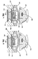
- FIG. 8 illustrates the interconnection of elongated body 14 and handle assembly 12.
- housing 36 includes an annular channel 117 configured to receive an annular rib 118 formed on the proximal end of rotation member 28, which is preferably formed from molded half-sections 28a and 28b. Annular channel 117 and rib 118 permit relative rotation between rotation member 28 and housing 36.
- Elongated body 14 includes inner housing 122 and an outer casing 124. Inner housing 122 is dimensioned to be received within outer casing 124 and includes an internal bore 126 ( FIG. 8 ) which extends therethrough and is dimensioned to slidably receive a first articulation link 123 and control rod 52.
- housing 122 and casing 124 each include a pair of diametrically opposed openings 130 and 128, respectively, which are dimensioned to receive radial projections 132 formed on the distal end of rotation member 28.
- Projections 132 and openings 128 and 130 fixedly secure rotation member 28 and elongated body 14 in relation to each other, both longitudinally and rotatably. Rotation of rotation knob 28 with respect to handle assembly 12 thus results in corresponding rotation of elongated body 14 with respect to handle assembly 12.
- An articulation mechanism 120 is supported on rotatable member 28 and includes articulation lever 30, a cam member 136, a translation member 138, and first articulation link 123 ( FIG. 9 ).
- Articulation lever 30 is pivotably mounted about pivot member 140 which extends outwardly from rotation member 28 and is preferably formed integrally therewith.
- a projection 142 extends downwardly from articulation lever 30 for engagement with cam member 136.
- cam member 136 includes a housing 144 having an elongated slot 146 extending through one side thereof and a stepped camming surface 148 formed in the other side thereof. Each step of camming surface 148 corresponds to a particular degree of articulation of stapling apparatus 10. Although five steps are illustrated, fewer or more steps may be provided.
- Elongated slot 146 is configured to receive projection 142 formed on articulation lever 30.
- Housing 144 includes a distal stepped portion 150 and a proximal stepped portion 152.
- Proximal stepped portion 152 includes a recess 154.
- translation member 138 includes a plurality of ridges 156 which are configured to be slidably received within grooves 158 formed along the inner walls of rotation member 28. Engagement between ridges 156 and grooves 158 prevent relative rotation of rotation member 28 and translation member 138 while permitting relative linear movement.
- the distal end of translation member 138 includes arm 160 which includes an opening 162 configured to receive a finger 164 extending from the proximal end of articulation link 123 (See FIG. 10a ).
- proximal and distal stepped portions 150 and 152 of cam member 136 are positioned beneath flanges 170 and 172 formed on rotation member 28 to restrict cam member 136 to transverse movement with respect to the longitudinal axis of stapling apparatus 10.
- cam member 136 is moved transversely on rotation member 28 to move stepped camming surface 148 transversely relative to pin 166, forcing pin 166 to move proximally or distally along stepped cam surface 148. Since pin 166 is fixedly attached to translation member 138, translation member 138 is moved proximally or distally to effect corresponding proximal or distal movement of first actuation link 123.
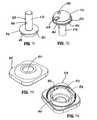
- FIGS. 64-80 illustrate another embodiment of the presently disclosed articulation mechanism shown generally as 420.
- articulation mechanism 420 includes an articulation lever 422, a mechanism cover 424, a biasing member 426, an upper clutch 428, a lower clutch 430, a main shaft 432 and a translation member 434.
- the entire articulation mechanism is supported in a receptacle 436 formed in the top half-section 438a of rotatable member 438 but may also be supported in the handle assembly.
- Receptacle 436 defines a substantially cylindrical throughbore having a shoulder 436a dimensioned to receive and support lower clutch 430.
- Shoulder 436a includes one or more tabs 440.
- lower clutch 430 includes an outer rim portion 442 and an inner circular serrated portion 444.
- Outer rim portion 442 includes one or more cutouts 446 which are dimensioned to receive tabs 440 on shoulder 436a of receptacle 436.
- Lower clutch 430 is positioned within receptacle 436 atop shoulder 436a such that tabs 440 are received within cutouts 446 and lower clutch 430 is prevented from rotating within receptacle 436 ( FIG. 66 ).
- Circular serrated portion 444 includes a series of shallow serrations 448 and three spaced deep serrations 450 ( FIG. 70 ).
- Lower clutch 430 also defines a central throughbore 430a which is dimensioned to receive main shaft 432.
- upper clutch 428 includes a hub portion 452 and a base portion 454.
- Hub portion 452 defines a central throughbore 428a and a channel 456 which is dimensioned to receive a pin 458.
- Pin 458 is inserted through an opening 460 in articulation lever 422 and into channel 456 to rotatably fix articulation lever 422 to upper clutch 428.
- Hub portion 422 also includes an elongated slot 462 which is dimensioned to receive a pin 464.
- Pin 464 is inserted through slot 462 and a hole 466 formed in main shaft 432 to rotatably fix upper clutch 428 to main shaft 432.
- Pin 464 is longitudinally slidable in slot 462 to allow upper clutch 428 to move axially in relation to main shaft 432.
- Base portion 454 of upper clutch includes an upper face 469 and a lower face 468 ( FIG. 68 ) which is positioned in juxtaposed alignment with serrated portion 444 of lower clutch 430.
- Lower face 468 includes a plurality of spaced projections 470 configured to be received within deep and shallow serrations 450 and 448 of lower clutch 430.
- projections 470 have a triangularly shaped cross-section in which the walls defining the triangle are steeper near the apex of the triangle. Such a configuration allows the apex of projections 470 to be received in shallow serrations 448 and substantially the entire projection 470 to be received in deep serrations 450, thus effecting a more secure engagement.
- the shape of projections 470 has two portions and two different engagement surfaces to define two different vertical positions for the mechanism.
- main shaft 432 includes a substantially cylindrical body portion 474 and a disc-shaped base portion 476.
- Base portion 476 defines a cutout 478 ( FIG. 72 ) and includes a cam member or protrusion 480.
- Base portion 476 defines an annular support surface 482 ( FIG. 71 ).
- Body portion 474 is dimensioned to extend through central throughbore 430a of lower clutch 430 and central throughbore 428a of upper clutch 428 such base portion 476 is positioned beneath upper clutch 428 and lower clutch 430 within receptacle 436 of rotatable member 438.
- Base portion 476 also includes a stepped portion 484 defining a shoulder 486. Shoulder 486 is supported on an annular shelf 488 ( FIG. 65 ) formed in receptacle 436 such that main shaft 432 is rotatably supported within receptacle 436 of rotatable member 438.
- mechanism cover 424 defines an opening 490 dimensioned to allow passage of hub portion 452 of upper clutch 428 such that hub portion 452 can be rotatably fixed to articulation lever 422.
- An inner cylindrical portion 492 ( FIG. 74 ) of cover 424 includes cutouts 494.
- cover 424 When cover 424 is placed over receptacle 436 of top half section 43 8a of rotatable member 438, cutouts 494 of cylindrical portion 492 of cover 424 receive tabs 440 and cylindrical portion 492 compresses lower clutch 430 against shoulder 436a ( FIG. 65 ).
- Cover 424 can be secured to rotatable member using any known fastening technique including welding, adhesives or any known mechanical attachment structure, e.g., screws, rivets, etc.
- translation member 434 includes an angled body 496 which defines a cam slot 498, a cutout 500 and an arm 502 having engagement structure 504 configured to engage a proximal end of an articulation link 123 ( FIG. 10A ).
- engagement structure 504 is illustrated as a finger-like projection other mating engagement structures are envisioned to facilitate connection of translation member 434 to articulation link 123 ( FIG. 10A ).
- cam slot 498 of translation member 434 is dimensioned to slidably receive cam member 480 of main shaft 432.
- articulation lever 422 is rotatably fixed to upper clutch 428 and upper clutch 428 is rotatably fixed to body portion 474 of main shaft 432.
- upper clutch 428 and main shaft 432 also rotate to rotate cam member 480 in relation to translation member 434.
- translation member 434 is confined to linear movement within rotatable member 438.
- cam member 480 is driven in rotation
- translation member 434 is forced to move linearly within rotatable member 438. Since translation member 438 is fastened to articulation link 123 ( FIG. 10A ), linear movement of translation member 438 effects linear movement of articulation link 123 to articulate tool assembly 17.
- biasing member 426 is positioned between upper face 469 of base portion 454 of upper clutch 428 and an inner surface 510 of cover 424. Biasing member urges lower face 468 ( FIG. 68 ) of upper clutch 428 into engagement with serrated portion 444 ( FIG. 70 ) of lower clutch 430 such that spaced projections 470 on upper clutch 428 are received within shallow serrations 448 or deep serrations 450 of lower clutch 430. Engagement between projections 470 and serrations 448 and 450 releasably secure articulation mechanism 420 in a fixed position to thereby releasably secure a tool assembly 17 ( FIG. 1 ) at a fixed angle of articulation. See FIG. 76 .
- projections 470 are positioned to be received within deep serrations 450 when tool assembly 17 ( FIG. 1 ) is in its non-articulated position aligned with body portion 14 ( FIG. 1 ). This provides increased resistance to movement of tool assembly 17 from its non-articulated position.
- the deep serrations 450 correspond to the non-articulated position of the tool assembly 17.
- deep serrations may be incorporated into the mechanism to provide other positions with increased resistance to movement.
- a disposable loading unit sensing mechanism extends within stapling apparatus 10 from elongated body 14 into handle assembly 12.
- the sensing mechanism includes a sensor tube 176 which is slidably supported within bore 26 of elongated body 14.
- the distal end of sensor tube 176 is positioned towards the distal end of elongated body 14 and the proximal end of sensor tube 176 is secured within the distal end of a sensor cylinder 176 via a pair of nubs 180.
- the distal end of a sensor link 182 is secured to the proximal end of sensor cylinder 178.
- Sensor link 182 See FIGS.
- sensor link 182 proximally causes bulbous end 184 of sensor link 182 to move distally of camming surface 83a to allow locking member 83 to pivot under the bias of spring 92 from a position permitting firing of stapling apparatus 10 to a blocking position, wherein blocking member 83 is positioned to engage actuation shaft 46 and prevent firing of stapling apparatus 10.
- Sensor link 182 and locking member 83 function to prevent firing of surgical stapling apparatus 10 after a disposable loading unit has been secured to elongated body 14, without first operating firing lockout assembly 80. It is noted that movement of link 182 proximally permits locking member 83 to move to its position shown in FIG. 5 .
- cam member 136 includes recess 154.
- a locking ring 184 having a nub portion 186 configured to be received within recess 154 is positioned about sensor cylinder 178 between a control tab portion 188 and a proximal flange portion 190.
- insertion tip 193 When an articulating disposable loading unit 16b having an extended insertion tip 193 is inserted into the distal end of elongated body 14 of stapling apparatus 10, insertion tip 193 causes tab portion 188 to move proximally into engagement with locking ring 184 to urge locking ring 184 and nub 186 proximally of recess 154 in cam member 136 (See FIG. 12b ). With nub 186 positioned proximally of recess 154, cam member 136 is free to move transversely to effect articulation of stapling apparatus 10. A non-articulating disposable loading unit does not have an extended insertion tip (See FIG. 12a ).
- control rod locking mechanism 190 which is activated during insertion of a disposable loading unit into elongated body 14.
- Control rod locking mechanism 190 includes a blocking plate 192 which is biased distally by a spring 194 and includes a proximal finger 189 having angled cam surface 195.
- a semi-circular engagement member 196 is biased transversely towards control rod 52 by a spring 197.
- Control rod 52 includes an annular recess 199 configured to receive engagement member 196.
- Blocking plate 192 is movable from a distal position spaced from engagement member 196 to a proximal position located behind engagement member 196.
- engagement member 196 In the proximal position, engagement member 196 is prevented from being biased from recess 199 by engagement with blocking plate 192.
- cam surface 195 of blocking plate 192 is engaged by a nub 254 ( FIG. 30 ) on the disposable loading unit 16 as the disposable loading unit is rotated into engagement with elongated body 14 to urge plate 192 to the proximal position.
- Engagement member 196 which is positioned within recess 199, is retained therein by blocking plate 192 while nub 254 engages cam surface 195 to prevent longitudinal movement of control rod 52 during assembly.
- nub 254 on the proximal end of the disposable loading unit 16 passes off cam surface 195 allowing spring 194 to return blocking plate 192 to its distal position to permit subsequent longitudinal movement of control rod 52. It is noted that when the disposable loading unit nub passes off cam surface 195, an audible clicking sound is produced indicating that the disposable loading unit 16 is properly fastened to the elongated body 14.
- disposable loading unit 16 includes a proximal housing portion 200 adapted to releasably engage the distal end of body portion 14 ( FIG. 1 ).
- a mounting assembly 202 is pivotally secured to the distal end of housing portion 200, and is configured to receive the proximal end of tool assembly 17 such that pivotal movement of mounting assembly 202 about an axis perpendicular to the longitudinal axis of housing portion 200 effects articulation of tool assembly 17.
- tool assembly 17 preferably includes anvil assembly 20 and cartridge assembly 18.
- Anvil assembly 20 includes anvil portion 204 having a plurality of staple deforming concavities 206 ( FIG. 22 ) and a cover plate 208 secured to a top surface of anvil portion 204 to define a cavity 210 ( FIG. 24 ) therebetween.
- Cover plate 208 is provided to prevent pinching of tissue during clamping and firing of stapling apparatus 10.
- Cavity 210 is dimensioned to receive a distal end of an axial drive assembly 212 (See FIG. 27 ).
- a longitudinal slot 214 extends through anvil portion 204 to facilitate passage of retention flange 284 of axial drive assembly 212 into the anvil cavity 210.
- a camming surface 209 formed on anvil portion 204 is positioned to engage axial drive assembly 212 to facilitate clamping of tissue 198.
- a pair of pivot members 211 formed on anvil portion 204 are positioned within slots 213 formed in carrier 216 to guide the anvil portion between the open and clamped positions.
- a pair of stabilizing members 215 engage a respective shoulder 217 formed on carrier 216 to prevent anvil portion 204 from sliding axially relative to staple cartridge 220 as camming surface 209 is deformed.
- Cartridge assembly 18 includes a carrier 216 which defines an elongated support channel 218.
- Elongated support channel 218 is dimensioned and configured to receive a staple cartridge 220.
- Corresponding tabs 222 and slots 224 formed along staple cartridge 220 and elongated support channel 218 function to retain staple cartridge 220 within support channel 218.
- a pair of support struts 223 formed on staple cartridge 220 are positioned to rest on side walls of carrier 216 to further stabilize staple cartridge 220 within support channel 218.
- Staple cartridge 220 includes retention slots 225 for receiving a plurality of fasteners 226 and pushers 228.
- a plurality of spaced apart longitudinal slots 230 extend through staple cartridge 220 to accommodate upstanding cam wedges 232 of actuation sled 234.
- a central longitudinal slot 282 extends along the length of staple cartridge 220 to facilitate passage of a knife blade 280.
- actuation sled 234 translates through longitudinal slots 230 of staple cartridge 220 to advance cam wedges 232 into sequential contact with pushers 228, to cause pushers 228 to translate vertically within slots 224 and urge fasteners 226 from slots 224 into the staple deforming cavities 206 of anvil assembly 20.
- mounting assembly 202 includes upper and lower mounting portions 236 and 238.
- Each mounting portion includes a threaded bore 240 on each side thereof dimensioned to receive threaded bolts 242 (See FIG. 21 ) for securing the proximal end of carrier 216 thereto.
- a pair of centrally located pivot members 244 extends between upper and lower mounting portions via a pair of coupling members 246 which engage the distal end of housing portion 200.
- Coupling members 246 each include an interlocking proximal portion 248 configured to be received in grooves 250 formed in the proximal end of housing portion 200 to retain mounting assembly 202 and housing portion 200 in a longitudinally fixed position in relation thereto.
- Housing portion 200 of disposable loading unit 16 includes an upper housing half 250 and a lower housing half 252 contained within an outer casing 251.
- the proximal end of housing half 250 includes engagement nubs 254 for releasably engaging elongated body 14 and an insertion tip 193.
- Nubs 254 form a bayonet type coupling with the distal end of body 14 which will be discussed in further detail below.
- Housing halves 250 and 252 define a channel 253 for slidably receiving axial drive assembly 212.
- a second articulation link 256 is dimensioned to be slidably positioned within a slot 258 formed between housing halves 250 and 252.
- a pair of blow out plates 254 are positioned adjacent the distal end of housing portion 200 adjacent the distal end of axial drive assembly 212 to prevent outward bulging of drive assembly 212 during articulation of tool assembly 17.
- second articulation link 256 includes at least one elongated metallic plate. Preferably, two or more metallic plates are stacked to form link 256.
- the proximal end of articulation link 256 includes a hook portion 258 configured to engage first articulation link 123 (See FIG. 9 ) and the distal end includes a loop 260 dimensioned to engage a projection 262 formed on mounting assembly 202.
- Projection 262 is laterally offset from pivot pin 244 such that linear movement of second articulation link 256 causes mounting assembly 202 to pivot about pivot pins 244 to articulate tool assembly 17.
- axial drive assembly 212 includes an elongated drive beam 266 including a distal working head 268 and a proximal engagement section 270.
- Drive beam 266 may be constructed from a single sheet of material or, preferably, multiple stacked sheets.
- Engagement section 270 includes a pair of engagement fingers 270a and 270b which are dimensioned and configured to mountingly engage a pair of corresponding retention slots 272a and 272b formed in drive member 272.
- Drive member 272 includes a proximal porthole 274 configured to receive the distal end 276 of control rod 52 (See FIG. 35 ) when the proximal end of disposable loading unit 16 is engaged with elongated body 14 of surgical stapling apparatus 10.
- the distal end of drive beam 266 is defined by a vertical support strut 278 which supports a knife blade 280, and an abutment surface 283 which engages the central portion of actuation sled 234 during a stapling procedure.
- Surface 285 at the base of surface 283 is configured to receive a support member 287 slidably positioned along the bottom of the staple cartridge 220.
- Knife blade 280 is positioned to translate slightly behind actuation sled 234 through a central longitudinal slot 282 in staple cartridge 220 ( FIG. 30 ) to form an incision between rows of stapled body tissue.
- a retention flange 284 projects distally from vertical strut 278 and supports a cylindrical cam roller 286 at its distal end.
- Cam roller 286 is dimensioned and configured to engage cam surface 209 on anvil body 204 to clamp anvil portion 204 against body tissue.
- Locking device 288 is pivotally secured to drive member 270 about a pivot pin 290.
- Locking device 288 includes a pair of elongate glides 292 and 294 which define a channel 296.
- a web 298 joins a portion of the upper surfaces of glides 292 and 294, and is configured and dimensioned to fit within elongated slot 298 formed in drive beam 266 at a position distal of drive member 270.
- Horizontal cams 300 and 302 extend from glides 292 and 294 respectively, and are accommodated along an inner surface of lower housing half 252. As best shown in FIG.
- a torsion spring 304 is positioned adjacent drive member 270 and engages horizontal cams 300 and 302 of locking device 288 to normally bias locking device 288 downward toward lower housing half 252 onto ledge 310.
- Locking device 288 translates through housing portion 200 with axial drive assembly 212. Operation of locking device 288 will be described below.
- a disposable loading unit 16 is first secured to the distal end of elongated body 14.
- stapling instrument 10 can be used with articulating and non-articulating disposable loading units having linear rows of staples between about 30mm and about 60mm.
- the distal end 276 of control rod 52 is inserted into insertion tip 193 of disposable loading unit 16, and insertion tip 193 is slid longitudinally into the distal end of elongated body 14 in the direction indicated by arrow "A" in FIG. 41 such that hook portion 258 of second articulation link 256 slides within a channel 310 in elongated body 314.
- Nubs 254 will each be aligned in a respective channel (not shown) in elongated body 14.
- disposable loading unit 16 is rotated in the direction indicated by arrow "B" in FIGS. 41-44 to move hook portion 258 of second articulation link 256 into engagement with finger 164 of first articulation link 123.
- Nubs 254 also forms a bayonet type coupling within annular channel 314 in body 14.
- nubs 254 engage cam surface 195 ( FIG. 41 ) of block plate 192 to initially move plate 192 in the direction indicated by arrow "C" in FIGS.
- nubs 254 disengage from cam surface 195 to allow blocking plate 192 to move in the direction indicated by arrow "D" in FIGS. 42 and 44 from behind engagement member 196 to once again permit longitudinal movement of control rod 52.
- Insertion tip 193 engages and moves sensor tube 176 proximally in the direction indicated by arrow "E” in FIG. 43 .
- proximal movement of sensor tube 176 effects proximal movement of sensor cylinder 178 and sensor link 182 in the direction indicated by arrow "E” in FIG. 43a to pivot locking member 83 counter-clockwise, as indicated by arrow "Y” in FIG. 43a , from a non-blocking position to a position blocking movement of actuation shaft 46.
- tool assembly 17 can be positioned about tissue 320 ( FIG. 45 ).
- stationary handle 24 is moved in the direction indicated by arrow "E” in FIG. 46 against the bias of torsion spring 40 to move driving pawl 42 into engagement with shoulder 322 on actuation shaft 46.
- Engagement between shoulder 322 and driving pawl 42 advances actuation shaft 46 and thus advances control rod 52 distally.
- Control rod 52 is connected at its distal end to axial drive assembly 212 ( FIG. 48 ), including drive beam 266, such that distal movement of control rod 52 effects distal movement of drive beam 266 in the direction indicated by arrow "F” in FIGS.
- movable handle 24 is actuated again, i.e., moved through another stroke.
- stapling apparatus 10 is capable of receiving disposable loading units having linear rows of staples of between about 30mm and about 60mm. Since each stroke of the movable handle 24 preferably advances actuation shaft 46 15mm, and one stroke is required to clamp tissue, the movable handle must be actuated (n+1) strokes to fire staples, where n is the length of the linear rows of staples in the disposable loading unit attached to stapling instrument 10 divided by 15mm.
- firing lockout assembly 80 prior to being able to fire staples, firing lockout assembly 80 ( FIG. 4 ) must be actuated to move locking surface 88 from its blocking position ( FIG. 47 ) to a non-blocking position. This is accomplished by pressing down on plunger 82 to move camming surface 85 into engagement with sidewalls of slot 89 of locking member 83 to pivot locking member 83 in the direction indicated by arrow "G" in FIG. 50 (see also FIG. 5 ). Thereafter, movable handle 24 may be actuated an appropriate number of strokes to advance actuation shaft 46, and thus control rod 52 and drive beam 266, distally in the direction indicated by arrow "H" in FIGS.
- retraction knobs 32 (see FIG. 1 ) are pulled proximally causing pins 66 to move release plate 64 in the direction indicated by arrow "J” in FIG. 53 over teeth 48 to disengage drive pawl 42 from engagement with teeth 48.
- locking pawl 54 is urged by slide plate 102 out of engagement with toothed rack 48 (not shown) to permit actuation shaft 46 to be moved proximally, in the direction indicated by arrow "L", after drive pawl 42 is disengaged from teeth 48.
- emergency return button 112 is pushed in the direction indicated by arrow "Z" in FIG. 54 to disengage locking pawl 54 from toothed rack 48.
- Retraction knobs 32 FIG. 1
- Retraction knobs 32 FIG. 1
- cam member 136 is moved transversely by projection 142 ( FIG. 10 ) in the direction indicated by arrow “N” between flanges 170 and 172 of rotation knob 28. Since translation member 138 is prevented from rotating by ridges 156 ( FIG. 13 ), pin 166, which is fixedly secured to translation member 138, is forced to move along stepped cam surface 148. Movement of pin 166 causes corresponding movement of translation member 138 in the direction indicated by arrow "P" in FIGS. 55 and 56 to advance first articulation link 123 in the distal direction.
- first articulation link 123 engages the proximal end of second articulation link 256 ( FIG. 42 ) which is connected to projection 262 on mounting assembly 202 to advance second link 256 in the direction indicated by arrow "Q" in FIG. 57 .
- Projection 262 is laterally offset from pivot members 244, such that distal advancement of second articulation link 256 causes mounting assembly 202 and thus tool assembly 17 to pivot in the direction indicated by arrow "R" in FIGS. 57 and 58 .
- rotation member 28 can be rotated to rotate elongated body 14 about its longitudinal axis while tool assembly 17 is articulated.
- FIGS. 60-61 illustrate articulation of tool assembly 17 in the opposite direction to that described above.
- pin 66 is forced to move proximally along stepped camming surface 148, moving translation member 138 and first articulation link 123 proximally. Movement of first articulation link 123 proximally, causes second articulation link 256 to move proximally as indicated by arrow "S" in FIG. 58 , to rotate tool assembly 17 in a clockwise direction, as indicated by arrow "T” in FIG. 61 .
- Camming surface 148 includes five step portions 340.
- the third step portion corresponds to the non-articulated tool assembly position, whereas the first and the fifth step portions correspond to articulation of tool assembly 17 to forty-five degrees.
- Each step portion is flat to retain articulation lever 30 in a fixed position when pin 166 is engaged therewith.
- lockout device 288 is shown in its prefired position with horizontal cams 300 and 302 resting on top of projections 330 formed in the sidewalls of lower housing half 252 ( FIG. 37 ). In this position, locking device 288 is held up out of alignment with projection 332 formed in the bottom surface of lower housing half 252, and web 298 is in longitudinal juxtaposition with shelf 334 defined in drive beam 266.
- This configuration permits the anvil 20 ( FIG. 38 ) to be opened and repositioned onto the tissue to be stapled until the surgeon is satisfied with the position without activating locking device 288 to disable the disposable loading unit 16.
- locking device 288 rides off of projections 330 (not shown) and is biased into engagement with base lower housing half 252 by spring 304, distal to projection 332. Locking device 288 remains in this configuration throughout firing of the apparatus.
- locking device 288 Upon retraction of the drive beam 266 in the direction indicated by arrow "U” in FIG. 62 , locking device 288 passes under projections 330 and rides over projection 332 until the distalmost portion of locking device 288 is proximal to projection 332.
- Spring 304 biases locking device 288 into juxtaposed alignment with projection 332, effectively disabling the disposable loading unit. If an attempt is made to reactuate the apparatus, the control rod 52 will abut a proximal end surface of locking device 288 which surface is diagonally sloped to impart a moment about pivot pin 342 such that the distal end of locking device 288 is rotationally urged into contact with projection 332. Continued distal force in the direction indicated by arrow "W” in FIG. 63 , will only serve to increase the moment applied to the locking device thus the locking device will abut projection 332 and inhibit distal movement of the control rod 52.
- the disabled or locked disposable loading unit can be removed from the distal end of elongated body 14 by rotating disposable loading unit 16 in the direction opposite to the direction indicated by arrow "B" in FIGS. 41, 42 and 44 , to disengage hook portion 258 of second articulation link 256 from finger 164 of first articulation link 123, and to disengage nubs 254 from within channel 314 of elongated body 14.
- disposable loading unit 16 can be slid in the direction opposite to that indicated by arrow "A" in FIG. 41 to detach body 14 from disposable loading unit 16.
- each disposable loading unit may include linear rows of staples which vary from about 30mm to about 60mm.
- the stapling apparatus need not apply staples but rather may apply two part fasteners as is known in the art.
- the length of the linear row of staples or fasteners may be modified to meet the requirements of a particular surgical procedure.
- the length of a single stroke of the actuation shaft and/or the length of the linear row of staples and/or fasteners within a disposable loading unit may be varied accordingly. Therefore, the above description should not be construed as limiting, but merely as exemplifications of preferred embodiments. Those skilled in the art will envision other modifications within the scope and spirit of the claims appended thereto.
Abstract
Description
- This application is a continuation-in-part of
U.S. Application Serial No. 11/974,638 filed on October 15, 2007 U.S. Provisional Application Serial No. 60/967,169, filed August 31, 2007 - This application relates to a surgical stapling apparatus, and more particularly, to an articulating mechanism for use with an endoscopic surgical stapling apparatus for sequentially applying a plurality of surgical fasteners to body tissue and optionally incising fastened tissue.
- Surgical devices wherein tissue is first grasped or clamped between opposing jaw structure and then joined by surgical fasteners are well known in the art. In some instruments a knife is provided to cut the tissue which has been joined by the fasteners. The fasteners are typically in the form of surgical staples but two part polymeric fasteners can also be utilized.
- Instruments for this purpose can include two elongated members which are respectively used to capture or clamp tissue. Typically, one of the members carries a staple cartridge which houses a plurality of staples arranged in at least two lateral rows while the other member has an anvil that defines a surface for forming the staple legs as the staples are driven from the staple cartridge. Generally, the stapling operation is effected by cam bars that travel longitudinally through the staple cartridge, with the cam bars acting upon staple pushers to sequentially eject the staples from the staple cartridge. A knife can travel between the staple rows to longitudinally cut and/or open the stapled tissue between the rows of staples. Such instruments are disclosed, for example, in
U.S. Pat. No. 3,079,606 andU.S. Pat. No. 3,490,675 . - A later stapler disclosed in
U.S. Pat. No. 3,499,591 applies a double row of staples on each side of the incision. This is accomplished by providing a disposable loading unit in which a cam member moves through an elongate guide path between two sets of staggered staple carrying grooves. Staple drive members are located within the grooves and are positioned in such a manner so as to be contacted by the longitudinally moving cam member to effect ejection of the staples from the staple cartridge of the disposable loading unit. Other examples of such staplers are disclosed inU.S. Patent Nos. 4,429,695 and5,065,929 . - Each of the instruments described above were designed for use in conventional surgical procedures wherein surgeons have direct manual access to the operative site. However, in endoscopic or laparoscopic procedures, surgery is performed through a small incision or through a narrow cannula inserted through small entrance wounds in the skin. In order to address the specific needs of endoscopic and/or laparoscopic surgical procedures, endoscopic surgical stapling devices have been developed and are disclosed in, for example,
U.S. Pat. Nos. 5,040,715 (Green, et al. );5,307,976 (Olson, et al. );5,312,023 (Green, et al. );5,318,221 (Green, et al. );5,326,013 (Green, et al. ); and5,332,142 (Robinson, et al. ). - U.S. Surgical, the assignee of the present application, has manufactured and marketed endoscopic stapling instruments, such as the Multifire ENDO GIA* 30 instrument, for several years. These instruments have provided significant clinical benefits. Nonetheless, improvements are possible, for example, by reducing the cost and complexity of manufacture.
- Current laparoscopic linear stapling devices are configured to operate with disposable loading units and/or staple cartridges of only one size. For example, individual linear staplers are presently available for applying parallel rows of staples measuring 30mm, 45mm and 60mm in length. Thus, during a normal operation, a surgeon may be required to utilize several different stapling instruments to perform a single laparoscopic surgical procedure. Such practices increase the time, complexity and overall costs associated with laparoscopic surgical procedures. In addition, costs are greater in designing and manufacturing multiple stapler sizes, as opposed to creating a single, multipurpose stapler.
- It would be extremely beneficial to provide a surgical device for use during laparoscopic and/or endoscopic surgical procedures that can be employed with several different sized disposable loading units to reduce the overall costs associated with such procedures. It would also be particularly beneficial if the device could perform multiple tasks, using disposable loading units of varying size and of varying purpose, such as, for example, to staple, clip, cut and/or articulate.
- In making improvements or modifications to the current instruments, it would be highly desirable not to sacrifice any of the important benefits of the MULTIFIRE ENDO GIA* 30 instrument as compared to other commercially available products. For example, any improvement should advantageously provide a fresh knife blade for each firing of the instrument and ensure that the disposable loading unit is securely retained in the stapling instrument unless and until the operating team chooses to remove it. It is desirable for the end effector to be capable of articulating with respect to the elongated shaft of the instrument.
- In accordance with the present disclosure an articulation mechanism is provided including a housing defining a receptacle. The receptacle includes a throughbore. A main shaft is rotatably supported in the receptacle and includes a base portion and a cylindrical body portion. The base portion has an upper support surface and a bottom surface having a cam member extending from the bottom surface through the throughbore of the housing. A lower clutch is non-rotatably supported in the receptacle of the housing. The lower clutch has an outer rim portion and an inner annular serrated portion. The lower clutch defines a throughbore dimensioned to receive the cylindrical body portion of the main shaft. An upper clutch is rotatably fixed to the main shaft and has a base portion having a bottom surface having at least one projection. The upper clutch has a throughbore dimensioned to receive the cylindrical body of the main shaft and is positioned about the cylindrical body portion of the main shaft such that the bottom surface of the upper clutch is in juxtaposed alignment with the annular serrated portion of the lower clutch. In one embodiment, a cover is positioned over the receptacle of the housing. The cover encloses the main shaft, the lower clutch and the upper clutch within the receptacle. The cover defines a throughbore dimensioned to allow passage of the upper clutch. A biasing member is positioned between the cover and the upper clutch. The biasing member urges the bottom surface of the upper clutch into engagement with the serrated portion of the lower clutch. An articulation lever is rotatably fixed to the upper clutch and is rotatable to effect rotation of the upper clutch and the main shaft. A translation member includes a slot dimensioned to receive the cam member which extends from the bottom surface of the base portion of the main shaft such that rotation of the main shaft effects linear movement of the translation member. The at least one projection of the upper clutch and the annular serrated portion of the lower shaft are maintained in releasable engagement to releasably retain the articulation member in a fixed orientation.
- Various preferred embodiments are described herein with reference to the drawings:
-
FIG. 1 is a perspective view of one preferred embodiment of the presently disclosed surgical stapling apparatus; -
FIG. 2 is a top view of the surgical apparatus shown inFIG. 1 ; -
FIG. 3 is a side view of the surgical apparatus shown inFIG. 1 ; -
FIG. 4 is a perspective view with parts separated of the handle assembly of the surgical apparatus shown inFIG. 1 ; -
FIG. 5 is a cross-sectional view of a portion of the firing lockout mechanism shown inFIG. 4 ; -
FIG. 6 is a perspective of the slide plate of the anti-reverse clutch mechanism of the surgical apparatus; -
FIG. 7 is an enlarged perspective view of the anti- reverse clutch mechanism shown inFIG. 1 ; -
FIG. 8 is a side cross-sectional view of the surgical stapling apparatus shown inFIG. 1 in the non-actuated position with the disposable loading unit removed; -
FIG. 9 is a perspective view with parts separated of the rotation member, the articulation mechanism, and the elongated body of the surgical stapling apparatus shown inFIG. 1 ; -
FIG. 10 is an enlarged view of the indicated area of detail shown inFIG. 8 ; -
FIG. 10a is a perspective view of the translation member of the articulating mechanism and the proximal end of the elongated body of the surgical stapling apparatus shown inFIG. 1 ; -
FIG. 10b is an enlarged cross-sectional view of the indicated area of detail ofFIG. 8 ; -
FIG. 10c is a cross-sectional view along section line 10c-10c ofFIG. 8 ; -
FIG. 11 is a perspective view of the cam member of the articulation mechanism of the surgical stapling apparatus shown inFIG. 1 ; -
FIG. 12 is a top view of the cam member of the articulation mechanism of the surgical stapling apparatus shown inFIG. 1 ; -
FIG. 12a is a perspective view of a non-articulating disposable loading unit usable with the surgical stapling apparatus shown inFIG. 1 ; -
FIG. 12b is a perspective view of the preferred articulating disposable loading unit of the surgical stapling apparatus shown inFIG. 1 ; -
FIG. 13 is a cross-sectional view taken along section line 13-13 ofFIG. 10 ; -
FIG. 14 is a cross-sectional view taken along section line 14-14 ofFIG. 10 ; -
FIG. 15 is a cross-sectional view taken along section line 15-15 ofFIG. 10 ; -
FIG. 16 is an enlarged view of the indicated area of detail shown inFIG. 8 ; -
FIG. 17 is a side perspective view of the blocking plate of the surgical stapling apparatus shown inFIG. 1 ; -
FIG. 18 is a top perspective view of the blocking plate of the surgical stapling apparatus shown inFIG. 1 ; -
FIG. 19 is a perspective view of a disposable loading unit usable with the surgical stapling apparatus ofFIG. 1 ; -
FIG. 20 is another perspective view of a disposable loading unit usable with the surgical stapling apparatus ofFIG. 1 ; -
FIG. 21 is a perspective view of the tool assembly of the surgical stapling apparatus ofFIG. 1 with parts separated; -
FIG. 22 is an enlarged perspective view of the distal end of the anvil assembly showing a plurality of staple deforming cavities; -
FIG. 23 is an enlarged perspective view of the distal end of the staple cartridge of the surgical stapling apparatus shown inFIG. 1 ; -
FIG. 24 is a side cross-sectional view taken along section line 24-24 ofFIG. 23 ; -
FIG. 25 is a bottom perspective view of the staple cartridge shown inFIG. 21 ; -
FIG. 26 is an enlarged perspective view of the actuation sled, the pushers and the fasteners shown inFIG. 21 ; -
FIG. 27 is an enlarged perspective view with parts separated of the proximal housing portion and mounting assembly of the disposable loading unit shown inFIG. 19 ; -
FIG. 28 is an enlarged perspective view of the mounting assembly of the disposable loading unit shown inFIG. 19 mounted to a distal end portion of the proximal housing portion; -
FIG. 29 is an enlarged perspective view of the proximal housing portion and the mounting assembly of the disposable loading unit shown inFIG. 19 with the upper housing half removed; -
FIG. 30 is a perspective view of the proximal housing portion and the mounting assembly of the disposable loading unit shown inFIG. 19 with the upper housing half removed; -
FIG. 31 is a perspective view with parts separated of the axial drive assembly; -
FIG. 32 is an enlarged perspective view of the axial drive assembly shown inFIG. 31 ; -
FIG. 33 is an enlarged perspective view of the proximal end of the axial drive assembly shown inFIG. 31 including the locking device; -
FIG. 34 is an enlarged perspective view of the distal end of the axial drive assembly shown inFIG. 31 ; -
FIG. 35 is an enlarged perspective view of the distal end of the elongated body of the stapling apparatus shown inFIG. 1 ; -
FIG. 36 is an enlarged perspective view of the locking device shown inFIG. 33 ; -
FIG. 37 is an enlarged perspective view of a lower housing half of the proximal housing portion of the disposable loading unit shown inFIG. 27 ; -
FIG. 38 is a side cross-sectional view of the disposable loading unit shown inFIG. 20 ; -
FIG. 39 is an enlarged view of the indicated area of detail shown inFIG. 38 ; -
FIG. 40 is a perspective view of the surgical stapling apparatus shown inFIG. 1 with the disposable loading unit ofFIG. 19 detached from the elongated body; -
FIG. 41 is an enlarged perspective view of the disposable loading unit ofFIG. 19 during attachment to the elongated body of the surgical stapling apparatus shown inFIG. 1 ; -
FIG. 42 is another enlarged perspective view of the disposable loading unit ofFIG. 19 during attachment to the elongated body of the surgical stapling apparatus shown inFIG. 1 ; -
FIG. 43 is a cross-sectional view taken along section line 43-43 ofFIG. 41 ; -
FIG. 43a is a side cross-sectional view of the rotation knob, articulation mechanism, and sensing mechanism during insertion of a disposable loading unit into the elongated body of the surgical stapling apparatus; -
FIG. 44 is a cross-sectional view taken along section line 44-44 ofFIG. 42 ; -
FIG. 45 is a side cross-sectional view of the distal end of the disposable loading unit ofFIG. 1 with tissue positioned between the anvil and clamp assemblies; -
FIG. 46 is a side cross-sectional view of the handle assembly with the movable handle in an actuated position; -
FIG. 47 is an enlarged view of the indicated area of detail shown inFIG. 46 ; -
FIG. 48 is a cross-sectional view of the proximal end of the disposable loading unit ofFIG. 19 and the distal end of the elongated body of the surgical stapling apparatus shown inFIG. 1 with the control rod in a partially advanced position; -
FIG. 49 is a cross-sectional view of the tool assembly of the surgical stapling apparatus shown inFIG. 1 positioned about tissue in the clamped position; -
FIG. 50 is a cross-sectional view of the handle assembly of the stapling apparatus ofFIG. 1 during the clamping stroke of the apparatus; -
FIG. 51 is a side cross-sectional view of the distal end of the tool assembly of the stapling apparatus shown inFIG. 1 during firing of the apparatus; -
FIG. 52 is a side cross-sectional view of the distal end of the tool assembly of the stapling apparatus shown inFIG. 1 after firing of the apparatus; -
FIG. 53 is a side cross-sectional view of the handle assembly of the apparatus during retraction of the actuation shaft; -
FIG. 54 is a side cross-sectional view of the handle assembly of the stapling apparatus during actuation of the emergency release button; -
FIG. 55 is a top view of the articulation mechanism of the surgical stapling apparatus; -
FIG. 56 is a side cross-sectional view of the articulation mechanism and rotation member of the surgical stapling apparatus shown inFIG. 1 ; -
FIG. 57 is a top view of the distal end of the elongated body, the mounting assembly, and the proximal end of the tool assembly during articulation of the stapling apparatus; -
FIG. 58 is a perspective view of the surgical stapling apparatus during articulation of the tool assembly; -
FIG. 59 is a perspective view of the surgical stapling apparatus during articulation and rotation of the tool assembly; -
FIG. 60 is a top view of the distal end of the disposable loading unit immediately prior to articulation; -
FIG. 61 is a top view of the distal end of the elongated body, the mounting assembly, and the proximal end of the tool assembly during articulation of the stapling apparatus; -
FIG. 62 is a partial cross-sectional view of a portion of the disposable loading unit during retraction of the locking device; and -
FIG. 63 is a partial cross-sectional view of a portion of the disposable loading unit with the locking device in the locked position. -
FIG. 64 is a perspective view of another embodiment of the presently disclosed articulation mechanism; -
FIG. 65 is a perspective view of the articulation mechanism shown inFIG. 64 with parts separated; -
FIG. 66 is a perspective view of the rotatable member of the articulation mechanism shown inFIG. 64 with the lower clutch positioned in the receptacle of the rotatable member; -
FIG. 67 is a bottom view of the upper clutch and translation member of the articulation mechanism shown inFIG. 65 ; -
FIG. 68 is a bottom side perspective view of the upper clutch of the articulation mechanism shown inFIG. 65 ; -
FIG. 69 is a perspective view from the top of the upper clutch shown inFIG. 68 ; -
FIG. 70 is a top perspective view of the lower clutch of the articulation mechanism shown inFIG. 65 ; -
FIG. 71 is a top perspective view of the main shaft of the articulation mechanism shown inFIG. 65 ; -
FIG. 72 is a bottom perspective view of the main shaft shown inFIG. 71 ; -
FIG. 73 is a top perspective view of the cover of the articulation mechanism shown inFIG. 65 ; -
FIG. 74 is a bottom perspective view of the cover shown inFIG. 73 ; -
FIG. 75 is a cross-sectional view of the articulation mechanism shown inFIG. 64 with the articulation mechanism in a non-articulated position; -
FIG. 76 is a cross-sectional view taken along section lines 76-76 ofFIG. 75 ; -
FIG. 77 is a top view of the articulation mechanism shown inFIG. 64 with the articulation lever rotated; -
FIG. 78 is a cross-sectional view of the articulation mechanism shown inFIG. 64 with the articulation lever rotated as shown inFIG. 77 ; -
FIG. 79 is a cross-sectional view taken along section lines 79-79 ofFIG. 78 ; and -
FIG. 80 is a cross-sectional view of the articulation mechanism shown inFIG. 64 with the articulation lever rotated and the upper clutch projection reengaged with the serrations of the lower clutch. - Preferred embodiments of the presently disclosed endoscopic surgical stapling apparatus will now be described in detail with reference to the drawings, in which like reference numerals designate identical or corresponding elements in each of the several views.
- In the drawings and in the description that follows, the term "proximal", as is traditional, will refer to the end of the stapling apparatus which is closest to the operator, while the term distal will refer to the end of the apparatus which is furthest from the operator.
-
FIGS. 1-3 illustrate one embodiment of the presently disclosed surgical stapling apparatus shown generally as 10. Briefly,surgical stapling apparatus 10 includes ahandle assembly 12 and anelongated body 14. A disposable loading unit orDLU 16 is releasably secured to a distal end ofelongated body 14.Disposable loading unit 16 includes atool assembly 17 having acartridge assembly 18 housing a plurality of surgical staples and ananvil assembly 20 movably secured in relation tocartridge assembly 18.Disposable loading unit 16 is configured to apply linear rows of staples measuring from about 30mm to about 60mm in length. Disposable loading units having linear rows of staples of other lengths are also envisioned, e.g., 45mm. Handleassembly 12 includes astationary handle member 22, amovable handle member 24, and abarrel portion 26. Arotatable member 28 is preferably mounted on the forward end ofbarrel portion 26 to facilitate rotation ofelongated body 14 with respect to handleassembly 12. Anarticulation lever 30 is also preferably mounted on the forward end ofbarrel portion 26 adjacentrotatable knob 28 to facilitate articulation oftool assembly 17. A pair of retraction knobs 32 are movably positioned alongbarrel portion 26 to returnsurgical stapling apparatus 10 to a retracted position, as will be described in detail below. - Referring to
FIG. 4 , handleassembly 12 includeshousing 36, which is preferably formed from molded housing half-sections 36a and 36b, which formsstationary handle member 22 andbarrel portion 26 of handle assembly 12 (SeeFIG. 1 ).Movable handle member 24 is pivotably supported between housing half-sections 36a and 36b aboutpivot pin 38. A biasingmember 40, which is preferably a torsion spring, biasesmovable handle 24 away fromstationary handle 22. Anactuation shaft 46 is supported withinbarrel portion 26 ofhousing 36 and includes atoothed rack 48. A drivingpawl 42 having arack engagement finger 43 with laterally extendingwings movable handle 24 about apivot pin 44. A biasingmember 50, which is also preferably a torsion spring, is positioned to urgeengagement finger 43 of drivingpawl 42 towardstoothed rack 48 ofactuation shaft 46.Movable handle 24 is pivotable to moveengagement finger 43 of drivingpawl 42 into contact withtoothed rack 48 ofactuation shaft 46 to advance the actuation shaft linearly in the distal direction. The forward end ofactuation shaft 46 rotatably receives theproximal end 49 of acontrol rod 52 such that linear advancement ofactuation shaft 46 causes corresponding linear advancement ofcontrol rod 52. A lockingpawl 54 having a rack engagement member 55 is pivotably mounted withinhousing 36 aboutpivot pin 57 and is biased towardstoothed rack 48 by biasingmember 56, which is also preferably a torsion spring. Engagement member 55 of lockingpawl 54 is movable into engagement withtoothed rack 48 to retainactuation shaft 46 in a longitudinally fixed position. - A
retraction mechanism 58 which includes a pair of retractor knobs 32 (SeeFIG. 1 ) is connected to the proximal end ofactuation shaft 46 by acoupling rod 60. Couplingrod 60 includes right and leftengagement portions 62a and 62b for receivingretractor knobs 32 and a central portion 62c which is dimensioned and configured to translate within a pair oflongitudinal slots 34a formed inactuation shaft 46 adjacent the proximal end thereof. Arelease plate 64 is operatively associated withactuation shaft 46 and is mounted for movement with respect thereto in response to manipulation of retractor knobs 32. A pair of spaced apart pins 66 extend outwardly from a lateral face ofactuation shaft 46 to engage a pair of correspondingangled cam slots 68 formed inrelease plate 64. Upon rearward movement of retractor knobs 32, pins 66 can releaseplate 64 downwardly with respect toactuation shaft 46 and with respect totoothed rack 48 such that the bottom portion ofrelease plate 64 extends belowtoothed rack 48 to disengageengagement finger 43 of drivingpawl 42 fromtoothed rack 48. Atransverse slot 70 is formed at the proximal end ofrelease plate 64 to accommodate the central portion 62c ofcoupling rod 60, and elongated slots 34 (SeeFIG. 1 ) are defined in thebarrel section 26 ofhandle assembly 12 to accommodate the longitudinal translation ofcoupling rod 60 as retraction knobs 32 are pulled rearwardly to retractactuation shaft 46 and thus retractcontrol rod 52 rearwardly.Actuation shaft 46 is biased proximally byspring 72 which is secured at one end tocoupling rod portion 62 viaconnector 74 and at the other end to post 76 onactuation shaft 46. - Referring also to
FIG. 5 , handleassembly 12 includes afiring lockout assembly 80 which includes aplunger 82 and apivotable locking member 83.Plunger 82 is biased to a central position by biasingsprings 84 and includes annular tapered camming surfaces 85. Each end ofplunger 82 extends through housing 36 (SeeFIG. 1 ) adjacent an upper end ofstationary handle 22.Pivotable locking member 83 is pivotably attached at its distal end between housing half-sections 36a and 36b aboutpivot pin 86 and includes a lockingsurface 88 andproximal extension 90 having aslot 89 formed therein. Lockingmember 83 is biased byspring 92 counter-clockwise (as viewed inFIG. 4 ) to move lockingsurface 88 to a position to abut the distal end ofactuation shaft 46 to prevent advancement ofshaft 46 and subsequent firing of staplingapparatus 10. Annular taperedcamming surface 85 is positioned to extend into taperedslot 89 inproximal extension 90. Lateral movement ofplunger 82 in either direction against the bias of eitherspring 84 moves taperedcamming surface 85 into engagement with the sidewalls of taperedslot 89 to pivot lockingmember 83 clockwise aboutpivot pin 86, as viewed inFIG. 4 , to move blockingsurface 88 to a position to permit advancement ofactuation shaft 46 and thus firing of staplingapparatus 10. Blockingsurface 88 is retained in this position byrecesses 87 which receive the tapered tip ofcamming surface 85 to lock lockingmember 83 in a counter-clockwise position. Operation of firinglockout assembly 80 will be further illustrated below. - Referring to
FIGS. 4 ,6, and 7 , handlemechanism 12 also includes an anti-reverse clutch mechanism which includes afirst gear 94 rotatably mounted on afirst shaft 96, andsecond gear 98 mounted on asecond shaft 100, and a slide plate 102 (FIGS. 6 and 7 ) slidably mounted withinhousing 36.Slide plate 102 includes anelongated slot 104 dimensioned and configured to be slidably positioned about lockingpawl pivot pin 57, agear plate 106 configured to mesh with the teeth ofsecond gear 98, and acam surface 108. In the retracted position,cam surface 108 ofslide plate 102 engages lockingpawl 54 to prevent lockingpawl 54 from engagingtoothed rack 48.Actuation shaft 46 includes a distal set ofgear teeth 110a spaced from a proximal set ofgear teeth 110b positioned to engagefirst gear 94 ofactuation shaft 46 during movement ofactuation shaft 46. Whenactuation shaft 46 is advanced by pivotingmovable handle 24 aboutpivot pin 38,distal gear teeth 110a onactuation shaft 46 mesh with and rotatefirst gear 94 andfirst shaft 96.First shaft 96 is connected tosecond shaft 100 by spring clutch assembly such that rotation offirst shaft 96 will cause corresponding rotation ofsecond shaft 100. Rotation ofsecond shaft 100 causes corresponding rotation ofsecond gear 98 which is engaged withgear plate 106 onslide plate 102 to cause linear advancement ofslide plate 102. Linear advancement ofslide plate 102 is limited to the length ofelongated slot 104. When slide plate has been advanced the length ofslot 104,cam surface 108releases locking pawl 54 such that it is moved into engagement withtoothed rack 48. Continued advancement ofactuation shaft 46 eventually movesgear teeth 110b into engagement withgear plate 106. However, sinceslide plate 102 is longitudinally fixed in position, the spring clutch is forced to release, such that continued distal advancement ofactuation shaft 46 is permitted. - When
actuation shaft 46 is returned to the retracted position (by pullingretraction knobs 34 proximally, as discussed above)gear teeth 110b engagefirst gear 94 to rotatesecond gear 98 in the reverse direction to retractslide member 102 proximally withinhousing 36. Proximal movement ofslide member 102 advancescam surface 108 into lockingpawl 54 prior to engagement between lockingpawl 54 andtoothed rack 48 to urge lockingpawl 54 to a position to permit retraction ofactuation shaft 46. - Referring again to
FIG. 4 , handleassembly 12 includes anemergency return button 112 pivotally mounted withinhousing 36 about apivot member 114 supported between housing half-sections 36a and 36b.Return button 112 includes an externally positionedmember 116 positioned on the proximal end ofbarrel portion 26.Member 116 is movable aboutpivot member 114 into engagement with the proximal end of lockingpawl 54 to urge rack engagement member 55 out of engagement withtoothed rack 48 to permit retraction ofactuation shaft 46 during the firing stroke of thestapling apparatus 10. As discussed above, during the clamping portion of advancement ofactuation shaft 46,slide plate 102 disengages pawl 54 fromrack 48 and thus actuation ofreturn button 112 is not necessary to retract theactuation shaft 46. -
FIG. 8 illustrates the interconnection ofelongated body 14 and handleassembly 12. Referring toFIGS. 8-10 ,housing 36 includes anannular channel 117 configured to receive anannular rib 118 formed on the proximal end ofrotation member 28, which is preferably formed from molded half-sections 28a and 28b.Annular channel 117 andrib 118 permit relative rotation betweenrotation member 28 andhousing 36.Elongated body 14 includesinner housing 122 and anouter casing 124.Inner housing 122 is dimensioned to be received withinouter casing 124 and includes an internal bore 126 (FIG. 8 ) which extends therethrough and is dimensioned to slidably receive afirst articulation link 123 andcontrol rod 52. The proximal end ofhousing 122 andcasing 124 each include a pair of diametricallyopposed openings radial projections 132 formed on the distal end ofrotation member 28.Projections 132 andopenings secure rotation member 28 andelongated body 14 in relation to each other, both longitudinally and rotatably. Rotation ofrotation knob 28 with respect to handleassembly 12 thus results in corresponding rotation ofelongated body 14 with respect to handleassembly 12. - An
articulation mechanism 120 is supported onrotatable member 28 and includesarticulation lever 30, acam member 136, atranslation member 138, and first articulation link 123 (FIG. 9 ).Articulation lever 30 is pivotably mounted aboutpivot member 140 which extends outwardly fromrotation member 28 and is preferably formed integrally therewith. Aprojection 142 extends downwardly fromarticulation lever 30 for engagement withcam member 136. - Referring temporarily to
FIGS. 11 and 12 ,cam member 136 includes ahousing 144 having anelongated slot 146 extending through one side thereof and a steppedcamming surface 148 formed in the other side thereof. Each step ofcamming surface 148 corresponds to a particular degree of articulation of staplingapparatus 10. Although five steps are illustrated, fewer or more steps may be provided.Elongated slot 146 is configured to receiveprojection 142 formed onarticulation lever 30.Housing 144 includes a distal steppedportion 150 and a proximal steppedportion 152. Proximal steppedportion 152 includes arecess 154. - Referring again to
FIGS. 8-10 and also toFIGS. 13-15 ,translation member 138 includes a plurality ofridges 156 which are configured to be slidably received withingrooves 158 formed along the inner walls ofrotation member 28. Engagement betweenridges 156 andgrooves 158 prevent relative rotation ofrotation member 28 andtranslation member 138 while permitting relative linear movement. The distal end oftranslation member 138 includesarm 160 which includes anopening 162 configured to receive afinger 164 extending from the proximal end of articulation link 123 (SeeFIG. 10a ). Apin 166 having ahousing 168 constructed from a non-abrasive material, e.g., teflon, is secured totranslation member 138 and dimensioned to be received within steppedcamming surface 148. - In an assembled condition, proximal and distal stepped
portions cam member 136 are positioned beneathflanges rotation member 28 to restrictcam member 136 to transverse movement with respect to the longitudinal axis of staplingapparatus 10. Whenarticulation lever 30 is pivoted aboutpivot member 140,cam member 136 is moved transversely onrotation member 28 to move steppedcamming surface 148 transversely relative to pin 166, forcingpin 166 to move proximally or distally along steppedcam surface 148. Sincepin 166 is fixedly attached totranslation member 138,translation member 138 is moved proximally or distally to effect corresponding proximal or distal movement offirst actuation link 123. -
FIGS. 64-80 illustrate another embodiment of the presently disclosed articulation mechanism shown generally as 420. Referring toFIGS. 64 and65 ,articulation mechanism 420 includes anarticulation lever 422, amechanism cover 424, a biasingmember 426, anupper clutch 428, alower clutch 430, amain shaft 432 and atranslation member 434. The entire articulation mechanism is supported in areceptacle 436 formed in the top half-section 438a ofrotatable member 438 but may also be supported in the handle assembly.Receptacle 436 defines a substantially cylindrical throughbore having a shoulder 436a dimensioned to receive and supportlower clutch 430. Shoulder 436a includes one ormore tabs 440. - Referring also to
FIGS. 66 and70 ,lower clutch 430 includes an outer rim portion 442 and an inner circularserrated portion 444. Outer rim portion 442 includes one ormore cutouts 446 which are dimensioned to receivetabs 440 on shoulder 436a ofreceptacle 436.Lower clutch 430 is positioned withinreceptacle 436 atop shoulder 436a such thattabs 440 are received withincutouts 446 andlower clutch 430 is prevented from rotating within receptacle 436 (FIG. 66 ). Circularserrated portion 444 includes a series ofshallow serrations 448 and three spaced deep serrations 450 (FIG. 70 ). Theseserrations articulation lever 422 at a plurality of different articulated positions as will be discussed in further detail below. Lower clutch 430 also defines acentral throughbore 430a which is dimensioned to receivemain shaft 432. - Referring to
FIGS. 65 ,68 and 69 ,upper clutch 428 includes ahub portion 452 and abase portion 454.Hub portion 452 defines acentral throughbore 428a and achannel 456 which is dimensioned to receive apin 458.Pin 458 is inserted through anopening 460 inarticulation lever 422 and intochannel 456 to rotatably fixarticulation lever 422 toupper clutch 428.Hub portion 422 also includes anelongated slot 462 which is dimensioned to receive apin 464.Pin 464 is inserted throughslot 462 and ahole 466 formed inmain shaft 432 to rotatably fixupper clutch 428 tomain shaft 432.Pin 464 is longitudinally slidable inslot 462 to allow upper clutch 428 to move axially in relation tomain shaft 432. -
Base portion 454 of upper clutch includes anupper face 469 and a lower face 468 (FIG. 68 ) which is positioned in juxtaposed alignment withserrated portion 444 oflower clutch 430.Lower face 468 includes a plurality of spacedprojections 470 configured to be received within deep andshallow serrations lower clutch 430. In one embodiment,projections 470 have a triangularly shaped cross-section in which the walls defining the triangle are steeper near the apex of the triangle. Such a configuration allows the apex ofprojections 470 to be received inshallow serrations 448 and substantially theentire projection 470 to be received indeep serrations 450, thus effecting a more secure engagement. The shape ofprojections 470 has two portions and two different engagement surfaces to define two different vertical positions for the mechanism. - Referring to
FIGS. 65 ,71 and 72 ,main shaft 432 includes a substantiallycylindrical body portion 474 and a disc-shapedbase portion 476.Base portion 476 defines a cutout 478 (FIG. 72 ) and includes a cam member orprotrusion 480.Base portion 476 defines an annular support surface 482 (FIG. 71 ).Body portion 474 is dimensioned to extend through central throughbore 430a oflower clutch 430 and central throughbore 428a of upper clutch 428such base portion 476 is positioned beneathupper clutch 428 andlower clutch 430 withinreceptacle 436 ofrotatable member 438.Base portion 476 also includes a steppedportion 484 defining ashoulder 486.Shoulder 486 is supported on an annular shelf 488 (FIG. 65 ) formed inreceptacle 436 such thatmain shaft 432 is rotatably supported withinreceptacle 436 ofrotatable member 438. - Referring to
FIGS. 65 ,73 and 74 ,mechanism cover 424 defines anopening 490 dimensioned to allow passage ofhub portion 452 of upper clutch 428 such thathub portion 452 can be rotatably fixed toarticulation lever 422. An inner cylindrical portion 492 (FIG. 74 ) ofcover 424 includescutouts 494. Whencover 424 is placed overreceptacle 436 oftop half section 43 8a ofrotatable member 438,cutouts 494 ofcylindrical portion 492 ofcover 424 receivetabs 440 andcylindrical portion 492 compresses lower clutch 430 against shoulder 436a (FIG. 65 ). Cover 424 can be secured to rotatable member using any known fastening technique including welding, adhesives or any known mechanical attachment structure, e.g., screws, rivets, etc. - Referring to
FIG. 65 ,translation member 434 includes anangled body 496 which defines acam slot 498, a cutout 500 and anarm 502 havingengagement structure 504 configured to engage a proximal end of an articulation link 123 (FIG. 10A ). Although theengagement structure 504 is illustrated as a finger-like projection other mating engagement structures are envisioned to facilitate connection oftranslation member 434 to articulation link 123 (FIG. 10A ). - Referring also to
FIG. 67 ,cam slot 498 oftranslation member 434 is dimensioned to slidably receivecam member 480 ofmain shaft 432. As discussed above,articulation lever 422 is rotatably fixed toupper clutch 428 andupper clutch 428 is rotatably fixed tobody portion 474 ofmain shaft 432. Thus, whenarticulation lever 422 is rotated,upper clutch 428 andmain shaft 432 also rotate to rotatecam member 480 in relation totranslation member 434. Although not shown,translation member 434 is confined to linear movement withinrotatable member 438. As such, whencam member 480 is driven in rotation,translation member 434 is forced to move linearly withinrotatable member 438. Sincetranslation member 438 is fastened to articulation link 123 (FIG. 10A ), linear movement oftranslation member 438 effects linear movement of articulation link 123 to articulatetool assembly 17. - Referring now to
FIGS. 65 and75 , biasingmember 426 is positioned betweenupper face 469 ofbase portion 454 ofupper clutch 428 and aninner surface 510 ofcover 424. Biasing member urges lower face 468 (FIG. 68 ) of upper clutch 428 into engagement with serrated portion 444 (FIG. 70 ) of lower clutch 430 such that spacedprojections 470 onupper clutch 428 are received withinshallow serrations 448 ordeep serrations 450 oflower clutch 430. Engagement betweenprojections 470 andserrations secure articulation mechanism 420 in a fixed position to thereby releasably secure a tool assembly 17 (FIG. 1 ) at a fixed angle of articulation. SeeFIG. 76 . - Referring to
FIGS. 77-80 , whenarticulation lever 422 is rotated, (as discussed above)upper clutch 428 andmain shaft 432 are driven in rotation. Whenbase portion 454 ofupper clutch 428 is rotated in relation toserrated portion 444 of lower clutch 428, thetriangular projections 470 are driven against angledserrations upper clutch 428 is urged upwardly against the bias of biasing member 426 (FIG. 78 ) to disengageprojections 470 fromserrations 448 or 450 (FIG. 79 ), to allow rotation ofupper clutch 428, and thus,main shaft 432. Thereafter, biasingmember 426 urges upper clutch downwardly to urgeprojection 470 back into engagement with the next serration (FIG. 80 ). It is noted,projections 470 are positioned to be received withindeep serrations 450 when tool assembly 17 (FIG. 1 ) is in its non-articulated position aligned with body portion 14 (FIG. 1 ). This provides increased resistance to movement oftool assembly 17 from its non-articulated position. Desirably, thedeep serrations 450 correspond to the non-articulated position of thetool assembly 17. However, deep serrations may be incorporated into the mechanism to provide other positions with increased resistance to movement. - Referring to
FIGS. 8-10 and16 , a disposable loading unit sensing mechanism extends within staplingapparatus 10 fromelongated body 14 intohandle assembly 12. The sensing mechanism includes asensor tube 176 which is slidably supported withinbore 26 ofelongated body 14. The distal end ofsensor tube 176 is positioned towards the distal end ofelongated body 14 and the proximal end ofsensor tube 176 is secured within the distal end of asensor cylinder 176 via a pair ofnubs 180. The distal end of asensor link 182 is secured to the proximal end ofsensor cylinder 178. Sensor link 182 (SeeFIGS. 8a and 8c ) has abulbous end 184 which engages a camming surface 83a onpivotable locking member 83. When a disposable loading unit (not shown) is inserted in the distal end ofelongated body 14, the disposable loading unit engages the distal end 177 ofsensor tube 176 to drivesensor tube 176 proximally, and thereby drivesensor cylinder 178 andsensor link 182 proximally. Movement ofsensor link 182 proximally causesbulbous end 184 ofsensor link 182 to move distally of camming surface 83a to allow lockingmember 83 to pivot under the bias ofspring 92 from a position permitting firing of staplingapparatus 10 to a blocking position, wherein blockingmember 83 is positioned to engageactuation shaft 46 and prevent firing of staplingapparatus 10.Sensor link 182 and lockingmember 83 function to prevent firing ofsurgical stapling apparatus 10 after a disposable loading unit has been secured toelongated body 14, without first operatingfiring lockout assembly 80. It is noted that movement oflink 182 proximallypermits locking member 83 to move to its position shown inFIG. 5 . - Referring again to
FIGS. 9-12 ,cam member 136 includesrecess 154. A lockingring 184 having anub portion 186 configured to be received withinrecess 154 is positioned aboutsensor cylinder 178 between acontrol tab portion 188 and aproximal flange portion 190. Aspring 192 positioned betweenflange portion 190 and lockingring 184 urges locking ring distally aboutsensor cylinder 178. When an articulating disposable loading unit 16b having an extendedinsertion tip 193 is inserted into the distal end ofelongated body 14 of staplingapparatus 10,insertion tip 193causes tab portion 188 to move proximally into engagement with lockingring 184 to urge lockingring 184 andnub 186 proximally ofrecess 154 in cam member 136 (SeeFIG. 12b ). Withnub 186 positioned proximally ofrecess 154,cam member 136 is free to move transversely to effect articulation of staplingapparatus 10. A non-articulating disposable loading unit does not have an extended insertion tip (SeeFIG. 12a ). As such, when a non-articulating disposable loading unit is inserted inelongated body 14,sensor cylinder 178 is not retracted proximally a sufficient distance to move nub 186 fromrecess 154. Thus,cam member 136 is prevented from moving transversely by nub 186 of lockingring 184 which is positioned inrecess 154 andarticulation lever 30 is locked in its central position. - Referring to
FIGS. 16-18 , the distal end ofelongated body 14 includes a controlrod locking mechanism 190 which is activated during insertion of a disposable loading unit intoelongated body 14. Controlrod locking mechanism 190 includes a blockingplate 192 which is biased distally by aspring 194 and includes aproximal finger 189 having angledcam surface 195. Asemi-circular engagement member 196 is biased transversely towardscontrol rod 52 by aspring 197.Control rod 52 includes anannular recess 199 configured to receiveengagement member 196. Blockingplate 192 is movable from a distal position spaced fromengagement member 196 to a proximal position located behindengagement member 196. In the proximal position,engagement member 196 is prevented from being biased fromrecess 199 by engagement with blockingplate 192. During insertion of a disposable loading unit 16 (SeeFIG. 1 ) into the distal end ofelongated body 14, as will be described in further detail below,cam surface 195 of blockingplate 192 is engaged by a nub 254 (FIG. 30 ) on thedisposable loading unit 16 as the disposable loading unit is rotated into engagement withelongated body 14 to urgeplate 192 to the proximal position.Engagement member 196, which is positioned withinrecess 199, is retained therein by blockingplate 192 while nub 254 engagescam surface 195 to prevent longitudinal movement ofcontrol rod 52 during assembly. When thedisposable loading unit 16 is properly positioned with respect to theelongated body 14,nub 254 on the proximal end of thedisposable loading unit 16 passes offcam surface 195 allowingspring 194 to return blockingplate 192 to its distal position to permit subsequent longitudinal movement ofcontrol rod 52. It is noted that when the disposable loading unit nub passes offcam surface 195, an audible clicking sound is produced indicating that thedisposable loading unit 16 is properly fastened to theelongated body 14. - Referring to
FIGS. 19 and 20 ,disposable loading unit 16 includes aproximal housing portion 200 adapted to releasably engage the distal end of body portion 14 (FIG. 1 ). A mountingassembly 202 is pivotally secured to the distal end ofhousing portion 200, and is configured to receive the proximal end oftool assembly 17 such that pivotal movement of mountingassembly 202 about an axis perpendicular to the longitudinal axis ofhousing portion 200 effects articulation oftool assembly 17. - Referring to
FIGS. 21-26 ,tool assembly 17 preferably includesanvil assembly 20 andcartridge assembly 18.Anvil assembly 20 includesanvil portion 204 having a plurality of staple deforming concavities 206 (FIG. 22 ) and acover plate 208 secured to a top surface ofanvil portion 204 to define a cavity 210 (FIG. 24 ) therebetween.Cover plate 208 is provided to prevent pinching of tissue during clamping and firing of staplingapparatus 10.Cavity 210 is dimensioned to receive a distal end of an axial drive assembly 212 (SeeFIG. 27 ). Alongitudinal slot 214 extends throughanvil portion 204 to facilitate passage ofretention flange 284 ofaxial drive assembly 212 into theanvil cavity 210. Acamming surface 209 formed onanvil portion 204 is positioned to engageaxial drive assembly 212 to facilitate clamping oftissue 198. A pair ofpivot members 211 formed onanvil portion 204 are positioned withinslots 213 formed incarrier 216 to guide the anvil portion between the open and clamped positions. A pair of stabilizing members 215 engage arespective shoulder 217 formed oncarrier 216 to preventanvil portion 204 from sliding axially relative tostaple cartridge 220 ascamming surface 209 is deformed. -
Cartridge assembly 18 includes acarrier 216 which defines anelongated support channel 218.Elongated support channel 218 is dimensioned and configured to receive astaple cartridge 220. Correspondingtabs 222 andslots 224 formed alongstaple cartridge 220 andelongated support channel 218 function to retainstaple cartridge 220 withinsupport channel 218. A pair of support struts 223 formed onstaple cartridge 220 are positioned to rest on side walls ofcarrier 216 to further stabilizestaple cartridge 220 withinsupport channel 218. -
Staple cartridge 220 includesretention slots 225 for receiving a plurality offasteners 226 andpushers 228. A plurality of spaced apartlongitudinal slots 230 extend throughstaple cartridge 220 to accommodateupstanding cam wedges 232 ofactuation sled 234. A centrallongitudinal slot 282 extends along the length ofstaple cartridge 220 to facilitate passage of aknife blade 280. During operation ofsurgical stapler 10,actuation sled 234 translates throughlongitudinal slots 230 ofstaple cartridge 220 to advancecam wedges 232 into sequential contact withpushers 228, to causepushers 228 to translate vertically withinslots 224 andurge fasteners 226 fromslots 224 into thestaple deforming cavities 206 ofanvil assembly 20. - Referring to
FIGS. 27 and28 , mountingassembly 202 includes upper and lower mountingportions bore 240 on each side thereof dimensioned to receive threaded bolts 242 (SeeFIG. 21 ) for securing the proximal end ofcarrier 216 thereto. A pair of centrally located pivot members 244 (SeeFIG. 21 ) extends between upper and lower mounting portions via a pair ofcoupling members 246 which engage the distal end ofhousing portion 200. Couplingmembers 246 each include an interlocking proximal portion 248 configured to be received ingrooves 250 formed in the proximal end ofhousing portion 200 to retain mountingassembly 202 andhousing portion 200 in a longitudinally fixed position in relation thereto. -
Housing portion 200 ofdisposable loading unit 16 includes anupper housing half 250 and alower housing half 252 contained within anouter casing 251. The proximal end ofhousing half 250 includesengagement nubs 254 for releasably engagingelongated body 14 and aninsertion tip 193.Nubs 254 form a bayonet type coupling with the distal end ofbody 14 which will be discussed in further detail below. Housing halves 250 and 252 define a channel 253 for slidably receivingaxial drive assembly 212. Asecond articulation link 256 is dimensioned to be slidably positioned within aslot 258 formed betweenhousing halves plates 254 are positioned adjacent the distal end ofhousing portion 200 adjacent the distal end ofaxial drive assembly 212 to prevent outward bulging ofdrive assembly 212 during articulation oftool assembly 17. - Referring to
FIGS. 29-30 ,second articulation link 256 includes at least one elongated metallic plate. Preferably, two or more metallic plates are stacked to formlink 256. The proximal end ofarticulation link 256 includes ahook portion 258 configured to engage first articulation link 123 (SeeFIG. 9 ) and the distal end includes aloop 260 dimensioned to engage aprojection 262 formed on mountingassembly 202.Projection 262 is laterally offset frompivot pin 244 such that linear movement ofsecond articulation link 256causes mounting assembly 202 to pivot about pivot pins 244 to articulatetool assembly 17. - Referring also to
FIGS. 31-34 ,axial drive assembly 212 includes anelongated drive beam 266 including adistal working head 268 and aproximal engagement section 270.Drive beam 266 may be constructed from a single sheet of material or, preferably, multiple stacked sheets.Engagement section 270 includes a pair ofengagement fingers 270a and 270b which are dimensioned and configured to mountingly engage a pair ofcorresponding retention slots 272a and 272b formed indrive member 272.Drive member 272 includes aproximal porthole 274 configured to receive thedistal end 276 of control rod 52 (SeeFIG. 35 ) when the proximal end ofdisposable loading unit 16 is engaged withelongated body 14 ofsurgical stapling apparatus 10. - The distal end of
drive beam 266 is defined by avertical support strut 278 which supports aknife blade 280, and anabutment surface 283 which engages the central portion ofactuation sled 234 during a stapling procedure.Surface 285 at the base ofsurface 283 is configured to receive asupport member 287 slidably positioned along the bottom of thestaple cartridge 220.Knife blade 280 is positioned to translate slightly behindactuation sled 234 through a centrallongitudinal slot 282 in staple cartridge 220 (FIG. 30 ) to form an incision between rows of stapled body tissue. Aretention flange 284 projects distally fromvertical strut 278 and supports acylindrical cam roller 286 at its distal end.Cam roller 286 is dimensioned and configured to engagecam surface 209 onanvil body 204 to clampanvil portion 204 against body tissue. - Referring also to
FIGS. 36-39 , alocking device 288 is pivotally secured to drivemember 270 about apivot pin 290. Lockingdevice 288 includes a pair ofelongate glides channel 296. Aweb 298 joins a portion of the upper surfaces ofglides elongated slot 298 formed indrive beam 266 at a position distal ofdrive member 270.Horizontal cams 300 and 302 extend fromglides lower housing half 252. As best shown inFIG. 42 , atorsion spring 304 is positionedadjacent drive member 270 and engageshorizontal cams 300 and 302 of lockingdevice 288 to normally bias lockingdevice 288 downward towardlower housing half 252 ontoledge 310. Lockingdevice 288 translates throughhousing portion 200 withaxial drive assembly 212. Operation of lockingdevice 288 will be described below. - Referring to
FIGS. 40-44 , to use staplinginstrument 10, adisposable loading unit 16 is first secured to the distal end ofelongated body 14. As discussed above, staplinginstrument 10 can be used with articulating and non-articulating disposable loading units having linear rows of staples between about 30mm and about 60mm. To securedisposable loading unit 16 toelongated body 14, thedistal end 276 ofcontrol rod 52 is inserted intoinsertion tip 193 ofdisposable loading unit 16, andinsertion tip 193 is slid longitudinally into the distal end ofelongated body 14 in the direction indicated by arrow "A" inFIG. 41 such thathook portion 258 ofsecond articulation link 256 slides within achannel 310 inelongated body 314.Nubs 254 will each be aligned in a respective channel (not shown) inelongated body 14. Whenhook portion 258 engages theproximal wall 312 ofchannel 310,disposable loading unit 16 is rotated in the direction indicated by arrow "B" inFIGS. 41-44 to movehook portion 258 ofsecond articulation link 256 into engagement withfinger 164 offirst articulation link 123.Nubs 254 also forms a bayonet type coupling withinannular channel 314 inbody 14. During rotation ofloading unit 16,nubs 254 engage cam surface 195 (FIG. 41 ) ofblock plate 192 to initially moveplate 192 in the direction indicated by arrow "C" inFIGS. 41 and43 to lockengagement member 196 inrecess 199 ofcontrol rod 52 to prevent longitudinal movement ofcontrol rod 52 during attachment ofdisposable loading unit 16. During the final degree of rotation,nubs 254 disengage fromcam surface 195 to allow blockingplate 192 to move in the direction indicated by arrow "D" inFIGS. 42 and44 from behindengagement member 196 to once again permit longitudinal movement ofcontrol rod 52. - Referring to
FIGS. 43 and43a , wheninsertion tip 193 engages the distal end ofsensor tube 176, the disposable loading unit sensing mechanism is actuated.Insertion tip 193 engages and movessensor tube 176 proximally in the direction indicated by arrow "E" inFIG. 43 . As discussed above, proximal movement ofsensor tube 176 effects proximal movement ofsensor cylinder 178 andsensor link 182 in the direction indicated by arrow "E" inFIG. 43a to pivot lockingmember 83 counter-clockwise, as indicated by arrow "Y" inFIG. 43a , from a non-blocking position to a position blocking movement ofactuation shaft 46. - Referring to
FIGS. 46-49 , with a disposable loading unit attached to staplinginstrument 10,tool assembly 17 can be positioned about tissue 320 (FIG. 45 ). To clamp tissue betweenanvil assembly 20 andcartridge assembly 18,stationary handle 24 is moved in the direction indicated by arrow "E" inFIG. 46 against the bias oftorsion spring 40 to move drivingpawl 42 into engagement withshoulder 322 onactuation shaft 46. Engagement betweenshoulder 322 and drivingpawl 42advances actuation shaft 46 and thus advancescontrol rod 52 distally.Control rod 52 is connected at its distal end to axial drive assembly 212 (FIG. 48 ), includingdrive beam 266, such that distal movement ofcontrol rod 52 effects distal movement ofdrive beam 266 in the direction indicated by arrow "F" inFIGS. 48 and49 , movingcam roller 286 into engagement withcam surface 209 onanvil portion 204 to urgeanvil portion 204 in the direction indicated by arrow "G" inFIG. 49 . It is noted that one complete stroke ofmovable handle 24advances actuation shaft 46 approximately 15mm which is sufficient to clamp tissue during the first stroke but not to fire staples. - As discussed above with respect to the anti-reverse clutch mechanism, during the first (clamping) stroke of
movable handle 24, slide plate 102 (FIG. 46 ) prevents lockingpawl 54 from engagingtoothed rack 48. To maintainactuation shaft 46 in its longitudinal position afterhandle 24 is released, an engagement member 324 (FIG. 47 ) is provided on lockingmember 83 to engageshoulder 326 onactuation shaft 46 and retainshaft 46 in its longitudinal position (SeeFIG. 47 ). Upon release ofmovable handle 24,drive pawl 42 moves overrack 48 astorsion spring 40 returns handle 24 to a position spaced fromstationary handle 22. In this position, drivingpawl 42 is urged into engagement withtoothed rack 48 to retainactuation shaft 46 in its longitudinal fixed position. - In order to fire staples,
movable handle 24 is actuated again, i.e., moved through another stroke. As discussed above, staplingapparatus 10 is capable of receiving disposable loading units having linear rows of staples of between about 30mm and about 60mm. Since each stroke of themovable handle 24 preferably advancesactuation shaft 46 15mm, and one stroke is required to clamp tissue, the movable handle must be actuated (n+1) strokes to fire staples, where n is the length of the linear rows of staples in the disposable loading unit attached to staplinginstrument 10 divided by 15mm. - Referring to
FIG. 50 , prior to being able to fire staples, firing lockout assembly 80 (FIG. 4 ) must be actuated to move lockingsurface 88 from its blocking position (FIG. 47 ) to a non-blocking position. This is accomplished by pressing down onplunger 82 to movecamming surface 85 into engagement with sidewalls ofslot 89 of lockingmember 83 to pivot lockingmember 83 in the direction indicated by arrow "G" inFIG. 50 (see alsoFIG. 5 ). Thereafter,movable handle 24 may be actuated an appropriate number of strokes to advanceactuation shaft 46, and thuscontrol rod 52 anddrive beam 266, distally in the direction indicated by arrow "H" inFIGS. 51 and 52 to advanceactuation sled 234 throughstaple cartridge 220 to effect ejection of staples. It is noted that after the first or clamping stroke of movable handle 54 (during the second stroke), slide 102 passes over lockingpawl 54 allowingtorsion spring 56 to move lockingpawl 54 in the direction indicated by arrow "I" inFIG. 50 into engagement withtoothed rack 48 to retainactuation shaft 46 in its longitudinal position. - Referring to
FIG. 53 , to retractactuation shaft 46 and thuscontrol rod 52 anddrive member 266 after firing staples, retraction knobs 32 (seeFIG. 1 ) are pulled proximally causingpins 66 to moverelease plate 64 in the direction indicated by arrow "J" inFIG. 53 overteeth 48 to disengagedrive pawl 42 from engagement withteeth 48. As discussed above, with respect to the anti-reverse clutch mechanism, lockingpawl 54 is urged byslide plate 102 out of engagement with toothed rack 48 (not shown) to permitactuation shaft 46 to be moved proximally, in the direction indicated by arrow "L", afterdrive pawl 42 is disengaged fromteeth 48. - Referring to
FIG. 54 , in order to retractactuation shaft 46 prior to firing stapling apparatus, i.e., when locking pawl is currently engaged with toothed racked 48,emergency return button 112 is pushed in the direction indicated by arrow "Z" inFIG. 54 to disengage lockingpawl 54 fromtoothed rack 48. Retraction knobs 32 (FIG. 1 ) must also be concurrently pulled rearwardly, as discussed above, to releasedrive pawl 42 fromrack 48. - Referring to
FIGS. 55-61 , when an articulating disposable loading unit is secured toelongated body 14 andarticulation lever 30 is pivoted in the direction indicated by arrow "M" inFIG. 55 ,cam member 136 is moved transversely by projection 142 (FIG. 10 ) in the direction indicated by arrow "N" betweenflanges rotation knob 28. Sincetranslation member 138 is prevented from rotating by ridges 156 (FIG. 13 ),pin 166, which is fixedly secured totranslation member 138, is forced to move along steppedcam surface 148. Movement ofpin 166 causes corresponding movement oftranslation member 138 in the direction indicated by arrow "P" inFIGS. 55 and 56 to advancefirst articulation link 123 in the distal direction. The distal end offirst articulation link 123 engages the proximal end of second articulation link 256 (FIG. 42 ) which is connected toprojection 262 on mountingassembly 202 to advancesecond link 256 in the direction indicated by arrow "Q" inFIG. 57 .Projection 262 is laterally offset frompivot members 244, such that distal advancement ofsecond articulation link 256causes mounting assembly 202 and thustool assembly 17 to pivot in the direction indicated by arrow "R" inFIGS. 57 and58 . Note inFIG. 59 thatrotation member 28 can be rotated to rotateelongated body 14 about its longitudinal axis whiletool assembly 17 is articulated. -
FIGS. 60-61 illustrate articulation oftool assembly 17 in the opposite direction to that described above. Whensecond articulation link 256 is retracted by rotatingarticulation lever 30 in a counter-clockwise direction (not shown) as viewed inFIG. 55 ,pin 66 is forced to move proximally along steppedcamming surface 148, movingtranslation member 138 andfirst articulation link 123 proximally. Movement offirst articulation link 123 proximally, causessecond articulation link 256 to move proximally as indicated by arrow "S" inFIG. 58 , to rotatetool assembly 17 in a clockwise direction, as indicated by arrow "T" inFIG. 61 . - Referring to
FIG. 12 , movement of pin 166 (FIG. 9 ) betweenadjacent step portions 340causes tool assembly 17 to articulate 22.5 degrees.Camming surface 148 includes fivestep portions 340. The third step portion corresponds to the non-articulated tool assembly position, whereas the first and the fifth step portions correspond to articulation oftool assembly 17 to forty-five degrees. Each step portion is flat to retainarticulation lever 30 in a fixed position whenpin 166 is engaged therewith. - Referring now to
FIGS. 37 ,39 ,62 and 63 , the sequence of lockout operation will be described in detail. InFIG. 39 ,lockout device 288 is shown in its prefired position withhorizontal cams 300 and 302 resting on top ofprojections 330 formed in the sidewalls of lower housing half 252 (FIG. 37 ). In this position, lockingdevice 288 is held up out of alignment withprojection 332 formed in the bottom surface oflower housing half 252, andweb 298 is in longitudinal juxtaposition withshelf 334 defined indrive beam 266. This configuration permits the anvil 20 (FIG. 38 ) to be opened and repositioned onto the tissue to be stapled until the surgeon is satisfied with the position without activatinglocking device 288 to disable thedisposable loading unit 16. - As shown in
FIG. 62 , upon distal movement ofdrive beam 266, lockingdevice 288 rides off of projections 330 (not shown) and is biased into engagement with baselower housing half 252 byspring 304, distal toprojection 332. Lockingdevice 288 remains in this configuration throughout firing of the apparatus. - Upon retraction of the
drive beam 266 in the direction indicated by arrow "U" inFIG. 62 , lockingdevice 288 passes underprojections 330 and rides overprojection 332 until the distalmost portion of lockingdevice 288 is proximal toprojection 332.Spring 304biases locking device 288 into juxtaposed alignment withprojection 332, effectively disabling the disposable loading unit. If an attempt is made to reactuate the apparatus, thecontrol rod 52 will abut a proximal end surface of lockingdevice 288 which surface is diagonally sloped to impart a moment aboutpivot pin 342 such that the distal end of lockingdevice 288 is rotationally urged into contact withprojection 332. Continued distal force in the direction indicated by arrow "W" inFIG. 63 , will only serve to increase the moment applied to the locking device thus the locking device will abutprojection 332 and inhibit distal movement of thecontrol rod 52. - Referring again to
FIGS. 41-44 , the disabled or locked disposable loading unit can be removed from the distal end ofelongated body 14 by rotatingdisposable loading unit 16 in the direction opposite to the direction indicated by arrow "B" inFIGS. 41, 42 and44 , to disengagehook portion 258 of second articulation link 256 fromfinger 164 offirst articulation link 123, and to disengagenubs 254 from withinchannel 314 ofelongated body 14. After rotation,disposable loading unit 16 can be slid in the direction opposite to that indicated by arrow "A" inFIG. 41 to detachbody 14 fromdisposable loading unit 16. Subsequently, additional articulating and/or non-articulating disposable loading units can be secured to the distal end of elongated body, as described above, to perform additional surgical stapling and/or cutting procedures. As discussed above, each disposable loading unit may include linear rows of staples which vary from about 30mm to about 60mm. - It will be understood that various modifications may be made to the embodiments disclosed herein. For example, the stapling apparatus need not apply staples but rather may apply two part fasteners as is known in the art. Further, the length of the linear row of staples or fasteners may be modified to meet the requirements of a particular surgical procedure. Thus, the length of a single stroke of the actuation shaft and/or the length of the linear row of staples and/or fasteners within a disposable loading unit may be varied accordingly. Therefore, the above description should not be construed as limiting, but merely as exemplifications of preferred embodiments. Those skilled in the art will envision other modifications within the scope and spirit of the claims appended thereto.
Claims (14)
- A surgical instrument comprising:(a) a handle assembly;(b)a body extending distally from the handle assembly, the body defining a first longitudinal axis;(c) a tool assembly pivotably supported on a distal end of the body, the tool assembly defining a second longitudinal axis, the tool assembly being pivotable from a non-articulated position in which the first longitudinal axis is aligned with the second longitudinal axis and at least one articulated position in which the second longitudinal axis is at an angle to the first longitudinal axis; and(d) an articulation mechanism including:(i) a receptacle positioned adjacent the handle assembly;(ii) a main shaft having base portion, the main shaft being rotatably supported within the receptacle;(iii) a lower clutch fixedly positioned within the receptacle, the lower clutch having a serrated portion and being positioned about the main shaft, the serrated portion including a series of shallow serrations and at least one deep serration;(iv) an upper clutch slidably positioned about the main shaft, the upper clutch being rotatably fixed to the main shaft such that rotation of the main shaft effects rotation of the upper clutch, the upper clutch including at least one projection positioned to engage the serrations of the lower clutch to releasably retain the main shaft at a rotatably fixed position; and(v) an articulation link having a proximal end operatively connected to the base portion of the main shaft and a distal end operatively connected to the tool assembly, wherein the main shaft is rotatable to move the articulation link to effect movement of the tool assembly between the non-articulated position and the at least one articulated position.
- The surgical instrument according to Claim 1, wherein the articulation mechanism further includes a substantially rigid translation member interconnecting the main shaft and the articulation link.
- The surgical instrument according to Claim 2, wherein the base portion of the main shaft includes a cam member and the translation member includes a cam slot configured to receive the cam member such that rotation of the base portion of the main shaft effects axial movement of the translation member.
- The surgical instrument according to Claim 1, 2 or 3, wherein the articulation mechanism further includes a biasing member positioned to urge the upper clutch into the lower clutch.
- The surgical instrument according to any one of the preceding claims, wherein the at least one projection includes a plurality of projections.
- The surgical instrument according to Claim 5, wherein each of the plurality of projections has a triangularly-shaped cross-section and each of the plurality of serrations is defined by angled walls.
- The surgical instrument according to Claim 6, wherein the plurality of projections are dimensioned such that an apex of each projection is received in the shallow serrations and substantially the entire projection is received in the deep serrations.
- The surgical instrument according to any one of the preceding claims, wherein the articulation mechanism further includes an articulation lever fixedly attached to the main shaft and positioned externally of the receptacle.
- The surgical instrument according to any one of the preceding claims, further including a rotatable member rotatably supported adjacent the handle assembly, the proximal end of the body being supported by the rotatable member such that rotation of the rotatable member effects rotation of the body about the first longitudinal axis.
- The surgical instrument according to any one of the preceding claims, wherein the body is elongated.
- The surgical instrument according to Claim 9, wherein the receptacle is formed in the rotatable member.
- The surgical instrument according to any one of the preceding claims, wherein the at least one projection is positioned to be received within the at least one deep serration when the tool assembly is in the non-articulated position.
- The surgical instrument according to Claim 12, wherein the at least one deep serration includes three deep serrations and the at least one projection includes three projections.
- The surgical instrument according to any one of the preceding claims, wherein the tool assembly includes an anvil assembly and a staple cartridge.
Priority Applications (1)
| Application Number | Priority Date | Filing Date | Title |
|---|---|---|---|
| EP12152138.9A EP2446833B1 (en) | 2007-08-31 | 2008-08-29 | Surgical instrument with articulation mechanism |
Applications Claiming Priority (2)
| Application Number | Priority Date | Filing Date | Title |
|---|---|---|---|
| US96716907P | 2007-08-31 | 2007-08-31 | |
| US12/200,004 US7624902B2 (en) | 2007-08-31 | 2008-08-28 | Surgical stapling apparatus |
Related Child Applications (2)
| Application Number | Title | Priority Date | Filing Date |
|---|---|---|---|
| EP12152138.9A Division EP2446833B1 (en) | 2007-08-31 | 2008-08-29 | Surgical instrument with articulation mechanism |
| EP12152138.9 Division-Into | 2012-01-23 |
Publications (3)
| Publication Number | Publication Date |
|---|---|
| EP2030577A2 true EP2030577A2 (en) | 2009-03-04 |
| EP2030577A3 EP2030577A3 (en) | 2009-07-22 |
| EP2030577B1 EP2030577B1 (en) | 2013-10-16 |
Family
ID=40105136
Family Applications (2)
| Application Number | Title | Priority Date | Filing Date |
|---|---|---|---|
| EP12152138.9A Active EP2446833B1 (en) | 2007-08-31 | 2008-08-29 | Surgical instrument with articulation mechanism |
| EP08252877.9A Active EP2030577B1 (en) | 2007-08-31 | 2008-08-29 | Surgical instrument with articulation mechanism |
Family Applications Before (1)
| Application Number | Title | Priority Date | Filing Date |
|---|---|---|---|
| EP12152138.9A Active EP2446833B1 (en) | 2007-08-31 | 2008-08-29 | Surgical instrument with articulation mechanism |
Country Status (6)
| Country | Link |
|---|---|
| US (1) | US7624902B2 (en) |
| EP (2) | EP2446833B1 (en) |
| JP (1) | JP5177876B2 (en) |
| AU (1) | AU2008207637B2 (en) |
| CA (1) | CA2639222C (en) |
| ES (2) | ES2684685T3 (en) |
Cited By (4)
| Publication number | Priority date | Publication date | Assignee | Title |
|---|---|---|---|---|
| JP2010279694A (en) * | 2009-06-05 | 2010-12-16 | Tyco Healthcare Group Lp | Surgical stapling apparatus |
| CN103040536A (en) * | 2012-12-18 | 2013-04-17 | 深圳市瑞沃德生命科技有限公司 | Reusable animal skin stitching instrument |
| EP2311385A3 (en) * | 2009-10-16 | 2013-12-25 | Covidien LP | Surgical instrument |
| WO2017053363A1 (en) | 2015-09-25 | 2017-03-30 | Covidien Lp | Robotic surgical assemblies and instrument drive connectors thereof |
Families Citing this family (733)
| Publication number | Priority date | Publication date | Assignee | Title |
|---|---|---|---|---|
| US5865361A (en) | 1997-09-23 | 1999-02-02 | United States Surgical Corporation | Surgical stapling apparatus |
| US9060770B2 (en) | 2003-05-20 | 2015-06-23 | Ethicon Endo-Surgery, Inc. | Robotically-driven surgical instrument with E-beam driver |
| US20070084897A1 (en) | 2003-05-20 | 2007-04-19 | Shelton Frederick E Iv | Articulating surgical stapling instrument incorporating a two-piece e-beam firing mechanism |
| US9113880B2 (en) * | 2007-10-05 | 2015-08-25 | Covidien Lp | Internal backbone structural chassis for a surgical device |
| US10041822B2 (en) | 2007-10-05 | 2018-08-07 | Covidien Lp | Methods to shorten calibration times for powered devices |
| US8905977B2 (en) | 2004-07-28 | 2014-12-09 | Ethicon Endo-Surgery, Inc. | Surgical stapling instrument having an electroactive polymer actuated medical substance dispenser |
| US8215531B2 (en) | 2004-07-28 | 2012-07-10 | Ethicon Endo-Surgery, Inc. | Surgical stapling instrument having a medical substance dispenser |
| US11896225B2 (en) | 2004-07-28 | 2024-02-13 | Cilag Gmbh International | Staple cartridge comprising a pan |
| US8696662B2 (en) | 2005-05-12 | 2014-04-15 | Aesculap Ag | Electrocautery method and apparatus |
| US9339323B2 (en) | 2005-05-12 | 2016-05-17 | Aesculap Ag | Electrocautery method and apparatus |
| US7669746B2 (en) | 2005-08-31 | 2010-03-02 | Ethicon Endo-Surgery, Inc. | Staple cartridges for forming staples having differing formed staple heights |
| US11484312B2 (en) | 2005-08-31 | 2022-11-01 | Cilag Gmbh International | Staple cartridge comprising a staple driver arrangement |
| US11246590B2 (en) | 2005-08-31 | 2022-02-15 | Cilag Gmbh International | Staple cartridge including staple drivers having different unfired heights |
| US20070194079A1 (en) | 2005-08-31 | 2007-08-23 | Hueil Joseph C | Surgical stapling device with staple drivers of different height |
| US8800838B2 (en) | 2005-08-31 | 2014-08-12 | Ethicon Endo-Surgery, Inc. | Robotically-controlled cable-based surgical end effectors |
| US7934630B2 (en) | 2005-08-31 | 2011-05-03 | Ethicon Endo-Surgery, Inc. | Staple cartridges for forming staples having differing formed staple heights |
| US9237891B2 (en) | 2005-08-31 | 2016-01-19 | Ethicon Endo-Surgery, Inc. | Robotically-controlled surgical stapling devices that produce formed staples having different lengths |
| US10159482B2 (en) | 2005-08-31 | 2018-12-25 | Ethicon Llc | Fastener cartridge assembly comprising a fixed anvil and different staple heights |
| US20070106317A1 (en) | 2005-11-09 | 2007-05-10 | Shelton Frederick E Iv | Hydraulically and electrically actuated articulation joints for surgical instruments |
| US8186555B2 (en) | 2006-01-31 | 2012-05-29 | Ethicon Endo-Surgery, Inc. | Motor-driven surgical cutting and fastening instrument with mechanical closure system |
| US7845537B2 (en) | 2006-01-31 | 2010-12-07 | Ethicon Endo-Surgery, Inc. | Surgical instrument having recording capabilities |
| US11278279B2 (en) | 2006-01-31 | 2022-03-22 | Cilag Gmbh International | Surgical instrument assembly |
| US8161977B2 (en) | 2006-01-31 | 2012-04-24 | Ethicon Endo-Surgery, Inc. | Accessing data stored in a memory of a surgical instrument |
| US20110295295A1 (en) | 2006-01-31 | 2011-12-01 | Ethicon Endo-Surgery, Inc. | Robotically-controlled surgical instrument having recording capabilities |
| US7753904B2 (en) | 2006-01-31 | 2010-07-13 | Ethicon Endo-Surgery, Inc. | Endoscopic surgical instrument with a handle that can articulate with respect to the shaft |
| US20110024477A1 (en) | 2009-02-06 | 2011-02-03 | Hall Steven G | Driven Surgical Stapler Improvements |
| US11224427B2 (en) | 2006-01-31 | 2022-01-18 | Cilag Gmbh International | Surgical stapling system including a console and retraction assembly |
| US8763879B2 (en) | 2006-01-31 | 2014-07-01 | Ethicon Endo-Surgery, Inc. | Accessing data stored in a memory of surgical instrument |
| US8820603B2 (en) | 2006-01-31 | 2014-09-02 | Ethicon Endo-Surgery, Inc. | Accessing data stored in a memory of a surgical instrument |
| US20120292367A1 (en) | 2006-01-31 | 2012-11-22 | Ethicon Endo-Surgery, Inc. | Robotically-controlled end effector |
| US11793518B2 (en) | 2006-01-31 | 2023-10-24 | Cilag Gmbh International | Powered surgical instruments with firing system lockout arrangements |
| US9861359B2 (en) | 2006-01-31 | 2018-01-09 | Ethicon Llc | Powered surgical instruments with firing system lockout arrangements |
| US8708213B2 (en) | 2006-01-31 | 2014-04-29 | Ethicon Endo-Surgery, Inc. | Surgical instrument having a feedback system |
| US8992422B2 (en) | 2006-03-23 | 2015-03-31 | Ethicon Endo-Surgery, Inc. | Robotically-controlled endoscopic accessory channel |
| US20070225562A1 (en) | 2006-03-23 | 2007-09-27 | Ethicon Endo-Surgery, Inc. | Articulating endoscopic accessory channel |
| EP2018248B1 (en) | 2006-05-19 | 2015-11-04 | Applied Medical Resources Corporation | Surgical stapler |
| US8322455B2 (en) | 2006-06-27 | 2012-12-04 | Ethicon Endo-Surgery, Inc. | Manually driven surgical cutting and fastening instrument |
| US7740159B2 (en) | 2006-08-02 | 2010-06-22 | Ethicon Endo-Surgery, Inc. | Pneumatically powered surgical cutting and fastening instrument with a variable control of the actuating rate of firing with mechanical power assist |
| US7665647B2 (en) | 2006-09-29 | 2010-02-23 | Ethicon Endo-Surgery, Inc. | Surgical cutting and stapling device with closure apparatus for limiting maximum tissue compression force |
| US10568652B2 (en) | 2006-09-29 | 2020-02-25 | Ethicon Llc | Surgical staples having attached drivers of different heights and stapling instruments for deploying the same |
| US10130359B2 (en) | 2006-09-29 | 2018-11-20 | Ethicon Llc | Method for forming a staple |
| US8608043B2 (en) | 2006-10-06 | 2013-12-17 | Covidien Lp | Surgical instrument having a multi-layered drive beam |
| US8652120B2 (en) | 2007-01-10 | 2014-02-18 | Ethicon Endo-Surgery, Inc. | Surgical instrument with wireless communication between control unit and sensor transponders |
| US8684253B2 (en) | 2007-01-10 | 2014-04-01 | Ethicon Endo-Surgery, Inc. | Surgical instrument with wireless communication between a control unit of a robotic system and remote sensor |
| US11291441B2 (en) | 2007-01-10 | 2022-04-05 | Cilag Gmbh International | Surgical instrument with wireless communication between control unit and remote sensor |
| US8459520B2 (en) | 2007-01-10 | 2013-06-11 | Ethicon Endo-Surgery, Inc. | Surgical instrument with wireless communication between control unit and remote sensor |
| US11039836B2 (en) | 2007-01-11 | 2021-06-22 | Cilag Gmbh International | Staple cartridge for use with a surgical stapling instrument |
| US8540128B2 (en) | 2007-01-11 | 2013-09-24 | Ethicon Endo-Surgery, Inc. | Surgical stapling device with a curved end effector |
| US7735703B2 (en) | 2007-03-15 | 2010-06-15 | Ethicon Endo-Surgery, Inc. | Re-loadable surgical stapling instrument |
| US8893946B2 (en) | 2007-03-28 | 2014-11-25 | Ethicon Endo-Surgery, Inc. | Laparoscopic tissue thickness and clamp load measuring devices |
| US8931682B2 (en) | 2007-06-04 | 2015-01-13 | Ethicon Endo-Surgery, Inc. | Robotically-controlled shaft based rotary drive systems for surgical instruments |
| US7832408B2 (en) * | 2007-06-04 | 2010-11-16 | Ethicon Endo-Surgery, Inc. | Surgical instrument having a directional switching mechanism |
| US11857181B2 (en) | 2007-06-04 | 2024-01-02 | Cilag Gmbh International | Robotically-controlled shaft based rotary drive systems for surgical instruments |
| US8534528B2 (en) | 2007-06-04 | 2013-09-17 | Ethicon Endo-Surgery, Inc. | Surgical instrument having a multiple rate directional switching mechanism |
| US7753245B2 (en) | 2007-06-22 | 2010-07-13 | Ethicon Endo-Surgery, Inc. | Surgical stapling instruments |
| US8408439B2 (en) | 2007-06-22 | 2013-04-02 | Ethicon Endo-Surgery, Inc. | Surgical stapling instrument with an articulatable end effector |
| US11849941B2 (en) | 2007-06-29 | 2023-12-26 | Cilag Gmbh International | Staple cartridge having staple cavities extending at a transverse angle relative to a longitudinal cartridge axis |
| KR20090009693A (en) * | 2007-07-20 | 2009-01-23 | 한국전자통신연구원 | Method for generating downlink frame, and method for searching cell |
| US20110022032A1 (en) * | 2007-10-05 | 2011-01-27 | Tyco Healthcare Group Lp | Battery ejection design for a surgical device |
| US9826992B2 (en) | 2007-12-21 | 2017-11-28 | Smith & Nephew, Inc. | Multiple portal guide |
| JP5818438B2 (en) | 2007-12-21 | 2015-11-18 | スミス アンド ネフュー インコーポレーテッドSmith & Nephew,Inc. | Many portal guides |
| US8870867B2 (en) | 2008-02-06 | 2014-10-28 | Aesculap Ag | Articulable electrosurgical instrument with a stabilizable articulation actuator |
| US8453908B2 (en) | 2008-02-13 | 2013-06-04 | Ethicon Endo-Surgery, Inc. | Surgical stapling instrument with improved firing trigger arrangement |
| US8540133B2 (en) | 2008-09-19 | 2013-09-24 | Ethicon Endo-Surgery, Inc. | Staple cartridge |
| US8561870B2 (en) | 2008-02-13 | 2013-10-22 | Ethicon Endo-Surgery, Inc. | Surgical stapling instrument |
| US7905381B2 (en) | 2008-09-19 | 2011-03-15 | Ethicon Endo-Surgery, Inc. | Surgical stapling instrument with cutting member arrangement |
| US7766209B2 (en) | 2008-02-13 | 2010-08-03 | Ethicon Endo-Surgery, Inc. | Surgical stapling instrument with improved firing trigger arrangement |
| US8459525B2 (en) | 2008-02-14 | 2013-06-11 | Ethicon Endo-Sugery, Inc. | Motorized surgical cutting and fastening instrument having a magnetic drive train torque limiting device |
| US8573465B2 (en) | 2008-02-14 | 2013-11-05 | Ethicon Endo-Surgery, Inc. | Robotically-controlled surgical end effector system with rotary actuated closure systems |
| US7819298B2 (en) | 2008-02-14 | 2010-10-26 | Ethicon Endo-Surgery, Inc. | Surgical stapling apparatus with control features operable with one hand |
| US7793812B2 (en) | 2008-02-14 | 2010-09-14 | Ethicon Endo-Surgery, Inc. | Disposable motor-driven loading unit for use with a surgical cutting and stapling apparatus |
| US8752749B2 (en) | 2008-02-14 | 2014-06-17 | Ethicon Endo-Surgery, Inc. | Robotically-controlled disposable motor-driven loading unit |
| US8657174B2 (en) | 2008-02-14 | 2014-02-25 | Ethicon Endo-Surgery, Inc. | Motorized surgical cutting and fastening instrument having handle based power source |
| US8622274B2 (en) | 2008-02-14 | 2014-01-07 | Ethicon Endo-Surgery, Inc. | Motorized cutting and fastening instrument having control circuit for optimizing battery usage |
| US8758391B2 (en) | 2008-02-14 | 2014-06-24 | Ethicon Endo-Surgery, Inc. | Interchangeable tools for surgical instruments |
| RU2493788C2 (en) | 2008-02-14 | 2013-09-27 | Этикон Эндо-Серджери, Инк. | Surgical cutting and fixing instrument, which has radio-frequency electrodes |
| US8636736B2 (en) | 2008-02-14 | 2014-01-28 | Ethicon Endo-Surgery, Inc. | Motorized surgical cutting and fastening instrument |
| US8584919B2 (en) | 2008-02-14 | 2013-11-19 | Ethicon Endo-Sugery, Inc. | Surgical stapling apparatus with load-sensitive firing mechanism |
| US7866527B2 (en) | 2008-02-14 | 2011-01-11 | Ethicon Endo-Surgery, Inc. | Surgical stapling apparatus with interlockable firing system |
| US9179912B2 (en) | 2008-02-14 | 2015-11-10 | Ethicon Endo-Surgery, Inc. | Robotically-controlled motorized surgical cutting and fastening instrument |
| US8371491B2 (en) | 2008-02-15 | 2013-02-12 | Ethicon Endo-Surgery, Inc. | Surgical end effector having buttress retention features |
| US20130153641A1 (en) | 2008-02-15 | 2013-06-20 | Ethicon Endo-Surgery, Inc. | Releasable layer of material and surgical end effector having the same |
| US20090206131A1 (en) | 2008-02-15 | 2009-08-20 | Ethicon Endo-Surgery, Inc. | End effector coupling arrangements for a surgical cutting and stapling instrument |
| US8608044B2 (en) | 2008-02-15 | 2013-12-17 | Ethicon Endo-Surgery, Inc. | Feedback and lockout mechanism for surgical instrument |
| US11272927B2 (en) | 2008-02-15 | 2022-03-15 | Cilag Gmbh International | Layer arrangements for surgical staple cartridges |
| US8701959B2 (en) | 2008-06-06 | 2014-04-22 | Covidien Lp | Mechanically pivoting cartridge channel for surgical instrument |
| US7789283B2 (en) | 2008-06-06 | 2010-09-07 | Tyco Healthcare Group Lp | Knife/firing rod connection for surgical instrument |
| PL3476312T3 (en) | 2008-09-19 | 2024-03-11 | Ethicon Llc | Surgical stapler with apparatus for adjusting staple height |
| US9005230B2 (en) | 2008-09-23 | 2015-04-14 | Ethicon Endo-Surgery, Inc. | Motorized surgical instrument |
| US9386983B2 (en) | 2008-09-23 | 2016-07-12 | Ethicon Endo-Surgery, Llc | Robotically-controlled motorized surgical instrument |
| US11648005B2 (en) | 2008-09-23 | 2023-05-16 | Cilag Gmbh International | Robotically-controlled motorized surgical instrument with an end effector |
| US7896214B2 (en) | 2008-09-23 | 2011-03-01 | Tyco Healthcare Group Lp | Tissue stop for surgical instrument |
| US8628544B2 (en) | 2008-09-23 | 2014-01-14 | Covidien Lp | Knife bar for surgical instrument |
| US7988028B2 (en) | 2008-09-23 | 2011-08-02 | Tyco Healthcare Group Lp | Surgical instrument having an asymmetric dynamic clamping member |
| US8210411B2 (en) | 2008-09-23 | 2012-07-03 | Ethicon Endo-Surgery, Inc. | Motor-driven surgical cutting instrument |
| US9050083B2 (en) | 2008-09-23 | 2015-06-09 | Ethicon Endo-Surgery, Inc. | Motorized surgical instrument |
| US8608045B2 (en) | 2008-10-10 | 2013-12-17 | Ethicon Endo-Sugery, Inc. | Powered surgical cutting and stapling apparatus with manually retractable firing system |
| US8517239B2 (en) | 2009-02-05 | 2013-08-27 | Ethicon Endo-Surgery, Inc. | Surgical stapling instrument comprising a magnetic element driver |
| US8485413B2 (en) | 2009-02-05 | 2013-07-16 | Ethicon Endo-Surgery, Inc. | Surgical stapling instrument comprising an articulation joint |
| US8414577B2 (en) | 2009-02-05 | 2013-04-09 | Ethicon Endo-Surgery, Inc. | Surgical instruments and components for use in sterile environments |
| US8397971B2 (en) | 2009-02-05 | 2013-03-19 | Ethicon Endo-Surgery, Inc. | Sterilizable surgical instrument |
| US8453907B2 (en) | 2009-02-06 | 2013-06-04 | Ethicon Endo-Surgery, Inc. | Motor driven surgical fastener device with cutting member reversing mechanism |
| RU2525225C2 (en) | 2009-02-06 | 2014-08-10 | Этикон Эндо-Серджери, Инк. | Improvement of drive surgical suturing instrument |
| US8444036B2 (en) | 2009-02-06 | 2013-05-21 | Ethicon Endo-Surgery, Inc. | Motor driven surgical fastener device with mechanisms for adjusting a tissue gap within the end effector |
| US8292154B2 (en) | 2009-04-16 | 2012-10-23 | Tyco Healthcare Group Lp | Surgical apparatus for applying tissue fasteners |
| US8127976B2 (en) | 2009-05-08 | 2012-03-06 | Tyco Healthcare Group Lp | Stapler cartridge and channel interlock |
| US8205779B2 (en) | 2009-07-23 | 2012-06-26 | Tyco Healthcare Group Lp | Surgical stapler with tactile feedback system |
| US8342378B2 (en) | 2009-08-17 | 2013-01-01 | Covidien Lp | One handed stapler |
| US8418907B2 (en) | 2009-11-05 | 2013-04-16 | Covidien Lp | Surgical stapler having cartridge with adjustable cam mechanism |
| US8353438B2 (en) | 2009-11-19 | 2013-01-15 | Ethicon Endo-Surgery, Inc. | Circular stapler introducer with rigid cap assembly configured for easy removal |
| DE102009059911A1 (en) * | 2009-12-21 | 2011-06-22 | INATEC GmbH, 40764 | Method and device for labeling containers, labeled container and self-adhesive label therefor, and method and apparatus for producing such a label |
| US8851354B2 (en) | 2009-12-24 | 2014-10-07 | Ethicon Endo-Surgery, Inc. | Surgical cutting instrument that analyzes tissue thickness |
| US8220688B2 (en) | 2009-12-24 | 2012-07-17 | Ethicon Endo-Surgery, Inc. | Motor-driven surgical cutting instrument with electric actuator directional control assembly |
| US8267300B2 (en) | 2009-12-30 | 2012-09-18 | Ethicon Endo-Surgery, Inc. | Dampening device for endoscopic surgical stapler |
| US8608046B2 (en) | 2010-01-07 | 2013-12-17 | Ethicon Endo-Surgery, Inc. | Test device for a surgical tool |
| US8328061B2 (en) | 2010-02-02 | 2012-12-11 | Covidien Lp | Surgical instrument for joining tissue |
| JP2013518681A (en) | 2010-02-04 | 2013-05-23 | アエスクラップ アーゲー | Laparoscopic high-frequency surgical device |
| US8419727B2 (en) | 2010-03-26 | 2013-04-16 | Aesculap Ag | Impedance mediated power delivery for electrosurgery |
| US8827992B2 (en) | 2010-03-26 | 2014-09-09 | Aesculap Ag | Impedance mediated control of power delivery for electrosurgery |
| US8348127B2 (en) | 2010-04-07 | 2013-01-08 | Covidien Lp | Surgical fastener applying apparatus |
| US8789740B2 (en) | 2010-07-30 | 2014-07-29 | Ethicon Endo-Surgery, Inc. | Linear cutting and stapling device with selectively disengageable cutting member |
| US8783543B2 (en) | 2010-07-30 | 2014-07-22 | Ethicon Endo-Surgery, Inc. | Tissue acquisition arrangements and methods for surgical stapling devices |
| US8360296B2 (en) | 2010-09-09 | 2013-01-29 | Ethicon Endo-Surgery, Inc. | Surgical stapling head assembly with firing lockout for a surgical stapler |
| US9173698B2 (en) | 2010-09-17 | 2015-11-03 | Aesculap Ag | Electrosurgical tissue sealing augmented with a seal-enhancing composition |
| US8632525B2 (en) | 2010-09-17 | 2014-01-21 | Ethicon Endo-Surgery, Inc. | Power control arrangements for surgical instruments and batteries |
| US9289212B2 (en) | 2010-09-17 | 2016-03-22 | Ethicon Endo-Surgery, Inc. | Surgical instruments and batteries for surgical instruments |
| US20120078244A1 (en) | 2010-09-24 | 2012-03-29 | Worrell Barry C | Control features for articulating surgical device |
| CN103429178A (en) | 2010-09-27 | 2013-12-04 | 史密夫和内修有限公司 | Device and methods for use during arthroscopic surgery |
| US8733613B2 (en) | 2010-09-29 | 2014-05-27 | Ethicon Endo-Surgery, Inc. | Staple cartridge |
| AU2011308701B2 (en) | 2010-09-30 | 2013-11-14 | Ethicon Endo-Surgery, Inc. | Fastener system comprising a retention matrix and an alignment matrix |
| US9301753B2 (en) | 2010-09-30 | 2016-04-05 | Ethicon Endo-Surgery, Llc | Expandable tissue thickness compensator |
| US9168038B2 (en) | 2010-09-30 | 2015-10-27 | Ethicon Endo-Surgery, Inc. | Staple cartridge comprising a tissue thickness compensator |
| US9320523B2 (en) | 2012-03-28 | 2016-04-26 | Ethicon Endo-Surgery, Llc | Tissue thickness compensator comprising tissue ingrowth features |
| US9307989B2 (en) | 2012-03-28 | 2016-04-12 | Ethicon Endo-Surgery, Llc | Tissue stapler having a thickness compensator incorportating a hydrophobic agent |
| US9220501B2 (en) | 2010-09-30 | 2015-12-29 | Ethicon Endo-Surgery, Inc. | Tissue thickness compensators |
| US11849952B2 (en) | 2010-09-30 | 2023-12-26 | Cilag Gmbh International | Staple cartridge comprising staples positioned within a compressible portion thereof |
| US9480476B2 (en) | 2010-09-30 | 2016-11-01 | Ethicon Endo-Surgery, Llc | Tissue thickness compensator comprising resilient members |
| US20120080498A1 (en) | 2010-09-30 | 2012-04-05 | Ethicon Endo-Surgery, Inc. | Curved end effector for a stapling instrument |
| US10945731B2 (en) | 2010-09-30 | 2021-03-16 | Ethicon Llc | Tissue thickness compensator comprising controlled release and expansion |
| US9629814B2 (en) | 2010-09-30 | 2017-04-25 | Ethicon Endo-Surgery, Llc | Tissue thickness compensator configured to redistribute compressive forces |
| US8893949B2 (en) | 2010-09-30 | 2014-11-25 | Ethicon Endo-Surgery, Inc. | Surgical stapler with floating anvil |
| US9241714B2 (en) | 2011-04-29 | 2016-01-26 | Ethicon Endo-Surgery, Inc. | Tissue thickness compensator and method for making the same |
| US9364233B2 (en) | 2010-09-30 | 2016-06-14 | Ethicon Endo-Surgery, Llc | Tissue thickness compensators for circular surgical staplers |
| US9314246B2 (en) | 2010-09-30 | 2016-04-19 | Ethicon Endo-Surgery, Llc | Tissue stapler having a thickness compensator incorporating an anti-inflammatory agent |
| US11298125B2 (en) | 2010-09-30 | 2022-04-12 | Cilag Gmbh International | Tissue stapler having a thickness compensator |
| US9232941B2 (en) | 2010-09-30 | 2016-01-12 | Ethicon Endo-Surgery, Inc. | Tissue thickness compensator comprising a reservoir |
| US8783542B2 (en) | 2010-09-30 | 2014-07-22 | Ethicon Endo-Surgery, Inc. | Fasteners supported by a fastener cartridge support |
| US9301752B2 (en) | 2010-09-30 | 2016-04-05 | Ethicon Endo-Surgery, Llc | Tissue thickness compensator comprising a plurality of capsules |
| US9861361B2 (en) | 2010-09-30 | 2018-01-09 | Ethicon Llc | Releasable tissue thickness compensator and fastener cartridge having the same |
| US11812965B2 (en) | 2010-09-30 | 2023-11-14 | Cilag Gmbh International | Layer of material for a surgical end effector |
| US9332974B2 (en) | 2010-09-30 | 2016-05-10 | Ethicon Endo-Surgery, Llc | Layered tissue thickness compensator |
| US8899461B2 (en) | 2010-10-01 | 2014-12-02 | Covidien Lp | Tissue stop for surgical instrument |
| US8695866B2 (en) | 2010-10-01 | 2014-04-15 | Ethicon Endo-Surgery, Inc. | Surgical instrument having a power control circuit |
| WO2012061639A1 (en) | 2010-11-03 | 2012-05-10 | Smith & Nephew, Inc. | Drill guide |
| US8308041B2 (en) | 2010-11-10 | 2012-11-13 | Tyco Healthcare Group Lp | Staple formed over the wire wound closure procedure |
| US9125707B2 (en) | 2011-01-06 | 2015-09-08 | Smith & Nephew, Inc. | Cannulated guide tools |
| US8336754B2 (en) * | 2011-02-04 | 2012-12-25 | Covidien Lp | Locking articulation mechanism for surgical stapler |
| US9033204B2 (en) | 2011-03-14 | 2015-05-19 | Ethicon Endo-Surgery, Inc. | Circular stapling devices with tissue-puncturing anvil features |
| US8926598B2 (en) | 2011-03-15 | 2015-01-06 | Ethicon Endo-Surgery, Inc. | Surgical instruments with articulatable and rotatable end effector |
| US8800841B2 (en) | 2011-03-15 | 2014-08-12 | Ethicon Endo-Surgery, Inc. | Surgical staple cartridges |
| US9474527B1 (en) * | 2011-04-26 | 2016-10-25 | Bryan D. Knodel | Surgical instrument with discrete articulation |
| US9566048B1 (en) * | 2011-04-26 | 2017-02-14 | Cardica, Inc. | Surgical instrument with discrete cammed articulation |
| BR112013027794B1 (en) | 2011-04-29 | 2020-12-15 | Ethicon Endo-Surgery, Inc | CLAMP CARTRIDGE SET |
| US11207064B2 (en) | 2011-05-27 | 2021-12-28 | Cilag Gmbh International | Automated end effector component reloading system for use with a robotic system |
| US9072535B2 (en) | 2011-05-27 | 2015-07-07 | Ethicon Endo-Surgery, Inc. | Surgical stapling instruments with rotatable staple deployment arrangements |
| US9271728B2 (en) | 2011-06-09 | 2016-03-01 | Covidien Lp | Surgical fastener applying apparatus |
| US9451959B2 (en) | 2011-06-09 | 2016-09-27 | Covidien Lp | Surgical fastener applying apparatus |
| US9289209B2 (en) | 2011-06-09 | 2016-03-22 | Covidien Lp | Surgical fastener applying apparatus |
| US9339327B2 (en) | 2011-06-28 | 2016-05-17 | Aesculap Ag | Electrosurgical tissue dissecting device |
| US8763876B2 (en) | 2011-06-30 | 2014-07-01 | Covidien Lp | Surgical instrument and cartridge for use therewith |
| US20130012958A1 (en) | 2011-07-08 | 2013-01-10 | Stanislaw Marczyk | Surgical Device with Articulation and Wrist Rotation |
| US9539007B2 (en) | 2011-08-08 | 2017-01-10 | Covidien Lp | Surgical fastener applying aparatus |
| US9155537B2 (en) | 2011-08-08 | 2015-10-13 | Covidien Lp | Surgical fastener applying apparatus |
| US9724095B2 (en) | 2011-08-08 | 2017-08-08 | Covidien Lp | Surgical fastener applying apparatus |
| US8789739B2 (en) | 2011-09-06 | 2014-07-29 | Ethicon Endo-Surgery, Inc. | Continuous stapling instrument |
| US9050084B2 (en) | 2011-09-23 | 2015-06-09 | Ethicon Endo-Surgery, Inc. | Staple cartridge including collapsible deck arrangement |
| US9016539B2 (en) | 2011-10-25 | 2015-04-28 | Covidien Lp | Multi-use loading unit |
| US8740036B2 (en) | 2011-12-01 | 2014-06-03 | Covidien Lp | Surgical instrument with actuator spring arm |
| US10299815B2 (en) | 2012-01-19 | 2019-05-28 | Covidien Lp | Surgical instrument with clam releases mechanism |
| US8864010B2 (en) | 2012-01-20 | 2014-10-21 | Covidien Lp | Curved guide member for articulating instruments |
| US9044230B2 (en) | 2012-02-13 | 2015-06-02 | Ethicon Endo-Surgery, Inc. | Surgical cutting and fastening instrument with apparatus for determining cartridge and firing motion status |
| US8979827B2 (en) | 2012-03-14 | 2015-03-17 | Covidien Lp | Surgical instrument with articulation mechanism |
| US9078653B2 (en) | 2012-03-26 | 2015-07-14 | Ethicon Endo-Surgery, Inc. | Surgical stapling device with lockout system for preventing actuation in the absence of an installed staple cartridge |
| US9198662B2 (en) | 2012-03-28 | 2015-12-01 | Ethicon Endo-Surgery, Inc. | Tissue thickness compensator having improved visibility |
| RU2639857C2 (en) | 2012-03-28 | 2017-12-22 | Этикон Эндо-Серджери, Инк. | Tissue thickness compensator containing capsule for medium with low pressure |
| RU2014143258A (en) | 2012-03-28 | 2016-05-20 | Этикон Эндо-Серджери, Инк. | FABRIC THICKNESS COMPENSATOR CONTAINING MANY LAYERS |
| BR112014024194B1 (en) | 2012-03-28 | 2022-03-03 | Ethicon Endo-Surgery, Inc | STAPLER CARTRIDGE SET FOR A SURGICAL STAPLER |
| US9526497B2 (en) | 2012-05-07 | 2016-12-27 | Covidien Lp | Surgical instrument with articulation mechanism |
| US9101358B2 (en) | 2012-06-15 | 2015-08-11 | Ethicon Endo-Surgery, Inc. | Articulatable surgical instrument comprising a firing drive |
| US9561038B2 (en) | 2012-06-28 | 2017-02-07 | Ethicon Endo-Surgery, Llc | Interchangeable clip applier |
| US9028494B2 (en) | 2012-06-28 | 2015-05-12 | Ethicon Endo-Surgery, Inc. | Interchangeable end effector coupling arrangement |
| US9289256B2 (en) | 2012-06-28 | 2016-03-22 | Ethicon Endo-Surgery, Llc | Surgical end effectors having angled tissue-contacting surfaces |
| US9125662B2 (en) | 2012-06-28 | 2015-09-08 | Ethicon Endo-Surgery, Inc. | Multi-axis articulating and rotating surgical tools |
| US9119657B2 (en) | 2012-06-28 | 2015-09-01 | Ethicon Endo-Surgery, Inc. | Rotary actuatable closure arrangement for surgical end effector |
| US20140001234A1 (en) | 2012-06-28 | 2014-01-02 | Ethicon Endo-Surgery, Inc. | Coupling arrangements for attaching surgical end effectors to drive systems therefor |
| BR112014032740A2 (en) | 2012-06-28 | 2020-02-27 | Ethicon Endo Surgery Inc | empty clip cartridge lock |
| US9649111B2 (en) | 2012-06-28 | 2017-05-16 | Ethicon Endo-Surgery, Llc | Replaceable clip cartridge for a clip applier |
| US20140005718A1 (en) | 2012-06-28 | 2014-01-02 | Ethicon Endo-Surgery, Inc. | Multi-functional powered surgical device with external dissection features |
| US11278284B2 (en) | 2012-06-28 | 2022-03-22 | Cilag Gmbh International | Rotary drive arrangements for surgical instruments |
| BR112014032776B1 (en) | 2012-06-28 | 2021-09-08 | Ethicon Endo-Surgery, Inc | SURGICAL INSTRUMENT SYSTEM AND SURGICAL KIT FOR USE WITH A SURGICAL INSTRUMENT SYSTEM |
| US20140001231A1 (en) | 2012-06-28 | 2014-01-02 | Ethicon Endo-Surgery, Inc. | Firing system lockout arrangements for surgical instruments |
| US9101385B2 (en) | 2012-06-28 | 2015-08-11 | Ethicon Endo-Surgery, Inc. | Electrode connections for rotary driven surgical tools |
| US9072536B2 (en) | 2012-06-28 | 2015-07-07 | Ethicon Endo-Surgery, Inc. | Differential locking arrangements for rotary powered surgical instruments |
| US8747238B2 (en) | 2012-06-28 | 2014-06-10 | Ethicon Endo-Surgery, Inc. | Rotary drive shaft assemblies for surgical instruments with articulatable end effectors |
| US9232944B2 (en) | 2012-06-29 | 2016-01-12 | Covidien Lp | Surgical instrument and bushing |
| US9872724B2 (en) | 2012-09-26 | 2018-01-23 | Aesculap Ag | Apparatus for tissue cutting and sealing |
| US9364217B2 (en) | 2012-10-16 | 2016-06-14 | Covidien Lp | In-situ loaded stapler |
| US9345480B2 (en) | 2013-01-18 | 2016-05-24 | Covidien Lp | Surgical instrument and cartridge members for use therewith |
| US9386984B2 (en) | 2013-02-08 | 2016-07-12 | Ethicon Endo-Surgery, Llc | Staple cartridge comprising a releasable cover |
| US10092292B2 (en) | 2013-02-28 | 2018-10-09 | Ethicon Llc | Staple forming features for surgical stapling instrument |
| RU2669463C2 (en) | 2013-03-01 | 2018-10-11 | Этикон Эндо-Серджери, Инк. | Surgical instrument with soft stop |
| BR112015021098B1 (en) | 2013-03-01 | 2022-02-15 | Ethicon Endo-Surgery, Inc | COVERAGE FOR A JOINT JOINT AND SURGICAL INSTRUMENT |
| US9358003B2 (en) | 2013-03-01 | 2016-06-07 | Ethicon Endo-Surgery, Llc | Electromechanical surgical device with signal relay arrangement |
| US10561432B2 (en) | 2013-03-05 | 2020-02-18 | Covidien Lp | Pivoting screw for use with a pair of jaw members of a surgical instrument |
| US9717498B2 (en) | 2013-03-13 | 2017-08-01 | Covidien Lp | Surgical stapling apparatus |
| US9888921B2 (en) | 2013-03-13 | 2018-02-13 | Covidien Lp | Surgical stapling apparatus |
| US9629628B2 (en) | 2013-03-13 | 2017-04-25 | Covidien Lp | Surgical stapling apparatus |
| US20140263552A1 (en) | 2013-03-13 | 2014-09-18 | Ethicon Endo-Surgery, Inc. | Staple cartridge tissue thickness sensor system |
| US9814463B2 (en) | 2013-03-13 | 2017-11-14 | Covidien Lp | Surgical stapling apparatus |
| US9629629B2 (en) | 2013-03-14 | 2017-04-25 | Ethicon Endo-Surgey, LLC | Control systems for surgical instruments |
| US9883860B2 (en) | 2013-03-14 | 2018-02-06 | Ethicon Llc | Interchangeable shaft assemblies for use with a surgical instrument |
| WO2014152912A1 (en) | 2013-03-14 | 2014-09-25 | Applied Medical Resources Corporation | Surgical stapler with partial pockets |
| WO2014144411A1 (en) | 2013-03-15 | 2014-09-18 | Applied Medical Resources Corporation | Surgical stapler having actuation mechanism with rotatable shaft |
| KR102254476B1 (en) | 2013-03-15 | 2021-05-21 | 어플라이드 메디컬 리소시스 코포레이션 | Surgical stapler with expandable jaw |
| US9510827B2 (en) | 2013-03-25 | 2016-12-06 | Covidien Lp | Micro surgical instrument and loading unit for use therewith |
| US9332984B2 (en) | 2013-03-27 | 2016-05-10 | Ethicon Endo-Surgery, Llc | Fastener cartridge assemblies |
| US9795384B2 (en) | 2013-03-27 | 2017-10-24 | Ethicon Llc | Fastener cartridge comprising a tissue thickness compensator and a gap setting element |
| US9572577B2 (en) | 2013-03-27 | 2017-02-21 | Ethicon Endo-Surgery, Llc | Fastener cartridge comprising a tissue thickness compensator including openings therein |
| US9844368B2 (en) | 2013-04-16 | 2017-12-19 | Ethicon Llc | Surgical system comprising first and second drive systems |
| BR112015026109B1 (en) | 2013-04-16 | 2022-02-22 | Ethicon Endo-Surgery, Inc | surgical instrument |
| US9574644B2 (en) | 2013-05-30 | 2017-02-21 | Ethicon Endo-Surgery, Llc | Power module for use with a surgical instrument |
| US9445810B2 (en) | 2013-06-12 | 2016-09-20 | Covidien Lp | Stapling device with grasping jaw mechanism |
| MX369362B (en) | 2013-08-23 | 2019-11-06 | Ethicon Endo Surgery Llc | Firing member retraction devices for powered surgical instruments. |
| US9283054B2 (en) | 2013-08-23 | 2016-03-15 | Ethicon Endo-Surgery, Llc | Interactive displays |
| US9662108B2 (en) | 2013-08-30 | 2017-05-30 | Covidien Lp | Surgical stapling apparatus |
| US20140171986A1 (en) | 2013-09-13 | 2014-06-19 | Ethicon Endo-Surgery, Inc. | Surgical Clip Having Comliant Portion |
| EP3065648A1 (en) | 2013-11-04 | 2016-09-14 | Covidien LP | Surgical fastener applying apparatus |
| AU2013403917A1 (en) | 2013-11-04 | 2016-04-28 | Covidien Lp | Surgical fastener applying apparatus |
| CN110063762B (en) | 2013-11-04 | 2022-04-15 | 柯惠Lp公司 | Surgical fastener applying apparatus |
| US9867613B2 (en) | 2013-12-19 | 2018-01-16 | Covidien Lp | Surgical staples and end effectors for deploying the same |
| US9724092B2 (en) | 2013-12-23 | 2017-08-08 | Ethicon Llc | Modular surgical instruments |
| US9681870B2 (en) | 2013-12-23 | 2017-06-20 | Ethicon Llc | Articulatable surgical instruments with separate and distinct closing and firing systems |
| US9549735B2 (en) | 2013-12-23 | 2017-01-24 | Ethicon Endo-Surgery, Llc | Fastener cartridge comprising a firing member including fastener transfer surfaces |
| US20150173756A1 (en) | 2013-12-23 | 2015-06-25 | Ethicon Endo-Surgery, Inc. | Surgical cutting and stapling methods |
| US9642620B2 (en) | 2013-12-23 | 2017-05-09 | Ethicon Endo-Surgery, Llc | Surgical cutting and stapling instruments with articulatable end effectors |
| US9839428B2 (en) | 2013-12-23 | 2017-12-12 | Ethicon Llc | Surgical cutting and stapling instruments with independent jaw control features |
| US9962161B2 (en) | 2014-02-12 | 2018-05-08 | Ethicon Llc | Deliverable surgical instrument |
| US9848874B2 (en) | 2014-02-14 | 2017-12-26 | Covidien Lp | Small diameter endoscopic stapler |
| US9775608B2 (en) | 2014-02-24 | 2017-10-03 | Ethicon Llc | Fastening system comprising a firing member lockout |
| BR112016019387B1 (en) | 2014-02-24 | 2022-11-29 | Ethicon Endo-Surgery, Llc | SURGICAL INSTRUMENT SYSTEM AND FASTENER CARTRIDGE FOR USE WITH A SURGICAL FIXING INSTRUMENT |
| US9913642B2 (en) | 2014-03-26 | 2018-03-13 | Ethicon Llc | Surgical instrument comprising a sensor system |
| US9750499B2 (en) | 2014-03-26 | 2017-09-05 | Ethicon Llc | Surgical stapling instrument system |
| BR112016021943B1 (en) | 2014-03-26 | 2022-06-14 | Ethicon Endo-Surgery, Llc | SURGICAL INSTRUMENT FOR USE BY AN OPERATOR IN A SURGICAL PROCEDURE |
| US20150272557A1 (en) | 2014-03-26 | 2015-10-01 | Ethicon Endo-Surgery, Inc. | Modular surgical instrument system |
| US10013049B2 (en) | 2014-03-26 | 2018-07-03 | Ethicon Llc | Power management through sleep options of segmented circuit and wake up control |
| US9757126B2 (en) | 2014-03-31 | 2017-09-12 | Covidien Lp | Surgical stapling apparatus with firing lockout mechanism |
| US10542988B2 (en) | 2014-04-16 | 2020-01-28 | Ethicon Llc | End effector comprising an anvil including projections extending therefrom |
| JP6612256B2 (en) | 2014-04-16 | 2019-11-27 | エシコン エルエルシー | Fastener cartridge with non-uniform fastener |
| US20150297225A1 (en) | 2014-04-16 | 2015-10-22 | Ethicon Endo-Surgery, Inc. | Fastener cartridges including extensions having different configurations |
| CN106456159B (en) | 2014-04-16 | 2019-03-08 | 伊西康内外科有限责任公司 | Fastener cartridge assembly and nail retainer lid arragement construction |
| US9801627B2 (en) | 2014-09-26 | 2017-10-31 | Ethicon Llc | Fastener cartridge for creating a flexible staple line |
| BR112016023698B1 (en) | 2014-04-16 | 2022-07-26 | Ethicon Endo-Surgery, Llc | FASTENER CARTRIDGE FOR USE WITH A SURGICAL INSTRUMENT |
| US9668733B2 (en) | 2014-04-21 | 2017-06-06 | Covidien Lp | Stapling device with features to prevent inadvertent firing of staples |
| US9861366B2 (en) | 2014-05-06 | 2018-01-09 | Covidien Lp | Ejecting assembly for a surgical stapler |
| WO2015174985A1 (en) | 2014-05-15 | 2015-11-19 | Lp Covidien | Surgical fastener applying apparatus |
| ES2861258T3 (en) | 2014-06-11 | 2021-10-06 | Applied Med Resources | Circumferential Shot Surgical Stapler |
| US10045781B2 (en) | 2014-06-13 | 2018-08-14 | Ethicon Llc | Closure lockout systems for surgical instruments |
| US9693774B2 (en) * | 2014-06-25 | 2017-07-04 | Ethicon Llc | Pivotable articulation joint unlocking feature for surgical stapler |
| US11311294B2 (en) | 2014-09-05 | 2022-04-26 | Cilag Gmbh International | Powered medical device including measurement of closure state of jaws |
| BR112017004361B1 (en) | 2014-09-05 | 2023-04-11 | Ethicon Llc | ELECTRONIC SYSTEM FOR A SURGICAL INSTRUMENT |
| US10111679B2 (en) | 2014-09-05 | 2018-10-30 | Ethicon Llc | Circuitry and sensors for powered medical device |
| AU2015318095B2 (en) | 2014-09-15 | 2020-02-20 | Applied Medical Resources Corporation | Surgical stapler with self-adjusting staple height |
| US10105142B2 (en) | 2014-09-18 | 2018-10-23 | Ethicon Llc | Surgical stapler with plurality of cutting elements |
| BR112017005981B1 (en) | 2014-09-26 | 2022-09-06 | Ethicon, Llc | ANCHOR MATERIAL FOR USE WITH A SURGICAL STAPLE CARTRIDGE AND SURGICAL STAPLE CARTRIDGE FOR USE WITH A SURGICAL INSTRUMENT |
| US11523821B2 (en) | 2014-09-26 | 2022-12-13 | Cilag Gmbh International | Method for creating a flexible staple line |
| US10076325B2 (en) | 2014-10-13 | 2018-09-18 | Ethicon Llc | Surgical stapling apparatus comprising a tissue stop |
| US9924944B2 (en) | 2014-10-16 | 2018-03-27 | Ethicon Llc | Staple cartridge comprising an adjunct material |
| US11141153B2 (en) | 2014-10-29 | 2021-10-12 | Cilag Gmbh International | Staple cartridges comprising driver arrangements |
| US10517594B2 (en) | 2014-10-29 | 2019-12-31 | Ethicon Llc | Cartridge assemblies for surgical staplers |
| US9844376B2 (en) | 2014-11-06 | 2017-12-19 | Ethicon Llc | Staple cartridge comprising a releasable adjunct material |
| US10736636B2 (en) | 2014-12-10 | 2020-08-11 | Ethicon Llc | Articulatable surgical instrument system |
| US9844374B2 (en) | 2014-12-18 | 2017-12-19 | Ethicon Llc | Surgical instrument systems comprising an articulatable end effector and means for adjusting the firing stroke of a firing member |
| US9987000B2 (en) | 2014-12-18 | 2018-06-05 | Ethicon Llc | Surgical instrument assembly comprising a flexible articulation system |
| US10117649B2 (en) | 2014-12-18 | 2018-11-06 | Ethicon Llc | Surgical instrument assembly comprising a lockable articulation system |
| US10188385B2 (en) | 2014-12-18 | 2019-01-29 | Ethicon Llc | Surgical instrument system comprising lockable systems |
| US9844375B2 (en) | 2014-12-18 | 2017-12-19 | Ethicon Llc | Drive arrangements for articulatable surgical instruments |
| US10085748B2 (en) | 2014-12-18 | 2018-10-02 | Ethicon Llc | Locking arrangements for detachable shaft assemblies with articulatable surgical end effectors |
| MX2017008108A (en) | 2014-12-18 | 2018-03-06 | Ethicon Llc | Surgical instrument with an anvil that is selectively movable about a discrete non-movable axis relative to a staple cartridge. |
| US10004501B2 (en) | 2014-12-18 | 2018-06-26 | Ethicon Llc | Surgical instruments with improved closure arrangements |
| CN104546048B (en) * | 2015-01-19 | 2016-11-16 | 上海逸思医疗科技有限公司 | A kind of surgical instruments and control bender structure thereof |
| CN104546043B (en) * | 2015-01-19 | 2016-08-31 | 上海逸思医疗科技有限公司 | A kind of surgical instruments controlled bender structure and there is control bender structure |
| US10039545B2 (en) | 2015-02-23 | 2018-08-07 | Covidien Lp | Double fire stapling |
| US10285698B2 (en) | 2015-02-26 | 2019-05-14 | Covidien Lp | Surgical apparatus |
| US10085749B2 (en) | 2015-02-26 | 2018-10-02 | Covidien Lp | Surgical apparatus with conductor strain relief |
| US10180463B2 (en) | 2015-02-27 | 2019-01-15 | Ethicon Llc | Surgical apparatus configured to assess whether a performance parameter of the surgical apparatus is within an acceptable performance band |
| US11154301B2 (en) | 2015-02-27 | 2021-10-26 | Cilag Gmbh International | Modular stapling assembly |
| US9931118B2 (en) | 2015-02-27 | 2018-04-03 | Ethicon Endo-Surgery, Llc | Reinforced battery for a surgical instrument |
| US10226250B2 (en) | 2015-02-27 | 2019-03-12 | Ethicon Llc | Modular stapling assembly |
| US9895148B2 (en) | 2015-03-06 | 2018-02-20 | Ethicon Endo-Surgery, Llc | Monitoring speed control and precision incrementing of motor for powered surgical instruments |
| US10045776B2 (en) | 2015-03-06 | 2018-08-14 | Ethicon Llc | Control techniques and sub-processor contained within modular shaft with select control processing from handle |
| US10617412B2 (en) | 2015-03-06 | 2020-04-14 | Ethicon Llc | System for detecting the mis-insertion of a staple cartridge into a surgical stapler |
| US9993248B2 (en) | 2015-03-06 | 2018-06-12 | Ethicon Endo-Surgery, Llc | Smart sensors with local signal processing |
| US9901342B2 (en) | 2015-03-06 | 2018-02-27 | Ethicon Endo-Surgery, Llc | Signal and power communication system positioned on a rotatable shaft |
| JP2020121162A (en) | 2015-03-06 | 2020-08-13 | エシコン エルエルシーEthicon LLC | Time dependent evaluation of sensor data to determine stability element, creep element and viscoelastic element of measurement |
| US9924961B2 (en) | 2015-03-06 | 2018-03-27 | Ethicon Endo-Surgery, Llc | Interactive feedback system for powered surgical instruments |
| US10687806B2 (en) | 2015-03-06 | 2020-06-23 | Ethicon Llc | Adaptive tissue compression techniques to adjust closure rates for multiple tissue types |
| US10245033B2 (en) | 2015-03-06 | 2019-04-02 | Ethicon Llc | Surgical instrument comprising a lockable battery housing |
| US9808246B2 (en) | 2015-03-06 | 2017-11-07 | Ethicon Endo-Surgery, Llc | Method of operating a powered surgical instrument |
| US10441279B2 (en) | 2015-03-06 | 2019-10-15 | Ethicon Llc | Multiple level thresholds to modify operation of powered surgical instruments |
| US10052044B2 (en) | 2015-03-06 | 2018-08-21 | Ethicon Llc | Time dependent evaluation of sensor data to determine stability, creep, and viscoelastic elements of measures |
| US9918717B2 (en) | 2015-03-18 | 2018-03-20 | Covidien Lp | Pivot mechanism for surgical device |
| US10433844B2 (en) | 2015-03-31 | 2019-10-08 | Ethicon Llc | Surgical instrument with selectively disengageable threaded drive systems |
| US10463368B2 (en) | 2015-04-10 | 2019-11-05 | Covidien Lp | Endoscopic stapler |
| US10299789B2 (en) | 2015-05-05 | 2019-05-28 | Covidie LP | Adapter assembly for surgical stapling devices |
| US10117650B2 (en) | 2015-05-05 | 2018-11-06 | Covidien Lp | Adapter assembly and loading units for surgical stapling devices |
| US10039532B2 (en) | 2015-05-06 | 2018-08-07 | Covidien Lp | Surgical instrument with articulation assembly |
| US10143474B2 (en) | 2015-05-08 | 2018-12-04 | Just Right Surgical, Llc | Surgical stapler |
| US10172615B2 (en) | 2015-05-27 | 2019-01-08 | Covidien Lp | Multi-fire push rod stapling device |
| US10349941B2 (en) | 2015-05-27 | 2019-07-16 | Covidien Lp | Multi-fire lead screw stapling device |
| US10178992B2 (en) | 2015-06-18 | 2019-01-15 | Ethicon Llc | Push/pull articulation drive systems for articulatable surgical instruments |
| US10548599B2 (en) | 2015-07-20 | 2020-02-04 | Covidien Lp | Endoscopic stapler and staple |
| US9987012B2 (en) | 2015-07-21 | 2018-06-05 | Covidien Lp | Small diameter cartridge design for a surgical stapling instrument |
| US10064622B2 (en) | 2015-07-29 | 2018-09-04 | Covidien Lp | Surgical stapling loading unit with stroke counter and lockout |
| US10045782B2 (en) | 2015-07-30 | 2018-08-14 | Covidien Lp | Surgical stapling loading unit with stroke counter and lockout |
| JP7079194B2 (en) | 2015-08-06 | 2022-06-01 | アプライド メディカル リソーシーズ コーポレイション | Surgical stapler with lock joints |
| US10835249B2 (en) | 2015-08-17 | 2020-11-17 | Ethicon Llc | Implantable layers for a surgical instrument |
| JP6828018B2 (en) | 2015-08-26 | 2021-02-10 | エシコン エルエルシーEthicon LLC | Surgical staple strips that allow you to change the characteristics of staples and facilitate filling into cartridges |
| US10390829B2 (en) | 2015-08-26 | 2019-08-27 | Ethicon Llc | Staples comprising a cover |
| US10314587B2 (en) | 2015-09-02 | 2019-06-11 | Ethicon Llc | Surgical staple cartridge with improved staple driver configurations |
| MX2022006189A (en) | 2015-09-02 | 2022-06-16 | Ethicon Llc | Surgical staple configurations with camming surfaces located between portions supporting surgical staples. |
| US10363036B2 (en) | 2015-09-23 | 2019-07-30 | Ethicon Llc | Surgical stapler having force-based motor control |
| US10085751B2 (en) | 2015-09-23 | 2018-10-02 | Ethicon Llc | Surgical stapler having temperature-based motor control |
| US10105139B2 (en) | 2015-09-23 | 2018-10-23 | Ethicon Llc | Surgical stapler having downstream current-based motor control |
| US10327769B2 (en) | 2015-09-23 | 2019-06-25 | Ethicon Llc | Surgical stapler having motor control based on a drive system component |
| US10238386B2 (en) | 2015-09-23 | 2019-03-26 | Ethicon Llc | Surgical stapler having motor control based on an electrical parameter related to a motor current |
| US10076326B2 (en) | 2015-09-23 | 2018-09-18 | Ethicon Llc | Surgical stapler having current mirror-based motor control |
| US10299878B2 (en) | 2015-09-25 | 2019-05-28 | Ethicon Llc | Implantable adjunct systems for determining adjunct skew |
| US10980539B2 (en) | 2015-09-30 | 2021-04-20 | Ethicon Llc | Implantable adjunct comprising bonded layers |
| US11890015B2 (en) | 2015-09-30 | 2024-02-06 | Cilag Gmbh International | Compressible adjunct with crossing spacer fibers |
| US11690623B2 (en) | 2015-09-30 | 2023-07-04 | Cilag Gmbh International | Method for applying an implantable layer to a fastener cartridge |
| US20170086829A1 (en) | 2015-09-30 | 2017-03-30 | Ethicon Endo-Surgery, Llc | Compressible adjunct with intermediate supporting structures |
| US10213204B2 (en) | 2015-10-02 | 2019-02-26 | Covidien Lp | Micro surgical instrument and loading unit for use therewith |
| US10772632B2 (en) | 2015-10-28 | 2020-09-15 | Covidien Lp | Surgical stapling device with triple leg staples |
| US10595864B2 (en) | 2015-11-24 | 2020-03-24 | Covidien Lp | Adapter assembly for interconnecting electromechanical surgical devices and surgical loading units, and surgical systems thereof |
| US10111660B2 (en) | 2015-12-03 | 2018-10-30 | Covidien Lp | Surgical stapler flexible distal tip |
| US10265068B2 (en) | 2015-12-30 | 2019-04-23 | Ethicon Llc | Surgical instruments with separable motors and motor control circuits |
| US10292704B2 (en) | 2015-12-30 | 2019-05-21 | Ethicon Llc | Mechanisms for compensating for battery pack failure in powered surgical instruments |
| US10368865B2 (en) | 2015-12-30 | 2019-08-06 | Ethicon Llc | Mechanisms for compensating for drivetrain failure in powered surgical instruments |
| US10966717B2 (en) | 2016-01-07 | 2021-04-06 | Covidien Lp | Surgical fastener apparatus |
| US10660623B2 (en) | 2016-01-15 | 2020-05-26 | Covidien Lp | Centering mechanism for articulation joint |
| US10245030B2 (en) | 2016-02-09 | 2019-04-02 | Ethicon Llc | Surgical instruments with tensioning arrangements for cable driven articulation systems |
| JP6911054B2 (en) | 2016-02-09 | 2021-07-28 | エシコン エルエルシーEthicon LLC | Surgical instruments with asymmetric joint composition |
| US11213293B2 (en) | 2016-02-09 | 2022-01-04 | Cilag Gmbh International | Articulatable surgical instruments with single articulation link arrangements |
| US10349937B2 (en) | 2016-02-10 | 2019-07-16 | Covidien Lp | Surgical stapler with articulation locking mechanism |
| US10420559B2 (en) | 2016-02-11 | 2019-09-24 | Covidien Lp | Surgical stapler with small diameter endoscopic portion |
| US11224426B2 (en) | 2016-02-12 | 2022-01-18 | Cilag Gmbh International | Mechanisms for compensating for drivetrain failure in powered surgical instruments |
| US10258331B2 (en) | 2016-02-12 | 2019-04-16 | Ethicon Llc | Mechanisms for compensating for drivetrain failure in powered surgical instruments |
| US10448948B2 (en) | 2016-02-12 | 2019-10-22 | Ethicon Llc | Mechanisms for compensating for drivetrain failure in powered surgical instruments |
| US10376263B2 (en) | 2016-04-01 | 2019-08-13 | Ethicon Llc | Anvil modification members for surgical staplers |
| US11284890B2 (en) | 2016-04-01 | 2022-03-29 | Cilag Gmbh International | Circular stapling system comprising an incisable tissue support |
| US10675021B2 (en) | 2016-04-01 | 2020-06-09 | Ethicon Llc | Circular stapling system comprising rotary firing system |
| US10617413B2 (en) | 2016-04-01 | 2020-04-14 | Ethicon Llc | Closure system arrangements for surgical cutting and stapling devices with separate and distinct firing shafts |
| US10307159B2 (en) | 2016-04-01 | 2019-06-04 | Ethicon Llc | Surgical instrument handle assembly with reconfigurable grip portion |
| KR20240038159A (en) | 2016-04-12 | 2024-03-22 | 어플라이드 메디컬 리소시스 코포레이션 | Surgical stapler having a powered handle |
| ES2878152T3 (en) | 2016-04-12 | 2021-11-18 | Applied Med Resources | Articulating Mechanism Surgical Stapler |
| ES2882141T3 (en) | 2016-04-12 | 2021-12-01 | Applied Med Resources | Refill Stem Assembly for Surgical Stapler |
| US11607239B2 (en) | 2016-04-15 | 2023-03-21 | Cilag Gmbh International | Systems and methods for controlling a surgical stapling and cutting instrument |
| US10405859B2 (en) | 2016-04-15 | 2019-09-10 | Ethicon Llc | Surgical instrument with adjustable stop/start control during a firing motion |
| US11179150B2 (en) | 2016-04-15 | 2021-11-23 | Cilag Gmbh International | Systems and methods for controlling a surgical stapling and cutting instrument |
| US10426467B2 (en) | 2016-04-15 | 2019-10-01 | Ethicon Llc | Surgical instrument with detection sensors |
| US10456137B2 (en) | 2016-04-15 | 2019-10-29 | Ethicon Llc | Staple formation detection mechanisms |
| US10492783B2 (en) | 2016-04-15 | 2019-12-03 | Ethicon, Llc | Surgical instrument with improved stop/start control during a firing motion |
| US10828028B2 (en) | 2016-04-15 | 2020-11-10 | Ethicon Llc | Surgical instrument with multiple program responses during a firing motion |
| US10357247B2 (en) | 2016-04-15 | 2019-07-23 | Ethicon Llc | Surgical instrument with multiple program responses during a firing motion |
| US10335145B2 (en) | 2016-04-15 | 2019-07-02 | Ethicon Llc | Modular surgical instrument with configurable operating mode |
| US10363037B2 (en) | 2016-04-18 | 2019-07-30 | Ethicon Llc | Surgical instrument system comprising a magnetic lockout |
| US11317917B2 (en) | 2016-04-18 | 2022-05-03 | Cilag Gmbh International | Surgical stapling system comprising a lockable firing assembly |
| US20170296173A1 (en) | 2016-04-18 | 2017-10-19 | Ethicon Endo-Surgery, Llc | Method for operating a surgical instrument |
| US10561419B2 (en) | 2016-05-04 | 2020-02-18 | Covidien Lp | Powered end effector assembly with pivotable channel |
| US11065022B2 (en) | 2016-05-17 | 2021-07-20 | Covidien Lp | Cutting member for a surgical instrument |
| CN109310431B (en) | 2016-06-24 | 2022-03-04 | 伊西康有限责任公司 | Staple cartridge comprising wire staples and punch staples |
| USD826405S1 (en) | 2016-06-24 | 2018-08-21 | Ethicon Llc | Surgical fastener |
| USD847989S1 (en) | 2016-06-24 | 2019-05-07 | Ethicon Llc | Surgical fastener cartridge |
| USD822206S1 (en) | 2016-06-24 | 2018-07-03 | Ethicon Llc | Surgical fastener |
| US11000278B2 (en) | 2016-06-24 | 2021-05-11 | Ethicon Llc | Staple cartridge comprising wire staples and stamped staples |
| USD850617S1 (en) | 2016-06-24 | 2019-06-04 | Ethicon Llc | Surgical fastener cartridge |
| US11642126B2 (en) | 2016-11-04 | 2023-05-09 | Covidien Lp | Surgical stapling apparatus with tissue pockets |
| US10631857B2 (en) | 2016-11-04 | 2020-04-28 | Covidien Lp | Loading unit for surgical instruments with low profile pushers |
| US10492784B2 (en) | 2016-11-08 | 2019-12-03 | Covidien Lp | Surgical tool assembly with compact firing assembly |
| CN108065978A (en) * | 2016-11-10 | 2018-05-25 | 天津瑞奇外科器械股份有限公司 | A kind of surgical operating instrument |
| US10463371B2 (en) | 2016-11-29 | 2019-11-05 | Covidien Lp | Reload assembly with spent reload indicator |
| US10881401B2 (en) | 2016-12-21 | 2021-01-05 | Ethicon Llc | Staple firing member comprising a missing cartridge and/or spent cartridge lockout |
| JP7010956B2 (en) | 2016-12-21 | 2022-01-26 | エシコン エルエルシー | How to staple tissue |
| US20180168625A1 (en) | 2016-12-21 | 2018-06-21 | Ethicon Endo-Surgery, Llc | Surgical stapling instruments with smart staple cartridges |
| US11684367B2 (en) | 2016-12-21 | 2023-06-27 | Cilag Gmbh International | Stepped assembly having and end-of-life indicator |
| US11134942B2 (en) | 2016-12-21 | 2021-10-05 | Cilag Gmbh International | Surgical stapling instruments and staple-forming anvils |
| US10682138B2 (en) | 2016-12-21 | 2020-06-16 | Ethicon Llc | Bilaterally asymmetric staple forming pocket pairs |
| US10687810B2 (en) | 2016-12-21 | 2020-06-23 | Ethicon Llc | Stepped staple cartridge with tissue retention and gap setting features |
| US10426471B2 (en) | 2016-12-21 | 2019-10-01 | Ethicon Llc | Surgical instrument with multiple failure response modes |
| US10945727B2 (en) | 2016-12-21 | 2021-03-16 | Ethicon Llc | Staple cartridge with deformable driver retention features |
| JP2020501779A (en) | 2016-12-21 | 2020-01-23 | エシコン エルエルシーEthicon LLC | Surgical stapling system |
| US10695055B2 (en) | 2016-12-21 | 2020-06-30 | Ethicon Llc | Firing assembly comprising a lockout |
| JP6983893B2 (en) | 2016-12-21 | 2021-12-17 | エシコン エルエルシーEthicon LLC | Lockout configuration for surgical end effectors and replaceable tool assemblies |
| US10835245B2 (en) | 2016-12-21 | 2020-11-17 | Ethicon Llc | Method for attaching a shaft assembly to a surgical instrument and, alternatively, to a surgical robot |
| US10448950B2 (en) | 2016-12-21 | 2019-10-22 | Ethicon Llc | Surgical staplers with independently actuatable closing and firing systems |
| US10537324B2 (en) | 2016-12-21 | 2020-01-21 | Ethicon Llc | Stepped staple cartridge with asymmetrical staples |
| US10893864B2 (en) | 2016-12-21 | 2021-01-19 | Ethicon | Staple cartridges and arrangements of staples and staple cavities therein |
| US11419606B2 (en) | 2016-12-21 | 2022-08-23 | Cilag Gmbh International | Shaft assembly comprising a clutch configured to adapt the output of a rotary firing member to two different systems |
| US10993715B2 (en) | 2016-12-21 | 2021-05-04 | Ethicon Llc | Staple cartridge comprising staples with different clamping breadths |
| US10675026B2 (en) | 2016-12-21 | 2020-06-09 | Ethicon Llc | Methods of stapling tissue |
| US20180168615A1 (en) | 2016-12-21 | 2018-06-21 | Ethicon Endo-Surgery, Llc | Method of deforming staples from two different types of staple cartridges with the same surgical stapling instrument |
| US10588630B2 (en) | 2016-12-21 | 2020-03-17 | Ethicon Llc | Surgical tool assemblies with closure stroke reduction features |
| US10524789B2 (en) | 2016-12-21 | 2020-01-07 | Ethicon Llc | Laterally actuatable articulation lock arrangements for locking an end effector of a surgical instrument in an articulated configuration |
| US10588632B2 (en) | 2016-12-21 | 2020-03-17 | Ethicon Llc | Surgical end effectors and firing members thereof |
| US10856868B2 (en) | 2016-12-21 | 2020-12-08 | Ethicon Llc | Firing member pin configurations |
| US10709901B2 (en) | 2017-01-05 | 2020-07-14 | Covidien Lp | Implantable fasteners, applicators, and methods for brachytherapy |
| US10952767B2 (en) | 2017-02-06 | 2021-03-23 | Covidien Lp | Connector clip for securing an introducer to a surgical fastener applying apparatus |
| US20180235618A1 (en) | 2017-02-22 | 2018-08-23 | Covidien Lp | Loading unit for surgical instruments with low profile pushers |
| US10849621B2 (en) | 2017-02-23 | 2020-12-01 | Covidien Lp | Surgical stapler with small diameter endoscopic portion |
| US11350915B2 (en) | 2017-02-23 | 2022-06-07 | Covidien Lp | Surgical stapler with small diameter endoscopic portion |
| US10299790B2 (en) | 2017-03-03 | 2019-05-28 | Covidien Lp | Adapter with centering mechanism for articulation joint |
| US10660641B2 (en) | 2017-03-16 | 2020-05-26 | Covidien Lp | Adapter with centering mechanism for articulation joint |
| US10433842B2 (en) | 2017-04-07 | 2019-10-08 | Lexington Medical, Inc. | Surgical handle assembly |
| US11324502B2 (en) | 2017-05-02 | 2022-05-10 | Covidien Lp | Surgical loading unit including an articulating end effector |
| US10603035B2 (en) | 2017-05-02 | 2020-03-31 | Covidien Lp | Surgical loading unit including an articulating end effector |
| US10524784B2 (en) | 2017-05-05 | 2020-01-07 | Covidien Lp | Surgical staples with expandable backspan |
| US10390826B2 (en) | 2017-05-08 | 2019-08-27 | Covidien Lp | Surgical stapling device with elongated tool assembly and methods of use |
| US10420551B2 (en) | 2017-05-30 | 2019-09-24 | Covidien Lp | Authentication and information system for reusable surgical instruments |
| US10478185B2 (en) | 2017-06-02 | 2019-11-19 | Covidien Lp | Tool assembly with minimal dead space |
| US10888321B2 (en) | 2017-06-20 | 2021-01-12 | Ethicon Llc | Systems and methods for controlling velocity of a displacement member of a surgical stapling and cutting instrument |
| US10307170B2 (en) | 2017-06-20 | 2019-06-04 | Ethicon Llc | Method for closed loop control of motor velocity of a surgical stapling and cutting instrument |
| US10390841B2 (en) | 2017-06-20 | 2019-08-27 | Ethicon Llc | Control of motor velocity of a surgical stapling and cutting instrument based on angle of articulation |
| US10813639B2 (en) | 2017-06-20 | 2020-10-27 | Ethicon Llc | Closed loop feedback control of motor velocity of a surgical stapling and cutting instrument based on system conditions |
| US10881396B2 (en) | 2017-06-20 | 2021-01-05 | Ethicon Llc | Surgical instrument with variable duration trigger arrangement |
| USD879808S1 (en) | 2017-06-20 | 2020-03-31 | Ethicon Llc | Display panel with graphical user interface |
| US10881399B2 (en) | 2017-06-20 | 2021-01-05 | Ethicon Llc | Techniques for adaptive control of motor velocity of a surgical stapling and cutting instrument |
| US11382638B2 (en) | 2017-06-20 | 2022-07-12 | Cilag Gmbh International | Closed loop feedback control of motor velocity of a surgical stapling and cutting instrument based on measured time over a specified displacement distance |
| US10624633B2 (en) | 2017-06-20 | 2020-04-21 | Ethicon Llc | Systems and methods for controlling motor velocity of a surgical stapling and cutting instrument |
| US11653914B2 (en) | 2017-06-20 | 2023-05-23 | Cilag Gmbh International | Systems and methods for controlling motor velocity of a surgical stapling and cutting instrument according to articulation angle of end effector |
| US11517325B2 (en) | 2017-06-20 | 2022-12-06 | Cilag Gmbh International | Closed loop feedback control of motor velocity of a surgical stapling and cutting instrument based on measured displacement distance traveled over a specified time interval |
| US11090046B2 (en) | 2017-06-20 | 2021-08-17 | Cilag Gmbh International | Systems and methods for controlling displacement member motion of a surgical stapling and cutting instrument |
| US11071554B2 (en) | 2017-06-20 | 2021-07-27 | Cilag Gmbh International | Closed loop feedback control of motor velocity of a surgical stapling and cutting instrument based on magnitude of velocity error measurements |
| USD890784S1 (en) | 2017-06-20 | 2020-07-21 | Ethicon Llc | Display panel with changeable graphical user interface |
| US10368864B2 (en) | 2017-06-20 | 2019-08-06 | Ethicon Llc | Systems and methods for controlling displaying motor velocity for a surgical instrument |
| US10779820B2 (en) | 2017-06-20 | 2020-09-22 | Ethicon Llc | Systems and methods for controlling motor speed according to user input for a surgical instrument |
| US10646220B2 (en) | 2017-06-20 | 2020-05-12 | Ethicon Llc | Systems and methods for controlling displacement member velocity for a surgical instrument |
| US10327767B2 (en) | 2017-06-20 | 2019-06-25 | Ethicon Llc | Control of motor velocity of a surgical stapling and cutting instrument based on angle of articulation |
| US10980537B2 (en) | 2017-06-20 | 2021-04-20 | Ethicon Llc | Closed loop feedback control of motor velocity of a surgical stapling and cutting instrument based on measured time over a specified number of shaft rotations |
| USD879809S1 (en) | 2017-06-20 | 2020-03-31 | Ethicon Llc | Display panel with changeable graphical user interface |
| US10912560B2 (en) * | 2017-06-23 | 2021-02-09 | Lexington Medical, Inc. | Surgical reloadable cartridge assembly |
| US11324503B2 (en) | 2017-06-27 | 2022-05-10 | Cilag Gmbh International | Surgical firing member arrangements |
| US10856869B2 (en) | 2017-06-27 | 2020-12-08 | Ethicon Llc | Surgical anvil arrangements |
| US10631859B2 (en) | 2017-06-27 | 2020-04-28 | Ethicon Llc | Articulation systems for surgical instruments |
| US10993716B2 (en) | 2017-06-27 | 2021-05-04 | Ethicon Llc | Surgical anvil arrangements |
| US11266405B2 (en) | 2017-06-27 | 2022-03-08 | Cilag Gmbh International | Surgical anvil manufacturing methods |
| US10772629B2 (en) | 2017-06-27 | 2020-09-15 | Ethicon Llc | Surgical anvil arrangements |
| USD906355S1 (en) | 2017-06-28 | 2020-12-29 | Ethicon Llc | Display screen or portion thereof with a graphical user interface for a surgical instrument |
| US11000279B2 (en) | 2017-06-28 | 2021-05-11 | Ethicon Llc | Surgical instrument comprising an articulation system ratio |
| US11246592B2 (en) | 2017-06-28 | 2022-02-15 | Cilag Gmbh International | Surgical instrument comprising an articulation system lockable to a frame |
| US10765427B2 (en) | 2017-06-28 | 2020-09-08 | Ethicon Llc | Method for articulating a surgical instrument |
| US10716614B2 (en) | 2017-06-28 | 2020-07-21 | Ethicon Llc | Surgical shaft assemblies with slip ring assemblies with increased contact pressure |
| USD854151S1 (en) | 2017-06-28 | 2019-07-16 | Ethicon Llc | Surgical instrument shaft |
| USD869655S1 (en) | 2017-06-28 | 2019-12-10 | Ethicon Llc | Surgical fastener cartridge |
| US11564686B2 (en) | 2017-06-28 | 2023-01-31 | Cilag Gmbh International | Surgical shaft assemblies with flexible interfaces |
| USD851762S1 (en) | 2017-06-28 | 2019-06-18 | Ethicon Llc | Anvil |
| US10211586B2 (en) | 2017-06-28 | 2019-02-19 | Ethicon Llc | Surgical shaft assemblies with watertight housings |
| EP4070740A1 (en) | 2017-06-28 | 2022-10-12 | Cilag GmbH International | Surgical instrument comprising selectively actuatable rotatable couplers |
| US10903685B2 (en) | 2017-06-28 | 2021-01-26 | Ethicon Llc | Surgical shaft assemblies with slip ring assemblies forming capacitive channels |
| US10786253B2 (en) | 2017-06-28 | 2020-09-29 | Ethicon Llc | Surgical end effectors with improved jaw aperture arrangements |
| US11259805B2 (en) | 2017-06-28 | 2022-03-01 | Cilag Gmbh International | Surgical instrument comprising firing member supports |
| US10932772B2 (en) | 2017-06-29 | 2021-03-02 | Ethicon Llc | Methods for closed loop velocity control for robotic surgical instrument |
| US11007022B2 (en) | 2017-06-29 | 2021-05-18 | Ethicon Llc | Closed loop velocity control techniques based on sensed tissue parameters for robotic surgical instrument |
| US10258418B2 (en) | 2017-06-29 | 2019-04-16 | Ethicon Llc | System for controlling articulation forces |
| US10398434B2 (en) | 2017-06-29 | 2019-09-03 | Ethicon Llc | Closed loop velocity control of closure member for robotic surgical instrument |
| US10898183B2 (en) | 2017-06-29 | 2021-01-26 | Ethicon Llc | Robotic surgical instrument with closed loop feedback techniques for advancement of closure member during firing |
| US11944300B2 (en) | 2017-08-03 | 2024-04-02 | Cilag Gmbh International | Method for operating a surgical system bailout |
| US11471155B2 (en) | 2017-08-03 | 2022-10-18 | Cilag Gmbh International | Surgical system bailout |
| US11304695B2 (en) | 2017-08-03 | 2022-04-19 | Cilag Gmbh International | Surgical system shaft interconnection |
| US10624636B2 (en) | 2017-08-23 | 2020-04-21 | Covidien Lp | Surgical stapling device with floating staple cartridge |
| US10806452B2 (en) | 2017-08-24 | 2020-10-20 | Covidien Lp | Loading unit for a surgical stapling instrument |
| US10932846B2 (en) * | 2017-08-25 | 2021-03-02 | Ethicon Llc | Articulation section for shaft assembly of surgical instrument |
| US10729501B2 (en) | 2017-09-29 | 2020-08-04 | Ethicon Llc | Systems and methods for language selection of a surgical instrument |
| US10796471B2 (en) | 2017-09-29 | 2020-10-06 | Ethicon Llc | Systems and methods of displaying a knife position for a surgical instrument |
| US10743872B2 (en) | 2017-09-29 | 2020-08-18 | Ethicon Llc | System and methods for controlling a display of a surgical instrument |
| US11399829B2 (en) | 2017-09-29 | 2022-08-02 | Cilag Gmbh International | Systems and methods of initiating a power shutdown mode for a surgical instrument |
| USD917500S1 (en) | 2017-09-29 | 2021-04-27 | Ethicon Llc | Display screen or portion thereof with graphical user interface |
| USD907648S1 (en) | 2017-09-29 | 2021-01-12 | Ethicon Llc | Display screen or portion thereof with animated graphical user interface |
| US10765429B2 (en) | 2017-09-29 | 2020-09-08 | Ethicon Llc | Systems and methods for providing alerts according to the operational state of a surgical instrument |
| USD907647S1 (en) | 2017-09-29 | 2021-01-12 | Ethicon Llc | Display screen or portion thereof with animated graphical user interface |
| US11134944B2 (en) | 2017-10-30 | 2021-10-05 | Cilag Gmbh International | Surgical stapler knife motion controls |
| US11090075B2 (en) | 2017-10-30 | 2021-08-17 | Cilag Gmbh International | Articulation features for surgical end effector |
| US10779903B2 (en) | 2017-10-31 | 2020-09-22 | Ethicon Llc | Positive shaft rotation lock activated by jaw closure |
| US10842490B2 (en) | 2017-10-31 | 2020-11-24 | Ethicon Llc | Cartridge body design with force reduction based on firing completion |
| US10925603B2 (en) | 2017-11-14 | 2021-02-23 | Covidien Lp | Reload with articulation stabilization system |
| US10863987B2 (en) | 2017-11-16 | 2020-12-15 | Covidien Lp | Surgical instrument with imaging device |
| US10966718B2 (en) | 2017-12-15 | 2021-04-06 | Ethicon Llc | Dynamic clamping assemblies with improved wear characteristics for use in connection with electromechanical surgical instruments |
| US11197670B2 (en) | 2017-12-15 | 2021-12-14 | Cilag Gmbh International | Surgical end effectors with pivotal jaws configured to touch at their respective distal ends when fully closed |
| US10687813B2 (en) | 2017-12-15 | 2020-06-23 | Ethicon Llc | Adapters with firing stroke sensing arrangements for use in connection with electromechanical surgical instruments |
| US10779825B2 (en) | 2017-12-15 | 2020-09-22 | Ethicon Llc | Adapters with end effector position sensing and control arrangements for use in connection with electromechanical surgical instruments |
| US10743875B2 (en) | 2017-12-15 | 2020-08-18 | Ethicon Llc | Surgical end effectors with jaw stiffener arrangements configured to permit monitoring of firing member |
| US10828033B2 (en) | 2017-12-15 | 2020-11-10 | Ethicon Llc | Handheld electromechanical surgical instruments with improved motor control arrangements for positioning components of an adapter coupled thereto |
| US11006955B2 (en) | 2017-12-15 | 2021-05-18 | Ethicon Llc | End effectors with positive jaw opening features for use with adapters for electromechanical surgical instruments |
| US11033267B2 (en) | 2017-12-15 | 2021-06-15 | Ethicon Llc | Systems and methods of controlling a clamping member firing rate of a surgical instrument |
| US10869666B2 (en) | 2017-12-15 | 2020-12-22 | Ethicon Llc | Adapters with control systems for controlling multiple motors of an electromechanical surgical instrument |
| US10779826B2 (en) | 2017-12-15 | 2020-09-22 | Ethicon Llc | Methods of operating surgical end effectors |
| US10743874B2 (en) | 2017-12-15 | 2020-08-18 | Ethicon Llc | Sealed adapters for use with electromechanical surgical instruments |
| US11071543B2 (en) | 2017-12-15 | 2021-07-27 | Cilag Gmbh International | Surgical end effectors with clamping assemblies configured to increase jaw aperture ranges |
| US10729509B2 (en) | 2017-12-19 | 2020-08-04 | Ethicon Llc | Surgical instrument comprising closure and firing locking mechanism |
| US10716565B2 (en) | 2017-12-19 | 2020-07-21 | Ethicon Llc | Surgical instruments with dual articulation drivers |
| US10835330B2 (en) | 2017-12-19 | 2020-11-17 | Ethicon Llc | Method for determining the position of a rotatable jaw of a surgical instrument attachment assembly |
| US11045270B2 (en) | 2017-12-19 | 2021-06-29 | Cilag Gmbh International | Robotic attachment comprising exterior drive actuator |
| USD910847S1 (en) | 2017-12-19 | 2021-02-16 | Ethicon Llc | Surgical instrument assembly |
| US11020112B2 (en) | 2017-12-19 | 2021-06-01 | Ethicon Llc | Surgical tools configured for interchangeable use with different controller interfaces |
| US11129680B2 (en) | 2017-12-21 | 2021-09-28 | Cilag Gmbh International | Surgical instrument comprising a projector |
| US11076853B2 (en) | 2017-12-21 | 2021-08-03 | Cilag Gmbh International | Systems and methods of displaying a knife position during transection for a surgical instrument |
| US11311290B2 (en) | 2017-12-21 | 2022-04-26 | Cilag Gmbh International | Surgical instrument comprising an end effector dampener |
| US10682134B2 (en) | 2017-12-21 | 2020-06-16 | Ethicon Llc | Continuous use self-propelled stapling instrument |
| US10945732B2 (en) | 2018-01-17 | 2021-03-16 | Covidien Lp | Surgical stapler with self-returning assembly |
| KR20200126409A (en) | 2018-02-27 | 2020-11-06 | 어플라이드 메디컬 리소시스 코포레이션 | Surgical stapler with electric handle |
| US11369371B2 (en) | 2018-03-02 | 2022-06-28 | Covidien Lp | Surgical stapling instrument |
| US10849622B2 (en) | 2018-06-21 | 2020-12-01 | Covidien Lp | Articulated stapling with fire lock |
| US11376003B2 (en) | 2018-07-05 | 2022-07-05 | Lexington Medical, Inc. | Surgical handle articulation assembly |
| US10736631B2 (en) | 2018-08-07 | 2020-08-11 | Covidien Lp | End effector with staple cartridge ejector |
| US11045192B2 (en) | 2018-08-20 | 2021-06-29 | Cilag Gmbh International | Fabricating techniques for surgical stapler anvils |
| US10912559B2 (en) | 2018-08-20 | 2021-02-09 | Ethicon Llc | Reinforced deformable anvil tip for surgical stapler anvil |
| US11207065B2 (en) | 2018-08-20 | 2021-12-28 | Cilag Gmbh International | Method for fabricating surgical stapler anvils |
| US10842492B2 (en) | 2018-08-20 | 2020-11-24 | Ethicon Llc | Powered articulatable surgical instruments with clutching and locking arrangements for linking an articulation drive system to a firing drive system |
| US11039834B2 (en) | 2018-08-20 | 2021-06-22 | Cilag Gmbh International | Surgical stapler anvils with staple directing protrusions and tissue stability features |
| US10779821B2 (en) | 2018-08-20 | 2020-09-22 | Ethicon Llc | Surgical stapler anvils with tissue stop features configured to avoid tissue pinch |
| US11083458B2 (en) | 2018-08-20 | 2021-08-10 | Cilag Gmbh International | Powered surgical instruments with clutching arrangements to convert linear drive motions to rotary drive motions |
| US11324501B2 (en) | 2018-08-20 | 2022-05-10 | Cilag Gmbh International | Surgical stapling devices with improved closure members |
| USD914878S1 (en) | 2018-08-20 | 2021-03-30 | Ethicon Llc | Surgical instrument anvil |
| US11291440B2 (en) | 2018-08-20 | 2022-04-05 | Cilag Gmbh International | Method for operating a powered articulatable surgical instrument |
| US11253256B2 (en) | 2018-08-20 | 2022-02-22 | Cilag Gmbh International | Articulatable motor powered surgical instruments with dedicated articulation motor arrangements |
| US10856870B2 (en) | 2018-08-20 | 2020-12-08 | Ethicon Llc | Switching arrangements for motor powered articulatable surgical instruments |
| US10849620B2 (en) | 2018-09-14 | 2020-12-01 | Covidien Lp | Connector mechanisms for surgical stapling instruments |
| US11166723B2 (en) | 2018-09-21 | 2021-11-09 | Lexington Medical, Inc. | Surgical handle assembly modes of operation |
| US11510669B2 (en) | 2020-09-29 | 2022-11-29 | Covidien Lp | Hand-held surgical instruments |
| US11090051B2 (en) | 2018-10-23 | 2021-08-17 | Covidien Lp | Surgical stapling device with floating staple cartridge |
| US11197673B2 (en) | 2018-10-30 | 2021-12-14 | Covidien Lp | Surgical stapling instruments and end effector assemblies thereof |
| US10912563B2 (en) | 2019-01-02 | 2021-02-09 | Covidien Lp | Stapling device including tool assembly stabilizing member |
| US10856871B2 (en) | 2019-01-16 | 2020-12-08 | Lexington Medical, Inc. | Advancing a toothed rack of a surgical handle assembly |
| EP3930588A1 (en) | 2019-02-27 | 2022-01-05 | Applied Medical Resources Corporation | Surgical stapling instrument having a two-position lockout mechanism |
| US11344297B2 (en) | 2019-02-28 | 2022-05-31 | Covidien Lp | Surgical stapling device with independently movable jaws |
| US11259808B2 (en) | 2019-03-13 | 2022-03-01 | Covidien Lp | Tool assemblies with a gap locking member |
| US11696761B2 (en) | 2019-03-25 | 2023-07-11 | Cilag Gmbh International | Firing drive arrangements for surgical systems |
| US11147553B2 (en) | 2019-03-25 | 2021-10-19 | Cilag Gmbh International | Firing drive arrangements for surgical systems |
| US11172929B2 (en) | 2019-03-25 | 2021-11-16 | Cilag Gmbh International | Articulation drive arrangements for surgical systems |
| US11147551B2 (en) | 2019-03-25 | 2021-10-19 | Cilag Gmbh International | Firing drive arrangements for surgical systems |
| JP2022527154A (en) | 2019-03-29 | 2022-05-31 | アプライド メディカル リソーシーズ コーポレイション | Reload cover for surgical staple fastening system |
| US11284892B2 (en) | 2019-04-01 | 2022-03-29 | Covidien Lp | Loading unit and adapter with modified coupling assembly |
| US11284893B2 (en) | 2019-04-02 | 2022-03-29 | Covidien Lp | Stapling device with articulating tool assembly |
| US11241228B2 (en) | 2019-04-05 | 2022-02-08 | Covidien Lp | Surgical instrument including an adapter assembly and an articulating surgical loading unit |
| US11452528B2 (en) | 2019-04-30 | 2022-09-27 | Cilag Gmbh International | Articulation actuators for a surgical instrument |
| US11471157B2 (en) | 2019-04-30 | 2022-10-18 | Cilag Gmbh International | Articulation control mapping for a surgical instrument |
| US11253254B2 (en) | 2019-04-30 | 2022-02-22 | Cilag Gmbh International | Shaft rotation actuator on a surgical instrument |
| US11903581B2 (en) | 2019-04-30 | 2024-02-20 | Cilag Gmbh International | Methods for stapling tissue using a surgical instrument |
| US11432816B2 (en) | 2019-04-30 | 2022-09-06 | Cilag Gmbh International | Articulation pin for a surgical instrument |
| US11648009B2 (en) | 2019-04-30 | 2023-05-16 | Cilag Gmbh International | Rotatable jaw tip for a surgical instrument |
| US11426251B2 (en) | 2019-04-30 | 2022-08-30 | Cilag Gmbh International | Articulation directional lights on a surgical instrument |
| US11399837B2 (en) | 2019-06-28 | 2022-08-02 | Cilag Gmbh International | Mechanisms for motor control adjustments of a motorized surgical instrument |
| US11259803B2 (en) | 2019-06-28 | 2022-03-01 | Cilag Gmbh International | Surgical stapling system having an information encryption protocol |
| US11478241B2 (en) | 2019-06-28 | 2022-10-25 | Cilag Gmbh International | Staple cartridge including projections |
| US11246678B2 (en) | 2019-06-28 | 2022-02-15 | Cilag Gmbh International | Surgical stapling system having a frangible RFID tag |
| US11553971B2 (en) | 2019-06-28 | 2023-01-17 | Cilag Gmbh International | Surgical RFID assemblies for display and communication |
| US11638587B2 (en) | 2019-06-28 | 2023-05-02 | Cilag Gmbh International | RFID identification systems for surgical instruments |
| US11497492B2 (en) | 2019-06-28 | 2022-11-15 | Cilag Gmbh International | Surgical instrument including an articulation lock |
| US11426167B2 (en) | 2019-06-28 | 2022-08-30 | Cilag Gmbh International | Mechanisms for proper anvil attachment surgical stapling head assembly |
| US11464601B2 (en) | 2019-06-28 | 2022-10-11 | Cilag Gmbh International | Surgical instrument comprising an RFID system for tracking a movable component |
| US11224497B2 (en) | 2019-06-28 | 2022-01-18 | Cilag Gmbh International | Surgical systems with multiple RFID tags |
| US11298127B2 (en) | 2019-06-28 | 2022-04-12 | Cilag GmbH Interational | Surgical stapling system having a lockout mechanism for an incompatible cartridge |
| US11660163B2 (en) | 2019-06-28 | 2023-05-30 | Cilag Gmbh International | Surgical system with RFID tags for updating motor assembly parameters |
| US11298132B2 (en) | 2019-06-28 | 2022-04-12 | Cilag GmbH Inlernational | Staple cartridge including a honeycomb extension |
| US11229437B2 (en) | 2019-06-28 | 2022-01-25 | Cilag Gmbh International | Method for authenticating the compatibility of a staple cartridge with a surgical instrument |
| US11376098B2 (en) | 2019-06-28 | 2022-07-05 | Cilag Gmbh International | Surgical instrument system comprising an RFID system |
| US11771419B2 (en) | 2019-06-28 | 2023-10-03 | Cilag Gmbh International | Packaging for a replaceable component of a surgical stapling system |
| US11219455B2 (en) | 2019-06-28 | 2022-01-11 | Cilag Gmbh International | Surgical instrument including a lockout key |
| US11684434B2 (en) | 2019-06-28 | 2023-06-27 | Cilag Gmbh International | Surgical RFID assemblies for instrument operational setting control |
| US11291451B2 (en) | 2019-06-28 | 2022-04-05 | Cilag Gmbh International | Surgical instrument with battery compatibility verification functionality |
| US11051807B2 (en) | 2019-06-28 | 2021-07-06 | Cilag Gmbh International | Packaging assembly including a particulate trap |
| US11627959B2 (en) | 2019-06-28 | 2023-04-18 | Cilag Gmbh International | Surgical instruments including manual and powered system lockouts |
| US11523822B2 (en) | 2019-06-28 | 2022-12-13 | Cilag Gmbh International | Battery pack including a circuit interrupter |
| US11224424B2 (en) | 2019-08-02 | 2022-01-18 | Covidien Lp | Linear stapling device with vertically movable knife |
| US11406385B2 (en) | 2019-10-11 | 2022-08-09 | Covidien Lp | Stapling device with a gap locking member |
| US11123068B2 (en) | 2019-11-08 | 2021-09-21 | Covidien Lp | Surgical staple cartridge |
| US11534163B2 (en) | 2019-11-21 | 2022-12-27 | Covidien Lp | Surgical stapling instruments |
| JP7369296B2 (en) * | 2019-11-28 | 2023-10-25 | 天臣国▲際▼医▲療▼科技股▲フン▼有限公司 | Swing head mechanism and medical stapler |
| US11707274B2 (en) | 2019-12-06 | 2023-07-25 | Covidien Lp | Articulating mechanism for surgical instrument |
| US11109862B2 (en) | 2019-12-12 | 2021-09-07 | Covidien Lp | Surgical stapling device with flexible shaft |
| US11737747B2 (en) | 2019-12-17 | 2023-08-29 | Covidien Lp | Hand-held surgical instruments |
| US11291447B2 (en) | 2019-12-19 | 2022-04-05 | Cilag Gmbh International | Stapling instrument comprising independent jaw closing and staple firing systems |
| US11607219B2 (en) | 2019-12-19 | 2023-03-21 | Cilag Gmbh International | Staple cartridge comprising a detachable tissue cutting knife |
| US11446029B2 (en) | 2019-12-19 | 2022-09-20 | Cilag Gmbh International | Staple cartridge comprising projections extending from a curved deck surface |
| US11529139B2 (en) | 2019-12-19 | 2022-12-20 | Cilag Gmbh International | Motor driven surgical instrument |
| US11504122B2 (en) | 2019-12-19 | 2022-11-22 | Cilag Gmbh International | Surgical instrument comprising a nested firing member |
| US11529137B2 (en) | 2019-12-19 | 2022-12-20 | Cilag Gmbh International | Staple cartridge comprising driver retention members |
| US11559304B2 (en) | 2019-12-19 | 2023-01-24 | Cilag Gmbh International | Surgical instrument comprising a rapid closure mechanism |
| US11304696B2 (en) | 2019-12-19 | 2022-04-19 | Cilag Gmbh International | Surgical instrument comprising a powered articulation system |
| US11701111B2 (en) | 2019-12-19 | 2023-07-18 | Cilag Gmbh International | Method for operating a surgical stapling instrument |
| US11911032B2 (en) | 2019-12-19 | 2024-02-27 | Cilag Gmbh International | Staple cartridge comprising a seating cam |
| US11576672B2 (en) | 2019-12-19 | 2023-02-14 | Cilag Gmbh International | Surgical instrument comprising a closure system including a closure member and an opening member driven by a drive screw |
| US11464512B2 (en) | 2019-12-19 | 2022-10-11 | Cilag Gmbh International | Staple cartridge comprising a curved deck surface |
| US11931033B2 (en) | 2019-12-19 | 2024-03-19 | Cilag Gmbh International | Staple cartridge comprising a latch lockout |
| US11844520B2 (en) | 2019-12-19 | 2023-12-19 | Cilag Gmbh International | Staple cartridge comprising driver retention members |
| US11234698B2 (en) | 2019-12-19 | 2022-02-01 | Cilag Gmbh International | Stapling system comprising a clamp lockout and a firing lockout |
| US11298131B2 (en) | 2020-01-15 | 2022-04-12 | Lexington Medical, Inc. | Multidirectional apparatus |
| US11278282B2 (en) | 2020-01-31 | 2022-03-22 | Covidien Lp | Stapling device with selective cutting |
| US11452524B2 (en) | 2020-01-31 | 2022-09-27 | Covidien Lp | Surgical stapling device with lockout |
| CN115135251A (en) | 2020-02-14 | 2022-09-30 | 柯惠有限合伙公司 | Cartridge holder for surgical staples having ridges on the outer peripheral wall for gripping tissue |
| US11344301B2 (en) | 2020-03-02 | 2022-05-31 | Covidien Lp | Surgical stapling device with replaceable reload assembly |
| US11344302B2 (en) | 2020-03-05 | 2022-05-31 | Covidien Lp | Articulation mechanism for surgical stapling device |
| US11246593B2 (en) | 2020-03-06 | 2022-02-15 | Covidien Lp | Staple cartridge |
| US11707278B2 (en) | 2020-03-06 | 2023-07-25 | Covidien Lp | Surgical stapler tool assembly to minimize bleeding |
| US11317911B2 (en) | 2020-03-10 | 2022-05-03 | Covidien Lp | Tool assembly with replaceable cartridge assembly |
| US11357505B2 (en) | 2020-03-10 | 2022-06-14 | Covidien Lp | Surgical stapling apparatus with firing lockout mechanism |
| US11406383B2 (en) | 2020-03-17 | 2022-08-09 | Covidien Lp | Fire assisted powered EGIA handle |
| US11331098B2 (en) | 2020-04-01 | 2022-05-17 | Covidien Lp | Sled detection device |
| US11426159B2 (en) | 2020-04-01 | 2022-08-30 | Covidien Lp | Sled detection device |
| US11504117B2 (en) | 2020-04-02 | 2022-11-22 | Covidien Lp | Hand-held surgical instruments |
| US11116501B1 (en) | 2020-04-10 | 2021-09-14 | Lexington Medical, Inc. | Surgical handle articulation assemblies |
| US11937794B2 (en) | 2020-05-11 | 2024-03-26 | Covidien Lp | Powered handle assembly for surgical devices |
| US11191537B1 (en) | 2020-05-12 | 2021-12-07 | Covidien Lp | Stapling device with continuously parallel jaws |
| US11406387B2 (en) | 2020-05-12 | 2022-08-09 | Covidien Lp | Surgical stapling device with replaceable staple cartridge |
| US11534167B2 (en) | 2020-05-28 | 2022-12-27 | Covidien Lp | Electrotaxis-conducive stapling |
| USD975851S1 (en) | 2020-06-02 | 2023-01-17 | Cilag Gmbh International | Staple cartridge |
| USD966512S1 (en) | 2020-06-02 | 2022-10-11 | Cilag Gmbh International | Staple cartridge |
| USD967421S1 (en) | 2020-06-02 | 2022-10-18 | Cilag Gmbh International | Staple cartridge |
| USD975850S1 (en) | 2020-06-02 | 2023-01-17 | Cilag Gmbh International | Staple cartridge |
| USD974560S1 (en) | 2020-06-02 | 2023-01-03 | Cilag Gmbh International | Staple cartridge |
| USD976401S1 (en) | 2020-06-02 | 2023-01-24 | Cilag Gmbh International | Staple cartridge |
| USD975278S1 (en) | 2020-06-02 | 2023-01-10 | Cilag Gmbh International | Staple cartridge |
| US11191538B1 (en) | 2020-06-08 | 2021-12-07 | Covidien Lp | Surgical stapling device with parallel jaw closure |
| US11844517B2 (en) | 2020-06-25 | 2023-12-19 | Covidien Lp | Linear stapling device with continuously parallel jaws |
| US11324500B2 (en) | 2020-06-30 | 2022-05-10 | Covidien Lp | Surgical stapling device |
| US11517305B2 (en) | 2020-07-09 | 2022-12-06 | Covidien Lp | Contoured staple pusher |
| US11446028B2 (en) | 2020-07-09 | 2022-09-20 | Covidien Lp | Tool assembly with pivotable clamping beam |
| US11864756B2 (en) | 2020-07-28 | 2024-01-09 | Cilag Gmbh International | Surgical instruments with flexible ball chain drive arrangements |
| US11266402B2 (en) | 2020-07-30 | 2022-03-08 | Covidien Lp | Sensing curved tip for surgical stapling instruments |
| US11439392B2 (en) | 2020-08-03 | 2022-09-13 | Covidien Lp | Surgical stapling device and fastener for pathological exam |
| US11395654B2 (en) | 2020-08-07 | 2022-07-26 | Covidien Lp | Surgical stapling device with articulation braking assembly |
| US11602342B2 (en) | 2020-08-27 | 2023-03-14 | Covidien Lp | Surgical stapling device with laser probe |
| US11678878B2 (en) | 2020-09-16 | 2023-06-20 | Covidien Lp | Articulation mechanism for surgical stapling device |
| US11660092B2 (en) | 2020-09-29 | 2023-05-30 | Covidien Lp | Adapter for securing loading units to handle assemblies of surgical stapling instruments |
| US11406384B2 (en) | 2020-10-05 | 2022-08-09 | Covidien Lp | Stapling device with drive assembly stop member |
| US11576674B2 (en) | 2020-10-06 | 2023-02-14 | Covidien Lp | Surgical stapling device with articulation lock assembly |
| US11931025B2 (en) | 2020-10-29 | 2024-03-19 | Cilag Gmbh International | Surgical instrument comprising a releasable closure drive lock |
| US11844518B2 (en) | 2020-10-29 | 2023-12-19 | Cilag Gmbh International | Method for operating a surgical instrument |
| USD980425S1 (en) | 2020-10-29 | 2023-03-07 | Cilag Gmbh International | Surgical instrument assembly |
| US11779330B2 (en) | 2020-10-29 | 2023-10-10 | Cilag Gmbh International | Surgical instrument comprising a jaw alignment system |
| USD1013170S1 (en) | 2020-10-29 | 2024-01-30 | Cilag Gmbh International | Surgical instrument assembly |
| US11517390B2 (en) | 2020-10-29 | 2022-12-06 | Cilag Gmbh International | Surgical instrument comprising a limited travel switch |
| US11617577B2 (en) | 2020-10-29 | 2023-04-04 | Cilag Gmbh International | Surgical instrument comprising a sensor configured to sense whether an articulation drive of the surgical instrument is actuatable |
| US11534259B2 (en) | 2020-10-29 | 2022-12-27 | Cilag Gmbh International | Surgical instrument comprising an articulation indicator |
| CA3195757A1 (en) | 2020-10-29 | 2022-05-05 | Jonathan VON STEIN | Actuation shaft retention mechanism for surgical stapler |
| US11896217B2 (en) | 2020-10-29 | 2024-02-13 | Cilag Gmbh International | Surgical instrument comprising an articulation lock |
| US11452526B2 (en) | 2020-10-29 | 2022-09-27 | Cilag Gmbh International | Surgical instrument comprising a staged voltage regulation start-up system |
| EP4236821A1 (en) | 2020-10-29 | 2023-09-06 | Applied Medical Resources Corporation | Surgical stapler having a powered handle |
| US11717289B2 (en) | 2020-10-29 | 2023-08-08 | Cilag Gmbh International | Surgical instrument comprising an indicator which indicates that an articulation drive is actuatable |
| US11890007B2 (en) | 2020-11-18 | 2024-02-06 | Covidien Lp | Stapling device with flex cable and tensioning mechanism |
| US11849943B2 (en) | 2020-12-02 | 2023-12-26 | Cilag Gmbh International | Surgical instrument with cartridge release mechanisms |
| US11653915B2 (en) | 2020-12-02 | 2023-05-23 | Cilag Gmbh International | Surgical instruments with sled location detection and adjustment features |
| US11653920B2 (en) | 2020-12-02 | 2023-05-23 | Cilag Gmbh International | Powered surgical instruments with communication interfaces through sterile barrier |
| US11627960B2 (en) | 2020-12-02 | 2023-04-18 | Cilag Gmbh International | Powered surgical instruments with smart reload with separately attachable exteriorly mounted wiring connections |
| US11678882B2 (en) | 2020-12-02 | 2023-06-20 | Cilag Gmbh International | Surgical instruments with interactive features to remedy incidental sled movements |
| US11890010B2 (en) | 2020-12-02 | 2024-02-06 | Cllag GmbH International | Dual-sided reinforced reload for surgical instruments |
| US11737751B2 (en) | 2020-12-02 | 2023-08-29 | Cilag Gmbh International | Devices and methods of managing energy dissipated within sterile barriers of surgical instrument housings |
| US11744581B2 (en) | 2020-12-02 | 2023-09-05 | Cilag Gmbh International | Powered surgical instruments with multi-phase tissue treatment |
| US11944296B2 (en) | 2020-12-02 | 2024-04-02 | Cilag Gmbh International | Powered surgical instruments with external connectors |
| US11737774B2 (en) | 2020-12-04 | 2023-08-29 | Covidien Lp | Surgical instrument with articulation assembly |
| US11819200B2 (en) | 2020-12-15 | 2023-11-21 | Covidien Lp | Surgical instrument with articulation assembly |
| US11553914B2 (en) | 2020-12-22 | 2023-01-17 | Covidien Lp | Surgical stapling device with parallel jaw closure |
| US11744582B2 (en) | 2021-01-05 | 2023-09-05 | Covidien Lp | Surgical stapling device with firing lockout mechanism |
| US11759206B2 (en) | 2021-01-05 | 2023-09-19 | Covidien Lp | Surgical stapling device with firing lockout mechanism |
| US11864757B2 (en) | 2021-01-15 | 2024-01-09 | Lexington, Medical, Inc. | Reloadable cartridge assembly |
| US11517313B2 (en) | 2021-01-27 | 2022-12-06 | Covidien Lp | Surgical stapling device with laminated drive member |
| US11759207B2 (en) | 2021-01-27 | 2023-09-19 | Covidien Lp | Surgical stapling apparatus with adjustable height clamping member |
| US11723657B2 (en) | 2021-02-26 | 2023-08-15 | Cilag Gmbh International | Adjustable communication based on available bandwidth and power capacity |
| US11744583B2 (en) | 2021-02-26 | 2023-09-05 | Cilag Gmbh International | Distal communication array to tune frequency of RF systems |
| US11749877B2 (en) | 2021-02-26 | 2023-09-05 | Cilag Gmbh International | Stapling instrument comprising a signal antenna |
| US11701113B2 (en) | 2021-02-26 | 2023-07-18 | Cilag Gmbh International | Stapling instrument comprising a separate power antenna and a data transfer antenna |
| US11950779B2 (en) | 2021-02-26 | 2024-04-09 | Cilag Gmbh International | Method of powering and communicating with a staple cartridge |
| US11730473B2 (en) | 2021-02-26 | 2023-08-22 | Cilag Gmbh International | Monitoring of manufacturing life-cycle |
| US11696757B2 (en) | 2021-02-26 | 2023-07-11 | Cilag Gmbh International | Monitoring of internal systems to detect and track cartridge motion status |
| US11793514B2 (en) | 2021-02-26 | 2023-10-24 | Cilag Gmbh International | Staple cartridge comprising sensor array which may be embedded in cartridge body |
| US11812964B2 (en) | 2021-02-26 | 2023-11-14 | Cilag Gmbh International | Staple cartridge comprising a power management circuit |
| US11950777B2 (en) | 2021-02-26 | 2024-04-09 | Cilag Gmbh International | Staple cartridge comprising an information access control system |
| US11925349B2 (en) | 2021-02-26 | 2024-03-12 | Cilag Gmbh International | Adjustment to transfer parameters to improve available power |
| US11751869B2 (en) | 2021-02-26 | 2023-09-12 | Cilag Gmbh International | Monitoring of multiple sensors over time to detect moving characteristics of tissue |
| US11717300B2 (en) | 2021-03-11 | 2023-08-08 | Covidien Lp | Surgical stapling apparatus with integrated visualization |
| US11717291B2 (en) | 2021-03-22 | 2023-08-08 | Cilag Gmbh International | Staple cartridge comprising staples configured to apply different tissue compression |
| US11737749B2 (en) | 2021-03-22 | 2023-08-29 | Cilag Gmbh International | Surgical stapling instrument comprising a retraction system |
| US11826042B2 (en) | 2021-03-22 | 2023-11-28 | Cilag Gmbh International | Surgical instrument comprising a firing drive including a selectable leverage mechanism |
| US11759202B2 (en) | 2021-03-22 | 2023-09-19 | Cilag Gmbh International | Staple cartridge comprising an implantable layer |
| US11723658B2 (en) | 2021-03-22 | 2023-08-15 | Cilag Gmbh International | Staple cartridge comprising a firing lockout |
| US11806011B2 (en) | 2021-03-22 | 2023-11-07 | Cilag Gmbh International | Stapling instrument comprising tissue compression systems |
| US11826012B2 (en) | 2021-03-22 | 2023-11-28 | Cilag Gmbh International | Stapling instrument comprising a pulsed motor-driven firing rack |
| US11786239B2 (en) | 2021-03-24 | 2023-10-17 | Cilag Gmbh International | Surgical instrument articulation joint arrangements comprising multiple moving linkage features |
| US11849944B2 (en) | 2021-03-24 | 2023-12-26 | Cilag Gmbh International | Drivers for fastener cartridge assemblies having rotary drive screws |
| US11832816B2 (en) | 2021-03-24 | 2023-12-05 | Cilag Gmbh International | Surgical stapling assembly comprising nonplanar staples and planar staples |
| US11857183B2 (en) | 2021-03-24 | 2024-01-02 | Cilag Gmbh International | Stapling assembly components having metal substrates and plastic bodies |
| US11944336B2 (en) | 2021-03-24 | 2024-04-02 | Cilag Gmbh International | Joint arrangements for multi-planar alignment and support of operational drive shafts in articulatable surgical instruments |
| US11744603B2 (en) | 2021-03-24 | 2023-09-05 | Cilag Gmbh International | Multi-axis pivot joints for surgical instruments and methods for manufacturing same |
| US11903582B2 (en) | 2021-03-24 | 2024-02-20 | Cilag Gmbh International | Leveraging surfaces for cartridge installation |
| US11896219B2 (en) | 2021-03-24 | 2024-02-13 | Cilag Gmbh International | Mating features between drivers and underside of a cartridge deck |
| US11896218B2 (en) | 2021-03-24 | 2024-02-13 | Cilag Gmbh International | Method of using a powered stapling device |
| US11786243B2 (en) | 2021-03-24 | 2023-10-17 | Cilag Gmbh International | Firing members having flexible portions for adapting to a load during a surgical firing stroke |
| US11849945B2 (en) | 2021-03-24 | 2023-12-26 | Cilag Gmbh International | Rotary-driven surgical stapling assembly comprising eccentrically driven firing member |
| US11793516B2 (en) | 2021-03-24 | 2023-10-24 | Cilag Gmbh International | Surgical staple cartridge comprising longitudinal support beam |
| US11497495B2 (en) | 2021-03-31 | 2022-11-15 | Covidien Lp | Continuous stapler strip for use with a surgical stapling device |
| US11666330B2 (en) | 2021-04-05 | 2023-06-06 | Covidien Lp | Surgical stapling device with lockout mechanism |
| US11622764B2 (en) | 2021-04-27 | 2023-04-11 | Lexington Medical, Inc. | Surgical handle assembly |
| US11576670B2 (en) | 2021-05-06 | 2023-02-14 | Covidien Lp | Surgical stapling device with optimized drive assembly |
| US11812956B2 (en) | 2021-05-18 | 2023-11-14 | Covidien Lp | Dual firing radial stapling device |
| US11696755B2 (en) | 2021-05-19 | 2023-07-11 | Covidien Lp | Surgical stapling device with reload assembly removal lockout |
| US11510673B1 (en) | 2021-05-25 | 2022-11-29 | Covidien Lp | Powered stapling device with manual retraction |
| US11771423B2 (en) | 2021-05-25 | 2023-10-03 | Covidien Lp | Powered stapling device with manual retraction |
| US11701119B2 (en) | 2021-05-26 | 2023-07-18 | Covidien Lp | Powered stapling device with rack release |
| US20220378424A1 (en) | 2021-05-28 | 2022-12-01 | Cilag Gmbh International | Stapling instrument comprising a firing lockout |
| US11576675B2 (en) | 2021-06-07 | 2023-02-14 | Covidien Lp | Staple cartridge with knife |
| US11707275B2 (en) | 2021-06-29 | 2023-07-25 | Covidien Lp | Asymmetrical surgical stapling device |
| US11617579B2 (en) | 2021-06-29 | 2023-04-04 | Covidien Lp | Ultra low profile surgical stapling instrument for tissue resections |
| US11602344B2 (en) | 2021-06-30 | 2023-03-14 | Covidien Lp | Surgical stapling apparatus with firing lockout assembly |
| US11540831B1 (en) | 2021-08-12 | 2023-01-03 | Covidien Lp | Staple cartridge with actuation sled detection |
| US11779334B2 (en) | 2021-08-19 | 2023-10-10 | Covidien Lp | Surgical stapling device including a manual retraction assembly |
| US11707277B2 (en) | 2021-08-20 | 2023-07-25 | Covidien Lp | Articulating surgical stapling apparatus with pivotable knife bar guide assembly |
| US11576671B1 (en) | 2021-08-20 | 2023-02-14 | Covidien Lp | Small diameter linear surgical stapling apparatus |
| US11864761B2 (en) | 2021-09-14 | 2024-01-09 | Covidien Lp | Surgical instrument with illumination mechanism |
| US11660094B2 (en) | 2021-09-29 | 2023-05-30 | Covidien Lp | Surgical fastening instrument with two-part surgical fasteners |
| US11653922B2 (en) | 2021-09-29 | 2023-05-23 | Covidien Lp | Surgical stapling device with firing lockout mechanism |
| US11849949B2 (en) | 2021-09-30 | 2023-12-26 | Covidien Lp | Surgical stapling device with firing lockout member |
| US11957337B2 (en) | 2021-10-18 | 2024-04-16 | Cilag Gmbh International | Surgical stapling assembly with offset ramped drive surfaces |
| US11877745B2 (en) | 2021-10-18 | 2024-01-23 | Cilag Gmbh International | Surgical stapling assembly having longitudinally-repeating staple leg clusters |
| US11937816B2 (en) | 2021-10-28 | 2024-03-26 | Cilag Gmbh International | Electrical lead arrangements for surgical instruments |
Citations (11)
| Publication number | Priority date | Publication date | Assignee | Title |
|---|---|---|---|---|
| US3079606A (en) | 1960-01-04 | 1963-03-05 | Bobrov Boris Sergeevich | Instrument for placing lateral gastrointestinal anastomoses |
| US3490675A (en) | 1966-10-10 | 1970-01-20 | United States Surgical Corp | Instrument for placing lateral gastrointestinal anastomoses |
| US3499591A (en) | 1967-06-23 | 1970-03-10 | United States Surgical Corp | Instrument for placing lateral gastro-intestinal anastomoses |
| US4429695A (en) | 1980-02-05 | 1984-02-07 | United States Surgical Corporation | Surgical instruments |
| US5040715A (en) | 1989-05-26 | 1991-08-20 | United States Surgical Corporation | Apparatus and method for placing staples in laparoscopic or endoscopic procedures |
| US5065929A (en) | 1991-04-01 | 1991-11-19 | Ethicon, Inc. | Surgical stapler with locking means |
| US5307976A (en) | 1991-10-18 | 1994-05-03 | Ethicon, Inc. | Linear stapling mechanism with cutting means |
| US5312023A (en) | 1991-10-18 | 1994-05-17 | United States Surgical Corporation | Self contained gas powered surgical apparatus |
| US5318221A (en) | 1989-05-26 | 1994-06-07 | United States Surgical Corporation | Apparatus and method for placing staples in laparoscopic or endoscopic procedures |
| US5326013A (en) | 1991-10-18 | 1994-07-05 | United States Surgical Corporation | Self contained gas powered surgical apparatus |
| US5332142A (en) | 1991-10-18 | 1994-07-26 | Ethicon, Inc. | Linear stapling mechanism with cutting means |
Family Cites Families (158)
| Publication number | Priority date | Publication date | Assignee | Title |
|---|---|---|---|---|
| US3777538A (en) | 1972-03-15 | 1973-12-11 | Weck & Co Edward | Surgical clip applicator |
| US3882854A (en) | 1973-08-23 | 1975-05-13 | Research Corp | Surgical clip and applicator |
| US4027510A (en) | 1974-05-15 | 1977-06-07 | Siegfried Hiltebrandt | Forceps |
| US4086926A (en) | 1976-10-08 | 1978-05-02 | United States Surgical Corporation | Ligating and dividing organic structures |
| SU1036324A1 (en) | 1978-03-31 | 1983-08-23 | Всесоюзный научно-исследовательский и испытательный институт медицинской техники | Surgical suturing device |
| AU534210B2 (en) | 1980-02-05 | 1984-01-12 | United States Surgical Corporation | Surgical staples |
| US4589413A (en) | 1983-07-21 | 1986-05-20 | Malyshev Boris N | Surgical instrument for resection of hollow organs |
| SU1183082A1 (en) | 1983-08-19 | 1985-10-07 | Всесоюзный научно-исследовательский и испытательный институт медицинской техники | Surgical suture apparatus |
| US5220928A (en) | 1983-08-22 | 1993-06-22 | Stryker Sales Corporation | Surgical procedure for joining tissue in an internal body cavity |
| US4602634A (en) | 1983-09-23 | 1986-07-29 | Ethicon, Inc. | Method and instrument for applying a fastener to a tissue using means to grasp, guide and pull the fastener through the tissue |
| US4505414A (en) | 1983-10-12 | 1985-03-19 | Filipi Charles J | Expandable anvil surgical stapler |
| US4610383A (en) | 1983-10-14 | 1986-09-09 | Senmed, Inc. | Disposable linear surgical stapler |
| US4671445A (en) | 1984-08-09 | 1987-06-09 | Baxter Travenol Laboratories, Inc. | Flexible surgical stapler assembly |
| US4605001A (en) | 1984-10-19 | 1986-08-12 | Senmed, Inc. | Surgical stapling instrument with dual staple height mechanism |
| US4608981A (en) | 1984-10-19 | 1986-09-02 | Senmed, Inc. | Surgical stapling instrument with staple height adjusting mechanism |
| US4633874A (en) | 1984-10-19 | 1987-01-06 | Senmed, Inc. | Surgical stapling instrument with jaw latching mechanism and disposable staple cartridge |
| US4633861A (en) | 1984-10-19 | 1987-01-06 | Senmed, Inc. | Surgical stapling instrument with jaw clamping mechanism |
| US4703887A (en) | 1985-01-28 | 1987-11-03 | Ethicon, Inc. | Collapsible purse string aid for use with intraluminal stapling device |
| US4728020A (en) | 1985-08-30 | 1988-03-01 | United States Surgical Corporation | Articulated surgical fastener applying apparatus |
| US4700703A (en) | 1986-03-27 | 1987-10-20 | Semion Resnick | Cartridge assembly for a surgical stapling instrument |
| US4752024A (en) | 1986-10-17 | 1988-06-21 | Green David T | Surgical fastener and surgical stapling apparatus |
| FR2622429A1 (en) | 1987-11-16 | 1989-05-05 | Blagoveschensky G | SURGICAL SUTURE APPARATUS |
| US5084057A (en) | 1989-07-18 | 1992-01-28 | United States Surgical Corporation | Apparatus and method for applying surgical clips in laparoscopic or endoscopic procedures |
| US4863088A (en) | 1988-03-09 | 1989-09-05 | Minnesota Mining And Manufacturing Company | Surgical stapling instrument |
| US4869415A (en) | 1988-09-26 | 1989-09-26 | Ethicon, Inc. | Energy storage means for a surgical stapler |
| US4892244A (en) | 1988-11-07 | 1990-01-09 | Ethicon, Inc. | Surgical stapler cartridge lockout device |
| ES2078231T3 (en) | 1988-11-11 | 1995-12-16 | United States Surgical Corp | SURGERY INSTRUMENT. |
| US4991764A (en) | 1989-01-23 | 1991-02-12 | Edward Weck Incorporated | Surgical stapling instrument |
| US5111987A (en) | 1989-01-23 | 1992-05-12 | Moeinzadeh Manssour H | Semi-disposable surgical stapler |
| US5188274A (en) | 1989-01-23 | 1993-02-23 | Moeinzadeh Manssour H | Semi-disposable surgical stapler |
| US5486185A (en) * | 1989-01-30 | 1996-01-23 | Dexide, Inc. | Surgical apparatus |
| US4978049A (en) | 1989-05-26 | 1990-12-18 | United States Surgical Corporation | Three staple drive member |
| US4955959A (en) | 1989-05-26 | 1990-09-11 | United States Surgical Corporation | Locking mechanism for a surgical fastening apparatus |
| US5106008A (en) | 1989-05-26 | 1992-04-21 | United States Surgical Corporation | Locking mechanism for a surgical fastening apparatus |
| US5413268A (en) | 1989-05-26 | 1995-05-09 | United States Surgical Corporation | Apparatus and method for placing stables in laparoscopic or endoscopic procedures |
| US5031814A (en) | 1989-05-26 | 1991-07-16 | United States Surgical Corporation | Locking mechanism for surgical fastening apparatus |
| US5014899A (en) | 1990-03-30 | 1991-05-14 | United States Surgical Corporation | Surgical stapling apparatus |
| US5074454A (en) | 1990-06-04 | 1991-12-24 | Peters Ronald L | Surgical stapler |
| US5253793A (en) | 1990-09-17 | 1993-10-19 | United States Surgical Corporation | Apparatus for applying two-part surgical fasteners |
| US5156614A (en) | 1990-09-17 | 1992-10-20 | United States Surgical Corporation | Apparatus for applying two-part surgical fasteners |
| US5156315A (en) | 1990-09-17 | 1992-10-20 | United States Surgical Corporation | Arcuate apparatus for applying two-part surgical fasteners |
| US5282807A (en) | 1990-11-05 | 1994-02-01 | Knoepfler Dennis J | Automatic stapler for laparoscopic procedure with selective cutter, nontraumatic jaws and suction irrigator |
| US5129570A (en) | 1990-11-30 | 1992-07-14 | Ethicon, Inc. | Surgical stapler |
| US5083695A (en) | 1990-12-18 | 1992-01-28 | Minnesota Mining And Manufacturing Company | Stapler and firing device |
| DE69119607T2 (en) | 1990-12-18 | 1996-11-14 | United States Surgical Corp | SAFETY DEVICE FOR SURGICAL CLAMPING DEVICES |
| US5141144A (en) | 1990-12-18 | 1992-08-25 | Minnesota Mining And Manufacturing Company | Stapler and firing device |
| CA2061885A1 (en) | 1991-03-14 | 1992-09-15 | David T. Green | Approximating apparatus for surgical jaw structure |
| US5336232A (en) | 1991-03-14 | 1994-08-09 | United States Surgical Corporation | Approximating apparatus for surgical jaw structure and method of using the same |
| US5170925A (en) | 1991-03-18 | 1992-12-15 | Ethicon, Inc. | Laparoscopic stapler with knife means |
| US5171247A (en) | 1991-04-04 | 1992-12-15 | Ethicon, Inc. | Endoscopic multiple ligating clip applier with rotating shaft |
| US5246156A (en) | 1991-09-12 | 1993-09-21 | Ethicon, Inc. | Multiple fire endoscopic stapling mechanism |
| US5221036A (en) | 1991-06-11 | 1993-06-22 | Haruo Takase | Surgical stapler |
| US5173133A (en) | 1991-07-23 | 1992-12-22 | United States Surgical Corporation | Method for annealing stapler anvils |
| CA2075141C (en) | 1991-10-17 | 1998-06-30 | Donald A. Morin | Anvil for surgical staplers |
| CA2079756A1 (en) * | 1991-10-18 | 1993-04-19 | David T. Green | Apparatus for applying surgical fasteners |
| US5289963A (en) | 1991-10-18 | 1994-03-01 | United States Surgical Corporation | Apparatus and method for applying surgical staples to attach an object to body tissue |
| CA2075227C (en) | 1991-10-18 | 2004-02-10 | Robert J. Geiste | Surgical fastening apparatus with shipping interlock |
| US5431322A (en) | 1991-10-18 | 1995-07-11 | United States Surgical Corporation | Self contained gas powered surgical apparatus |
| US5397046A (en) | 1991-10-18 | 1995-03-14 | United States Surgical Corporation | Lockout mechanism for surgical apparatus |
| US5308576A (en) | 1991-10-18 | 1994-05-03 | United States Surgical Corporation | Injection molded anvils |
| US5711472A (en) * | 1991-10-18 | 1998-01-27 | United States Surgical Corporation | Self contained gas powered surgical apparatus |
| US5364001A (en) | 1991-10-18 | 1994-11-15 | United States Surgical Corporation | Self contained gas powered surgical apparatus |
| US5356064A (en) | 1991-10-18 | 1994-10-18 | United States Surgical Corporation | Apparatus and method for applying surgical staples to attach an object to body tissue |
| US5395034A (en) | 1991-11-07 | 1995-03-07 | American Cyanamid Co. | Linear surgical stapling instrument |
| US5433721A (en) | 1992-01-17 | 1995-07-18 | Ethicon, Inc. | Endoscopic instrument having a torsionally stiff drive shaft for applying fasteners to tissue |
| US5383880A (en) | 1992-01-17 | 1995-01-24 | Ethicon, Inc. | Endoscopic surgical system with sensing means |
| US5180092A (en) | 1992-02-05 | 1993-01-19 | Lawrence Crainich | Linear surgical stapling instrument |
| US5163943A (en) | 1992-03-12 | 1992-11-17 | Mohiuddin Mohammed M | Circumcision instrument with staple means |
| US5484095A (en) * | 1992-03-31 | 1996-01-16 | United States Surgical Corporation | Apparatus for endoscopically applying staples individually to body tissue |
| US5484451A (en) * | 1992-05-08 | 1996-01-16 | Ethicon, Inc. | Endoscopic surgical instrument and staples for applying purse string sutures |
| US5242457A (en) | 1992-05-08 | 1993-09-07 | Ethicon, Inc. | Surgical instrument and staples for applying purse string sutures |
| US5263629A (en) | 1992-06-29 | 1993-11-23 | Ethicon, Inc. | Method and apparatus for achieving hemostasis along a staple line |
| US5330486A (en) | 1992-07-29 | 1994-07-19 | Wilk Peter J | Laparoscopic or endoscopic anastomosis technique and associated instruments |
| US5485952A (en) * | 1992-09-23 | 1996-01-23 | United States Surgical Corporation | Apparatus for applying surgical fasteners |
| US5423471A (en) | 1992-10-02 | 1995-06-13 | United States Surgical Corporation | Apparatus for applying two-part surgical fasteners in laparoscopic or endoscopic procedures |
| US5431323A (en) | 1992-10-09 | 1995-07-11 | Ethicon, Inc. | Endoscopic surgical instrument with pivotable and rotatable staple cartridge |
| US5601224A (en) * | 1992-10-09 | 1997-02-11 | Ethicon, Inc. | Surgical instrument |
| US5626587A (en) * | 1992-10-09 | 1997-05-06 | Ethicon Endo-Surgery, Inc. | Method for operating a surgical instrument |
| US5381943A (en) | 1992-10-09 | 1995-01-17 | Ethicon, Inc. | Endoscopic surgical stapling instrument with pivotable and rotatable staple cartridge |
| US5328077A (en) | 1992-11-19 | 1994-07-12 | Lou Ek Seng | Method and apparatus for treating female urinary incontinence |
| US5382255A (en) | 1993-01-08 | 1995-01-17 | United States Surgical Corporation | Apparatus and method for assembly of surgical instruments |
| US5397324A (en) | 1993-03-10 | 1995-03-14 | Carroll; Brendan J. | Surgical stapler instrument and method for vascular hemostasis |
| US5407293A (en) | 1993-04-29 | 1995-04-18 | Crainich; Lawrence | Coupling apparatus for medical instrument |
| US5447265A (en) | 1993-04-30 | 1995-09-05 | Minnesota Mining And Manufacturing Company | Laparoscopic surgical instrument with a mechanism for preventing its entry into the abdominal cavity once it is depleted and removed from the abdominal cavity |
| US5415334A (en) | 1993-05-05 | 1995-05-16 | Ethicon Endo-Surgery | Surgical stapler and staple cartridge |
| US5364003A (en) | 1993-05-05 | 1994-11-15 | Ethicon Endo-Surgery | Staple cartridge for a surgical stapler |
| CA2124109A1 (en) | 1993-05-24 | 1994-11-25 | Mark T. Byrne | Endoscopic surgical instrument with electromagnetic sensor |
| US5344061A (en) | 1993-08-03 | 1994-09-06 | Lawrence Crainich | Ratchet assembly for medical instrument |
| US5441193A (en) | 1993-09-23 | 1995-08-15 | United States Surgical Corporation | Surgical fastener applying apparatus with resilient film |
| US5487499A (en) * | 1993-10-08 | 1996-01-30 | United States Surgical Corporation | Surgical apparatus for applying surgical fasteners including a counter |
| CA2117744A1 (en) * | 1993-10-14 | 1995-04-15 | David T. Green | Gas powered apparatus for applying surgical fasteners to body tissue |
| US5376095A (en) | 1993-11-04 | 1994-12-27 | Ethicon Endo-Surgery | Endoscopic multi-fire flat stapler with low profile |
| US5490856A (en) * | 1993-12-14 | 1996-02-13 | Untied States Surgical Corporation | Purse string stapler |
| US5452837A (en) | 1994-01-21 | 1995-09-26 | Ethicon Endo-Surgery, Inc. | Surgical stapler with tissue gripping ridge |
| US5597107A (en) * | 1994-02-03 | 1997-01-28 | Ethicon Endo-Surgery, Inc. | Surgical stapler instrument |
| US5487500A (en) * | 1994-02-03 | 1996-01-30 | Ethicon Endo-Surgery, Inc. | Surgical stapler instrument |
| CA2145723A1 (en) * | 1994-03-30 | 1995-10-01 | Steven W. Hamblin | Surgical stapling instrument with remotely articulated stapling head assembly on rotatable support shaft |
| US5415335A (en) | 1994-04-07 | 1995-05-16 | Ethicon Endo-Surgery | Surgical stapler cartridge containing lockout mechanism |
| US5489058A (en) * | 1994-05-02 | 1996-02-06 | Minnesota Mining And Manufacturing Company | Surgical stapler with mechanisms for reducing the firing force |
| US5480089A (en) * | 1994-08-19 | 1996-01-02 | United States Surgical Corporation | Surgical stapler apparatus with improved staple pockets |
| US5713505A (en) * | 1996-05-13 | 1998-02-03 | Ethicon Endo-Surgery, Inc. | Articulation transmission mechanism for surgical instruments |
| US5704534A (en) * | 1994-12-19 | 1998-01-06 | Ethicon Endo-Surgery, Inc. | Articulation assembly for surgical instruments |
| US5624452A (en) * | 1995-04-07 | 1997-04-29 | Ethicon Endo-Surgery, Inc. | Hemostatic surgical cutting or stapling instrument |
| US5715988A (en) * | 1995-08-14 | 1998-02-10 | United States Surgical Corporation | Surgical stapler with lockout mechanism |
| US5718359A (en) * | 1995-08-14 | 1998-02-17 | United States Of America Surgical Corporation | Surgical stapler with lockout mechanism |
| US5762256A (en) * | 1995-08-28 | 1998-06-09 | United States Surgical Corporation | Surgical stapler |
| US5782396A (en) * | 1995-08-28 | 1998-07-21 | United States Surgical Corporation | Surgical stapler |
| US5941442A (en) * | 1995-10-27 | 1999-08-24 | United States Surgical | Surgical stapler |
| US5797537A (en) * | 1996-02-20 | 1998-08-25 | Richard-Allan Medical Industries, Inc. | Articulated surgical instrument with improved firing mechanism |
| US6010054A (en) * | 1996-02-20 | 2000-01-04 | Imagyn Medical Technologies | Linear stapling instrument with improved staple cartridge |
| US5823066A (en) * | 1996-05-13 | 1998-10-20 | Ethicon Endo-Surgery, Inc. | Articulation transmission mechanism for surgical instruments |
| US5792135A (en) * | 1996-05-20 | 1998-08-11 | Intuitive Surgical, Inc. | Articulated surgical instrument for performing minimally invasive surgery with enhanced dexterity and sensitivity |
| KR100442407B1 (en) * | 1996-07-18 | 2004-07-30 | 어드밴스드 마이크로 디바이시즈,인코포레이티드 | Integrated circuit which uses an etch stop for producing staggered interconnect lines |
| US5865361A (en) * | 1997-09-23 | 1999-02-02 | United States Surgical Corporation | Surgical stapling apparatus |
| US5873873A (en) * | 1997-10-10 | 1999-02-23 | Ethicon Endo-Surgery, Inc. | Ultrasonic clamp coagulator apparatus having improved clamp mechanism |
| US6548490B1 (en) * | 1997-10-28 | 2003-04-15 | Vivus, Inc. | Transmucosal administration of phosphodiesterase inhibitors for the treatment of erectile dysfunction |
| JP3123490B2 (en) * | 1997-11-17 | 2001-01-09 | 日本電気株式会社 | Portable communication device and display information selection method |
| US6264087B1 (en) * | 1999-07-12 | 2001-07-24 | Powermed, Inc. | Expanding parallel jaw device for use with an electromechanical driver device |
| US8241322B2 (en) * | 2005-07-27 | 2012-08-14 | Tyco Healthcare Group Lp | Surgical device |
| US6315184B1 (en) * | 1999-06-02 | 2001-11-13 | Powermed, Inc. | Stapling device for use with an electromechanical driver device for use with anastomosing, stapling, and resecting instruments |
| US7063712B2 (en) * | 2001-04-27 | 2006-06-20 | Cardica, Inc. | Anastomosis method |
| US6731473B2 (en) * | 2000-04-12 | 2004-05-04 | Seagate Technology Llc | Dual pseudo spin valve heads |
| AU1176102A (en) * | 2000-10-13 | 2002-04-22 | Tyco Healthcare | Surgical fastener applying apparatus |
| CA2442680C (en) * | 2001-04-03 | 2010-03-23 | Tyco Healthcare Group Lp | Surgical stapling device |
| DE10121305A1 (en) * | 2001-05-02 | 2002-12-12 | Ethicon Endo Surgery Europe | Surgical instrument |
| US6503257B2 (en) * | 2001-05-07 | 2003-01-07 | Ethicon Endo-Surgery, Inc. | Method for releasing buttress material attached to a surgical fastening device |
| US7070083B2 (en) * | 2002-04-11 | 2006-07-04 | Tyco Healthcare Group Lp | Surgical stapling apparatus including an anvil and cartridge each having cooperating mating surfaces |
| ES2337248T3 (en) * | 2002-10-04 | 2010-04-22 | Tyco Healthcare Group Lp | TOOL ASSEMBLY FOR A SURGICAL STAPLING DEVICE. |
| EP2401969B1 (en) * | 2002-10-04 | 2013-04-03 | Covidien LP | Pneumatic powered surgical stapling device |
| EP1545334B1 (en) * | 2002-10-04 | 2006-12-13 | Tyco Healthcare Group LP | Surgical stapler with universal articulation and tissue pre-clamp |
| US7380695B2 (en) * | 2003-05-20 | 2008-06-03 | Ethicon Endo-Surgery, Inc. | Surgical stapling instrument having a single lockout mechanism for prevention of firing |
| US6978921B2 (en) * | 2003-05-20 | 2005-12-27 | Ethicon Endo-Surgery, Inc. | Surgical stapling instrument incorporating an E-beam firing mechanism |
| US6988649B2 (en) * | 2003-05-20 | 2006-01-24 | Ethicon Endo-Surgery, Inc. | Surgical stapling instrument having a spent cartridge lockout |
| EP1635713B1 (en) * | 2003-06-17 | 2012-04-11 | Tyco Healthcare Group LP | Surgical stapling device |
| US7168604B2 (en) * | 2003-06-20 | 2007-01-30 | Tyco Healthcare Group Lp | Surgical stapling device |
| US7055731B2 (en) * | 2003-07-09 | 2006-06-06 | Ethicon Endo-Surgery Inc. | Surgical stapling instrument incorporating a tapered firing bar for increased flexibility around the articulation joint |
| US6964363B2 (en) * | 2003-07-09 | 2005-11-15 | Ethicon Endo-Surgery, Inc. | Surgical stapling instrument having articulation joint support plates for supporting a firing bar |
| US7111769B2 (en) * | 2003-07-09 | 2006-09-26 | Ethicon Endo-Surgery, Inc. | Surgical instrument incorporating an articulation mechanism having rotation about the longitudinal axis |
| US6981628B2 (en) * | 2003-07-09 | 2006-01-03 | Ethicon Endo-Surgery, Inc. | Surgical instrument with a lateral-moving articulation control |
| US7000819B2 (en) * | 2003-09-29 | 2006-02-21 | Ethicon Endo-Surgery, Inc. | Surgical stapling instrument having multistroke firing incorporating a traction-biased ratcheting mechanism |
| ES2286725T3 (en) * | 2004-02-17 | 2007-12-01 | Tyco Healthcare Group Lp | SURGICAL STAPLING APPARATUS. |
| US7059508B2 (en) * | 2004-06-30 | 2006-06-13 | Ethicon Endo-Surgery, Inc. | Surgical stapling instrument incorporating an uneven multistroke firing mechanism having a rotary transmission |
| US7367485B2 (en) * | 2004-06-30 | 2008-05-06 | Ethicon Endo-Surgery, Inc. | Surgical stapling instrument incorporating a multistroke firing mechanism having a rotary transmission |
| US7143925B2 (en) * | 2004-07-28 | 2006-12-05 | Ethicon Endo-Surgery, Inc. | Surgical instrument incorporating EAP blocking lockout mechanism |
| US7487899B2 (en) * | 2004-07-28 | 2009-02-10 | Ethicon Endo-Surgery, Inc. | Surgical instrument incorporating EAP complete firing system lockout mechanism |
| US7506790B2 (en) * | 2004-07-28 | 2009-03-24 | Ethicon Endo-Surgery, Inc. | Surgical instrument incorporating an electrically actuated articulation mechanism |
| US8579176B2 (en) * | 2005-07-26 | 2013-11-12 | Ethicon Endo-Surgery, Inc. | Surgical stapling and cutting device and method for using the device |
| US20070027468A1 (en) * | 2005-08-01 | 2007-02-01 | Wales Kenneth S | Surgical instrument with an articulating shaft locking mechanism |
| US7559937B2 (en) * | 2005-08-09 | 2009-07-14 | Towertech Research Group | Surgical fastener apparatus and reinforcing material |
| US7407075B2 (en) * | 2005-08-15 | 2008-08-05 | Tyco Healthcare Group Lp | Staple cartridge having multiple staple sizes for a surgical stapling instrument |
| US7398908B2 (en) * | 2005-08-15 | 2008-07-15 | Tyco Healthcare Group Lp | Surgical stapling instruments including a cartridge having multiple staple sizes |
| US7472815B2 (en) * | 2005-09-21 | 2009-01-06 | Ethicon Endo-Surgery, Inc. | Surgical stapling instruments with collapsible features for controlling staple height |
| CA2563147C (en) * | 2005-10-14 | 2014-09-23 | Tyco Healthcare Group Lp | Surgical stapling device |
| US7448525B2 (en) * | 2006-08-02 | 2008-11-11 | Ethicon Endo-Surgery, Inc. | Pneumatically powered surgical cutting and fastening instrument with manually operated retraction apparatus |
| US7481348B2 (en) * | 2006-10-06 | 2009-01-27 | Tyco Healthcare Group Lp | Surgical instrument with articulating tool assembly |
| US7473258B2 (en) * | 2007-03-08 | 2009-01-06 | Cardica, Inc. | Surgical stapler |
| US7735703B2 (en) * | 2007-03-15 | 2010-06-15 | Ethicon Endo-Surgery, Inc. | Re-loadable surgical stapling instrument |
| US7600663B2 (en) * | 2007-07-05 | 2009-10-13 | Green David T | Apparatus for stapling and incising tissue |
-
2008
- 2008-08-28 US US12/200,004 patent/US7624902B2/en active Active
- 2008-08-29 EP EP12152138.9A patent/EP2446833B1/en active Active
- 2008-08-29 ES ES12152138.9T patent/ES2684685T3/en active Active
- 2008-08-29 ES ES08252877.9T patent/ES2441547T3/en active Active
- 2008-08-29 AU AU2008207637A patent/AU2008207637B2/en not_active Ceased
- 2008-08-29 EP EP08252877.9A patent/EP2030577B1/en active Active
- 2008-08-29 CA CA2639222A patent/CA2639222C/en not_active Expired - Fee Related
- 2008-09-01 JP JP2008223772A patent/JP5177876B2/en not_active Expired - Fee Related
Patent Citations (13)
| Publication number | Priority date | Publication date | Assignee | Title |
|---|---|---|---|---|
| US3079606A (en) | 1960-01-04 | 1963-03-05 | Bobrov Boris Sergeevich | Instrument for placing lateral gastrointestinal anastomoses |
| US3490675A (en) | 1966-10-10 | 1970-01-20 | United States Surgical Corp | Instrument for placing lateral gastrointestinal anastomoses |
| US3499591A (en) | 1967-06-23 | 1970-03-10 | United States Surgical Corp | Instrument for placing lateral gastro-intestinal anastomoses |
| US3499591B1 (en) | 1967-06-23 | 1988-09-20 | ||
| US4429695A (en) | 1980-02-05 | 1984-02-07 | United States Surgical Corporation | Surgical instruments |
| US5318221A (en) | 1989-05-26 | 1994-06-07 | United States Surgical Corporation | Apparatus and method for placing staples in laparoscopic or endoscopic procedures |
| US5040715A (en) | 1989-05-26 | 1991-08-20 | United States Surgical Corporation | Apparatus and method for placing staples in laparoscopic or endoscopic procedures |
| US5040715B1 (en) | 1989-05-26 | 1994-04-05 | United States Surgical Corp | Apparatus and method for placing staples in laparoscopic or endoscopic procedures |
| US5065929A (en) | 1991-04-01 | 1991-11-19 | Ethicon, Inc. | Surgical stapler with locking means |
| US5312023A (en) | 1991-10-18 | 1994-05-17 | United States Surgical Corporation | Self contained gas powered surgical apparatus |
| US5307976A (en) | 1991-10-18 | 1994-05-03 | Ethicon, Inc. | Linear stapling mechanism with cutting means |
| US5326013A (en) | 1991-10-18 | 1994-07-05 | United States Surgical Corporation | Self contained gas powered surgical apparatus |
| US5332142A (en) | 1991-10-18 | 1994-07-26 | Ethicon, Inc. | Linear stapling mechanism with cutting means |
Cited By (13)
| Publication number | Priority date | Publication date | Assignee | Title |
|---|---|---|---|---|
| US9655617B2 (en) | 2007-08-31 | 2017-05-23 | Covidien Lp | Surgical instrument |
| US10456135B2 (en) | 2007-08-31 | 2019-10-29 | Covidien Lp | Surgical instrument |
| US8888814B2 (en) | 2007-08-31 | 2014-11-18 | Covidien Lp | Surgical instrument |
| EP2258281A3 (en) * | 2009-06-05 | 2013-12-04 | Covidien LP | Surgical stapling apparatus |
| JP2010279694A (en) * | 2009-06-05 | 2010-12-16 | Tyco Healthcare Group Lp | Surgical stapling apparatus |
| EP2311385A3 (en) * | 2009-10-16 | 2013-12-25 | Covidien LP | Surgical instrument |
| CN103040536B (en) * | 2012-12-18 | 2015-04-22 | 深圳市瑞沃德生命科技有限公司 | Reusable animal skin stitching instrument |
| CN103040536A (en) * | 2012-12-18 | 2013-04-17 | 深圳市瑞沃德生命科技有限公司 | Reusable animal skin stitching instrument |
| WO2017053363A1 (en) | 2015-09-25 | 2017-03-30 | Covidien Lp | Robotic surgical assemblies and instrument drive connectors thereof |
| EP3352699A4 (en) * | 2015-09-25 | 2019-07-10 | Covidien LP | Robotic surgical assemblies and instrument drive connectors thereof |
| AU2016326371B2 (en) * | 2015-09-25 | 2020-07-23 | Covidien Lp | Robotic surgical assemblies and instrument drive connectors thereof |
| AU2020239641B2 (en) * | 2015-09-25 | 2022-03-03 | Covidien Lp | Robotic surgical assemblies and instrument drive connectors thereof |
| EP4252674A3 (en) * | 2015-09-25 | 2024-03-20 | Covidien LP | Robotic surgical assemblies and instrument drive connectors thereof |
Also Published As
| Publication number | Publication date |
|---|---|
| ES2684685T3 (en) | 2018-10-04 |
| CA2639222C (en) | 2015-11-17 |
| US7624902B2 (en) | 2009-12-01 |
| AU2008207637B2 (en) | 2014-01-09 |
| EP2030577B1 (en) | 2013-10-16 |
| CA2639222A1 (en) | 2009-02-28 |
| JP5177876B2 (en) | 2013-04-10 |
| EP2446833A3 (en) | 2013-04-24 |
| EP2446833A2 (en) | 2012-05-02 |
| EP2030577A3 (en) | 2009-07-22 |
| US20090057370A1 (en) | 2009-03-05 |
| ES2441547T3 (en) | 2014-02-05 |
| EP2446833B1 (en) | 2018-06-13 |
| AU2008207637A1 (en) | 2009-03-19 |
| JP2009131601A (en) | 2009-06-18 |
Similar Documents
| Publication | Publication Date | Title |
|---|---|---|
| EP2030577B1 (en) | Surgical instrument with articulation mechanism | |
| US10456135B2 (en) | Surgical instrument | |
| EP2258281B1 (en) | Surgical stapling apparatus | |
| EP1762190B1 (en) | Surgical stapling apparatus | |
| AU2013263861B2 (en) | Surgical stapling apparatus |
Legal Events
| Date | Code | Title | Description |
|---|---|---|---|
| PUAI | Public reference made under article 153(3) epc to a published international application that has entered the european phase |
Free format text: ORIGINAL CODE: 0009012 |
|
| AK | Designated contracting states |
Kind code of ref document: A2 Designated state(s): AT BE BG CH CY CZ DE DK EE ES FI FR GB GR HR HU IE IS IT LI LT LU LV MC MT NL NO PL PT RO SE SI SK TR |
|
| AX | Request for extension of the european patent |
Extension state: AL BA MK RS |
|
| PUAL | Search report despatched |
Free format text: ORIGINAL CODE: 0009013 |
|
| AK | Designated contracting states |
Kind code of ref document: A3 Designated state(s): AT BE BG CH CY CZ DE DK EE ES FI FR GB GR HR HU IE IS IT LI LT LU LV MC MT NL NO PL PT RO SE SI SK TR |
|
| AX | Request for extension of the european patent |
Extension state: AL BA MK RS |
|
| 17P | Request for examination filed |
Effective date: 20100114 |
|
| 17Q | First examination report despatched |
Effective date: 20100203 |
|
| AKX | Designation fees paid |
Designated state(s): DE ES FR GB IE IT |
|
| RBV | Designated contracting states (corrected) |
Designated state(s): AT BE BG CH CY CZ DE DK EE ES FI FR GB GR HR HU IE IS IT LI LT LU LV MC MT NL NO PL PT RO SE SI SK TR |
|
| RAP1 | Party data changed (applicant data changed or rights of an application transferred) |
Owner name: COVIDIEN LP |
|
| GRAP | Despatch of communication of intention to grant a patent |
Free format text: ORIGINAL CODE: EPIDOSNIGR1 |
|
| INTG | Intention to grant announced |
Effective date: 20130507 |
|
| GRAS | Grant fee paid |
Free format text: ORIGINAL CODE: EPIDOSNIGR3 |
|
| GRAA | (expected) grant |
Free format text: ORIGINAL CODE: 0009210 |
|
| AK | Designated contracting states |
Kind code of ref document: B1 Designated state(s): AT BE BG CH CY CZ DE DK EE ES FI FR GB GR HR HU IE IS IT LI LT LU LV MC MT NL NO PL PT RO SE SI SK TR |
|
| REG | Reference to a national code |
Ref country code: GB Ref legal event code: FG4D |
|
| REG | Reference to a national code |
Ref country code: CH Ref legal event code: EP |
|
| REG | Reference to a national code |
Ref country code: IE Ref legal event code: FG4D |
|
| REG | Reference to a national code |
Ref country code: AT Ref legal event code: REF Ref document number: 636063 Country of ref document: AT Kind code of ref document: T Effective date: 20131115 |
|
| REG | Reference to a national code |
Ref country code: DE Ref legal event code: R096 Ref document number: 602008028103 Country of ref document: DE Effective date: 20131212 |
|
| REG | Reference to a national code |
Ref country code: ES Ref legal event code: FG2A Ref document number: 2441547 Country of ref document: ES Kind code of ref document: T3 Effective date: 20140205 |
|
| REG | Reference to a national code |
Ref country code: NL Ref legal event code: VDEP Effective date: 20131016 |
|
| REG | Reference to a national code |
Ref country code: AT Ref legal event code: MK05 Ref document number: 636063 Country of ref document: AT Kind code of ref document: T Effective date: 20131016 |
|
| REG | Reference to a national code |
Ref country code: LT Ref legal event code: MG4D |
|
| PG25 | Lapsed in a contracting state [announced via postgrant information from national office to epo] |
Ref country code: IS Free format text: LAPSE BECAUSE OF FAILURE TO SUBMIT A TRANSLATION OF THE DESCRIPTION OR TO PAY THE FEE WITHIN THE PRESCRIBED TIME-LIMIT Effective date: 20140216 Ref country code: SE Free format text: LAPSE BECAUSE OF FAILURE TO SUBMIT A TRANSLATION OF THE DESCRIPTION OR TO PAY THE FEE WITHIN THE PRESCRIBED TIME-LIMIT Effective date: 20131016 Ref country code: NO Free format text: LAPSE BECAUSE OF FAILURE TO SUBMIT A TRANSLATION OF THE DESCRIPTION OR TO PAY THE FEE WITHIN THE PRESCRIBED TIME-LIMIT Effective date: 20140116 Ref country code: FI Free format text: LAPSE BECAUSE OF FAILURE TO SUBMIT A TRANSLATION OF THE DESCRIPTION OR TO PAY THE FEE WITHIN THE PRESCRIBED TIME-LIMIT Effective date: 20131016 Ref country code: LT Free format text: LAPSE BECAUSE OF FAILURE TO SUBMIT A TRANSLATION OF THE DESCRIPTION OR TO PAY THE FEE WITHIN THE PRESCRIBED TIME-LIMIT Effective date: 20131016 Ref country code: NL Free format text: LAPSE BECAUSE OF FAILURE TO SUBMIT A TRANSLATION OF THE DESCRIPTION OR TO PAY THE FEE WITHIN THE PRESCRIBED TIME-LIMIT Effective date: 20131016 Ref country code: HR Free format text: LAPSE BECAUSE OF FAILURE TO SUBMIT A TRANSLATION OF THE DESCRIPTION OR TO PAY THE FEE WITHIN THE PRESCRIBED TIME-LIMIT Effective date: 20131016 Ref country code: BE Free format text: LAPSE BECAUSE OF FAILURE TO SUBMIT A TRANSLATION OF THE DESCRIPTION OR TO PAY THE FEE WITHIN THE PRESCRIBED TIME-LIMIT Effective date: 20131016 |
|
| PG25 | Lapsed in a contracting state [announced via postgrant information from national office to epo] |
Ref country code: AT Free format text: LAPSE BECAUSE OF FAILURE TO SUBMIT A TRANSLATION OF THE DESCRIPTION OR TO PAY THE FEE WITHIN THE PRESCRIBED TIME-LIMIT Effective date: 20131016 Ref country code: CY Free format text: LAPSE BECAUSE OF FAILURE TO SUBMIT A TRANSLATION OF THE DESCRIPTION OR TO PAY THE FEE WITHIN THE PRESCRIBED TIME-LIMIT Effective date: 20131016 Ref country code: LV Free format text: LAPSE BECAUSE OF FAILURE TO SUBMIT A TRANSLATION OF THE DESCRIPTION OR TO PAY THE FEE WITHIN THE PRESCRIBED TIME-LIMIT Effective date: 20131016 |
|
| PG25 | Lapsed in a contracting state [announced via postgrant information from national office to epo] |
Ref country code: PT Free format text: LAPSE BECAUSE OF FAILURE TO SUBMIT A TRANSLATION OF THE DESCRIPTION OR TO PAY THE FEE WITHIN THE PRESCRIBED TIME-LIMIT Effective date: 20140217 |
|
| REG | Reference to a national code |
Ref country code: DE Ref legal event code: R097 Ref document number: 602008028103 Country of ref document: DE |
|
| PG25 | Lapsed in a contracting state [announced via postgrant information from national office to epo] |
Ref country code: EE Free format text: LAPSE BECAUSE OF FAILURE TO SUBMIT A TRANSLATION OF THE DESCRIPTION OR TO PAY THE FEE WITHIN THE PRESCRIBED TIME-LIMIT Effective date: 20131016 |
|
| PLBE | No opposition filed within time limit |
Free format text: ORIGINAL CODE: 0009261 |
|
| STAA | Information on the status of an ep patent application or granted ep patent |
Free format text: STATUS: NO OPPOSITION FILED WITHIN TIME LIMIT |
|
| PG25 | Lapsed in a contracting state [announced via postgrant information from national office to epo] |
Ref country code: RO Free format text: LAPSE BECAUSE OF FAILURE TO SUBMIT A TRANSLATION OF THE DESCRIPTION OR TO PAY THE FEE WITHIN THE PRESCRIBED TIME-LIMIT Effective date: 20131016 Ref country code: CZ Free format text: LAPSE BECAUSE OF FAILURE TO SUBMIT A TRANSLATION OF THE DESCRIPTION OR TO PAY THE FEE WITHIN THE PRESCRIBED TIME-LIMIT Effective date: 20131016 Ref country code: PL Free format text: LAPSE BECAUSE OF FAILURE TO SUBMIT A TRANSLATION OF THE DESCRIPTION OR TO PAY THE FEE WITHIN THE PRESCRIBED TIME-LIMIT Effective date: 20131016 Ref country code: SK Free format text: LAPSE BECAUSE OF FAILURE TO SUBMIT A TRANSLATION OF THE DESCRIPTION OR TO PAY THE FEE WITHIN THE PRESCRIBED TIME-LIMIT Effective date: 20131016 |
|
| 26N | No opposition filed |
Effective date: 20140717 |
|
| PG25 | Lapsed in a contracting state [announced via postgrant information from national office to epo] |
Ref country code: DK Free format text: LAPSE BECAUSE OF FAILURE TO SUBMIT A TRANSLATION OF THE DESCRIPTION OR TO PAY THE FEE WITHIN THE PRESCRIBED TIME-LIMIT Effective date: 20131016 |
|
| REG | Reference to a national code |
Ref country code: DE Ref legal event code: R097 Ref document number: 602008028103 Country of ref document: DE Effective date: 20140717 |
|
| PG25 | Lapsed in a contracting state [announced via postgrant information from national office to epo] |
Ref country code: SI Free format text: LAPSE BECAUSE OF FAILURE TO SUBMIT A TRANSLATION OF THE DESCRIPTION OR TO PAY THE FEE WITHIN THE PRESCRIBED TIME-LIMIT Effective date: 20131016 |
|
| PG25 | Lapsed in a contracting state [announced via postgrant information from national office to epo] |
Ref country code: MC Free format text: LAPSE BECAUSE OF FAILURE TO SUBMIT A TRANSLATION OF THE DESCRIPTION OR TO PAY THE FEE WITHIN THE PRESCRIBED TIME-LIMIT Effective date: 20131016 Ref country code: LU Free format text: LAPSE BECAUSE OF FAILURE TO SUBMIT A TRANSLATION OF THE DESCRIPTION OR TO PAY THE FEE WITHIN THE PRESCRIBED TIME-LIMIT Effective date: 20140829 |
|
| REG | Reference to a national code |
Ref country code: CH Ref legal event code: PL |
|
| PG25 | Lapsed in a contracting state [announced via postgrant information from national office to epo] |
Ref country code: LI Free format text: LAPSE BECAUSE OF NON-PAYMENT OF DUE FEES Effective date: 20140831 Ref country code: CH Free format text: LAPSE BECAUSE OF NON-PAYMENT OF DUE FEES Effective date: 20140831 |
|
| PG25 | Lapsed in a contracting state [announced via postgrant information from national office to epo] |
Ref country code: BG Free format text: LAPSE BECAUSE OF FAILURE TO SUBMIT A TRANSLATION OF THE DESCRIPTION OR TO PAY THE FEE WITHIN THE PRESCRIBED TIME-LIMIT Effective date: 20131016 |
|
| PG25 | Lapsed in a contracting state [announced via postgrant information from national office to epo] |
Ref country code: MT Free format text: LAPSE BECAUSE OF FAILURE TO SUBMIT A TRANSLATION OF THE DESCRIPTION OR TO PAY THE FEE WITHIN THE PRESCRIBED TIME-LIMIT Effective date: 20131016 Ref country code: GR Free format text: LAPSE BECAUSE OF FAILURE TO SUBMIT A TRANSLATION OF THE DESCRIPTION OR TO PAY THE FEE WITHIN THE PRESCRIBED TIME-LIMIT Effective date: 20140117 |
|
| REG | Reference to a national code |
Ref country code: FR Ref legal event code: PLFP Year of fee payment: 9 |
|
| PG25 | Lapsed in a contracting state [announced via postgrant information from national office to epo] |
Ref country code: HU Free format text: LAPSE BECAUSE OF FAILURE TO SUBMIT A TRANSLATION OF THE DESCRIPTION OR TO PAY THE FEE WITHIN THE PRESCRIBED TIME-LIMIT; INVALID AB INITIO Effective date: 20080829 Ref country code: TR Free format text: LAPSE BECAUSE OF FAILURE TO SUBMIT A TRANSLATION OF THE DESCRIPTION OR TO PAY THE FEE WITHIN THE PRESCRIBED TIME-LIMIT Effective date: 20131016 |
|
| REG | Reference to a national code |
Ref country code: FR Ref legal event code: PLFP Year of fee payment: 10 |
|
| REG | Reference to a national code |
Ref country code: FR Ref legal event code: PLFP Year of fee payment: 11 |
|
| PG25 | Lapsed in a contracting state [announced via postgrant information from national office to epo] |
Ref country code: IE Free format text: LAPSE BECAUSE OF NON-PAYMENT OF DUE FEES Effective date: 20190829 |
|
| REG | Reference to a national code |
Ref country code: DE Ref legal event code: R082 Ref document number: 602008028103 Country of ref document: DE Representative=s name: D YOUNG & CO LLP, DE |
|
| REG | Reference to a national code |
Ref country code: ES Ref legal event code: FD2A Effective date: 20210108 |
|
| PG25 | Lapsed in a contracting state [announced via postgrant information from national office to epo] |
Ref country code: ES Free format text: LAPSE BECAUSE OF NON-PAYMENT OF DUE FEES Effective date: 20190830 |
|
| PGFP | Annual fee paid to national office [announced via postgrant information from national office to epo] |
Ref country code: IT Payment date: 20220720 Year of fee payment: 15 Ref country code: GB Payment date: 20220721 Year of fee payment: 15 |
|
| PGFP | Annual fee paid to national office [announced via postgrant information from national office to epo] |
Ref country code: FR Payment date: 20230720 Year of fee payment: 16 Ref country code: DE Payment date: 20230720 Year of fee payment: 16 |