EP2012062A1 - Combustion chamber comprising deflectors for thermal protection of the chamber dome and gas turbine engine equipped with same - Google Patents
Combustion chamber comprising deflectors for thermal protection of the chamber dome and gas turbine engine equipped with same Download PDFInfo
- Publication number
- EP2012062A1 EP2012062A1 EP08159738A EP08159738A EP2012062A1 EP 2012062 A1 EP2012062 A1 EP 2012062A1 EP 08159738 A EP08159738 A EP 08159738A EP 08159738 A EP08159738 A EP 08159738A EP 2012062 A1 EP2012062 A1 EP 2012062A1
- Authority
- EP
- European Patent Office
- Prior art keywords
- wall
- edge
- combustion chamber
- deflectors
- chamber
- Prior art date
- Legal status (The legal status is an assumption and is not a legal conclusion. Google has not performed a legal analysis and makes no representation as to the accuracy of the status listed.)
- Granted
Links
- 238000002485 combustion reaction Methods 0.000 title claims description 34
- 238000002347 injection Methods 0.000 claims abstract description 18
- 239000007924 injection Substances 0.000 claims abstract description 18
- 238000001816 cooling Methods 0.000 claims abstract description 9
- 239000000446 fuel Substances 0.000 claims abstract description 9
- 230000000295 complement effect Effects 0.000 claims description 4
- 239000003570 air Substances 0.000 description 14
- 238000011144 upstream manufacturing Methods 0.000 description 9
- 239000000243 solution Substances 0.000 description 6
- 210000002105 tongue Anatomy 0.000 description 6
- 239000007789 gas Substances 0.000 description 4
- 238000009792 diffusion process Methods 0.000 description 2
- 238000004519 manufacturing process Methods 0.000 description 2
- 239000012080 ambient air Substances 0.000 description 1
- 230000000694 effects Effects 0.000 description 1
- 239000003344 environmental pollutant Substances 0.000 description 1
- 230000010354 integration Effects 0.000 description 1
- 238000000034 method Methods 0.000 description 1
- 239000007800 oxidant agent Substances 0.000 description 1
- 230000001590 oxidative effect Effects 0.000 description 1
- 230000003071 parasitic effect Effects 0.000 description 1
- 231100000719 pollutant Toxicity 0.000 description 1
- 239000011819 refractory material Substances 0.000 description 1
- 238000007789 sealing Methods 0.000 description 1
Images


Classifications
-
- F—MECHANICAL ENGINEERING; LIGHTING; HEATING; WEAPONS; BLASTING
- F23—COMBUSTION APPARATUS; COMBUSTION PROCESSES
- F23R—GENERATING COMBUSTION PRODUCTS OF HIGH PRESSURE OR HIGH VELOCITY, e.g. GAS-TURBINE COMBUSTION CHAMBERS
- F23R3/00—Continuous combustion chambers using liquid or gaseous fuel
- F23R3/42—Continuous combustion chambers using liquid or gaseous fuel characterised by the arrangement or form of the flame tubes or combustion chambers
- F23R3/60—Support structures; Attaching or mounting means
-
- F—MECHANICAL ENGINEERING; LIGHTING; HEATING; WEAPONS; BLASTING
- F23—COMBUSTION APPARATUS; COMBUSTION PROCESSES
- F23R—GENERATING COMBUSTION PRODUCTS OF HIGH PRESSURE OR HIGH VELOCITY, e.g. GAS-TURBINE COMBUSTION CHAMBERS
- F23R3/00—Continuous combustion chambers using liquid or gaseous fuel
- F23R3/002—Wall structures
-
- F—MECHANICAL ENGINEERING; LIGHTING; HEATING; WEAPONS; BLASTING
- F23—COMBUSTION APPARATUS; COMBUSTION PROCESSES
- F23R—GENERATING COMBUSTION PRODUCTS OF HIGH PRESSURE OR HIGH VELOCITY, e.g. GAS-TURBINE COMBUSTION CHAMBERS
- F23R3/00—Continuous combustion chambers using liquid or gaseous fuel
- F23R3/02—Continuous combustion chambers using liquid or gaseous fuel characterised by the air-flow or gas-flow configuration
- F23R3/04—Air inlet arrangements
- F23R3/10—Air inlet arrangements for primary air
-
- F—MECHANICAL ENGINEERING; LIGHTING; HEATING; WEAPONS; BLASTING
- F23—COMBUSTION APPARATUS; COMBUSTION PROCESSES
- F23R—GENERATING COMBUSTION PRODUCTS OF HIGH PRESSURE OR HIGH VELOCITY, e.g. GAS-TURBINE COMBUSTION CHAMBERS
- F23R3/00—Continuous combustion chambers using liquid or gaseous fuel
- F23R3/42—Continuous combustion chambers using liquid or gaseous fuel characterised by the arrangement or form of the flame tubes or combustion chambers
- F23R3/50—Combustion chambers comprising an annular flame tube within an annular casing
-
- Y—GENERAL TAGGING OF NEW TECHNOLOGICAL DEVELOPMENTS; GENERAL TAGGING OF CROSS-SECTIONAL TECHNOLOGIES SPANNING OVER SEVERAL SECTIONS OF THE IPC; TECHNICAL SUBJECTS COVERED BY FORMER USPC CROSS-REFERENCE ART COLLECTIONS [XRACs] AND DIGESTS
- Y02—TECHNOLOGIES OR APPLICATIONS FOR MITIGATION OR ADAPTATION AGAINST CLIMATE CHANGE
- Y02T—CLIMATE CHANGE MITIGATION TECHNOLOGIES RELATED TO TRANSPORTATION
- Y02T50/00—Aeronautics or air transport
- Y02T50/60—Efficient propulsion technologies, e.g. for aircraft
Definitions
- the present invention relates to the technical field of combustion chambers for gas turbine engine. It is particularly aimed at the bedroom floor. Finally, it relates to a gas turbine engine such as a turbojet engine equipped with such a combustion chamber.
- a divergent conventional combustion chamber is illustrated on the figure 1 , which is an axial section showing a half of the combustion chamber, the other half of which is deduced by symmetry with respect to the axis of the motor (not shown).
- the combustion chamber 110 is housed downstream of a diffusion chamber 130 which is an annular space defined between an outer casing 132 and an inner casing 134, into which is introduced an oxidant, ambient air, compressed originating upstream of a compressor (not shown) via an annular diffusion duct 136.
- This diverging combustion chamber 110 comprises two concentric walls: one external 112 and the other internal 114, which are coaxial and substantially conical. The walls widen from upstream to downstream. The outer 112 and inner 114 walls of the combustion chamber 110 are connected together, upstream of the combustion chamber by a chamber bottom 116.
- the chamber bottom 116 is a frustoconical annular piece, which extends between two substantially transverse planes flaring from downstream to upstream.
- the chamber bottom 116 is connected to each of the two outer wall 112 and inner 114 of the combustion chamber 110.
- the chamber bottom 116 has a small taper. It is equipped with injection systems 118 through which pass injectors 120 which introduce fuel to the upstream end of the combustion chamber 110 where the combustion reactions take place.
- deflectors 122 are interposed between the fireplace and the walls of the chamber bottom.
- These deflectors 122 are substantially flat plates brazed to the chamber bottom 116 with a central opening 122a for passage of the injector. They comprise two lateral walls 122b, 122c along the radial edges, turned towards the wall of the chamber bottom and two air guide tongues along the transverse edges facing towards the hearth and forming a space with the walls 114 and 112, internal respectively external, of the chamber.
- the baffles are cooled by the impacts of cooling air jets entering the combustion chamber 110 through cooling orifices 124 drilled in the chamber bottom 116.
- the air forming these jets, flowing from the upstream downstream, is guided by chamber shrouds 126, passes through the chamber bottom 116 through the cooling orifices, and impinges on the upstream face of the deflectors 122.
- the air is then guided radially inwards and outside the focus to initiate the cooling film of the walls 114 and 112 respectively.
- This guidance along the baffles is provided by the side walls oriented radially. These walls also have a sealing function. By being in contact or by ensuring a minimum clearance with the chamber bottom, They prevent air from coming in between two adjacent baffles, enter the home and disrupt combustion. These disturbances affect pollution and should be avoided. Indeed, the pollutant discharge performance, CO and CHx are likely to be degraded by the parasitic introduction of this cold air particularly at engine idling speed where the game is more important.
- the current evolution of the means for supplying the chamber with air and fuel leads to the production of injection systems whose integration into the chamber bottom is more difficult.
- the multipoint type injection systems are larger in diameter because a large part of the air admitted into the chamber passes through them; they occupy more space around the bottom of the chamber leaving a smaller gap between two adjacent systems.
- the Figures 3 and 4 show two solutions that could be considered by applying the current technique to such a situation. So the figure 3 the deflector 222 has a wall 222b, 222c, on both sides of the side edges that occupies the entire area B, C, between the edge of the baffle and the flange 222a 'forming the edge of the opening 222a. This solution would maintain the seal but due to this extra thickness the baffle can not be cooled in this area.
- the solution consists in interrupting the wall 322b, 322c, in the critical zone between the lateral edges of the deflector 322 and the flange 322a 'on the edge of the opening 322a.
- the space makes it possible to cool the deflector by impact of air jets but to the detriment of the seal.
- the object of the invention is to remedy this problem
- the annular combustion chamber of a gas turbine engine comprising an outer wall, an inner wall, a wall connecting the two walls and constituting a chamber bottom, the chamber bottom wall being provided with openings for the fuel injection systems, thermal protection baffles being fixed to the wall, the baffles comprising a flat wall portion with an opening centered on said openings of the fuel injection systems, two longitudinal edges and two transverse edges, is characterized in that at least along one of the longitudinal edges a baffle comprises a tongue forming a seal, providing a recess along said edge for the edge of the adjacent deflector so as to seal the connection between the two edges, said tongue being spaced from the wall of the chamber bottom by providing a space supplied with cooling air by means of orifices on the bottom wall of the chamber.
- the critical zone located between two adjacent openings is both sealed by the joint cover and cooled because the joint cover allows the arrangement of a space supplied with cooling air.
- the shoulder provides clearance between the bottom wall of the chamber and the joint cover in the area between two adjacent openings of the fuel injection systems.
- the transverse edges of the deflectors comprise a curved wall portion, the housings being also formed along the longitudinal edges of said curved portion.
- the baffles comprise a joint cover along a longitudinal edge and an edge without joint cover along the other longitudinal edge, the two edges being complementary to fit an edge of another same baffle disposed edge to edge .
- Part of the baffles includes a seal cover along the two longitudinal edges.
- Part of the deflectors comprises two complementary longitudinal edges of the joint covers of the previous deflectors.
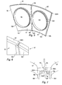
- the deflector 10 comprises a flat portion 10a with a central opening 10b corresponding to the housing of a not shown injector. On the figure 5 the opening is flanked by a flange 10b1 for fixing in the chamber bottom.
- the deflector comprises two longitudinal edges oriented in a radial direction relative to the axis of the motor: the longitudinal edge 10c and the edge 10d. They are straight.
- the deflector 10 also comprises two transverse edges 10e and 10f both rounded, to follow the curvature of the combustion chamber, and curved towards the interior of the combustion chamber for guiding the air.
- the edge 10c, left on the figure 5 is rectilinear and follows the radial profile of the deflector.
- the edge 10d on the other side comprises a rear recess with respect to the visible face on the figure 5 , 10d1 formed by a tongue which extends the rear face of the wall of the deflector.
- This recess forms a longitudinal housing 10d10 for the edge 10'c of the adjacent deflector 10 '.
- This deflector 10 ' is identical to the deflector 10. It comprises a flat portion 10'a, two longitudinal edges 10'c and 10'd and two transverse edges curved and curved 10'e and 10'f.
- the edge 10'd comprises a longitudinal tab 10'd1 providing a housing 10'd10.
- the baffles are all identical and are mounted on the periphery of the chamber bottom 16, not shown on the Figures 5 and 6 , being fixed by the flanges 10b1 and 10'b1, openings 10b, 10'b, for the injection systems.
- the joint cover formed by the tongue 10d1 of each of the baffles covers the edge 10'c adjacent deflector 10 'over a width sufficient to accommodate variations in expansion of the combustion chamber.
- Each housing 10d10, 10'd10 is arranged to retain the edge 10c, 10'c of the adjacent baffle such that leaks between two adjacent baffles are reduced or completely eliminated whatever the engine speed.
- the deflectors bear against the edge of the openings by a shoulder 10b1e and 10'b1e respectively.
- the wall of the baffle 10 extends along the edge 10d by the tongue 10d1 which covers the edge 10'c of the adjacent deflector 10 '. Thanks to the shoulder 10b1e 10'b1e a space is provided between the wall of the chamber bottom 16 and the rear faces of the baffles. Air in the form of a jet passes through the orifices 16a made in the wall of the chamber bottom between the two openings. It is noted that the deflectors are immobilized relative to the chamber bottom by clips 16b forming with the shoulders a clamp for the bottom wall of the chamber.
- the solution of the invention makes it possible at the same time to seal between the baffles and the air jet impact cooling in the narrow critical zone situated between the passage openings of the injection systems.
- the baffles are identical but the solution also includes the case where a first baffle 10 comprises a joint cover 10c1 and 10d1 along the two longitudinal edges cooperating with the simple edges 10'c and 10'd of a second deflector 10 'without joint cover.
- the effectiveness is the same.
- the editing is however different. It is simpler while requiring the manufacture of two parts references.
Abstract
Description
La présente invention se rapporte au domaine technique des chambres de combustion pour moteur à turbine à gaz. Elle vise en particulier le fond de chambre. Elle vise enfin un moteur à turbine à gaz tel qu'un turboréacteur équipé d'une telle chambre de combustion.The present invention relates to the technical field of combustion chambers for gas turbine engine. It is particularly aimed at the bedroom floor. Finally, it relates to a gas turbine engine such as a turbojet engine equipped with such a combustion chamber.
Dans tout ce qui suit, les termes « axial », « radial », « transversal » correspondent respectivement à une direction axiale, à une direction radiale, et à un plan transversal du moteur, et les termes « amont » et « aval » correspondent respectivement au sens de l'écoulement des gaz dans le moteur.In all that follows, the terms "axial", "radial", "transverse" correspond respectively to an axial direction, to a radial direction, and to a transverse plane of the engine, and the terms "upstream" and "downstream" correspond to respectively in the direction of the flow of gases in the engine.
Une chambre de combustion conventionnelle divergente est illustrée sur la
Cette chambre de combustion divergente 110 comporte deux parois concentriques : l'une externe 112 et l'autre interne 114, qui sont coaxiales et sensiblement coniques. Les parois s'évasent de l'amont vers l'aval. Les parois externe 112 et interne 114 de la chambre de combustion 110 sont reliées entre elles, vers l'amont de la chambre de combustion par un fond de chambre 116.This diverging
Le fond de chambre 116 est une pièce annulaire tronconique, qui s'étend entre deux plans sensiblement transversaux en s'évasant de l'aval vers l'amont. Le fond de chambre 116 se raccorde à chacune des deux parois externe 112 et interne 114 de la chambre de combustion 110. Le fond de chambre 116 présente une faible conicité. Il est doté de systèmes d'injection 118 à travers lesquelles passent des injecteurs 120 qui introduisent du carburant à l'extrémité amont de la chambre de combustion 110 où se déroulent les réactions de combustion.The
Ces réactions de combustion ont pour effet de faire rayonner de la chaleur de l'aval vers l'amont en direction du fond de chambre 116. Ainsi en fonctionnement le fond de chambre est-il soumis à de fortes températures. Afin de le protéger, des écrans thermiques sectorisés, encore appelés déflecteurs 122 sont interposés entre le foyer et les parois du fond de chambre. Ces déflecteurs 122, dont un est représenté sur la
Ce guidage le long des déflecteurs est assuré par les murets latéraux orientés radialement. Ces murets ont aussi une fonction d'étanchéité. En étant au contact ou en assurant un jeu minimal avec le fond de chambre, Ils empêchent l'air de venir s'immiscer entre deux déflecteurs adjacents, pénétrer dans le foyer et perturber la combustion. Ces perturbations ont une incidence sur la pollution et sont à éviter. En effet les performances en rejets de polluants, CO et CHx sont susceptibles d'être dégradées par l'introduction parasite de cet air froid particulièrement au régime de ralenti moteur où le jeu est plus important.This guidance along the baffles is provided by the side walls oriented radially. These walls also have a sealing function. By being in contact or by ensuring a minimum clearance with the chamber bottom, They prevent air from coming in between two adjacent baffles, enter the home and disrupt combustion. These disturbances affect pollution and should be avoided. Indeed, the pollutant discharge performance, CO and CHx are likely to be degraded by the parasitic introduction of this cold air particularly at engine idling speed where the game is more important.
L'évolution actuelle des moyens d'alimentation de la chambre en air et en carburant conduit à la réalisation de systèmes d'injection dont l'intégration dans le fond de chambre est plus difficile. Par exemple les systèmes d'injection de type multipoints sont de plus grand diamètre car une part importante de l'air admis dans la chambre les traverse ; ils occupent alors plus de place sur le pourtour du fond de chambre laissant un intervalle plus faible entre deux systèmes adjacents.The current evolution of the means for supplying the chamber with air and fuel leads to the production of injection systems whose integration into the chamber bottom is more difficult. For example, the multipoint type injection systems are larger in diameter because a large part of the air admitted into the chamber passes through them; they occupy more space around the bottom of the chamber leaving a smaller gap between two adjacent systems.
On retrouve une situation équivalente lorsqu'on est amené à augmenter le nombre de systèmes d'injection pour une même chambre dans le but de réduire les zones mortes entre deux injecteurs adjacents ou encore lorsque les dimensions du fond de chambre sont réduites pour un même nombre de système d'injection.An equivalent situation is found when it is necessary to increase the number of injection systems for the same chamber in order to reduce the dead zones between two adjacent injectors or when the dimensions of the chamber bottom are reduced for the same number. injection system.
Il s'ensuit dans ces cas que les ouvertures de centrage des déflecteurs sont proches les unes des autres. On dispose alors de peu de place pour aménager des murets latéraux sur les déflecteurs.It follows in these cases that the centering openings of the baffles are close to each other. There is little room for side walls on the baffles.
Les
Sur la
L'invention a pour objectif de remédier à ce problèmeThe object of the invention is to remedy this problem
Conformément à l'invention, la chambre de combustion annulaire de moteur à turbine à gaz comprenant une paroi externe, une paroi interne, une paroi reliant les deux parois et constituant un fond de chambre la paroi de fond de chambre étant pourvue d'ouvertures pour les systèmes d'injection de carburant, des déflecteurs de protection thermique étant fixés sur la paroi, les déflecteurs comprenant une portion de paroi plane avec une ouverture centrée sur lesdites ouvertures des systèmes d'injection de carburant, deux bords longitudinaux et deux bords transversaux, est caractérisée par le fait qu'au moins le long de l'un des bords longitudinaux un déflecteur comporte une languette, formant couvre joint, en ménageant un logement le long dudit bord pour le bord du déflecteur adjacent de façon à rendre étanche la jonction entre les deux bords, ladite languette étant espacée de la paroi du fond de chambre en ménageant un espace alimenté en air de refroidissement par des orifices sur la paroi de fond de chambre.According to the invention, the annular combustion chamber of a gas turbine engine comprising an outer wall, an inner wall, a wall connecting the two walls and constituting a chamber bottom, the chamber bottom wall being provided with openings for the fuel injection systems, thermal protection baffles being fixed to the wall, the baffles comprising a flat wall portion with an opening centered on said openings of the fuel injection systems, two longitudinal edges and two transverse edges, is characterized in that at least along one of the longitudinal edges a baffle comprises a tongue forming a seal, providing a recess along said edge for the edge of the adjacent deflector so as to seal the connection between the two edges, said tongue being spaced from the wall of the chamber bottom by providing a space supplied with cooling air by means of orifices on the bottom wall of the chamber.
Grâce à la solution de l'invention la zone critique située entre deux ouvertures adjacentes est à la fois étanche par le couvre joint et refroidie car le couvre joint permet l'agencement d'un espace alimenté en air de refroidissement.Thanks to the solution of the invention the critical zone located between two adjacent openings is both sealed by the joint cover and cooled because the joint cover allows the arrangement of a space supplied with cooling air.
Plus particulièrement la chambre présente les caractéristiques suivantes :
- Le logement est formé par un décrochement de la paroi ;
- Les déflecteurs comprennent un épaulement par lesquels ils s'appuient sur le bord des ouvertures des systèmes d'injection.
- The housing is formed by a recess of the wall;
- The baffles comprise a shoulder by which they rest on the edge of the openings of the injection systems.
L'épaulement ménage un jeu entre la paroi du fond de chambre et le couvre joint dans la zone comprise entre deux ouvertures adjacentes des systèmes d'injection de carburant.The shoulder provides clearance between the bottom wall of the chamber and the joint cover in the area between two adjacent openings of the fuel injection systems.
Les bords transversaux des déflecteurs comprennent une portion de paroi incurvée, les logements étant ménagés également le long des bords longitudinaux de ladite portion incurvée.The transverse edges of the deflectors comprise a curved wall portion, the housings being also formed along the longitudinal edges of said curved portion.
Les déflecteurs comprennent un couvre joint le long d'un bord longitudinal et un bord sans couvre joint le long de l'autre bord longitudinal les deux bords étant complémentaires pour venir s'adapter à un bord d'un autre même déflecteur disposé bord à bord.The baffles comprise a joint cover along a longitudinal edge and an edge without joint cover along the other longitudinal edge, the two edges being complementary to fit an edge of another same baffle disposed edge to edge .
Une partie des déflecteurs comprend un couvre joint le long des deux bords longitudinaux.Part of the baffles includes a seal cover along the two longitudinal edges.
Une partie des déflecteurs comprend deux bords longitudinaux complémentaires des couvre joints des déflecteurs précédents.Part of the deflectors comprises two complementary longitudinal edges of the joint covers of the previous deflectors.
D'autres caractéristiques et avantages ressortiront de la description qui suit de modes de réalisation de l'invention en référence aux dessins annexés sur lesquels
- La
figure 1 représente en coupe axiale une moitié de chambre de combustion de type divergent en soi connue ; - La
figure 2 montre un déflecteur de l'art antérieur utilisé pour la protection thermique de la paroi du fond de chambre de combustion ; - La
figure 3 montre une configuration de déflecteur selon l'enseignement de l'art antérieur ; - La
figure 4 montre une autre configuration selon l'enseignement de l'art antérieur ; - La
figure 5 montre, vus en perspective, deux déflecteurs de protection thermique du fond de chambre de l'invention; - La
figure 6 montre le détail du couvre joint sur les déflecteurs de lafigure 5 ; - La
figure 7 montre le détail de la zone sur la chambre de combustion entre deux ouvertures ; - La
figure 8 montre une variante de réalisation de l'étanchéité entre deux déflecteurs adjacents ;
- The
figure 1 represents in axial section a divergent type of combustion chamber of known per se; - The
figure 2 shows a deflector of the prior art used for thermal protection of the wall of the combustion chamber bottom; - The
figure 3 shows a deflector configuration according to the teachings of the prior art; - The
figure 4 shows another configuration according to the teaching of the prior art; - The
figure 5 shows, seen in perspective, two thermal protection baffles of the chamber bottom of the invention; - The
figure 6 shows the detail of the joint cover on the deflectors of thefigure 5 ; - The
figure 7 shows the detail of the area on the combustion chamber between two openings; - The
figure 8 shows an alternative embodiment of the seal between two adjacent deflectors;
On se reporte maintenant aux
Sur l'exemple des
On voit en coupe sur la
Ainsi la solution de l'invention permet à la fois d'assurer l'étanchéité entre les déflecteurs et le refroidissement par impact de jet d'air dans la zone critique, étroite, située entre les ouvertures de passage des systèmes d'injection.Thus, the solution of the invention makes it possible at the same time to seal between the baffles and the air jet impact cooling in the narrow critical zone situated between the passage openings of the injection systems.
Dans la réalisation des
Claims (9)
Applications Claiming Priority (1)
| Application Number | Priority Date | Filing Date | Title |
|---|---|---|---|
| FR0704828A FR2918443B1 (en) | 2007-07-04 | 2007-07-04 | COMBUSTION CHAMBER COMPRISING THERMAL PROTECTION DEFLECTORS OF BOTTOM BOTTOM AND GAS TURBINE ENGINE BEING EQUIPPED |
Publications (2)
| Publication Number | Publication Date |
|---|---|
| EP2012062A1 true EP2012062A1 (en) | 2009-01-07 |
| EP2012062B1 EP2012062B1 (en) | 2019-08-28 |
Family
ID=38982783
Family Applications (1)
| Application Number | Title | Priority Date | Filing Date |
|---|---|---|---|
| EP08159738.7A Active EP2012062B1 (en) | 2007-07-04 | 2008-07-04 | Combustion chamber comprising deflectors for thermal protection of the chamber dome and gas turbine engine equipped with same |
Country Status (6)
| Country | Link |
|---|---|
| US (1) | US8096134B2 (en) |
| EP (1) | EP2012062B1 (en) |
| JP (1) | JP5225769B2 (en) |
| CA (1) | CA2636661C (en) |
| FR (1) | FR2918443B1 (en) |
| RU (1) | RU2485404C2 (en) |
Cited By (3)
| Publication number | Priority date | Publication date | Assignee | Title |
|---|---|---|---|---|
| DE102011014670A1 (en) * | 2011-03-22 | 2012-09-27 | Rolls-Royce Deutschland Ltd & Co Kg | Segmented combustion chamber head |
| EP2012061B1 (en) * | 2007-07-05 | 2016-12-07 | Safran Aircraft Engines | Chamber dome deflector, combustion chamber comprising the same and gas turbine engine equipped with the same |
| FR3078384A1 (en) * | 2018-02-28 | 2019-08-30 | Safran Aircraft Engines | DOUBLE BOTTOM CHAMBER COMBUSTION CHAMBER |
Families Citing this family (10)
| Publication number | Priority date | Publication date | Assignee | Title |
|---|---|---|---|---|
| FR2910115B1 (en) * | 2006-12-19 | 2012-11-16 | Snecma | DEFLECTOR FOR BOTTOM OF COMBUSTION CHAMBER, COMBUSTION CHAMBER WHERE IT IS EQUIPPED AND TURBOREACTOR COMPRISING THEM |
| US9052116B2 (en) | 2008-10-30 | 2015-06-09 | Power Generation Technologies Development Fund, L.P. | Toroidal heat exchanger |
| CN102203388B (en) | 2008-10-30 | 2015-11-25 | 电力技术发展基金公司 | Toroidal boundary layer gas turbine |
| US8495881B2 (en) * | 2009-06-02 | 2013-07-30 | General Electric Company | System and method for thermal control in a cap of a gas turbine combustor |
| US9021812B2 (en) | 2012-07-27 | 2015-05-05 | Honeywell International Inc. | Combustor dome and heat-shield assembly |
| US10816201B2 (en) | 2013-09-13 | 2020-10-27 | Raytheon Technologies Corporation | Sealed combustor liner panel for a gas turbine engine |
| US10578021B2 (en) * | 2015-06-26 | 2020-03-03 | Delavan Inc | Combustion systems |
| FR3081974B1 (en) * | 2018-06-04 | 2020-06-19 | Safran Aircraft Engines | COMBUSTION CHAMBER OF A TURBOMACHINE |
| RU208130U1 (en) * | 2021-04-26 | 2021-12-06 | Публичное Акционерное Общество "Одк-Сатурн" | COMBUSTION CHAMBER FRONT WALL |
| CN115342382A (en) * | 2022-07-26 | 2022-11-15 | 清航空天(北京)科技有限公司 | Single-channel oxygen supply detonation combustion chamber module and detonation combustion chamber |
Citations (5)
| Publication number | Priority date | Publication date | Assignee | Title |
|---|---|---|---|---|
| US4380896A (en) * | 1980-09-22 | 1983-04-26 | The United States Of America As Represented By The Secretary Of The Army | Annular combustor having ceramic liner |
| US4843825A (en) * | 1988-05-16 | 1989-07-04 | United Technologies Corporation | Combustor dome heat shield |
| FR2637675A1 (en) * | 1988-10-12 | 1990-04-13 | United Technologies Corp | COMBUSTION CHAMBER FOR A TURBOMOTEUR |
| US6164074A (en) * | 1997-12-12 | 2000-12-26 | United Technologies Corporation | Combustor bulkhead with improved cooling and air recirculation zone |
| EP1118806A1 (en) * | 2000-01-20 | 2001-07-25 | Siemens Aktiengesellschaft | Thermally charged wall structure and method to seal gaps in such a structure |
Family Cites Families (27)
| Publication number | Priority date | Publication date | Assignee | Title |
|---|---|---|---|---|
| SU352573A1 (en) * | 1970-10-05 | 1983-06-23 | Pinchuk V V | Annular combustion chamber of gas turbine engine |
| US4180974A (en) * | 1977-10-31 | 1980-01-01 | General Electric Company | Combustor dome sleeve |
| US4567730A (en) * | 1983-10-03 | 1986-02-04 | General Electric Company | Shielded combustor |
| US5012645A (en) * | 1987-08-03 | 1991-05-07 | United Technologies Corporation | Combustor liner construction for gas turbine engine |
| SU1760254A1 (en) * | 1990-06-15 | 1992-09-07 | Уфимский Институт Им.Серго Орджоникидзе | Dust system |
| GB9018013D0 (en) * | 1990-08-16 | 1990-10-03 | Rolls Royce Plc | Gas turbine engine combustor |
| GB9018014D0 (en) * | 1990-08-16 | 1990-10-03 | Rolls Royce Plc | Gas turbine engine combustor |
| GB2257781B (en) * | 1991-04-30 | 1995-04-12 | Rolls Royce Plc | Combustion chamber assembly in a gas turbine engine |
| GB2287310B (en) * | 1994-03-01 | 1997-12-03 | Rolls Royce Plc | Gas turbine engine combustor heatshield |
| DE4427222A1 (en) * | 1994-08-01 | 1996-02-08 | Bmw Rolls Royce Gmbh | Heat shield for a gas turbine combustor |
| US5524438A (en) * | 1994-12-15 | 1996-06-11 | United Technologies Corporation | Segmented bulkhead liner for a gas turbine combustor |
| DE19508111A1 (en) * | 1995-03-08 | 1996-09-12 | Bmw Rolls Royce Gmbh | Heat shield arrangement for a gas turbine combustor |
| FR2751731B1 (en) * | 1996-07-25 | 1998-09-04 | Snecma | BOWL DEFLECTOR ASSEMBLY FOR A TURBOMACHINE COMBUSTION CHAMBER |
| US5974805A (en) * | 1997-10-28 | 1999-11-02 | Rolls-Royce Plc | Heat shielding for a turbine combustor |
| DE29815101U1 (en) * | 1998-08-22 | 2000-05-31 | Dimbath Wolfgang | Reusable case for a wind instrument |
| US6606861B2 (en) * | 2001-02-26 | 2003-08-19 | United Technologies Corporation | Low emissions combustor for a gas turbine engine |
| US6497105B1 (en) * | 2001-06-04 | 2002-12-24 | Pratt & Whitney Canada Corp. | Low cost combustor burner collar |
| US6952927B2 (en) * | 2003-05-29 | 2005-10-11 | General Electric Company | Multiport dome baffle |
| US7121095B2 (en) * | 2003-08-11 | 2006-10-17 | General Electric Company | Combustor dome assembly of a gas turbine engine having improved deflector plates |
| US7363763B2 (en) * | 2003-10-23 | 2008-04-29 | United Technologies Corporation | Combustor |
| US7673460B2 (en) * | 2005-06-07 | 2010-03-09 | Snecma | System of attaching an injection system to a turbojet combustion chamber base |
| FR2897144B1 (en) * | 2006-02-08 | 2008-05-02 | Snecma Sa | COMBUSTION CHAMBER FOR TURBOMACHINE WITH TANGENTIAL SLOTS |
| FR2897417A1 (en) * | 2006-02-10 | 2007-08-17 | Snecma Sa | ANNULAR COMBUSTION CHAMBER OF A TURBOMACHINE |
| FR2897922B1 (en) * | 2006-02-27 | 2008-10-10 | Snecma Sa | ARRANGEMENT FOR A TURBOREACTOR COMBUSTION CHAMBER |
| FR2903171B1 (en) * | 2006-06-29 | 2008-10-17 | Snecma Sa | CRABOT LINK ARRANGEMENT FOR TURBOMACHINE COMBUSTION CHAMBER |
| FR2909748B1 (en) * | 2006-12-07 | 2009-07-10 | Snecma Sa | BOTTOM BOTTOM, METHOD OF MAKING SAME, COMBUSTION CHAMBER COMPRISING SAME, AND TURBOJET ENGINE |
| FR2914399B1 (en) * | 2007-03-27 | 2009-10-02 | Snecma Sa | FURNITURE FOR BOTTOM OF COMBUSTION CHAMBER. |
-
2007
- 2007-07-04 FR FR0704828A patent/FR2918443B1/en active Active
-
2008
- 2008-07-03 JP JP2008174223A patent/JP5225769B2/en active Active
- 2008-07-03 US US12/167,542 patent/US8096134B2/en active Active
- 2008-07-03 RU RU2008127151/06A patent/RU2485404C2/en active
- 2008-07-04 CA CA2636661A patent/CA2636661C/en active Active
- 2008-07-04 EP EP08159738.7A patent/EP2012062B1/en active Active
Patent Citations (5)
| Publication number | Priority date | Publication date | Assignee | Title |
|---|---|---|---|---|
| US4380896A (en) * | 1980-09-22 | 1983-04-26 | The United States Of America As Represented By The Secretary Of The Army | Annular combustor having ceramic liner |
| US4843825A (en) * | 1988-05-16 | 1989-07-04 | United Technologies Corporation | Combustor dome heat shield |
| FR2637675A1 (en) * | 1988-10-12 | 1990-04-13 | United Technologies Corp | COMBUSTION CHAMBER FOR A TURBOMOTEUR |
| US6164074A (en) * | 1997-12-12 | 2000-12-26 | United Technologies Corporation | Combustor bulkhead with improved cooling and air recirculation zone |
| EP1118806A1 (en) * | 2000-01-20 | 2001-07-25 | Siemens Aktiengesellschaft | Thermally charged wall structure and method to seal gaps in such a structure |
Cited By (6)
| Publication number | Priority date | Publication date | Assignee | Title |
|---|---|---|---|---|
| EP2012061B1 (en) * | 2007-07-05 | 2016-12-07 | Safran Aircraft Engines | Chamber dome deflector, combustion chamber comprising the same and gas turbine engine equipped with the same |
| DE102011014670A1 (en) * | 2011-03-22 | 2012-09-27 | Rolls-Royce Deutschland Ltd & Co Kg | Segmented combustion chamber head |
| US9328926B2 (en) | 2011-03-22 | 2016-05-03 | Rolls-Royce Deutschland Ltd & Co Kg | Segmented combustion chamber head |
| FR3078384A1 (en) * | 2018-02-28 | 2019-08-30 | Safran Aircraft Engines | DOUBLE BOTTOM CHAMBER COMBUSTION CHAMBER |
| WO2019166745A1 (en) * | 2018-02-28 | 2019-09-06 | Safran Aircraft Engines | Combustion chamber having a double chamber bottom |
| US11248793B2 (en) | 2018-02-28 | 2022-02-15 | Safran Aircraft Engines | Combustion chamber having a double chamber bottom |
Also Published As
| Publication number | Publication date |
|---|---|
| US8096134B2 (en) | 2012-01-17 |
| EP2012062B1 (en) | 2019-08-28 |
| RU2485404C2 (en) | 2013-06-20 |
| JP2009014337A (en) | 2009-01-22 |
| US20090013694A1 (en) | 2009-01-15 |
| CA2636661A1 (en) | 2009-01-04 |
| FR2918443B1 (en) | 2009-10-30 |
| JP5225769B2 (en) | 2013-07-03 |
| CA2636661C (en) | 2015-11-24 |
| FR2918443A1 (en) | 2009-01-09 |
| RU2008127151A (en) | 2010-01-10 |
Similar Documents
| Publication | Publication Date | Title |
|---|---|---|
| EP2012062B1 (en) | Combustion chamber comprising deflectors for thermal protection of the chamber dome and gas turbine engine equipped with same | |
| EP2012061B1 (en) | Chamber dome deflector, combustion chamber comprising the same and gas turbine engine equipped with the same | |
| EP2334909B1 (en) | Sealing between a combustion chamber and a turbine distributor in a turbine engine | |
| CA2469849C (en) | Combustion chamber having a flexible liaison between the chamber floor and chamber wall | |
| CA2727254C (en) | Gas turbine engine combustion chamber comprising cmc deflectors | |
| EP1898155B1 (en) | Annular combustion chamber of a turbomachine | |
| FR2752916A1 (en) | THERMAL PROTECTIVE SHIRT FOR TURBOREACTOR COMBUSTION CHAMBER | |
| FR2935465A1 (en) | Combustion chamber for gas turbine engine, has casing that is in support on upstream face of chamber bottom wall, where casing carries deflector support constituting stop arranged in manner to maintain deflector in contact with wall | |
| EP2638275A1 (en) | Gas distribution manifold and corresponding gas intake module | |
| EP3569929A1 (en) | Assembly for a turbine engine combustion chamber | |
| EP2040001B1 (en) | Annular combustion chamber for a gas turbine engine | |
| FR2998038A1 (en) | COMBUSTION CHAMBER FOR A TURBOMACHINE | |
| EP1930659A1 (en) | Jet engine combustion chamber | |
| EP1950497B1 (en) | Diffusion chamber for gas turbine engine, combustion chamber and gas turbine engine comprising same | |
| EP1939528B1 (en) | Deflector for the bottom of a combustion chamber, combustion chamber equipped with same and jet engine comprising them | |
| WO2009144408A2 (en) | Annular combustion chamber for gas turbine engine | |
| EP3928034B1 (en) | Combustion chamber for a turbomachine | |
| EP2469066B1 (en) | Manifold for distributing gas in the intake ducts of a heat engine of an automobile and intake module provided with such a manifold | |
| FR2875266A1 (en) | Twin scroll type exhaust manifold for e.g. 1342 type four-cylinder engine, has outlet conduit with partition in rectangular plate form inserted into guide with lateral expansion gap, where plate is made of austenitic stainless steel sheet | |
| FR2886338A1 (en) | I.c. engine double-walled exhaust manifold has inner liner separated from outer wall in flange zones by insulating plugs | |
| EP3976947B1 (en) | Notch on a cylinder head inlet surface for oblique attachment on an engine cylinder head | |
| EP0950859A1 (en) | Separator for combustion chamber with two burner heads | |
| WO2024028551A1 (en) | Exhaust system for a turbine engine, comprising a heat exchanger | |
| FR3094783A1 (en) | Diagonal fixing device on cylinder head | |
| FR3085743A1 (en) | ANNULAR COMBUSTION CHAMBER FOR A TURBOMACHINE |
Legal Events
| Date | Code | Title | Description |
|---|---|---|---|
| PUAI | Public reference made under article 153(3) epc to a published international application that has entered the european phase |
Free format text: ORIGINAL CODE: 0009012 |
|
| 17P | Request for examination filed |
Effective date: 20080704 |
|
| AK | Designated contracting states |
Kind code of ref document: A1 Designated state(s): AT BE BG CH CY CZ DE DK EE ES FI FR GB GR HR HU IE IS IT LI LT LU LV MC MT NL NO PL PT RO SE SI SK TR |
|
| AX | Request for extension of the european patent |
Extension state: AL BA MK RS |
|
| AKX | Designation fees paid |
Designated state(s): DE FR GB IT |
|
| 17Q | First examination report despatched |
Effective date: 20090814 |
|
| RAP1 | Party data changed (applicant data changed or rights of an application transferred) |
Owner name: SNECMA |
|
| RAP1 | Party data changed (applicant data changed or rights of an application transferred) |
Owner name: SAFRAN AIRCRAFT ENGINES |
|
| GRAP | Despatch of communication of intention to grant a patent |
Free format text: ORIGINAL CODE: EPIDOSNIGR1 |
|
| INTG | Intention to grant announced |
Effective date: 20190212 |
|
| GRAS | Grant fee paid |
Free format text: ORIGINAL CODE: EPIDOSNIGR3 |
|
| GRAA | (expected) grant |
Free format text: ORIGINAL CODE: 0009210 |
|
| AK | Designated contracting states |
Kind code of ref document: B1 Designated state(s): DE FR GB IT |
|
| REG | Reference to a national code |
Ref country code: GB Ref legal event code: FG4D Free format text: NOT ENGLISH |
|
| REG | Reference to a national code |
Ref country code: DE Ref legal event code: R096 Ref document number: 602008061023 Country of ref document: DE |
|
| REG | Reference to a national code |
Ref country code: DE Ref legal event code: R097 Ref document number: 602008061023 Country of ref document: DE |
|
| PLBE | No opposition filed within time limit |
Free format text: ORIGINAL CODE: 0009261 |
|
| STAA | Information on the status of an ep patent application or granted ep patent |
Free format text: STATUS: NO OPPOSITION FILED WITHIN TIME LIMIT |
|
| 26N | No opposition filed |
Effective date: 20200603 |
|
| PGFP | Annual fee paid to national office [announced via postgrant information from national office to epo] |
Ref country code: IT Payment date: 20230620 Year of fee payment: 16 Ref country code: FR Payment date: 20230621 Year of fee payment: 16 |
|
| PGFP | Annual fee paid to national office [announced via postgrant information from national office to epo] |
Ref country code: GB Payment date: 20230620 Year of fee payment: 16 |
|
| PGFP | Annual fee paid to national office [announced via postgrant information from national office to epo] |
Ref country code: DE Payment date: 20230620 Year of fee payment: 16 |