EP1974655A1 - Method, device and arrangement for measuring dynamic behaviour of an optical system - Google Patents
Method, device and arrangement for measuring dynamic behaviour of an optical system Download PDFInfo
- Publication number
- EP1974655A1 EP1974655A1 EP08012683A EP08012683A EP1974655A1 EP 1974655 A1 EP1974655 A1 EP 1974655A1 EP 08012683 A EP08012683 A EP 08012683A EP 08012683 A EP08012683 A EP 08012683A EP 1974655 A1 EP1974655 A1 EP 1974655A1
- Authority
- EP
- European Patent Office
- Prior art keywords
- eye
- aberrometer
- optical system
- stimulation unit
- dynamic
- Prior art date
- Legal status (The legal status is an assumption and is not a legal conclusion. Google has not performed a legal analysis and makes no representation as to the accuracy of the status listed.)
- Granted
Links
Images

Classifications
-
- A—HUMAN NECESSITIES
- A61—MEDICAL OR VETERINARY SCIENCE; HYGIENE
- A61B—DIAGNOSIS; SURGERY; IDENTIFICATION
- A61B3/00—Apparatus for testing the eyes; Instruments for examining the eyes
- A61B3/10—Objective types, i.e. instruments for examining the eyes independent of the patients' perceptions or reactions
- A61B3/1015—Objective types, i.e. instruments for examining the eyes independent of the patients' perceptions or reactions for wavefront analysis
-
- A—HUMAN NECESSITIES
- A61—MEDICAL OR VETERINARY SCIENCE; HYGIENE
- A61B—DIAGNOSIS; SURGERY; IDENTIFICATION
- A61B3/00—Apparatus for testing the eyes; Instruments for examining the eyes
- A61B3/10—Objective types, i.e. instruments for examining the eyes independent of the patients' perceptions or reactions
- A61B3/103—Objective types, i.e. instruments for examining the eyes independent of the patients' perceptions or reactions for determining refraction, e.g. refractometers, skiascopes
Definitions
- the invention relates to a method, a device and an arrangement for measuring the dynamic behavior of an optical system.
- z. B adaptive optics that act as deformable mirrors in reflection or liquid crystal optics that work in transmission.
- These adaptive optics are technologically complex and z. Z. not yet mature in all its consequences.
- You reach z. Z. areal Resolutions of typically a few square millimeters and are already being used under laboratory conditions to influence wavefronts in feedback processes between wavefront measurement and adaptive element (see Fernandez, EJ Iglesias, I., Artal, P. "Closed Loop Adaptive Optics in the Human Eye", Optics Letters, Vol.
- This problem is solved by a method for measuring the dynamic behavior of an optical system, in which the optical system to be measured is stimulated by stimuli to a reaction and the reaction is detected by means of wavefront analysis.
- the dynamic behavior of the optical system are, in particular, adaptation processes to changed visual conditions, for example an accommodation or an aperture adjustment (adaptation).
- the optical system may be an eye, for example a human eye, an artificial eye or any artificial device.
- the stimulus can basically be of any nature.
- the reaction is the dynamic behavior of the optical system following the stimulus.
- the wavefront analysis can be carried out, for example, with an aberrometer, in particular by means of Shack / Hartmann sensors, but also with aberrometers according to the Cherning principle, according to Abbe, with a ray tracing aberrometer or system according to the Siaskop principle.
- the respective current focus of the optical system and its time course can be detected.
- different aperture settings can be recorded with respect to their time course.
- the dynamic behavior can be examined, for example, under the influence of drugs.
- the stimuli are optical and / or mechanical and / or electrical and / or chemical stimuli.
- Variable optical stimuli can be effected, for example, in the form of active controllable light sources, illuminated displays or the like.
- the image sharpness and / or the object distance and / or its focus and / or the intensity of the optical stimulus can be changed so that an accommodation or an aperture adjustment (adaptation) of the optical system can be provoked.
- an aberration of higher order for example in the form of a correspondingly "deformed" object wavefront, can also be used as the optical stimulus.
- Variable mechanical stimuli can be generated, for example, as a draft by a blower.
- Variable chemical stimuli can be achieved, for example, by smoke or the introduction of a liquid, a gas or an aerosol. Also, the administration as a drug is possible.
- Variable electrical stimuli are possible directly by electrodes applied to the eye or in the region of the eye or by inductive or capacitive coupling of an electrical signal. The said stimuli can each be combined individually or in any desired manner be applied and changed both abruptly and continuously.
- the optical system to be measured is a human eye.
- the method aims at inducing a targeted excitation and thus influencing the eye parameters when stimulating the individual eye or the eye system in the visual process.
- the changes in the eye parameters associated with the influences directly change the imaging properties of the eye and are therefore accessible, for example, by a synchronous to the excitation triggered wavefront measurement.
- a wide variety of effects can be examined and measured. For example, the time dependence and speed of the accommodation and the accommodative ability, the adaptation and adaptability or speed of the eye under influences such. As aberration, lighting, medication or psychological influences are examined.
- the dynamic short and long term behavior of contact lenses can be examined for changes in aberration by wearing contact lenses.
- the dynamic behavior of intraocular lenses (IOL), accommodative intraocular lenses and the interaction of the residual ciliary body with intraocular lenses, as well as their fit and movement and possibly induced accommodation, can be assessed.
- IOL intraocular lenses
- accommodative intraocular lenses and the interaction of the residual ciliary body with intraocular lenses, as well as their fit and movement and possibly induced accommodation can be assessed.
- there are connections between physical vision and brain power which may be related to It may be possible to uncover objective findings on clinical pictures such as headaches caused by overexertion. For example, glare and other time-varying impressions associated with fatigue during driving can be measured.
- the optical dynamic correction can, for example, be examined in relation to the occupational group, that is to say for certain requirements of the eyesight.
- the stimulation of the eye to be measured is synchronized with the aberrometer.
- the synchronization may be e.g. time or with respect to the intensity between the respective stimulus and the measurement of aberrometry
- one or both human eyes may be stimulated to react, as well as one or both human eyes may be measured. Based on the obtained stimulated, dynamic measurement results, optimized / averaged values for the static / stationary correction of the wavefront can be derived for the respective measured special eye. This can provide the eye with an optimal wavefront correction for its special action spectrum.
- special solutions can be provided for special visual operations. Examples include night vision, speed-optimized accommodation or television or television.
- a device for measuring the dynamic behavior of an optical system comprising a stimulation unit and an aberrometer.
- the stimulation unit can be used to initiate targeted adaptation processes to external stimuli of the optical system to be examined.
- the stimulation unit is designed so that it can exert external stimuli on the optical system. In principle, all physical or chemical effects or agents which cause an adaptation reaction of the optical system come into consideration as external stimuli.
- the stimulation unit can act abruptly and / or continuously on the optical system and which may be located either in front of the unmeasured optical system or the optical system to be measured.
- an aberrometer here are generally understood devices for wavefront measurement or for measuring the aberration. These may be both electronic data collection devices and manually operated devices.
- the aberrometer comprises a device for wavefront analysis.
- the device for wavefront analysis can z.
- the measurement results and thus the result of the dynamic adaptation process can be graphically visualized by means of data transfer into a software application.
- the stimulation unit can trigger an optical and / or mechanical and / or electrical and / or chemical stimulus.
- an optical stimulus can be designed so that an accommodation or aperture presentation of the optical system is provoked. In this way, different stimuli can be exercised on the eye and so also everyday situations such. As draft or induced by smoke chemical stimuli or the like can be simulated.
- the stimulation unit can be arranged in front of the eye looking past the aberrometer; alternatively, for example, the beam path of the stimulation unit can be mirrored into the aberrometer.
- the eye not to be examined can be stimulated by stimuli; in the second-mentioned embodiment of the device, the eye to be examined can be directly stimulated by external stimuli.
- the stimulation unit may be integrated into the aberrometer.
- the beam path of the stimulation unit is coupled directly into that of the aberrometer in a common housing. This allows a very compact design.
- the device can be designed for both monocular and binocular vision.
- stimulation may affect one or both eyes. Therefore, any combination of measuring one eye and stimulating one eye can be realized, for example stimulation of one eye and measurement of the other eye, stimulation of an eye and measurement of the same eye, stimulation of one eye and measurement of both eyes, stimulation of both eyes and measurement of one eye Eye or both eyes.
- the stimulation unit comprises a fixation object.
- the fixation object is a visual representation or a defined light spot easily recognizable by the subject. Preference is given here to a finely structured image or one composed of a plurality of elements, which may be graduated in color, for example, a composite light source.
- the fixation object can deliver a light stimulus that is variable in its intensity and / or focus.
- the eye that focuses the fixation object can thus be directly stimulated.
- the change in intensity can be achieved, for example, by a change in the luminous intensity in the case of light sources as active elements or by a change in the illuminance in the case of passive elements such as an illuminated graphic.
- a change of focus is, for example, by the method of Fixation object itself or by a change in upstream lenses possible.
- the fixation object is preferably a lighted graphic. It is an object that can be easily and safely recognized and fixed by the subject and is also easy to implement.
- the device may comprise at least one phase plate which can be introduced into the beam path of the stimulation unit and / or the aberrometer.
- a set of phase plates is used, which are sorted according to the different Zernike polynomials with graduated amplitudes and which can be positioned in the known phoropter in front of the system under investigation similar to trial lenses.
- a phase plates for example, transparent glass or plastic plates can be used, the surface of which is structured so that a continuous light wave defined aberrations are impressed, for example, a single Zernike term accordingly.
- plates of an order of the Zernike coefficients having different amplitudes are preferably arranged.
- the device may include software for evaluating the differently stimulated dynamic measurement data of the eye, which provides an optimal or averaged value of the wavefront used for the static / stationary correction of optical vision defects in the known correction methods (spectacles, CL, IOL, LASIK, PRK, ...) is used.
- the problem mentioned at the outset is also solved by an arrangement for measuring the dynamic behavior of an optical system, preferably an eye, comprising an aberrometer and a stimulation unit.
- an arrangement for measuring the dynamic behavior of an optical system preferably an eye, comprising an aberrometer and a stimulation unit.
- a separation of the previously realized together in the context of the device elements is made. It is therefore also possible to use a conventional device for measuring the aberration of an eye with a stand-alone stimulation unit.
- the problem mentioned at the outset is also solved by the use of a device according to one of the claims directed to a device for measuring the dynamic behavior of an optical system.
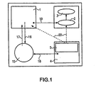
- Fig. 1 Referenced This shows the schematic diagram of a device and the associated procedure for the dynamic stimulation and dynamic measurement of the aberrometry of an eye 15. Shown are the individual components in their effect context.
- the device comprises a Device for wavefront measurement / aberrometry of the eye 15, in which either both eyes can be measured simultaneously or one eye at a time. In the last-mentioned case, the eye that has just not been measured may, if appropriate, look past the device or look into the device as well.
- the device for wavefront measurement / aberrometry of an eye will be referred to below as aberrometer 1. From the aberrometer 1 measuring light 16 is irradiated into the eye 15, which emits signal light 17.
- the device further comprises a device for dynamic data acquisition 2, which receives raw data 19 of the aberrometer 1.
- These can be conventional electronic devices for measured value acquisition.
- This device can be, for example, a program-controlled computer with software that can in particular acquire sequential measurement series in real time. Optionally, this is a data buffering in a volatile or non-volatile memory z.
- the apparatus further includes analysis software that can analyze the acquired data or data sets to calculate the wavefront determinants (eg, Zernike, Taylor coefficients). The measurement results and thus the result of the dynamic adaptation process can be graphically visualized by means of a software application.
- an analysis module 3 to which the determined data is transferred.
- the capabilities of the dynamic data acquisition 2 and of the analysis module 3 can be combined in such a way that a sequential real-time measurement with simultaneous analysis adapted to the hardware and optionally reduced in the acquisition rate can take place.
- a stimulation unit 4 for abrupt and / or continuously variable optical action such as aberration, light influence, object distance or the like is present, which either before the unmeasured eye 15 or the is arranged to be measured eye 15 and which may be synchronized with the dynamic data acquisition 2.
- the stimulation of the eye 15 is in Fig. 1 indicated by an arrow 18
- a synchronization unit 5 is used for synchronization between stimulation unit 4 and aberrometer 1.
- the synchronization unit can synchronizing pulses 20, in Fig. 1 indicated by dashed arrows, deliver to the aberrometer and / or the device for dynamic data acquisition 2.
- the stimulation of the eye can also be done on visual charts and the like, with a synchronization need not be present. This then eliminates the connection between the stimulation unit 4 and the aberrometer 1 and / or the dynamic data acquisition 2.
- Aberrometer 1, dynamic data acquisition 2, analysis module 3 and stimulation unit 4 can also be implemented as a unit and thus one-piece assembly.
- the stimulation unit 4 can also be realized and used as an independent, separate device.
- the then present device is a kind of stimulation phoropter, by the subject z. B. can assess a phase plate correction with or without variation of other visual parameters.
- the synchronization unit 5 can then be omitted.
- FIGS. 2 and 3 show embodiments of the device.
- the illustrated beam paths through a first lens 6, a second lens 7 and a third lens 8 do not correspond exactly to the real beam progressions when viewed in the context of geometric optics, but are only intended to illustrate.
- the concrete realization of the optical concept can be done so that the nose of the patient is not an obstacle.
- the optical setup is shown as having a phase plate 9 in a plane conjugate to the corneal surface or spectacle correcting surface.
- further target devices may be provided, eg area crosses.
- the centering can also be controlled by a video image that is inside the device FIGS. 2 and 3 can be tapped for example by beam splitter.
- Varying accommodation states may be stimulated by moving the fixation object along a travel path 13 or alternatively, for example, the third lens 8.
- the adaptation can be influenced by adjusting the illumination of the fixation object 12 by a light source 14. Additionally or alternatively, a direct adjustment of the brightness of the room light and / or the ambient light can take place. This possibility is not shown for the sake of simplicity.
- the individual components can be driven and driven electrically or by electric motor. The synchronization of these components with the measurement and akquir réelle can then z. B. conveniently done via the query programmable interfaces.
- the device comprises an aberrometer 1, it is a device for measuring the wavefront deformation by the optical system of the eye and thus for determining and classifying the aberrations of the eye 15, while also aberrations higher order is included.
- the aberrometer 1 is coupled with a Device for dynamic data acquisition 2. This is a module for controlling the aberrometer 1. This module can trigger a wavefront measurement process. Likewise, the measured data obtained can be temporarily stored and then the measured wavefront can be reconstructed from the measured data.
- the raw data of the video image of the sensor or completely evaluated wavefront parameters such as Zernike coefficients can be stored. Measurement and eventual evaluation and storage take place at clock rates which are faster than the adaptation process to be investigated.
- the clock rates may be in the range of 10 to 100 Hz, for example.
- the device for dynamic data acquisition 2 is coupled to an analysis module 3.
- the analysis module 3 is used to evaluate the sensor data and possibly the reconstruction and graphic visualization of the measured and stored wavefronts and is largely feasible in software. Furthermore, a parameterization of the wavefront z. B. by development according to Zernike polynomials or by zonal reconstruction are performed.
- the analysis process may be coupled in close association with the dynamic data acquisition device 2 and may perform the analysis process partially or completely before caching.
- a stimulation unit 4 consists essentially of an optical system which presents to the eye 15 to be examined or to be fixed a detailed structured visual object and moves the eye 15 to focus on the structure of the object.
- the stimulation unit 4 may optical elements such. B. have lenses or phase plates that deform the emanating from the visual object wavefront before they get into the eye 15. This allows the eye 15 to strive to obtain a clear image of the subject of vision obtained to be stimulated to adaptation reactions within the optical system.
- the imaging properties of the stimulation unit 4 can be varied over time to produce a dynamic response of the eye 15.
- the stimulation unit 4 can send information about its current state to a synchronization unit 5 with the wavefront measurement.
- the synchronization unit 5 is a module for the synchronization of dynamic changes in the stimulation unit 4 with the device for dynamic data acquisition 2.
- the aim is to correlate the measured wavefront data with the respective states of the synchronization unit.
- FIGS. 2 and 3 illustrated solutions of an aberrometer 1 can be referred to as dynamic stimulation aberroscopes.
- the optical concept can be made in such a way that the unmeasured eye does not have to be restricted in its view as shown, but can look free.
- the synchronization between the stimulation unit 4 and aberrometer 1 and the device for dynamic data acquisition 2 could be dispensed with.
- Other variants use for stimulation instead of an integrated fixation object z.
- a stimulation unit 4 can also be seen as an improvement to simple Phasenplattenphoropter and can in the various variants z. B. be designed with a correction of the aberration and a simple eye chart as fixation object, etc. as a standalone device.
- an adaptive optical element can be introduced.
- the thereby stimulated dynamic changes of the imaging properties of the eye 15 are dynamically detected by the aberrometer 1 in a temporal sequence which can be synchronized with the variation of the imaging properties by the adaptive optics.
- Transmission-based adaptive elements such. B. liquid crystal phase modulators z. B. instead of the phase plate in a similar manner in the arrangement according to the FIGS. 2 and 3 to be built in.
- any aberrations of the object wavefront can be changed dynamically or applied in a targeted manner.
- the stimulation unit 4 is designed as an optical system, which is either placed in front of the freely passing eye 15 or is reflected in the beam path of the aberrometer examined eye, as shown in Fig. 3 is shown, or the stimulation unit 4 is integrated into the aberrometer 1. Again, in this last embodiment, two variants are possible, the stimulation unit can act on the one or more measured eyes 15 or the stimulation unit 4 can act on the unmeasured eye 15.
- the stimulation unit itself is an optical device, in which a fixation object in front of the measured or unmeasured or free-looking eyes and at the center of which the respective eye is to look and focus during the examination.
- the optical effect in the stimulation can be modulated either abruptly or continuously, which z. B. by changing the distance, luminance, etc. of the fixation object can be achieved and / or by attaching phase plates. All optically effective modifications can be combined as desired. If the optical effect is synchronized with the dynamic measurement of the eye 15 by the aberrometer 1 z. B. in the sense of a time synchronization or a lighting synchronization, we obtain embodiments of the devices according to the FIGS. 2 and 3 , The effect does not necessarily have to be synchronized.
- Information about the dynamic reactions of the eye or the eyes can also be measured unsynchronized. This can z. B. on the knowledge of akquir michsfrequenz the device for dynamic data acquisition 2, a temporal assignment of the measured values are made, these can be provided for example with an electronic storage on a data carrier or the like with a time stamp.
- the dynamic data acquisition device 2 and the analysis module 3 can also be combined in such a way that not only dynamic data acquisition but simultaneously high-speed analysis of the data takes place.
- the fixation object 12 may, for. B. be realized by a lighted graphics with sufficiently fine structuring, but can also be a simple, separately positioned vision chart.
- the image of the fixation object 12 can be achieved by swiveling in optical elements such as lenses and optionally controlled by a video system.
- the centering on a given direction of view can be optimized by glare systems.
- An automatic positioning z. B. allowed by varying distances to cause specific accommodation conditions between the optical components and / or the fixation object.
- a suitable illumination setting of the fixation object and / or the room light leads to defined adaptation settings, which can also be kept variable and form additional measurement parameters.
- the device By introducing specially prepared phase plates with a defined surface topography in the beam path of the stimulation unit 4 and / or the aberrometer 1, the device allows the targeted application of aberrations on the eyes or the eyes 15.
- the phase plates can be arranged in a change turret not shown here and individually or be introduced in combination in the beam path of the stimulation unit 4 and / or the aberrometer 1.
- the device shown above and the method that can be carried out serve the targeted visual stimulation of a biological or artificial eye 15 and for detecting the associated dynamic adjustment process of the optical visual system by measuring the wavefront aberration.
- the visual stimulation which is produced when looking into or through a suitable apparatus, leads to an influence on the imaging properties of the eye 15, which can be measured simultaneously in real time with a wavefront analysis system or an aberrometer 1 synchronized with the stimulation.
- This allows completely new diagnostic options, which makes the dynamics of adaptation processes of the eye 15 accessible. For this purpose, visual conditions such as object distance and brightness are modified and, in particular, specific aberrations are specifically corrected and / or introduced at the same time. This can z.
- an implantable intraocular lens is accommodative by virtue of the residual ciliary body and how that could possibly be optimally used.
- An advantage of the invention is also to be able to correlate subjective impressions in the evaluation of dynamic visual processes by a subject with physically objective measurement data.
- the described invention offers the possibility of objectively dynamic measurement of the imaging properties of the eye with specifically stimulated adaptation processes under predetermined boundary conditions.
Landscapes
- Life Sciences & Earth Sciences (AREA)
- Health & Medical Sciences (AREA)
- Medical Informatics (AREA)
- Biophysics (AREA)
- Ophthalmology & Optometry (AREA)
- Engineering & Computer Science (AREA)
- Biomedical Technology (AREA)
- Heart & Thoracic Surgery (AREA)
- Physics & Mathematics (AREA)
- Molecular Biology (AREA)
- Surgery (AREA)
- Animal Behavior & Ethology (AREA)
- General Health & Medical Sciences (AREA)
- Public Health (AREA)
- Veterinary Medicine (AREA)
- Eye Examination Apparatus (AREA)
- Testing Of Optical Devices Or Fibers (AREA)
- Heat Treatment Of Steel (AREA)
- Investigating, Analyzing Materials By Fluorescence Or Luminescence (AREA)
Abstract
Description
Die Erfindung betrifft ein Verfahren, eine Vorrichtung und eine Anordnung zur Messung des dynamischen Verhaltens eines optischen Systems.The invention relates to a method, a device and an arrangement for measuring the dynamic behavior of an optical system.
Die Analyse optischer Wellenfronten von abbildenden Systemen und Lasersystemen hat eine zunehmende Bedeutung erlangt, da dies Ausgangspunkt für die Qualitätssteigerung dieser Systeme ist. Mit der Verfügbarkeit kommerzieller Shack-Hartmann-Sensoren (z. B. SCLA-series, WavefrontSciences, http://wavefrontsciences.com) kann man Aberrationen sehr genau erfassen und in Form von Zernike-Polynomen verschiedener Ordnungen oder alternativer Darstellungen klassifizieren.The analysis of optical wavefronts of imaging systems and laser systems has become increasingly important, since this is the starting point for improving the quality of these systems. With the availability of commercial Shack-Hartmann sensors (eg, SCLA-series, WavefrontSciences, http://wavefrontsciences.com), aberrations can be detected very accurately and classified as Zernike polynomials of different orders or alternative representations.
Auch andere Aberrometer nach dem Tscherning-Prinzip, nach Abbe oder das Tracey-Aberrometer (ray-tracing) oder Systeme nach dem Skiaskop-Prinzip erlauben die Erfassung der höheren Aberrationen.Other aberrometers based on the Cherning principle, Abbe or the Tracey aberrometer (ray tracing) or systems based on the skiascope principle also allow detection of the higher aberrations.
Systeme wie z. B. Shack-Hartmann-Sensoren, die mit einem CCD-Chip zur Speicherung der optisch relevanten Information ausgestattet sind, ermöglichen eine Datenakquirierung mit Videobildfrequenzen vorzunehmen und deshalb dynamische Abläufe ausreichend schnell aufzuzeichnen.Systems such. B. Shack-Hartmann sensors, which are equipped with a CCD chip for storing the optically relevant information, allow Datenakquirierung make with video image frequencies and therefore record dynamic processes sufficiently quickly.
Bekannt sind Methoden, über die normale sphärische und zylindrische Korrektur der Abbildungsfehler hinausgehend, auch die höheren Aberrationen ab dritter Ordnung gemäß Seidel bzw. Zernike-Klassifizierung zu korrigieren. Dazu verwendet man z. B. adaptive Optiken, die als deformierbare Spiegel in Reflexion wirken oder Flüssigkristalloptiken, die in Transmission arbeiten. Diese adaptiven Optiken sind technologisch aufwendig und z. Z. noch nicht in allen Konsequenzen ausgereift. Sie erreichen z. Z. flächenhafte Auflösungen von typischerweise einigen Quadratmillimetern und werden bereits unter Laborbedingungen eingesetzt, um Wellenfronten in Rückkopplungsverfahren zwischen Wellenfrontmessung und adaptivem Element zu beeinflussen (siehe dazu
Des Weiteren wurden insbesondere für ophtalmologische Anwendungen Methoden aufgezeigt, durch das optische System des Auges deformierte Wellenfronten auf einen Idealwert hin zu korrigieren, indem Aberrationen höherer Ordnung integral berücksichtigt werden (siehe dazu
Furthermore, especially for ophthalmological applications, methods were shown to correct distorted wavefronts to an ideal value by integrating aberrations of higher order integrally (see
Es ist daher Aufgabe der vorliegenden Erfindung, ein Verfahren, eine Vorrichtung sowie eine Anordnung bereitzustellen, mit denen das dynamische Verhalten eines optischen Systems objektiv erfassbar ist.It is therefore an object of the present invention to provide a method, a device and an arrangement with which the dynamic behavior of an optical system can be detected objectively.
Dieses Problem wird durch ein Verfahren zur Messung des dynamischen Verhaltens eines optischen Systems gelöst, bei dem das zu messende optische System durch Reize zu einer Reaktion stimuliert wird und die Reaktion mittels einer Wellenfrontanalyse erfasst wird.This problem is solved by a method for measuring the dynamic behavior of an optical system, in which the optical system to be measured is stimulated by stimuli to a reaction and the reaction is detected by means of wavefront analysis.
Das dynamische Verhalten des optischen Systems sind insbesondere Anpassungsvorgänge an veränderte Sehbedingungen, beispielsweise eine Akkomodation oder eine Blendenverstellung (Adaption). Das optische System kann ein Auge, beispielsweise ein menschliches Auge, ein künstliches Auge oder eine beliebige, künstliche Vorrichtung sein. Der Reiz kann grundsätzlich beliebiger Natur sein. Die Reaktion ist das dem Reiz nachfolgende dynamische Verhalten des optischen Systems. Die Wellenfrontanalyse kann beispielsweise mit einem Aberrometer, insbesondere mittels Shack-/Hartmann-Sensoren, aber auch mit Aberrometern nach dem Tscherning-Prinzip, nach Abbe, mit einem Ray-Tracing-Aberrometer oder System nach dem Siaskop-Prinzip durchgeführt werden. Bei der Akkomodation kann insbesondere der jeweils aktuelle Fokus des optischen Systems und dessen zeitlicher Verlauf erfasst werden. Ebenso können unterschiedliche Blendeneinstellungen bezüglich Ihres zeitlichen Verlaufs erfasst werden. Das dynamische Verhalten kann dabei beispielsweise auch unter Einfluß von Medikamenten untersucht werden.The dynamic behavior of the optical system are, in particular, adaptation processes to changed visual conditions, for example an accommodation or an aperture adjustment (adaptation). The optical system may be an eye, for example a human eye, an artificial eye or any artificial device. The stimulus can basically be of any nature. The reaction is the dynamic behavior of the optical system following the stimulus. The wavefront analysis can be carried out, for example, with an aberrometer, in particular by means of Shack / Hartmann sensors, but also with aberrometers according to the Cherning principle, according to Abbe, with a ray tracing aberrometer or system according to the Siaskop principle. In the accommodation, in particular the respective current focus of the optical system and its time course can be detected. Similarly, different aperture settings can be recorded with respect to their time course. The dynamic behavior can be examined, for example, under the influence of drugs.
In einer Ausgestaltung des Verfahrens ist vorgesehen, dass die Reize optische und/oder mechanische und/oder elektrische und/oder chemische Reize sind. Veränderliche optische Reize können beispielsweise in Form von aktiven steuerbaren Lichtquellen, beleuchteten Darstellungen oder dergleichen bewirkt werden. Insbesondere kann der die Abbildungsschärfe und/oder der Objektabstand und/oder dessen Fokus und/oder die Intensität des optischen Reizes verändert werden, sodass eine Akkomodation bzw. eine Blendenverstellung (Adaption) des optischen Systems provoziert werden kann. Ebenso kann eine Aberration auch höherer Ordnung, z.B. in Form einer entsprechend "deformierten" Objektwellenfront als optischer Reiz verwendet werden. Veränderliche mechanische Reize können beispielsweise als Luftzug durch ein Gebläse erzeugt werden. Veränderliche chemische Reize sind z.B. durch Rauch oder das Einbringen einer Flüssigkeit, eines Gases oder eines Aerosols realisierbar. Auch die Verabreichung als Medikament ist möglich. Veränderliche elektrische Reize sind unmittelbar durch an dem Auge oder im Bereich des Auges applizierte Elektroden oder durch induktive oder kapazitive Einkoppelung eines elektrischen Signals möglich. Die genannten Reize können jeweils einzeln oder beliebig miteinander kombinierbar aufgebracht werden und sowohl abrupt als auch kontinuierlich verändert werden.In one embodiment of the method, it is provided that the stimuli are optical and / or mechanical and / or electrical and / or chemical stimuli. Variable optical stimuli can be effected, for example, in the form of active controllable light sources, illuminated displays or the like. In particular, the image sharpness and / or the object distance and / or its focus and / or the intensity of the optical stimulus can be changed so that an accommodation or an aperture adjustment (adaptation) of the optical system can be provoked. Likewise, an aberration of higher order, for example in the form of a correspondingly "deformed" object wavefront, can also be used as the optical stimulus. Variable mechanical stimuli can be generated, for example, as a draft by a blower. Variable chemical stimuli can be achieved, for example, by smoke or the introduction of a liquid, a gas or an aerosol. Also, the administration as a drug is possible. Variable electrical stimuli are possible directly by electrodes applied to the eye or in the region of the eye or by inductive or capacitive coupling of an electrical signal. The said stimuli can each be combined individually or in any desired manner be applied and changed both abruptly and continuously.
In einer Ausgestaltung des Verfahrens ist vorgesehen, dass das zu messende optische System ein menschliches Auge ist. Das Verfahren zielt darauf ab, bei Stimulierung des einzelnen Auges oder des Augensystems beim Sehprozess eine gezielte Erregung und damit einhergehende Beeinflussung der Augenparameter herbeizuführen. Die mit den Beeinflussungen verbundenen Veränderungen der Augenparameter verändern unmittelbar die Abbildungseigenschaften des Auges und sind damit beispielsweise durch eine synchron zur Erregung getriggerte Wellenfrontmessung zugänglich. Mit Hilfe dieses Verfahrens können unterschiedlichste Effekte untersucht und gemessen werden. Beispielsweise kann die Zeitabhängigkeit und Geschwindigkeit der Akkommodation und der Akkommodationsfähigkeit, die Adaption und Adaptionsfähigkeit oder -geschwindigkeit des Auges unter Einflüssen wie z. B. Aberration, Beleuchtung, Medikamentation oder psychischer Einflüsse untersucht werden. Das dynamische Kurz- und Langzeitverhalten von Kontaktlinsen, beispielsweise Rutschen oder dergleichen, kann bezüglich der Veränderungen der Aberration durch Tragen von Kontaktlinsen untersucht werden. Das dynamische Verhalten von Intraokularlinsen (IOL), akkommodationsfähiger Intraokularlinsen und die Wechselwirkung des residualen Ziliarkörpers auf Intraokularlinsen sowie deren Passung und Bewegung und ggf. induzierter Akkommodation kann erfaßt werden. Des Weiteren sind Zusammenhänge zwischen dem physischen Sehen und der Gehirnleistung, die u. U. objektive Rückschlüsse auf Krankheitsbilder wie Kopfschmerzen durch Überanstrengung aufdecken helfen können, möglich. So können beispielsweise Blendwirkungen und andere zeitlich veränderliche Eindrücke im Zusammenhang mit Ermüdungserscheinungen beim Autofahren gemessen werden. Die optische dynamische Korrektur kann beispielsweise berufsgruppenbezogen, also auf bestimmte Anforderungen an das Sehvermögen, untersucht werden.In one embodiment of the method, it is provided that the optical system to be measured is a human eye. The method aims at inducing a targeted excitation and thus influencing the eye parameters when stimulating the individual eye or the eye system in the visual process. The changes in the eye parameters associated with the influences directly change the imaging properties of the eye and are therefore accessible, for example, by a synchronous to the excitation triggered wavefront measurement. With the help of this method a wide variety of effects can be examined and measured. For example, the time dependence and speed of the accommodation and the accommodative ability, the adaptation and adaptability or speed of the eye under influences such. As aberration, lighting, medication or psychological influences are examined. The dynamic short and long term behavior of contact lenses, such as slides or the like, can be examined for changes in aberration by wearing contact lenses. The dynamic behavior of intraocular lenses (IOL), accommodative intraocular lenses and the interaction of the residual ciliary body with intraocular lenses, as well as their fit and movement and possibly induced accommodation, can be assessed. Furthermore, there are connections between physical vision and brain power, which may be related to It may be possible to uncover objective findings on clinical pictures such as headaches caused by overexertion. For example, glare and other time-varying impressions associated with fatigue during driving can be measured. The optical dynamic correction can, for example, be examined in relation to the occupational group, that is to say for certain requirements of the eyesight.
In einer Ausgestaltung des Verfahrens ist vorgesehen, dass die Stimulation des zu messenden Auges mit dem Aberrometer synchronisiert wird. Auf diese Weise ist es möglich, die gemessenen Adaptionsvorgänge des Auges unmittelbar dem jeweiligen Reiz und dessen zeitlichem Verlauf zuzuordnen. Die Synchronisierung kann dabei z.B. zeitlich oder bezüglich der Intensität zwischen dem jeweiligen Reiz und der Messung der Aberrometrie erfolgenIn one embodiment of the method it is provided that the stimulation of the eye to be measured is synchronized with the aberrometer. In this way, it is possible to assign the measured adaptation processes of the eye directly to the respective stimulus and its temporal course. The synchronization may be e.g. time or with respect to the intensity between the respective stimulus and the measurement of aberrometry
Bei der Durchführung des Verfahrens kann eines oder beide menschlichen Augen zu einer Reaktion stimuliert werden, ebenso kann eines oder beide menschlichen Augen gemessen werden. Aufgrund der gewonnenen stimulierten, dynamischen Messergebnisse können für das jeweils gemessene spezielle Auge optimierte/gemittelte Werte zur statischen/stationären Korrektur der Wellenfront abgeleitet werden. Damit kann man dem Auge für sein spezielles Aktionsspektrum eine optimale Wellenfrontkorrektur bereitstellen. Außerdem kann man für spezielle Sehvorgänge maßgeschneiderte Lösungen bereitstellen. Als Beispiele seien das Nachtsehen, geschwindigkeitsoptimierte Akkomodation oder das Nah- bzw. Fernsehen genannt.In carrying out the method, one or both human eyes may be stimulated to react, as well as one or both human eyes may be measured. Based on the obtained stimulated, dynamic measurement results, optimized / averaged values for the static / stationary correction of the wavefront can be derived for the respective measured special eye. This can provide the eye with an optimal wavefront correction for its special action spectrum. In addition, special solutions can be provided for special visual operations. Examples include night vision, speed-optimized accommodation or television or television.
Das eingangs genannte Problem wird auch durch eine Vorrichtung zur Messung des dynamischen Verhaltens eines optischen Systems, insbesondere eines menschlichen Auges gelöst, die eine Stimulationseinheit und ein Aberrometer umfasst. Mit der Stimulationseinheit können gezielt Anpassungsvorgänge auf äußere Reize des zu untersuchenden optischen Systems ausgelöst werden. Die Stimulationseinheit ist dazu so ausgelegt, dass diese äußere Reize auf das optische System ausüben kann. Als äußere Reize kommen prinzipiell alle physikalischen oder chemischen Effekte oder Mittel in Betracht, die eine Anpassungsreaktion des optischen Systems hervorrufen. Die Stimulationseinheit kann abrupt und/oder kontinuierlich auf das optische System einwirken und die entweder vor dem ungemessenen optischen System oder dem zu messenden optischen System angeordnet sein. Als Aberrometer werden hier allgemein Vorrichtungen zur Wellenfrontmessung oder zur Messung der Aberration verstanden. Dies können sowohl Vorrichtungen mit elektronischer Datenerfassung als auch manuell bedienbare Vorrichtungen sein.The problem mentioned at the outset is also solved by a device for measuring the dynamic behavior of an optical system, in particular a human eye, comprising a stimulation unit and an aberrometer. The stimulation unit can be used to initiate targeted adaptation processes to external stimuli of the optical system to be examined. The stimulation unit is designed so that it can exert external stimuli on the optical system. In principle, all physical or chemical effects or agents which cause an adaptation reaction of the optical system come into consideration as external stimuli. The stimulation unit can act abruptly and / or continuously on the optical system and which may be located either in front of the unmeasured optical system or the optical system to be measured. As an aberrometer here are generally understood devices for wavefront measurement or for measuring the aberration. These may be both electronic data collection devices and manually operated devices.
Eine besonders einfache und zudem automatisierbare Auswertung der optischen Daten wird ermöglicht, wenn das Aberrometer eine Vorrichtung zur Wellenfrontanalyse umfasst. Die Vorrichtung zur Wellenfrontanalyse kann z. B. ein Shack-Hartmann-Sensor sein, der mit einem CCD-Chip zur Speicherung der optisch relevanten Information ausgestattet ist. Die Messergebnisse und damit das Ergebnis des dynamischen Anpassungsvorganges können mittels Datenübergabe in eine Softwareanwendung grafisch visualisiert werden.A particularly simple and also automatable evaluation of the optical data is made possible if the aberrometer comprises a device for wavefront analysis. The device for wavefront analysis can z. Example, a Shack Hartmann sensor, which is equipped with a CCD chip for storing the optically relevant information. The measurement results and thus the result of the dynamic adaptation process can be graphically visualized by means of data transfer into a software application.
Besonders vorteilhaft ist es, wenn die Stimulationseinheit einen optischen und/oder mechanischen und/oder elektrischen und/oder chemischen Reiz auslösen kann. Insbesondere kann ein optischer Reiz so ausgelegt sein, dass eine Akkomodation oder Blendenvorstellung des optischen Systems provoziert wird. Auf diese Weise können unterschiedliche Reize auf das Auge ausgeübt werden und so auch Alltagssituationen wie z. B. Zugluft oder durch Rauch ausgelöste chemische Reize oder dergleichen simuliert werden.It is particularly advantageous if the stimulation unit can trigger an optical and / or mechanical and / or electrical and / or chemical stimulus. In particular, an optical stimulus can be designed so that an accommodation or aperture presentation of the optical system is provoked. In this way, different stimuli can be exercised on the eye and so also everyday situations such. As draft or induced by smoke chemical stimuli or the like can be simulated.
Die Stimulationseinheit kann vor dem an dem Aberrometer vorbei schauenden Auge angeordnet sein, alternativ kann z.B. der Strahlengang der Stimulationseinheit in das Aberrometer eingespiegelt sein. Bei der erst genannten Ausführungsform der Vorrichtung kann das nicht zu untersuchende Auge durch Reize stimuliert werden, bei der zweit-genannten Ausführungsform der Vorrichtung kann das zu untersuchende Auge direkt durch äußere Reize stimuliert werden.The stimulation unit can be arranged in front of the eye looking past the aberrometer; alternatively, for example, the beam path of the stimulation unit can be mirrored into the aberrometer. In the first-mentioned embodiment of the device, the eye not to be examined can be stimulated by stimuli; in the second-mentioned embodiment of the device, the eye to be examined can be directly stimulated by external stimuli.
Alternativ kann die Stimulationseinheit in das Aberrometer integriert sein. In diesem Fall wird in einem gemeinsamen Gehäuse der Strahlengang der Stimulationseinheit unmittelbar in den des Aberrometers eingekoppelt. Dies ermöglicht eine sehr kompakte Bauweise.Alternatively, the stimulation unit may be integrated into the aberrometer. In this case, the beam path of the stimulation unit is coupled directly into that of the aberrometer in a common housing. This allows a very compact design.
Die Vorrichtung kann sowohl für monokulares als auch für binokulares Sehen ausgeführt sein. Ebenso kann die Stimulation ein oder beide Augen betreffen. Es können daher beliebige Kombinationen der Messung eines Auges und der Stimulation eines Auges realisiert sein, beispielsweise Stimulation eines Auges und Messung des anderen Auges, Stimulation eines Auges und Messung des gleichen Auges, Stimulation eines Auges und Messung beider Augen, Stimulation beider Augen und Messung eines Auges oder beider Augen.The device can be designed for both monocular and binocular vision. Likewise, stimulation may affect one or both eyes. Therefore, any combination of measuring one eye and stimulating one eye can be realized, for example stimulation of one eye and measurement of the other eye, stimulation of an eye and measurement of the same eye, stimulation of one eye and measurement of both eyes, stimulation of both eyes and measurement of one eye Eye or both eyes.
In einer bevorzugten Ausführungsform ist vorgesehen, dass die Stimulationseinheit ein Fixierungsobjekt umfasst. Dieses soll von dem Probanden fixiert werden, so dass eine definierte Fokussierung des Auges erreicht wird. Das Fixierungsobjekt ist eine von dem Probanden leicht erkennbare bildliche Darstellung oder ein definierter Lichtfleck. Bevorzugt kommt hier ein fein strukturiertes Bild oder eine aus mehreren Elementen, die beispielsweise farblich abgestuft sein können, zusammengesetzte Lichtquelle in Betracht.In a preferred embodiment it is provided that the stimulation unit comprises a fixation object. This should be fixed by the subject, so that a defined focusing of the eye is achieved. The fixation object is a visual representation or a defined light spot easily recognizable by the subject. Preference is given here to a finely structured image or one composed of a plurality of elements, which may be graduated in color, for example, a composite light source.
Vorteilhaft ist es, wenn das Fixierungsobjekt einen Lichtreiz abgeben kann, der in seiner Intensität und/oder Fokussierung veränderbar ist. Das Auge, das das Fixierungsobjekt fokussiert, kann auf diese Weise unmittelbar stimuliert werden. Die Änderung der Intensität kann beispielsweise durch eine Veränderung der Leuchtstärke bei Lichtquellen als aktiven Elementen oder durch Veränderung der Beleuchtungsstärke bei passiven Elementen wie einer beleuchteten Graphik erreicht werden. Eine Änderung der Fokussierung ist beispielsweise durch das Verfahren des Fixierungsobjekt selbst oder durch eine Veränderung vorgeschalteter Linsen möglich.It is advantageous if the fixation object can deliver a light stimulus that is variable in its intensity and / or focus. The eye that focuses the fixation object can thus be directly stimulated. The change in intensity can be achieved, for example, by a change in the luminous intensity in the case of light sources as active elements or by a change in the illuminance in the case of passive elements such as an illuminated graphic. A change of focus is, for example, by the method of Fixation object itself or by a change in upstream lenses possible.
Das Fixierungsobjekt ist bevorzugt eine beleuchtete Grafik. Es handelt sich dabei um ein Objekt, das von dem Probanden leicht und sicher erkannt und fixiert werden kann und zudem einfach zu realisieren ist.The fixation object is preferably a lighted graphic. It is an object that can be easily and safely recognized and fixed by the subject and is also easy to implement.
Die Vorrichtung kann mindestens eine in den Strahlengang der Stimulationseinheit und/oder des Aberrometers einbringbare Phasenplatte umfassen. Vorteilhaft wird ein Satz von Phasenplatten verwendet, welche nach den unterschiedlichen Zernike-Polynomen mit abgestuften Amplituden sortiert sind und die ähnlich Probierlinsen beim bekannten Phoropter vor dem zu untersuchenden System positioniert werden können. Als Phasenplatten können zum Beispiel transparente Glas- oder Kunststoffplatten benutzt werden, deren Oberfläche so strukturiert ist, dass einer durchlaufenden Lichtwelle definierte Aberrationen beispielsweise einem einzelnen Zernike-Term entsprechend aufgeprägt werden. In einer Wechselvorrichtung, vorzugsweise einem Wechselrevolver, sind vorzugsweise Platten einer Ordnung der Zernike-Koeffizienten mit unterschiedlicher Amplitude angeordnet. Durch zentrierte Anordnungen mehrerer solcher Wechselvorrichtungen hintereinander ist es möglich, unterschiedliche Phasenplatten in die optische Sehachse des zu untersuchenden optischen Systems einzuschwenken. Auf diese Weise kann auf der optischen Sehachse des zu untersuchenden, optischen Systems eine fein abstufbare Kombination von Abbildungsfehlern höherer Ordnung eingebracht werden. Mit dieser Anordnung können insbesondere Sehfehler, die auf höherer Aberration beruhen, subjektiv nach Erreichen eines angepassten, stationären Zustandes beispielsweise des menschlichen Auges bewertet werden. Die Bewertung erfolgt beispielsweise mit einer Zeitskala, z.B. nach einigen Sekunden der Anpassung.The device may comprise at least one phase plate which can be introduced into the beam path of the stimulation unit and / or the aberrometer. Advantageously, a set of phase plates is used, which are sorted according to the different Zernike polynomials with graduated amplitudes and which can be positioned in the known phoropter in front of the system under investigation similar to trial lenses. As a phase plates, for example, transparent glass or plastic plates can be used, the surface of which is structured so that a continuous light wave defined aberrations are impressed, for example, a single Zernike term accordingly. In a changing device, preferably a change turret, plates of an order of the Zernike coefficients having different amplitudes are preferably arranged. By centered arrangements of several such changing devices behind each other, it is possible to swing different phase plates in the optical axis of the optical system to be examined. In this way, a finely graduated combination of higher-order aberrations can be introduced on the optical axis of vision of the optical system to be examined. In particular, with this arrangement, vision defects that are due to higher aberration can be subjectively evaluated after reaching an adapted, steady-state condition of, for example, the human eye. The evaluation takes place, for example, with a time scale, eg after a few seconds of adaptation.
Die Vorrichtung kann zur Auswertung der unterschiedlich stimulierten dynamischen Messdaten des Auges eine Software enthalten, die einen optimalen oder gemittelten Wert der Wellenfront bereitstellt, der zur statischen/stationären Korrektur der optischen Sehfehler bei den bekannten Korrekturverfahren (Brille, CL, IOL, LASIK, PRK, ...) verwendet wird.The device may include software for evaluating the differently stimulated dynamic measurement data of the eye, which provides an optimal or averaged value of the wavefront used for the static / stationary correction of optical vision defects in the known correction methods (spectacles, CL, IOL, LASIK, PRK, ...) is used.
Das eingangs genannte Problem wird auch durch eine Anordnung zur Messung des dynamischen Verhaltens eines optischen Systems, bevorzugt eines Auges, umfassend ein Aberrometer sowie eine Stimulationseinheit gelöst. Bei dieser Anordnung wird eine Trennung der zuvor im Rahmen der Vorrichtung gemeinsam realisierten Elemente vorgenommen. Es kann daher auch eine herkömmliche Vorrichtung zur Messung der Aberration eines Auges mit einer eigenständigen Stimulationseinheit verwendet werden. Das eingangs genannte Problem wird auch durch die Verwendung einer Vorrichtung nach einem der auf eine Vorrichtung gerichteten Ansprüche zur Messung des dynamischen Verhaltens eines optischen Systems gelöst.The problem mentioned at the outset is also solved by an arrangement for measuring the dynamic behavior of an optical system, preferably an eye, comprising an aberrometer and a stimulation unit. In this arrangement, a separation of the previously realized together in the context of the device elements is made. It is therefore also possible to use a conventional device for measuring the aberration of an eye with a stand-alone stimulation unit. The problem mentioned at the outset is also solved by the use of a device according to one of the claims directed to a device for measuring the dynamic behavior of an optical system.
Vorteilhafte Ausgestaltungen der Erfindung werden weiter in den Zeichnungen erläutert. Dabei zeigen:
- Fig. 1
- eine Prinzipskizze einer Vorrichtung zur Durchführung des Verfahrens;
- Fig. 2
- eine erste Ausführungsform der erfindungsgemäßen Vorrichtung als Prinzipskizze;
- Fig. 3
- eine zweite Ausführungsform der erfindungsgemäßen Vorrichtung als Prinzipskizze.
- Fig. 1
- a schematic diagram of an apparatus for performing the method;
- Fig. 2
- a first embodiment of the device according to the invention as a schematic diagram;
- Fig. 3
- a second embodiment of the device according to the invention as a schematic diagram.
Zunächst wird auf
Die Stimulation des Auges kann auch über Sehtafeln und dergleichen erfolgen, wobei eine Synchronisierung nicht vorzuliegen braucht. Damit entfällt dann die Verbindung zwischen der Stimulationseinheit 4 und dem Aberrometer 1 und/oder der dynamischen Datenakquirierung 2. Aberrometer 1, dynamische Datenakquirierung 2, Analysemodul 3 sowie Stimulationseinheit 4 können auch als Einheit und damit einteilige Baugruppe realisiert sein.The stimulation of the eye can also be done on visual charts and the like, with a synchronization need not be present. This then eliminates the connection between the
Die Stimulationseinheit 4 kann auch als eigenständiges, separates Gerät realisiert sein und eingesetzt werden. Das dann vorliegende Gerät stellt eine Art Stimulationsphoropter dar, durch den der Proband z. B. eine Phasenplattenkorrektur mit oder ohne Variation anderer Sehparameter beurteilen kann. Die Synchronisierungseinheit 5 kann dann entfallen.The
Die
Bei der Vorrichtung nach
Die Einrichtung zur dynamischen Datenakquirierung 2 ist mit einem Analysemodul 3 gekoppelt. Das Analysemodul 3 dient der Auswertung der Sensordaten und gegebenenfalls der Rekonstruktion und grafischen Visualisierung der gemessenen und gespeicherten Wellenfronten und ist weitgehend in Software realisierbar. Des Weiteren kann eine Parametrisierung der Wellenfront z. B. durch Entwicklung nach Zernike-Polynomen oder durch zonale Rekonstruktion durchgeführt werden. Der Analyseprozess kann in enger Kopplung mit der Einrichtung zur dynamischen Datenakquirierung 2 gekoppelt sein und den Analyseprozess teilweise oder vollständig vor der Zwischenspeicherung vornehmen.The device for
Eine Stimulationseinheit 4 besteht im Wesentlichen aus einem optischen System, das dem zu untersuchenden oder dem freien Auge 15 ein zu fixierendes, detailliert strukturiertes Sehobjekt darbietet und das Auge 15 zur Fokussierung auf die Struktur des Objektes bewegt. Die Stimulationseinheit 4 kann optische Elemente wie z. B. Linsen oder Phasenplatten aufweisen, die die vom Sehobjekt ausgehende Wellenfront verformen, bevor sie ins Auge 15 gelangen. Dadurch kann das Auge 15, das bemüht ist, ein scharfes Bild vom Sehobjekt zu erhalten, zu Anpassungsreaktionen innerhalb des optischen Systems stimuliert werden. Bevorzugt können die abbildenden Eigenschaften der Stimulationseinheit 4 zeitlich variiert werden, um eine dynamische Reaktion des Auges 15 hervorzurufen. Die Stimulationseinheit 4 kann Informationen über Ihren momentanen Zustand an eine Synchronisationseinheit 5 mit der Wellenfrontmessung senden.A
Die Synchronisationseinheit 5 ist ein Modul zur Synchronisation von dynamischen Veränderungen in der Stimulationseinheit 4 mit der Einrichtung zur dynamischen Datenakquirierung 2. Ziel ist es, die gemessenen Wellenfrontdaten mit den jeweiligen Zuständen der Synchronisationseinheit zu korrelieren.The
Die in den
Die in
Für die gezielte Aufprägung von Aberrationen auf die Objektwellenfront kann wahlweise statt einer Phasenplatte und/oder der abbildenden Optik gemäß
Obwohl die Verwendung einer adaptiven Optik aufwendiger ist, da zusätzlich eine elektronische Ansteuerung der adaptiven Optik erforderlich wird, bieten sich Möglichkeiten der Stimulation, die Geräte mit Phasenplatten nicht oder nur schwer erlauben. Je nach Ansteuergeschwindigkeit der adaptiven optischen Elemente können beliebige Aberrationen der Objektwellenfront dynamisch verändert oder gezielt appliziert werden.Although the use of an adaptive optics is more complicated, since an additional electronic control of the adaptive optics is required, there are possibilities of stimulation that devices with phase plates do not or only with difficulty permit. Depending on the driving speed of the adaptive optical elements, any aberrations of the object wavefront can be changed dynamically or applied in a targeted manner.
Die Stimulationseinheit 4 wird als optisches System ausgelegt, welches entweder vor dem frei vorbei schauenden Auge 15 platziert wird oder in den Strahlengang des mit dem Aberrometer untersuchten Auges eingespiegelt wird, wie dies in
Bei der Stimulationseinheit selbst handelt es sich um ein optisches Gerät, bei dem ein Fixierungsobjekt vor das oder die gemessenen oder ungemessenen bzw. frei blickenden Augen platziert wird und auf dessen Zentrum das jeweilige Auge während der Untersuchung blicken und fokussieren soll. Die optische Wirkung bei der Stimulation kann entweder abrupt oder kontinuierlich moduliert werden, was z. B. durch Änderung der Entfernung, Leuchtdichte usw. des Fixierungsobjektes erreichbar ist und/oder durch Anbringen von Phasenplatten. Alle optisch wirksamen Modifikationen sind beliebig kombinierbar. Wird die optische Wirkung mit der dynamischen Messung des Auges 15 durch das Aberrometer 1 synchronisiert z. B. im Sinne einer Zeitsynchronisierung oder einer Beleuchtungssynchronisierung, so erhält man Ausführungsformen der Geräte entsprechend der
Das Fixierungsobjekt 12 kann z. B. durch eine beleuchtete Grafik mit hinreichend feiner Strukturierung realisiert werden, kann aber auch eine einfache, separat positionierte Sehtafel sein.The
Die Abbildung des Fixierungsobjektes 12 kann durch Einschwenken von optischen Elementen wie Linsen erreicht werden und ggf. über ein Videosystem kontrolliert werden. Die Zentrierung auf eine vorgegebene Sehrichtung kann durch Blendensysteme optimiert werden. Eine automatische Positionierung z. B. erlaubt durch Variation von Abständen zwischen den optischen Komponenten und/oder dem Fixierungsobjekt gezielt Akkommodationszustände hervorzurufen. Eine geeignete Beleuchtungseinstellung des Fixierungsobjektes und/oder des Raumlichtes führt zu definierten Adaptionseinstellungen, die ebenfalls variabel gehalten werden können und zusätzliche Messparameter bilden.The image of the
Durch Einbringen speziell präparierter Phasenplatten mit definierter Oberflächentopografie in den Strahlengang der Stimulationseinheit 4 und/oder des Aberrometers 1 erlaubt die Vorrichtung die gezielte Applizierung von Aberrationen auf das oder die Augen 15. Die Phasenplatten können dazu in einem hier nicht dargestellten Wechselrevolver angeordnet sein und einzeln oder in Kombination in den Strahlengang der Stimulationseinheit 4 und/oder des Aberrometers 1 einbringbar sein.By introducing specially prepared phase plates with a defined surface topography in the beam path of the
Die zuvor dargestellte Vorrichtung und das damit ausführbare Verfahren dient der gezielten visuellen Stimulation eines biologischen oder künstlichen Auges 15 und zur Erfassung des damit verbundenen dynamischen Anpassungsvorgang des optischen Sehapparates durch Messen der Wellenfrontaberration. Die visuelle Stimulation, welche beim Blick in bzw. durch eine geeignete Apparatur hervorgerufen wird, führt zu einer Beeinflussung der Abbildungseigenschaften des Auges 15, welche gleichzeitig zeitsynchronisiert zur Stimulation in Echtzeit mit einem Wellenfrontanalysesystem bzw. einem Aberrometer 1 gemessen werden kann. Dies erlaubt völlig neue Diagnosemöglichkeiten, welche die Dynamik von Anpassungsvorgängen des Auges 15 zugänglich macht. Dazu werden Sehbedingungen wie Objektabstand und Helligkeit modifiziert und insbesondere gleichzeitig bestimmte Aberrationen gezielt korrigiert und/oder eingebracht. Damit kann z. B. der Einfluss bestimmter Aberrationsterme auf die Akkommodationsfähigkeit studiert werden, oder es kann untersucht werden, ob eine implantierbare Intraokularlinse vermöge des residualen Ziliarkörpers akkommodationsfähig ist und wie das gegebenenfalls optimal nutzbar wäre. Ein Vorteil der Erfindung liegt auch darin, subjektive Eindrücke bei der Bewertung von dynamischen Sehprozessen durch einen Probanden mit physikalisch objektiven Messdaten korrelieren zu können.The device shown above and the method that can be carried out serve the targeted visual stimulation of a biological or
Mit der Vorrichtung und dem Verfahren ist es möglich, dynamische Änderungen der Abbildungseigenschaften des Auges zu stimulieren und deren zeitlichen Verlauf aufzuzeichnen. Mit Hilfe eines Systems von optischen Elementen können bestehende Abbildungsfehler auch höherer Ordnung zielgerichtet kompensiert und andere Abbildungsfehler gezielt zur Stimulation eingebracht werden, um die Einflüsse auf die Dynamik des optischen Systems des Auges 15 zu erfassen. Damit kann man verschiedenste dynamische Vorgänge wie z. B. während der Akkommodation oder Adaption in einer Bildfolge oder einem Film der Entwicklung der Wellenfrontaberrationen dokumentieren. Daraus lassen sich dynamische Parameter wie z. B. Anpassungsbereich, -zeiten, -geschwindigkeiten oder - beschleunigungen z. B. bei der Akkommodation oder der Adaption ableiten. Damit werden Rückschlüsse auf anatomische Parameter wie Elastizität der Augenlinse, die z. B. mit Fragestellungen der Wechselwirkung der Verformung von Augenlinse und Hornhaut und der Dynamik von Intraokularlinsen verbunden sein kann, oder auch das primäre Reaktionsvermögen des Auges objektiv messbar. Es können Grundzusammenhänge der Wirkung von Medikamentierung oder z.B. Ursache-Wirkungszusammenhänge von Krankheitsbildern wie z.B. Kopfschmerzen, Müdigkeit, Überanstrengung aufgedeckt werden.With the device and the method it is possible to stimulate dynamic changes of the imaging properties of the eye and to record their time course. With the aid of a system of optical elements, existing aberrations of higher order can be purposefully compensated and other aberrations can be deliberately introduced for stimulation in order to detect the influences on the dynamics of the optical system of the
Die beschriebene Erfindung bietet die Möglichkeit der objektiven dynamischen Messung der Abbildungseigenschaften des Auges bei gezielt stimulierten Anpassungsvorgängen unter vorgegebenen Randbedingungen.The described invention offers the possibility of objectively dynamic measurement of the imaging properties of the eye with specifically stimulated adaptation processes under predetermined boundary conditions.
- 11
- Aberrometeraberrometer
- 22
- Einrichtung zur dynamischen DatenaquirierungDevice for dynamic data acquisition
- 33
- Analysemodulanalysis module
- 44
- Stimulationseinheitstimulation unit
- 55
- Synchronisierungseinheitsynchronization unit
- 66
- Erste LinseFirst lens
- 77
- Zweite LinseSecond lens
- 88th
- Dritte LinseThird lens
- 99
- Phasenplattephase plate
- 1010
- Erste BlendeFirst aperture
- 1111
- Zweite BlendeSecond aperture
- 1212
- Fixierungsobjektfixation object
- 1313
- Verfahrwegtraverse
- 1414
- Lichtquellelight source
- 1515
- Augeeye
- 1616
- Messlichtmeasuring light
- 1717
- Signallichtsignal light
- 1818
- Stimulationstimulation
- 1919
- Rohdatenraw Data
- 2020
- Synchronisierungsimpulsesync pulses
Claims (18)
dadurch gekennzeichnet, dass
das zu messende optische System durch Reize zu einer Reaktion stimuliert wird und die Reaktion mittels einer Wellenfrontanalyse erfasst wird.Method for measuring the dynamic behavior of an optical system,
characterized in that
the optical system to be measured is stimulated by stimuli to a reaction and the reaction is detected by means of a wavefront analysis.
dadurch gekennzeichnet, dass
die Reize optische und/oder mechanische und/oder elektrische und/oder chemische Reize sind.Method according to claim 1,
characterized in that
the stimuli are optical and / or mechanical and / or electrical and / or chemical stimuli.
dadurch gekennzeichnet, dass
das zu messende optische System ein menschliches Auge (15) ist.Method according to one of the preceding claims,
characterized in that
the optical system to be measured is a human eye (15).
dadurch gekennzeichnet, dass
die Reize mit einer Vorrichtung zur Wellenfrontanalyse synchronisiert werden.Method according to one of the preceding claims,
characterized in that
the stimuli are synchronized with a wavefront analysis device.
dadurch gekennzeichnet, dass
eines oder beide menschlichen Augen (15) zu einer Reaktion stimuliert werden und dass eines oder beide menschlichen Augen (15) gemessen werden.Method according to one of the preceding claims,
characterized in that
one or both human eyes (15) are stimulated to react and one or both human eyes (15) are measured.
dadurch gekennzeichnet, dass
diese eine Stimulationseinheit (4) und ein Aberrometer (1) umfasst.Device for measuring the dynamic behavior of an optical system, in particular a human eye (15)
characterized in that
this comprises a stimulation unit (4) and an aberrometer (1).
dadurch gekennzeichnet, dass
das Aberrometer (1) eine Vorrichtung zur Wellenfrontanalyse umfasst.Device according to claim 6,
characterized in that
the aberrometer (1) comprises a wavefront analysis device.
dadurch gekennzeichnet, dass
die Stimulationseinheit (4) einen optischen und/oder mechanischen und/oder elektrischen und/oder chemischen Reiz auslösen kann.Device according to one of claims 6 or 7,
characterized in that
the stimulation unit (4) can trigger an optical and / or mechanical and / or electrical and / or chemical stimulus.
dadurch gekennzeichnet, dass
eines oder beide menschlichen Augen zu einer Reaktion stimuliert werden können und dass eines oder beide menschlichen Augen gemessen werden können.Device according to one of the preceding claims,
characterized in that
One or both human eyes can be stimulated to respond and one or both human eyes can be measured.
dadurch gekennzeichnet, dass
die Stimulationseinheit (4) vor dem an dem Aberrometer (1) vorbeischauenden Auge (15) angeordnet ist .Device according to claim 9,
characterized in that
the stimulation unit (4) is arranged in front of the eye (15) which looks past the aberrometer (1).
dadurch gekennzeichnet, dass
der Strahlengang der Stimulationseinheit (4) in das Aberrometer (1) eingespiegelt ist.Device according to claim 9,
characterized in that
the beam path of the stimulation unit (4) in the aberrometer (1) is reflected.
dadurch gekennzeichnet, dass
die Stimulationseinheit (4) in das Aberrometer (1) integriert ist.Device according to claim 9,
characterized in that
the stimulation unit (4) is integrated in the aberrometer (1).
dadurch gekennzeichnet, dass
die Stimulationseinheit (4) ein Fixierungsobjekt (12) umfasst.Device according to one of claims 6 to 12,
characterized in that
the stimulation unit (4) comprises a fixation object (12).
dadurch gekennzeichnet, dass
das Fixierungsobjekt (12) einen Lichtreiz abgeben kann, der in seiner Intensität und/oder Fokus veränderbar ist.Device according to one of claims 6 to 13,
characterized in that
the fixation object (12) can emit a light stimulus that is variable in its intensity and / or focus.
dadurch gekennzeichnet, dass
das Fixierungsobjekt (12) eine beleuchtete Graphik ist.Device according to one of claims 6 to 14,
characterized in that
the fixation object (12) is an illuminated graphic.
dadurch gekennzeichnet, dass
diese mindestens eine in den Strahlengang der Stimulationseinheit (4) und/oder des Aberrometers (1) einbringbare Phasenplatte umfasst.Device according to one of claims 6 to 15,
characterized in that
this comprises at least one phase plate which can be introduced into the beam path of the stimulation unit (4) and / or the aberrometer (1).
Applications Claiming Priority (2)
| Application Number | Priority Date | Filing Date | Title |
|---|---|---|---|
| DE10154194A DE10154194A1 (en) | 2001-11-07 | 2001-11-07 | Method and device for measuring the dynamic behavior of an optical system |
| EP02774539A EP1443852B1 (en) | 2001-11-07 | 2002-08-28 | Method and device for measuring the dynamic behavior of an optical system |
Related Parent Applications (2)
| Application Number | Title | Priority Date | Filing Date |
|---|---|---|---|
| EP02774539.7 Division | 2002-08-28 | ||
| EP02774539A Division EP1443852B1 (en) | 2001-11-07 | 2002-08-28 | Method and device for measuring the dynamic behavior of an optical system |
Publications (2)
| Publication Number | Publication Date |
|---|---|
| EP1974655A1 true EP1974655A1 (en) | 2008-10-01 |
| EP1974655B1 EP1974655B1 (en) | 2013-03-20 |
Family
ID=7704620
Family Applications (2)
| Application Number | Title | Priority Date | Filing Date |
|---|---|---|---|
| EP08012683A Expired - Lifetime EP1974655B1 (en) | 2001-11-07 | 2002-08-28 | Method, device and arrangement for measuring dynamic behaviour of an optical system |
| EP02774539A Expired - Lifetime EP1443852B1 (en) | 2001-11-07 | 2002-08-28 | Method and device for measuring the dynamic behavior of an optical system |
Family Applications After (1)
| Application Number | Title | Priority Date | Filing Date |
|---|---|---|---|
| EP02774539A Expired - Lifetime EP1443852B1 (en) | 2001-11-07 | 2002-08-28 | Method and device for measuring the dynamic behavior of an optical system |
Country Status (8)
| Country | Link |
|---|---|
| US (3) | US7401919B2 (en) |
| EP (2) | EP1974655B1 (en) |
| JP (1) | JP4443223B2 (en) |
| AT (1) | ATE401035T1 (en) |
| AU (1) | AU2002340842A1 (en) |
| DE (2) | DE10154194A1 (en) |
| ES (1) | ES2309202T3 (en) |
| WO (1) | WO2003039356A2 (en) |
Families Citing this family (21)
| Publication number | Priority date | Publication date | Assignee | Title |
|---|---|---|---|---|
| DE10154194A1 (en) * | 2001-11-07 | 2003-05-22 | Asclepion Meditec Ag | Method and device for measuring the dynamic behavior of an optical system |
| EP1553438B1 (en) * | 2002-10-08 | 2017-08-02 | Hoya Corporation | Method for determining optical value of lens of eyeglasses, process for producing lens of eyeglasses, lens of eyeglasses and its ordering-receiving system |
| US7556378B1 (en) | 2003-04-10 | 2009-07-07 | Tsontcho Ianchulev | Intraoperative estimation of intraocular lens power |
| DE10333813A1 (en) | 2003-07-24 | 2005-02-17 | Technovision GmbH Gesellschaft für die Entwicklung medizinischer Technologie | Online wavefront measurement and display |
| US7070276B2 (en) * | 2003-12-04 | 2006-07-04 | Rensselaer Polytechnic Institute | Apparatus and method for accommodative stimulation of an eye and simultaneous ipsilateral accommodative imaging |
| AU2005234778B2 (en) | 2004-04-20 | 2011-04-21 | Alcon Inc. | Integrated surgical microscope and wavefront sensor |
| EP1997422B1 (en) * | 2004-09-01 | 2013-11-13 | WaveLight GmbH | Quick wave front measurement |
| DE102006036800A1 (en) * | 2006-08-07 | 2008-02-14 | Carl Zeiss Meditec Ag | Device for individual treatment planning and positionally accurate modification of an optical element |
| ES2739386T3 (en) | 2007-10-29 | 2020-01-30 | Junzhong Liang | Devices for refractive treatments of presbyopia |
| US7594729B2 (en) | 2007-10-31 | 2009-09-29 | Wf Systems, Llc | Wavefront sensor |
| CZ302107B6 (en) * | 2007-11-15 | 2010-10-20 | Univerzita Palackého | Device for contactless sensing and quantitative evaluation of movement of human eye or general physical objects |
| US8550624B2 (en) | 2008-11-06 | 2013-10-08 | Wavetec Vision Systems, Inc. | Optical angular measurement system for ophthalmic applications and method for positioning of a toric intraocular lens with increased accuracy |
| ES2346392B1 (en) * | 2009-03-04 | 2011-10-03 | Voptica, S.L. | METHOD OF MEASUREMENT AND BINOCULAR CONTROL OF EYE ABERRATIONS, SIMULTANEOUS PRESENTATION OF VISUAL STIMULES, AND OPHTHALMIC INSTRUMENT THAT IMPLEMENTS SUCH METHOD. |
| US8876290B2 (en) | 2009-07-06 | 2014-11-04 | Wavetec Vision Systems, Inc. | Objective quality metric for ocular wavefront measurements |
| EP2818130B1 (en) | 2009-07-14 | 2017-09-27 | WaveTec Vision Systems, Inc. | Determination of the effective lens position of an intraocular lens using aphakic refractive power |
| EP2453823B1 (en) | 2009-07-14 | 2015-05-13 | WaveTec Vision Systems, Inc. | Ophthalmic surgery measurement system |
| DE102010021346B4 (en) | 2010-05-22 | 2019-05-16 | Karlsruher Institut für Technologie | Ophthalmological examination device |
| US9072462B2 (en) | 2012-09-27 | 2015-07-07 | Wavetec Vision Systems, Inc. | Geometric optical power measurement device |
| WO2015003086A1 (en) | 2013-07-02 | 2015-01-08 | Massachusetts Institute Of Technology | Apparatus and method of determining an eye prescription |
| US11096576B2 (en) | 2016-06-14 | 2021-08-24 | Plenoptika, Inc. | Tunable-lens-based refractive examination |
| JP7426078B2 (en) | 2020-03-27 | 2024-02-01 | 国立大学法人福井大学 | Receptor testing device, receptor testing program, and receptor testing method |
Citations (2)
| Publication number | Priority date | Publication date | Assignee | Title |
|---|---|---|---|---|
| WO2000019885A1 (en) * | 1998-10-07 | 2000-04-13 | Tracey Technologies, L.L.C. | Device for measuring aberration refraction of the eye |
| US6155684A (en) * | 1999-06-11 | 2000-12-05 | Perfect Vision Optische Geraete Gmbh | Method and apparatus for precompensating the refractive properties of the human eye with adaptive optical feedback control |
Family Cites Families (18)
| Publication number | Priority date | Publication date | Assignee | Title |
|---|---|---|---|---|
| JP2775183B2 (en) * | 1989-12-19 | 1998-07-16 | 株式会社ニデック | Eye accommodation power measuring device |
| DE4222395A1 (en) * | 1992-07-08 | 1994-01-13 | Amtech Ges Fuer Angewandte Mic | Optical system for measuring refraction of eye with light source - has variable imaging optics adjustable in its power of refraction focussing light emanating from light source on retina of eye |
| DE4419489A1 (en) * | 1994-06-03 | 1995-12-07 | Amtech Ges Fuer Angewandte Mic | Device for measuring the pupil reaction of an eye |
| JP2733216B2 (en) * | 1996-03-08 | 1998-03-30 | 工業技術院長 | Non-magnetic near reaction measurement method and apparatus |
| JP3621044B2 (en) * | 1997-11-21 | 2005-02-16 | オートナマス・テクノロジーズ・コーポレーション | Objective measurement and correction of optical systems using wavefront analysis |
| US5963300A (en) * | 1998-02-17 | 1999-10-05 | Amt Technologies, Corp. | Ocular biometer |
| US6409345B1 (en) * | 2000-08-08 | 2002-06-25 | Tracey Technologies, Llc | Method and device for synchronous mapping of the total refraction non-homogeneity of the eye and its refractive components |
| EP1060703A3 (en) * | 1999-06-16 | 2002-06-05 | 20/10 Perfect Vision Optische Geraete GmbH | Method and apparatus for precompensating the refractive properties of the human eye with adaptive optical feedback control |
| US6002484A (en) * | 1999-06-18 | 1999-12-14 | Rozema; Jos J. | Phase contrast aberroscope |
| US6264328B1 (en) * | 1999-10-21 | 2001-07-24 | University Of Rochester | Wavefront sensor with off-axis illumination |
| DE19950792A1 (en) * | 1999-10-21 | 2001-04-26 | Technolas Gmbh | Ophthalmic wavefront aberration diagnostic tool, has camera that aids in focusing aerial image from lenslet array, on wavefront sensor |
| US6550917B1 (en) * | 2000-02-11 | 2003-04-22 | Wavefront Sciences, Inc. | Dynamic range extension techniques for a wavefront sensor including use in ophthalmic measurement |
| US6659613B2 (en) * | 2000-03-27 | 2003-12-09 | Board Of Regents, The University Of Texas System | Methods and systems for measuring local scattering and aberration properties of optical media |
| US6709108B2 (en) * | 2001-08-31 | 2004-03-23 | Adaptive Optics Associates, Inc. | Ophthalmic instrument with adaptive optic subsystem that measures aberrations (including higher order aberrations) of a human eye and that provides a view of compensation of such aberrations to the human eye |
| US6827442B2 (en) * | 2001-09-12 | 2004-12-07 | Denwood F. Ross | Ophthalmic wavefront measuring devices |
| US6554429B1 (en) * | 2001-10-15 | 2003-04-29 | Alcon, Inc. | Method for determining accommodation |
| DE10154194A1 (en) * | 2001-11-07 | 2003-05-22 | Asclepion Meditec Ag | Method and device for measuring the dynamic behavior of an optical system |
| US7425067B2 (en) * | 2003-11-14 | 2008-09-16 | Ophthonix, Inc. | Ophthalmic diagnostic instrument |
-
2001
- 2001-11-07 DE DE10154194A patent/DE10154194A1/en not_active Ceased
-
2002
- 2002-08-28 US US10/494,784 patent/US7401919B2/en not_active Expired - Fee Related
- 2002-08-28 EP EP08012683A patent/EP1974655B1/en not_active Expired - Lifetime
- 2002-08-28 WO PCT/EP2002/009590 patent/WO2003039356A2/en active IP Right Grant
- 2002-08-28 EP EP02774539A patent/EP1443852B1/en not_active Expired - Lifetime
- 2002-08-28 AT AT02774539T patent/ATE401035T1/en not_active IP Right Cessation
- 2002-08-28 ES ES02774539T patent/ES2309202T3/en not_active Expired - Lifetime
- 2002-08-28 DE DE50212519T patent/DE50212519D1/en not_active Expired - Lifetime
- 2002-08-28 AU AU2002340842A patent/AU2002340842A1/en not_active Abandoned
- 2002-08-28 JP JP2003541454A patent/JP4443223B2/en not_active Expired - Fee Related
-
2008
- 2008-06-18 US US12/141,757 patent/US7789514B2/en not_active Expired - Fee Related
-
2010
- 2010-08-20 US US12/860,223 patent/US8201944B2/en not_active Expired - Lifetime
Patent Citations (2)
| Publication number | Priority date | Publication date | Assignee | Title |
|---|---|---|---|---|
| WO2000019885A1 (en) * | 1998-10-07 | 2000-04-13 | Tracey Technologies, L.L.C. | Device for measuring aberration refraction of the eye |
| US6155684A (en) * | 1999-06-11 | 2000-12-05 | Perfect Vision Optische Geraete Gmbh | Method and apparatus for precompensating the refractive properties of the human eye with adaptive optical feedback control |
Non-Patent Citations (8)
| Title |
|---|
| AAO IN DALLAS, October 2000 (2000-10-01) |
| CHAO C ET AL: "Dynamic retinal image reconstruction of the human eye", ISSPA '99. PROCEEDINGS OF THE FIFTH INTERNATIONAL SYMPOSIUM ON SIGNAL PROCESSING AND ITS APPLICATIONS (IEEE CAT. NO.99EX359) QUEENSLAND UNIV. TECHNOL BRISBANE, QLD., AUSTRALIA, vol. 2, 1999, pages 919 - 922 vol.2, XP002492454, ISBN: 1-86435-451-8 * |
| FERNÄNDEZ, E. J.; IGLESIAS, I.; ARTAL, P.: "Closed Loop Adaptive Optics in the Human Eye", OPTICS LETTERS, vol. 26, no. 10, 15 May 2001 (2001-05-15) |
| HOFER H ET AL: "DYNAMICS OF THE EYE'S WAVE ABERRATION", JOURNAL OF THE OPTICAL SOCIETY OF AMERICA - A, OPTICAL SOCIETY OF AMERICA, WASHINGTON, US, vol. 18, no. 3, March 2001 (2001-03-01), pages 497 - 506, XP001041247, ISSN: 1084-7529 * |
| HUANG J ET AL: "Dynamic modeling and identification of an adaptive optics system", CONTROL APPLICATIONS, 1995., PROCEEDINGS OF THE 4TH IEEE CONFERENCE ON ALBANY, NY, USA 28-29 SEPT. 1995, NEW YORK, NY, USA,IEEE, US, 28 September 1995 (1995-09-28), pages 456 - 463, XP010207488, ISBN: 0-7803-2550-8 * |
| NAVARRO R ET AL: "PHASE PLATES FOR WAVE-ABERRATION COMPENSATION IN THE HUMAN EYE", OPTICS LETTERS, OPTICAL SOCIETY OF AMERICA, WASHINGTON, US, vol. 25, no. 4, 15 February 2000 (2000-02-15), pages 236 - 238, XP000947124, ISSN: 0146-9592 * |
| OPTICS LETTERS, vol. 25, no. 4, 15 February 2000 (2000-02-15), pages 236 - 238 |
| PRÄSENTATION AUF DER ESCRS IN BRÜSSEL, September 2000 (2000-09-01) |
Also Published As
| Publication number | Publication date |
|---|---|
| EP1443852A2 (en) | 2004-08-11 |
| WO2003039356A2 (en) | 2003-05-15 |
| US7789514B2 (en) | 2010-09-07 |
| AU2002340842A1 (en) | 2003-05-19 |
| US20050041206A1 (en) | 2005-02-24 |
| ES2309202T3 (en) | 2008-12-16 |
| WO2003039356A3 (en) | 2003-10-09 |
| US8201944B2 (en) | 2012-06-19 |
| DE10154194A1 (en) | 2003-05-22 |
| DE50212519D1 (en) | 2008-08-28 |
| EP1443852B1 (en) | 2008-07-16 |
| US20110205488A1 (en) | 2011-08-25 |
| US20090002632A1 (en) | 2009-01-01 |
| EP1974655B1 (en) | 2013-03-20 |
| JP2005507299A (en) | 2005-03-17 |
| JP4443223B2 (en) | 2010-03-31 |
| ATE401035T1 (en) | 2008-08-15 |
| US7401919B2 (en) | 2008-07-22 |
Similar Documents
| Publication | Publication Date | Title |
|---|---|---|
| EP1974655B1 (en) | Method, device and arrangement for measuring dynamic behaviour of an optical system | |
| EP1248554B1 (en) | Device and method for determining the correction data for correcting aberrations of the eye | |
| EP3958726B1 (en) | Determination of a refraction error of an eye | |
| Kruger et al. | Accommodation without feedback suggests directional signals specify ocular focus | |
| EP2943114B1 (en) | Aberrometer (or the like) having an astigmatic target | |
| EP1641382A1 (en) | Device and method for determining the defective vision of an optical system | |
| WO2002053020A2 (en) | Device and method for imaging, stimulation, measurement and therapy, in particular for the eye | |
| EP3955800B1 (en) | Determination of a refraction error of an eye | |
| DE10307741A1 (en) | Arrangement for improving the image field in ophthalmic devices | |
| EP3972478B1 (en) | Joint determination of accommodation and vergence | |
| DE102022209490A1 (en) | Method, use of adapted optotypes and device for determining visual acuity characteristics of a subject | |
| DE102010021346B4 (en) | Ophthalmological examination device | |
| DE102021202451A1 (en) | Method, system and computer program product for determining optometric parameters | |
| EP4304449A1 (en) | Method and device for determining objective measurement data during a subjective refraction | |
| WO2023111026A1 (en) | Method, device, and computer program product for determining a sensitivity of at least one eye of a test subject | |
| DE102008053015B3 (en) | Color-channel-selective stimulation process for visual system involves targeted selected tapping stimulation with glance follow-up |
Legal Events
| Date | Code | Title | Description |
|---|---|---|---|
| PUAI | Public reference made under article 153(3) epc to a published international application that has entered the european phase |
Free format text: ORIGINAL CODE: 0009012 |
|
| AC | Divisional application: reference to earlier application |
Ref document number: 1443852 Country of ref document: EP Kind code of ref document: P |
|
| AK | Designated contracting states |
Kind code of ref document: A1 Designated state(s): AT BE BG CH CY CZ DE DK EE ES FI FR GB GR IE IT LI LU MC NL PT SE SK TR |
|
| 17P | Request for examination filed |
Effective date: 20090401 |
|
| AKX | Designation fees paid |
Designated state(s): AT BE BG CH CY CZ DE DK EE ES FI FR GB GR IE IT LI LU MC NL PT SE SK TR |
|
| 17Q | First examination report despatched |
Effective date: 20110615 |
|
| GRAP | Despatch of communication of intention to grant a patent |
Free format text: ORIGINAL CODE: EPIDOSNIGR1 |
|
| GRAS | Grant fee paid |
Free format text: ORIGINAL CODE: EPIDOSNIGR3 |
|
| GRAA | (expected) grant |
Free format text: ORIGINAL CODE: 0009210 |
|
| AC | Divisional application: reference to earlier application |
Ref document number: 1443852 Country of ref document: EP Kind code of ref document: P |
|
| AK | Designated contracting states |
Kind code of ref document: B1 Designated state(s): AT BE BG CH CY CZ DE DK EE ES FI FR GB GR IE IT LI LU MC NL PT SE SK TR |
|
| REG | Reference to a national code |
Ref country code: GB Ref legal event code: FG4D Free format text: NOT ENGLISH |
|
| REG | Reference to a national code |
Ref country code: CH Ref legal event code: EP |
|
| REG | Reference to a national code |
Ref country code: IE Ref legal event code: FG4D Free format text: LANGUAGE OF EP DOCUMENT: GERMAN |
|
| REG | Reference to a national code |
Ref country code: AT Ref legal event code: REF Ref document number: 601538 Country of ref document: AT Kind code of ref document: T Effective date: 20130415 |
|
| REG | Reference to a national code |
Ref country code: DE Ref legal event code: R096 Ref document number: 50215729 Country of ref document: DE Effective date: 20130508 |
|
| RIN2 | Information on inventor provided after grant (corrected) |
Inventor name: MAEUSEZAHL, HOLGER Inventor name: DICK, MANFRED Inventor name: VOGELSANG, HARTMUT Inventor name: BERGT, MICHAEL Inventor name: SCHROEDER, ECKHARD |
|
| REG | Reference to a national code |
Ref country code: DE Ref legal event code: R083 Ref document number: 50215729 Country of ref document: DE |
|
| PG25 | Lapsed in a contracting state [announced via postgrant information from national office to epo] |
Ref country code: ES Free format text: LAPSE BECAUSE OF FAILURE TO SUBMIT A TRANSLATION OF THE DESCRIPTION OR TO PAY THE FEE WITHIN THE PRESCRIBED TIME-LIMIT Effective date: 20130701 Ref country code: SE Free format text: LAPSE BECAUSE OF FAILURE TO SUBMIT A TRANSLATION OF THE DESCRIPTION OR TO PAY THE FEE WITHIN THE PRESCRIBED TIME-LIMIT Effective date: 20130320 Ref country code: BG Free format text: LAPSE BECAUSE OF FAILURE TO SUBMIT A TRANSLATION OF THE DESCRIPTION OR TO PAY THE FEE WITHIN THE PRESCRIBED TIME-LIMIT Effective date: 20130620 |
|
| PG25 | Lapsed in a contracting state [announced via postgrant information from national office to epo] |
Ref country code: FI Free format text: LAPSE BECAUSE OF FAILURE TO SUBMIT A TRANSLATION OF THE DESCRIPTION OR TO PAY THE FEE WITHIN THE PRESCRIBED TIME-LIMIT Effective date: 20130320 Ref country code: GR Free format text: LAPSE BECAUSE OF FAILURE TO SUBMIT A TRANSLATION OF THE DESCRIPTION OR TO PAY THE FEE WITHIN THE PRESCRIBED TIME-LIMIT Effective date: 20130621 |
|
| REG | Reference to a national code |
Ref country code: NL Ref legal event code: VDEP Effective date: 20130320 |
|
| PG25 | Lapsed in a contracting state [announced via postgrant information from national office to epo] |
Ref country code: NL Free format text: LAPSE BECAUSE OF FAILURE TO SUBMIT A TRANSLATION OF THE DESCRIPTION OR TO PAY THE FEE WITHIN THE PRESCRIBED TIME-LIMIT Effective date: 20130320 Ref country code: SK Free format text: LAPSE BECAUSE OF FAILURE TO SUBMIT A TRANSLATION OF THE DESCRIPTION OR TO PAY THE FEE WITHIN THE PRESCRIBED TIME-LIMIT Effective date: 20130320 Ref country code: CZ Free format text: LAPSE BECAUSE OF FAILURE TO SUBMIT A TRANSLATION OF THE DESCRIPTION OR TO PAY THE FEE WITHIN THE PRESCRIBED TIME-LIMIT Effective date: 20130320 Ref country code: EE Free format text: LAPSE BECAUSE OF FAILURE TO SUBMIT A TRANSLATION OF THE DESCRIPTION OR TO PAY THE FEE WITHIN THE PRESCRIBED TIME-LIMIT Effective date: 20130320 Ref country code: PT Free format text: LAPSE BECAUSE OF FAILURE TO SUBMIT A TRANSLATION OF THE DESCRIPTION OR TO PAY THE FEE WITHIN THE PRESCRIBED TIME-LIMIT Effective date: 20130722 |
|
| PG25 | Lapsed in a contracting state [announced via postgrant information from national office to epo] |
Ref country code: CY Free format text: LAPSE BECAUSE OF FAILURE TO SUBMIT A TRANSLATION OF THE DESCRIPTION OR TO PAY THE FEE WITHIN THE PRESCRIBED TIME-LIMIT Effective date: 20130320 |
|
| PGFP | Annual fee paid to national office [announced via postgrant information from national office to epo] |
Ref country code: GB Payment date: 20130821 Year of fee payment: 12 Ref country code: FR Payment date: 20130823 Year of fee payment: 12 |
|
| PLBE | No opposition filed within time limit |
Free format text: ORIGINAL CODE: 0009261 |
|
| STAA | Information on the status of an ep patent application or granted ep patent |
Free format text: STATUS: NO OPPOSITION FILED WITHIN TIME LIMIT |
|
| PG25 | Lapsed in a contracting state [announced via postgrant information from national office to epo] |
Ref country code: DK Free format text: LAPSE BECAUSE OF FAILURE TO SUBMIT A TRANSLATION OF THE DESCRIPTION OR TO PAY THE FEE WITHIN THE PRESCRIBED TIME-LIMIT Effective date: 20130320 |
|
| 26N | No opposition filed |
Effective date: 20140102 |
|
| BERE | Be: lapsed |
Owner name: CARL ZEISS MEDITEC A.G. Effective date: 20130831 |
|
| PG25 | Lapsed in a contracting state [announced via postgrant information from national office to epo] |
Ref country code: IT Free format text: LAPSE BECAUSE OF FAILURE TO SUBMIT A TRANSLATION OF THE DESCRIPTION OR TO PAY THE FEE WITHIN THE PRESCRIBED TIME-LIMIT Effective date: 20130320 |
|
| REG | Reference to a national code |
Ref country code: CH Ref legal event code: PL |
|
| REG | Reference to a national code |
Ref country code: DE Ref legal event code: R097 Ref document number: 50215729 Country of ref document: DE Effective date: 20140102 |
|
| PG25 | Lapsed in a contracting state [announced via postgrant information from national office to epo] |
Ref country code: MC Free format text: LAPSE BECAUSE OF FAILURE TO SUBMIT A TRANSLATION OF THE DESCRIPTION OR TO PAY THE FEE WITHIN THE PRESCRIBED TIME-LIMIT Effective date: 20130320 Ref country code: LI Free format text: LAPSE BECAUSE OF NON-PAYMENT OF DUE FEES Effective date: 20130831 Ref country code: CH Free format text: LAPSE BECAUSE OF NON-PAYMENT OF DUE FEES Effective date: 20130831 |
|
| REG | Reference to a national code |
Ref country code: IE Ref legal event code: MM4A |
|
| PG25 | Lapsed in a contracting state [announced via postgrant information from national office to epo] |
Ref country code: BE Free format text: LAPSE BECAUSE OF NON-PAYMENT OF DUE FEES Effective date: 20130831 |
|
| PG25 | Lapsed in a contracting state [announced via postgrant information from national office to epo] |
Ref country code: IE Free format text: LAPSE BECAUSE OF NON-PAYMENT OF DUE FEES Effective date: 20130828 |
|
| REG | Reference to a national code |
Ref country code: AT Ref legal event code: MM01 Ref document number: 601538 Country of ref document: AT Kind code of ref document: T Effective date: 20130828 |
|
| PG25 | Lapsed in a contracting state [announced via postgrant information from national office to epo] |
Ref country code: AT Free format text: LAPSE BECAUSE OF NON-PAYMENT OF DUE FEES Effective date: 20130828 |
|
| GBPC | Gb: european patent ceased through non-payment of renewal fee |
Effective date: 20140828 |
|
| REG | Reference to a national code |
Ref country code: FR Ref legal event code: ST Effective date: 20150430 |
|
| PG25 | Lapsed in a contracting state [announced via postgrant information from national office to epo] |
Ref country code: TR Free format text: LAPSE BECAUSE OF FAILURE TO SUBMIT A TRANSLATION OF THE DESCRIPTION OR TO PAY THE FEE WITHIN THE PRESCRIBED TIME-LIMIT Effective date: 20130320 |
|
| PG25 | Lapsed in a contracting state [announced via postgrant information from national office to epo] |
Ref country code: LU Free format text: LAPSE BECAUSE OF NON-PAYMENT OF DUE FEES Effective date: 20130828 Ref country code: GB Free format text: LAPSE BECAUSE OF NON-PAYMENT OF DUE FEES Effective date: 20140828 |
|
| PG25 | Lapsed in a contracting state [announced via postgrant information from national office to epo] |
Ref country code: FR Free format text: LAPSE BECAUSE OF NON-PAYMENT OF DUE FEES Effective date: 20140901 |
|
| PGFP | Annual fee paid to national office [announced via postgrant information from national office to epo] |
Ref country code: DE Payment date: 20190822 Year of fee payment: 18 |
|
| REG | Reference to a national code |
Ref country code: DE Ref legal event code: R119 Ref document number: 50215729 Country of ref document: DE |
|
| PG25 | Lapsed in a contracting state [announced via postgrant information from national office to epo] |
Ref country code: DE Free format text: LAPSE BECAUSE OF NON-PAYMENT OF DUE FEES Effective date: 20210302 |