EP1968448B1 - Real-time self-calibrating sensor system and method - Google Patents
Real-time self-calibrating sensor system and method Download PDFInfo
- Publication number
- EP1968448B1 EP1968448B1 EP06846003A EP06846003A EP1968448B1 EP 1968448 B1 EP1968448 B1 EP 1968448B1 EP 06846003 A EP06846003 A EP 06846003A EP 06846003 A EP06846003 A EP 06846003A EP 1968448 B1 EP1968448 B1 EP 1968448B1
- Authority
- EP
- European Patent Office
- Prior art keywords
- voltage
- sensor
- vset
- switch
- time
- Prior art date
- Legal status (The legal status is an assumption and is not a legal conclusion. Google has not performed a legal analysis and makes no representation as to the accuracy of the status listed.)
- Active
Links
Images


Classifications
-
- A—HUMAN NECESSITIES
- A61—MEDICAL OR VETERINARY SCIENCE; HYGIENE
- A61B—DIAGNOSIS; SURGERY; IDENTIFICATION
- A61B5/00—Measuring for diagnostic purposes; Identification of persons
- A61B5/145—Measuring characteristics of blood in vivo, e.g. gas concentration, pH value; Measuring characteristics of body fluids or tissues, e.g. interstitial fluid, cerebral tissue
- A61B5/1495—Calibrating or testing of in-vivo probes
-
- A—HUMAN NECESSITIES
- A61—MEDICAL OR VETERINARY SCIENCE; HYGIENE
- A61B—DIAGNOSIS; SURGERY; IDENTIFICATION
- A61B5/00—Measuring for diagnostic purposes; Identification of persons
- A61B5/145—Measuring characteristics of blood in vivo, e.g. gas concentration, pH value; Measuring characteristics of body fluids or tissues, e.g. interstitial fluid, cerebral tissue
- A61B5/1468—Measuring characteristics of blood in vivo, e.g. gas concentration, pH value; Measuring characteristics of body fluids or tissues, e.g. interstitial fluid, cerebral tissue using chemical or electrochemical methods, e.g. by polarographic means
- A61B5/1473—Measuring characteristics of blood in vivo, e.g. gas concentration, pH value; Measuring characteristics of body fluids or tissues, e.g. interstitial fluid, cerebral tissue using chemical or electrochemical methods, e.g. by polarographic means invasive, e.g. introduced into the body by a catheter
-
- A—HUMAN NECESSITIES
- A61—MEDICAL OR VETERINARY SCIENCE; HYGIENE
- A61B—DIAGNOSIS; SURGERY; IDENTIFICATION
- A61B5/00—Measuring for diagnostic purposes; Identification of persons
- A61B5/145—Measuring characteristics of blood in vivo, e.g. gas concentration, pH value; Measuring characteristics of body fluids or tissues, e.g. interstitial fluid, cerebral tissue
- A61B5/1486—Measuring characteristics of blood in vivo, e.g. gas concentration, pH value; Measuring characteristics of body fluids or tissues, e.g. interstitial fluid, cerebral tissue using enzyme electrodes, e.g. with immobilised oxidase
- A61B5/14865—Measuring characteristics of blood in vivo, e.g. gas concentration, pH value; Measuring characteristics of body fluids or tissues, e.g. interstitial fluid, cerebral tissue using enzyme electrodes, e.g. with immobilised oxidase invasive, e.g. introduced into the body by a catheter or needle or using implanted sensors
-
- A—HUMAN NECESSITIES
- A61—MEDICAL OR VETERINARY SCIENCE; HYGIENE
- A61B—DIAGNOSIS; SURGERY; IDENTIFICATION
- A61B2560/00—Constructional details of operational features of apparatus; Accessories for medical measuring apparatus
- A61B2560/02—Operational features
- A61B2560/0223—Operational features of calibration, e.g. protocols for calibrating sensors
-
- A—HUMAN NECESSITIES
- A61—MEDICAL OR VETERINARY SCIENCE; HYGIENE
- A61B—DIAGNOSIS; SURGERY; IDENTIFICATION
- A61B5/00—Measuring for diagnostic purposes; Identification of persons
- A61B5/0002—Remote monitoring of patients using telemetry, e.g. transmission of vital signals via a communication network
- A61B5/0031—Implanted circuitry
-
- A—HUMAN NECESSITIES
- A61—MEDICAL OR VETERINARY SCIENCE; HYGIENE
- A61B—DIAGNOSIS; SURGERY; IDENTIFICATION
- A61B5/00—Measuring for diagnostic purposes; Identification of persons
- A61B5/145—Measuring characteristics of blood in vivo, e.g. gas concentration, pH value; Measuring characteristics of body fluids or tissues, e.g. interstitial fluid, cerebral tissue
- A61B5/14532—Measuring characteristics of blood in vivo, e.g. gas concentration, pH value; Measuring characteristics of body fluids or tissues, e.g. interstitial fluid, cerebral tissue for measuring glucose, e.g. by tissue impedance measurement
-
- A—HUMAN NECESSITIES
- A61—MEDICAL OR VETERINARY SCIENCE; HYGIENE
- A61M—DEVICES FOR INTRODUCING MEDIA INTO, OR ONTO, THE BODY; DEVICES FOR TRANSDUCING BODY MEDIA OR FOR TAKING MEDIA FROM THE BODY; DEVICES FOR PRODUCING OR ENDING SLEEP OR STUPOR
- A61M5/00—Devices for bringing media into the body in a subcutaneous, intra-vascular or intramuscular way; Accessories therefor, e.g. filling or cleaning devices, arm-rests
- A61M5/14—Infusion devices, e.g. infusing by gravity; Blood infusion; Accessories therefor
- A61M5/168—Means for controlling media flow to the body or for metering media to the body, e.g. drip meters, counters ; Monitoring media flow to the body
- A61M5/172—Means for controlling media flow to the body or for metering media to the body, e.g. drip meters, counters ; Monitoring media flow to the body electrical or electronic
- A61M5/1723—Means for controlling media flow to the body or for metering media to the body, e.g. drip meters, counters ; Monitoring media flow to the body electrical or electronic using feedback of body parameters, e.g. blood-sugar, pressure
- A61M2005/1726—Means for controlling media flow to the body or for metering media to the body, e.g. drip meters, counters ; Monitoring media flow to the body electrical or electronic using feedback of body parameters, e.g. blood-sugar, pressure the body parameters being measured at, or proximate to, the infusion site
Definitions
- This invention relates generally to subcutaneous and implantable sensor devices and, in particular embodiments, to methods and systems for providing real-time self-calibrating sensor devices.
- glucose sensors have been developed for use in obtaining an indication of blood glucose levels in a diabetic patient. Such readings are useful in monitoring and/or adjusting a treatment regimen which typically includes the regular administration of insulin to the patient.
- flexible subcutaneous sensors are constructed in accordance with thin film mask techniques in which an elongated sensor includes thin film conductive elements encased between flexible insulative layers of polyimide sheets or similar material.
- Such thin film sensors typically include a plurality of exposed electrodes at one end for subcutaneous placement with a user's interstitial fluid, blood, or the like, and a corresponding exposed plurality of conductive contacts at another end for convenient external electrical connection with a suitable monitoring device through a wire or cable.
- Typical thin film sensors are described in commonly assigned U.S. Pat. Nos. 5,390,671 ; 5,391,250 ; 5,482,473 ; and 5,586,553 . See also U.S. Pat. No. 5,299,571 .
- the telemetered system includes a remotely located data receiving device, a sensor for producing signals indicative of a characteristic of a user, and a transmitter device for processing signals received from the sensor and for wirelessly transmitting the processed signals to the remotely located data receiving device.
- the data receiving device may be a characteristic monitor, a data receiver that provides data to another device, an RF programmer, a medication delivery device (such as an infusion pump), or the like.
- a characteristic monitoring system of the type described above is of practical use only after it has been calibrate based on the unique characteristics of the individual user.
- the user is required to externally calibrate the sensor. More specifically, and in connection with the illustrative example of a diabetic patient, the latter is required to utilize a: finger-stick blood glucose meter reading an average of two - four times per day for the duration that the characteristic monitor system is used.
- blood is drawn from the user's finger and analyzed by the blood glucose meter to provide a real-time blood sugar level for the user.
- the user then inputs this data into the glucose monitor as the user's current blood sugar level which is used to calibrate the glucose monitoring system.
- a system for calibrating a sensor of a characteristic monitoring system in real time utilizes a self-calibration module for periodic determination of, and compensation for, the IR drop across unwanted resistances in a cell.
- the self-calibration module includes a first control unit having a potentiostat, a second control unit, and a current-interrupt switch connected between the potentiostat and the sensor's counter electrode.
- the first control unit uses the potentiostat to ensure that a measured voltage across the sensor's working and reference electrodes (Vmeasured) is substantially equal to an input voltage (Vactual) of the potentiostat.
- the second control unit aims to ensure that the overpotential (Vimportant) in the cell is substantially equal to an optimally desired voltage across the sensor's working and reference, electrodes (Vset), where the "overpotential" may be defined as the effective amount of potential that is not consumed by the unwanted resistances and; as such drives the electrochemical reaction at the working electrode.
- the second control unit may employ a PID controller to calculate Vactual based on Vimportant.
- a method of calibrating the serisor in real time includes obtaining a value for Vmeasured, determining the magnitude of the IR drop, calculating the value of Vimportant by subtracting the magnitude of the IR drop from Vmeasured, and then using the first and second controllers, on a periodic basis, to determine Vactual based on Vset and Vimportant (i.e., the IR-compensated value of Vmeasured).
- Vimportant may be measured or approximated directly as the value of Vmeasured at the time the current-interrupt switch is opened.
- the IR drop may be measured by using a high-frequency (i.e., in the MHz range) ADC data-acquisition module to pinpoint the value of Vmeasured at the point in time when the current-interrupt switch was opened, and then subtracting this value from Vmeasured for the closed circuit.
- the magnitude of the IR drop may be estimated through linear regression of acquired samples of Vmeasured over time, where the samples are acquired at a lower rate.
- Vimportant may be optimized by also subtracting (from Vmeasured) the value of the open-circuit voltage (Voc) across the sensor's working and reference electrodes to account for the inherent potential that exists across these electrodes.
- the above-described steps may be repeated on a periodic basis, such that the sensor is self-calibrating, without the need for eternal calibration by the user.
- the repetition period may coincide, for example, with the delay time between successive samplings of the user characteristic being monitored by the characteristic monitoring system.
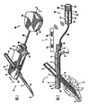
- FIG. 1 is a perspective view illustrating a subcutaneous sensor insertion set, a telemetered characteristic monitor transmitter device, and a data receiving device embodying features of the invention
- FIG. 2 is an enlarged longitudinal vertical section taken generally on the line 2-2 of FIG. 1 ;
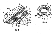
- FIG. 3 is an enlarged fragmented sectional view corresponding generally with the encircled region 3 of FIG. 2 ;
- FIG. 4 is an enlarged transverse section taken generally on the line 4-4 of FIG. 2 ;
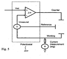
- FIG. 5 shows a potentiostat used in implementing a sensor-calibration method according to an embodiment of the invention
- FIG. 6A shows circuitry, components, and modules for implementing a sensor-calibration method according to an embodiment of the invention
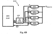
- FIG. 6B is block diagram of an ADC data-acquisition module in accordance with an embodiment of the present invention.
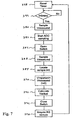
- FIG. 7 is a flow chart of the steps taken in implementing a sensor-calibration method according to an embodiment of the invention.
- FIG. 8 is a flow chart of the steps taken in implementing a sensor-calibration method according to an alternative embodiment of the invention.
- FIG. 9 is a plot diagram showing the exponential decay of a measured voltage over time.
- FIG. 10 is an enlarged view of the portion of the plot shown in FIG. 9 that corresponds to -0.1 msec. ⁇ t ⁇ +0.6 msec.
- These computer program instructions may also be stored in a computer-readable memory or medium that can direct a computer or other programmable data processing device to function in a particular manner, such that the instructions stored in the computer-readable memory or medium produce an article of manufacture including instructions which implement the function specified in the flowchart block or blocks.
- the computer program instructions may also be loaded onto a computer or other programmable data processing device to cause a series of operational steps to be performed on the computer or other programmable device to produce a computer-implemented process such that the instructions which execute on the computer or other programmable device provide steps for implementing the functions specified in the flowchart block or blocks presented herein.
- a telemetered characteristic monitor transmitter that is coupled to a sensor set and transmits data from the sensor set to a characteristic monitor for determining body characteristics.
- the sensor set may be implanted in and/or through subcutaneous, dermal, sub-dermal, inter-peritoneal or peritoneal tissue.
- the sensor set and monitor are for determining glucose levels in the blood and/or body fluids of the user without the use, or necessity, of a wire or cable connection between the transmitter and the monitor and, in certain embodiments, between the transmitter and sensor set.
- telemetered characteristic monitor system is primarily adapted for use in subcutaneous human tissue.
- still further embodiments may be placed in other types of tissue, such as muscle, lymph, organ tissue, veins, arteries or the like, and used in animal tissue Embodiments may provide sensor readings on an intermittent or continuous basis.
- the telemetered characteristic monitor system 1, in accordance with a preferred embodiment of the present invention includes a percutaneous sensor set 10, 200.
- the percutaneous sensor, set 10 utilizes an electrode-type sensor as described in more detail below.
- the system may use other types of sensors, such as chemical based, optimal based, or the like.
- the sensor may be of a type that is used on the external surface of the skin or placed below the skin layer of the user. Preferred embodiments of a surface-mounted sensor would utilize interstitial fluid harvested from underneath the skin.
- the telemetered characteristic monitor transmitter 100 generally includes the capability to transmit data.
- the telemetered characteristic monitor transmitter 100 may include a receiver, or the like, to facilitate two-way communication between the sensor set 10 and the characteristic monitor 200.
- the characteristic monitor 200 utilizes the transmitted data to determine the characteristic reading.
- the characteristic monitor 200 may be replaced with a data receiver, storage and/or transmitting device for later processing of the transmitted data or programming of the telemetered characteristic monitor transmitter 100.
- the telemetered characteristic monitor transmitter 100 transmits to an RF programmer, which acts as a relay, or shuttle, for data transmission between the sensor set 10 and a PC, laptop, Comrnunication-station, a data processor, or the like.
- Still further embodiments of the telemetered characteristic monitor transmitter 100 may have and use an input port for direct (e.g., wired) connection to a programming or data readout device.
- the telemetered characteristic monitor transmitter 100 takes characteristic information, such as glucose data or the like, from the percutaneous sensor set 10 and transmits it via wireless telemetry to the characteristic monitor 200, which displays and logs the received glucose readings. Logged data can be downloaded from the characteristic monitor 200 to a personal computer, laptop, or the like, for detailed data analysis.
- the telemetered characteristic monitor system 1 may be used in a hospital environment or the like.
- the telemetered characteristic monitor transmitter 100 an characteristic monitor 200 may also be combined with other medical devices to combine other patient data through a common data network and telemetry system.
- Fig. 1 is a perspective view of a subcutaneous sensor set 10 provided for subcutaneous placement of an active, portion of a flexible sensor 12 (see. Fig. 2 ), or the like, at a selected site in the body of a user.
- the subcutaneous or percutaneous portion of the sensor set 10 includes a hollow, slotted insertion needle 14, and a cannula 16.
- the needle 14 is used to facilitate quick and easy subcutaneous placement of the cannula 16 at the subcutaneous insertion site.
- a sensing portion 18 of the sensor 12 is used to expose one or more sensor electrodes 20 to the user's bodily fluids through a window 22 formed in the cannula 16.
- the one or more sensor electrodes 20 may include a counter electrode, a working electrode, and a reference electrode. See, e.g., Fig. 6A .
- the insertion needle 14 is withdrawn to leave the cannula 16 with the sensing portion 18 and the sensor electrodes 20 in place at the selected insertion site.
- the subcutaneous sensor set 10 facilitates accurate placement of a flexible thin film electrochemical sensor 12 of the type used for monitoring specific blood parameters representative of a user's condition.
- the sensor 12 may monitor glucose levels in the body, and may be used in conjunction with automated or semi-automated medication infusion pumps of the external or implantable type as described in U.S. Pat. Nos. 4,562,751 ; 4,678,408 ; 4,685,903 ; or 4,573,994 , to control delivery of insulin to a diabetic patient.
- Preferred embodiments of the flexible electrochemical sensor 12 are constructed in accordance with thin film mask techniques to include elongated thin film conductors embedded or encased between layers of a selected insulative material such as polyimide film or sheet, and membranes.
- the sensor electrodes 20 at a tip end of the sensing portion 18 are exposed through one of the insulative layers for direct contact with patient blood or other body fluids, when the sensing portion 18 (or active portion) of the sensor 12 is subcutaneously placed at an insertion site.
- the sensing portion 18 is joined to a connection portion 24 that terminates in conductive contact pads, or the like, which are also exposed through one of the insulative layers.
- other types of implantable sensors such as chemical based, optical based, or the like, may be used.
- connection portion 24 and the contact pads are generally adapted for a direct .wired electrical connection to a suitable monitor 200 for monitoring a user's condition in response to signals derived from the sensor electrodes 20.
- a suitable monitor 200 for monitoring a user's condition in response to signals derived from the sensor electrodes 20.
- the connection portion 24 may be conveniently connected electrically to the monitor 200 or a characteristic monitor transmitter 100 by a connector block 28 (or the like) as shown and described in U.S. Pat. No. 5,482,473 , entitled FLEX CIRCUIT CONNECTOR, which is also herein incorporated by reference.
- subcutaneous sensor set 10 may be configured or formed to work with either a wired or a wireless characteristic monitor system.
- the sensor electrodes 20 may be used in a variety of sensing applications and may be configured in a variety of ways.
- the sensor electrodes 20 may be used in physiological parameter sensing applications in which a biomolecule is used as a catalytic agent.
- the sensor electrodes 20 may be used in a glucose and oxygen sensor having a glucose oxidase enzyme catalyzing a reaction with the sensor electrodes 20.
- the sensor electrodes 20, along with a biomolecule or some other catalytic agent, may be placed in a human body in a vascular or non-vascular environment.
- the sensor electrodes 20 and biomolecule may be placed in a vein and subjected to a blood stream, or they may be placed in a subcutaneous or peritoneal region of the human body.
- the proximal part of the sensor 12 is mounted in a mounting base 30 adapted for placement onto the skin of a user.
- the mounting base 30 is a pad having an underside surface coated with a suitable pressure sensitive adhesive layer 32, with a peel-off paper strip 34 normally provided to cover and protect the adhesive layer 32, until the sensor set 10 is ready for use.
- the mounting base 30 includes upper and lower layers 36 and 38, with the connection portion 24 of the flexible sensor 12 being sandwiched between the layers 36 and 38.
- the connection portion 24 has a forward section joined to the active sensing portion 18 of the sensor 12, which is folded angularly to extend downwardly through a bore 40 formed in the lower base layer 38.
- the adhesive layer 32 includes an anti-bacterial agent to reduce the chance of infection; however, alternative embodiments may omit the agent.
- the mounting base is generally rectangular, but alternative embodiments may be other shapes, such as circular, oval, hour-glass, butterfly, irregular, or the like.
- the insertion needle 14 is adapted for slide-fit reception through a needle port 42 formed in the upper base layer 36 and further through the lower bore 40 in the lower base layer 38. As shown, the insertion needle 14 has a sharpened tip 44 and an open slot 46 which extends longitudinally from the tip 44 at the underside of the needle 14 to a position at least within the bore 40 in the lower base layer 36. Above the mounting base 30, the insertion needle 14 may have a full round cross-sectional shape, and may be closed off at a rear end of the needle 14. Further descriptions of the needle 14 and the sensor set 10 are found in U.S. Pat. Nos. 5,586,553 and 5,954,643 , which are herein incorporated by reference.
- the cannula 16 is best shown in Figs. 3 and 4 , and includes a first portion 48 having partly-circular cross-section to fit within the insertion needle 14 that extends downwardly from the mounting base 30.
- the first portion 48 may be formed with a solid core, rather than a hollow core.
- the cannula 16 is constructed from a suitable medical grade plastic or elastomer, such as polytetrafluoroethylene, silicone, or the like.
- the cannula 16 also defines an open lumen 50 in a second portion 52 for receiving, protecting and guideably supporting the sensing portion 18 of the sensor 12.
- the cannula 16 has one end fitted into the bore 40 formed in the lower layer 38 of the mounting base 30, and the cannula 16 is secured to the mounting base 30 by a suitable adhesive, ultrasonic welding, snap fit or other selected attachment method. From the mounting base 30, the cannula 16 extends angularly downwardly with the first portion 48 nested within the insertion needle 14, and terminates before the needle tip 44. At least one window 22 is formed in the lumen 50 near the implanted end 54, in general alignment with the sensor electrodes 20, to permit direct electrode exposure to the user's bodily fluid when the sensor 12 is subcutaneously placed. Alternatively, a membrane can cover this area with a porosity that controls rapid diffusion of glucose through the membrane.
- the telemetered characteristic monitor transmitter 100 is coupled to a sensor set 10 by a cable 102 through a connector 104 that is electrically coupled to the connector block 28 of the connector portion 24 of the sensor set 10.
- the cable 102 may be omitted, and the telemetered characteristic monitor transmitter 100 may include an appropriate connector (not shown) for direct to the connector portion 24 of the sensor set 10 or the sensor set 10 may be modified to have the connector portion 24 positioned at a different location, such as, for example, on the top of the sensor set 10 to facilitate placement of the telemetered characteristic monitor transmitter over the subcutaneous sensor set 10.
- the monitor transmitter 1.00 may be combined with the sensor set 10 (or sensor 12) as a single unit.
- the telemetered characteristic monitor transmitter 100 may omit the cable 102 and connector 104 and is instead optically coupled with an implanted sensor, in the subcutaneous, dermal, sub-dermal, inter-peritoneal or peritoneal tissue, to interrogate the implanted sensor using visible, and/or IR frequencies, either transmitting to, and receiving a signal from, the implanted sensor, or receiving a signal from the implanted sensor.
- the telemetered characteristic monitor transmitter 100 and the sensor set 10 may communicate wirelessly.
- the telemetered characteristic monitor 100 includes a housing 106 that supports a printed circuit board 108, batteries 110, antenna 112, and the cable 102 with the connector 104.
- the housing 106 is formed from an upper case 114 and a lower case 116 that are sealed with an ultrasonic weld to form a waterproof (or resistant) seal to permit cleaning by immersion (or swabbing) with water, cleaners, alcohol or the like.
- the upper and lower case 114 and 116 are formed from a medical grade plastic.
- the upper case 114 and lower case 116 may be connected together by other methods, such as snap fits, sealing rings, RTV (silicone sealant) and bonded together, or the like, or formed from other materials, such as metal, composites, ceramics, or the like.
- the separate case can be eliminated and the assembly is simply potted in epoxy or other moldable materials that is compatible with the electronics and reasonably moisture resistant.
- the lower case 116 may have an underside surface coated with a suitable pressure sensitive adhesive layer 118, with a peel-off paper strip 120 normally provided to cover and protect the adhesive layer 118, until the sensor set telemetered characteristic monitor transmitter 100 is ready for use.
- the monitor transmitter 100 may include a sensor interface (which connects with the cable 102), processing electronics, and data formatting electronics (not shown).
- the sensor interface, the processing electronics, and the data formatting electronics may be formed as separate semiconductor chips However, alternative embodiments may combine the various semiconductor chips into a single or multiple customized semiconductor chips.
- the telemetered characteristic monitor transmitter 100 provides power to the sensor set 10 through the cable 102 and cable connector 104.
- the power is used to monitor and drive the sensor set 10.
- the power connection is also used to speed the initialization of the sensor 12, when it is first placed under the skin. The use of an initialization process can reduce the time for sensor 12 stabilization from several hours to an hour or less.
- a reading may be transmitted from the sensor set 10 and the telemetered characteristic monitor transmitter 100 to the characteristic monitor 200, and then the user will input a calibrating glucose reading (e.g., by performing a finger stick) into characteristic monitor 200.
- a fluid containing a known value of glucose may be injected into the site around the sensor set 10, and then the reading is sent to the characteristic monitor 200 and the user inputs the known concentration value, presses a button (not shown) or otherwise instructs the monitor to calibrate using the known value.
- the telemetered characteristic monitor transmitter 100 checks to determine if the sensor set 10 is still connected. If the sensor set 10 is no longer connected, the telemetered characteristic monitor transmitter 100 will abort the stabilization process and sound an alarm (or send a signal to the characteristic monitor 200 to sound an alarm).
- the characteristic monitor 200 includes a telemetry receiver, a Telemetry Decoder (TD), and a host micro-controller (Host)--not shown--for communication with the telemetered characteristic monitor transmitter 100.
- the TD is used to decode a received telemetry signal from the transmitter device and forward the decoded signal to the Host, which may be a microprocessor for data reduction, data storage, user interface, or the like.
- the telemetry receiver receives the characteristic data (e.g., glucose data) from the telemetered characteristic monitor transmitter, and passes it to the TD for decoding and formatting.
- characteristic data e.g., glucose data
- the data is transferred to the Host for processing, where calibration information, based upon user entered characteristic readings (e.g., finger stick blood glucose readings); is performed to determine the corresponding characteristic level (e.g., glucose level) from measurement in the characteristic data (e.g., glucose data).
- the Host also provides for storage of historical characteristic data, and can download the data to a personal computer, lap-top, or the like, via a com-station, wireless connection, modem or the like.
- the counter electrode voltage is include in the message from the telemetered characteristic monitor transmitter 100 and is used as a diagnostic signal.
- the raw current signal values generally range from 0 to 999, which represents sensor electrode current in the range between 0.0 to 99.9 nanoAmperes, and is converted to characteristic values, such as glucose values in the range of 40 to 400 mg/dl. However, in alternative embodiments, larger or smaller ranges may be used.
- characteristic values such as glucose values in the range of 40 to 400 mg/dl. However, in alternative embodiments, larger or smaller ranges may be used.
- the values are then displayed on the characteristic monitor 200 or stored in data memory for later recall.
- the characteristic monitor 200 may be replaced by a different device.
- the telemetered characteristic monitor transmitter 100 communicates with an RF programmer (not shown) that is also used to program and obtain data from an infusion pump or the like.
- the RF programmer may also be used to update and program the transmitter 100, if the transmitter 100 includes a receiver for remote programming, calibration or data receipt.
- the RF programmer can be used to store data obtained from the sensor 12 and then provide it to either an infusion pump, characteristic monitor, computer or the like for analysis.
- the transmitter 100 may transmit the data to a medication delivery device, such as an infusion pump or the like, as part of a closed loop system.
- the transmitter 100 would include a transmitter to receive updates or requests for additional sensor data.
- An example of one type of RF programmer can be found in U.S. Patent No. 6,554,798 , which is herein incorporated by reference.
- the user programs the characteristic monitor (or it learns) the identification of the transmitter 100 and verifies proper operation and calibration of the transmitter 100.
- the characteristic monitor 200 and transmitter 100 then work to transmit and receive sensor data to determine characteristic levels.
- the sensor 12 is automatically initialized and readings are periodically transmitted, together with other information, to the characteristic monitor 200.
- sensor sensitivity may decrease as a direct result of an increase in additional resistances that tend to build up between the working and reference electrodes.
- This drift in sensitivity has an adverse effect on sensor stability, which necessitates more frequent sensor calibrations. Therefore, in order to more accurately control and measure the voltage across the electrochemical reaction being analyzed with a given sensor, and thereby reduce the necessity and frequency of external calibrations, it is important to remove (i.e., account for) any unwanted potentials which might exist across resistances in the vicinity of the electrodes. Once such unwanted potentials are accounted for, the sensor can be calibrated more accurately, in real time, and with little or no need for continual external calibrations by the user.
- a first level of sensor calibration may be implemented with standard potentiostat hardware.
- a potentiostat 300 may include an op amp 310 .that is connected in an electrical circuit so as to have two inputs: Vset and Vmeasured.
- Vmeasured is the measured value of the voltage between a reference electrode and a working electrode.
- Vset is the optimally desired voltage across the working and reference electrodes.
- the voltage between the working and reference electrodes is controlled by providing a current to the counter electrode.
- the current supply to the counter electrode is adjusted to return the potential to the set potential, thereby re-calibrating the sensor.
- the feed-back system of Fig. 5 addresses the build-up of additional resistances between the working and reference electrodes, it does so indirectly by measuring voltages at the various electrodes, as opposed to accounting more directly for the potential (i.e., IR) drop across any such additional resistances.
- the inherent voltage between the working and reference electrodes i.e., the "open-circuit" voltage
- the system depicted in Fig. 5 allows for a calibration process that is less-than-optimal and, as such, may require that a number of re-calibrations, including external inputs by the user, be performed on a frequent basis.
- Fig. 6A shows a sensor self-calibration module, including an electrical circuit, components, modules, etc., for implementing a self-calibration method according to an embodiment of the present invention.
- the self-calibration module includes a potentiostat 300 having an op amp 310.
- the op amp 310 is connected so as to have two inputs: Vactual and Vmeasured.
- Vmeasured is the measured value of the voltage between a working electrode 320c and a reference electrode 320b.
- the output of the op amp 310 is electrically connected to a counter electrode 320a via a current-interrupt switch 315.
- a real-time self-calibration method is initiated at step 380 with acquiring a sample measurement for Vmeasured while the current interrupt switch 315 is closed. Then, in step 382, with the switch 315 still closed, a sampling sub-routine is started wherein an analog-to-digital converter (ADC) module 330 having a plurality of ADCs is used to obtain a multiplicity of measurements for Vmeasured.
- ADC analog-to-digital converter
- the Vmeasured samples are obtained by said ADCs at a sample rate of about 1 MHz.
- the switch 315 is opened (step 384).
- the sampling of Vmeasured continues for a period of time after the switch 315 has been opened (step 386).
- a multiplicity of successive measurements are obtained for Vmeasured during a pre-determined time period that starts prior to, and ends after, the opening of the switch 315.
- the pre-determined time period may be about 100 ⁇ secs, and the time delay between successive ADC measurements may be about 1 ⁇ sec.
- the multiplicity of measurements for Vmeasured may be obtained for the range -1.0V ⁇ Vmeasured ⁇ +1.0V.
- Fig. 6B shows, for illustrative purposes, an example of how the multiplicity of Vmeasured samples may be obtained by high-frequency (i.e., in the MHz range) sampling.
- a plurality of ADCs 330a - 330n are connected in a circuit such that each ADC receives, successively, a respective sampled value for Vmeasured
- ADC 1 may receive the first sample, followed by ADC 2 receiving the second sample, ADC 3 receiving the third sample, and so on, until each one of the respective Vmeasured samples has been received by a different (succeeding) ADC.
- ADC 1 may receive the first sample, followed by ADC 2 receiving the second sample, ADC 3 receiving the third sample, and so on, until each one of the respective Vmeasured samples has been received by a different (succeeding) ADC.
- microprocessor unit (MPU) 338 transmits a signal through a line decoder 335 to request the sample obtained by a specific ADC.
- a signal with a value of a 0 -a 0 would notify ADC 1 that it should transmit its acquired sample to the MBU 338, while a signal with a value of a 0 -a 1 would notify ADC 2 to transmit its sample to the MPU 338, etc.
- ADC microprocessor unit
- the IR Calculation module 340 can then calculate the magnitude of the IR drop.
- the latter serves primarily as an intermediate vehicle through which the magnitude of another variable of utmost importance, i.e., Vimportant in Fig. 6A , is determined.
- Vimportant is indicative of the voltage that exists across the electrochemical reaction point.
- Vimportant is the "over potential" (i.e., the effective amount of potential that is not consumed by the unwanted resistances) that drives the electrochemical reaction at the working electrode 320c.
- the block diagram of Fig. 6A shows the circuitry, components, and modules that drive a sensor-calibration module in accordance with embodiments of the present invention (and in conjunction with a sensor of the type shown, e.g., in Figs. 1 and 2 ), to implement an IR compensation technique.
- the potentiostat 300 acts, essentially, as a first control unit (or sub-module) which is operative to ensure that Vmeasured is substantially equal to Vactual, wherein the latter is the second input to the comparator op amp 310.
- the sensor-calibration module may also include a second control unit (or sub-module) which is operative to ensure that Vimportant is substantially equal to Vset.
- Vset is the optimally desired voltage between the working electrode 320c and the reference electrode 320b; and may be pre-determined based on the value of current measurement(s) taken at node "A". in Fig. 6A . (see also step 396 in Fig. 7 ).
- the second control unit is a proportional-integral-derivative (PID) controller 350.
- the IR compensator portion of the circuit comprises a PID control loop, whereby Vimportant is driven to equal Vset in such a way as to ensure that Vmeasured equals Vactual.
- the PID controller may be implemented digitally in software, such that the PID control algorithm may be run on, e.g., a microprocessor within the second control unit. Depending on the specific sensor type and related circuitry, the control algorithm may also be run on the MPU 338, or other computer/processor within the sensor-calibration module. It is also noted that a digital-to-analog converter (DAC) module 360 may be employed to convert the outputted digital signal into an analog input signal to the op amp 310.
- DAC digital-to-analog converter
- the current interrupt switch 315 is closed (step 394), and the sensor is used to obtain a sample of the user characteristic that is being monitored by the characteristic monitoring system.
- BG blood glucose
- a current measurement is taken at point "A” and converted into a blood glucose level (by using, e.g., a single finger stick to calibrate current measurements for the specific user).
- the algorithm then loops back and resets the sensor-calibration module's timer (step 398).
- a typical delay time between successive BG samples may be about five minutes.
- a determination is made at step 399 as to whether five minutes have elapsed since the previous calibration of the sensor.
- step 396 If five minutes have passed; then the above-described process is repeated, except that, when step 396 is performed; there is no need for another finger stick, since a correlation between the user's BG level and the sensor's readings has been previously established. If, on the other hand, it is determined at step 399 that less than five minutes have passed since the immediately-previous calibration the algorithm loop back and retries until the elapsed time is equal to five minutes.
- Vimportant is indicative of the "over potential” that is available to drive the electrochemical reaction at the working electrode 320c.
- the more precise the measurement(s) of Vimportant the more precise and effective the sensor-calibration process described above.
- the working and reference electrodes have an inherent voltage between them. A more precise determination of Vimportant, therefore, would attempt to account for this inherent voltage.
- Fig. 8 shows a flow chart that depicts a self-calibration process in accordance with a more preferred embodiment of the invention. As shown, the process includes the same steps 380, 382, 384, 386, and 388 as those described in connection with Fig. 7 .
- the inherent voltage noted above is also measured.
- the inherent voltage is also called the open-circuit voltage (Voc) because its magnitude is obtained by leaving the switch 315 open long enough (e.g., less than 1 msec.) for the voltage between the working electrode 320c and the reference electrode 320b to stabilize to its steady-state, open-circuit value.
- Vmeasured the sample value obtained at step 380.
- Equation 1 differs from Equation 3 only by the additional term Voc.
- Vactual is computed in accordance with Equation 2 (step 392), where Vset is now defined as the optimally desired overpotential in the cell. Having the value for Vactual, the same steps 394, 396, 398, and 399 as in Fig. 7 are then followed to calibrate the sensor on a real-time basis.
- a sampling rate may be unachievable and/or impractical.
- the magnitude of the IR drop may be estimated at a lower sampling rate by backwards extrapolation.
- a multiplicity of measurements for Vmeasured are still obtained during a time period that starts prior to, and ends after, the opening of the switch 315. These measurements are then plotted against time. As shown in Fig. 9 , the voltage decays in a generally exponential manner. However, experiments have shown that the decay can be approximated as linear for about the first 0.5 milliseconds after the switch has been opened (i.e., until about t ⁇ 0.5 msec.). As such, an estimate of the decaying gradient can allow for a backwards-in-time extrapolation (to the point in time when the switch was opened) with generally as few as two or three sample points.
- Fig. 10 depicts an enlarged view of the first 0.5 msec. of the Vmeasured-vs.-time plot of Fig. 9 .
- a Vmeasured of 0.525V was observed with the current interrupt switch 315 closed.
- Vmeasured dropped to 0.5V before decaying exponentially. Therefore, Vmeasured at time t 0 is 0.5V, with an IR drop of 0.025V.
- the current-interrupt switch 315 may not be necessary at all.
- the IR drop may be measured by applying AC signals to the cell and analyzing the effect. More specifically, it is known that two resistances exist in series between the working and reference electrodes: The unwanted resistance across which the IR drop is observed, and the faradaic resistance whose potential is equal to Vimportant. In parallel with the faradic resistance is a capacitance that does not exist across the unwanted resistance. With this configuration, high-frequency signals passed between the working and reference electrodes would pass through the above-mentioned capacitance with no voltage drop, such that the capacitance behaves essentially as a short circuit.
- the capacitance behaves as an open circuit. Therefore, at high frequencies, where the faradic capacitance is effectively a short circuit, the unwanted resistance would be equal to the applied voltage divided by the cell current. With the unwanted resistance known, the IR drop may be calculated at a later time by multiplying the magnitude of the resistance by the cell current.
- the various alternative embodiments of the present invention are not necessarily mutually exclusive, and two or more self-calibration processes may be carried out together, wherein one approach may be used to verify the efficacy of another, or a primary and a secondary approach may be used to provide a redundancy in the system.
- one approach e.g., that depicted in Fig. 7
- a second approach e.g., that depicted in Fig. 8
- diagnostic purposes i.e., to check the status of a sensor, where an excessive IR drop, for example, would indicate a sensor malfunction
- the sensor-calibration module (including any microprocessors, controllers, and associated electronics), may be contained within the housing 106 of the transmitter device 100.
- the sensor-calibration module may be contained within the same housing as that of the sensor 12.
- the sensor-calibration module may be contained within the same housing as that of the data receiving device 200.
- the sensor, the transmitter device, and the data receiving device may communicate with one another either through an electrical cable or wirelessly.
- the electronic circuit has included an operational amplifier for measuring and controlling the voltage between the working and reference electrodes.
- any comparator circuit or differential amplifier may be used in place of the op amp.
- low current transistors such as, e.g., Field effect transistors (FET) and the like may be utilized to perform these functions.
Description
- This invention relates generally to subcutaneous and implantable sensor devices and, in particular embodiments, to methods and systems for providing real-time self-calibrating sensor devices.
- Over the years, a variety of electrochemical sensors have been developed for detecting and/or quantifying specific agents or compositions in a patient's blood. For instance, glucose sensors have been developed for use in obtaining an indication of blood glucose levels in a diabetic patient. Such readings are useful in monitoring and/or adjusting a treatment regimen which typically includes the regular administration of insulin to the patient.
- Generally, small and flexible electrochemical sensors can be used to obtain periodic readings over an extended period of time. In one form, flexible subcutaneous sensors are constructed in accordance with thin film mask techniques in which an elongated sensor includes thin film conductive elements encased between flexible insulative layers of polyimide sheets or similar material. Such thin film sensors typically include a plurality of exposed electrodes at one end for subcutaneous placement with a user's interstitial fluid, blood, or the like, and a corresponding exposed plurality of conductive contacts at another end for convenient external electrical connection with a suitable monitoring device through a wire or cable. Typical thin film sensors are described in commonly assigned
U.S. Pat. Nos. 5,390,671 ;5,391,250 ;5,482,473 ; and5,586,553 . See alsoU.S. Pat. No. 5,299,571 . - These electrochemical sensors have been applied in a telemetered characteristic monitor system. As described, e.g., in commonly-assigned
U.S. Pat. No. 6,809,653 , the telemetered system includes a remotely located data receiving device, a sensor for producing signals indicative of a characteristic of a user, and a transmitter device for processing signals received from the sensor and for wirelessly transmitting the processed signals to the remotely located data receiving device. The data receiving device may be a characteristic monitor, a data receiver that provides data to another device, an RF programmer, a medication delivery device (such as an infusion pump), or the like. - Regardless of whether the data receiving device (e.g., a glucose monitor), the transmitter device, and the sensor (e.g., a glucose sensor) communicate wirelessly or via an electrical wire connection, a characteristic monitoring system of the type described above is of practical use only after it has been calibrate based on the unique characteristics of the individual user. According to the current state of the art, for example as illustrated in document
WO 00/049941 - Such external calibrations, however, are disadvantageous for various reasons. For example, blood glucose meters are not perfectly accurate and include inherent margins of error. Moreover, even if completely accurate, blood glucose meters are susceptible to improper use; for example, if the user has handled candy or other sugar-containing substance immediately prior to performing the finger stick, with some of the sugar sticking to the user's fingers, the blood sugar analysis will result in an inaccurate blood sugar level indication. Furthermore, there is a cost, not to mention pain and discomfort, associated with each application of the finger stick.
- There is therefore a need for a real-time, self-calibrating sensor that reduces the frequency of, and potentially eliminates the need for, finger sticks. Sensors are known in other fields of application which use potentiostat and have a special test mode during which parameters of the sensor can be determined. One such sensor is shown in
US 6428684 . This is a gas sensor which relies on the analyte diffusing into a sensor cell where it causes current to flow between the electrodes of the potentiostat. During the test mode a switch is opened to remove the voltage from the counter electrode of the potentiostat causing the sensor to close to function. After a short period the switch is closed to resume normal functioning. During the interruption, however analyte builds up in the cell causing on initial spike in the measured reading. By composing the spike to the steady-state and the time of interruption the state of function of the cell is determined. - The present invention is as defined in
claims 1, 7 and 10 below. According to an embodiment of the invention, a system for calibrating a sensor of a characteristic monitoring system in real time utilizes a self-calibration module for periodic determination of, and compensation for, the IR drop across unwanted resistances in a cell. The self-calibration module includes a first control unit having a potentiostat, a second control unit, and a current-interrupt switch connected between the potentiostat and the sensor's counter electrode. The first control unit uses the potentiostat to ensure that a measured voltage across the sensor's working and reference electrodes (Vmeasured) is substantially equal to an input voltage (Vactual) of the potentiostat. The second control unit aims to ensure that the overpotential (Vimportant) in the cell is substantially equal to an optimally desired voltage across the sensor's working and reference, electrodes (Vset), where the "overpotential" may be defined as the effective amount of potential that is not consumed by the unwanted resistances and; as such drives the electrochemical reaction at the working electrode. In embodiments of the invention, the second control unit may employ a PID controller to calculate Vactual based on Vimportant. - In a particular embodiment of the invention, a method of calibrating the serisor in real time includes obtaining a value for Vmeasured, determining the magnitude of the IR drop, calculating the value of Vimportant by subtracting the magnitude of the IR drop from Vmeasured, and then using the first and second controllers, on a periodic basis, to determine Vactual based on Vset and Vimportant (i.e., the IR-compensated value of Vmeasured). Alternatively, Vimportant may be measured or approximated directly as the value of Vmeasured at the time the current-interrupt switch is opened.
- In embodiments of the invention, the IR drop may be measured by using a high-frequency (i.e., in the MHz range) ADC data-acquisition module to pinpoint the value of Vmeasured at the point in time when the current-interrupt switch was opened, and then subtracting this value from Vmeasured for the closed circuit. In an alternative embodiment, the magnitude of the IR drop may be estimated through linear regression of acquired samples of Vmeasured over time, where the samples are acquired at a lower rate. In addition, Vimportant may be optimized by also subtracting (from Vmeasured) the value of the open-circuit voltage (Voc) across the sensor's working and reference electrodes to account for the inherent potential that exists across these electrodes.
- The above-described steps may be repeated on a periodic basis, such that the sensor is self-calibrating, without the need for eternal calibration by the user. The repetition period may coincide, for example, with the delay time between successive samplings of the user characteristic being monitored by the characteristic monitoring system.
- Other features and advantages of the invention will become apparent from the following detailed description, taken in conjunction with the accompanying drawings which illustrate, by way of example, various features of embodiments of the invention.
- A detailed description of embodiments of the invention will be made with reference to the accompanying drawings, wherein like numerals designate corresponding parts in the several figures.
-
FIG. 1 is a perspective view illustrating a subcutaneous sensor insertion set, a telemetered characteristic monitor transmitter device, and a data receiving device embodying features of the invention; -
FIG. 2 is an enlarged longitudinal vertical section taken generally on the line 2-2 ofFIG. 1 ; -
FIG. 3 is an enlarged fragmented sectional view corresponding generally with theencircled region 3 ofFIG. 2 ; -
FIG. 4 is an enlarged transverse section taken generally on the line 4-4 ofFIG. 2 ; -
FIG. 5 shows a potentiostat used in implementing a sensor-calibration method according to an embodiment of the invention; -
FIG. 6A shows circuitry, components, and modules for implementing a sensor-calibration method according to an embodiment of the invention; -
FIG. 6B is block diagram of an ADC data-acquisition module in accordance with an embodiment of the present invention; -
FIG. 7 is a flow chart of the steps taken in implementing a sensor-calibration method according to an embodiment of the invention; -
FIG. 8 is a flow chart of the steps taken in implementing a sensor-calibration method according to an alternative embodiment of the invention; -
FIG. 9 is a plot diagram showing the exponential decay of a measured voltage over time; and -
FIG. 10 is an enlarged view of the portion of the plot shown inFIG. 9 that corresponds to -0.1 msec. ≤ t ≤ +0.6 msec. - In the following description, reference is made to the accompanying drawings which form a part hereof and which illustrate several embodiments of the present invention. It is understood that other embodiments may be utilized and structural and operational changes may be made without departing from the scope of the present invention.
- The present invention is described below with reference to flowchart illustrations of methods, apparatus, and computer program products. It will be understood that each block of the flowchart illustrations, and combinations of blocks in the flowchart illustrations, can be implemented by computer program instructions. Theses computer program instructions may be loaded onto a computer or other programmable data processing device (such as a controller, microcontroller, or processor) such that the instructions which execute on the computer or other programmable data processing device will implement the functions specified in the flowchart block or blocks. These computer program instructions may also be stored in a computer-readable memory or medium that can direct a computer or other programmable data processing device to function in a particular manner, such that the instructions stored in the computer-readable memory or medium produce an article of manufacture including instructions which implement the function specified in the flowchart block or blocks. The computer program instructions may also be loaded onto a computer or other programmable data processing device to cause a series of operational steps to be performed on the computer or other programmable device to produce a computer-implemented process such that the instructions which execute on the computer or other programmable device provide steps for implementing the functions specified in the flowchart block or blocks presented herein.
- As shown in the drawings for purposes of illustration, embodiments of the invention are described for use in conjunction with a telemetered characteristic monitor transmitter that is coupled to a sensor set and transmits data from the sensor set to a characteristic monitor for determining body characteristics. The sensor set may be implanted in and/or through subcutaneous, dermal, sub-dermal, inter-peritoneal or peritoneal tissue. In preferred embodiments of the present invention, the sensor set and monitor are for determining glucose levels in the blood and/or body fluids of the user without the use, or necessity, of a wire or cable connection between the transmitter and the monitor and, in certain embodiments, between the transmitter and sensor set. However, it will be recognized that further embodiments of the invention may be used to determine the levels of other agents, characteristics or compositions, such as hormones, cholesterol, medication concentrations, pH, oxygen saturation, viral loads (e.g., HIV), or the like. The telemetered characteristic monitor system is primarily adapted for use in subcutaneous human tissue. However, still further embodiments may be placed in other types of tissue, such as muscle, lymph, organ tissue, veins, arteries or the like, and used in animal tissue Embodiments may provide sensor readings on an intermittent or continuous basis.
- The telemetered characteristic monitor system 1, in accordance with a preferred embodiment of the present invention includes a percutaneous sensor set 10, 200. The percutaneous sensor, set 10 utilizes an electrode-type sensor as described in more detail below. However, in alternative embodiments, the system may use other types of sensors, such as chemical based, optimal based, or the like. In further alternative embodiments, the sensor may be of a type that is used on the external surface of the skin or placed below the skin layer of the user. Preferred embodiments of a surface-mounted sensor would utilize interstitial fluid harvested from underneath the skin. The telemetered characteristic monitor transmitter 100 generally includes the capability to transmit data. However, in alternative embodiments, the telemetered characteristic monitor transmitter 100 may include a receiver, or the like, to facilitate two-way communication between the sensor set 10 and the characteristic monitor 200. The characteristic monitor 200 utilizes the transmitted data to determine the characteristic reading. However, in alternative embodiments, the characteristic monitor 200 may be replaced with a data receiver, storage and/or transmitting device for later processing of the transmitted data or programming of the telemetered characteristic monitor transmitter 100. In further embodiments, the telemetered characteristic monitor transmitter 100 transmits to an RF programmer, which acts as a relay, or shuttle, for data transmission between the sensor set 10 and a PC, laptop, Comrnunication-station, a data processor, or the like. Still further embodiments of the telemetered characteristic monitor transmitter 100 may have and use an input port for direct (e.g., wired) connection to a programming or data readout device.
- The telemetered characteristic monitor transmitter 100 takes characteristic information, such as glucose data or the like, from the percutaneous sensor set 10 and transmits it via wireless telemetry to the characteristic monitor 200, which displays and logs the received glucose readings. Logged data can be downloaded from the characteristic monitor 200 to a personal computer, laptop, or the like, for detailed data analysis. In further embodiments, the telemetered characteristic monitor system 1 may be used in a hospital environment or the like. The telemetered characteristic monitor transmitter 100 an characteristic monitor 200 may also be combined with other medical devices to combine other patient data through a common data network and telemetry system.
-
Fig. 1 is a perspective view of a subcutaneous sensor set 10 provided for subcutaneous placement of an active, portion of a flexible sensor 12 (see.Fig. 2 ), or the like, at a selected site in the body of a user. The subcutaneous or percutaneous portion of the sensor set 10 includes a hollow, slottedinsertion needle 14, and acannula 16. Theneedle 14 is used to facilitate quick and easy subcutaneous placement of thecannula 16 at the subcutaneous insertion site. Inside thecannula 16 is asensing portion 18 of thesensor 12 to expose one ormore sensor electrodes 20 to the user's bodily fluids through awindow 22 formed in thecannula 16. In embodiments of the invention, the one ormore sensor electrodes 20 may include a counter electrode, a working electrode, and a reference electrode. See, e.g.,Fig. 6A . After insertion, theinsertion needle 14 is withdrawn to leave thecannula 16 with the sensingportion 18 and thesensor electrodes 20 in place at the selected insertion site. - In preferred embodiments, the subcutaneous sensor set 10 facilitates accurate placement of a flexible thin
film electrochemical sensor 12 of the type used for monitoring specific blood parameters representative of a user's condition. Thus, thesensor 12 may monitor glucose levels in the body, and may be used in conjunction with automated or semi-automated medication infusion pumps of the external or implantable type as described inU.S. Pat. Nos. 4,562,751 ;4,678,408 ;4,685,903 ; or4,573,994 , to control delivery of insulin to a diabetic patient. - Preferred embodiments of the flexible
electrochemical sensor 12 are constructed in accordance with thin film mask techniques to include elongated thin film conductors embedded or encased between layers of a selected insulative material such as polyimide film or sheet, and membranes. Thesensor electrodes 20 at a tip end of thesensing portion 18 are exposed through one of the insulative layers for direct contact with patient blood or other body fluids, when the sensing portion 18 (or active portion) of thesensor 12 is subcutaneously placed at an insertion site. The sensingportion 18 is joined to aconnection portion 24 that terminates in conductive contact pads, or the like, which are also exposed through one of the insulative layers. In alternative embodiments, other types of implantable sensors, such as chemical based, optical based, or the like, may be used. - As is known in the art, the
connection portion 24 and the contact pads are generally adapted for a direct .wired electrical connection to a suitable monitor 200 for monitoring a user's condition in response to signals derived from thesensor electrodes 20. Further description of flexible thin film sensors of this general type may be found inU.S. Pat. No. 5,391,250 , entitled METHOD OF FABRICATING THIN FILM SENSORS, which is herein incorporated by reference. Theconnection portion 24 may be conveniently connected electrically to the monitor 200 or a characteristic monitor transmitter 100 by a connector block 28 (or the like) as shown and described inU.S. Pat. No. 5,482,473 , entitled FLEX CIRCUIT CONNECTOR, which is also herein incorporated by reference. Thus, in accordance with embodiments of the present invention, subcutaneous sensor set 10 may be configured or formed to work with either a wired or a wireless characteristic monitor system. - The
sensor electrodes 20 may be used in a variety of sensing applications and may be configured in a variety of ways. For example, thesensor electrodes 20 may be used in physiological parameter sensing applications in which a biomolecule is used as a catalytic agent. Thus, thesensor electrodes 20 may be used in a glucose and oxygen sensor having a glucose oxidase enzyme catalyzing a reaction with thesensor electrodes 20. Thesensor electrodes 20, along with a biomolecule or some other catalytic agent, may be placed in a human body in a vascular or non-vascular environment. For example, thesensor electrodes 20 and biomolecule may be placed in a vein and subjected to a blood stream, or they may be placed in a subcutaneous or peritoneal region of the human body. - The proximal part of the
sensor 12 is mounted in a mounting base 30 adapted for placement onto the skin of a user. As shown, the mounting base 30 is a pad having an underside surface coated with a suitable pressure sensitive adhesive layer 32, with a peel-off paper strip 34 normally provided to cover and protect the adhesive layer 32, until the sensor set 10 is ready for use. As shown inFigs. 1 and 2 , the mounting base 30 includes upper and lower layers 36 and 38, with theconnection portion 24 of theflexible sensor 12 being sandwiched between the layers 36 and 38. Theconnection portion 24 has a forward section joined to theactive sensing portion 18 of thesensor 12, which is folded angularly to extend downwardly through a bore 40 formed in the lower base layer 38. In preferred embodiments, the adhesive layer 32 includes an anti-bacterial agent to reduce the chance of infection; however, alternative embodiments may omit the agent. In the illustrated embodiment, the mounting base is generally rectangular, but alternative embodiments may be other shapes, such as circular, oval, hour-glass, butterfly, irregular, or the like. - The
insertion needle 14 is adapted for slide-fit reception through a needle port 42 formed in the upper base layer 36 and further through the lower bore 40 in the lower base layer 38. As shown, theinsertion needle 14 has a sharpened tip 44 and an open slot 46 which extends longitudinally from the tip 44 at the underside of theneedle 14 to a position at least within the bore 40 in the lower base layer 36. Above the mounting base 30, theinsertion needle 14 may have a full round cross-sectional shape, and may be closed off at a rear end of theneedle 14. Further descriptions of theneedle 14 and the sensor set 10 are found inU.S. Pat. Nos. 5,586,553 and5,954,643 , which are herein incorporated by reference. - The
cannula 16 is best shown inFigs. 3 and 4 , and includes afirst portion 48 having partly-circular cross-section to fit within theinsertion needle 14 that extends downwardly from the mounting base 30. In alternative embodiments, thefirst portion 48 may be formed with a solid core, rather than a hollow core. In preferred embodiments, thecannula 16 is constructed from a suitable medical grade plastic or elastomer, such as polytetrafluoroethylene, silicone, or the like. Thecannula 16 also defines anopen lumen 50 in asecond portion 52 for receiving, protecting and guideably supporting thesensing portion 18 of thesensor 12. Thecannula 16 has one end fitted into the bore 40 formed in the lower layer 38 of the mounting base 30, and thecannula 16 is secured to the mounting base 30 by a suitable adhesive, ultrasonic welding, snap fit or other selected attachment method. From the mounting base 30, thecannula 16 extends angularly downwardly with thefirst portion 48 nested within theinsertion needle 14, and terminates before the needle tip 44. At least onewindow 22 is formed in thelumen 50 near the implantedend 54, in general alignment with thesensor electrodes 20, to permit direct electrode exposure to the user's bodily fluid when thesensor 12 is subcutaneously placed. Alternatively, a membrane can cover this area with a porosity that controls rapid diffusion of glucose through the membrane. - As shown in
Figs. 1 and 2 , the telemetered characteristic monitor transmitter 100 is coupled to a sensor set 10 by acable 102 through aconnector 104 that is electrically coupled to theconnector block 28 of theconnector portion 24 of the sensor set 10. In alternative embodiments, thecable 102 may be omitted, and the telemetered characteristic monitor transmitter 100 may include an appropriate connector (not shown) for direct to theconnector portion 24 of the sensor set 10 or the sensor set 10 may be modified to have theconnector portion 24 positioned at a different location, such as, for example, on the top of the sensor set 10 to facilitate placement of the telemetered characteristic monitor transmitter over the subcutaneous sensor set 10. In yet another embodiment, the monitor transmitter 1.00 may be combined with the sensor set 10 (or sensor 12) as a single unit. In further embodiments, the telemetered characteristic monitor transmitter 100 may omit thecable 102 andconnector 104 and is instead optically coupled with an implanted sensor, in the subcutaneous, dermal, sub-dermal, inter-peritoneal or peritoneal tissue, to interrogate the implanted sensor using visible, and/or IR frequencies, either transmitting to, and receiving a signal from, the implanted sensor, or receiving a signal from the implanted sensor. In yet another alternative embodiment, the telemetered characteristic monitor transmitter 100 and the sensor set 10 may communicate wirelessly. - The telemetered characteristic monitor 100 includes a housing 106 that supports a printed circuit board 108, batteries 110,
antenna 112, and thecable 102 with theconnector 104. In preferred embodiments, the housing 106 is formed from anupper case 114 and alower case 116 that are sealed with an ultrasonic weld to form a waterproof (or resistant) seal to permit cleaning by immersion (or swabbing) with water, cleaners, alcohol or the like. In preferred embodiments, the upper andlower case upper case 114 andlower case 116 may be connected together by other methods, such as snap fits, sealing rings, RTV (silicone sealant) and bonded together, or the like, or formed from other materials, such as metal, composites, ceramics, or the like. In other embodiments, the separate case can be eliminated and the assembly is simply potted in epoxy or other moldable materials that is compatible with the electronics and reasonably moisture resistant. As shown, thelower case 116 may have an underside surface coated with a suitable pressure sensitiveadhesive layer 118, with a peel-off paper strip 120 normally provided to cover and protect theadhesive layer 118, until the sensor set telemetered characteristic monitor transmitter 100 is ready for use. - The monitor transmitter 100 may include a sensor interface (which connects with the cable 102), processing electronics, and data formatting electronics (not shown). In embodiments of the invention, the sensor interface, the processing electronics, and the data formatting electronics may be formed as separate semiconductor chips However, alternative embodiments may combine the various semiconductor chips into a single or multiple customized semiconductor chips.
- In preferred embodiments, the telemetered characteristic monitor transmitter 100 provides power to the sensor set 10 through the
cable 102 andcable connector 104. The power is used to monitor and drive the sensor set 10. The power connection is also used to speed the initialization of thesensor 12, when it is first placed under the skin. The use of an initialization process can reduce the time forsensor 12 stabilization from several hours to an hour or less. - At the completion of the stabilizing process, a reading may be transmitted from the sensor set 10 and the telemetered characteristic monitor transmitter 100 to the characteristic monitor 200, and then the user will input a calibrating glucose reading (e.g., by performing a finger stick) into characteristic monitor 200. In alternative embodiments, a fluid containing a known value of glucose may be injected into the site around the sensor set 10, and then the reading is sent to the characteristic monitor 200 and the user inputs the known concentration value, presses a button (not shown) or otherwise instructs the monitor to calibrate using the known value. During the calibration process, the telemetered characteristic monitor transmitter 100 checks to determine if the sensor set 10 is still connected. If the sensor set 10 is no longer connected, the telemetered characteristic monitor transmitter 100 will abort the stabilization process and sound an alarm (or send a signal to the characteristic monitor 200 to sound an alarm).
- The characteristic monitor 200 includes a telemetry receiver, a Telemetry Decoder (TD), and a host micro-controller (Host)--not shown--for communication with the telemetered characteristic monitor transmitter 100. The TD is used to decode a received telemetry signal from the transmitter device and forward the decoded signal to the Host, which may be a microprocessor for data reduction, data storage, user interface, or the like. The telemetry receiver receives the characteristic data (e.g., glucose data) from the telemetered characteristic monitor transmitter, and passes it to the TD for decoding and formatting. After complete :receipt of the data by the TD, the data is transferred to the Host for processing, where calibration information, based upon user entered characteristic readings (e.g., finger stick blood glucose readings); is performed to determine the corresponding characteristic level (e.g., glucose level) from measurement in the characteristic data (e.g., glucose data). The Host also provides for storage of historical characteristic data, and can download the data to a personal computer, lap-top, or the like, via a com-station, wireless connection, modem or the like. For example, in certain embodiments, the counter electrode voltage is include in the message from the telemetered characteristic monitor transmitter 100 and is used as a diagnostic signal. The raw current signal values generally range from 0 to 999, which represents sensor electrode current in the range between 0.0 to 99.9 nanoAmperes, and is converted to characteristic values, such as glucose values in the range of 40 to 400 mg/dl. However, in alternative embodiments, larger or smaller ranges may be used. The values are then displayed on the characteristic monitor 200 or stored in data memory for later recall.
- In further embodiments of the present invention, the characteristic monitor 200 may be replaced by a different device. For example, in one embodiment, the telemetered characteristic monitor transmitter 100 communicates with an RF programmer (not shown) that is also used to program and obtain data from an infusion pump or the like. The RF programmer may also be used to update and program the transmitter 100, if the transmitter 100 includes a receiver for remote programming, calibration or data receipt. The RF programmer can be used to store data obtained from the
sensor 12 and then provide it to either an infusion pump, characteristic monitor, computer or the like for analysis. In further embodiments, the transmitter 100 may transmit the data to a medication delivery device, such as an infusion pump or the like, as part of a closed loop system. This would allow the medication delivery device to compare sensor results with medication delivery data and either sound alarms when appropriate or suggest corrections to the medication delivery regimen. In preferred embodiments, the transmitter 100 would include a transmitter to receive updates or requests for additional sensor data. An example of one type of RF programmer can be found inU.S. Patent No. 6,554,798 , which is herein incorporated by reference. - In use, once the sensor and transmitter have been properly positioned, the user programs the characteristic monitor (or it learns) the identification of the transmitter 100 and verifies proper operation and calibration of the transmitter 100. The characteristic monitor 200 and transmitter 100 then work to transmit and receive sensor data to determine characteristic levels. Thus, once a user attaches a transmitter 100 to a sensor set 10 (or otherwise initiates communication therebetween), the
sensor 12 is automatically initialized and readings are periodically transmitted, together with other information, to the characteristic monitor 200. - Once the
sensor 12 has been initialized, it must be ensured that thesensor 12, and the overall characteristic monitoring system, remain calibrated. Heretofore, this goal has been achieved via techniques in which a blood glucose meter and multiple blood tests are used to obtain reference glucose values which are then correlated with periodically-acquired glucose monitor data. Examples of such techniques may be found in commonly-assignedU.S. Application Publication No. 2005/0027177 andU.S. Patent Nos. 6,424,847 and6,895,263 , all of which are herein incorporated by reference. Thus, according to the current state of the art, the user is required to externally calibrate the sensor by utilizing a finger-stick blood glucose meter reading an average of two - four times per day for the duration that the characteristic monitor system is used. As noted previously, there are various disadvantages associated with such a technique. - To address these disadvantages, it has been found that, in sensors of the kind described herein, sensor sensitivity may decrease as a direct result of an increase in additional resistances that tend to build up between the working and reference electrodes. This drift in sensitivity, in turn, has an adverse effect on sensor stability, which necessitates more frequent sensor calibrations. Therefore, in order to more accurately control and measure the voltage across the electrochemical reaction being analyzed with a given sensor, and thereby reduce the necessity and frequency of external calibrations, it is important to remove (i.e., account for) any unwanted potentials which might exist across resistances in the vicinity of the electrodes. Once such unwanted potentials are accounted for, the sensor can be calibrated more accurately, in real time, and with little or no need for continual external calibrations by the user.
- Accordingly, in an embodiment of the present invention, a first level of sensor calibration may be implemented with standard potentiostat hardware. As shown in
Fig. 5 , such apotentiostat 300 may include anop amp 310 .that is connected in an electrical circuit so as to have two inputs: Vset and Vmeasured. As shown, Vmeasured is the measured value of the voltage between a reference electrode and a working electrode. Vset, on the other hand; is the optimally desired voltage across the working and reference electrodes. The voltage between the working and reference electrodes is controlled by providing a current to the counter electrode. Thus, when unwanted resistances cause the potential between the working and reference electrodes (i.e., Vmeasured inFig. 5 ) to deviate from Vset, the current supply to the counter electrode is adjusted to return the potential to the set potential, thereby re-calibrating the sensor. - However, although the feed-back system of
Fig. 5 addresses the build-up of additional resistances between the working and reference electrodes, it does so indirectly by measuring voltages at the various electrodes, as opposed to accounting more directly for the potential (i.e., IR) drop across any such additional resistances. In addition, the inherent voltage between the working and reference electrodes (i.e., the "open-circuit" voltage) is not accounted for. In short, the system depicted inFig. 5 allows for a calibration process that is less-than-optimal and, as such, may require that a number of re-calibrations, including external inputs by the user, be performed on a frequent basis. - In preferred embodiments of the invention, therefore, real-time self-calibration of the sensor is performed by using an IR compensation technique with a current interrupt. In this regard,
Fig. 6A shows a sensor self-calibration module, including an electrical circuit, components, modules, etc., for implementing a self-calibration method according to an embodiment of the present invention. As shown, the self-calibration module includes apotentiostat 300 having anop amp 310. Theop amp 310 is connected so as to have two inputs: Vactual and Vmeasured. As shown, Vmeasured is the measured value of the voltage between a workingelectrode 320c and a reference electrode 320b. The output of theop amp 310 is electrically connected to a counter electrode 320a via a current-interruptswitch 315. - It is known that, when the current in the circuit is interrupted, the voltage at node "V", where values for Vmeasured are obtained, immediately drops by the amount of voltage across the unwanted resistance, i.e., by an amount equal to the IR drop. The magnitude of the IR drop, therefore, may be measured by obtaining the value of Vmeasured while the circuit is still closed, obtaining the value of Vmeasured precisely at the point in time when the current interrupt
switch 315 is opened (i.e., t=0), and then subtracting the latter from the former. However, in practical terms, once theswitch 315 is opened, it takes Vmeasured on the order of micro-seconds to fall by an amount equal to the magnitude of the IR drop. As such, given the present technological limitations, it is often difficult, if not impossible, to pinpoint time t=0, and then measure a single value for Vmeasured at time t=0. - In light of the above, embodiments of the present invention utilize alternative methods for obtaining the value of Vmeasured at time t = 0. With reference to the flow chart of
Fig. 7 , a real-time self-calibration method according to one embodiment of the present invention is initiated atstep 380 with acquiring a sample measurement for Vmeasured while the current interruptswitch 315 is closed. Then, instep 382, with theswitch 315 still closed, a sampling sub-routine is started wherein an analog-to-digital converter (ADC)module 330 having a plurality of ADCs is used to obtain a multiplicity of measurements for Vmeasured. In a preferred embodiment, the Vmeasured samples are obtained by said ADCs at a sample rate of about 1 MHz. - After the sampling sub-routine has been initiated, the
switch 315 is opened (step 384). The sampling of Vmeasured, however, continues for a period of time after theswitch 315 has been opened (step 386). In this way, a multiplicity of successive measurements are obtained for Vmeasured during a pre-determined time period that starts prior to, and ends after, the opening of theswitch 315. In a preferred embodiment, the pre-determined time period may be about 100 µsecs, and the time delay between successive ADC measurements may be about 1 µsec. In addition, in a preferred embodiment, the multiplicity of measurements for Vmeasured may be obtained for the range -1.0V ≤ Vmeasured ≤ +1.0V. -
Fig. 6B shows, for illustrative purposes, an example of how the multiplicity of Vmeasured samples may be obtained by high-frequency (i.e., in the MHz range) sampling. As shown, a plurality of ADCs 330a - 330n are connected in a circuit such that each ADC receives, successively, a respective sampled value for Vmeasured Thus, when the sampling sub-routine starts, ADC1 may receive the first sample, followed by ADC2 receiving the second sample, ADC3 receiving the third sample, and so on, until each one of the respective Vmeasured samples has been received by a different (succeeding) ADC. Once the sub-routine has ended, a. microprocessor unit (MPU) 338 transmits a signal through aline decoder 335 to request the sample obtained by a specific ADC. Thus, for example, a signal with a value of a0-a0 would notify ADC1 that it should transmit its acquired sample to theMBU 338, while a signal with a value of a0-a1 would notify ADC2 to transmit its sample to theMPU 338, etc. It should be noted that, as shown by the line "A" inFig. 6B , only one ADC at a time may transmit its sample value to theMPU 338. - Once the successive ADC measurements have been processed (sequentially) by the
MPU 338, the processed data is searched to locate the sample of Vmeasured that was obtained at t = 0 (step 388). With this information, theIR Calculation module 340 can then calculate the magnitude of the IR drop. The latter, however, serves primarily as an intermediate vehicle through which the magnitude of another variable of utmost importance, i.e., Vimportant inFig. 6A , is determined. As can be deciphered fromFig. 6A , Vimportant is indicative of the voltage that exists across the electrochemical reaction point. That is, in light of the above discussion relating to additional, or unwanted, resistances in the cell, Vimportant is the "over potential" (i.e., the effective amount of potential that is not consumed by the unwanted resistances) that drives the electrochemical reaction at the workingelectrode 320c. Vimportant, therefore, may be obtained by the relation expressed in Equation 1:
where Vmeasuredt=0 is the value of Vmeasured at current interrupt time = 0, and Vmeasured is the sample value obtained atstep 380. Thus, atstep 390 inFig. 7 , the value of Vimportant is set to be equal to the value obtained by the ADCs for Vmeasured at t = 0. - As noted, the block diagram of
Fig. 6A shows the circuitry, components, and modules that drive a sensor-calibration module in accordance with embodiments of the present invention (and in conjunction with a sensor of the type shown, e.g., inFigs. 1 and 2 ), to implement an IR compensation technique. In the sensor-calibration module shown inFig. 6A , thepotentiostat 300 acts, essentially, as a first control unit (or sub-module) which is operative to ensure that Vmeasured is substantially equal to Vactual, wherein the latter is the second input to thecomparator op amp 310. - The sensor-calibration module, however, may also include a second control unit (or sub-module) which is operative to ensure that Vimportant is substantially equal to Vset. Vset is the optimally desired voltage between the working
electrode 320c and the reference electrode 320b; and may be pre-determined based on the value of current measurement(s) taken at node "A". inFig. 6A . (see also step 396 inFig. 7 ). In the configuration shown inFig.6A for illustrative purposes, the second control unit is a proportional-integral-derivative (PID)controller 350. Thus, in this configuration, the IR compensator portion of the circuit comprises a PID control loop, whereby Vimportant is driven to equal Vset in such a way as to ensure that Vmeasured equals Vactual. To do this, instep 392, Vactual is computed based on Equation 2:
where e is the difference between Vset and Vimportant, t is time, Kp is the proportional gain, Kd is the differential gain, and Ki is the integral gain. It is noted that the PID controller may be implemented digitally in software, such that the PID control algorithm may be run on, e.g., a microprocessor within the second control unit. Depending on the specific sensor type and related circuitry, the control algorithm may also be run on theMPU 338, or other computer/processor within the sensor-calibration module. It is also noted that a digital-to-analog converter (DAC)module 360 may be employed to convert the outputted digital signal into an analog input signal to theop amp 310. - Once Vactual has been calculated, the current interrupt
switch 315 is closed (step 394), and the sensor is used to obtain a sample of the user characteristic that is being monitored by the characteristic monitoring system. InFig. 7 , blood glucose (BG) is shown, for purposes of illustration, as the user characteristic of interest. Thus, once theswitch 315 has been closed, atstep 396, a current measurement is taken at point "A" and converted into a blood glucose level (by using, e.g., a single finger stick to calibrate current measurements for the specific user). - The algorithm then loops back and resets the sensor-calibration module's timer (step 398). Again, with the illustrative example of monitoring blood glucose levels in a user, a typical delay time between successive BG samples may be about five minutes. In a preferred embodiment, it is therefore desirable to have the sensor calibrated at least as frequently as the rate of acquisition of BG samples, and just prior to the BG sample being taken. As such, in one embodiment, once the timer has been reset, a determination is made at
step 399 as to whether five minutes have elapsed since the previous calibration of the sensor. If five minutes have passed; then the above-described process is repeated, except that, whenstep 396 is performed; there is no need for another finger stick, since a correlation between the user's BG level and the sensor's readings has been previously established. If, on the other hand, it is determined atstep 399 that less than five minutes have passed since the immediately-previous calibration the algorithm loop back and retries until the elapsed time is equal to five minutes. - As noted previously, Vimportant is indicative of the "over potential" that is available to drive the electrochemical reaction at the working
electrode 320c. Thus, the more precise the measurement(s) of Vimportant, the more precise and effective the sensor-calibration process described above. In this regard, it is known that, because they are made of different materials, the working and reference electrodes have an inherent voltage between them. A more precise determination of Vimportant, therefore, would attempt to account for this inherent voltage. -
Fig. 8 shows a flow chart that depicts a self-calibration process in accordance with a more preferred embodiment of the invention. As shown, the process includes thesame steps Fig. 7 . However, in this alternative embodiment, in addition to determining the value of Vmeasured at t = 0, the inherent voltage noted above is also measured. The inherent voltage is also called the open-circuit voltage (Voc) because its magnitude is obtained by leaving theswitch 315 open long enough (e.g., less than 1 msec.) for the voltage between the workingelectrode 320c and the reference electrode 320b to stabilize to its steady-state, open-circuit value. As this point, Voc is measured (step 389), and Vimportant is calculated in accordance with Equation 3:
where, as in Equation 1, Vmeasuredt=0 is the value of Vmeasured at current interrupt time = 0, and Vmeasured is the sample value obtained atstep 380. It is noted that Equation 1 differs fromEquation 3 only by the additional term Voc. Once Vimportant has been calculated (step 390a), Vactual is computed in accordance with Equation 2 (step 392), where Vset is now defined as the optimally desired overpotential in the cell. Having the value for Vactual, thesame steps Fig. 7 are then followed to calibrate the sensor on a real-time basis. - The real-time, self-calibration techniques for IR compensation depicted in
Figs.7 and8 require that a relatively high, uniform sampling rate be used (through theADC module 330, e.g.) in order to ascertain the value of Vmeasuredt=0. However, depending on the specific application, such a sampling rate may be unachievable and/or impractical. As such, in a alternative embodiment of the present invention, the magnitude of the IR drop may be estimated at a lower sampling rate by backwards extrapolation. - More specifically, in this alternative embodiment, a multiplicity of measurements for Vmeasured are still obtained during a time period that starts prior to, and ends after, the opening of the
switch 315. These measurements are then plotted against time. As shown inFig. 9 , the voltage decays in a generally exponential manner. However, experiments have shown that the decay can be approximated as linear for about the first 0.5 milliseconds after the switch has been opened (i.e., until about t ≈ 0.5 msec.). As such, an estimate of the decaying gradient can allow for a backwards-in-time extrapolation (to the point in time when the switch was opened) with generally as few as two or three sample points. - Thus, by way of example,
Fig. 9 illustrates the results of an experiment in which samples were acquired at times t ≈ 0.1 msec., t ≈ 0.2 msec., and t ≈ 0.5 msec., and linear regression was performed to backward extrapolate to time t = 0 to obtain an approximate value for Vmeasuredt=0. As shown in the Vmeasured-vs.-time plot, the exponential decay of Vmeasured can be estimated as linear for approximately the first 0.5 msec., and a regression line generated, such that an estimated value can be obtained for Vmeasured at time t = 0. -
Fig. 10 depicts an enlarged view of the first 0.5 msec. of the Vmeasured-vs.-time plot ofFig. 9 . For the purposes of the experiment, a Vmeasured of 0.525V was observed with the current interruptswitch 315 closed. When the switch was opened, Vmeasured dropped to 0.5V before decaying exponentially. Therefore, Vmeasured at time t = 0 is 0.5V, with an IR drop of 0.025V. Using backwards-in-time extrapolation, a regression line was then calculated as previously described, which resulted in an estimated Vmeasuredt=0 value of 0.49V, with an IR drop of 0.035V. This resulted in a measurement error of approximately 2%, which may, depending on the specific application, prove to be trivial. Of course, once an approximate value for Vmeasuredt=0 has been obtained, the remainder of the self-calibration process is carried out as, shown inFigs. 7 and8 . - In yet other alternative embodiments of the invention, the current-interrupt
switch 315 may not be necessary at all. Thus, in one such embodiment, the IR drop may be measured by applying AC signals to the cell and analyzing the effect. More specifically, it is known that two resistances exist in series between the working and reference electrodes: The unwanted resistance across which the IR drop is observed, and the faradaic resistance whose potential is equal to Vimportant. In parallel with the faradic resistance is a capacitance that does not exist across the unwanted resistance. With this configuration, high-frequency signals passed between the working and reference electrodes would pass through the above-mentioned capacitance with no voltage drop, such that the capacitance behaves essentially as a short circuit. When, on the other hand, low-frequency signals are applied, the capacitance behaves as an open circuit. Therefore, at high frequencies, where the faradic capacitance is effectively a short circuit, the unwanted resistance would be equal to the applied voltage divided by the cell current. With the unwanted resistance known, the IR drop may be calculated at a later time by multiplying the magnitude of the resistance by the cell current. - It should be noted that the various alternative embodiments of the present invention are not necessarily mutually exclusive, and two or more self-calibration processes may be carried out together, wherein one approach may be used to verify the efficacy of another, or a primary and a secondary approach may be used to provide a redundancy in the system. In addition, one approach, e.g., that depicted in
Fig. 7 , may be used for control purposes (i.e., for real-time self-calibration of the sensor), while a second approach, e.g., that depicted inFig. 8 , is used for diagnostic purposes (i.e., to check the status of a sensor, where an excessive IR drop, for example, would indicate a sensor malfunction), or vice versa. - In addition, embodiments of the present invention have been described in connection with specific circuit configurations and/or electronic components, modules, sub-modules, etc. However, various alternatives may be used, all of which are intended to be covered by the claims herein. For example, with reference to.
Figs. 1 and 2 , in a self-calibrating characteristic monitoring system in accordance with embodiments of the invention, the sensor-calibration module (including any microprocessors, controllers, and associated electronics), may be contained within the housing 106 of the transmitter device 100. Alternatively, the sensor-calibration module may be contained within the same housing as that of thesensor 12. In yet a third embodiment, the sensor-calibration module may be contained within the same housing as that of the data receiving device 200. Moreover, the sensor, the transmitter device, and the data receiving device may communicate with one another either through an electrical cable or wirelessly. - Similarly, in various embodiments of the invention described herein, the electronic circuit has included an operational amplifier for measuring and controlling the voltage between the working and reference electrodes. However, any comparator circuit or differential amplifier may be used in place of the op amp. Specifically, low current transistors, such as, e.g., Field effect transistors (FET) and the like may be utilized to perform these functions.
Claims (9)
- A self-calibrating characteristic monitoring system for monitoring a characteristic of a user's blood or interstitial fluid, said system comprising:a sensor for producing a signal indicative of said characteristic, the sensor including a counter electrode (320a), a reference electrode (320b), and a working electrode (320c) in communication with the user's blood or interstitial fluids;a sensor-calibration module having a first control unit, wherein the first control unit comprises an operational amplifier (op amp) (310) connected in an electrical circuit such that a first voltage V1 equal to the measured difference between the working electrode voltage and the reference electrode voltage provides a first input into the op amp (310), a second voltage V2 provides a second input into the op amp (310), and the output of the op amp (310) is electrically connected to the counter electrode (320a) via a current-interrupt switch (315), said sensor-calibration module being configured to calibrate the sensor based on the value of the first voltage V1 and the magnitude of an IR drop due to a resistance between the reference and working electrodes; anda remotely located data receiving device for receiving data indicative of said characteristic based on said signal;wherein the sensor-calibration module further includes a second control unit having a microprocessor (338) and a machine-readable medium encoded with instructions that, when executed, cause the microprocessor (338) to perform a calibration process comprising:a. obtaining a measurement for said first voltage V1 at a time when the current-interrupt switch (315) is closed;b. transmitting an instruction to open the switch (315) while obtaining a multiplicity of successive measurements for said first voltage V1 during a pre-determined time period that starts prior to, and ends after, the opening of the switch (315);c. determining the magnitude of a third voltage V3=VIt=0, wherein the third voltage V3 is indicative of an overpotential at the working electrode, and V1t=0 is the magnitude of V1 at the point in time when the switch (315) is opened;d. based on the determined value of the third voltage V3 and a voltage Vset, calculating the second voltage V2 in such a way as to have the third voltage V3 become substantially equal to Vset, wherein Vset is the optimally desired voltage between the working and reference electrodes; ande. transmitting an instruction to close the current-interrupt switch (315) and apply the calculated value of the second voltageV2 as said second input to the op amp of the first control unit;wherein in step (d) of the calibration process, the second voltage V2 is calculated in accordance with the relation,

- The system of claim 1, wherein said characteristic is a glucose level in the body of the user, and the data receiving device is an insulin pump.
- The system of claim 1, further including a transmitter device that is in communication with the sensor to receive signals therefrom, said transmitter device including a processor to process the signals from the sensor and a transmitter for wirelessly transmitting the processed signals to the data receiving device.
- The system of claim 1, wherein said second control unit further includes a plurality of analog-to-digital converters (ADC's) that are electrically connected to said first control unit for obtaining said multiplicity of measurements for the first voltage V1, each said ADC having a conversion time that is greater than 1 µsec.
- The system of claim 1, wherein the multiplicity of measurements for the first voltage V1 are sent by the plurality of ADC's to said microprocessor and, in step c) of the calibration process, the microprocessor determines the magnitude of the third voltage V3 as the measured value of the first voltage V1 at time t = 0 within said predetermined time period when the switch was opened.
- The system of claim 1, wherein said predetermined time period lasts until at least 0.5 msecs after the switch (315) has been opened, and in step c) of the calibration process, said multiplicity of measurements for the first voltage V1 are plotted against time and an approximate value for the third voltage V3 is determined through linear regression.
- A method of calibrating a sensor configured to produce a signal indicative of a characteristic of a user's blood or interstitial fluid, wherein the sensor includes a counter electrode (320a), a reference electrode (320b), and a working electrode (320c), said electrodes being in communication with the user's blood or interstitial fluids and connected in an electrical circuit such that a first voltage V1 equal to the difference between the working electrode voltage and the reference electrode voltage provides a first input into a comparator, a second voltage V2 provides a second input into the comparator, and the output of the comparator is electrically connected to the counter electrode, said method comprising:a. measuring the first voltage V1 between the working and reference electrodes;b. determining the magnitude of a third voltage V3, wherein the third voltage V3 is indicative of an overpotential at the working electrode;c. based on the determined value of the third voltage V3 and a voltage Vset, calculating the second voltage V2 in such a way as to have the third voltage V3 become substantially equal to Vset, wherein Vset is the optimally desired voltage between the working and reference electrodes; andd. applying the calculated value of the second voltage V2 as said second input to the comparator;wherein the second voltage V2 is calculated in accordance with the relation

- The method of claim 7, wherein said comparator is an op amp.
- A machine-readable medium for use in conjunction with a system in accordance with any of claims 1-6 said medium being encoded with instructions that, when executed, cause a computer to perform a sensor-calibration process comprising:a) obtaining a measurement for the first voltage V1 at a time when the current-interrupt switch (315) is closed;b) transmitting an instruction to open the switch (315) while obtaining a multiplicity of successive measurements for the first voltage V1 during a pre-determined time period that starts prior to, and ends after, the opening of the switch (315);c) determining the magnitude of the voltage V3 =V1t=0 wherein the third voltage V3 is indicative of an overpotential at the working electrode, and V1t=0 is the magnitude of the first voltage V1 at the point in time when the switch (315) is opened;d) based on the determined value of the third voltage V3 and the voltage Vset, calculating the second voltage V2 in such a way as to have the third voltage V3 become substantially equal to Vset, wherein Vset is the optimally desired voltage between the working electrode (320c) and reference electrode (320b); ande) transmitting an instruction to close the current-interrupt switch (315) and apply the calculated value of the second voltage V2 as said second input to the op amp;wherein, in step (d) of the sensor- calibration process, the applied voltage V2 is calculated in accordance with the relation

Priority Applications (1)
| Application Number | Priority Date | Filing Date | Title |
|---|---|---|---|
| EP11188435A EP2442101A1 (en) | 2005-12-30 | 2006-12-21 | Real-time self-calibrating sensor system and method |
Applications Claiming Priority (2)
| Application Number | Priority Date | Filing Date | Title |
|---|---|---|---|
| US11/323,216 US7774038B2 (en) | 2005-12-30 | 2005-12-30 | Real-time self-calibrating sensor system and method |
| PCT/US2006/049015 WO2007079025A2 (en) | 2005-12-30 | 2006-12-21 | Real-time self-calibrating sensor system and method |
Related Child Applications (1)
| Application Number | Title | Priority Date | Filing Date |
|---|---|---|---|
| EP11188435A Division-Into EP2442101A1 (en) | 2005-12-30 | 2006-12-21 | Real-time self-calibrating sensor system and method |
Publications (2)
| Publication Number | Publication Date |
|---|---|
| EP1968448A2 EP1968448A2 (en) | 2008-09-17 |
| EP1968448B1 true EP1968448B1 (en) | 2012-10-03 |
Family
ID=38228792
Family Applications (2)
| Application Number | Title | Priority Date | Filing Date |
|---|---|---|---|
| EP06846003A Active EP1968448B1 (en) | 2005-12-30 | 2006-12-21 | Real-time self-calibrating sensor system and method |
| EP11188435A Withdrawn EP2442101A1 (en) | 2005-12-30 | 2006-12-21 | Real-time self-calibrating sensor system and method |
Family Applications After (1)
| Application Number | Title | Priority Date | Filing Date |
|---|---|---|---|
| EP11188435A Withdrawn EP2442101A1 (en) | 2005-12-30 | 2006-12-21 | Real-time self-calibrating sensor system and method |
Country Status (6)
| Country | Link |
|---|---|
| US (4) | US7774038B2 (en) |
| EP (2) | EP1968448B1 (en) |
| JP (1) | JP2009521999A (en) |
| CA (2) | CA2882514C (en) |
| DK (1) | DK1968448T3 (en) |
| WO (1) | WO2007079025A2 (en) |
Families Citing this family (79)
| Publication number | Priority date | Publication date | Assignee | Title |
|---|---|---|---|---|
| US8858434B2 (en) | 2004-07-13 | 2014-10-14 | Dexcom, Inc. | Transcutaneous analyte sensor |
| US20190357827A1 (en) | 2003-08-01 | 2019-11-28 | Dexcom, Inc. | Analyte sensor |
| US7920906B2 (en) | 2005-03-10 | 2011-04-05 | Dexcom, Inc. | System and methods for processing analyte sensor data for sensor calibration |
| US7299082B2 (en) * | 2003-10-31 | 2007-11-20 | Abbott Diabetes Care, Inc. | Method of calibrating an analyte-measurement device, and associated methods, devices and systems |
| US9247900B2 (en) | 2004-07-13 | 2016-02-02 | Dexcom, Inc. | Analyte sensor |
| US20060270922A1 (en) | 2004-07-13 | 2006-11-30 | Brauker James H | Analyte sensor |
| US7545272B2 (en) | 2005-02-08 | 2009-06-09 | Therasense, Inc. | RF tag on test strips, test strip vials and boxes |
| US7774038B2 (en) * | 2005-12-30 | 2010-08-10 | Medtronic Minimed, Inc. | Real-time self-calibrating sensor system and method |
| US8114269B2 (en) * | 2005-12-30 | 2012-02-14 | Medtronic Minimed, Inc. | System and method for determining the point of hydration and proper time to apply potential to a glucose sensor |
| US7885698B2 (en) | 2006-02-28 | 2011-02-08 | Abbott Diabetes Care Inc. | Method and system for providing continuous calibration of implantable analyte sensors |
| WO2008137716A2 (en) * | 2007-05-04 | 2008-11-13 | Tecella, Llc | Subsystems and methods for use in patch clamp systems |
| ATE530110T1 (en) * | 2007-09-01 | 2011-11-15 | Hoffmann La Roche | MEASURING SYSTEM FOR MONITORING AN ANALYTE CONCENTRATION IN VIVO AND METHOD FOR DETECTING A MALFUNCTION OF SUCH A MEASURING SYSTEM |
| US20090085768A1 (en) * | 2007-10-02 | 2009-04-02 | Medtronic Minimed, Inc. | Glucose sensor transceiver |
| US20090177147A1 (en) | 2008-01-07 | 2009-07-09 | Michael Blomquist | Insulin pump with insulin therapy coaching |
| CA2715628A1 (en) | 2008-02-21 | 2009-08-27 | Dexcom, Inc. | Systems and methods for processing, transmitting and displaying sensor data |
| US8583204B2 (en) | 2008-03-28 | 2013-11-12 | Dexcom, Inc. | Polymer membranes for continuous analyte sensors |
| US8682408B2 (en) | 2008-03-28 | 2014-03-25 | Dexcom, Inc. | Polymer membranes for continuous analyte sensors |
| US11730407B2 (en) | 2008-03-28 | 2023-08-22 | Dexcom, Inc. | Polymer membranes for continuous analyte sensors |
| JP5738752B2 (en) * | 2008-04-15 | 2015-06-24 | ノニン・メディカル・インコーポレーテッド | Non-invasive optical sensor |
| US20100169035A1 (en) * | 2008-12-29 | 2010-07-01 | Medtronic Minimed, Inc. | Methods and systems for observing sensor parameters |
| GR1007310B (en) | 2009-03-09 | 2011-06-10 | Αχιλλεας Τσουκαλης | Implantable biosensor with automatic calibration |
| US20110027458A1 (en) | 2009-07-02 | 2011-02-03 | Dexcom, Inc. | Continuous analyte sensors and methods of making same |
| US9351677B2 (en) | 2009-07-02 | 2016-05-31 | Dexcom, Inc. | Analyte sensor with increased reference capacity |
| CA2769030C (en) | 2009-07-30 | 2016-05-10 | Tandem Diabetes Care, Inc. | Infusion pump system with disposable cartridge having pressure venting and pressure feedback |
| US20110288388A1 (en) | 2009-11-20 | 2011-11-24 | Medtronic Minimed, Inc. | Multi-conductor lead configurations useful with medical device systems and methods for making and using them |
| US20110199094A1 (en) * | 2010-02-16 | 2011-08-18 | Hamilton Sundstrand Corporation | Gas Sensor Age Compensation and Failure Detection |
| US10448872B2 (en) | 2010-03-16 | 2019-10-22 | Medtronic Minimed, Inc. | Analyte sensor apparatuses having improved electrode configurations and methods for making and using them |
| JP2012032206A (en) * | 2010-07-29 | 2012-02-16 | National Institute Of Advanced Industrial & Technology | Electrochemical analysis device |
| WO2012142502A2 (en) | 2011-04-15 | 2012-10-18 | Dexcom Inc. | Advanced analyte sensor calibration and error detection |
| US9008744B2 (en) | 2011-05-06 | 2015-04-14 | Medtronic Minimed, Inc. | Method and apparatus for continuous analyte monitoring |
| US10010274B2 (en) | 2011-12-16 | 2018-07-03 | James Winkelman | Systems, devices and methods for in situ calibration of implantable sensors |
| US9433376B2 (en) | 2012-03-16 | 2016-09-06 | Dexcom, Inc. | Systems and methods for processing analyte sensor data |
| US9180242B2 (en) | 2012-05-17 | 2015-11-10 | Tandem Diabetes Care, Inc. | Methods and devices for multiple fluid transfer |
| US9493807B2 (en) | 2012-05-25 | 2016-11-15 | Medtronic Minimed, Inc. | Foldover sensors and methods for making and using them |
| US9238100B2 (en) | 2012-06-07 | 2016-01-19 | Tandem Diabetes Care, Inc. | Device and method for training users of ambulatory medical devices |
| US9970894B2 (en) | 2012-06-21 | 2018-05-15 | Sunvou Medical Electronics Co., Ltd. | Method and device for measuring concentration of substance in fluid |
| US20140012115A1 (en) | 2012-07-03 | 2014-01-09 | Medtronic Minimed, Inc. | Plasma deposited adhesion promoter layers for use with analyte sensors |
| US9119529B2 (en) | 2012-10-30 | 2015-09-01 | Dexcom, Inc. | Systems and methods for dynamically and intelligently monitoring a host's glycemic condition after an alert is triggered |
| US10194840B2 (en) | 2012-12-06 | 2019-02-05 | Medtronic Minimed, Inc. | Microarray electrodes useful with analyte sensors and methods for making and using them |
| US10426383B2 (en) | 2013-01-22 | 2019-10-01 | Medtronic Minimed, Inc. | Muting glucose sensor oxygen response and reducing electrode edge growth with pulsed current plating |
| US9173998B2 (en) | 2013-03-14 | 2015-11-03 | Tandem Diabetes Care, Inc. | System and method for detecting occlusions in an infusion pump |
| US9242043B2 (en) | 2013-03-15 | 2016-01-26 | Tandem Diabetes Care, Inc. | Field update of an ambulatory infusion pump system |
| ES2647815T3 (en) * | 2013-06-20 | 2017-12-26 | Siemens Schweiz Ag | Functional control of an electrolytic gas sensor with three electrodes, as well as danger alarm and gas meter |
| TWI510877B (en) | 2013-10-23 | 2015-12-01 | Ind Tech Res Inst | Voltage compensation circuit and control method thereof |
| US20150122647A1 (en) | 2013-11-07 | 2015-05-07 | Medtronic Minimed, Inc. | Enzyme matrices for use with ethylene oxide sterilization |
| WO2015102745A1 (en) | 2013-12-31 | 2015-07-09 | Abbott Diabetes Care Inc. | Self-powered analyte sensor and devices using the same |
| US9983167B2 (en) | 2014-10-31 | 2018-05-29 | Zansors, Llc | Multichannel potentiostat analyzer system and methods |
| TWI533319B (en) | 2014-11-20 | 2016-05-11 | 財團法人工業技術研究院 | Non-volatile memory device and control method thereof |
| US9798886B2 (en) | 2015-07-08 | 2017-10-24 | International Business Machines Corporation | Bio-medical sensing platform |
| US11298059B2 (en) | 2016-05-13 | 2022-04-12 | PercuSense, Inc. | Analyte sensor |
| US11134868B2 (en) | 2017-03-17 | 2021-10-05 | Medtronic Minimed, Inc. | Metal pillar device structures and methods for making and using them in electrochemical and/or electrocatalytic applications |
| US10856784B2 (en) | 2017-06-30 | 2020-12-08 | Medtronic Minimed, Inc. | Sensor initialization methods for faster body sensor response |
| CN107561147B (en) * | 2017-08-31 | 2020-02-04 | 三诺生物传感股份有限公司 | Detection circuit, calibration method and device for current of glucometer |
| CN212438615U (en) | 2017-10-24 | 2021-02-02 | 德克斯康公司 | Wearable device |
| US11331022B2 (en) | 2017-10-24 | 2022-05-17 | Dexcom, Inc. | Pre-connected analyte sensors |
| CN111683592B (en) * | 2017-10-30 | 2023-11-03 | 加利福尼亚大学董事会 | In vivo measurement of analytes using electrochemical sensors without correction |
| US11471082B2 (en) * | 2017-12-13 | 2022-10-18 | Medtronic Minimed, Inc. | Complex redundancy in continuous glucose monitoring |
| US20190223771A1 (en) | 2018-01-23 | 2019-07-25 | Medtronic Minimed, Inc. | Implantable polymer surfaces exhibiting reduced in vivo inflammatory responses |
| US11186859B2 (en) | 2018-02-07 | 2021-11-30 | Medtronic Minimed, Inc. | Multilayer electrochemical analyte sensors and methods for making and using them |
| US11583213B2 (en) | 2018-02-08 | 2023-02-21 | Medtronic Minimed, Inc. | Glucose sensor electrode design |
| US11220735B2 (en) | 2018-02-08 | 2022-01-11 | Medtronic Minimed, Inc. | Methods for controlling physical vapor deposition metal film adhesion to substrates and surfaces |
| CN110554792B (en) * | 2018-06-04 | 2021-10-19 | 北京钛方科技有限责任公司 | Sensor calibration adjusting device and method |
| JP7288181B2 (en) * | 2019-03-14 | 2023-06-07 | 東亜ディーケーケー株式会社 | Cables with data processing, measuring and control systems |
| US11718865B2 (en) | 2019-07-26 | 2023-08-08 | Medtronic Minimed, Inc. | Methods to improve oxygen delivery to implantable sensors |
| US11523757B2 (en) | 2019-08-01 | 2022-12-13 | Medtronic Minimed, Inc. | Micro-pillar working electrodes design to reduce backflow of hydrogen peroxide in glucose sensor |
| US20220031205A1 (en) | 2020-07-31 | 2022-02-03 | Medtronic Minimed, Inc. | Sensor identification and integrity check design |
| US11760170B2 (en) | 2020-08-20 | 2023-09-19 | Denso International America, Inc. | Olfaction sensor preservation systems and methods |
| US11636870B2 (en) | 2020-08-20 | 2023-04-25 | Denso International America, Inc. | Smoking cessation systems and methods |
| US11881093B2 (en) | 2020-08-20 | 2024-01-23 | Denso International America, Inc. | Systems and methods for identifying smoking in vehicles |
| US11813926B2 (en) | 2020-08-20 | 2023-11-14 | Denso International America, Inc. | Binding agent and olfaction sensor |
| US11828210B2 (en) | 2020-08-20 | 2023-11-28 | Denso International America, Inc. | Diagnostic systems and methods of vehicles using olfaction |
| US11932080B2 (en) | 2020-08-20 | 2024-03-19 | Denso International America, Inc. | Diagnostic and recirculation control systems and methods |
| US11760169B2 (en) | 2020-08-20 | 2023-09-19 | Denso International America, Inc. | Particulate control systems and methods for olfaction sensors |
| US20220133190A1 (en) | 2020-10-29 | 2022-05-05 | Medtronic Minimed, Inc. | Glucose biosensors comprising direct electron transfer enzymes and methods of making and using them |
| US20220338768A1 (en) | 2021-04-09 | 2022-10-27 | Medtronic Minimed, Inc. | Hexamethyldisiloxane membranes for analyte sensors |
| US20230053254A1 (en) | 2021-08-13 | 2023-02-16 | Medtronic Minimed, Inc. | Dry electrochemical impedance spectroscopy metrology for conductive chemical layers |
| US11846600B2 (en) * | 2021-09-01 | 2023-12-19 | Cirrus Logic Inc. | Circuitry for analyte measurement |
| US20230123613A1 (en) | 2021-10-14 | 2023-04-20 | Medtronic Minimed, Inc. | Sensors for 3-hydroxybutyrate detection |
| US20230172497A1 (en) | 2021-12-02 | 2023-06-08 | Medtronic Minimed, Inc. | Ketone limiting membrane and dual layer membrane approach for ketone sensing |
Family Cites Families (127)
| Publication number | Priority date | Publication date | Assignee | Title |
|---|---|---|---|---|
| US4168212A (en) * | 1974-05-16 | 1979-09-18 | The Post Office | Determining semiconductor characteristic |
| FR2444064A1 (en) * | 1978-12-15 | 1980-07-11 | Sodip Sa | MIXTURE OF VINYL CHLORIDE POLYMER AND POLYETHERURETHANE WITH A TERTIARY AND / OR AMMONIUM AMINE GROUP, IN PARTICULAR FOR A CONFORMED OBJECT FOR MEDICAL USE |
| US4227988A (en) * | 1979-03-30 | 1980-10-14 | International Business Machines Corporation | Potentiostat for use with electrochemical cells |
| US4573994A (en) | 1979-04-27 | 1986-03-04 | The Johns Hopkins University | Refillable medication infusion apparatus |
| US4494950A (en) * | 1982-01-19 | 1985-01-22 | The Johns Hopkins University | Plural module medication delivery system |
| US4678408A (en) * | 1984-01-06 | 1987-07-07 | Pacesetter Infusion, Ltd. | Solenoid drive apparatus for an external infusion pump |
| US4685903A (en) * | 1984-01-06 | 1987-08-11 | Pacesetter Infusion, Ltd. | External infusion pump apparatus |
| US4562751A (en) * | 1984-01-06 | 1986-01-07 | Nason Clyde K | Solenoid drive apparatus for an external infusion pump |
| CA1254091A (en) * | 1984-09-28 | 1989-05-16 | Vladimir Feingold | Implantable medication infusion system |
| US4781798A (en) | 1985-04-19 | 1988-11-01 | The Regents Of The University Of California | Transparent multi-oxygen sensor array and method of using same |
| US4671288A (en) * | 1985-06-13 | 1987-06-09 | The Regents Of The University Of California | Electrochemical cell sensor for continuous short-term use in tissues and blood |
| US4703756A (en) * | 1986-05-06 | 1987-11-03 | The Regents Of The University Of California | Complete glucose monitoring system with an implantable, telemetered sensor module |
| US4731726A (en) * | 1986-05-19 | 1988-03-15 | Healthware Corporation | Patient-operated glucose monitor and diabetes management system |
| GB8907564D0 (en) * | 1989-04-04 | 1989-05-17 | Neotronics Technology Plc | Fault detection in electrochemical gas sensing equipment |
| US5262035A (en) | 1989-08-02 | 1993-11-16 | E. Heller And Company | Enzyme electrodes |
| US5320725A (en) * | 1989-08-02 | 1994-06-14 | E. Heller & Company | Electrode and method for the detection of hydrogen peroxide |
| US5264105A (en) | 1989-08-02 | 1993-11-23 | Gregg Brian A | Enzyme electrodes |
| US5264104A (en) | 1989-08-02 | 1993-11-23 | Gregg Brian A | Enzyme electrodes |
| US5101814A (en) * | 1989-08-11 | 1992-04-07 | Palti Yoram Prof | System for monitoring and controlling blood glucose |
| US5108819A (en) * | 1990-02-14 | 1992-04-28 | Eli Lilly And Company | Thin film electrical component |
| US5080653A (en) * | 1990-04-16 | 1992-01-14 | Pacesetter Infusion, Ltd. | Infusion pump with dual position syringe locator |
| US5097122A (en) * | 1990-04-16 | 1992-03-17 | Pacesetter Infusion, Ltd. | Medication infusion system having optical motion sensor to detect drive mechanism malfunction |
| US5165407A (en) | 1990-04-19 | 1992-11-24 | The University Of Kansas | Implantable glucose sensor |
| JPH0820412B2 (en) * | 1990-07-20 | 1996-03-04 | 松下電器産業株式会社 | Quantitative analysis method and device using disposable sensor |
| DE4025088A1 (en) * | 1990-08-08 | 1992-02-13 | Vaw Ver Aluminium Werke Ag | CATHODICAL CORROSION PROTECTION FOR AN ALUMINUM CONTAINING SUBSTRATE |
| US5262305A (en) | 1991-03-04 | 1993-11-16 | E. Heller & Company | Interferant eliminating biosensors |
| US5593852A (en) * | 1993-12-02 | 1997-01-14 | Heller; Adam | Subcutaneous glucose electrode |
| JPH04278450A (en) * | 1991-03-04 | 1992-10-05 | Adam Heller | Biosensor and method for analyzing subject |
| DE4123348A1 (en) * | 1991-07-15 | 1993-01-21 | Boehringer Mannheim Gmbh | ELECTROCHEMICAL ANALYSIS SYSTEM |
| US5322063A (en) * | 1991-10-04 | 1994-06-21 | Eli Lilly And Company | Hydrophilic polyurethane membranes for electrochemical glucose sensors |
| US5284140A (en) * | 1992-02-11 | 1994-02-08 | Eli Lilly And Company | Acrylic copolymer membranes for biosensors |
| US5376070A (en) | 1992-09-29 | 1994-12-27 | Minimed Inc. | Data transfer system for an infusion pump |
| US5371687A (en) | 1992-11-20 | 1994-12-06 | Boehringer Mannheim Corporation | Glucose test data acquisition and management system |
| ZA938555B (en) * | 1992-11-23 | 1994-08-02 | Lilly Co Eli | Technique to improve the performance of electrochemical sensors |
| US5299571A (en) * | 1993-01-22 | 1994-04-05 | Eli Lilly And Company | Apparatus and method for implantation of sensors |
| US5497772A (en) * | 1993-11-19 | 1996-03-12 | Alfred E. Mann Foundation For Scientific Research | Glucose monitoring system |
| US5791344A (en) * | 1993-11-19 | 1998-08-11 | Alfred E. Mann Foundation For Scientific Research | Patient monitoring system |
| US5543326A (en) * | 1994-03-04 | 1996-08-06 | Heller; Adam | Biosensor including chemically modified enzymes |
| US5390671A (en) * | 1994-03-15 | 1995-02-21 | Minimed Inc. | Transcutaneous sensor insertion set |
| US5391250A (en) * | 1994-03-15 | 1995-02-21 | Minimed Inc. | Method of fabricating thin film sensors |
| US5569186A (en) * | 1994-04-25 | 1996-10-29 | Minimed Inc. | Closed loop infusion pump system with removable glucose sensor |
| US5370622A (en) | 1994-04-28 | 1994-12-06 | Minimed Inc. | Proctective case for a medication infusion pump |
| US5466356A (en) * | 1994-04-29 | 1995-11-14 | Mine Safety Appliances Company | Potentiostat circuit for electrochemical cells |
| US5482473A (en) * | 1994-05-09 | 1996-01-09 | Minimed Inc. | Flex circuit connector |
| IE72524B1 (en) * | 1994-11-04 | 1997-04-23 | Elan Med Tech | Analyte-controlled liquid delivery device and analyte monitor |
| US5586553A (en) | 1995-02-16 | 1996-12-24 | Minimed Inc. | Transcutaneous sensor insertion set |
| US5665065A (en) * | 1995-05-26 | 1997-09-09 | Minimed Inc. | Medication infusion device with blood glucose data input |
| US5750926A (en) * | 1995-08-16 | 1998-05-12 | Alfred E. Mann Foundation For Scientific Research | Hermetically sealed electrical feedthrough for use with implantable electronic devices |
| US6689265B2 (en) * | 1995-10-11 | 2004-02-10 | Therasense, Inc. | Electrochemical analyte sensors using thermostable soybean peroxidase |
| US5665222A (en) * | 1995-10-11 | 1997-09-09 | E. Heller & Company | Soybean peroxidase electrochemical sensor |
| US5972199A (en) * | 1995-10-11 | 1999-10-26 | E. Heller & Company | Electrochemical analyte sensors using thermostable peroxidase |
| US6043437A (en) | 1996-12-20 | 2000-03-28 | Alfred E. Mann Foundation | Alumina insulation for coating implantable components and other microminiature devices |
| JP3394262B2 (en) * | 1997-02-06 | 2003-04-07 | セラセンス、インク. | Small volume in vitro analyte sensor |
| US5779665A (en) * | 1997-05-08 | 1998-07-14 | Minimed Inc. | Transdermal introducer assembly |
| US7267665B2 (en) * | 1999-06-03 | 2007-09-11 | Medtronic Minimed, Inc. | Closed loop system for controlling insulin infusion |
| US5954643A (en) | 1997-06-09 | 1999-09-21 | Minimid Inc. | Insertion set for a transcutaneous sensor |
| AU8031898A (en) * | 1997-06-16 | 1999-01-04 | Elan Medical Technologies Limited | Methods of calibrating and testing a sensor for (in vivo) measurement of an analyte and devices for use in such methods |
| IE970443A1 (en) | 1997-06-16 | 1998-12-16 | Elan Corp Plc | Methods of calibrating and testing a sensor for in vivo¹measurement of an analyte and devices for use in such¹methods |
| US6259937B1 (en) * | 1997-09-12 | 2001-07-10 | Alfred E. Mann Foundation | Implantable substrate sensor |
| US5999849A (en) | 1997-09-12 | 1999-12-07 | Alfred E. Mann Foundation | Low power rectifier circuit for implantable medical device |
| US5917346A (en) * | 1997-09-12 | 1999-06-29 | Alfred E. Mann Foundation | Low power current to frequency converter circuit for use in implantable sensors |
| US5999848A (en) | 1997-09-12 | 1999-12-07 | Alfred E. Mann Foundation | Daisy chainable sensors and stimulators for implantation in living tissue |
| US6071391A (en) * | 1997-09-12 | 2000-06-06 | Nok Corporation | Enzyme electrode structure |
| US6119028A (en) * | 1997-10-20 | 2000-09-12 | Alfred E. Mann Foundation | Implantable enzyme-based monitoring systems having improved longevity due to improved exterior surfaces |
| US6088608A (en) * | 1997-10-20 | 2000-07-11 | Alfred E. Mann Foundation | Electrochemical sensor and integrity tests therefor |
| US6081736A (en) * | 1997-10-20 | 2000-06-27 | Alfred E. Mann Foundation | Implantable enzyme-based monitoring systems adapted for long term use |
| US6579690B1 (en) * | 1997-12-05 | 2003-06-17 | Therasense, Inc. | Blood analyte monitoring through subcutaneous measurement |
| US6134461A (en) | 1998-03-04 | 2000-10-17 | E. Heller & Company | Electrochemical analyte |
| US6103033A (en) * | 1998-03-04 | 2000-08-15 | Therasense, Inc. | Process for producing an electrochemical biosensor |
| WO1999047190A1 (en) * | 1998-03-16 | 1999-09-23 | Medtronic, Inc. | Hemostatic system and components for extracorporeal circuit |
| US5904708A (en) * | 1998-03-19 | 1999-05-18 | Medtronic, Inc. | System and method for deriving relative physiologic signals |
| US6175752B1 (en) * | 1998-04-30 | 2001-01-16 | Therasense, Inc. | Analyte monitoring device and methods of use |
| US6294281B1 (en) * | 1998-06-17 | 2001-09-25 | Therasense, Inc. | Biological fuel cell and method |
| US6554798B1 (en) * | 1998-08-18 | 2003-04-29 | Medtronic Minimed, Inc. | External infusion device with remote programming, bolus estimator and/or vibration alarm capabilities |
| US6558320B1 (en) * | 2000-01-20 | 2003-05-06 | Medtronic Minimed, Inc. | Handheld personal data assistant (PDA) with a medical device and method of using the same |
| US6591125B1 (en) | 2000-06-27 | 2003-07-08 | Therasense, Inc. | Small volume in vitro analyte sensor with diffusible or non-leachable redox mediator |
| US6338790B1 (en) * | 1998-10-08 | 2002-01-15 | Therasense, Inc. | Small volume in vitro analyte sensor with diffusible or non-leachable redox mediator |
| CA2666434A1 (en) | 1998-10-08 | 2000-04-13 | Medtronic Minimed, Inc. | Telemetered characteristic monitor system |
| US6560741B1 (en) * | 1999-02-24 | 2003-05-06 | Datastrip (Iom) Limited | Two-dimensional printed code for storing biometric information and integrated off-line apparatus for reading same |
| US6424847B1 (en) | 1999-02-25 | 2002-07-23 | Medtronic Minimed, Inc. | Glucose monitor calibration methods |
| US6248224B1 (en) * | 1999-05-12 | 2001-06-19 | Mst Analytics Inc. | Toxic sensor and method of manufacture |
| US6193873B1 (en) * | 1999-06-15 | 2001-02-27 | Lifescan, Inc. | Sample detection to initiate timing of an electrochemical assay |
| WO2000078992A2 (en) * | 1999-06-18 | 2000-12-28 | Therasense, Inc. | Mass transport limited in vivo analyte sensor |
| US7247138B2 (en) | 1999-07-01 | 2007-07-24 | Medtronic Minimed, Inc. | Reusable analyte sensor site and method of using the same |
| US6804558B2 (en) * | 1999-07-07 | 2004-10-12 | Medtronic, Inc. | System and method of communicating between an implantable medical device and a remote computer system or health care provider |
| US6616819B1 (en) * | 1999-11-04 | 2003-09-09 | Therasense, Inc. | Small volume in vitro analyte sensor and methods |
| AU1607801A (en) * | 1999-11-15 | 2001-05-30 | Therasense, Inc. | Transition metal complexes with bidentate ligand having an imidazole ring |
| US6895263B2 (en) | 2000-02-23 | 2005-05-17 | Medtronic Minimed, Inc. | Real time self-adjusting calibration algorithm |
| US6623501B2 (en) * | 2000-04-05 | 2003-09-23 | Therasense, Inc. | Reusable ceramic skin-piercing device |
| WO2001088524A1 (en) * | 2000-05-12 | 2001-11-22 | Therasense, Inc. | Electrodes with multilayer membranes and methods of using and making the electrodes |
| US6428684B1 (en) * | 2000-08-02 | 2002-08-06 | Industrial Scientific Corporation | Method and apparatus for diagnosing the condition of a gas sensor |
| US6560471B1 (en) | 2001-01-02 | 2003-05-06 | Therasense, Inc. | Analyte monitoring device and methods of use |
| US7041468B2 (en) * | 2001-04-02 | 2006-05-09 | Therasense, Inc. | Blood glucose tracking apparatus and methods |
| US6676816B2 (en) * | 2001-05-11 | 2004-01-13 | Therasense, Inc. | Transition metal complexes with (pyridyl)imidazole ligands and sensors using said complexes |
| US6932894B2 (en) * | 2001-05-15 | 2005-08-23 | Therasense, Inc. | Biosensor membranes composed of polymers containing heterocyclic nitrogens |
| US8152789B2 (en) * | 2001-10-23 | 2012-04-10 | Medtronic Minimed, Inc. | System and method for providing closed loop infusion formulation delivery |
| US7025760B2 (en) * | 2001-09-07 | 2006-04-11 | Medtronic Minimed, Inc. | Method and system for non-vascular sensor implantation |
| US6671554B2 (en) | 2001-09-07 | 2003-12-30 | Medtronic Minimed, Inc. | Electronic lead for a medical implant device, method of making same, and method and apparatus for inserting same |
| US7052591B2 (en) * | 2001-09-21 | 2006-05-30 | Therasense, Inc. | Electrodeposition of redox polymers and co-electrodeposition of enzymes by coordinative crosslinking |
| US20030061232A1 (en) * | 2001-09-21 | 2003-03-27 | Dun & Bradstreet Inc. | Method and system for processing business data |
| US20030061234A1 (en) * | 2001-09-25 | 2003-03-27 | Ali Mohammed Zamshed | Application location register routing |
| US6809507B2 (en) * | 2001-10-23 | 2004-10-26 | Medtronic Minimed, Inc. | Implantable sensor electrodes and electronic circuitry |
| US6952604B2 (en) * | 2001-12-21 | 2005-10-04 | Becton, Dickinson And Company | Minimally-invasive system and method for monitoring analyte levels |
| US8010174B2 (en) * | 2003-08-22 | 2011-08-30 | Dexcom, Inc. | Systems and methods for replacing signal artifacts in a glucose sensor data stream |
| US20030212379A1 (en) | 2002-02-26 | 2003-11-13 | Bylund Adam David | Systems and methods for remotely controlling medication infusion and analyte monitoring |
| US7736309B2 (en) * | 2002-09-27 | 2010-06-15 | Medtronic Minimed, Inc. | Implantable sensor method and system |
| US7138330B2 (en) | 2002-09-27 | 2006-11-21 | Medtronic Minimed, Inc. | High reliability multilayer circuit substrates and methods for their formation |
| US7162289B2 (en) * | 2002-09-27 | 2007-01-09 | Medtronic Minimed, Inc. | Method and apparatus for enhancing the integrity of an implantable sensor device |
| US20040061232A1 (en) | 2002-09-27 | 2004-04-01 | Medtronic Minimed, Inc. | Multilayer substrate |
| DK1552146T3 (en) * | 2002-10-09 | 2011-08-15 | Abbott Diabetes Care Inc | Device for administering fluid, system and method |
| US20040074785A1 (en) * | 2002-10-18 | 2004-04-22 | Holker James D. | Analyte sensors and methods for making them |
| US6931328B2 (en) * | 2002-11-08 | 2005-08-16 | Optiscan Biomedical Corp. | Analyte detection system with software download capabilities |
| US20040118704A1 (en) * | 2002-12-19 | 2004-06-24 | Yi Wang | Analyte test intrument having improved versatility |
| JP3917595B2 (en) * | 2003-02-26 | 2007-05-23 | 株式会社東芝 | Nucleic acid concentration quantitative analysis chip, nucleic acid concentration quantitative analysis device, and nucleic acid concentration quantitative analysis method |
| JP4367904B2 (en) * | 2003-07-08 | 2009-11-18 | 根本特殊化学株式会社 | Electrochemical gas sensor device |
| US20050244811A1 (en) * | 2003-12-15 | 2005-11-03 | Nano-Proprietary, Inc. | Matrix array nanobiosensor |
| US20060086623A1 (en) * | 2004-02-19 | 2006-04-27 | Narula Harpreet S | Time-based integrated potentiostat |
| US7201977B2 (en) * | 2004-03-23 | 2007-04-10 | Seagate Technology Llc | Anti-ferromagnetically coupled granular-continuous magnetic recording media |
| US7125382B2 (en) * | 2004-05-20 | 2006-10-24 | Digital Angel Corporation | Embedded bio-sensor system |
| US7964146B2 (en) | 2004-05-30 | 2011-06-21 | Agamatrix, Inc. | Measuring device and methods for use therewith |
| DE102004031371A1 (en) * | 2004-06-29 | 2006-01-26 | Infineon Technologies Ag | Monolithically integrated sensor arrangement, sensor array and method for producing a monolithically integrated sensor arrangement |
| US7985330B2 (en) * | 2005-12-30 | 2011-07-26 | Medtronic Minimed, Inc. | Method and system for detecting age, hydration, and functional states of sensors using electrochemical impedance spectroscopy |
| US8114269B2 (en) * | 2005-12-30 | 2012-02-14 | Medtronic Minimed, Inc. | System and method for determining the point of hydration and proper time to apply potential to a glucose sensor |
| US8114268B2 (en) * | 2005-12-30 | 2012-02-14 | Medtronic Minimed, Inc. | Method and system for remedying sensor malfunctions detected by electrochemical impedance spectroscopy |
| US20070169533A1 (en) * | 2005-12-30 | 2007-07-26 | Medtronic Minimed, Inc. | Methods and systems for detecting the hydration of sensors |
| US7774038B2 (en) * | 2005-12-30 | 2010-08-10 | Medtronic Minimed, Inc. | Real-time self-calibrating sensor system and method |
| US20070173712A1 (en) * | 2005-12-30 | 2007-07-26 | Medtronic Minimed, Inc. | Method of and system for stabilization of sensors |
-
2005
- 2005-12-30 US US11/323,216 patent/US7774038B2/en active Active
-
2006
- 2006-12-21 CA CA2882514A patent/CA2882514C/en active Active
- 2006-12-21 CA CA2633326A patent/CA2633326C/en active Active
- 2006-12-21 EP EP06846003A patent/EP1968448B1/en active Active
- 2006-12-21 JP JP2008548649A patent/JP2009521999A/en active Pending
- 2006-12-21 EP EP11188435A patent/EP2442101A1/en not_active Withdrawn
- 2006-12-21 DK DK06846003.9T patent/DK1968448T3/en active
- 2006-12-21 WO PCT/US2006/049015 patent/WO2007079025A2/en active Application Filing
-
2010
- 2010-06-29 US US12/826,497 patent/US8249683B2/en active Active
-
2011
- 2011-12-29 US US13/340,562 patent/US9125607B2/en active Active
-
2012
- 2012-07-16 US US13/550,508 patent/US9125608B2/en active Active
Also Published As
| Publication number | Publication date |
|---|---|
| US8249683B2 (en) | 2012-08-21 |
| US7774038B2 (en) | 2010-08-10 |
| WO2007079025A2 (en) | 2007-07-12 |
| US20070163894A1 (en) | 2007-07-19 |
| CA2882514C (en) | 2019-05-07 |
| EP1968448A2 (en) | 2008-09-17 |
| US20120123690A1 (en) | 2012-05-17 |
| CA2633326C (en) | 2015-05-12 |
| CA2882514A1 (en) | 2007-07-12 |
| US20100324853A1 (en) | 2010-12-23 |
| US9125608B2 (en) | 2015-09-08 |
| CA2633326A1 (en) | 2007-07-12 |
| DK1968448T3 (en) | 2013-01-21 |
| EP2442101A1 (en) | 2012-04-18 |
| US20120310063A1 (en) | 2012-12-06 |
| WO2007079025A3 (en) | 2008-05-02 |
| US9125607B2 (en) | 2015-09-08 |
| JP2009521999A (en) | 2009-06-11 |
Similar Documents
| Publication | Publication Date | Title |
|---|---|---|
| EP1968448B1 (en) | Real-time self-calibrating sensor system and method | |
| US10362972B2 (en) | Method and system for providing an integrated analyte sensor insertion device and data processing unit | |
| US6424847B1 (en) | Glucose monitor calibration methods | |
| US6248067B1 (en) | Analyte sensor and holter-type monitor system and method of using the same | |
| US6895263B2 (en) | Real time self-adjusting calibration algorithm | |
| US6360888B1 (en) | Glucose sensor package system | |
| US6558320B1 (en) | Handheld personal data assistant (PDA) with a medical device and method of using the same | |
| CA2388689A1 (en) | Characteristic monitor system for use with analyte sensor | |
| US20100168539A1 (en) | Method and/or system for estimating glycation of hemoglobin |
Legal Events
| Date | Code | Title | Description |
|---|---|---|---|
| PUAI | Public reference made under article 153(3) epc to a published international application that has entered the european phase |
Free format text: ORIGINAL CODE: 0009012 |
|
| 17P | Request for examination filed |
Effective date: 20080721 |
|
| AK | Designated contracting states |
Kind code of ref document: A2 Designated state(s): AT BE BG CH CY CZ DE DK EE ES FI FR GB GR HU IE IS IT LI LT LU LV MC NL PL PT RO SE SI SK TR |
|
| AX | Request for extension of the european patent |
Extension state: AL BA HR MK RS |
|
| RIC1 | Information provided on ipc code assigned before grant |
Ipc: A61B 5/00 20060101ALI20080827BHEP Ipc: G01N 27/416 20060101AFI20080827BHEP |
|
| 17Q | First examination report despatched |
Effective date: 20091124 |
|
| DAX | Request for extension of the european patent (deleted) | ||
| GRAP | Despatch of communication of intention to grant a patent |
Free format text: ORIGINAL CODE: EPIDOSNIGR1 |
|
| RIC1 | Information provided on ipc code assigned before grant |
Ipc: A61B 5/1495 20060101AFI20120402BHEP |
|
| GRAS | Grant fee paid |
Free format text: ORIGINAL CODE: EPIDOSNIGR3 |
|
| GRAA | (expected) grant |
Free format text: ORIGINAL CODE: 0009210 |
|
| AK | Designated contracting states |
Kind code of ref document: B1 Designated state(s): AT BE BG CH CY CZ DE DK EE ES FI FR GB GR HU IE IS IT LI LT LU LV MC NL PL PT RO SE SI SK TR |
|
| REG | Reference to a national code |
Ref country code: GB Ref legal event code: FG4D |
|
| REG | Reference to a national code |
Ref country code: CH Ref legal event code: EP Ref country code: AT Ref legal event code: REF Ref document number: 577599 Country of ref document: AT Kind code of ref document: T Effective date: 20121015 |
|
| REG | Reference to a national code |
Ref country code: IE Ref legal event code: FG4D |
|
| REG | Reference to a national code |
Ref country code: DE Ref legal event code: R096 Ref document number: 602006032322 Country of ref document: DE Effective date: 20121129 |
|
| REG | Reference to a national code |
Ref country code: DK Ref legal event code: T3 |
|
| REG | Reference to a national code |
Ref country code: AT Ref legal event code: MK05 Ref document number: 577599 Country of ref document: AT Kind code of ref document: T Effective date: 20121003 |
|
| PG25 | Lapsed in a contracting state [announced via postgrant information from national office to epo] |
Ref country code: SI Free format text: LAPSE BECAUSE OF FAILURE TO SUBMIT A TRANSLATION OF THE DESCRIPTION OR TO PAY THE FEE WITHIN THE PRESCRIBED TIME-LIMIT Effective date: 20121003 |
|
| REG | Reference to a national code |
Ref country code: NL Ref legal event code: VDEP Effective date: 20121003 |
|
| REG | Reference to a national code |
Ref country code: LT Ref legal event code: MG4D |
|
| PG25 | Lapsed in a contracting state [announced via postgrant information from national office to epo] |
Ref country code: ES Free format text: LAPSE BECAUSE OF FAILURE TO SUBMIT A TRANSLATION OF THE DESCRIPTION OR TO PAY THE FEE WITHIN THE PRESCRIBED TIME-LIMIT Effective date: 20130114 Ref country code: NL Free format text: LAPSE BECAUSE OF FAILURE TO SUBMIT A TRANSLATION OF THE DESCRIPTION OR TO PAY THE FEE WITHIN THE PRESCRIBED TIME-LIMIT Effective date: 20121003 Ref country code: SE Free format text: LAPSE BECAUSE OF FAILURE TO SUBMIT A TRANSLATION OF THE DESCRIPTION OR TO PAY THE FEE WITHIN THE PRESCRIBED TIME-LIMIT Effective date: 20121003 Ref country code: LT Free format text: LAPSE BECAUSE OF FAILURE TO SUBMIT A TRANSLATION OF THE DESCRIPTION OR TO PAY THE FEE WITHIN THE PRESCRIBED TIME-LIMIT Effective date: 20121003 Ref country code: IS Free format text: LAPSE BECAUSE OF FAILURE TO SUBMIT A TRANSLATION OF THE DESCRIPTION OR TO PAY THE FEE WITHIN THE PRESCRIBED TIME-LIMIT Effective date: 20130203 Ref country code: FI Free format text: LAPSE BECAUSE OF FAILURE TO SUBMIT A TRANSLATION OF THE DESCRIPTION OR TO PAY THE FEE WITHIN THE PRESCRIBED TIME-LIMIT Effective date: 20121003 |
|
| PG25 | Lapsed in a contracting state [announced via postgrant information from national office to epo] |
Ref country code: CY Free format text: LAPSE BECAUSE OF FAILURE TO SUBMIT A TRANSLATION OF THE DESCRIPTION OR TO PAY THE FEE WITHIN THE PRESCRIBED TIME-LIMIT Effective date: 20121003 Ref country code: BE Free format text: LAPSE BECAUSE OF FAILURE TO SUBMIT A TRANSLATION OF THE DESCRIPTION OR TO PAY THE FEE WITHIN THE PRESCRIBED TIME-LIMIT Effective date: 20121003 Ref country code: LV Free format text: LAPSE BECAUSE OF FAILURE TO SUBMIT A TRANSLATION OF THE DESCRIPTION OR TO PAY THE FEE WITHIN THE PRESCRIBED TIME-LIMIT Effective date: 20121003 Ref country code: GR Free format text: LAPSE BECAUSE OF FAILURE TO SUBMIT A TRANSLATION OF THE DESCRIPTION OR TO PAY THE FEE WITHIN THE PRESCRIBED TIME-LIMIT Effective date: 20130104 Ref country code: PL Free format text: LAPSE BECAUSE OF FAILURE TO SUBMIT A TRANSLATION OF THE DESCRIPTION OR TO PAY THE FEE WITHIN THE PRESCRIBED TIME-LIMIT Effective date: 20121003 Ref country code: PT Free format text: LAPSE BECAUSE OF FAILURE TO SUBMIT A TRANSLATION OF THE DESCRIPTION OR TO PAY THE FEE WITHIN THE PRESCRIBED TIME-LIMIT Effective date: 20130204 |
|
| PG25 | Lapsed in a contracting state [announced via postgrant information from national office to epo] |
Ref country code: AT Free format text: LAPSE BECAUSE OF FAILURE TO SUBMIT A TRANSLATION OF THE DESCRIPTION OR TO PAY THE FEE WITHIN THE PRESCRIBED TIME-LIMIT Effective date: 20121003 |
|
| PG25 | Lapsed in a contracting state [announced via postgrant information from national office to epo] |
Ref country code: MC Free format text: LAPSE BECAUSE OF NON-PAYMENT OF DUE FEES Effective date: 20121231 Ref country code: CZ Free format text: LAPSE BECAUSE OF FAILURE TO SUBMIT A TRANSLATION OF THE DESCRIPTION OR TO PAY THE FEE WITHIN THE PRESCRIBED TIME-LIMIT Effective date: 20121003 Ref country code: BG Free format text: LAPSE BECAUSE OF FAILURE TO SUBMIT A TRANSLATION OF THE DESCRIPTION OR TO PAY THE FEE WITHIN THE PRESCRIBED TIME-LIMIT Effective date: 20130103 Ref country code: EE Free format text: LAPSE BECAUSE OF FAILURE TO SUBMIT A TRANSLATION OF THE DESCRIPTION OR TO PAY THE FEE WITHIN THE PRESCRIBED TIME-LIMIT Effective date: 20121003 Ref country code: SK Free format text: LAPSE BECAUSE OF FAILURE TO SUBMIT A TRANSLATION OF THE DESCRIPTION OR TO PAY THE FEE WITHIN THE PRESCRIBED TIME-LIMIT Effective date: 20121003 |
|
| REG | Reference to a national code |
Ref country code: CH Ref legal event code: PL |
|
| PLBE | No opposition filed within time limit |
Free format text: ORIGINAL CODE: 0009261 |
|
| STAA | Information on the status of an ep patent application or granted ep patent |
Free format text: STATUS: NO OPPOSITION FILED WITHIN TIME LIMIT |
|
| PG25 | Lapsed in a contracting state [announced via postgrant information from national office to epo] |
Ref country code: RO Free format text: LAPSE BECAUSE OF FAILURE TO SUBMIT A TRANSLATION OF THE DESCRIPTION OR TO PAY THE FEE WITHIN THE PRESCRIBED TIME-LIMIT Effective date: 20121003 Ref country code: IT Free format text: LAPSE BECAUSE OF FAILURE TO SUBMIT A TRANSLATION OF THE DESCRIPTION OR TO PAY THE FEE WITHIN THE PRESCRIBED TIME-LIMIT Effective date: 20121003 |
|
| 26N | No opposition filed |
Effective date: 20130704 |
|
| REG | Reference to a national code |
Ref country code: IE Ref legal event code: MM4A |
|
| PG25 | Lapsed in a contracting state [announced via postgrant information from national office to epo] |
Ref country code: LI Free format text: LAPSE BECAUSE OF NON-PAYMENT OF DUE FEES Effective date: 20121231 Ref country code: IE Free format text: LAPSE BECAUSE OF NON-PAYMENT OF DUE FEES Effective date: 20121221 Ref country code: CH Free format text: LAPSE BECAUSE OF NON-PAYMENT OF DUE FEES Effective date: 20121231 |
|
| REG | Reference to a national code |
Ref country code: DE Ref legal event code: R097 Ref document number: 602006032322 Country of ref document: DE Effective date: 20130704 |
|
| PG25 | Lapsed in a contracting state [announced via postgrant information from national office to epo] |
Ref country code: TR Free format text: LAPSE BECAUSE OF FAILURE TO SUBMIT A TRANSLATION OF THE DESCRIPTION OR TO PAY THE FEE WITHIN THE PRESCRIBED TIME-LIMIT Effective date: 20121003 |
|
| PG25 | Lapsed in a contracting state [announced via postgrant information from national office to epo] |
Ref country code: LU Free format text: LAPSE BECAUSE OF NON-PAYMENT OF DUE FEES Effective date: 20121221 |
|
| PG25 | Lapsed in a contracting state [announced via postgrant information from national office to epo] |
Ref country code: HU Free format text: LAPSE BECAUSE OF FAILURE TO SUBMIT A TRANSLATION OF THE DESCRIPTION OR TO PAY THE FEE WITHIN THE PRESCRIBED TIME-LIMIT Effective date: 20061221 |
|
| REG | Reference to a national code |
Ref country code: FR Ref legal event code: PLFP Year of fee payment: 10 |
|
| REG | Reference to a national code |
Ref country code: FR Ref legal event code: PLFP Year of fee payment: 11 |
|
| REG | Reference to a national code |
Ref country code: FR Ref legal event code: PLFP Year of fee payment: 12 |
|
| PGFP | Annual fee paid to national office [announced via postgrant information from national office to epo] |
Ref country code: DK Payment date: 20201123 Year of fee payment: 15 |
|
| REG | Reference to a national code |
Ref country code: DK Ref legal event code: EBP Effective date: 20211231 |
|
| PG25 | Lapsed in a contracting state [announced via postgrant information from national office to epo] |
Ref country code: DK Free format text: LAPSE BECAUSE OF NON-PAYMENT OF DUE FEES Effective date: 20211231 |
|
| PGFP | Annual fee paid to national office [announced via postgrant information from national office to epo] |
Ref country code: GB Payment date: 20221116 Year of fee payment: 17 Ref country code: FR Payment date: 20221123 Year of fee payment: 17 Ref country code: DE Payment date: 20221122 Year of fee payment: 17 |
|
| REG | Reference to a national code |
Ref country code: DE Ref legal event code: R082 Ref document number: 602006032322 Country of ref document: DE Representative=s name: MEISSNER BOLTE PATENTANWAELTE RECHTSANWAELTE P, DE |