EP1950097B1 - Parking support device - Google Patents
Parking support device Download PDFInfo
- Publication number
- EP1950097B1 EP1950097B1 EP06832724A EP06832724A EP1950097B1 EP 1950097 B1 EP1950097 B1 EP 1950097B1 EP 06832724 A EP06832724 A EP 06832724A EP 06832724 A EP06832724 A EP 06832724A EP 1950097 B1 EP1950097 B1 EP 1950097B1
- Authority
- EP
- European Patent Office
- Prior art keywords
- vehicle
- parking
- monitor
- travel
- guide information
- Prior art date
- Legal status (The legal status is an assumption and is not a legal conclusion. Google has not performed a legal analysis and makes no representation as to the accuracy of the status listed.)
- Expired - Fee Related
Links
Images


Classifications
-
- G—PHYSICS
- G08—SIGNALLING
- G08G—TRAFFIC CONTROL SYSTEMS
- G08G1/00—Traffic control systems for road vehicles
- G08G1/16—Anti-collision systems
- G08G1/168—Driving aids for parking, e.g. acoustic or visual feedback on parking space
-
- B—PERFORMING OPERATIONS; TRANSPORTING
- B60—VEHICLES IN GENERAL
- B60Q—ARRANGEMENT OF SIGNALLING OR LIGHTING DEVICES, THE MOUNTING OR SUPPORTING THEREOF OR CIRCUITS THEREFOR, FOR VEHICLES IN GENERAL
- B60Q9/00—Arrangement or adaptation of signal devices not provided for in one of main groups B60Q1/00 - B60Q7/00, e.g. haptic signalling
- B60Q9/002—Arrangement or adaptation of signal devices not provided for in one of main groups B60Q1/00 - B60Q7/00, e.g. haptic signalling for parking purposes, e.g. for warning the driver that his vehicle has contacted or is about to contact an obstacle
- B60Q9/004—Arrangement or adaptation of signal devices not provided for in one of main groups B60Q1/00 - B60Q7/00, e.g. haptic signalling for parking purposes, e.g. for warning the driver that his vehicle has contacted or is about to contact an obstacle using wave sensors
- B60Q9/005—Arrangement or adaptation of signal devices not provided for in one of main groups B60Q1/00 - B60Q7/00, e.g. haptic signalling for parking purposes, e.g. for warning the driver that his vehicle has contacted or is about to contact an obstacle using wave sensors using a video camera
-
- B—PERFORMING OPERATIONS; TRANSPORTING
- B62—LAND VEHICLES FOR TRAVELLING OTHERWISE THAN ON RAILS
- B62D—MOTOR VEHICLES; TRAILERS
- B62D15/00—Steering not otherwise provided for
- B62D15/02—Steering position indicators ; Steering position determination; Steering aids
- B62D15/027—Parking aids, e.g. instruction means
- B62D15/028—Guided parking by providing commands to the driver, e.g. acoustically or optically
-
- B—PERFORMING OPERATIONS; TRANSPORTING
- B60—VEHICLES IN GENERAL
- B60R—VEHICLES, VEHICLE FITTINGS, OR VEHICLE PARTS, NOT OTHERWISE PROVIDED FOR
- B60R11/00—Arrangements for holding or mounting articles, not otherwise provided for
- B60R11/04—Mounting of cameras operative during drive; Arrangement of controls thereof relative to the vehicle
-
- B—PERFORMING OPERATIONS; TRANSPORTING
- B60—VEHICLES IN GENERAL
- B60R—VEHICLES, VEHICLE FITTINGS, OR VEHICLE PARTS, NOT OTHERWISE PROVIDED FOR
- B60R19/00—Wheel guards; Radiator guards, e.g. grilles; Obstruction removers; Fittings damping bouncing force in collisions
- B60R19/02—Bumpers, i.e. impact receiving or absorbing members for protecting vehicles or fending off blows from other vehicles or objects
- B60R19/48—Bumpers, i.e. impact receiving or absorbing members for protecting vehicles or fending off blows from other vehicles or objects combined with, or convertible into, other devices or objects, e.g. bumpers combined with road brushes, bumpers convertible into beds
- B60R19/483—Bumpers, i.e. impact receiving or absorbing members for protecting vehicles or fending off blows from other vehicles or objects combined with, or convertible into, other devices or objects, e.g. bumpers combined with road brushes, bumpers convertible into beds with obstacle sensors of electric or electronic type
Definitions
- the present invention relates to a parking assist device that is provided with a monitor for displaying a captured image from a camera provided to a vehicle, and assist information output means for displaying assist information during parking on the monitor.
- Patent Document 1 Conventional technologies relating to a parking assist device having the kind of configuration described above includes one disclosed in Patent Document 1.
- the device disclosed in Patent Document 1 when the shift lever is placed in the reverse position during parallel parking, steering initiation guide lines, vehicle width guide lines, and vehicle trajectory guide lines are superimposed on a camera image of the area to the rear of the vehicle and are displayed on a monitor. The vehicle is then driven in reverse, the vehicle is stopped when the steering initiation guide lines reach a target point, and the steering wheel is turned. A steering amount guide mark is moved by the turning of the steering wheel in this manner, and after the steering wheel is turned until the steering amount guide mark reaches the target point, the vehicle can be properly advanced into the parking space by driving the vehicle in reverse.
- Patent Document 2 A technology relating to a parking assist device configured as described above is disclosed in Patent Document 2, which discloses performing a portion of the steering automatically to guide a vehicle into a parking position.
- control is initiated with the vehicle body in a specific position with respect to a parking position, whereby the steering wheel is automatically turned by automatic steering control.
- the vehicle is moved into a traveling direction switching position.
- the front wheels are already steered appropriately for moving the vehicle into the parking position. The driver can then move the vehicle into the parking position by driving the vehicle in reverse.
- a technology such as the one disclosed in Patent Document 2 in which a portion of the operation for introducing the vehicle into the parking position is performed automatically, relieves the driver of the task of operating the vehicle.
- the vehicle in the technology disclosed in Patent Document 2, the vehicle must be set in the correct position in an initial stage for initiating control.
- EP-A-1 591 315 discloses a parking assist apparatus for a vehicle according to the preamble of claim 1. Further, JP 2005 313 775 A shows an automatic steering parking support device using an automatic steering which is similar to the parking assist apparatus for a vehicle according to the preamble of claim 1.
- JP 2004 352 120 A discloses a vehicular travelling support device using an automatic steering
- JP 2003 191 809 A discloses a vehicle surroundings displaying apparatus comprising a plurality of image-capturing devices for photographing the vehicle surroundings to predict the travel route of the vehicle and to detect the current position of the vehicle.
- DE 103 38 255 A1 refers to guiding of a vehicle from a reference position to a target parking position using an icon display of a steering wheel and a voice guidance from a speaker.
- a fore-and aft direction guide line 41 a for positioning a vehicle in a fore-and aft direction and a transverse direction guide line 41 b for positioning a vehicle in a transverse direction is mentioned.
- Both guide lines 41a, 41b are provided to park the vehicle with ease in a reference position for determining a target parking position.
- none of the documents JP 2004 352 120 A , JP 2003 191 809 A , and DE 103 38 255 A1 provides the features of the characterizing portion of claim 1 or the feature of superimposing guide information corresponding to the target position over a ground surface displayed on said monitor.
- An object of the present invention is to logically configure a device for correctly introducing a vehicle into a parking position even when driving operations for introducing the vehicle into the parking position are inadequate.
- the vehicle can be moved along the travel course and introduced into the parking position by turning the steering wheel and moving the vehicle so as, for example, to superimpose the guide information displayed on the ground surface on the monitor, and the indicator displayed on the monitor.
- the driving assisting means also corrects the driving operations when the steering wheel is operated incorrectly, the position of the guide information on the travel course is inaccurate, or other such conditions occur when the vehicle is moved along the travel course.
- the device is effectively configured to correctly introduce the vehicle into the parking position even when the driving operations for introducing the vehicle into the parking position are inaccurate.
- said assist information output means may include travel course update means for calculating a positional error between said travel course and the vehicle based on a positional relationship between said guide information and the indicator, or a positional relationship between said target position and the vehicle, and newly calculating a travel course for introducing the vehicle from a current position to said parking position based on the positional error.
- the travel course is newly calculated based on a positional error calculated from the positional relationship between the guide information and the indicator, or the positional relationship between the target position and the vehicle, the error is not compounded through movement of the vehicle without resetting the travel course, and the vehicle can be correctly introduced into the parking position.
- the present invention may further comprise a steering unit for steering a steered wheel of the vehicle based on operation of a steering wheel; and a steering sensor for measuring a steering angle of said steered wheel; wherein said driving assisting means may control said steering unit and correct the steering angle of said steered wheel to a correct direction when a steering angle from the steering sensor differs from a target value that is set based on said travel course.
- the steering unit is controlled and the steering angle of the steered wheels is adjusted to the correct direction, whereby an excess or deficiency of the steering angle can be corrected, and the vehicle can be moved in the correct travel course or a travel course that is close to the correct travel course.
- the present invention may further comprise a brake unit for applying a braking force to a wheel of said vehicle based on a brake pedal operation; and a brake sensor for detecting operation of said brake pedal; wherein said driving assisting means may perform braking control of said brake unit when said vehicle approaches a stopping position set in said travel course while said brake sensor detects that the brake pedal is being operated.
- the driving assisting means controls the braking of the brake unit, whereby the vehicle can be prevented from overrunning the stopping position.
- the present invention may further comprise a speed setting unit for setting a travel speed of the vehicle based on operation of an accelerator operation member; and an accelerator sensor for measuring an amount of operation of said accelerator operation member; wherein said driving assisting means may control said speed setting unit to reduce a travel speed of the vehicle to a value less than a travel speed set by said accelerator operation member when said vehicle approaches a stopping position set in said travel course.
- the driving assisting means controls the speed setting unit when the vehicle is near the stopping position, whereby the travel speed of the vehicle is reduced to a value less than the travel speed set by the accelerator operation member, and the vehicle can be prevented from overrunning the stopping position.
- said guide information may be displayed on said monitor in a bar form, and said indicator may be displayed on said monitor as a rectangular frame in which said guide information is accommodated
- the vehicle can be moved along the travel course and introduced into the parking position by driving the vehicle so that the bar-form guide information is accommodated within the guide information composed of a rectangular frame.
- said assist information output means may set a plurality of target positions located at intermediate positions within said travel course.
- the vehicle can be introduced into the parking position by driving the vehicle along a plurality of target positions.
- said assist information output means may set four target positions on said travel course and may set guide information for the four target positions when providing assistance during garage parking in which the vehicle is introduced into a parking position in an orientation orthogonal to the stopping orientation.
- the vehicle can be moved by following the guide information that is set to four target positions.
- said camera may comprise a front camera provided to a front end of said vehicle, and a rear camera provided to a rear end of said vehicle; and guide information that is set for a first and second of said four target positions may be displayed on a ground surface image captured by said front camera during forward travel of said vehicle; and guide information that is set for a third and fourth of said four target positions may be displayed on a ground surface image captured by said rear camera during reverse travel of said vehicle.
- the vehicle can be moved by following the guide information of the first and second target positions displayed on the ground surface image captured by the front camera when the vehicle is moved forward, and the vehicle can be moved by following the guide information of the third and fourth target positions displayed on the ground surface image captured by the rear camera when the vehicle is moved in reverse.
- said guide information and said indicator may be displayed in different colors on said monitor.
- the guide information and the indicator can thereby be distinguished by display color on the monitor.
- an automobile has a driver seat 3 and a steering wheel 4 are provided inside the cabin of a vehicle B that has front wheels 1 (an example of steered wheels) and rear wheels 2.
- a panel 5 having gauges is disposed at the front of the cabin, and a shift lever 6 for effecting a speed change is disposed beside the driver seat 3.
- the steering wheel 4 is coupled to a power steering unit PS that performs a powered steering to transmit a rotational operating force to the front wheels 1.
- An engine E and a change speed (or transmission) mechanism T (an example of the speed setting unit) composed of a torque converter, a CVT, or the like for transmitting the drive force from the engine E to the front wheels 1, after changing the speed of the drive force, are disposed at the front of the vehicle.
- An accelerator pedal 7 as an accelerator operation member for controlling the travel speed, and a brake pedal 8 for operating a brake device BK of the front wheels 1 and rear wheels 2, and applying braking force to the front wheels 1 and rear wheels 2, are disposed next to each other in the vicinity of the driver seat 3.
- a monitor 10 is provided in which a touch panel 10T is formed on the display surface in an upper position of a console near the driver seat 3, and a speaker 11 is provided to the casing for the monitor 10. (It is possible to use the speaker 11 provided to the panel 5, or a speaker provided on the inside of a door.)
- a front camera 12 is provided to the front end of the vehicle B, and a rear camera 13 is provided to the rear end of the vehicle B.
- the monitor 10 is a liquid crystal monitor provided with a backlight, it may also be a plasma display or a CRT display.
- a pressure-sensitive touch panel or an electrostatic touch panel is used as the touch panel 10T, and the touch panel 10T outputs the touch position of a finger, etc. as location data.
- the monitor 10 may also be used to display GPS navigation data.
- Each of the front camera 12 and the rear camera 13 houses a CCD imaging device and is configured to output captured information as moving image information.
- the front camera 12 is set so that the ground surface in front of the vehicle B is the main imaging area
- the rear camera 13 is set so that the ground surface behind the vehicle B is the main imaging area.
- Each camera has sufficient performance to output moving image in real time.
- a steering sensor 14 for measuring a steering direction and a steering amount is provided to the operation system of the steering wheel 4, and a shift position sensor 15 for determining a shift position is provided to the operation system of the shift lever 6.
- An accelerator sensor 16 for measuring the amount of accelerator pedal operation is provided to the operation system of the accelerator pedal 7, and a brake sensor 17 for detecting the operation of the brake pedal is provided to the operation system of the brake pedal 8.
- a travel distance sensor 18 for measuring the travel distance of the vehicle B based on the number of rotation of the drive train is provided to the change speed mechanism T.
- a photo-interrupter or pickup-type sensor for measuring the number of rotation of at least one of the front wheels 1 and the rear wheels 2 may be used as the travel distance sensor 18.
- a control unit 20 (an example of the assist information output means) as an ECU for performing travel control is disposed in the central part of the vehicle B.
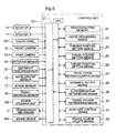
- FIG. 5 shows the system for inputting and outputting information to and from the control unit 20 that functions as the assist information output means of the present invention.
- the control unit 20 is provided with an input system for receiving information from the touch panel 10T, the front camera 12, the rear camera 13, the steering sensor 14, the shift position sensor 15, the accelerator sensor 16, the brake sensor 17, and the travel distance sensor 18; and an output system for outputting control signals to the monitor 10, the speaker 11, the power steering unit PS, the change speed mechanism T, and the brake device BK.
- the control unit 20 is provided with an input/output interface 21 for inputting and outputting information, and a microprocessor CPU for processing information from the input/output interface 21.
- Semiconductor memory 22, an image processing means 23, a parking position setting means 24, a travel course setting means 25, a target position setting means 26, a travel course information display means 27, a guidance output means 28, a superimposition determining means 29, a travel course determining means 30, an auxiliary control means 31 which is also referred to as driving assisting means, and a travel course update means 32 are each connected to a data bus of the microprocessor CPU. While the control system requires a control bus, an address bus, etc. besides the data bus in this control system, the drawing does not show the control bus, the address bus, or the interfaces in the interest of simplifying the drawing.
- the image processing means 23 processes the image information from the front camera 12 or the rear camera 13 in real time to display the information on the monitor 10, and at the same time synthesizes and displays, on the monitor 10, the parking area 45 (see FIG. 8 ), bar-shaped (line-shaped) guide information G (a broader concept covering the plurality of guide information described hereinafter; see FIG. 6 ), an indicator H indicated by a rectangular frame whose size is sufficient to accommodate the bar-shaped guide information G, and other information described hereinafter.
- the parking position setting means 24 sets a parking position P based on human operation of the touch panel 10T or of vehicle movement.
- the travel course setting means 25 calculates a travel course C for introducing the vehicle B into the parking position P based on the parking position P and the current position of the vehicle B.
- the target position setting means 26 sets a plurality of target positions along the travel course C.
- the travel course information display means 27 displays the guide information G corresponding to the target position, and the indicator H and other information for determining the position of the vehicle B
- the guidance output means 28 outputs information necessary for moving the vehicle B along the travel course C.
- the superimposition determining means 29 determines whether the guide information G and the indicator H are in a overlapping positional relationship on the monitor 10.
- the travel course determining means 30 determines the positional relationship between the vehicle B and the travel course C based on the information from the travel distance sensor 18 and the steering sensor 14.
- the auxiliary control means 31 performs control for correcting the driving operations of the driver to the correct direction when the vehicle B is introduced into the parking position P.
- the travel course update means 32 calculates an error value between the travel course C and the vehicle B from the positional relationship between the guide information G and the indicator H when the vehicle is at rest, and performs a routine for recalculating the travel course for introducing the vehicle B in the current stop position into the parking position P when the error exceeds a predetermined value.
- the parking assist device of the present invention has the processing system shown in FIG. 5 .
- the image processing means 23, the parking position setting means 24, the travel course setting means 25, the target position setting means 26, the travel course information display means 27, the guidance output means 28, the superimposition determining means 29, the travel course determining means 30, the auxiliary control means 31, and the travel course update means 32 are envisaged to be implemented by software deployed in the semiconductor memory 22 or other devices, any one or more of these may also be implemented by logic or other hardware, or by a combination of software and hardware.
- the vehicle B When parking the vehicle B in the parking position P (see FIGS. 7 and 8 ), the vehicle B is stopped in the position (a position imaged by the front camera 12) in which the parking position P is displayed on the monitor 10.
- the driver subsequently specifies a parking position P on the monitor 10, whereby the control unit 20 calculates the positional relationship between the parking position P and the current position of the vehicle B, calculates the optimal travel course C for introducing the vehicle B into the parking position P, and displays the necessary assist information for moving the vehicle B along the travel course C on the monitor 10.
- the driver moves the vehicle along the travel course C and parks the vehicle in the parking position P simply by moving the vehicle B in accordance with the assist information displayed on the monitor 10, or a voice message from the speaker 11.
- control unit 20 automatically performs auxiliary control for causing the correct operations to be performed, and when the vehicle B is stopped in an incorrect position during introduction, the control unit 20 performs a routine for recalculating and updating the travel course for introducing the incorrectly positioned vehicle B into the parking position P.
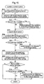
- FIG. 14 An overview of such routines performed by the control unit 20 can be shown by the flowchart shown in FIG. 14 .
- the vehicle B is stopped in the position in which the parking position P is displayed on the monitor 10, as shown in FIG. 7 .
- a garage parking button 41, a parallel parking button 42, and a cancel button 43 are displayed on the monitor 10, and the garage parking mode is selected by the driver touching a finger to the garage parking button 41 (step #101).
- the mode for introducing the vehicle B into the parking position P in an orientation parallel to the orientation in which the vehicle B is stopped is referred to as parallel parking
- the mode for introducing the vehicle B into the parking position in an orientation orthogonal to the orientation in which the vehicle B is stopped is referred to as garage parking.
- the parallel parking button 42 is actuated, the travel course C for introducing the vehicle B into the parking position P is set, the assist information is displayed on the monitor 10 by the same processing as in the aforementioned garage parking mode, a message is outputted as assist information from the speaker 11, and garage parking can be performed based on the provided information.
- buttons 44 and the outline of a parking area 45 for specifying the parking position P are displayed on the monitor 10, as shown in FIG. 8 .
- the parking area 45 is moved to the parking position P on the monitor 10, and operating an OK button 46 with the parking area 45 set to the correct position fixes the position of the parking area 45, and the position encompassed by the parking area 45 is set to be the parking position P (step #102).
- This processing is executed by the parking position setting means 24, and the size of the parking area 45 is set based on the total length and width of the vehicle B.
- the cursor buttons 44 and the parking area 45 are displayed on the monitor 10 by the image processing means 23.
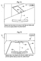
- the imaging lens used in the front camera 12 is a fixed-focus lens, and the imaging direction is fixed to the vehicle B. And since the level of the imaged ground surface coincides with the ground contact level of the front wheels 1 and rear wheels 2, the relative distance between a particular position on the ground surface displayed on the monitor and the vehicle B can be obtained by processing the image.
- the image processing means 23 with table data, parameters, or the like for acquiring the distance of the vehicle B from a position displayed on the monitor 10, the shape of the display is changed to be consistent with the perspective created by the imaging lens when the parking area 45 is moved as previously described, the position of the parking position P (parking area 45) in relation to the vehicle B can be identified, and the positional relationship or distance between the parking position P and the vehicle B can be acquired with relatively high precision.
- a camera having the same capabilities as the front camera 12 is also used as the rear camera 13.
- the parking area 45 may be aligned with the parking position not only by selecting settings with a cursor, but also by moving the vehicle B.
- the travel course C shown in FIG. 6 for introducing the vehicle B into the parking position P is computed based on the acquired information (step #103), the target positions are set on the travel course C, and the orientation of the vehicle B in each target position is computed (step #104).
- These routines are executed by the travel course setting means 25, and the travel course setting means 25 computes the optimum travel course C for introducing the vehicle B into the parking position P from the positional relationship or distance between the parking position P and the current position of the vehicle B based on the total length and width, wheelbase, turning characteristics, and other data of the vehicle B.
- the travel course C is the path in which the center of the rear wheel axle moves.
- the travel course C thus computed and as seen from above has the shape shown in FIG. 6 .
- Four target positions are set on the travel course C, and guide information G1 through G4 is set for the four target positions.
- the guide information G the first and second guide information G1, G2 is displayed on the ground surface imaged by the front camera 12 during a forward movement of the vehicle B, and the third and fourth guide information G3, G4 is displayed on the ground surface imaged by the rear camera 13.
- the guide information G1 through G4 is in the form of lines, and the longitudinal direction of the lines of guide information G1 through G4 coincides with the width (left-right) direction of the vehicle B.
- the vehicle B is placed in the correct orientation in the correct stop position by stopping the vehicle B such that the guide information is superimposed on the indicator H displayed on the monitor 10 to match G1 and G2, of the guide information G1 - G4, with the front end of the vehicle B on the monitor 10, and to match G3 and G4 with the rear end of the vehicle B on the monitor 10.
- the initial (first) guide information G1 corresponding to the target position is displayed in red on the ground surface on the monitor 10, as shown in FIG. 9 (step #105) and the yellow frame-shaped indicator H elongated in the width direction of the vehicle B so as to encompass the guide information G1 is displayed at the lower end of the monitor 10 (the side nearest the vehicle B) at the same time.
- This process is implemented by the image processing means 23 synthesizing the guide information G generated by the target position setting means 26 with the image from the front camera 12.
- the aforementioned colors are not limiting insofar as the guide information G1 and the indicator H are each displayed in different colors.
- the guide information G on the ground surface displayed on the monitor 10 must be displayed to be moving toward the vehicle B along with the ground surface, and this processing is performed by the image processing means 23.
- a travel course display button 47 is displayed on the monitor 10.
- the travel course C shown in the diagram is displayed on the ground surface in red (the travel course C is not displayed when the travel course display button 47 is not operated).
- a voice message saying "please move until the red line display enters the yellow frame" is outputted from the speaker 11 (step #106). While these routines are executed by the guidance output means 28, an output may also be configured such that the message is displayed on the monitor 10 at the same time the voice message is output.
- the movement direction is determined by the information from the shift position sensor 15, the steering amount is acquired by the steering sensor 14, and the traveling distance of the vehicle B is acquired by the travel distance sensor 18.
- the travel course determining means 30 determines whether the vehicle B is moving along the travel course C.
- the auxiliary control means 31 controls at least one of the change speed mechanism T, the power steering unit PS, and the brake device BK to perform auxiliary control so that the vehicle B travels to a position closer to the correct travel course C (step #200).
- Step #200 is set as an auxiliary control routine (sub-routine).
- a signal from the steering sensor 14 is compared with a target steering angle in the current position of the vehicle B, and when the steering angle is smaller or larger than a reference angle region (dead zone) set about a target steering angle, the control unit 20 performs correction control for operating the power steering unit PS in the direction of the target steering angle, whereby the vehicle is steered to approximate the correct steering angle. Correction control is not performed when the steering angle is within the reference region that is set based on the target steering angle (steps #201 through #204).
- the travel speed of the vehicle B is acquired and compared with a target speed in the current position of the vehicle B, and when the travel speed of the vehicle B is higher or lower than a reference speed region (dead zone) that is set about a target speed in the current position of the vehicle B, the control unit 20 controls the change speed mechanism T and performs correction control for changing speed toward the target speed, whereby the correct travel speed is obtained. Correction control is not performed when the travel speed of the vehicle B is within the reference speed region for the current position of the vehicle B (steps #205 through #208).
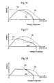
- the change in speed when this speed control is performed can be shown as indicated by the graph in FIG. 16 . That is, a target speed Vx is set so that the speed is reduced smoothly as the vehicle approaches the target position (guide information G), so that even in a case in which speed Vb is reached without correction control, performing control that follows the target speed Vx allows the speed to be reduced as the vehicle approaches the target position, and the speed to be brought to zero at the target position, as indicated by the speed Va.
- a control configuration is set so as to stop the vehicle at the target position, and when the speed is controlled in this manner, the travel speed of the vehicle B is maintained at the target speed through brake control. It is also possible to maintain the travel speed of the vehicle B at the target speed by giving priority to control of at least one of the change speed mechanism T and the speed of the engine E over operation of the accelerator pedal 7.
- the control shown in the graph of FIG. 17 may also be used in lieu of the speed control described above.
- a target speed Vx is set so that the speed is incrementally reduced as the vehicle approaches the target position (guide information G). Even in a case in which speed Vb is reached without the correction control, performing control that follows the target speed Vx allows the speed to be reduced as the vehicle approaches the target position, as indicated by the speed Va. A control configuration is thus possible where the vehicle is stopped in the target position.
- the travel speed and the current position of the vehicle B are then acquired, and the travel speed and the current position of the vehicle B are compared, and a determination is made based on the signal from the brake sensor 17 as to whether the brake pedal 8 is being operated.
- the control unit 20 performs correction control for braking of the brake device BK, whereby the correct travel speed is obtained by applying a braking force based on the relative position of the vehicle B and the target position. Correction control is not performed when the speed is lower than the speed that is set based on the relative positions of the vehicle B and the target position (steps #209 through #213).
- the speed change that occurs when this braking control is performed can be shown by the graph in FIG. 18 . That is, the target speed Vx is set so that the speed decreases as the vehicle approaches the target position (guide information G). When the driver is operating the brake pedal 8, and the speed exceeds the target speed Vx, then the speed can be brought to zero at the target position by applying appropriate braking force even when the speed becomes Vb when correction control is not performed. A control configuration is thus possible where the vehicle is stopped in the target position.
- a voice message may be outputted to induce the correct operations, or a message may be displayed on the monitor 10.
- an auxiliary control routine step #200
- this auxiliary control routine is always executed when the vehicle B is moved so as to be introduced into the parking position P.
- the vehicle B is then moved forward, and stopped in the position (overlap position) in which the first guide information G1 is surrounded by the indicator H as shown in FIG. 10 , whereby the guide information G1 surrounded by the indicator H changes from red to green.
- the guide information G1 is then erased from the monitor 10, the next (second) guide information G2 is newly displayed on the monitor 10, and a voice message saying "please turn the wheel all the way to the left and drive until the red line display enters the yellow frame" is outputted from the speaker 11 (this message may also be displayed on the monitor 10) (steps #107 through #112).
- the error is calculated from the positional relationship between the guide information G1 and the indicator H, and when the error exceeds a predetermined value, the travel course is recalculated, and the target position is then updated so as to reduce the effect of the error on the target parking position (step #111).
- determining whether the guide information G and the indicator H are superimposed on each other entails continually computing the relative positions from the travel direction and such values as the travel distance of the vehicle B, and drawing and erasing the guide information G1 on the image of the front camera 12 according to the calculation results.
- the guidance output means 28 erases the guide information G1 and newly displays the guide information G2. While FIG. 10 shows the travel course C being displayed while the guide information G1 and the indicator H coincide on the monitor 10, these are not displayed at the same time.
- the display sequence may be that the guide information G1 and the indicator H coincide, after which the guide information G1 is erased, and the travel course C is then displayed immediately after the guide information G1 is erased. This display sequence is the same in FIGS. 11 and 13 described hereinafter.
- the vehicle B when, after the second guide information G2 is displayed, the vehicle B is moved to and stopped in the position (superimpose position) in which the second guide information G2 is surrounded by the indicator H, the guide information G2 surrounded by the indicator H, as shown in FIG. 11 , is changed from red to green and then erased from the monitor 10, and the message "please set the shift lever to the reverse position" is outputted from the speaker 11 as shown in FIG. 11 (the message may also be simultaneously displayed on the monitor 10).
- the shift lever 6 is set in the reverse position, whereby an image from the rear camera 13 is displayed on the monitor 10 as shown in FIG. 12 , the next (third) guide information G3 f is displayed on the monitor 10, and the message “please turn the wheel all the way to the right and drive until the red line display enters the yellow frame” is outputted from the speaker 11 (the message may also be simultaneously displayed on the monitor 10).
- the position By moving the vehicle B while the steering wheel 4 is turned according to the message, the position (superimpose position) is reached in which next guide information G3 displayed on the monitor 10 is surrounded by the indicator H as shown in FIG. 13 , at which time the vehicle B is stopped.
- the message "please return the wheel to the neutral position and drive until the red line display enters the yellow frame” is outputted from the speaker 11 (the message may also be simultaneously displayed on the monitor 10).
- the position By driving vehicle B in reverse while turning the steering wheel 4 in accordance with the message, the position (superimpose position (not shown)) is reached in which the final (fourth) guide information G4 displayed on the monitor 10 is surrounded by the indicator H.
- the message "parking complete” is outputted from the speaker 11 (the message may also be simultaneously displayed on the monitor 10), and parking is completed.
- the vehicle B is situated within the parking area 45 displayed on the monitor 10.
- the vehicle B is sometimes stopped in an inappropriate position by an inappropriate operation performed by the driver while the vehicle B is being introduced into the parking position P in the manner described above.
- the travel course update means 32 executes the routine shown in step #111, whereby the travel course C is recalculated, and a new target position is set for the travel course C.
- the vehicle B may stop in a position that is slightly past the position of the first guide information G1, as shown in FIG. 19 .
- a new travel course C' is calculated in place of the correct travel course C by using image processing to assess the positioning error between the guide information G and the indicator H and to assess the error in the orientation of the vehicle B, a new target position is set with respect to the travel course C', and guide positions G2', G3' are set in accordance with the target position.
- a message is also presented as needed for the new guide positions G2', G3'. Consequently, even when the vehicle B is stopped in an incorrect position during introduction of the vehicle B into the parking position, the vehicle B can be introduced into the parking position P simply by operating according to the information displayed on the monitor 10 and the messages outputted from the speaker 11.
- the driver specifies the parking position P on the monitor 10 in which an image captured by the front camera 12 is displayed, and after a parking mode is selected, the travel course C for introducing the vehicle B into the parking position P is automatically calculated, and a plurality of target positions on the travel course C and the orientation of the vehicle B in the target positions are established.
- While a plurality of target positions may be set when the vehicle B is introduced into the parking position P, since only the guide information G alone, presented in the form of a line, are displayed on the ground surface on the monitor 10 in correspondence with the target positions for movement of the vehicle and, at the same time, the frame-shaped indicator H is displayed on the monitor 10, and messages necessary for movement of the vehicle B are outputted as a voice or text information, a simple moving operation is possible where the driver moves the vehicle B by following the messages until it reaches the position (superimpose position) where the guide information G in the form of a line is surrounded by a frame-shaped indicator H.
- the vehicle B can be moved along the correct travel course C and introduced into the parking position P while the inconvenience of recognizing a wrong target is prevented.
- the inconvenience of having the vehicle B significantly deviating from the travel course C can be prevented through correction control during introduction of the vehicle B into the parking position P even when the steering, acceleration, and braking are somewhat inappropriate.
- the vehicle B can be correctly introduced into the parking position P by calculating a new travel course C' when the vehicle B is stopped and by displaying guide information on the monitor 10 that is in accordance with the travel course C' thus calculated.
- the parking assist device is capable of providing parking assist regardless of the vehicle size.
- parking can be performed by a smooth operation when the present invention is used in an automobile such as a large truck, which has a structure in which the area behind the vehicle is difficult to confirm.
- an auxiliary monitor may be provided behind the driver seat to enable information to be confirmed when the vehicle is moving in reverse, for example, and even more precise parking assist can be provided by displaying the same information in the auxiliary monitor as in the main monitor.
Abstract
Description
- The present invention relates to a parking assist device that is provided with a monitor for displaying a captured image from a camera provided to a vehicle, and assist information output means for displaying assist information during parking on the monitor.
- Conventional technologies relating to a parking assist device having the kind of configuration described above includes one disclosed in
Patent Document 1. In the device disclosed inPatent Document 1, when the shift lever is placed in the reverse position during parallel parking, steering initiation guide lines, vehicle width guide lines, and vehicle trajectory guide lines are superimposed on a camera image of the area to the rear of the vehicle and are displayed on a monitor. The vehicle is then driven in reverse, the vehicle is stopped when the steering initiation guide lines reach a target point, and the steering wheel is turned. A steering amount guide mark is moved by the turning of the steering wheel in this manner, and after the steering wheel is turned until the steering amount guide mark reaches the target point, the vehicle can be properly advanced into the parking space by driving the vehicle in reverse. - A technology relating to a parking assist device configured as described above is disclosed in
Patent Document 2, which discloses performing a portion of the steering automatically to guide a vehicle into a parking position. In the technology disclosed inPatent Document 2, control is initiated with the vehicle body in a specific position with respect to a parking position, whereby the steering wheel is automatically turned by automatic steering control. As the driver moves the vehicle very slowly, the vehicle is moved into a traveling direction switching position. When the vehicle is in the traveling direction switching position, the front wheels are already steered appropriately for moving the vehicle into the parking position. The driver can then move the vehicle into the parking position by driving the vehicle in reverse. - [Patent Document 1] Japanese Laid-open Patent Application No.
2001-55099 FIGS. 2 ,3 ) - [Patent Document 2] Japanese Laid-open Patent Application No.
2000-335436 FIGS. 1 through 3 ) - When the operations for introducing an automobile into a parking position are considered, the vehicle must be moved as precisely as possible along a path of introduction into the parking position. Reliable operation is desired particularly when parking is performed by a driver who is inexperienced in driving technique, or when the parking space is narrow. The aforementioned technologies disclosed in
Patent Documents - However, even in a case in which the image from a camera is displayed on a monitor as described in
Patent Document 1, the vehicle is stopped when the steering initiation guide line reaches the target point displayed on the monitor, and the steering wheel is turned, the vehicle sometimes cannot be properly introduced into the parking position when the vehicle is stopped in a position other than the optimal stopping position due to an incorrect stop timing. Similarly, the vehicle sometimes cannot be properly introduced into the parking position if the steering wheel is turned by an incorrect amount even when the vehicle is stopped in the correct stopping position. Particularly when the vehicle is introduced into a parking position on an inclined ground surface, the vehicle may move past the appropriate stopping position before stopping. - A technology such as the one disclosed in
Patent Document 2, in which a portion of the operation for introducing the vehicle into the parking position is performed automatically, relieves the driver of the task of operating the vehicle. However, in the technology disclosed inPatent Document 2, the vehicle must be set in the correct position in an initial stage for initiating control. - From the perspective of the driver, the information necessary for parking must be acquired via the monitor the steering wheel must be properly operated, and the stopping position must be correct when the vehicle is introduced into the parking position as described in
Patent Document 1. But, with the technology in which operations are automatically controlled, the vehicle must be set in the correct position in an initial stage, and this setting is difficult to perform.
EP-A-1 591 315 discloses a parking assist apparatus for a vehicle according to the preamble ofclaim 1. Further,JP 2005 313 775 A claim 1.
JP 2004 352 120 A
JP 2003 191 809 A
DE 103 38 255 A1 refers to guiding of a vehicle from a reference position to a target parking position using an icon display of a steering wheel and a voice guidance from a speaker. Herein, a fore-and aft direction guide line 41 a for positioning a vehicle in a fore-and aft direction and a transverse direction guide line 41 b for positioning a vehicle in a transverse direction is mentioned. Both guide lines 41a, 41b are provided to park the vehicle with ease in a reference position for determining a target parking position.
However, none of the documentsJP 2004 352 120 A JP 2003 191 809 A DE 103 38 255 A1 provides the features of the characterizing portion ofclaim 1 or the feature of superimposing guide information corresponding to the target position over a ground surface displayed on said monitor. - An object of the present invention is to logically configure a device for correctly introducing a vehicle into a parking position even when driving operations for introducing the vehicle into the parking position are inadequate.
- This object is achieved by the parking assist device as defined in
claim 1. Further developments are set out in the dependent claims. - With the configuration of the parking assist device of
claim 1, the vehicle can be moved along the travel course and introduced into the parking position by turning the steering wheel and moving the vehicle so as, for example, to superimpose the guide information displayed on the ground surface on the monitor, and the indicator displayed on the monitor. The driving assisting means also corrects the driving operations when the steering wheel is operated incorrectly, the position of the guide information on the travel course is inaccurate, or other such conditions occur when the vehicle is moved along the travel course. As a result, the device is effectively configured to correctly introduce the vehicle into the parking position even when the driving operations for introducing the vehicle into the parking position are inaccurate. - In the present invention, said assist information output means may include travel course update means for calculating a positional error between said travel course and the vehicle based on a positional relationship between said guide information and the indicator, or a positional relationship between said target position and the vehicle, and newly calculating a travel course for introducing the vehicle from a current position to said parking position based on the positional error.
- With this configuration, since the travel course is newly calculated based on a positional error calculated from the positional relationship between the guide information and the indicator, or the positional relationship between the target position and the vehicle, the error is not compounded through movement of the vehicle without resetting the travel course, and the vehicle can be correctly introduced into the parking position.
- The present invention may further comprise a steering unit for steering a steered wheel of the vehicle based on operation of a steering wheel; and a steering sensor for measuring a steering angle of said steered wheel; wherein said driving assisting means may control said steering unit and correct the steering angle of said steered wheel to a correct direction when a steering angle from the steering sensor differs from a target value that is set based on said travel course.
- With this configuration, when the movement of the vehicle differs from the steering angle measured by the steering sensor, the steering unit is controlled and the steering angle of the steered wheels is adjusted to the correct direction, whereby an excess or deficiency of the steering angle can be corrected, and the vehicle can be moved in the correct travel course or a travel course that is close to the correct travel course.
- The present invention may further comprise a brake unit for applying a braking force to a wheel of said vehicle based on a brake pedal operation; and a brake sensor for detecting operation of said brake pedal; wherein said driving assisting means may perform braking control of said brake unit when said vehicle approaches a stopping position set in said travel course while said brake sensor detects that the brake pedal is being operated.
- With this configuration, when the brake sensor detects that the driver is operating the brake pedal when the vehicle is near the stopping position, the driving assisting means controls the braking of the brake unit, whereby the vehicle can be prevented from overrunning the stopping position.
- The present invention may further comprise a speed setting unit for setting a travel speed of the vehicle based on operation of an accelerator operation member; and an accelerator sensor for measuring an amount of operation of said accelerator operation member; wherein said driving assisting means may control said speed setting unit to reduce a travel speed of the vehicle to a value less than a travel speed set by said accelerator operation member when said vehicle approaches a stopping position set in said travel course.
- With this configuration, the driving assisting means controls the speed setting unit when the vehicle is near the stopping position, whereby the travel speed of the vehicle is reduced to a value less than the travel speed set by the accelerator operation member, and the vehicle can be prevented from overrunning the stopping position.
- In the present invention, said guide information may be displayed on said monitor in a bar form, and said indicator may be displayed on said monitor as a rectangular frame in which said guide information is accommodated
- With this configuration, the vehicle can be moved along the travel course and introduced into the parking position by driving the vehicle so that the bar-form guide information is accommodated within the guide information composed of a rectangular frame.
- In the present invention, said assist information output means may set a plurality of target positions located at intermediate positions within said travel course.
- With this configuration, the vehicle can be introduced into the parking position by driving the vehicle along a plurality of target positions.
- In the present invention, said assist information output means may set four target positions on said travel course and may set guide information for the four target positions when providing assistance during garage parking in which the vehicle is introduced into a parking position in an orientation orthogonal to the stopping orientation.
- With this configuration, the vehicle can be moved by following the guide information that is set to four target positions.
- In the present invention, said camera may comprise a front camera provided to a front end of said vehicle, and a rear camera provided to a rear end of said vehicle; and guide information that is set for a first and second of said four target positions may be displayed on a ground surface image captured by said front camera during forward travel of said vehicle; and guide information that is set for a third and fourth of said four target positions may be displayed on a ground surface image captured by said rear camera during reverse travel of said vehicle.
- With this configuration, the vehicle can be moved by following the guide information of the first and second target positions displayed on the ground surface image captured by the front camera when the vehicle is moved forward, and the vehicle can be moved by following the guide information of the third and fourth target positions displayed on the ground surface image captured by the rear camera when the vehicle is moved in reverse.
- In the present invention, said guide information and said indicator may be displayed in different colors on said monitor.
- The guide information and the indicator can thereby be distinguished by display color on the monitor.
-
-
FIG. 1 is a perspective view in which a portion of an automobile is cut away; -
FIG. 2 is a perspective view showing the vehicle front; -
FIG. 3 is a diagram showing the region forwardly of the driver seat; -
FIG. 4 is a plan view diagrammatically showing the structure of the vehicle; -
FIG. 5 is a block circuit diagram of the control system; -
FIG. 6 is a diagram showing the positions of the guide information and the travel course for introducing the vehicle into the parking position; -
FIG. 7 shows the parking position displayed on the monitor; -
FIG. 8 shows the monitor display when the parking position is set; -
FIG. 9 shows the initial guide information displayed on the monitor; -
FIG. 10 shows the monitor in which the indicator and the initial guide information are superimposed on the display; -
FIG. 11 shows the monitor in which the indicator and the second guide information are superimposed on the display; -
FIG. 12 shows the monitor in which the third guide information is displayed; -
FIG. 13 shows the monitor in which the indicator and the third guide information are superimposed on the display; -
FIG. 14 is a flowchart showing the parking assist routines; -
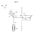
FIG. 15 is a flowchart showing the auxiliary control routines; -
FIG. 16 is a diagram showing the target speed and the change in speed due to speed change at the time of correction control; -
FIG. 17 is a diagram showing the target speed and the change in speed due to a speed change at the time of correction control; -
FIG. 18 is the target speed and the change in speed due to braking at the time of correction control; and -
FIG. 19 is a diagram showing the initial travel course and the newly set travel course. - Embodiments of the present invention will be described next with reference to the drawings.
(Overall structure) As shown inFIGS. 1 through 4 , an automobile has adriver seat 3 and asteering wheel 4 are provided inside the cabin of a vehicle B that has front wheels 1 (an example of steered wheels) andrear wheels 2. Apanel 5 having gauges is disposed at the front of the cabin, and ashift lever 6 for effecting a speed change is disposed beside thedriver seat 3. - The
steering wheel 4 is coupled to a power steering unit PS that performs a powered steering to transmit a rotational operating force to thefront wheels 1. An engine E and a change speed (or transmission) mechanism T (an example of the speed setting unit) composed of a torque converter, a CVT, or the like for transmitting the drive force from the engine E to thefront wheels 1, after changing the speed of the drive force, are disposed at the front of the vehicle. Anaccelerator pedal 7 as an accelerator operation member for controlling the travel speed, and abrake pedal 8 for operating a brake device BK of thefront wheels 1 andrear wheels 2, and applying braking force to thefront wheels 1 andrear wheels 2, are disposed next to each other in the vicinity of thedriver seat 3. - A
monitor 10 is provided in which atouch panel 10T is formed on the display surface in an upper position of a console near thedriver seat 3, and aspeaker 11 is provided to the casing for themonitor 10. (It is possible to use thespeaker 11 provided to thepanel 5, or a speaker provided on the inside of a door.) Afront camera 12 is provided to the front end of the vehicle B, and arear camera 13 is provided to the rear end of the vehicle B. While themonitor 10 is a liquid crystal monitor provided with a backlight, it may also be a plasma display or a CRT display. A pressure-sensitive touch panel or an electrostatic touch panel is used as thetouch panel 10T, and thetouch panel 10T outputs the touch position of a finger, etc. as location data. Themonitor 10 may also be used to display GPS navigation data. - Each of the
front camera 12 and therear camera 13 houses a CCD imaging device and is configured to output captured information as moving image information. Thefront camera 12 is set so that the ground surface in front of the vehicle B is the main imaging area, and therear camera 13 is set so that the ground surface behind the vehicle B is the main imaging area. Each camera has sufficient performance to output moving image in real time. - A
steering sensor 14 for measuring a steering direction and a steering amount is provided to the operation system of thesteering wheel 4, and ashift position sensor 15 for determining a shift position is provided to the operation system of theshift lever 6. Anaccelerator sensor 16 for measuring the amount of accelerator pedal operation is provided to the operation system of theaccelerator pedal 7, and abrake sensor 17 for detecting the operation of the brake pedal is provided to the operation system of thebrake pedal 8. - A
travel distance sensor 18 for measuring the travel distance of the vehicle B based on the number of rotation of the drive train is provided to the change speed mechanism T. A photo-interrupter or pickup-type sensor for measuring the number of rotation of at least one of thefront wheels 1 and therear wheels 2 may be used as thetravel distance sensor 18. A control unit 20 (an example of the assist information output means) as an ECU for performing travel control is disposed in the central part of the vehicle B. -
FIG. 5 shows the system for inputting and outputting information to and from thecontrol unit 20 that functions as the assist information output means of the present invention. Thecontrol unit 20 is provided with an input system for receiving information from thetouch panel 10T, thefront camera 12, therear camera 13, thesteering sensor 14, theshift position sensor 15, theaccelerator sensor 16, thebrake sensor 17, and thetravel distance sensor 18; and an output system for outputting control signals to themonitor 10, thespeaker 11, the power steering unit PS, the change speed mechanism T, and the brake device BK. - The
control unit 20 is provided with an input/output interface 21 for inputting and outputting information, and a microprocessor CPU for processing information from the input/output interface 21.Semiconductor memory 22, an image processing means 23, a parking position setting means 24, a travel course setting means 25, a target position setting means 26, a travel course information display means 27, a guidance output means 28, asuperimposition determining means 29, a travelcourse determining means 30, an auxiliary control means 31 which is also referred to as driving assisting means, and a travel course update means 32 are each connected to a data bus of the microprocessor CPU. While the control system requires a control bus, an address bus, etc. besides the data bus in this control system, the drawing does not show the control bus, the address bus, or the interfaces in the interest of simplifying the drawing. - The image processing means 23 processes the image information from the
front camera 12 or therear camera 13 in real time to display the information on themonitor 10, and at the same time synthesizes and displays, on themonitor 10, the parking area 45 (seeFIG. 8 ), bar-shaped (line-shaped) guide information G (a broader concept covering the plurality of guide information described hereinafter; seeFIG. 6 ), an indicator H indicated by a rectangular frame whose size is sufficient to accommodate the bar-shaped guide information G, and other information described hereinafter. The parking position setting means 24 sets a parking position P based on human operation of thetouch panel 10T or of vehicle movement. The travel course setting means 25 calculates a travel course C for introducing the vehicle B into the parking position P based on the parking position P and the current position of the vehicle B. The target position setting means 26 sets a plurality of target positions along the travel course C. The travel course information display means 27 displays the guide information G corresponding to the target position, and the indicator H and other information for determining the position of the vehicle B on themonitor 10. - The guidance output means 28 outputs information necessary for moving the vehicle B along the travel course C. The
superimposition determining means 29 determines whether the guide information G and the indicator H are in a overlapping positional relationship on themonitor 10. The travelcourse determining means 30 determines the positional relationship between the vehicle B and the travel course C based on the information from thetravel distance sensor 18 and thesteering sensor 14. The auxiliary control means 31 performs control for correcting the driving operations of the driver to the correct direction when the vehicle B is introduced into the parking position P. The travel course update means 32 calculates an error value between the travel course C and the vehicle B from the positional relationship between the guide information G and the indicator H when the vehicle is at rest, and performs a routine for recalculating the travel course for introducing the vehicle B in the current stop position into the parking position P when the error exceeds a predetermined value. The parking assist device of the present invention has the processing system shown inFIG. 5 . - While the image processing means 23, the parking position setting means 24, the travel course setting means 25, the target position setting means 26, the travel course information display means 27, the guidance output means 28, the
superimposition determining means 29, the travelcourse determining means 30, the auxiliary control means 31, and the travel course update means 32 are envisaged to be implemented by software deployed in thesemiconductor memory 22 or other devices, any one or more of these may also be implemented by logic or other hardware, or by a combination of software and hardware. - When parking the vehicle B in the parking position P (see
FIGS. 7 and8 ), the vehicle B is stopped in the position (a position imaged by the front camera 12) in which the parking position P is displayed on themonitor 10. The driver subsequently specifies a parking position P on themonitor 10, whereby thecontrol unit 20 calculates the positional relationship between the parking position P and the current position of the vehicle B, calculates the optimal travel course C for introducing the vehicle B into the parking position P, and displays the necessary assist information for moving the vehicle B along the travel course C on themonitor 10. The driver moves the vehicle along the travel course C and parks the vehicle in the parking position P simply by moving the vehicle B in accordance with the assist information displayed on themonitor 10, or a voice message from thespeaker 11. - When the operations of the driver are incorrect during introduction of the vehicle B into the parking position P, the
control unit 20 automatically performs auxiliary control for causing the correct operations to be performed, and when the vehicle B is stopped in an incorrect position during introduction, thecontrol unit 20 performs a routine for recalculating and updating the travel course for introducing the incorrectly positioned vehicle B into the parking position P. - An overview of such routines performed by the
control unit 20 can be shown by the flowchart shown inFIG. 14 . Using garage parking as an example, the vehicle B is stopped in the position in which the parking position P is displayed on themonitor 10, as shown inFIG. 7 . In this state, agarage parking button 41, aparallel parking button 42, and a cancelbutton 43 are displayed on themonitor 10, and the garage parking mode is selected by the driver touching a finger to the garage parking button 41 (step #101). One touches the cancelbutton 43 to cancel a parking assist. - In the parking assist device of the present invention, the mode for introducing the vehicle B into the parking position P in an orientation parallel to the orientation in which the vehicle B is stopped is referred to as parallel parking, and the mode for introducing the vehicle B into the parking position in an orientation orthogonal to the orientation in which the vehicle B is stopped is referred to as garage parking. When the
parallel parking button 42 is actuated, the travel course C for introducing the vehicle B into the parking position P is set, the assist information is displayed on themonitor 10 by the same processing as in the aforementioned garage parking mode, a message is outputted as assist information from thespeaker 11, and garage parking can be performed based on the provided information. - As previously mentioned, after the garage parking mode is selected, four
cursor buttons 44 and the outline of aparking area 45 for specifying the parking position P are displayed on themonitor 10, as shown inFIG. 8 . When the driver touches any of thecursor buttons 44 when the display is in this state, theparking area 45 is moved to the parking position P on themonitor 10, and operating anOK button 46 with theparking area 45 set to the correct position fixes the position of theparking area 45, and the position encompassed by theparking area 45 is set to be the parking position P (step #102). This processing is executed by the parking position setting means 24, and the size of theparking area 45 is set based on the total length and width of the vehicle B. Thecursor buttons 44 and theparking area 45 are displayed on themonitor 10 by the image processing means 23. - Since a wide-angle lens is used as the imaging lens (not shown) of the
front camera 12, the perspective is exaggerated, and linear objects appear curved. The imaging lens used in thefront camera 12 is a fixed-focus lens, and the imaging direction is fixed to the vehicle B. And since the level of the imaged ground surface coincides with the ground contact level of thefront wheels 1 andrear wheels 2, the relative distance between a particular position on the ground surface displayed on the monitor and the vehicle B can be obtained by processing the image. Thus, by providing the image processing means 23 with table data, parameters, or the like for acquiring the distance of the vehicle B from a position displayed on themonitor 10, the shape of the display is changed to be consistent with the perspective created by the imaging lens when theparking area 45 is moved as previously described, the position of the parking position P (parking area 45) in relation to the vehicle B can be identified, and the positional relationship or distance between the parking position P and the vehicle B can be acquired with relatively high precision. A camera having the same capabilities as thefront camera 12 is also used as therear camera 13. - The
parking area 45 may be aligned with the parking position not only by selecting settings with a cursor, but also by moving the vehicle B. - After the relative distance between the parking position P and the current stop position of the vehicle B is acquired, the travel course C shown in
FIG. 6 for introducing the vehicle B into the parking position P is computed based on the acquired information (step #103), the target positions are set on the travel course C, and the orientation of the vehicle B in each target position is computed (step #104). These routines are executed by the travel course setting means 25, and the travel course setting means 25 computes the optimum travel course C for introducing the vehicle B into the parking position P from the positional relationship or distance between the parking position P and the current position of the vehicle B based on the total length and width, wheelbase, turning characteristics, and other data of the vehicle B. The travel course C is the path in which the center of the rear wheel axle moves. - The travel course C thus computed and as seen from above has the shape shown in
FIG. 6 . Four target positions are set on the travel course C, and guide information G1 through G4 is set for the four target positions. Among the guide information G, the first and second guide information G1, G2 is displayed on the ground surface imaged by thefront camera 12 during a forward movement of the vehicle B, and the third and fourth guide information G3, G4 is displayed on the ground surface imaged by therear camera 13. - The guide information G1 through G4 is in the form of lines, and the longitudinal direction of the lines of guide information G1 through G4 coincides with the width (left-right) direction of the vehicle B. The vehicle B is placed in the correct orientation in the correct stop position by stopping the vehicle B such that the guide information is superimposed on the indicator H displayed on the
monitor 10 to match G1 and G2, of the guide information G1 - G4, with the front end of the vehicle B on themonitor 10, and to match G3 and G4 with the rear end of the vehicle B on themonitor 10. - When these routines are completed, the initial (first) guide information G1 corresponding to the target position is displayed in red on the ground surface on the
monitor 10, as shown inFIG. 9 (step #105) and the yellow frame-shaped indicator H elongated in the width direction of the vehicle B so as to encompass the guide information G1 is displayed at the lower end of the monitor 10 (the side nearest the vehicle B) at the same time. This process is implemented by the image processing means 23 synthesizing the guide information G generated by the target position setting means 26 with the image from thefront camera 12. The aforementioned colors are not limiting insofar as the guide information G1 and the indicator H are each displayed in different colors. - As described previously, when the guide information G is displayed on the ground surface on the
monitor 10, and the vehicle B is moved in the direction approaching the guide information G, the guide information G on the ground surface displayed on themonitor 10 must be displayed to be moving toward the vehicle B along with the ground surface, and this processing is performed by the image processing means 23. - A travel
course display button 47 is displayed on themonitor 10. When the driver operates the travelcourse display button 47, the travel course C shown in the diagram is displayed on the ground surface in red (the travel course C is not displayed when the travelcourse display button 47 is not operated). In this routine, a voice message saying "please move until the red line display enters the yellow frame" is outputted from the speaker 11 (step #106). While these routines are executed by the guidance output means 28, an output may also be configured such that the message is displayed on themonitor 10 at the same time the voice message is output. - By moving the vehicle in accordance with the message, the movement direction is determined by the information from the
shift position sensor 15, the steering amount is acquired by thesteering sensor 14, and the traveling distance of the vehicle B is acquired by thetravel distance sensor 18. Based on the information thus acquired, the travelcourse determining means 30 determines whether the vehicle B is moving along the travel course C. As a result of this determination, the auxiliary control means 31 controls at least one of the change speed mechanism T, the power steering unit PS, and the brake device BK to perform auxiliary control so that the vehicle B travels to a position closer to the correct travel course C (step #200). -
Step # 200 is set as an auxiliary control routine (sub-routine). In this auxiliary control routine, a signal from thesteering sensor 14 is compared with a target steering angle in the current position of the vehicle B, and when the steering angle is smaller or larger than a reference angle region (dead zone) set about a target steering angle, thecontrol unit 20 performs correction control for operating the power steering unit PS in the direction of the target steering angle, whereby the vehicle is steered to approximate the correct steering angle. Correction control is not performed when the steering angle is within the reference region that is set based on the target steering angle (steps #201 through #204). - The travel speed of the vehicle B is acquired and compared with a target speed in the current position of the vehicle B, and when the travel speed of the vehicle B is higher or lower than a reference speed region (dead zone) that is set about a target speed in the current position of the vehicle B, the
control unit 20 controls the change speed mechanism T and performs correction control for changing speed toward the target speed, whereby the correct travel speed is obtained. Correction control is not performed when the travel speed of the vehicle B is within the reference speed region for the current position of the vehicle B (steps #205 through #208). - The change in speed when this speed control is performed can be shown as indicated by the graph in
FIG. 16 . That is, a target speed Vx is set so that the speed is reduced smoothly as the vehicle approaches the target position (guide information G), so that even in a case in which speed Vb is reached without correction control, performing control that follows the target speed Vx allows the speed to be reduced as the vehicle approaches the target position, and the speed to be brought to zero at the target position, as indicated by the speed Va. Specifically, a control configuration is set so as to stop the vehicle at the target position, and when the speed is controlled in this manner, the travel speed of the vehicle B is maintained at the target speed through brake control. It is also possible to maintain the travel speed of the vehicle B at the target speed by giving priority to control of at least one of the change speed mechanism T and the speed of the engine E over operation of theaccelerator pedal 7. - The control shown in the graph of
FIG. 17 may also be used in lieu of the speed control described above. In the control shown inFIG. 17 , a target speed Vx is set so that the speed is incrementally reduced as the vehicle approaches the target position (guide information G). Even in a case in which speed Vb is reached without the correction control, performing control that follows the target speed Vx allows the speed to be reduced as the vehicle approaches the target position, as indicated by the speed Va. A control configuration is thus possible where the vehicle is stopped in the target position. - The travel speed and the current position of the vehicle B are then acquired, and the travel speed and the current position of the vehicle B are compared, and a determination is made based on the signal from the
brake sensor 17 as to whether thebrake pedal 8 is being operated. When the speed is higher than a reference speed region (dead zone) that is set based on the relative positions of the vehicle B and the target position, thecontrol unit 20 performs correction control for braking of the brake device BK, whereby the correct travel speed is obtained by applying a braking force based on the relative position of the vehicle B and the target position. Correction control is not performed when the speed is lower than the speed that is set based on the relative positions of the vehicle B and the target position (steps #209 through #213). - The speed change that occurs when this braking control is performed can be shown by the graph in
FIG. 18 . That is, the target speed Vx is set so that the speed decreases as the vehicle approaches the target position (guide information G). When the driver is operating thebrake pedal 8, and the speed exceeds the target speed Vx, then the speed can be brought to zero at the target position by applying appropriate braking force even when the speed becomes Vb when correction control is not performed. A control configuration is thus possible where the vehicle is stopped in the target position. - When correction control is performed in this manner, a voice message may be outputted to induce the correct operations, or a message may be displayed on the
monitor 10. While a process configuration is described in which an auxiliary control routine (step #200) is executed when the vehicle B is moved to the first guide information G1, this auxiliary control routine is always executed when the vehicle B is moved so as to be introduced into the parking position P. - The vehicle B is then moved forward, and stopped in the position (overlap position) in which the first guide information G1 is surrounded by the indicator H as shown in
FIG. 10 , whereby the guide information G1 surrounded by the indicator H changes from red to green. The guide information G1 is then erased from themonitor 10, the next (second) guide information G2 is newly displayed on themonitor 10, and a voice message saying "please turn the wheel all the way to the left and drive until the red line display enters the yellow frame" is outputted from the speaker 11 (this message may also be displayed on the monitor 10) (steps #107 through #112). When the vehicle B is stopped, the error is calculated from the positional relationship between the guide information G1 and the indicator H, and when the error exceeds a predetermined value, the travel course is recalculated, and the target position is then updated so as to reduce the effect of the error on the target parking position (step #111). - As previously mentioned, determining whether the guide information G and the indicator H are superimposed on each other entails continually computing the relative positions from the travel direction and such values as the travel distance of the vehicle B, and drawing and erasing the guide information G1 on the image of the
front camera 12 according to the calculation results. The guidance output means 28 erases the guide information G1 and newly displays the guide information G2. WhileFIG. 10 shows the travel course C being displayed while the guide information G1 and the indicator H coincide on themonitor 10, these are not displayed at the same time. The display sequence may be that the guide information G1 and the indicator H coincide, after which the guide information G1 is erased, and the travel course C is then displayed immediately after the guide information G1 is erased. This display sequence is the same inFIGS. 11 and13 described hereinafter. - The process based on the aforementioned steps #107 through #112 is continued until the vehicle B is moved to the position in which the final (fourth) guide information G4 is surrounded by the indicator H. The content displayed on the
monitor 10 during this continuous process is shown inFIGS. 10 through 13 , and the form of this process is described hereinafter. - That is, when, after the second guide information G2 is displayed, the vehicle B is moved to and stopped in the position (superimpose position) in which the second guide information G2 is surrounded by the indicator H, the guide information G2 surrounded by the indicator H, as shown in
FIG. 11 , is changed from red to green and then erased from themonitor 10, and the message "please set the shift lever to the reverse position" is outputted from thespeaker 11 as shown inFIG. 11 (the message may also be simultaneously displayed on the monitor 10). - The
shift lever 6 is set in the reverse position, whereby an image from therear camera 13 is displayed on themonitor 10 as shown inFIG. 12 , the next (third) guide information G3 f is displayed on themonitor 10, and the message "please turn the wheel all the way to the right and drive until the red line display enters the yellow frame" is outputted from the speaker 11 (the message may also be simultaneously displayed on the monitor 10). - By moving the vehicle B while the
steering wheel 4 is turned according to the message, the position (superimpose position) is reached in which next guide information G3 displayed on themonitor 10 is surrounded by the indicator H as shown inFIG. 13 , at which time the vehicle B is stopped. When the vehicle B is stopped in such a state, the message "please return the wheel to the neutral position and drive until the red line display enters the yellow frame" is outputted from the speaker 11 (the message may also be simultaneously displayed on the monitor 10). - By driving vehicle B in reverse while turning the
steering wheel 4 in accordance with the message, the position (superimpose position (not shown)) is reached in which the final (fourth) guide information G4 displayed on themonitor 10 is surrounded by the indicator H. When the final guide information G4 and the indicator H are superimposed in this manner, the message "parking complete" is outputted from the speaker 11 (the message may also be simultaneously displayed on the monitor 10), and parking is completed. When parking is completed in this manner, the vehicle B is situated within theparking area 45 displayed on themonitor 10. - The vehicle B is sometimes stopped in an inappropriate position by an inappropriate operation performed by the driver while the vehicle B is being introduced into the parking position P in the manner described above. When the vehicle B is stopped in an inappropriate position in this manner, the travel course update means 32 executes the routine shown in
step # 111, whereby the travel course C is recalculated, and a new target position is set for the travel course C. - As a specific example, when operation of the
brake pedal 8 is delayed, the vehicle B may stop in a position that is slightly past the position of the first guide information G1, as shown inFIG. 19 . In such a case, a new travel course C' is calculated in place of the correct travel course C by using image processing to assess the positioning error between the guide information G and the indicator H and to assess the error in the orientation of the vehicle B, a new target position is set with respect to the travel course C', and guide positions G2', G3' are set in accordance with the target position. A message is also presented as needed for the new guide positions G2', G3'. Consequently, even when the vehicle B is stopped in an incorrect position during introduction of the vehicle B into the parking position, the vehicle B can be introduced into the parking position P simply by operating according to the information displayed on themonitor 10 and the messages outputted from thespeaker 11. - According to the present invention thus configured, the driver specifies the parking position P on the
monitor 10 in which an image captured by thefront camera 12 is displayed, and after a parking mode is selected, the travel course C for introducing the vehicle B into the parking position P is automatically calculated, and a plurality of target positions on the travel course C and the orientation of the vehicle B in the target positions are established. While a plurality of target positions may be set when the vehicle B is introduced into the parking position P, since only the guide information G alone, presented in the form of a line, are displayed on the ground surface on themonitor 10 in correspondence with the target positions for movement of the vehicle and, at the same time, the frame-shaped indicator H is displayed on themonitor 10, and messages necessary for movement of the vehicle B are outputted as a voice or text information, a simple moving operation is possible where the driver moves the vehicle B by following the messages until it reaches the position (superimpose position) where the guide information G in the form of a line is surrounded by a frame-shaped indicator H. - Since the guide information G is newly displayed on the
monitor 10 simply by moving the vehicle B to the position (superimposing position) in which the line guide information G is surrounded by the indicator H, the vehicle B can be moved along the correct travel course C and introduced into the parking position P while the inconvenience of recognizing a wrong target is prevented. In particular, the inconvenience of having the vehicle B significantly deviating from the travel course C can be prevented through correction control during introduction of the vehicle B into the parking position P even when the steering, acceleration, and braking are somewhat inappropriate. Even when the vehicle B deviates from the travel course C, the vehicle B can be correctly introduced into the parking position P by calculating a new travel course C' when the vehicle B is stopped and by displaying guide information on themonitor 10 that is in accordance with the travel course C' thus calculated. - The parking assist device is capable of providing parking assist regardless of the vehicle size. For example, parking can be performed by a smooth operation when the present invention is used in an automobile such as a large truck, which has a structure in which the area behind the vehicle is difficult to confirm. In addition to the monitor provided near the driver seat, an auxiliary monitor may be provided behind the driver seat to enable information to be confirmed when the vehicle is moving in reverse, for example, and even more precise parking assist can be provided by displaying the same information in the auxiliary monitor as in the main monitor.
Claims (10)
- A parking assist device comprising:a monitor (10) for displaying captured images from a camera (12; 13) provided to a vehicle body; andassist information output means for displaying assist information for assisting parking on said monitor;wherein said camera (12; 13) captures a forward image, and said assist information output means performs routines for calculating a travel course (C) for introducing the vehicle into a predetermined parking position (P), setting a target position on the travel course, and superimposing guide information (G) corresponding to the target position over a ground surface displayed on said monitor during forward travel,characterized in thatsaid assist information output means further performs routines for superimposing an indicator (H) corresponding to a current position of said vehicle on said monitor; anddriving assisting means is provided for assisting a driving operation of a driver so as to guide said indicator (H) to a position of said guide information when said vehicle is moved to a stopping position.
- The parking assist device according to claim 1, wherein said assist information output means includes travel course update means for calculating a positional error between said travel course and the vehicle based on a positional relationship between said guide information and the indicator, or a positional relationship between said target position and the vehicle, and newly calculating a travel course for introducing the vehicle from a current position to said parking position based on the positional error.
- The parking assist device according to claim 1 or 2, further comprising:a steering unit for steering a steered wheel of the vehicle based on operation of a steering wheel; anda steering sensor for measuring a steering angle of said steered wheel;wherein said driving assisting means controls said steering unit and corrects the steering angle of said steered wheel to a correct direction when a steering angle from the steering sensor differs from a target value that is set based on said travel course.
- The parking assist device according to claim 1 or 2, further comprising:a brake unit for applying a braking force to a wheel of said vehicle based on a brake pedal operation; anda brake sensor for detecting operation of said brake pedal;wherein said driving assisting means performs braking control of said brake unit when said vehicle approaches a stopping position set in said travel course while said brake sensor detects that the brake pedal is being operated.
- The parking assist device according to claim 1 or 2, further comprising:a speed setting unit for setting a travel speed of the vehicle based on operation of an accelerator operation member; andan accelerator sensor for measuring an amount of operation of said accelerator operation member;wherein said driving assisting means controls said speed setting unit to reduce a travel speed of the vehicle to a value less than a travel speed set by said accelerator operation member when said vehicle approaches a stopping position set in said travel course.
- The parking assist device according to claim 1, wherein said monitor (10) displays said guide information in a bar form and to display said indicator as a rectangular frame in which said guide information is accommodated.
- The parking assist device according to claim 1, wherein said assist information output means sets a plurality of target positions located at intermediate positions within said travel course.
- The parking assist device according to claim 1, wherein said assist information output means sets four target positions on said travel course and sets guide information for the four target positions when providing assistance during garage parking in which the vehicle is introduced into a parking position in an orientation orthogonal to the stopping orientation.
- The parking assist device according to claim 8, wherein (12)
said camera comprises a front camera (12) provided to a front end of said vehicle, and a rear camera (13) provided to a rear end of said vehicle;
said monitor displays guide information that is set for a first and second of said four target positions on a ground surface image captured by said front camera during forward travel of said vehicle; and
said monitor displays guide information that is set for a third and fourth of said four target positions on a ground surface image captured by said rear camera during reverse travel of said vehicle. - The parking assist device according to claim 6, wherein said monitor displays said guide information and said indicator in different colors.
Applications Claiming Priority (2)
| Application Number | Priority Date | Filing Date | Title |
|---|---|---|---|
| JP2005331565A JP4414959B2 (en) | 2005-11-16 | 2005-11-16 | Parking assistance device |
| PCT/JP2006/322835 WO2007058246A1 (en) | 2005-11-16 | 2006-11-16 | Parking support device |
Publications (3)
| Publication Number | Publication Date |
|---|---|
| EP1950097A1 EP1950097A1 (en) | 2008-07-30 |
| EP1950097A4 EP1950097A4 (en) | 2009-02-25 |
| EP1950097B1 true EP1950097B1 (en) | 2010-08-11 |
Family
ID=38048629
Family Applications (1)
| Application Number | Title | Priority Date | Filing Date |
|---|---|---|---|
| EP06832724A Expired - Fee Related EP1950097B1 (en) | 2005-11-16 | 2006-11-16 | Parking support device |
Country Status (7)
| Country | Link |
|---|---|
| US (1) | US7825828B2 (en) |
| EP (1) | EP1950097B1 (en) |
| JP (1) | JP4414959B2 (en) |
| KR (2) | KR101155725B1 (en) |
| CN (1) | CN101360632B (en) |
| DE (1) | DE602006016156D1 (en) |
| WO (1) | WO2007058246A1 (en) |
Cited By (1)
| Publication number | Priority date | Publication date | Assignee | Title |
|---|---|---|---|---|
| US8874317B2 (en) | 2009-07-27 | 2014-10-28 | Magna Electronics Inc. | Parking assist system |
Families Citing this family (105)
| Publication number | Priority date | Publication date | Assignee | Title |
|---|---|---|---|---|
| JP5115782B2 (en) * | 2006-11-07 | 2013-01-09 | アイシン精機株式会社 | Parking assistance device |
| US7676310B2 (en) * | 2006-11-30 | 2010-03-09 | Gm Global Technology Operations, Inc. | Systems and methods for controlling a vehicle steering system |
| JP4635017B2 (en) * | 2007-02-22 | 2011-02-16 | アイシン精機株式会社 | Parking assistance device |
| JP4609444B2 (en) | 2007-03-08 | 2011-01-12 | トヨタ自動車株式会社 | Parking assistance device |
| JP5380941B2 (en) * | 2007-10-01 | 2014-01-08 | 日産自動車株式会社 | Parking support apparatus and method |
| JP5088074B2 (en) * | 2007-10-01 | 2012-12-05 | 日産自動車株式会社 | Parking support apparatus and method |
| DE102008003662A1 (en) * | 2008-01-09 | 2009-07-16 | Robert Bosch Gmbh | Method and device for displaying the environment of a vehicle |
| US7804425B2 (en) * | 2008-05-20 | 2010-09-28 | Ford Global Technologies, Llc | Parking assist system |
| JP5429514B2 (en) * | 2008-06-03 | 2014-02-26 | アイシン精機株式会社 | Parking assistance device |
| JP2010016805A (en) * | 2008-06-04 | 2010-01-21 | Sanyo Electric Co Ltd | Image processing apparatus, driving support system, and image processing method |
| JP4900326B2 (en) * | 2008-06-10 | 2012-03-21 | 日産自動車株式会社 | Parking assistance device and parking assistance method |
| JP2010064546A (en) * | 2008-09-09 | 2010-03-25 | Toyota Industries Corp | Parking assist device |
| KR101244514B1 (en) * | 2008-09-12 | 2013-03-18 | 주식회사 만도 | Method for Generating Parallel-Parking Path And Parking Assist Apparatus |
| JP5380994B2 (en) * | 2008-10-10 | 2014-01-08 | 日産自動車株式会社 | Parking assistance device and parking assistance method |
| JP2010095027A (en) * | 2008-10-14 | 2010-04-30 | Toyota Motor Corp | Parking support device |
| TW201016506A (en) * | 2008-10-21 | 2010-05-01 | Automotive Res & Testing Ct | Parking guidance system and guidance method thereof |
| WO2010058475A1 (en) | 2008-11-21 | 2010-05-27 | 住友電気工業株式会社 | Method of processing terminal of optical fiber and terminal processing member |
| DE102010018158B4 (en) * | 2009-05-19 | 2020-10-08 | Volkswagen Ag | Method and device for assisted parking of a motor vehicle |
| DE102009027547A1 (en) * | 2009-07-08 | 2011-01-13 | Robert Bosch Gmbh | Assistance system for a motor vehicle |
| DE102009028261A1 (en) * | 2009-08-05 | 2011-02-10 | Robert Bosch Gmbh | Method and control for calibrating an automatically steering parking aid |
| DE102009040372A1 (en) * | 2009-09-07 | 2011-03-10 | Valeo Schalter Und Sensoren Gmbh | Method for carrying out an at least semi-autonomous parking operation of a motor vehicle, driver assistance device and motor vehicle with a driver assistance device |
| DE112009005298T5 (en) * | 2009-10-02 | 2012-12-27 | Mitsubishi Electric Corporation | parking aid |
| WO2011086684A1 (en) * | 2010-01-15 | 2011-07-21 | トヨタ自動車株式会社 | Vehicle control device |
| DE102010020204A1 (en) * | 2010-05-12 | 2011-11-17 | Volkswagen Ag | Method for parking a vehicle and corresponding parking assistance system and vehicle |
| JP5459553B2 (en) * | 2010-06-15 | 2014-04-02 | アイシン精機株式会社 | Parking assistance device |
| JP5440867B2 (en) | 2010-06-18 | 2014-03-12 | アイシン精機株式会社 | Parking assistance device |
| US8665116B2 (en) | 2010-07-18 | 2014-03-04 | Ford Global Technologies | Parking assist overlay with variable brightness intensity |
| JP5212748B2 (en) | 2010-09-29 | 2013-06-19 | アイシン精機株式会社 | Parking assistance device |
| JP5834463B2 (en) * | 2011-04-21 | 2015-12-24 | 日産自動車株式会社 | Torque control device and non-contact charging system |
| KR101803973B1 (en) * | 2011-05-09 | 2017-12-01 | 엘지이노텍 주식회사 | Parking camera system and method of driving the same |
| JP5477515B2 (en) * | 2011-08-12 | 2014-04-23 | トヨタ自動車株式会社 | Parking assistance device |
| CN102501801A (en) * | 2011-11-04 | 2012-06-20 | 同致电子科技(厦门)有限公司 | Auxiliary system for image semi-automatic parking |
| US10470760B2 (en) | 2011-12-08 | 2019-11-12 | Ethicon, Inc. | Modified tissue securement fibers |
| KR101316465B1 (en) * | 2012-06-29 | 2013-10-08 | 현대자동차주식회사 | System and method for preventing collision |
| JP6015314B2 (en) * | 2012-09-28 | 2016-10-26 | アイシン精機株式会社 | Device for calculating parking target position, method and program for calculating parking target position |
| US9656690B2 (en) * | 2012-10-30 | 2017-05-23 | Robert Bosch Gmbh | System and method for using gestures in autonomous parking |
| EP2927080B1 (en) * | 2012-11-27 | 2017-05-31 | Nissan Motor Co., Ltd | Vehicle acceleration-suppression device, and vehicle acceleration-suppression method |
| DE102013201677B4 (en) * | 2013-02-01 | 2018-03-22 | Ford Global Technologies, Llc | Test method for controlling and / or controlling a steering aid for a steering system of a vehicle |
| US8988524B2 (en) * | 2013-03-11 | 2015-03-24 | The United States Of America As Represented By The Secretary Of The Army | Apparatus and method for estimating and using a predicted vehicle speed in an indirect vision driving task |
| KR102062923B1 (en) * | 2013-06-12 | 2020-01-06 | 현대모비스 주식회사 | Parking assistance system |
| DE102014208917B4 (en) * | 2013-07-02 | 2021-07-01 | Ford Global Technologies, Llc | Control of vehicle speed while parking |
| KR20150042106A (en) * | 2013-10-10 | 2015-04-20 | 현대자동차주식회사 | Shifting apparatus for vehicle |
| DE102014202324A1 (en) * | 2014-02-10 | 2015-08-13 | Conti Temic Microelectronic Gmbh | Method and device for safe parking of a vehicle |
| CN103754219A (en) * | 2014-02-21 | 2014-04-30 | 重庆邮电大学 | Automatic parking system of information fusion of multiple sensors |
| US10328932B2 (en) | 2014-06-02 | 2019-06-25 | Magna Electronics Inc. | Parking assist system with annotated map generation |
| JP6121379B2 (en) * | 2014-10-27 | 2017-04-26 | 本田技研工業株式会社 | Parking assistance device |
| KR102327345B1 (en) * | 2015-07-14 | 2021-11-17 | 주식회사 만도모빌리티솔루션즈 | Parking controlling system and method thereof |
| US10078789B2 (en) | 2015-07-17 | 2018-09-18 | Magna Electronics Inc. | Vehicle parking assist system with vision-based parking space detection |
| US10789744B2 (en) | 2016-04-04 | 2020-09-29 | Topcon Positioning Systems, Inc. | Method and apparatus for augmented reality display on vehicle windscreen |
| WO2017179198A1 (en) * | 2016-04-15 | 2017-10-19 | 三菱電機株式会社 | Parking assistance device |
| KR101965834B1 (en) | 2016-10-12 | 2019-08-13 | 엘지전자 주식회사 | Parking Assistance Apparatus and Vehicle Having The Same |
| US10369988B2 (en) | 2017-01-13 | 2019-08-06 | Ford Global Technologies, Llc | Autonomous parking of vehicles inperpendicular parking spots |
| US10683034B2 (en) | 2017-06-06 | 2020-06-16 | Ford Global Technologies, Llc | Vehicle remote parking systems and methods |
| US10614721B2 (en) | 2017-06-08 | 2020-04-07 | International Business Machines Corporation | Providing parking assistance based on multiple external parking data sources |
| US10234868B2 (en) | 2017-06-16 | 2019-03-19 | Ford Global Technologies, Llc | Mobile device initiation of vehicle remote-parking |
| US10585430B2 (en) | 2017-06-16 | 2020-03-10 | Ford Global Technologies, Llc | Remote park-assist authentication for vehicles |
| US10775781B2 (en) | 2017-06-16 | 2020-09-15 | Ford Global Technologies, Llc | Interface verification for vehicle remote park-assist |
| US10281921B2 (en) * | 2017-10-02 | 2019-05-07 | Ford Global Technologies, Llc | Autonomous parking of vehicles in perpendicular parking spots |
| US10580304B2 (en) | 2017-10-02 | 2020-03-03 | Ford Global Technologies, Llc | Accelerometer-based external sound monitoring for voice controlled autonomous parking |
| US10627811B2 (en) | 2017-11-07 | 2020-04-21 | Ford Global Technologies, Llc | Audio alerts for remote park-assist tethering |
| US10336320B2 (en) | 2017-11-22 | 2019-07-02 | Ford Global Technologies, Llc | Monitoring of communication for vehicle remote park-assist |
| US10578676B2 (en) | 2017-11-28 | 2020-03-03 | Ford Global Technologies, Llc | Vehicle monitoring of mobile device state-of-charge |
| CN108229386B (en) * | 2017-12-29 | 2021-12-14 | 百度在线网络技术(北京)有限公司 | Method, apparatus, and medium for detecting lane line |
| US10688918B2 (en) | 2018-01-02 | 2020-06-23 | Ford Global Technologies, Llc | Mobile device tethering for a remote parking assist system of a vehicle |
| US10974717B2 (en) | 2018-01-02 | 2021-04-13 | Ford Global Technologies, I.LC | Mobile device tethering for a remote parking assist system of a vehicle |
| US10814864B2 (en) | 2018-01-02 | 2020-10-27 | Ford Global Technologies, Llc | Mobile device tethering for a remote parking assist system of a vehicle |
| US10737690B2 (en) | 2018-01-02 | 2020-08-11 | Ford Global Technologies, Llc | Mobile device tethering for a remote parking assist system of a vehicle |
| US11148661B2 (en) | 2018-01-02 | 2021-10-19 | Ford Global Technologies, Llc | Mobile device tethering for a remote parking assist system of a vehicle |
| US10585431B2 (en) | 2018-01-02 | 2020-03-10 | Ford Global Technologies, Llc | Mobile device tethering for a remote parking assist system of a vehicle |
| US10583830B2 (en) | 2018-01-02 | 2020-03-10 | Ford Global Technologies, Llc | Mobile device tethering for a remote parking assist system of a vehicle |
| US10684773B2 (en) | 2018-01-03 | 2020-06-16 | Ford Global Technologies, Llc | Mobile device interface for trailer backup-assist |
| CN108216215A (en) * | 2018-01-10 | 2018-06-29 | 维森软件技术(上海)有限公司 | A kind of method for assisting in parking |
| US10747218B2 (en) | 2018-01-12 | 2020-08-18 | Ford Global Technologies, Llc | Mobile device tethering for remote parking assist |
| US10917748B2 (en) | 2018-01-25 | 2021-02-09 | Ford Global Technologies, Llc | Mobile device tethering for vehicle systems based on variable time-of-flight and dead reckoning |
| US10684627B2 (en) | 2018-02-06 | 2020-06-16 | Ford Global Technologies, Llc | Accelerometer-based external sound monitoring for position aware autonomous parking |
| US20210001837A1 (en) * | 2018-02-14 | 2021-01-07 | Hitachi Automotive Systems, Ltd. | Parking assist device |
| US11188070B2 (en) | 2018-02-19 | 2021-11-30 | Ford Global Technologies, Llc | Mitigating key fob unavailability for remote parking assist systems |
| US10507868B2 (en) | 2018-02-22 | 2019-12-17 | Ford Global Technologies, Llc | Tire pressure monitoring for vehicle park-assist |
| US10732622B2 (en) | 2018-04-05 | 2020-08-04 | Ford Global Technologies, Llc | Advanced user interaction features for remote park assist |
| US10759417B2 (en) | 2018-04-09 | 2020-09-01 | Ford Global Technologies, Llc | Input signal management for vehicle park-assist |
| US10793144B2 (en) | 2018-04-09 | 2020-10-06 | Ford Global Technologies, Llc | Vehicle remote park-assist communication counters |
| US10493981B2 (en) | 2018-04-09 | 2019-12-03 | Ford Global Technologies, Llc | Input signal management for vehicle park-assist |
| US10683004B2 (en) | 2018-04-09 | 2020-06-16 | Ford Global Technologies, Llc | Input signal management for vehicle park-assist |
| JP7028708B2 (en) * | 2018-04-27 | 2022-03-02 | トヨタ自動車株式会社 | Parking support device |
| US10384605B1 (en) | 2018-09-04 | 2019-08-20 | Ford Global Technologies, Llc | Methods and apparatus to facilitate pedestrian detection during remote-controlled maneuvers |
| US10717432B2 (en) | 2018-09-13 | 2020-07-21 | Ford Global Technologies, Llc | Park-assist based on vehicle door open positions |
| US10821972B2 (en) | 2018-09-13 | 2020-11-03 | Ford Global Technologies, Llc | Vehicle remote parking assist systems and methods |
| US10529233B1 (en) | 2018-09-24 | 2020-01-07 | Ford Global Technologies Llc | Vehicle and method for detecting a parking space via a drone |
| US10967851B2 (en) | 2018-09-24 | 2021-04-06 | Ford Global Technologies, Llc | Vehicle system and method for setting variable virtual boundary |
| US10908603B2 (en) | 2018-10-08 | 2021-02-02 | Ford Global Technologies, Llc | Methods and apparatus to facilitate remote-controlled maneuvers |
| US10628687B1 (en) | 2018-10-12 | 2020-04-21 | Ford Global Technologies, Llc | Parking spot identification for vehicle park-assist |
| US11097723B2 (en) | 2018-10-17 | 2021-08-24 | Ford Global Technologies, Llc | User interfaces for vehicle remote park assist |
| US11137754B2 (en) | 2018-10-24 | 2021-10-05 | Ford Global Technologies, Llc | Intermittent delay mitigation for remote vehicle operation |
| DE102018132464B4 (en) * | 2018-12-17 | 2020-07-30 | Bayerische Motoren Werke Aktiengesellschaft | Parking assistance system for carrying out automated maneuvers of various maneuver types supported by the system with a user interface |
| US11789442B2 (en) | 2019-02-07 | 2023-10-17 | Ford Global Technologies, Llc | Anomalous input detection |
| US11195344B2 (en) | 2019-03-15 | 2021-12-07 | Ford Global Technologies, Llc | High phone BLE or CPU burden detection and notification |
| US11169517B2 (en) | 2019-04-01 | 2021-11-09 | Ford Global Technologies, Llc | Initiation of vehicle remote park-assist with key fob |
| US11275368B2 (en) | 2019-04-01 | 2022-03-15 | Ford Global Technologies, Llc | Key fobs for vehicle remote park-assist |
| TWI786311B (en) | 2019-07-04 | 2022-12-11 | 先進光電科技股份有限公司 | Mobile vehicle assist system and parking control method thereof |
| US11648934B2 (en) | 2019-08-29 | 2023-05-16 | Nissan Motor Co., Ltd. | Parking assistance method and parking assistance device |
| JP2021062727A (en) * | 2019-10-11 | 2021-04-22 | アイシン精機株式会社 | Parking supporting device, parking supporting method, and parking supporting program |
| JP6982053B2 (en) * | 2019-12-13 | 2021-12-17 | 本田技研工業株式会社 | Parking support system |
| CN115136218A (en) * | 2020-02-21 | 2022-09-30 | 株式会社电装 | Control device, parking lot system, and position accuracy calculation method |
| EP4137386A1 (en) * | 2021-08-17 | 2023-02-22 | Harman Becker Automotive Systems GmbH | Visual guidance system for parking assistance |
| CN114655122A (en) * | 2022-03-31 | 2022-06-24 | 江苏理工学院 | Intelligent vehicle obstacle avoidance and emergency braking system based on laser radar |
Family Cites Families (35)
| Publication number | Priority date | Publication date | Assignee | Title |
|---|---|---|---|---|
| US5742141A (en) * | 1996-06-04 | 1998-04-21 | Ford Motor Company | Semi-autonomous parking control system for a vehicle providing tactile feedback to a vehicle operator |
| JP2952816B2 (en) * | 1996-12-17 | 1999-09-27 | 本田技研工業株式会社 | Automatic vehicle steering system |
| JPH11105686A (en) | 1997-10-07 | 1999-04-20 | Nissan Motor Co Ltd | Automatic parking device |
| JP2000123297A (en) * | 1998-10-13 | 2000-04-28 | Toyota Motor Corp | Parking support device |
| JP4057743B2 (en) | 1999-05-26 | 2008-03-05 | 本田技研工業株式会社 | Vehicle steering device |
| US7366595B1 (en) * | 1999-06-25 | 2008-04-29 | Seiko Epson Corporation | Vehicle drive assist system |
| JP3736215B2 (en) * | 1999-07-21 | 2006-01-18 | 日産自動車株式会社 | Vehicle operation control device |
| US6611744B1 (en) * | 1999-08-12 | 2003-08-26 | Kabushiki Kaisha Toyoda Jidoshokki Seisakusho | Steering assist apparatus for traveling in reverse |
| JP3395725B2 (en) | 1999-08-12 | 2003-04-14 | 株式会社豊田自動織機 | Steering support device for parallel parking |
| JP4491978B2 (en) | 2000-02-29 | 2010-06-30 | アイシン精機株式会社 | Vehicle reverse assist device and reverse assist method |
| JP3427823B2 (en) * | 2000-02-29 | 2003-07-22 | 株式会社豊田自動織機 | Backing support device for parallel parking |
| US6476730B2 (en) * | 2000-02-29 | 2002-11-05 | Aisin Seiki Kabushiki Kaisha | Assistant apparatus and method for a vehicle in reverse motion |
| JP2002036991A (en) * | 2000-07-27 | 2002-02-06 | Honda Motor Co Ltd | Parking support device |
| JP4615766B2 (en) * | 2000-12-15 | 2011-01-19 | 本田技研工業株式会社 | Parking assistance device |
| JP4918200B2 (en) * | 2001-04-24 | 2012-04-18 | パナソニック株式会社 | Parking driving support device |
| JP2003011760A (en) | 2001-06-28 | 2003-01-15 | Toyota Industries Corp | Parking support device |
| JP4108314B2 (en) * | 2001-10-31 | 2008-06-25 | トヨタ自動車株式会社 | Vehicle periphery monitoring device |
| JP2003191809A (en) | 2001-12-26 | 2003-07-09 | Toyota Central Res & Dev Lab Inc | Vehicle surroundings displaying device |
| JP3749483B2 (en) * | 2002-01-11 | 2006-03-01 | トヨタ自動車株式会社 | Parking assistance device |
| JP3899973B2 (en) * | 2002-03-25 | 2007-03-28 | 三菱自動車工業株式会社 | Parking assistance device and vehicle with parking assistance device |
| JP4342146B2 (en) * | 2002-04-08 | 2009-10-14 | アイシン精機株式会社 | Parking assistance device |
| JP2004025942A (en) | 2002-06-21 | 2004-01-29 | Equos Research Co Ltd | Parking operation support device |
| JP4234374B2 (en) * | 2002-08-21 | 2009-03-04 | 三菱自動車工業株式会社 | Parking assistance device |
| JP4078949B2 (en) | 2002-10-25 | 2008-04-23 | 日産自動車株式会社 | Parking assistance device |
| JP4062052B2 (en) * | 2002-10-29 | 2008-03-19 | 日産自動車株式会社 | Parking assistance device for vehicles |
| JP4200769B2 (en) | 2003-01-22 | 2008-12-24 | 株式会社豊田自動織機 | Parking assistance device |
| JP4427953B2 (en) * | 2003-01-29 | 2010-03-10 | 株式会社豊田自動織機 | Parking assistance device |
| JP4235026B2 (en) * | 2003-04-28 | 2009-03-04 | トヨタ自動車株式会社 | Parking assistance device |
| JP4291625B2 (en) * | 2003-05-29 | 2009-07-08 | トヨタ自動車株式会社 | Vehicle travel support device |
| US7229139B2 (en) * | 2004-03-18 | 2007-06-12 | Ford Global Technologies, Llc | Control system for brake-steer assisted parking and method therefor |
| JP4466200B2 (en) * | 2004-04-19 | 2010-05-26 | 株式会社豊田自動織機 | Parking assistance device |
| JP2005313710A (en) | 2004-04-27 | 2005-11-10 | Toyota Motor Corp | Parking assist device |
| JP4389650B2 (en) * | 2004-04-28 | 2009-12-24 | 三菱自動車工業株式会社 | Automatic steering parking assist device |
| JP3977368B2 (en) * | 2004-09-30 | 2007-09-19 | クラリオン株式会社 | Parking assistance system |
| JP4853712B2 (en) * | 2006-12-28 | 2012-01-11 | アイシン精機株式会社 | Parking assistance device |
-
2005
- 2005-11-16 JP JP2005331565A patent/JP4414959B2/en not_active Expired - Fee Related
-
2006
- 2006-11-16 KR KR1020087014429A patent/KR101155725B1/en active IP Right Grant
- 2006-11-16 WO PCT/JP2006/322835 patent/WO2007058246A1/en active Application Filing
- 2006-11-16 CN CN2006800509941A patent/CN101360632B/en not_active Expired - Fee Related
- 2006-11-16 KR KR1020107027550A patent/KR20100134803A/en not_active Application Discontinuation
- 2006-11-16 DE DE602006016156T patent/DE602006016156D1/en active Active
- 2006-11-16 EP EP06832724A patent/EP1950097B1/en not_active Expired - Fee Related
- 2006-11-16 US US12/093,792 patent/US7825828B2/en not_active Expired - Fee Related
Cited By (2)
| Publication number | Priority date | Publication date | Assignee | Title |
|---|---|---|---|---|
| US8874317B2 (en) | 2009-07-27 | 2014-10-28 | Magna Electronics Inc. | Parking assist system |
| US9457717B2 (en) | 2009-07-27 | 2016-10-04 | Magna Electronics Inc. | Parking assist system |
Also Published As
| Publication number | Publication date |
|---|---|
| EP1950097A1 (en) | 2008-07-30 |
| CN101360632B (en) | 2011-01-05 |
| US7825828B2 (en) | 2010-11-02 |
| WO2007058246A1 (en) | 2007-05-24 |
| US20090091475A1 (en) | 2009-04-09 |
| JP2007137171A (en) | 2007-06-07 |
| CN101360632A (en) | 2009-02-04 |
| EP1950097A4 (en) | 2009-02-25 |
| JP4414959B2 (en) | 2010-02-17 |
| KR101155725B1 (en) | 2012-06-12 |
| KR20080076950A (en) | 2008-08-20 |
| DE602006016156D1 (en) | 2010-09-23 |
| KR20100134803A (en) | 2010-12-23 |
Similar Documents
| Publication | Publication Date | Title |
|---|---|---|
| EP1950097B1 (en) | Parking support device | |
| JP4853712B2 (en) | Parking assistance device | |
| JP5429514B2 (en) | Parking assistance device | |
| US7598887B2 (en) | Parking assist apparatus | |
| JP4635017B2 (en) | Parking assistance device | |
| JP3729786B2 (en) | Parking assistance device | |
| KR101118667B1 (en) | Parking assistance device | |
| US7813855B2 (en) | Parking assist system | |
| US20040119610A1 (en) | Parking assistance apparatus in a vehicle | |
| WO2010098170A1 (en) | Parking assistance device | |
| JP5262368B2 (en) | Parking assistance device and parking assistance method | |
| JP2000272445A (en) | Steering support device in reversing vehicle | |
| JP2008284969A (en) | Parking assistance device | |
| EP3290303B1 (en) | Parking exit assist device | |
| WO2012001487A1 (en) | Parking assistance apparatus | |
| JP5013205B2 (en) | Parking assistance device | |
| JP2019051822A (en) | Parking support device | |
| JP3762855B2 (en) | Parking assistance device | |
| JP3687516B2 (en) | Steering assist device for reversing the vehicle | |
| JP3882565B2 (en) | Parking assistance device | |
| US11577782B2 (en) | Method and apparatus for an automated trailer backup system in a motor vehicle | |
| CN107791979B (en) | Auxiliary device for delivery | |
| JP5212755B2 (en) | Parking assistance device |
Legal Events
| Date | Code | Title | Description |
|---|---|---|---|
| PUAI | Public reference made under article 153(3) epc to a published international application that has entered the european phase |
Free format text: ORIGINAL CODE: 0009012 |
|
| 17P | Request for examination filed |
Effective date: 20080515 |
|
| AK | Designated contracting states |
Kind code of ref document: A1 Designated state(s): DE FR GB |
|
| RBV | Designated contracting states (corrected) |
Designated state(s): DE FR GB |
|
| A4 | Supplementary search report drawn up and despatched |
Effective date: 20090127 |
|
| RIC1 | Information provided on ipc code assigned before grant |
Ipc: B60W 10/20 20060101ALN20090121BHEP Ipc: B60R 21/00 20060101ALI20090121BHEP Ipc: B60K 35/00 20060101ALI20090121BHEP Ipc: B60W 10/18 20060101ALN20090121BHEP Ipc: B60W 30/06 20060101AFI20090121BHEP Ipc: G08G 1/16 20060101ALI20090121BHEP |
|
| 17Q | First examination report despatched |
Effective date: 20090518 |
|
| GRAP | Despatch of communication of intention to grant a patent |
Free format text: ORIGINAL CODE: EPIDOSNIGR1 |
|
| GRAC | Information related to communication of intention to grant a patent modified |
Free format text: ORIGINAL CODE: EPIDOSCIGR1 |
|
| GRAS | Grant fee paid |
Free format text: ORIGINAL CODE: EPIDOSNIGR3 |
|
| GRAA | (expected) grant |
Free format text: ORIGINAL CODE: 0009210 |
|
| AK | Designated contracting states |
Kind code of ref document: B1 Designated state(s): DE FR GB |
|
| REG | Reference to a national code |
Ref country code: GB Ref legal event code: FG4D |
|
| REF | Corresponds to: |
Ref document number: 602006016156 Country of ref document: DE Date of ref document: 20100923 Kind code of ref document: P |
|
| PLBE | No opposition filed within time limit |
Free format text: ORIGINAL CODE: 0009261 |
|
| STAA | Information on the status of an ep patent application or granted ep patent |
Free format text: STATUS: NO OPPOSITION FILED WITHIN TIME LIMIT |
|
| 26N | No opposition filed |
Effective date: 20110512 |
|
| REG | Reference to a national code |
Ref country code: DE Ref legal event code: R097 Ref document number: 602006016156 Country of ref document: DE Effective date: 20110512 |
|
| REG | Reference to a national code |
Ref country code: FR Ref legal event code: PLFP Year of fee payment: 10 |
|
| REG | Reference to a national code |
Ref country code: FR Ref legal event code: PLFP Year of fee payment: 11 |
|
| REG | Reference to a national code |
Ref country code: FR Ref legal event code: PLFP Year of fee payment: 12 |
|
| REG | Reference to a national code |
Ref country code: FR Ref legal event code: PLFP Year of fee payment: 13 |
|
| PGFP | Annual fee paid to national office [announced via postgrant information from national office to epo] |
Ref country code: FR Payment date: 20181011 Year of fee payment: 13 Ref country code: GB Payment date: 20181114 Year of fee payment: 13 |
|
| GBPC | Gb: european patent ceased through non-payment of renewal fee |
Effective date: 20191116 |
|
| PG25 | Lapsed in a contracting state [announced via postgrant information from national office to epo] |
Ref country code: FR Free format text: LAPSE BECAUSE OF NON-PAYMENT OF DUE FEES Effective date: 20191130 Ref country code: GB Free format text: LAPSE BECAUSE OF NON-PAYMENT OF DUE FEES Effective date: 20191116 |
|
| PGFP | Annual fee paid to national office [announced via postgrant information from national office to epo] |
Ref country code: DE Payment date: 20201103 Year of fee payment: 15 |
|
| REG | Reference to a national code |
Ref country code: DE Ref legal event code: R084 Ref document number: 602006016156 Country of ref document: DE |
|
| REG | Reference to a national code |
Ref country code: DE Ref legal event code: R119 Ref document number: 602006016156 Country of ref document: DE |
|
| PG25 | Lapsed in a contracting state [announced via postgrant information from national office to epo] |
Ref country code: DE Free format text: LAPSE BECAUSE OF NON-PAYMENT OF DUE FEES Effective date: 20220601 |