EP1949523B1 - System, method, and article of manufacture for determining an estimated battery state vector - Google Patents
System, method, and article of manufacture for determining an estimated battery state vector Download PDFInfo
- Publication number
- EP1949523B1 EP1949523B1 EP06843823.3A EP06843823A EP1949523B1 EP 1949523 B1 EP1949523 B1 EP 1949523B1 EP 06843823 A EP06843823 A EP 06843823A EP 1949523 B1 EP1949523 B1 EP 1949523B1
- Authority
- EP
- European Patent Office
- Prior art keywords
- battery
- vector
- predicted
- state
- estimated
- Prior art date
- Legal status (The legal status is an assumption and is not a legal conclusion. Google has not performed a legal analysis and makes no representation as to the accuracy of the status listed.)
- Active
Links
- 239000013598 vector Substances 0.000 title claims description 295
- 238000000034 method Methods 0.000 title claims description 45
- 238000004519 manufacturing process Methods 0.000 title claims description 7
- 239000011159 matrix material Substances 0.000 claims description 75
- 230000003190 augmentative effect Effects 0.000 claims description 67
- 238000004590 computer program Methods 0.000 claims description 7
- 230000006870 function Effects 0.000 description 5
- 238000005259 measurement Methods 0.000 description 3
- 230000005540 biological transmission Effects 0.000 description 2
- 238000013178 mathematical model Methods 0.000 description 2
- 101100521334 Mus musculus Prom1 gene Proteins 0.000 description 1
- 238000013528 artificial neural network Methods 0.000 description 1
- 230000006399 behavior Effects 0.000 description 1
- 230000008901 benefit Effects 0.000 description 1
- 238000000354 decomposition reaction Methods 0.000 description 1
- 230000000694 effects Effects 0.000 description 1
- 238000009429 electrical wiring Methods 0.000 description 1
- 230000005670 electromagnetic radiation Effects 0.000 description 1
- 239000000835 fiber Substances 0.000 description 1
- 238000012986 modification Methods 0.000 description 1
- 230000004048 modification Effects 0.000 description 1
- 238000012544 monitoring process Methods 0.000 description 1
- 230000003287 optical effect Effects 0.000 description 1
- 230000010287 polarization Effects 0.000 description 1
- 238000012545 processing Methods 0.000 description 1
- 238000012797 qualification Methods 0.000 description 1
- 238000012552 review Methods 0.000 description 1
- 239000000126 substance Substances 0.000 description 1
- 230000007704 transition Effects 0.000 description 1
Images


Classifications
-
- H—ELECTRICITY
- H01—ELECTRIC ELEMENTS
- H01M—PROCESSES OR MEANS, e.g. BATTERIES, FOR THE DIRECT CONVERSION OF CHEMICAL ENERGY INTO ELECTRICAL ENERGY
- H01M10/00—Secondary cells; Manufacture thereof
- H01M10/42—Methods or arrangements for servicing or maintenance of secondary cells or secondary half-cells
- H01M10/48—Accumulators combined with arrangements for measuring, testing or indicating the condition of cells, e.g. the level or density of the electrolyte
-
- G—PHYSICS
- G01—MEASURING; TESTING
- G01R—MEASURING ELECTRIC VARIABLES; MEASURING MAGNETIC VARIABLES
- G01R31/00—Arrangements for testing electric properties; Arrangements for locating electric faults; Arrangements for electrical testing characterised by what is being tested not provided for elsewhere
- G01R31/36—Arrangements for testing, measuring or monitoring the electrical condition of accumulators or electric batteries, e.g. capacity or state of charge [SoC]
- G01R31/367—Software therefor, e.g. for battery testing using modelling or look-up tables
-
- H—ELECTRICITY
- H02—GENERATION; CONVERSION OR DISTRIBUTION OF ELECTRIC POWER
- H02J—CIRCUIT ARRANGEMENTS OR SYSTEMS FOR SUPPLYING OR DISTRIBUTING ELECTRIC POWER; SYSTEMS FOR STORING ELECTRIC ENERGY
- H02J7/00—Circuit arrangements for charging or depolarising batteries or for supplying loads from batteries
-
- Y—GENERAL TAGGING OF NEW TECHNOLOGICAL DEVELOPMENTS; GENERAL TAGGING OF CROSS-SECTIONAL TECHNOLOGIES SPANNING OVER SEVERAL SECTIONS OF THE IPC; TECHNICAL SUBJECTS COVERED BY FORMER USPC CROSS-REFERENCE ART COLLECTIONS [XRACs] AND DIGESTS
- Y02—TECHNOLOGIES OR APPLICATIONS FOR MITIGATION OR ADAPTATION AGAINST CLIMATE CHANGE
- Y02E—REDUCTION OF GREENHOUSE GAS [GHG] EMISSIONS, RELATED TO ENERGY GENERATION, TRANSMISSION OR DISTRIBUTION
- Y02E60/00—Enabling technologies; Technologies with a potential or indirect contribution to GHG emissions mitigation
- Y02E60/10—Energy storage using batteries
Definitions
- SOC state-of-charge
- US 6 353 815 B1 relates to monitoring processes utilizing an analytical model augmented with neural network, in combination with a statistical qualification technique that ensures modeling accuracy.
- the inventor herein has recognized a need for a system and a method for more accurately determining an estimated battery state.
- a method for determining an estimated battery state vector indicative of a state of a battery at a first predetermined time in accordance with an exemplary embodiment includes determining a first plurality of estimated augmented battery state vectors that are indicative of a state of the battery, a battery input noise, a sensor noise, an uncertainty of the state of the battery, an uncertainty of the battery input noise, and an uncertainty of the sensor noise at a second predetermined time prior to the first predetermined time.
- the method further includes determining a second plurality of predicted battery state vectors that are indicative of the state of the battery and an uncertainty of the state of the battery at the first predetermined time based on the first plurality of estimated augmented battery state vectors.
- the method further includes determining a third plurality of predicted battery output vectors that are indicative of at least one output variable of the battery and an uncertainty of the output variable at the first predetermined time based on the first plurality of estimated augmented battery state vectors and the second plurality of predicted battery state vectors.
- the method further includes determining a first battery output vector having at least one measured value of a battery output variable.
- the method further includes determining a first estimated battery state vector indicative of the state of the battery at the first predetermined time based on the second plurality of predicted battery state vectors, the third plurality of predicted battery output vectors, and the first battery output vector.
- a system for determining an estimated battery state vector indicative of a state of a battery at a first predetermined time in accordance with another exemplary embodiment includes a sensor configured to generate a first signal indicative of an output variable of the battery.
- the system further includes a computer operably coupled to the sensor.
- the computer is configured to determine a first plurality of estimated augmented battery state vectors that are indicative of a state of the battery, a battery input noise, a sensor noise, an uncertainty of the state of the battery, an uncertainty of the battery input noise, and an uncertainty of the sensor noise at a second predetermined time prior to the first predetermined time.
- the computer is further configured to determine a second plurality of predicted battery state vectors that are indicative of the state of the battery and an uncertainty of the state of the battery at the first predetermined time based on the first plurality of estimated augmented battery state vectors.
- the computer is further configured to determine a third plurality of predicted battery output vectors that are indicative of an at least one output variable of the battery and an uncertainty of the output variable at the first predetermined time based on the first plurality of estimated augmented battery state vectors and the second plurality of predicted battery state vectors.
- the computer is further configured to determine a first battery output vector based on the first signal.
- the computer is further configured to determine a first estimated battery state vector indicative of the state of the battery at the first predetermined time based on the second plurality of predicted battery state vectors, the third plurality of predicted battery output vectors, and the first battery output vector.
- the article of manufacture includes a computer storage medium having a computer program encoded therein for determining an estimated battery state vector indicative of a state of a battery at a first predetermined time.
- the computer storage medium includes code for determining a first plurality of estimated augmented battery state vectors that are indicative of a state of the battery, a battery input noise, a sensor noise, an uncertainty of the state of the battery, an uncertainty of the battery input noise, and an uncertainty of the sensor noise at a second predetermined time prior to the first predetermined time.
- the computer storage medium further includes code for determining a second plurality of predicted battery state vectors that are indicative of the state of the battery and an uncertainty of the state of the battery at the first predetermined time based on the first plurality of estimated augmented battery state vectors.
- the computer storage medium further includes code for determining a third plurality of predicted battery output vectors that are indicative of at least one output variable of the battery and of an uncertainty of the output variable at the first predetermined time based on the first plurality of estimated augmented battery state vectors and the second plurality of predicted battery state vectors.
- the computer storage medium further includes code for determining a first battery output vector having at least one measured value of a battery output variable.
- the computer storage medium further includes code for determining a first estimated battery state vector indicative of the state of the battery at the first predetermined time based on the second plurality of predicted battery state vectors; the third plurality of predicted battery output vectors, and the first battery output vector.
- the battery 12 includes at least a battery cell 14.
- the battery 12 can include a plurality of additional battery cells.
- Each battery cell can be either a rechargeable battery cell or a non-rechargeable battery cell.
- each battery cell can be constructed using an anode and a cathode having electro-chemical configurations known to those skilled in the art.
- An input variable is defined as a value of a battery input signal at a specific time.
- an input variable can comprise one of a current entering the battery and a temperature of the battery.
- An output variable is defined as a value of a battery output signal at a specific time.
- an output variable can comprise one of a battery output voltage and a battery pressure.
- the system 10 includes one or more voltage sensors 20, a load circuit 26, and a computational unit such as a computer 28, and may also include one or more of a temperature sensor 22, and a current sensor 24.
- the voltage sensor 20 is provided to generate a first output signal indicative of the voltage produced by one or more of the battery cells of the battery 12.
- the voltage sensor 20 is electrically coupled between the I/O interface 46 of the computer 28 and the battery 12.
- the voltage sensor 20 transfers the first output signal to the computer 28.
- a single voltage sensor will be described herein. However, it should be noted that in an alternate embodiment of system 10 a plurality of voltage sensors (e.g., one voltage sensor per battery cell) are utilized in system 10.
- the temperature sensor 22 is provided to generate a second output signal indicative of one or more temperatures of the battery 12.
- the temperature sensor 22 is disposed proximate the battery 12 and is electrically coupled to the I/O interface 46 of the computer 28.
- the temperature sensor 22 transfers the second output signal to the computer 28.
- a single temperature sensor will be described herein. However, it should be noted that in an alternate embodiment of system 10 a plurality of temperature sensors (e.g., one temperature sensor per battery cell) are utilized in system 10.
- the current sensor 24 is provided to generate a third output signal indicative of a current sourced or sunk by the battery cells of the battery 12.
- the current sensor 24 is electrically coupled between the battery 12 and the load circuit 26.
- the current sensor 24 is further electrically coupled to the I/O interface 46 of the computer 28.
- the current sensor 24 transfers the third output signal to the computer 28.
- the load circuit 26 is electrically coupled to the current sensor 24 and sinks or sources a current from the battery 12.
- the load circuit 26 comprises any electrical device that can be electrically coupled to the battery 12.
- the computer 28 is provided for determining an estimated battery state vector associated with the battery 12, as will be explained in greater detail below.
- the computer 28 includes a central processing unit (CPU) 40, a read-only memory (ROM) 44, a volatile memory such as a random access memory (RAM) 45 and an input/output (I/O) interface 46.
- the CPU 40 operably communicates with the ROM 44, the RAM 45, and the I/O interface 46.
- the CPU 40 includes a clock 42.
- the computer readable media including ROM 44 and RAM 46 may be implemented using any of a number of known memory devices such as PROMs, EPROMs, EEPROMS, flash memory or any other electric, magnetic, optical or combination memory device capable of storing data, some of which represent executable instructions used by the CPU 40.
- the circumflex symbol indicates an estimated or predicted quantity (e.g., x ⁇ indicates an estimate of the true quantity x).
- the superscript symbol "-" indicates an a priori estimate (i.e., a prediction of a quantity's present value based on past data).
- the superscript symbol "+” indicates an a posteriori estimate (e.g., x ⁇ k + is the estimate of true quantity x at time index k based on all measurements taken up to and including time k).
- the symbol ⁇ xy E [ xy T ] indicates the correlation or cross correlation of the variables in its subscript (the quantities described herein are zero-mean, so the correlations are identical to covariances).
- the symbol ⁇ x indicates the same quantity as ⁇ xx .
- the superscript " T " is a matrix/vector transpose operator.
- the state vector may include, for example, a state of charge (SOC) value associated with the battery 12, a hysteresis voltage, or a polarization voltage.
- SOC state of charge
- the SOC value is a value from 0-100 percent, that indicates a present available capacity of the battery 12 that may be used to do work.
- a mathematical model of battery cell behavior is used in the method to compute an estimate of the state vector of the battery 12. It is assumed that a mathematical model of the battery cell dynamics is known, and may be expressed using a discrete-time state-space model comprising a state equation and an output equation, as will be described below.
- the method can be implemented utilizing software algorithms executed by the controller 28.
- the software algorithms are stored in either the ROM 44 or the RAM 45.
- the computer 28 generates a battery input vector u k having at least one measured value of a battery input variable obtained at a first predetermined time.
- the computer 28 generates a battery output vector y k having at least one measured value of a battery output variable obtained at the first predetermined time.
- step 90 the computer 28 selects new first and second predetermined times. After step 90, the method returns to step 60.
- the method can be implemented utilizing software algorithms executed by the controller 28.
- the software algorithms are stored in either the ROM 44 or the RAM 45.
- the computer 28 generates a battery input vector u k having at least one measured value of a battery input variable obtained at a first predetermined time.
- the computer 28 generates a battery output vector y k having at least one measured value of a battery output variable obtained at the first predetermined time.
- step 130 the computer 28 selects new first and second predetermined times. After step 130, the method advances to step 100.
- the system, method, and article of manufacture for determining an estimated battery state vector indicative of the state of a battery provide a substantial advantage over other systems and methods.
- the system, method, and article of manufacture provide a technical effect of more accurately determining the estimated battery state vector for a battery having non-linear operational characteristics.
- the above-described methods can also be embodied in the form of computer program code, for example, whether stored in a storage medium, loaded into and/or executed by a computer, or transmitted over some transmission medium, loaded into and/or executed by a computer, or transmitted over some transmission medium, such as over electrical wiring or cabling, through fiber optics, or via electromagnetic radiation, wherein, when the computer program code is loaded into an executed by a computer, the computer becomes an apparatus for practicing the methods.
- the computer program code segments configure the microprocessor to create specific logic circuits.
Description
- Batteries are used in a wide variety of electronic and electrical devices. It is desirable to be able to estimate the internal state of a battery, including a state-of-charge (SOC). The SOC is a value that indicates the present available capacity of the battery that may be used to do work.
- Mathematical algorithms have been utilized to determine a state of a battery. The inventor herein, however, has recognized that the mathematical algorithms have been unable to provide a highly accurate estimate of an internal state of a battery because they are not sufficiently optimized for batteries having non-linear operational characteristics. Since batteries generally have non-linear operational characteristics, a more accurate method is needed.
-
US 6 353 815 B1 relates to monitoring processes utilizing an analytical model augmented with neural network, in combination with a statistical qualification technique that ensures modeling accuracy. - Accordingly, the inventor herein has recognized a need for a system and a method for more accurately determining an estimated battery state.
- A method for determining an estimated battery state vector indicative of a state of a battery at a first predetermined time in accordance with an exemplary embodiment is provided. The method includes determining a first plurality of estimated augmented battery state vectors that are indicative of a state of the battery, a battery input noise, a sensor noise, an uncertainty of the state of the battery, an uncertainty of the battery input noise, and an uncertainty of the sensor noise at a second predetermined time prior to the first predetermined time. The method further includes determining a second plurality of predicted battery state vectors that are indicative of the state of the battery and an uncertainty of the state of the battery at the first predetermined time based on the first plurality of estimated augmented battery state vectors. The method further includes determining a third plurality of predicted battery output vectors that are indicative of at least one output variable of the battery and an uncertainty of the output variable at the first predetermined time based on the first plurality of estimated augmented battery state vectors and the second plurality of predicted battery state vectors. The method further includes determining a first battery output vector having at least one measured value of a battery output variable. The method further includes determining a first estimated battery state vector indicative of the state of the battery at the first predetermined time based on the second plurality of predicted battery state vectors, the third plurality of predicted battery output vectors, and the first battery output vector.
- A system for determining an estimated battery state vector indicative of a state of a battery at a first predetermined time in accordance with another exemplary embodiment is provided. The system includes a sensor configured to generate a first signal indicative of an output variable of the battery. The system further includes a computer operably coupled to the sensor. The computer is configured to determine a first plurality of estimated augmented battery state vectors that are indicative of a state of the battery, a battery input noise, a sensor noise, an uncertainty of the state of the battery, an uncertainty of the battery input noise, and an uncertainty of the sensor noise at a second predetermined time prior to the first predetermined time. The computer is further configured to determine a second plurality of predicted battery state vectors that are indicative of the state of the battery and an uncertainty of the state of the battery at the first predetermined time based on the first plurality of estimated augmented battery state vectors. The computer is further configured to determine a third plurality of predicted battery output vectors that are indicative of an at least one output variable of the battery and an uncertainty of the output variable at the first predetermined time based on the first plurality of estimated augmented battery state vectors and the second plurality of predicted battery state vectors. The computer is further configured to determine a first battery output vector based on the first signal. The computer is further configured to determine a first estimated battery state vector indicative of the state of the battery at the first predetermined time based on the second plurality of predicted battery state vectors, the third plurality of predicted battery output vectors, and the first battery output vector.
- An article of manufacture in accordance with another exemplary embodiment is provided. The article of manufacture includes a computer storage medium having a computer program encoded therein for determining an estimated battery state vector indicative of a state of a battery at a first predetermined time. The computer storage medium includes code for determining a first plurality of estimated augmented battery state vectors that are indicative of a state of the battery, a battery input noise, a sensor noise, an uncertainty of the state of the battery, an uncertainty of the battery input noise, and an uncertainty of the sensor noise at a second predetermined time prior to the first predetermined time. The computer storage medium further includes code for determining a second plurality of predicted battery state vectors that are indicative of the state of the battery and an uncertainty of the state of the battery at the first predetermined time based on the first plurality of estimated augmented battery state vectors. The computer storage medium further includes code for determining a third plurality of predicted battery output vectors that are indicative of at least one output variable of the battery and of an uncertainty of the output variable at the first predetermined time based on the first plurality of estimated augmented battery state vectors and the second plurality of predicted battery state vectors. The computer storage medium further includes code for determining a first battery output vector having at least one measured value of a battery output variable. The computer storage medium further includes code for determining a first estimated battery state vector indicative of the state of the battery at the first predetermined time based on the second plurality of predicted battery state vectors; the third plurality of predicted battery output vectors, and the first battery output vector.
- Other systems and/or methods according to the embodiments will become or are apparent to one with skill in the art upon review of the following drawings and detailed description. It is intended that all such additional systems and methods be within the scope of the present invention, and be protected by the accompanying claims.
-
-
Figure 1 is a schematic of a system for determining an estimated battery state vector in accordance with an exemplary embodiment; -
Figures 2-5 are flowcharts of a method for determining an estimated battery state vector in accordance with another exemplary embodiment; and -
Figures 6-9 are flowcharts of a method for determining an estimated battery state vector in accordance with another exemplary embodiment. - Referring to
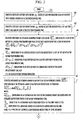
Figure 1 , asystem 10 for estimating a state vector associated with abattery 12 is illustrated. Thebattery 12 includes at least abattery cell 14. Of course, thebattery 12 can include a plurality of additional battery cells. Each battery cell can be either a rechargeable battery cell or a non-rechargeable battery cell. Further, each battery cell can be constructed using an anode and a cathode having electro-chemical configurations known to those skilled in the art. An input variable is defined as a value of a battery input signal at a specific time. For example, an input variable can comprise one of a current entering the battery and a temperature of the battery. An output variable is defined as a value of a battery output signal at a specific time. For example, an output variable can comprise one of a battery output voltage and a battery pressure. - The
system 10 includes one ormore voltage sensors 20, aload circuit 26, and a computational unit such as acomputer 28, and may also include one or more of atemperature sensor 22, and acurrent sensor 24. - The
voltage sensor 20 is provided to generate a first output signal indicative of the voltage produced by one or more of the battery cells of thebattery 12. Thevoltage sensor 20 is electrically coupled between the I/O interface 46 of thecomputer 28 and thebattery 12. Thevoltage sensor 20 transfers the first output signal to thecomputer 28. For clarity of presentation, a single voltage sensor will be described herein. However, it should be noted that in an alternate embodiment of system 10 a plurality of voltage sensors (e.g., one voltage sensor per battery cell) are utilized insystem 10. - The
temperature sensor 22 is provided to generate a second output signal indicative of one or more temperatures of thebattery 12. Thetemperature sensor 22 is disposed proximate thebattery 12 and is electrically coupled to the I/O interface 46 of thecomputer 28. Thetemperature sensor 22 transfers the second output signal to thecomputer 28. For clarity of presentation, a single temperature sensor will be described herein. However, it should be noted that in an alternate embodiment of system 10 a plurality of temperature sensors (e.g., one temperature sensor per battery cell) are utilized insystem 10. - The
current sensor 24 is provided to generate a third output signal indicative of a current sourced or sunk by the battery cells of thebattery 12. Thecurrent sensor 24 is electrically coupled between thebattery 12 and theload circuit 26. Thecurrent sensor 24 is further electrically coupled to the I/O interface 46 of thecomputer 28. Thecurrent sensor 24 transfers the third output signal to thecomputer 28. - The
load circuit 26 is electrically coupled to thecurrent sensor 24 and sinks or sources a current from thebattery 12. Theload circuit 26 comprises any electrical device that can be electrically coupled to thebattery 12. - The
computer 28 is provided for determining an estimated battery state vector associated with thebattery 12, as will be explained in greater detail below. Thecomputer 28 includes a central processing unit (CPU) 40, a read-only memory (ROM) 44, a volatile memory such as a random access memory (RAM) 45 and an input/output (I/O)interface 46. TheCPU 40 operably communicates with the ROM 44, theRAM 45, and the I/O interface 46. TheCPU 40 includes aclock 42. The computer readable media including ROM 44 andRAM 46 may be implemented using any of a number of known memory devices such as PROMs, EPROMs, EEPROMS, flash memory or any other electric, magnetic, optical or combination memory device capable of storing data, some of which represent executable instructions used by theCPU 40. - For purposes of understanding, the notation utilized in the equations of the following methods will be described. The circumflex symbol indicates an estimated or predicted quantity (e.g., x̂ indicates an estimate of the true quantity x). The superscript symbol "-" indicates an a priori estimate (i.e., a prediction of a quantity's present value based on past data). The superscript symbol "+" indicates an a posteriori estimate (e.g.,


- Before providing a detailed discussion of the methodologies for determining a state associated with the
battery 12, a general overview will be provided. The state vector may include, for example, a state of charge (SOC) value associated with thebattery 12, a hysteresis voltage, or a polarization voltage. The SOC value is a value from 0-100 percent, that indicates a present available capacity of thebattery 12 that may be used to do work. - A mathematical model of battery cell behavior is used in the method to compute an estimate of the state vector of the
battery 12. It is assumed that a mathematical model of the battery cell dynamics is known, and may be expressed using a discrete-time state-space model comprising a state equation and an output equation, as will be described below. - The state equation utilized to determine the state vector associated with the
battery 12 is as follows:
wherein, - xk is the state vector associated with the
battery 12 at time index k; - uk is a variable representing a known/deterministic input to the
battery 12; - wk is a battery input noise vector that models some unmeasured input which affects the state of the system; and
- f(x k-1 ,u k-1 ,w k-1 ,k-1) is a state transition function.
- An output vector associated with the
battery 12 is determined utilizing the following equation:
wherein, - h(xk,uk,vk,k) is a measurement function; and
- vk is sensor noise that affects the measurement of the output of
battery 12 in a memory-less mode, but does not affect the state vector ofbattery 12. - Referring to
Figures 2-5 , a method for determining an estimated battery state vector indicative of a state of thebattery 12 in accordance with an exemplary embodiment will now be explained. The method can be implemented utilizing software algorithms executed by thecontroller 28. The software algorithms are stored in either the ROM 44 or theRAM 45. - At
step 60, thecomputer 28 generates a battery input vector uk having at least one measured value of a battery input variable obtained at a first predetermined time. - Next at
step 62, thecomputer 28 generates a battery output vector yk having at least one measured value of a battery output variable obtained at the first predetermined time. - Next at
step 64, thecomputer 28 determines an estimated augmented battery state vector

-

- E[w k-1] corresponds to an expected value of a battery input noise vector at the second predetermined time;
- E[v k-1] corresponds to an expected value of a sensor noise vector at the second predetermined time; and
- T is the matrix/vector transpose operation.
- Next at
step 66, thecomputer 28 determines an estimated augmented battery state vector covariance matrix

where, -

- ∑ w corresponds to a covariance matrix associated with a battery input noise vector;
- ∑ v corresponds to a covariance matrix associated with a sensor noise vector; and diag( ) is a function that composes a block-diagonal matrix from its input arguments.
- Next at
step 68, thecomputer 28 determines a plurality of estimated augmented battery state vectors

where, -


- γ corresponds to a constant value.
- Next at
step 70, thecomputer 28 determines a plurality of predicted battery state vectors

where -


- u k-1 corresponds to a battery input vector at the second predetermined time;
-


-


- k-1 corresponds to the second predetermined time.
- Next at
step 72, acomputer 28 determines a plurality of predicted battery output vectors Yk , each indicative of outputs of the battery at the first predetermined time, utilizing the following equation:
where, - Yk,i corresponds to the ith member of the plurality Yk ;
-


- k corresponds to the first predetermined time.
- Next at
step 74, thecomputer 28 determines a predicted battery state vector


where, -

- p corresponds to the number of members in the plurality

- Next at
step 76, thecomputer 28 determines a predicted battery state vector covariance matrix

where,
- Next at
step 78, thecomputer 28 determines a predicted battery output vector ŷk indicative of outputs of the battery at the first predetermined time, utilizing the following equation:
- Next at
step 80, thecomputer 28 determines a predicted battery output vector covariance matrix

- Next at
step 82, thecomputer 28 determines a predicted cross-covariance matrix

- Next at
step 84, thecomputer 28 determines a gain matrix Lk , utilizing the following equation:
- Next at
step 86, thecomputer 28 determines an estimated battery state vector

- Next at
step 88, thecomputer 28 determines an estimated battery state vector covariance matrix

- Next at
step 90, thecomputer 28 selects new first and second predetermined times. Afterstep 90, the method returns to step 60. - Referring to
Figures 6-9 , a method for determining an estimated battery state vector indicative of a state of thebattery 12 in accordance with another exemplary embodiment will now be explained. The method can be implemented utilizing software algorithms executed by thecontroller 28. The software algorithms are stored in either the ROM 44 or theRAM 45. - At
step 100, thecomputer 28 generates a battery input vector uk having at least one measured value of a battery input variable obtained at a first predetermined time. - Next at
step 102, thecomputer 28 generates a battery output vector yk having at least one measured value of a battery output variable obtained at the first predetermined time. - Next at
step 104,computer 28 determines an estimated augmented battery state vector
battery 12 at a second predetermined time prior to the first predetermined time using the equation:
where, -

- E[w k-1] corresponds to an expected value of a battery input noise vector at the second predetermined time;
- E[v k-1] corresponds to an expected value of a sensor noise vector at the second predetermined time; and
- T is the matrix/vector transpose operation.
- Next at
step 106, thecomputer 28 determines an estimated augmented battery state vector square-root covariance matrix

where, -

- Sw corresponds to a square-root covariance matrix associated with a battery input noise vector;
- Sv corresponds to a square-root covariance matrix associated with a sensor noise vector; and
- diag( ) is a function that composes a block-diagonal matrix from its input arguments.
- Next at
step 108, thecomputer 28 determines a plurality of estimated augmented battery state vectors

where, γ corresponds to a constant value. - Next at
step 110, thecomputer 28 determines a plurality of predicted battery state vectors

where -


- u k-1 corresponds to a battery input vector at the second predetermined time;


- k-1 corresponds to the second time.
- Next at
step 112, thecomputer 28 determines a plurality of predicted battery output vectors
battery 12 at the first predetermined time, utilizing the following equation:
where, -


-


- k corresponds to the first predetermined time.
- Next at
step 114, thecomputer 28 determines a predicted battery state vector


where, -

- p corresponds to the number of members in the plurality

- Next at
step 116, thecomputer 28 determines a predicted battery state vector square-root covariance matrix

where, -

- qr{} is a function that computes a Q-R matrix decomposition of its input argument and returns the upper-triangular portion of the R matrix.
- Next at
step 118,computer 28 determines a predicted battery output vector ŷk indicative of outputs of the battery at the first predetermined time, utilizing the following equation:
- Next at
step 120, thecomputer 28 determines a predicted battery output vector square-root covariance matrix Sỹ ,k , utilizing the following equation:
- Next at
step 122, thecomputer 28 determines a predicted cross-covariance matrix

- Next at
step 124, thecomputer 28 determines a gain matrix Lk, utilizing the following equation:
- Next at
step 126, thecomputer 28 determines an estimated battery state vector

- Next at
step 128, thecomputer 28 determines an estimated battery state vector square-root covariance matrix

where downdate{ } computes the matrix downdate operation on its first argument using its second argument. - Next at
step 130, thecomputer 28 selects new first and second predetermined times. Afterstep 130, the method advances to step 100. - The system, method, and article of manufacture for determining an estimated battery state vector indicative of the state of a battery provide a substantial advantage over other systems and methods. In particular, the system, method, and article of manufacture provide a technical effect of more accurately determining the estimated battery state vector for a battery having non-linear operational characteristics.
- The above-described methods can be embodied in the form of computer program code containing instructions embodied in tangible media, such as floppy diskettes, CD ROMs, hard drives, or any other computer-readable storage medium, wherein, when the computer program code is loaded into and executed by a computer, the computer becomes an apparatus for practicing the invention. The above-described methods can also be embodied in the form of computer program code, for example, whether stored in a storage medium, loaded into and/or executed by a computer, or transmitted over some transmission medium, loaded into and/or executed by a computer, or transmitted over some transmission medium, such as over electrical wiring or cabling, through fiber optics, or via electromagnetic radiation, wherein, when the computer program code is loaded into an executed by a computer, the computer becomes an apparatus for practicing the methods. When implemented on a general-purpose microprocessor, the computer program code segments configure the microprocessor to create specific logic circuits.
- While the invention is described with reference to the exemplary embodiments, it will be understood by those skilled in the art that various changes may be made and equivalent elements e may be substituted for elements thereof without departing from the scope of the invention. In addition, many modifications may be made to the teachings of the invention to adapt to a particular situation without departing from the scope thereof. Therefore, is intended that the invention not be limited the embodiment disclosed for carrying out this invention, but that the invention includes all embodiments falling with the scope of the intended claims. Moreover, the use of the term's first, second, etc. does not denote any order of importance, but rather the term's first, second, etc. are used to distinguish one element from another.
Claims (20)
- A method for determining an estimated battery state vector indicative of a state of a battery at a first predetermined time, characterised in that the method comprising:determining a first plurality of estimated augmented battery state vectors that are indicative of a state of the battery, a battery input noise, a sensor noise, an uncertainty of the state of the battery, an uncertainty of the battery input noise, and an uncertainty of the sensor noise at a second predetermined time prior to the first predetermined time;determining a second plurality of predicted battery state vectors that are indicative of the state of the battery and an uncertainty of the state of the battery at the first predetermined time based on the first plurality of estimated augmented battery state vectors;determining a third plurality of predicted battery output vectors that are indicative of at least one output variable of the battery and an uncertainty of the output variable at the first predetermined time based on the first plurality of estimated augmented battery state vectors and the second plurality of predicted battery state vectors;determining a first battery output vector having at least one measured value of a battery output variable; anddetermining a first estimated battery state vector indicative of the state of the battery at the first predetermined time based on the second plurality of predicted battery state vectors, the third plurality of predicted battery output vectors, and the first battery output vector.
- The method of claim 1, wherein determining the first plurality of estimated augmented battery state vectors comprises:retrieving an estimated battery state vector indicative of the state of the battery at the second predetermined time from a memory;determining a first estimated augmented battery state vector indicative of the state of the battery, the battery input noise, and the sensor noise at the second predetermined time, based on the estimated battery state vector, an expected battery input noise vector, and an expected sensor noise vector;retrieving an estimated battery state vector covariance matrix indicative of an uncertainty of the state of the battery at the second predetermined time from the memory;determining a first estimated augmented battery state vector covariance matrix indicative based on the estimated battery state vector covariance matrix, a covariance matrix indicative of an uncertainty of the battery input noise and a covariance matrix indicative of an uncertainty of the sensor noise; anddetermining the first plurality of estimated augmented battery state vectors based on the first estimated augmented battery state vector and the first estimated augmented battery state vector covariance matrix.
- The method of claim 2, wherein determining the first plurality of estimated augmented battery state vectors comprises:setting one member of the first plurality of estimated augmented battery state vectors equal to the first estimated augmented battery state vector;setting a first additional set of L members of the first plurality of estimated augmented battery state vectors equal to the first estimated augmented battery state vector added to a constant value multiplied by respective columns extracted from a matrix square-root of the first estimated augmented battery state vector covariance matrix, where L is the length of the first estimated augmented battery state vector; andsetting a second additional set of L members of the first plurality of estimated augmented battery state vectors equal to the constant value multiplied by respective columns extracted from the matrix square-root of the first estimated augmented battery state vector covariance matrix subtracted from the first estimated augmented battery state vector.
- The method of claim 1, wherein determining the first plurality of estimated augmented battery state vectors comprises:retrieving an estimated battery state vector indicative of the state of the battery at the second predetermined time from a memory;determining a first estimated augmented battery state vector indicative of the state of the battery, the battery input noise, and the sensor noise at the second predetermined time based on the estimated battery state vector, an expected battery input noise vector, and an expected sensor noise vector;retrieving an estimated battery state vector square-root covariance matrix indicative of an uncertainty of the state of the battery at the second predetermined time from the memory;determining a first estimated augmented battery state vector square-root covariance matrix indicative of an uncertainty of the state of the battery, the battery input noise, and the sensor noise, based on the estimated battery state vector square-root covariance matrix, a covariance matrix indicative of an uncertainty of the battery input noise and a covariance matrix indicative of an uncertainty of the sensor noise; anddetermining the first plurality of estimated augmented battery state vectors based on the first estimated augmented battery state vector and the first estimated augmented battery state vector square-root covariance matrix.
- The method of claim 4, wherein determining the first plurality of estimated augmented battery state vectors comprises:setting one member of the first plurality of estimated augmented battery state vectors equal to the first estimated augmented battery state vector;setting a first additional set of L members of the first plurality of estimated augmented battery state vectors equal to the first estimated augmented battery state vector added to a constant value multiplied by respective columns extracted from the estimated augmented battery state vector square-root covariance matrix, where L is the length of the estimated augmented battery state vector; andsetting a second additional set of L members of the first plurality of estimated augmented battery state vectors equal to the constant value multiplied by respective columns extracted from the first estimated augmented battery state vector square-root covariance matrix subtracted from the first estimated augmented battery state vector.
- The method of claim 1, wherein determining the second plurality of predicted battery state vectors comprises:extracting values indicative of the state of the battery and of an uncertainty of the state of the battery at the second predetermined time from the first plurality of estimated augmented battery state vectors, to obtain a fourth plurality of estimated battery state vectors;extracting values indicative of the battery input noise and an uncertainty of the battery input noise at the second predetermined time from the first plurality of estimated augmented battery state vectors, to obtain a fifth plurality of estimated battery input noise vectors;generating the first battery input vector having at least one measured value of a battery input variable at the second predetermined time; anddetermining the second plurality of predicted battery state vectors based on the fourth plurality of predicted battery state vectors, the fifth plurality of predicted battery input noise vectors, and the first battery input vector.
- The method of claim 1, wherein determining the third plurality of predicted battery output vectors comprises:extracting values indicative of the sensor noise and of an uncertainty of the sensor noise at the second predetermined time from the first plurality of estimated augmented battery state vectors, to obtain a fourth plurality of estimated sensor noise vectors;generating the first battery input vector having at least one measured value of a battery input variable at the first predetermined time; anddetermining the third plurality of predicted battery output vectors based on the second plurality of predicted battery state vectors, the first battery input vector, the fourth plurality of estimated sensor noise vectors.
- The method of claim 1, wherein determining the first estimated battery state vector comprises:determining a first predicted battery state vector indicative of the state of the battery at the first predetermined time based on the second plurality of predicted battery state vectors;determining a first predicted battery output vector indicative of at least one output variable of the battery at the first predetermined time based on the third plurality of predicted output vectors;determining a gain matrix based on the first predicted battery state vector, the first predicted battery output vector, the second plurality of predicted battery state vectors, and the third plurality of predicted battery output vectors; andcalculating the first estimated battery state vector based on the first predicted battery state vector, the first predicted battery output vector, the gain matrix, and the first battery output vector.
- The method of claim 8, wherein determining the first predicted battery state vector comprises calculating a weighted average of the second plurality of predicted battery state vectors.
- The method of claim 8, wherein determining the first predicted battery output vector comprises calculating a weighted average of the third plurality of predicted battery output vectors.
- The method of claim 8, wherein determining the gain matrix comprises:determining a first predicted battery output vector covariance matrix based on the first predicted battery output vector and the third plurality of predicted battery output vectors;determining a first predicted cross-covariance matrix between a battery output vector and a battery state vector based on the first predicted battery output vector, the third plurality of predicted battery output vectors, the first predicted battery state vector, and the second plurality of predicted battery state vectors; andcalculating the gain matrix based on the first predicted cross-covariance matrix and the first predicted battery output vector covariance matrix.
- The method of claim 11, wherein determining the first predicted battery output vector covariance matrix comprises:determining a first predicted battery output vector square-root covariance matrix based on the first predicted battery output vector and the third plurality of predicted battery output vectors; andcalculating the first predicted battery output vector covariance matrix based on the first predicted battery output vector square-root covariance matrix and the first predicted battery output vector square-root covariance matrix.
- The method of claim 8, wherein calculating the first estimated battery state vector comprises:determining an innovation vector based on the first battery output vector and the first predicted battery output vector;determining an update vector based on the gain matrix and the innovation vector; andcalculating the first estimated battery state vector based on the predicted battery state vector and the update vector.
- The method of claim 8, further comprising determining an estimated battery state vector covariance matrix at the first predetermined time based on the first predicted battery state vector, the second plurality of predicted battery state vectors, the gain matrix, and the first predicted battery output vector covariance matrix.
- The method of claim 8, further comprising determining an estimated battery state vector square-root covariance matrix at the first predetermined time based on the first predicted battery state vector, the second plurality of predicted battery state vectors, the gain matrix, and a predicted battery output vector square-root covariance matrix.
- A system for determining an estimated battery state vector indicative of a state of a battery at a first predetermined time, characterised in that the system comprising:a sensor configured to generate a first signal indicative of an output variable of the battery; anda computer operably coupled to the sensor, the computer configured to determine a first plurality of estimated augmented battery state vectors that are indicative of a state of the battery, a battery input noise, a sensor noise, an uncertainty of the state of the battery, an uncertainty of the battery input noise, and an uncertainty of the sensor noise at a second predetermined time prior to the first predetermined time, the computer further configured to determine a second plurality of predicted battery state vectors that are indicative of the state of the battery and an uncertainty of the state of the battery at the first predetermined time based on the first plurality of estimated augmented battery state vectors, the computer further configured to determine a third plurality of predicted battery output vectors that are indicative of an at least one output variable of the battery and an uncertainty of the output variable at the first predetermined time based on the first plurality of estimated augmented battery state vectors and the second plurality of predicted battery state vectors, the computer further configured to determine a first battery output vector based on the first signal, the computer further configured to determine a first estimated battery state vector indicative of the state of the battery at the first predetermined time based on the second plurality of predicted battery state vectors, the third plurality of predicted battery output vectors, and the first battery output vector.
- The system of claim 16, wherein the computer is further configured to retrieve an estimated battery state vector indicative of the state of the battery at the second predetermined time from a memory, the computer further configured to determine a first estimated augmented battery state vector indicative of the state of the battery, the battery input noise and the sensor noise at the second predetermined time, based on the estimated battery state vector, an expected battery input noise vector, and an expected sensor noise vector, the computer further configured to retrieve an estimated battery state vector covariance matrix indicative of an uncertainty of the state of the battery at the second predetermined time from the memory, the computer further configured to determine a first estimated augmented battery state vector covariance matrix indicative of an uncertainty of the state of the battery, the battery input noise, and the sensor noise, based on the estimated battery state vector covariance matrix, a covariance matrix indicative of an uncertainty of the battery input noise and a covariance matrix indicative of an uncertainty of the sensor noise, the computer further configured to determine the first plurality of estimated augmented battery state vectors based on the first estimated augmented battery state vector and the first estimated augmented battery state vector covariance matrix.
- The system of claim 16, wherein the computer is further configured to determine a first predicted battery state vector indicative of the state of the battery at the first predetermined time based on the second plurality of predicted battery state vectors, the computer further configured to determine a first predicted battery output vector indicative of at least one output variable of the battery at the first predetermined time based on the third plurality of predicted output vectors, the computer further configured to determine a gain matrix based on the first predicted battery state vector, the first predicted battery output vector, the second plurality of predicted battery state vectors, and the third plurality of predicted battery output vectors, the computer further configured to calculate the first estimated battery state vector based on the first predicted battery state vector, the first predicted battery output vector, the gain matrix, and the first battery output vector.
- An article of manufacture, characterised by comprising:a computer storage medium having a computer program encoded therein for determining an estimated battery state vector indicative of a state of a battery at a first predetermined time, the computer storage medium comprising:code for determining a first plurality of estimated augmented battery state vectors that are indicative of a state of the battery, a battery input noise, a sensor noise, an uncertainty of the state of the battery, an uncertainty of the battery input noise, and an uncertainty of the sensor noise at a second predetermined time prior to the first predetermined time;code for determining a second plurality of predicted battery state vectors that are indicative of the state of the battery and an uncertainty of the state of the battery at the first predetermined time based on the first plurality of estimated augmented battery state vectors;code for determining a third plurality of predicted battery output vectors that are indicative of at least one output variable of the battery and of an uncertainty of the output variable at the first predetermined time based on the first plurality of estimated augmented battery state vectors and the second plurality of predicted battery state vectors;code for determining a first battery output vector having at least one measured value of a battery output variable; andcode for determining a first estimated battery state vector indicative of the state of the battery at the first predetermined time based on the second plurality of predicted battery state vectors, the third plurality of predicted battery output vectors, and the first battery output vector.
- The article of manufacture of claim 19, wherein the code for determining the first estimated battery state vector comprises:code for determining a first predicted battery state vector indicative of the state of the battery at the first predetermined time based on the second plurality of predicted battery state vectors;code for determining a first predicted battery output vector indicative of at least one output variable of the battery at the first predetermined time based on the third plurality of predicted output vectors;code for determining a gain matrix based on the first predicted battery state vector, the first predicted battery output vector, the second plurality of predicted battery state vectors, and the third plurality of predicted battery output vectors; andcode for calculating the first estimated battery state vector based on the first predicted battery state vector, the first predicted battery output vector, the gain matrix, and the first battery output vector.
Applications Claiming Priority (2)
| Application Number | Priority Date | Filing Date | Title |
|---|---|---|---|
| US11/272,371 US7446504B2 (en) | 2005-11-10 | 2005-11-10 | System, method, and article of manufacture for determining an estimated battery state vector |
| PCT/KR2006/004682 WO2007055520A1 (en) | 2005-11-10 | 2006-11-09 | System, method, and article of manufacture for determining an estimated battery state vector |
Publications (3)
| Publication Number | Publication Date |
|---|---|
| EP1949523A1 EP1949523A1 (en) | 2008-07-30 |
| EP1949523A4 EP1949523A4 (en) | 2013-10-09 |
| EP1949523B1 true EP1949523B1 (en) | 2014-08-13 |
Family
ID=38003085
Family Applications (1)
| Application Number | Title | Priority Date | Filing Date |
|---|---|---|---|
| EP06843823.3A Active EP1949523B1 (en) | 2005-11-10 | 2006-11-09 | System, method, and article of manufacture for determining an estimated battery state vector |
Country Status (6)
| Country | Link |
|---|---|
| US (3) | US7446504B2 (en) |
| EP (1) | EP1949523B1 (en) |
| JP (1) | JP4920693B2 (en) |
| KR (1) | KR101355960B1 (en) |
| CN (1) | CN101305509B (en) |
| WO (1) | WO2007055520A1 (en) |
Families Citing this family (47)
| Publication number | Priority date | Publication date | Assignee | Title |
|---|---|---|---|---|
| US7321220B2 (en) * | 2003-11-20 | 2008-01-22 | Lg Chem, Ltd. | Method for calculating power capability of battery packs using advanced cell model predictive techniques |
| KR100759706B1 (en) * | 2005-05-11 | 2007-09-17 | 주식회사 엘지화학 | Method of estimating soc of battery for hybrid electric vehicle |
| US7723957B2 (en) * | 2005-11-30 | 2010-05-25 | Lg Chem, Ltd. | System, method, and article of manufacture for determining an estimated battery parameter vector |
| US7400115B2 (en) * | 2006-02-09 | 2008-07-15 | Lg Chem, Ltd. | System, method, and article of manufacture for determining an estimated combined battery state-parameter vector |
| US8628872B2 (en) * | 2008-01-18 | 2014-01-14 | Lg Chem, Ltd. | Battery cell assembly and method for assembling the battery cell assembly |
| US7994755B2 (en) | 2008-01-30 | 2011-08-09 | Lg Chem, Ltd. | System, method, and article of manufacture for determining an estimated battery cell module state |
| US7957921B2 (en) * | 2008-02-19 | 2011-06-07 | GM Global Technology Operations LLC | Model-based estimation of battery hysteresis |
| US7883793B2 (en) * | 2008-06-30 | 2011-02-08 | Lg Chem, Ltd. | Battery module having battery cell assemblies with alignment-coupling features |
| US9759495B2 (en) | 2008-06-30 | 2017-09-12 | Lg Chem, Ltd. | Battery cell assembly having heat exchanger with serpentine flow path |
| US9140501B2 (en) * | 2008-06-30 | 2015-09-22 | Lg Chem, Ltd. | Battery module having a rubber cooling manifold |
| US8426050B2 (en) * | 2008-06-30 | 2013-04-23 | Lg Chem, Ltd. | Battery module having cooling manifold and method for cooling battery module |
| US8067111B2 (en) * | 2008-06-30 | 2011-11-29 | Lg Chem, Ltd. | Battery module having battery cell assembly with heat exchanger |
| US8202645B2 (en) | 2008-10-06 | 2012-06-19 | Lg Chem, Ltd. | Battery cell assembly and method for assembling the battery cell assembly |
| US9337456B2 (en) * | 2009-04-20 | 2016-05-10 | Lg Chem, Ltd. | Frame member, frame assembly and battery cell assembly made therefrom and methods of making the same |
| US8663828B2 (en) | 2009-04-30 | 2014-03-04 | Lg Chem, Ltd. | Battery systems, battery module, and method for cooling the battery module |
| US8663829B2 (en) | 2009-04-30 | 2014-03-04 | Lg Chem, Ltd. | Battery systems, battery modules, and method for cooling a battery module |
| US8852778B2 (en) | 2009-04-30 | 2014-10-07 | Lg Chem, Ltd. | Battery systems, battery modules, and method for cooling a battery module |
| US8403030B2 (en) | 2009-04-30 | 2013-03-26 | Lg Chem, Ltd. | Cooling manifold |
| US8703318B2 (en) * | 2009-07-29 | 2014-04-22 | Lg Chem, Ltd. | Battery module and method for cooling the battery module |
| US8399118B2 (en) | 2009-07-29 | 2013-03-19 | Lg Chem, Ltd. | Battery module and method for cooling the battery module |
| US8399119B2 (en) | 2009-08-28 | 2013-03-19 | Lg Chem, Ltd. | Battery module and method for cooling the battery module |
| US8918299B2 (en) * | 2009-12-02 | 2014-12-23 | American Electric Vehicles, Inc. | System and method for maximizing a battery pack total energy metric |
| US8041522B2 (en) * | 2009-12-02 | 2011-10-18 | American Electric Vehicles, Ind. | System and method for recursively estimating battery cell total capacity |
| US8427105B2 (en) * | 2009-12-02 | 2013-04-23 | Gregory L. Plett | System and method for equalizing a battery pack during a battery pack charging process |
| US8341449B2 (en) | 2010-04-16 | 2012-12-25 | Lg Chem, Ltd. | Battery management system and method for transferring data within the battery management system |
| US9147916B2 (en) | 2010-04-17 | 2015-09-29 | Lg Chem, Ltd. | Battery cell assemblies |
| US8758922B2 (en) | 2010-08-23 | 2014-06-24 | Lg Chem, Ltd. | Battery system and manifold assembly with two manifold members removably coupled together |
| US8353315B2 (en) | 2010-08-23 | 2013-01-15 | Lg Chem, Ltd. | End cap |
| US8920956B2 (en) | 2010-08-23 | 2014-12-30 | Lg Chem, Ltd. | Battery system and manifold assembly having a manifold member and a connecting fitting |
| US8469404B2 (en) | 2010-08-23 | 2013-06-25 | Lg Chem, Ltd. | Connecting assembly |
| US9005799B2 (en) | 2010-08-25 | 2015-04-14 | Lg Chem, Ltd. | Battery module and methods for bonding cell terminals of battery cells together |
| US8662153B2 (en) | 2010-10-04 | 2014-03-04 | Lg Chem, Ltd. | Battery cell assembly, heat exchanger, and method for manufacturing the heat exchanger |
| US8288031B1 (en) | 2011-03-28 | 2012-10-16 | Lg Chem, Ltd. | Battery disconnect unit and method of assembling the battery disconnect unit |
| US8449998B2 (en) | 2011-04-25 | 2013-05-28 | Lg Chem, Ltd. | Battery system and method for increasing an operational life of a battery cell |
| US9178192B2 (en) | 2011-05-13 | 2015-11-03 | Lg Chem, Ltd. | Battery module and method for manufacturing the battery module |
| US8993136B2 (en) | 2011-06-30 | 2015-03-31 | Lg Chem, Ltd. | Heating system for a battery module and method of heating the battery module |
| US8974929B2 (en) | 2011-06-30 | 2015-03-10 | Lg Chem, Ltd. | Heating system for a battery module and method of heating the battery module |
| US8859119B2 (en) | 2011-06-30 | 2014-10-14 | Lg Chem, Ltd. | Heating system for a battery module and method of heating the battery module |
| US8974928B2 (en) | 2011-06-30 | 2015-03-10 | Lg Chem, Ltd. | Heating system for a battery module and method of heating the battery module |
| US9496544B2 (en) | 2011-07-28 | 2016-11-15 | Lg Chem. Ltd. | Battery modules having interconnect members with vibration dampening portions |
| US8922217B2 (en) * | 2012-05-08 | 2014-12-30 | GM Global Technology Operations LLC | Battery state-of-charge observer |
| US8890484B2 (en) * | 2012-05-08 | 2014-11-18 | GM Global Technology Operations LLC | Battery state-of-charge estimator using robust H∞ observer |
| US8751086B2 (en) | 2012-08-21 | 2014-06-10 | Ford Global Technologies, Llc | Online battery capacity estimation |
| KR101798201B1 (en) | 2014-10-01 | 2017-11-15 | 주식회사 엘지화학 | Method and Apparatus for estimating discharge power of secondary battery |
| ES2945600T3 (en) * | 2015-01-14 | 2023-07-04 | Corvus Energy Ltd | Method and system to iteratively determine state of charge of a battery cell |
| KR101846642B1 (en) | 2015-02-02 | 2018-04-06 | 주식회사 엘지화학 | Method for determining resistance factor of secondary battery, and Apparatus and Method for estimating charging power of secondary battery using determined resistance factor |
| CN106855612B (en) * | 2017-02-21 | 2019-09-24 | 山东大学 | The fractional order KiBaM battery model and parameter identification method of meter and non-linear capacity characteristic |
Family Cites Families (26)
| Publication number | Priority date | Publication date | Assignee | Title |
|---|---|---|---|---|
| US4390841A (en) * | 1980-10-14 | 1983-06-28 | Purdue Research Foundation | Monitoring apparatus and method for battery power supply |
| TW269727B (en) * | 1995-04-03 | 1996-02-01 | Electrosource Inc | Battery management system |
| US6285163B1 (en) * | 1998-05-28 | 2001-09-04 | Toyota Jidosha Kabushiki Kaisha | Means for estimating charged state of battery and method for estimating degraded state of battery |
| JPH11346444A (en) * | 1998-06-02 | 1999-12-14 | Toyota Motor Corp | Estimating method of battery charged condition |
| US6353815B1 (en) * | 1998-11-04 | 2002-03-05 | The United States Of America As Represented By The United States Department Of Energy | Statistically qualified neuro-analytic failure detection method and system |
| DE10021161A1 (en) * | 2000-04-29 | 2001-10-31 | Vb Autobatterie Gmbh | Method for determining the state of charge and the load capacity of an electric accumulator |
| DE10056969A1 (en) * | 2000-11-17 | 2002-05-23 | Bosch Gmbh Robert | Determining battery charge involves computing charge in first range of operation on basis of model computation in which measured and computed battery voltages are equalized by feedback |
| JP3936179B2 (en) | 2001-11-30 | 2007-06-27 | パナソニック・イーブイ・エナジー株式会社 | Battery power supply device and current detection method thereof |
| DE10106508A1 (en) * | 2001-02-13 | 2002-08-29 | Bosch Gmbh Robert | Method and arrangement for determining the performance of a battery |
| US6441586B1 (en) * | 2001-03-23 | 2002-08-27 | General Motors Corporation | State of charge prediction method and apparatus for a battery |
| US6727708B1 (en) * | 2001-12-06 | 2004-04-27 | Johnson Controls Technology Company | Battery monitoring system |
| JP4097183B2 (en) * | 2001-12-27 | 2008-06-11 | パナソニックEvエナジー株式会社 | Secondary battery remaining capacity estimation method and apparatus, and battery pack system |
| US6534954B1 (en) * | 2002-01-10 | 2003-03-18 | Compact Power Inc. | Method and apparatus for a battery state of charge estimator |
| JP4228760B2 (en) * | 2002-07-12 | 2009-02-25 | トヨタ自動車株式会社 | Battery charge state estimation device |
| JP3539424B2 (en) * | 2002-07-24 | 2004-07-07 | 日産自動車株式会社 | Electric vehicle control device |
| CN1246704C (en) * | 2002-10-07 | 2006-03-22 | 陈清泉 | Method for estimating residual capacity of storage battery for electric vehicle |
| EP1590679B1 (en) * | 2003-01-30 | 2008-08-20 | Robert Bosch GmbH | State variable and parameter estimator comprising several partial models for an electrical energy storage device |
| DE10335930B4 (en) * | 2003-08-06 | 2007-08-16 | Vb Autobatterie Gmbh & Co. Kgaa | Method for determining the state of an electrochemical storage battery |
| US6927554B2 (en) * | 2003-08-28 | 2005-08-09 | General Motors Corporation | Simple optimal estimator for PbA state of charge |
| US7109685B2 (en) * | 2003-09-17 | 2006-09-19 | General Motors Corporation | Method for estimating states and parameters of an electrochemical cell |
| US20050100786A1 (en) | 2003-09-19 | 2005-05-12 | Ryu Duk H. | Nonaqueous lithium secondary battery with cyclability and/or high temperature safety improved |
| US20050127874A1 (en) | 2003-12-12 | 2005-06-16 | Myoungho Lim | Method and apparatus for multiple battery cell management |
| DE102004005478B4 (en) * | 2004-02-04 | 2010-01-21 | Vb Autobatterie Gmbh | Method for determining parameters for electrical states of a storage battery and monitoring device for this purpose |
| US7315789B2 (en) * | 2004-11-23 | 2008-01-01 | Lg Chem, Ltd. | Method and system for battery parameter estimation |
| US7612532B2 (en) * | 2005-06-21 | 2009-11-03 | Gm Global Technology Operations, Inc. | Method for controlling and monitoring using a state estimator having variable forgetting factors |
| US7400115B2 (en) * | 2006-02-09 | 2008-07-15 | Lg Chem, Ltd. | System, method, and article of manufacture for determining an estimated combined battery state-parameter vector |
-
2005
- 2005-11-10 US US11/272,371 patent/US7446504B2/en active Active
-
2006
- 2006-11-09 WO PCT/KR2006/004682 patent/WO2007055520A1/en active Application Filing
- 2006-11-09 EP EP06843823.3A patent/EP1949523B1/en active Active
- 2006-11-09 JP JP2008539935A patent/JP4920693B2/en active Active
- 2006-11-09 CN CN2006800419199A patent/CN101305509B/en active Active
- 2006-11-09 KR KR1020087013682A patent/KR101355960B1/en active IP Right Grant
-
2008
- 2008-10-01 US US12/243,600 patent/US7884613B2/en active Active
- 2008-10-01 US US12/243,616 patent/US7656123B2/en active Active
Also Published As
| Publication number | Publication date |
|---|---|
| JP2009516165A (en) | 2009-04-16 |
| CN101305509B (en) | 2010-12-29 |
| US7884613B2 (en) | 2011-02-08 |
| US7656123B2 (en) | 2010-02-02 |
| CN101305509A (en) | 2008-11-12 |
| KR101355960B1 (en) | 2014-01-29 |
| US20070103120A1 (en) | 2007-05-10 |
| EP1949523A1 (en) | 2008-07-30 |
| JP4920693B2 (en) | 2012-04-18 |
| WO2007055520A1 (en) | 2007-05-18 |
| EP1949523A4 (en) | 2013-10-09 |
| US20090037125A1 (en) | 2009-02-05 |
| US20090030627A1 (en) | 2009-01-29 |
| US7446504B2 (en) | 2008-11-04 |
| KR20080066994A (en) | 2008-07-17 |
Similar Documents
| Publication | Publication Date | Title |
|---|---|---|
| EP1949523B1 (en) | System, method, and article of manufacture for determining an estimated battery state vector | |
| EP1971872B1 (en) | System, method, and article of manufacture for determining an estimated battery parameter vector | |
| EP3264562B1 (en) | Method for determining an estimated combined battery state-parameter vector | |
| US7521895B2 (en) | System and method for determining both an estimated battery state vector and an estimated battery parameter vector | |
| EP1917536B1 (en) | System and method for estimating a state vector associated with a battery | |
| US7994755B2 (en) | System, method, and article of manufacture for determining an estimated battery cell module state |
Legal Events
| Date | Code | Title | Description |
|---|---|---|---|
| PUAI | Public reference made under article 153(3) epc to a published international application that has entered the european phase |
Free format text: ORIGINAL CODE: 0009012 |
|
| 17P | Request for examination filed |
Effective date: 20080422 |
|
| AK | Designated contracting states |
Kind code of ref document: A1 Designated state(s): DE FR GB IT |
|
| RBV | Designated contracting states (corrected) |
Designated state(s): DE FR GB IT |
|
| DAX | Request for extension of the european patent (deleted) | ||
| A4 | Supplementary search report drawn up and despatched |
Effective date: 20130905 |
|
| RIC1 | Information provided on ipc code assigned before grant |
Ipc: H01M 10/48 20060101ALI20130830BHEP Ipc: G01R 31/36 20060101ALI20130830BHEP Ipc: H02J 7/00 20060101AFI20130830BHEP |
|
| GRAP | Despatch of communication of intention to grant a patent |
Free format text: ORIGINAL CODE: EPIDOSNIGR1 |
|
| RIC1 | Information provided on ipc code assigned before grant |
Ipc: H01M 10/48 20060101ALI20140319BHEP Ipc: H02J 7/00 20060101AFI20140319BHEP Ipc: G01R 31/36 20060101ALI20140319BHEP |
|
| INTG | Intention to grant announced |
Effective date: 20140404 |
|
| GRAS | Grant fee paid |
Free format text: ORIGINAL CODE: EPIDOSNIGR3 |
|
| GRAA | (expected) grant |
Free format text: ORIGINAL CODE: 0009210 |
|
| AK | Designated contracting states |
Kind code of ref document: B1 Designated state(s): DE FR GB IT |
|
| REG | Reference to a national code |
Ref country code: GB Ref legal event code: FG4D |
|
| REG | Reference to a national code |
Ref country code: DE Ref legal event code: R096 Ref document number: 602006042724 Country of ref document: DE Effective date: 20140925 |
|
| REG | Reference to a national code |
Ref country code: DE Ref legal event code: R097 Ref document number: 602006042724 Country of ref document: DE |
|
| PLBE | No opposition filed within time limit |
Free format text: ORIGINAL CODE: 0009261 |
|
| STAA | Information on the status of an ep patent application or granted ep patent |
Free format text: STATUS: NO OPPOSITION FILED WITHIN TIME LIMIT |
|
| 26N | No opposition filed |
Effective date: 20150515 |
|
| REG | Reference to a national code |
Ref country code: FR Ref legal event code: PLFP Year of fee payment: 10 |
|
| REG | Reference to a national code |
Ref country code: FR Ref legal event code: PLFP Year of fee payment: 11 |
|
| REG | Reference to a national code |
Ref country code: FR Ref legal event code: PLFP Year of fee payment: 12 |
|
| REG | Reference to a national code |
Ref country code: FR Ref legal event code: PLFP Year of fee payment: 13 |
|
| REG | Reference to a national code |
Ref country code: DE Ref legal event code: R081 Ref document number: 602006042724 Country of ref document: DE Owner name: LG ENERGY SOLUTION LTD., KR Free format text: FORMER OWNER: LG CHEM. LTD., SEOUL, KR Ref country code: DE Ref legal event code: R081 Ref document number: 602006042724 Country of ref document: DE Owner name: LG ENERGY SOLUTION, LTD., KR Free format text: FORMER OWNER: LG CHEM. LTD., SEOUL, KR |
|
| P01 | Opt-out of the competence of the unified patent court (upc) registered |
Effective date: 20230512 |
|
| REG | Reference to a national code |
Ref country code: GB Ref legal event code: 732E Free format text: REGISTERED BETWEEN 20230824 AND 20230831 |
|
| REG | Reference to a national code |
Ref country code: DE Ref legal event code: R081 Ref document number: 602006042724 Country of ref document: DE Owner name: LG ENERGY SOLUTION, LTD., KR Free format text: FORMER OWNER: LG ENERGY SOLUTION LTD., SEOUL, KR |
|
| PGFP | Annual fee paid to national office [announced via postgrant information from national office to epo] |
Ref country code: GB Payment date: 20231023 Year of fee payment: 18 |
|
| PGFP | Annual fee paid to national office [announced via postgrant information from national office to epo] |
Ref country code: IT Payment date: 20231025 Year of fee payment: 18 Ref country code: FR Payment date: 20231024 Year of fee payment: 18 Ref country code: DE Payment date: 20231023 Year of fee payment: 18 |